WO2020080098A1 - Fuel supply device - Google Patents
Fuel supply device Download PDFInfo
- Publication number
- WO2020080098A1 WO2020080098A1 PCT/JP2019/038762 JP2019038762W WO2020080098A1 WO 2020080098 A1 WO2020080098 A1 WO 2020080098A1 JP 2019038762 W JP2019038762 W JP 2019038762W WO 2020080098 A1 WO2020080098 A1 WO 2020080098A1
- Authority
- WO
- WIPO (PCT)
- Prior art keywords
- fuel
- passage
- pressurized
- supply device
- pressurized fuel
- Prior art date
- Legal status (The legal status is an assumption and is not a legal conclusion. Google has not performed a legal analysis and makes no representation as to the accuracy of the status listed.)
- Ceased
Links
Images

Classifications
-
- F—MECHANICAL ENGINEERING; LIGHTING; HEATING; WEAPONS; BLASTING
- F02—COMBUSTION ENGINES; HOT-GAS OR COMBUSTION-PRODUCT ENGINE PLANTS
- F02M—SUPPLYING COMBUSTION ENGINES IN GENERAL WITH COMBUSTIBLE MIXTURES OR CONSTITUENTS THEREOF
- F02M37/00—Apparatus or systems for feeding liquid fuel from storage containers to carburettors or fuel-injection apparatus; Arrangements for purifying liquid fuel specially adapted for, or arranged on, internal-combustion engines
- F02M37/0047—Layout or arrangement of systems for feeding fuel
- F02M37/0052—Details on the fuel return circuit; Arrangement of pressure regulators
-
- F—MECHANICAL ENGINEERING; LIGHTING; HEATING; WEAPONS; BLASTING
- F02—COMBUSTION ENGINES; HOT-GAS OR COMBUSTION-PRODUCT ENGINE PLANTS
- F02M—SUPPLYING COMBUSTION ENGINES IN GENERAL WITH COMBUSTIBLE MIXTURES OR CONSTITUENTS THEREOF
- F02M37/00—Apparatus or systems for feeding liquid fuel from storage containers to carburettors or fuel-injection apparatus; Arrangements for purifying liquid fuel specially adapted for, or arranged on, internal-combustion engines
- F02M37/04—Feeding by means of driven pumps
- F02M37/08—Feeding by means of driven pumps electrically driven
- F02M37/10—Feeding by means of driven pumps electrically driven submerged in fuel, e.g. in reservoir
- F02M37/106—Feeding by means of driven pumps electrically driven submerged in fuel, e.g. in reservoir the pump being installed in a sub-tank
-
- F—MECHANICAL ENGINEERING; LIGHTING; HEATING; WEAPONS; BLASTING
- F02—COMBUSTION ENGINES; HOT-GAS OR COMBUSTION-PRODUCT ENGINE PLANTS
- F02M—SUPPLYING COMBUSTION ENGINES IN GENERAL WITH COMBUSTIBLE MIXTURES OR CONSTITUENTS THEREOF
- F02M37/00—Apparatus or systems for feeding liquid fuel from storage containers to carburettors or fuel-injection apparatus; Arrangements for purifying liquid fuel specially adapted for, or arranged on, internal-combustion engines
- F02M37/22—Arrangements for purifying liquid fuel specially adapted for, or arranged on, internal-combustion engines, e.g. arrangements in the feeding system
- F02M37/32—Arrangements for purifying liquid fuel specially adapted for, or arranged on, internal-combustion engines, e.g. arrangements in the feeding system characterised by filters or filter arrangements
- F02M37/44—Filters structurally associated with pumps
-
- F—MECHANICAL ENGINEERING; LIGHTING; HEATING; WEAPONS; BLASTING
- F02—COMBUSTION ENGINES; HOT-GAS OR COMBUSTION-PRODUCT ENGINE PLANTS
- F02M—SUPPLYING COMBUSTION ENGINES IN GENERAL WITH COMBUSTIBLE MIXTURES OR CONSTITUENTS THEREOF
- F02M37/00—Apparatus or systems for feeding liquid fuel from storage containers to carburettors or fuel-injection apparatus; Arrangements for purifying liquid fuel specially adapted for, or arranged on, internal-combustion engines
- F02M37/04—Feeding by means of driven pumps
- F02M37/08—Feeding by means of driven pumps electrically driven
- F02M2037/082—Details of the entry of the current supply lines into the pump housing, e.g. wire connectors, grommets, plugs or sockets
-
- F—MECHANICAL ENGINEERING; LIGHTING; HEATING; WEAPONS; BLASTING
- F02—COMBUSTION ENGINES; HOT-GAS OR COMBUSTION-PRODUCT ENGINE PLANTS
- F02M—SUPPLYING COMBUSTION ENGINES IN GENERAL WITH COMBUSTIBLE MIXTURES OR CONSTITUENTS THEREOF
- F02M37/00—Apparatus or systems for feeding liquid fuel from storage containers to carburettors or fuel-injection apparatus; Arrangements for purifying liquid fuel specially adapted for, or arranged on, internal-combustion engines
- F02M37/04—Feeding by means of driven pumps
- F02M37/08—Feeding by means of driven pumps electrically driven
Definitions
- the present disclosure relates to a fuel supply device.
- WO2017 / 141628 discloses a conventional fuel supply device.
- This fuel supply device includes a fuel pump, a sub tank, a leak passage, and a fuel filter.
- the fuel pump sucks the fuel in the fuel tank, boosts the pressure, and then discharges the fuel.
- the sub tank stores fuel.
- the leak passage returns a part of the pressurized fuel discharged from the fuel pump into the sub tank.
- the fuel filter has a bag-shaped filter member that is provided at the bottom of the sub-tank and filters the fuel drawn into the fuel pump. Pressurized fuel is ejected from the leak passage toward the filter member.
- the fuel ejected from the leak passage toward the filter member may deform the filter member into a concave shape.
- the problem of the present disclosure is to suppress the deformation of the filter member of the fuel filter due to the pressurized fuel ejected from the pressurized fuel return passage.
- One means of the present disclosure is a fuel supply device for supplying the fuel in a fuel tank to an internal combustion engine, the fuel pump, a sub-tank for storing the fuel, and a part of the pressurized fuel discharged from the fuel pump. And a fuel filter having a bag-shaped filter member provided at the bottom of the sub-tank for filtering the fuel sucked into the fuel pump.
- the fuel supply device includes a wall member that diverts the flow of the pressurized fuel so that the pressurized fuel ejected from the pressurized fuel return passage does not collide with the filter member.
- the flow of the pressurized fuel ejected from the pressurized fuel return passage is diverted by the wall member, so that the direct collision of the pressurized fuel with the filter member of the fuel filter can be avoided. Accordingly, the deformation of the filter member of the fuel filter due to the pressurized fuel ejected from the pressurized fuel return passage can be suppressed.
- FIG. 5 is a front view showing the pump unit of FIG. 4 partially broken away.
- FIG. 5 is a perspective view which shows the left side part of the pump unit of FIG.
- FIG. 5 is a sectional side view which shows the fuel receiving cylinder part of the pump unit of FIG.
- FIG. drawing which shows the front-end
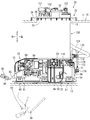
- the fuel supply device is installed in a fuel tank mounted on a vehicle such as an automobile equipped with an engine which is an internal combustion engine, and supplies the fuel in the fuel tank to the engine.
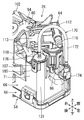
- 1 is a perspective view showing a fuel supply device
- FIG. 2 is a front view thereof
- FIG. 3 is a rear view thereof. 1 to 3, the front, rear, left, right, upper, and lower directions correspond to the respective directions of the vehicle. That is, the front-rear direction corresponds to the vehicle length direction, the left-right direction corresponds to the vehicle width direction, and the up-down direction corresponds to the vehicle height direction.
- the front-back direction and the left-right direction of the fuel supply device may be oriented in any directions.
- the fuel tank 10 is a hollow container having an upper wall portion 11 and a bottom wall portion 12. A circular hole-shaped opening 13 is formed in the upper wall 11.
- the upper wall portion 11 and the lower wall portion 12 are mounted on the vehicle with the upper wall portion 11 and the bottom wall portion 12 in a horizontal state.
- the fuel tank 10 is made of resin and deforms (mainly expands and contracts in the vertical direction) due to changes in tank internal pressure.
- gasoline as a liquid fuel is stored.
- the fuel supply device 20 includes a flange unit 22, a joint member 24, and a pump unit 26.
- a joint member 24 is connected to the flange unit 22 so as to be vertically movable.
- a pump unit 26 is connected to the joint member 24 so as to be vertically rotatable.
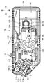
- the flange unit 22 includes a flange body 28.
- the flange main body 28 is mainly formed of a circular plate-shaped cover plate portion 32.
- the flange body 28 is made of resin.
- a short cylindrical fitting tube portion 33 is concentrically formed on the lower surface of the lid plate portion 32.
- An annular plate-shaped flange portion 34 is formed on the outer peripheral portion of the lid plate portion 32 so as to project radially outward from the fitting cylinder portion 33.
- the lid plate portion 32 is provided with a fuel discharge port 37, a first electric connector portion 38, and a second electric connector portion 39.
- the fuel discharge port 37 is formed in a straight tube shape that penetrates the lid plate portion 32 in the vertical direction. Further, a predetermined number of metal terminals are arranged in both electric connector parts 38, 39.
- a hollow container-shaped canister portion 150 is formed at the rear of the flange body 28.
- the outer shape of the canister portion 150 is formed in a substantially semi-cylindrical shape that is concentric with the flange body 28.
- An adsorbent e.g., activated carbon
- An evaporation port 151, an atmosphere port 152, and a purge port 153, which communicate with the inside of the canister portion 150, are formed on the upper surface of the flange body 28.
- a pair of left and right fixed side rails 155 that extend linearly in the vertical direction are formed symmetrically (see FIG. 2).
- the joint member 24 has a joint body 46, a spring guide 47, and a pair of left and right moving side rails 157.
- the joint body 46 is made of resin, and is formed in a vertically elongated strip plate shape that is flat in the front-rear direction and extends in the up-down direction.
- An engaging shaft hole 50 penetrating in the front-rear direction is formed in the lower portion of the joint body 46 (see FIG. 3).
- the spring guide 47 is formed in a pillar shape on the central portion of the joint body 46.
- Both moving-side rails 157 linearly extend in the up-and-down direction on both left and right sides of the upper portion of the joint member 24. Both moving side rails 157 are formed symmetrically on the joint body 46.
- the spring 52 which is a metal coil spring, is fitted into the spring guide 47 of the joint member 24.
- both moving side rails 157 of the joint member 24 are engaged with both fixed side rails 155 of the flange unit 22 so as to be vertically movable within a predetermined range. That is, the joint member 24 is connected to the flange unit 22 so as to be vertically movable. Further, the flange body 28 and the joint body 46 are urged in the separating direction by the elasticity of the spring 52.
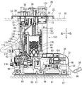
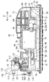
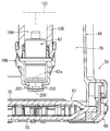
- the pump unit 26 includes a sub tank 54, a sender gauge 56, a fuel pump 58, a pump case 60, a pressure regulator 62, and a regulator case 64.
- FIG. 4 is a plan view showing the pump unit
- FIG. 5 is a front view showing the same with a part thereof cut away
- FIG. 6 is a perspective view showing the left side.
- the sender gauge 56 is omitted in FIGS. 4 and 5.
- the sub tank 54 includes a sub tank main body 66, a fuel filter 67, and a cover member 68.
- the sub tank main body 66 is made of resin and is formed in an inverted shallow box shape having an opening on the lower surface.
- the sub tank main body 66 is formed in a rectangular shape that extends in the left-right direction in plan view (see FIG. 4).
- a square opening hole 70 is formed at a position on the right side of the upper surface of the sub tank body 66.
- a substantially rectangular tubular fuel receiving tubular portion 71 extending upward is formed (see FIG. 6). The upper surface of the fuel receiving cylinder portion 71 is open.
- FIG. 7 is a side sectional view showing the fuel receiving cylinder portion.
- a hollow cylindrical guide cylinder portion 131 extending in the vertical direction is formed in the fuel receiving cylinder portion 71.
- the guide cylinder portion 131 is arranged in the left side portion of the fuel receiving cylinder portion 71.
- the lower surface of the guide tube portion 131 is opened at a position higher than the lower surface of the sub tank body 66.
- the guide cylinder portion 131 is integrally formed by utilizing a corner formed by the left side portion and the rear side portion of the fuel receiving cylinder portion 71.
- an engaging shaft 72 projecting rearward is formed at a position on the lower left side of the rear surface of the sub tank main body 66 (see FIG. 4).
- a plate-shaped standing wall portion 73 facing the front-rear direction is formed on the right rear portion of the upper surface portion of the sub tank body 66 (see FIG. 1).
- the fuel filter 67 includes a filter member 75, an inner frame member 76, and a connecting pipe 77.
- the filter member 75 is a member that filters fuel, and is formed in a hollow bag shape with a filter material made of a resin non-woven fabric.
- the outer shape of the filter member 75 is formed in a rectangular shape that is flat in the up-down direction and has the left-right direction as the longitudinal direction.
- the inner frame member 76 is made of resin and has a skeletal structure that holds the filter member 75 in a state of being swelled in the vertical direction.
- the connecting pipe 77 is made of resin and formed in a vertical circular tube shape.
- the connecting pipe 77 is joined to the right portion of the inner frame member 76 by heat welding.
- the upper surface of the filter member 75 is sandwiched between the inner frame member 76 and the connecting pipe 77.
- the inside and outside of the filter member 75 are communicated with each other via the connection pipe 77.
- the filter member 75 is arranged with respect to the sub tank main body 66 so as to close the lower surface opening thereof.
- a fuel storage space 79 for storing fuel is formed between the sub tank body 66 and the filter member 75.
- the connection pipe 77 is arranged in the opening hole 70 of the sub tank body 66.
- An annular space portion between the opening hole 70 and the connection pipe 77 serves as a fuel inlet 80.
- the fuel in the fuel tank 10 flows into the fuel storage space 79 from the inflow port 80 by its own weight.
- the cover member 68 is formed in a rectangular plate shape and a grid plate shape having a large number of openings.
- the cover member 68 is made of resin.
- the cover member 68 is attached to the sub tank main body 66 by a snap fit.
- the peripheral portion of the filter member 75 is sandwiched between the peripheral portions of the sub tank body 66 and the cover member 68.
- the cover member 68 covers the lower surface of the filter member 75.
- a large number of hemispherical projections 81 are dispersedly formed on the lower surface of the cover member 68.
- a predetermined space is set between the guide cylinder portion 131 of the sub tank main body 66 and the filter member 75.
- the sender gauge 56 includes a gauge body 84, an arm 85, and a float 86.
- the gauge body 84 is attached to the rear side surface of the standing wall portion 73 of the sub tank body 66.
- a base end of an arm 85 is attached to a rotating member 88 provided on the gauge body 84 so as to be rotatable around a horizontal axis.
- a float 86 is attached to the free end of the arm 85.
- the sender gauge 56 is a liquid level gauge that detects the remaining amount of fuel in the fuel tank 10, that is, the position of the liquid level.
- the fuel pump 58 is a substantially columnar electric fuel pump.
- the fuel pump 58 includes a motor unit and a pump unit, and sucks, pressurizes, and discharges fuel.
- the fuel pump 58 has a fuel inlet 90 at the end on the pump side (right end) and a fuel outlet 91 at the end on the motor side (left end).
- An electric connector is provided at the end of the fuel pump 58 on the motor side.
- a brushless DC motor for example, is used for the motor unit.
- the pump case 60 has a case body 94 formed in a hollow cylindrical shape extending in the left-right direction.
- the pump case 60 is made of resin.
- An end plate portion 95 that closes the one end side opening (left end side opening) of the case main body 94 is formed.
- a straight tubular discharge pipe portion 96 penetrating the end plate portion 95 is formed.
- a cylindrical connecting tube portion 100 protruding upward is formed at a position near the tip of the discharge pipe portion 96. The inside of the connecting tube portion 100 communicates with the inside of the discharge pipe portion 96.
- a passage that includes the internal passages of the discharge pipe portion 96 and the connecting cylinder portion 100 and through which the pressurized fuel discharged from the fuel pump 58 flows is referred to as a fuel passage 133.
- a leak passage forming member 170 is connected to the tip of the discharge pipe portion 96. The leak passage forming member 170 will be described later.
- the fuel pump 58 is housed in the case body 94 with the fuel discharge port 91 facing left.
- the fuel discharge port 91 is connected to a discharge port connection port 160 formed at the base end (right end) of the discharge pipe 96.
- a pair of front and rear elastic support pieces 102 extending in opposite directions are formed symmetrically in the front and rear directions at the upper end of the central portion of the case main body 94 in the axial direction.
- Both elastic support pieces 102 are strip-shaped and are formed in a substantially S shape in a plan view.
- the tip ends of both elastic support pieces 102 are attached to both front and rear sides of the sub tank main body 66 by snap fit.
- the pump case 60 is elastically supported by the elastic support pieces 102 on the sub tank main body 66 in a horizontal state, that is, in a horizontal state (see FIG. 5).
- a resin pump cap 104 that closes the right end opening surface of the case body 94 is attached by snap fitting.
- the pump cap 104 has a disc-shaped cap body 166.
- the cap body 166 is provided with an elbow tubular suction pipe portion 105.
- a fuel suction port 90 of the fuel pump 58 is connected to a suction port connection port 168 formed at one end (left end) of the suction pipe portion 105.
- the other end (lower end) of the suction pipe portion 105 is connected to the connection pipe 77 of the fuel filter 67.
- the suction pipe portion 105 is attached to the connection pipe 77 by a snap fit.
- the outer shape of the pressure regulator 62 is formed in a substantially columnar shape.
- the pressure regulator 62 adjusts the pressure of the pressurized fuel discharged from the fuel pump 58, that is, the pressure of the fuel supplied to the engine to a predetermined pressure, and discharges the surplus fuel.
- the regulator case 64 is made of resin and has a hollow cylindrical container shape.
- the regulator case 64 has a first case half body 112 and a second case half body 113 that are divided in the axial direction. Both case halves 112, 113 are attached to each other by a snap fit.
- the pressure regulator 62 is housed in the regulator case 64.
- the regulator case 64 is arranged in a horizontal position with the axial direction being horizontal.
- the first case half 112 is formed with a cylindrical connected tubular portion 115 projecting downward and a fuel discharge portion 116 projecting tangentially outward from the upper end portion.
- the connected tubular portion 115 and the fuel discharge portion 116 are in communication with the fuel introduction port of the pressure regulator 62 in the first case half 112.
- the second case half 113 is provided with a discharge pipe 118 that projects downward from the end opposite to the first case half 112.
- the discharge pipe portion 118 communicates with the surplus fuel discharge port of the pressure regulator 62 in the second case half body 113.
- the fuel discharger 116 discharges the fuel whose pressure is adjusted by the pressure regulator 62. Further, the surplus fuel in the pressure regulator 62 is discharged from the discharge pipe portion 118.
- the discharge pipe portion 118 is directed into the fuel receiving cylinder portion 71 of the sub tank body 66 (see FIG. 6).
- the connected tubular portion 115 of the regulator case 64 is fitted and connected to the connecting tubular portion 100 of the pump case 60.
- a check valve 120 is incorporated in the connecting cylinder part 100.
- the check valve 120 is a check valve for retaining the residual pressure that blocks the reverse flow of the pressurized fuel in the connecting tubular portion 100.
- the check valve 120 is closed by its own weight and opened by the fuel pressure.
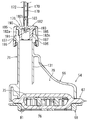
- FIG. 9 is a side view showing the leak passage forming member.
- the leak passage forming member 170 includes a leak tube 172, a first cap 174, and a second cap 176.
- the leak tube 172 and both caps 174 and 176 are made of resin.
- the leak tube 172 is made of a flexible tube.
- a series of leak passages 178 are formed by the leak tube 172 and the internal passages of the caps 174 and 176 (see FIGS. 7 and 8).
- the leak passage 178 is a passage for returning the pressurized fuel into the sub tank 54.
- the leak passage 178 corresponds to the “pressurized fuel return passage” in the present specification.
- the first cap 174 corresponds to the “upstream passage member” in the present specification.
- the second cap 176 corresponds to the “downstream passage member” in this specification.
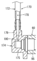
- FIG. 8 is a sectional view showing the tip of the discharge pipe of the pump case.
- the first cap 174 is formed in an elbow shape having a cylindrical cap portion 175 that closes the side end surface and a cylindrical connection port 179 that projects upward from the cap portion 175. .
- the cap portion 175 is formed so as to be connectable to the tip portion of the discharge pipe portion 96 of the pump case 60.
- the connection port 179 has an inner diameter smaller than the inner diameter of the cap portion 175.
- a throttle 180 that reduces the passage area is formed in the upstream end of the connection port 179.
- the throttle unit 180 limits the amount of pressurized fuel that leaks.
- One end of the leak tube 172 is press-fitted and connected to the connection port 179.
- the cap portion 175 is concentrically joined to the distal end portion of the discharge pipe portion 96 by welding.
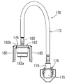
- the second cap 176 has a cap portion 182 and a connection port 183 concentrically.
- the cap portion 182 has a cylindrical tubular portion 182a and an end plate portion 182b that closes the upper end surface of the tubular portion 182a.
- the cap portion 182 is formed so that it can be fitted into the upper end opening of the guide tube portion 131 of the sub tank main body 66 and that the opening can be closed.
- the connection port 183 is formed in a cylindrical shape protruding upward from the central portion of the end plate portion 182b.
- the other end of the leak tube 172 is press-fitted and connected to the connection port 183.
- a pair of front and rear engaging pieces 185 having engaging holes 186 are formed on the outer peripheral portion of the end plate portion 182b of the cap portion 182.
- a pair of front and rear engaging protrusions 187 are formed on the outer surface of the upper end portion of the guide cylinder portion 131 of the sub tank main body 66.
- the second cap 176 is attached to the guide cylinder portion 131 of the sub tank body 66 by snap fitting. That is, by pressing the second cap 176 against the guide cylinder portion 131 from above, the engagement holes 186 are engaged with the engagement protrusions 187 by utilizing the elastic deformation of the engagement pieces 185.
- the tubular portion 182a of the cap portion 182 is fitted into the upper end opening of the guide tubular portion 131, and the upper end opening of the guide tubular portion 131 is opened by the end plate portion 182b. It is closed.
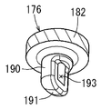
- FIG. 10 is a perspective view showing the diverting wall portion of the second cap. As shown in FIG. 10, the lower end opening of the extension cylinder 190 is covered by the diverting wall 191.
- a pressurizing fuel injection port 193 having a substantially vertically long rectangular shape is formed on one side of the extending tubular portion 190.
- the deflecting wall portion 191 is formed in a substantially 1/4 spherical shape.
- the turning wall portion 191 corresponds to the "wall member" in this specification.
- the discharge fuel pipe 124 is made of a flexible resin hose or the like.
- the first electrical connector portion 38 of the flange unit 22 and the electrical connector of the fuel pump 58 of the pump unit 26 are electrically connected via the first wire harness 126.
- the second electric connector portion 39 of the flange unit 22 and the gauge body 84 (see FIG. 3) of the pump unit 26 are electrically connected via the second wire harness 128.
- Both wire harnesses 126 and 128 are appropriately mounted on wiring hook portions integrally formed with the adjacent resin members.
- the fuel supply device 20 is in an extended state.
- the joint member 24 is suspended from the flange unit 22, and the pump unit 26 is suspended from the joint member 24. That is, the joint member 24 is lowered to the lowermost position (the most separated position) with respect to the flange unit 22. Further, the pump unit 26 is rotated (see the arrow Y1 in FIG. 3) to the right downward inclined state (see the chain double-dashed line 26 in FIG. 3) with respect to the joint member 24.
- the pump unit 26 is inserted into the opening 13 of the fuel tank 10 from above with the fuel supply device 20 in the extended state.
- the pump unit 26 is rotated with respect to the joint member 24 in a direction opposite to the suspension state (see arrow Y2 in FIG. 3) to be in a horizontal state and mounted on the bottom wall portion 12 of the fuel tank 10. (See FIGS. 2 and 3).
- a rotation limiting mechanism that limits the rotation of the pump unit 26 above the horizontal state is provided between the joint member 24 and the pump unit 26.
- the flange unit 22 is pushed down against the urging force of the spring 52, so that the canister portion 150 is fitted into the opening 13 of the fuel tank 10.
- the flange portion 34 of the flange main body 28 is fixed to the upper wall portion 11 of the fuel tank 10 through fixing means (not shown) such as fixing metal fittings and bolts (see FIGS. 2 and 3).
- fixing means such as fixing metal fittings and bolts (see FIGS. 2 and 3).
- the flange unit 22 closes the opening 13 of the fuel tank 10.
- a fuel supply pipe connected to the engine is connected to the fuel discharge port 37 of the flange unit 22. Further, external connectors are connected to the first electric connector portion 38 and the second electric connector portion 39, respectively. Further, the evaporation port 151 is connected to an evaporated fuel passage connected to the breather pipe of the fuel tank 10. Further, the atmosphere port 152 is open to the atmosphere. Further, the purge port 153 is connected to a purge passage connected to an intake passage of the engine.
- the pump unit 26 In the installed state of the fuel supply device 20 (see FIGS. 2 and 3), the pump unit 26 is held in a state of being pressed against the bottom wall portion 12 of the fuel tank 10 by the urging force of the spring 52. Further, the protrusion 81 of the cover member 68 abuts on the bottom wall portion 12 of the fuel tank 10, whereby the fuel flow between the cover member 68 and the bottom wall portion 12 is secured.
- the fuel tank 10 deforms, that is, expands and contracts due to changes in the tank internal pressure due to changes in temperature, changes in fuel amount, and the like.
- the distance between the upper wall portion 11 and the bottom wall portion 12 of the fuel tank 10 changes (increases or decreases).
- the flange unit 22 and the joint member 24 move in the vertical direction relatively to follow the change in the height of the fuel tank 10.
- the fuel pump 58 is driven by driving power from the outside. Then, the fuel from the inside of the fuel tank 10 via the cover member 68 and / or the fuel in the fuel storage space 79 of the pump unit 26 is sucked into the fuel pump 58 via the fuel filter 67 and pressurized.
- the pressurized fuel discharged from the fuel pump 58 flows into the regulator case 64 via the discharge pipe portion 96 of the pump case 60 and is pressure-controlled by the pressure regulator 62.
- the regulated pressurized fuel is supplied to the engine from the fuel discharge port 37 of the flange unit 22 via the discharge fuel pipe 124.
- the surplus fuel due to the pressure regulation of the pressure regulator 62 is discharged from the discharge pipe portion 118 of the regulator case 64 into the fuel receiving cylinder portion 71 of the sub tank body 66. Further, the evaporated fuel generated in the fuel tank 10 is introduced into the canister portion 150 from the evaporated fuel passage via the evaporation port 151. Further, the evaporated fuel in the canister portion 150 is purged into the intake passage via the purge passage by the intake negative pressure. Further, when the evaporated fuel in the canister unit 150 is purged, the atmosphere is introduced into the canister unit 150.
- a part of the pressurized fuel discharged from the fuel pump 58 to the fuel passage 133 in the discharge pipe portion 96 of the pump case 60 receives the fuel of the sub tank main body 66 through the leak passage 178 of the leak passage forming member 170. It is discharged into the cylindrical portion 71.
- the throttle portion 180 of the first cap 174 limits the amount of the pressurized fuel that leaks.
- the pressurized fuel that has flowed into the connecting port 183 of the second cap 176 and extends downwardly into the tubular portion 190 is deflected by approximately 90 ° by the deflection wall portion 191 and the pressurized fuel jet port 193.
- a concave arc-shaped wall portion of the tubular portion 182a facing the pressurized fuel jet port 193 is referred to as a facing wall 182c.
- the flow of the pressurized fuel ejected from the leak passage 178 is diverted by the diverting wall portion 191 of the second cap 176, so that the fuel filter 67 is applied to the upper surface of the filter member 75. Direct collision of pressurized fuel can be avoided. Thereby, the deformation of the filter member 75 of the fuel filter 67 due to the pressurized fuel ejected from the leak passage 178 can be suppressed.
- the deflecting wall portion 191 of the second cap 176 is not provided, the flow of the pressurized fuel ejected from the leak passage 178 is directly below the extending tubular portion 190 of the second cap 176. Are jetted out to directly collide with the upper surface of the filter member 75. Therefore, the upper surface of the filter member 75 may be deformed into a concave shape.
- the deflecting wall portion 191 in the extension tubular portion 190 by providing the deflecting wall portion 191 in the extension tubular portion 190, direct collision of the pressurized fuel with the upper surface of the filter member 75 is avoided, and the deformation of the filter member 75 is avoided. Can be suppressed.
- the pressurized fuel that has flowed through the leak passage 178 is diverted by the diverting wall portion 191 of the second cap 176 and ejected from the pressurized fuel ejection port 193. Thereby, direct collision of the pressurized fuel with the upper surface of the filter member 75 of the fuel filter 67 can be avoided.
- the second cap 176 is integrally formed with the deflecting wall portion 191 and the pressurized fuel jet port 193. Therefore, the structure of the second cap 176 having the diverting wall portion 191 and the pressurized fuel injection port 193 can be simplified and the cost can be reduced.
- the second cap 176 is provided with a concave arc-shaped facing wall 182c facing the pressurized fuel jet port 193. Therefore, the pressurized fuel ejected from the pressurized fuel ejection port 193 collides with the facing wall 182c of the second cap 176. As a result, the flow of the pressurized fuel can be changed and the flow velocity can be reduced.
- the amount of fuel leaking can be limited by the throttle portion 180 provided on the first cap 174.
- FIG. 11 is a sectional view showing the peripheral portion of the pressure regulator.
- the sub-tank main body 66 of the sub-tank 54 is provided with a fuel outlet pipe portion 195 extending in the vertical direction.
- a fuel outlet passage 196 is formed in the fuel outlet pipe portion 195.
- the fuel outlet passage 196 is a branch passage branched from the fuel passage 133 and is a passage for returning the pressurized fuel into the sub tank 54.
- the fuel outlet passage 196 corresponds to the “pressurized fuel return passage” in the present specification.
- a pressure regulator 62 is fitted to the lower end of the fuel outlet passage 196.
- the pressure regulator 62 adjusts the pressure in the fuel derivation passage 196 to a predetermined pressure, and ejects the surplus fuel directly below the surplus fuel discharge port 62a.
- the pressure regulator 62 is normally submerged in the fuel stored in the fuel storage space 79.
- the fuel outlet pipe portion 195 corresponds to the “outlet passage forming member” in the present specification.
- a resin retaining member 198 for retaining the pressure regulator 62 is attached to the lower end of the fuel outlet passage 196 by snap fit.
- the retaining member 198 is formed in a bottomed cylindrical shape that covers the lower half of the pressure regulator 62 with a predetermined gap.
- a bottomed cylindrical deflection wall portion 200 facing the surplus fuel outlet 62a is formed.
- a plurality of (two in FIG. 11) pressurized fuel injection ports 202 are formed on the side wall of the diverting wall portion 200.
- the pressurized fuel ejected from the excess fuel discharge port 62a of the pressure regulator 62 is deflected by approximately 90 ° by the bottom wall of the deflection wall portion 200, and ejected laterally from the pressurized fuel ejection port 202 ( (See arrow in FIG. 11).
- the turning wall portion 200 corresponds to the "wall member" in this specification.
- the deflecting wall portion 200 of the retaining member 198 is cut off as an opening hole, the flow of the pressurized fuel ejected directly below from the surplus fuel discharge port 62a is the filter member 75. Directly hit the top surface of. Therefore, the upper surface of the filter member 75 may be deformed into a concave shape.
- the second embodiment by providing the deflecting wall portion 200 on the retaining member 198, direct collision of the pressurized fuel with the upper surface of the filter member 75 is avoided, and the filter member 75 is not deformed. Can be suppressed.
- the technology disclosed in the present specification has been described above with respect to the specific embodiment, the technology can be implemented in various other modes.
- the technology of the present disclosure is not limited to the fuel supply device 20 of a vehicle such as an automobile, but may be applied to other fuel supply devices.
- the wall member may be provided separately from the downstream passage member or the outlet passage forming member. In this case, the pressurized fuel ejected from the pressurized fuel ejection port collides with the wall member and is deflected.
- a part of the tubular portion 182a of the cap portion 182 of the second cap 176 is the facing wall 182c, but a dedicated facing wall other than the tubular portion 182a may be formed on the second cap 176.
- a first aspect is a fuel supply device for supplying fuel in a fuel tank to an internal combustion engine, wherein a fuel pump, a sub tank for storing the fuel, and a part of the pressurized fuel discharged from the fuel pump are
- the fuel tank includes a pressurized fuel return passage for returning to the inside of the sub tank, and a fuel filter provided at the bottom of the sub tank and having a bag-shaped filter member for filtering fuel sucked into the fuel pump.
- the fuel supply device includes a wall member that diverts the flow of the pressurized fuel so that the pressurized fuel ejected from the return passage does not collide with the filter member.
- the flow of the pressurized fuel ejected from the pressurized fuel return passage is diverted by the wall member, so that the direct collision of the pressurized fuel with the filter member of the fuel filter can be avoided. it can. Accordingly, the deformation of the filter member of the fuel filter due to the pressurized fuel ejected from the pressurized fuel return passage can be suppressed.
- a second aspect is the fuel supply device according to the first aspect, wherein the pressurized fuel return passage is a leak passage for leaking a part of the pressurized fuel discharged from the fuel pump.
- a downstream passage member that forms a downstream end portion of the downstream passage member, the wall member is formed on the downstream passage member, and the downstream passage member is deflected by the wall member.
- a pressurized fuel ejection port for ejecting the pressurized fuel is formed.
- the flow of the pressurized fuel that has flowed through the leak passage is diverted by the wall member of the downstream passage member, and is ejected from the pressurized fuel ejection port.
- direct collision of the pressurized fuel with the filter member of the fuel filter can be avoided.
- a third aspect is the fuel supply device according to the second aspect, wherein the wall member and the pressurized fuel injection port are integrally formed in the downstream passage member.
- the third aspect it is possible to simplify the structure of the downstream passage member having the wall member and the pressurized fuel ejection port, and reduce the cost.
- a fourth aspect is the fuel supply device according to the second or third aspect, wherein the downstream passage member includes a concave arcuate facing wall that faces the pressurized fuel jet port.
- the pressurized fuel ejected from the pressurized fuel ejection port collides with the facing wall of the downstream passage member. As a result, the flow of the pressurized fuel can be changed and the flow velocity can be reduced.
- a fifth aspect is the fuel supply device according to the first or second aspect, including an upstream passage member that forms an upstream end of the leak passage, and the upstream passage member leaks.
- a throttle portion that limits the amount of fuel is provided.
- the leaked fuel amount can be limited by the throttle portion provided in the upstream passage member.
- a sixth aspect is the fuel supply device according to the first aspect, wherein the pressurized fuel return passage is a fuel outlet passage for deriving a part of the pressurized fuel discharged from the fuel pump, A lead-out passage forming member that forms a lead-out passage is provided, and the lead-out passage forming member is provided with a pressure regulator that adjusts the pressure of the pressurized fuel and discharges excess pressurized fuel.
- a retaining member for retaining the pressure regulator is attached to the lead-out passage forming member, the wall member is formed in the retaining member, and the retaining member is formed by the wall member.
- a pressurized fuel ejection port for ejecting the deflected pressurized fuel is formed.
- the pressurized fuel ejected from the pressure regulator provided at the downstream end of the fuel outlet passage can be made to collide with the wall member of the retaining member. As a result, direct collision of the pressurized fuel with the filter member of the fuel filter can be avoided.
Landscapes
- Engineering & Computer Science (AREA)
- Chemical & Material Sciences (AREA)
- Combustion & Propulsion (AREA)
- Mechanical Engineering (AREA)
- General Engineering & Computer Science (AREA)
- Cooling, Air Intake And Gas Exhaust, And Fuel Tank Arrangements In Propulsion Units (AREA)
Abstract
Description
本開示は、燃料供給装置に関する。 The present disclosure relates to a fuel supply device.
WO2017/141628は従来型の燃料供給装置を開示する。この燃料供給装置は、燃料ポンプとサブタンクとリーク通路と燃料フィルタとを備える。燃料ポンプは、燃料タンク内の燃料を吸入しかつ昇圧した後に吐出する。サブタンクは燃料を貯留する。リーク通路は、燃料ポンプから吐出された加圧燃料の一部をサブタンク内に戻す。燃料フィルタは、サブタンクの底部に設けられかつ燃料ポンプに吸入される燃料を濾過する袋状のフィルタ部材を有する。リーク通路からフィルタ部材に向けて加圧燃料が噴出される。 WO2017 / 141628 discloses a conventional fuel supply device. This fuel supply device includes a fuel pump, a sub tank, a leak passage, and a fuel filter. The fuel pump sucks the fuel in the fuel tank, boosts the pressure, and then discharges the fuel. The sub tank stores fuel. The leak passage returns a part of the pressurized fuel discharged from the fuel pump into the sub tank. The fuel filter has a bag-shaped filter member that is provided at the bottom of the sub-tank and filters the fuel drawn into the fuel pump. Pressurized fuel is ejected from the leak passage toward the filter member.
WO2017/141628の燃料供給装置によると、リーク通路からフィルタ部材に向けて噴出された燃料により、フィルタ部材が凹状に変形するおそれがある。 According to the fuel supply device of WO2017 / 141628, the fuel ejected from the leak passage toward the filter member may deform the filter member into a concave shape.
本開示の課題は、加圧燃料戻し通路から噴出された加圧燃料による燃料フィルタのフィルタ部材の変形を抑制することにある。 The problem of the present disclosure is to suppress the deformation of the filter member of the fuel filter due to the pressurized fuel ejected from the pressurized fuel return passage.
前記した課題は、次の手段により解決される。 The above-mentioned problems can be solved by the following means.
本開示の一つの手段は、燃料タンク内の燃料を内燃機関へ供給する燃料供給装置であって、燃料ポンプと、燃料を貯留するサブタンクと、前記燃料ポンプから吐出された加圧燃料の一部を前記サブタンク内に戻す加圧燃料戻し通路と、前記サブタンクの底部に設けられかつ前記燃料ポンプに吸入される燃料を濾過する袋状のフィルタ部材を有する燃料フィルタと、を備えており、前記加圧燃料戻し通路から噴出される加圧燃料が前記フィルタ部材に衝突しないように、該加圧燃料の流れを変向する壁部材を備えた、燃料供給装置である。 One means of the present disclosure is a fuel supply device for supplying the fuel in a fuel tank to an internal combustion engine, the fuel pump, a sub-tank for storing the fuel, and a part of the pressurized fuel discharged from the fuel pump. And a fuel filter having a bag-shaped filter member provided at the bottom of the sub-tank for filtering the fuel sucked into the fuel pump. The fuel supply device includes a wall member that diverts the flow of the pressurized fuel so that the pressurized fuel ejected from the pressurized fuel return passage does not collide with the filter member.
前記手段によれば、加圧燃料戻し通路から噴出される加圧燃料の流れが壁部材により変向されることにより、燃料フィルタのフィルタ部材に対する加圧燃料の直接衝突を回避することができる。これによって、加圧燃料戻し通路から噴出された加圧燃料による燃料フィルタのフィルタ部材の変形を抑制することができる。 According to the above means, the flow of the pressurized fuel ejected from the pressurized fuel return passage is diverted by the wall member, so that the direct collision of the pressurized fuel with the filter member of the fuel filter can be avoided. Accordingly, the deformation of the filter member of the fuel filter due to the pressurized fuel ejected from the pressurized fuel return passage can be suppressed.
以下、実施形態を図面に基づいて説明する。 Embodiments will be described below with reference to the drawings.
[第1実施形態]
第1実施形態にかかる燃料供給装置は、内燃機関であるエンジンを搭載する自動車等の車両に搭載された燃料タンクに設置され、その燃料タンク内の燃料をエンジンへ供給するものである。図1は燃料供給装置を示す斜視図、図2は同じく正面図、図3は同じく背面図である。図1~図3において、前後左右上下の各方位は、車両の各方位に対応する。すなわち、前後方向は車長方向に対応し、左右方向は車幅方向に対応し、上下方向は車高方向に対応する。なお、燃料供給装置の前後方向及び左右方向については任意の方向に向けてもよい。
[First Embodiment]
The fuel supply device according to the first embodiment is installed in a fuel tank mounted on a vehicle such as an automobile equipped with an engine which is an internal combustion engine, and supplies the fuel in the fuel tank to the engine. 1 is a perspective view showing a fuel supply device, FIG. 2 is a front view thereof, and FIG. 3 is a rear view thereof. 1 to 3, the front, rear, left, right, upper, and lower directions correspond to the respective directions of the vehicle. That is, the front-rear direction corresponds to the vehicle length direction, the left-right direction corresponds to the vehicle width direction, and the up-down direction corresponds to the vehicle height direction. The front-back direction and the left-right direction of the fuel supply device may be oriented in any directions.
(燃料タンク)
図2に示すように、燃料タンク10は、上壁部11及び底壁部12を有する中空の容器である。上壁部11には、円形孔状の開口部13が形成されている。燃料タンク10は、上壁部11及び低壁部12が車両に対して上壁部11及び底壁部12を水平状態として搭載されている。燃料タンク10は、樹脂製であり、タンク内圧の変化によって変形(主に上下方向に膨張及び収縮)する。燃料タンク10内には、例えば、液体燃料としてのガソリンが貯留されている。
(Fuel tank)
As shown in FIG. 2, the
(燃料供給装置)
図1に示すように、燃料供給装置20は、フランジユニット22、ジョイント部材24及びポンプユニット26を備える。フランジユニット22にジョイント部材24が上下方向に移動可能に連結されている。ジョイント部材24にポンプユニット26が上下方向に回動可能に連結されている。
(Fuel supply device)
As shown in FIG. 1, the
(フランジユニット22)
フランジユニット22はフランジ本体28を備える。フランジ本体28は、円形板状の蓋板部32を主体として形成されている。フランジ本体28は樹脂製である。図2に示すように、蓋板部32の下面には、短円筒状の嵌合筒部33が同心状に形成されている。蓋板部32の外周部には、嵌合筒部33よりも径方向外方へ張り出す円環板状のフランジ部34が形成されている。
(Flange unit 22)
The
図1に示すように、蓋板部32には、燃料吐出ポート37、第1電気コネクタ部38及び第2電気コネクタ部39が設けられている。燃料吐出ポート37は、蓋板部32を上下方向に貫通する直管状に形成されている。また、両電気コネクタ部38,39内には、所定の本数の金属製端子が配置されている。
As shown in FIG. 1, the
フランジ本体28の後部には、中空容器状のキャニスタ部150が形成されている。キャニスタ部150の外形は、フランジ本体28と同心状をなす略半円筒形状に形成されている。キャニスタ部150内には、燃料タンク10内で発生した蒸発燃料を吸着、脱離可能な吸着材(例えば、活性炭)が収納されている。フランジ本体28の上面には、キャニスタ部150内に連通するエバポポート151、大気ポート152及びパージポート153が形成されている。また、キャニスタ部150の前側には、上下方向に直線状に延在する左右一対の固定側レール155が左右対称状に形成されている(図2参照)。
A hollow container-
(ジョイント部材24)
図2に示すように、ジョイント部材24は、ジョイント本体46、スプリングガイド47及び左右一対の移動側レール157を有する。ジョイント本体46は、樹脂製であり、前後方向に扁平をなしかつ上下方向に延在する縦長帯板状に形成されている。ジョイント本体46の下部には、前後方向に貫通する係合軸孔50が形成されている(図3参照)。また、スプリングガイド47は、ジョイント本体46の中央部上に支柱状に形成されている。また、両移動側レール157は、ジョイント部材24の上部の左右両側部において上下方向に直線状に延在している。両移動側レール157は、ジョイント本体46に左右対称状に形成されている。
(Joint member 24)
As shown in FIG. 2, the
(フランジユニット22に対するジョイント部材24の組み付け)
ジョイント部材24のスプリングガイド47には、金属製のコイルスプリングからなるスプリング52が嵌合される。この状態で、フランジユニット22の両固定側レール155に対して、ジョイント部材24の両移動側レール157が上下方向に所定の範囲内で移動可能に係合されている。すなわち、フランジユニット22にジョイント部材24が上下方向に移動可能に連結されている。また、フランジ本体28とジョイント本体46とは、スプリング52の弾性によって離間方向へ付勢されている。
(Assembling the
The
(ポンプユニット26)
図2に示すように、ポンプユニット26は、サブタンク54、センダゲージ56、燃料ポンプ58、ポンプケース60、プレッシャレギュレータ62及びレギュレータケース64を有する。図4はポンプユニットを示す平面図、図5は同じく一部破断して示す正面図、図6は同じく左側部を示す斜視図である。なお、図4及び図5においてセンダゲージ56は省略されている。
(Pump unit 26)
As shown in FIG. 2, the
(サブタンク54)
図5に示すように、サブタンク54は、サブタンク本体66と燃料フィルタ67とカバー部材68とを備えている。
(Sub tank 54)
As shown in FIG. 5, the
(サブタンク本体66)
サブタンク本体66は、樹脂製であり、下面を開口する逆浅箱状に形成されている。サブタンク本体66は、平面視で左右方向を長くする長四角形状に形成されている(図4参照)。サブタンク本体66の上面部の右寄りの位置には、四角形状の開口孔70が形成されている。サブタンク本体66の上面部の左後部には、上方へ延在する略角筒状の燃料受け入れ筒部71が形成されている(図6参照)。燃料受け入れ筒部71の上面は開口されている。
(Sub tank body 66)
The sub tank
図7は燃料受け入れ筒部を示す側断面図である。図7に示すように、燃料受け入れ筒部71内には、上下方向に延在する中空円筒状のガイド筒部131が形成されている。ガイド筒部131は、燃料受け入れ筒部71の左側部内に配置されている。ガイド筒部131の下面は、サブタンク本体66の下面より高い位置で開口されている。ガイド筒部131は、燃料受け入れ筒部71の左側部と後側部とのなす隅角部を利用して一体形成されている。
FIG. 7 is a side sectional view showing the fuel receiving cylinder portion. As shown in FIG. 7, in the fuel receiving
図3に示すように、サブタンク本体66の後面下部の左寄りの位置には、後方(紙面表方向)へ突出する係合軸72が形成されている(図4参照)。また、サブタンク本体66の上面部の右後部上には、前後方向に面する板状の立壁部73が形成されている(図1参照)。
As shown in FIG. 3, an engaging
(燃料フィルタ67)
図5に示すように、燃料フィルタ67は、フィルタ部材75と内骨部材76と接続管77とを備える。フィルタ部材75は、燃料を濾過する部材であり、樹脂製の不織布からなる濾材により中空袋状に形成されてなる。フィルタ部材75の外形は、上下方向に扁平でかつ左右方向を長手方向とする長四角形状に形成されている。
(Fuel filter 67)
As shown in FIG. 5, the
内骨部材76は、樹脂製であり、フィルタ部材75を上下方向に膨らんだ状態に保持する骨格構造を有する。また、接続管77は、樹脂製であり、縦型円管状に形成されている。接続管77は、内骨部材76の右部上に熱溶着により結合されている。内骨部材76と接続管77との間には、フィルタ部材75の上面部が挟持されている。接続管77を介してフィルタ部材75内外が連通されている。
The
フィルタ部材75は、サブタンク本体66に対してその下面開口を閉鎖するように配置されている。サブタンク本体66とフィルタ部材75との間には、燃料を貯留する燃料貯留空間79が形成されている。接続管77は、サブタンク本体66の開口孔70内に配置されている。開口孔70と接続管77との間の環状空間部は、燃料の流入口80とされている。燃料タンク10(図2参照)内の燃料は、自重により流入口80から燃料貯留空間79に流入する。
The
カバー部材68は、長四角形板状でかつ多数の開口を有する格子板状に形成されている。カバー部材68は、樹脂製である。カバー部材68は、サブタンク本体66にスナップフィットにより取り付けられている。サブタンク本体66とカバー部材68との周縁部の相互間には、フィルタ部材75の周縁部が挟持されている。カバー部材68は、フィルタ部材75の下面部を覆っている。カバー部材68の下面には、多数の半球状の突起部81が分散的に形成されている。
The
図7に示すように、サブタンク本体66のガイド筒部131とフィルタ部材75との間には所定の間隔が設定されている。
As shown in FIG. 7, a predetermined space is set between the
(センダゲージ56)
図3に示すように、センダゲージ56は、ゲージ本体84、アーム85及びフロート86を備える。ゲージ本体84は、サブタンク本体66の立壁部73の後側面に取り付けられている。ゲージ本体84に水平軸回りに回動可能に設けられた回動部材88には、アーム85の基端部が取り付けられている。アーム85の自由端部には、フロート86が取り付けられている。センダゲージ56は、燃料タンク10内の燃料の残量すなわち液面の位置を検出する液面計である。
(Sender gauge 56)
As shown in FIG. 3, the
(燃料ポンプ58)
図5に示すように、燃料ポンプ58は、略円柱形状の電動式燃料ポンプである。燃料ポンプ58は、モータ部とポンプ部とを備えており、燃料を吸入しかつ加圧して吐出する。燃料ポンプ58は、ポンプ部側の端部(右端部)に燃料吸入口90を有し、モータ部側の端部(左端部)に燃料吐出口91を有する。なお、燃料ポンプ58のモータ部側の端部に電気コネクタが設けられている。モータ部には、例えば、ブラシレス直流モータが用いられている。
(Fuel pump 58)
As shown in FIG. 5, the
(ポンプケース60)
ポンプケース60は、左右方向に延在する中空円筒状に形成されたケース本体94を有する。ポンプケース60は樹脂製である。ケース本体94の一端側開口(左端側開口)には、その開口を閉鎖する端板部95が形成されている。端板部95の中央部には、端板部95を貫通する直管状の吐出管部96が形成されている。また、吐出管部96の先端部寄りの位置には、上方へ突出する円筒状の接続筒部100が形成されている。接続筒部100内は、吐出管部96内と連通されている。
(Pump case 60)
The
吐出管部96及び接続筒部100の内部通路を含みかつ燃料ポンプ58から吐出された加圧燃料が流れる通路を燃料通路133という。また、吐出管部96の先端部にはリーク通路形成部材170が接続されている。リーク通路形成部材170は後で説明する。
A passage that includes the internal passages of the
ケース本体94内には、燃料ポンプ58が燃料吐出口91を左方に向けた状態で収容されている。燃料吐出口91は、吐出管部96の基端部(右端部)に形成された吐出口接続口160に接続されている。
The
図4に示すように、ケース本体94の軸方向の中央部の上端部には、相反方向へ延在する前後一対の弾性支持片102が前後対称状に形成されている。両弾性支持片102は、帯板状で、平面視で略S字状に形成されている。両弾性支持片102の先端部は、サブタンク本体66の前後の両側部にスナップフィットにより取り付けられている。両弾性支持片102によって、ポンプケース60がサブタンク本体66上に水平状態いわゆる横置き状態で弾性的に支持されている(図5参照)。
As shown in FIG. 4, a pair of front and rear
図5に示すように、ケース本体94には、その右端開口面を閉鎖する樹脂製のポンプ用キャップ104がスナップフィットにより取り付けられている。ポンプ用キャップ104は、円板状のキャップ本体166を有する。キャップ本体166には、エルボ管状の吸入管部105が形成されている。吸入管部105の一端部(左端部)に形成された吸入口接続口168には、燃料ポンプ58の燃料吸入口90が接続されている。吸入管部105の他端部(下端部)は、燃料フィルタ67の接続管77に接続されている。吸入管部105は、接続管77にスナップフィットにより取り付けられている。
As shown in FIG. 5, a
(プレッシャレギュレータ62)
図5に示すように、プレッシャレギュレータ62の外形は、略円柱形状に形成されている。プレッシャレギュレータ62は、燃料ポンプ58から吐出された加圧燃料すなわちエンジンに供給される燃料の圧力を所定の圧力に調整し、余剰となった燃料を排出する。
(Pressure regulator 62)
As shown in FIG. 5, the outer shape of the
(レギュレータケース64)
レギュレータケース64は、樹脂製であり、中空円筒型の容器形状に形成されている。レギュレータケース64は、軸方向に分割された第1ケース半体112及び第2ケース半体113を有する。両ケース半体112,113は、互いにスナップフィットにより取り付けられている。レギュレータケース64内には、プレッシャレギュレータ62が収容されている。レギュレータケース64は、軸方向を水平状態とする横置き状態で配置されている。
(Regulator case 64)
The
第1ケース半体112には、下方へ突出する円筒状の被接続筒部115、及び、上端部から接線方向外方へ突出する燃料吐出部116が形成されている。被接続筒部115及び燃料吐出部116は、第1ケース半体112内においてプレッシャレギュレータ62の燃料導入口と連通されている。
The
第2ケース半体113には、第1ケース半体112とは反対側の端部から下方へ突出する排出管部118が形成されている。排出管部118は、第2ケース半体113内においてプレッシャレギュレータ62の余剰燃料排出口と連通されている。燃料吐出部116は、プレッシャレギュレータ62で調圧された燃料を吐出する。また、プレッシャレギュレータ62で余剰となった燃料は、排出管部118から排出される。排出管部118は、サブタンク本体66の燃料受け入れ筒部71内に向けられている(図6参照)。
The
レギュレータケース64の被接続筒部115は、ポンプケース60の接続筒部100に嵌合接続されている。接続筒部100内には逆止弁120が組み込まれている。逆止弁120は、接続筒部100内の加圧燃料の逆流を阻止する残圧保持用の逆止弁である。逆止弁120は、自重により閉弁し、燃圧により開弁する。
The connected
(リーク通路形成部材170)
図9はリーク通路形成部材を示す側面図である。リーク通路形成部材170は、リーク用チューブ172と第1キャップ174と第2キャップ176とを有する。リーク用チューブ172及び両キャップ174,176はいずれも樹脂製である。リーク用チューブ172は、可撓性を有するチューブからなる。また、リーク用チューブ172及び両キャップ174,176の各内部通路により一連のリーク通路178が形成されている(図7及び図8参照)。リーク通路178は加圧燃料をサブタンク54内に戻す通路である。リーク通路178は本明細書でいう「加圧燃料戻し通路」に相当する。第1キャップ174は本明細書でいう「上流側通路部材」に相当する。第2キャップ176は本明細書でいう「下流側通路部材」に相当する。
(Leak passage forming member 170)
FIG. 9 is a side view showing the leak passage forming member. The leak
図8はポンプケースの吐出管部の先端部を示す断面図である。図8に示すように、第1キャップ174は、側端面を閉鎖する円筒状のキャップ部175と、キャップ部175から上方へ突出する円筒状の接続ポート179とを有するエルボ状に形成されている。キャップ部175は、ポンプケース60の吐出管部96の先端部に接続可能に形成されている。接続ポート179は、キャップ部175の内径よりも小さい内径を有する。接続ポート179の上流側端部内には、通路面積を小さくする絞り部180が形成されている。絞り部180は、リークする加圧燃料の燃料量を制限する。接続ポート179には、リーク用チューブ172の一端部が圧入により接続されている。キャップ部175は、吐出管部96の先端部に同心状に溶着によって結合されている。
FIG. 8 is a sectional view showing the tip of the discharge pipe of the pump case. As shown in FIG. 8, the
図7に示すように、第2キャップ176は、キャップ部182と接続ポート183とを同心状に有している。キャップ部182は、円筒状の筒部182aと、筒部182aの上端面を閉鎖する端板部182bと、を有する。キャップ部182は、サブタンク本体66のガイド筒部131の上端開口部に嵌合可能にかつその開口を閉鎖可能に形成されている。接続ポート183は、端板部182bの中央部から上方へ突出する円筒状に形成されている。接続ポート183には、リーク用チューブ172の他端部が圧入により接続されている。
As shown in FIG. 7, the
キャップ部182の端板部182bの外周部には、係合孔186を有する前後一対の係合片185が形成されている。一方、サブタンク本体66のガイド筒部131の上端部の外側面には、前後一対の係合突起187が形成されている。
A pair of front and rear engaging
第2キャップ176は、サブタンク本体66のガイド筒部131にスナップフィットにより取付けられている。すなわち、ガイド筒部131にその上方から第2キャップ176を押し付けることによって、両係合突起187に対して両係合片185の弾性変形を利用して係合孔186が係合されている。ガイド筒部131に第2キャップ176が取付けられることによって、キャップ部182の筒部182aがガイド筒部131の上端開口部に嵌合されるとともに端板部182bによりガイド筒部131の上端開口が閉鎖されている。
The
接続ポート183の下端部には、キャップ部182の端板部182bの中央部から下方へ突出する円筒状の延出筒部190が形成されている。図10が第2キャップの変向壁部を示す斜視図である。図10に示すように、延出筒部190の下端開口部は変向壁部191により覆われている。延出筒部190の一側には略縦長四角形状の加圧燃料噴出口193が形成されている。変向壁部191は、略1/4球面状に形成されている。変向壁部191は本明細書でいう「壁部材」に相当する。
At the lower end of the
(フランジユニット22に対するポンプユニット26の組み付け)
図3に示すように、フランジユニット22に連結されたジョイント本体46の係合軸孔50にサブタンク本体66の係合軸72が回動可能に係合される。これにより、ジョイント部材24にポンプユニット26が上下方向(図3中、矢印Y1,Y2方向参照)に回動可能に連結されている。
(Assembling the
As shown in FIG. 3, the
図2に示すように、フランジユニット22の燃料吐出ポート37とポンプユニット26のレギュレータケース64の燃料吐出部116とは、吐出燃料配管124を介して接続される。吐出燃料配管124は、可撓性を有する樹脂製のホース等からなる。
As shown in FIG. 2, the
フランジユニット22の第1電気コネクタ部38とポンプユニット26の燃料ポンプ58の電気コネクタとは、第1ワイヤハーネス126を介して電気的に接続される。フランジユニット22の第2電気コネクタ部39とポンプユニット26のゲージ本体84(図3参照)とは、第2ワイヤハーネス128を介して電気的に接続される。なお、両ワイヤハーネス126,128は、隣接する樹脂部材に一体成形された配線フック部に適宜掛装される。
The first
(燃料供給装置20の設置)
燃料タンク10への組み付けに際して、燃料供給装置20が伸長状態とされる。この状態では、フランジユニット22にジョイント部材24が懸吊され、ジョイント部材24にポンプユニット26が懸吊される。すなわち、ジョイント部材24がフランジユニット22に対する最下位置(最離間位置)に下降される。また、ポンプユニット26がジョイント部材24に対する右下がりの傾斜状態(図3中、二点鎖線26参照)に回動(図3中、矢印Y1参照)される。
(Installation of fuel supply device 20)
At the time of assembling to the
次に、燃料供給装置20の伸長状態のまま、ポンプユニット26を燃料タンク10の開口部13内にその上方から挿入させる。ポンプユニット26は、ジョイント部材24に対して懸吊時とは反対方向へ回動(図3中、矢印Y2参照)されることにより水平状態とされ、燃料タンク10の底壁部12上に載置される(図2及び図3参照)。なお、ジョイント部材24とポンプユニット26との間には、ポンプユニット26の水平状態以上の回動を制限する回動制限機構が設けられている。
Next, the
次に、フランジユニット22がスプリング52の付勢力に抗して押し下げられることにより、キャニスタ部150が燃料タンク10の開口部13内に嵌合される。この状態で、フランジ本体28のフランジ部34が燃料タンク10の上壁部11に固定金具、ボルト等の固定手段(不図示)を介して固定される(図2及び図3参照)。上記のようにして、燃料タンク10に対する燃料供給装置20の設置が完了する。フランジユニット22は、燃料タンク10の開口部13を閉鎖する。
Next, the
また、フランジユニット22の燃料吐出ポート37には、エンジンにつながる燃料供給配管が接続される。また、第1電気コネクタ部38及び第2電気コネクタ部39には、それぞれ外部コネクタが接続される。また、エバポポート151には、燃料タンク10のブリーザ配管につながる蒸発燃料通路が接続される。また、大気ポート152は、大気に開放される。また、パージポート153は、エンジンの吸気通路につながるパージ通路が接続される。
Further, a fuel supply pipe connected to the engine is connected to the
燃料供給装置20の設置状態(図2及び図3参照)において、ポンプユニット26は、スプリング52の付勢力によって燃料タンク10の底壁部12に押し付けられた状態に保持される。また、カバー部材68の突起部81が燃料タンク10の底壁部12に当接することにより、カバー部材68と底壁部12との間における燃料の流通が確保される。
In the installed state of the fuel supply device 20 (see FIGS. 2 and 3), the
ところで、燃料タンク10は、気温の変化や燃料量の変化等によるタンク内圧の変化によって変形すなわち膨張及び収縮する。これにともない、燃料タンク10の上壁部11と底壁部12との間の間隔が変化(増減)する。この場合、フランジユニット22とジョイント部材24とが、相対的に上下方向に移動することにより燃料タンク10の高さの変化に追従する。
By the way, the
(燃料供給装置20の作動)
外部からの駆動電力により燃料ポンプ58が駆動される。すると、燃料タンク10内からカバー部材68を経由した燃料、及び/又は、ポンプユニット26の燃料貯留空間79内の燃料が、燃料フィルタ67を介して燃料ポンプ58に吸入されて加圧される。燃料ポンプ58から吐出された加圧燃料は、ポンプケース60の吐出管部96を介してレギュレータケース64内へ流れ、プレッシャレギュレータ62により調圧される。調圧された加圧燃料は、吐出燃料配管124を介してフランジユニット22の燃料吐出ポート37からエンジンへ供給される。
(Operation of the fuel supply device 20)
The
また、プレッシャレギュレータ62の調圧により余剰となった燃料は、レギュレータケース64の排出管部118からサブタンク本体66の燃料受け入れ筒部71内に排出される。また、燃料タンク10内で発生する蒸発燃料は、蒸発燃料通路からエバポポート151を介してキャニスタ部150に導入される。また、キャニスタ部150内の蒸発燃料は、吸気負圧によりパージ通路を介して吸気通路へパージされる。また、キャニスタ部150の蒸発燃料がパージされるとき、大気がキャニスタ部150内に導入される。
The surplus fuel due to the pressure regulation of the
また、燃料ポンプ58からポンプケース60の吐出管部96内の燃料通路133に吐出された加圧燃料の一部は、リーク通路形成部材170のリーク通路178を介して、サブタンク本体66の燃料受け入れ筒部71内に排出される。このとき、第1キャップ174の絞り部180により、リークする加圧燃料の燃料量が制限される。また、第2キャップ176の接続ポート183内を真下に向かって延出筒部190内に流れてきた加圧燃料は、変向壁部191により略90°変向され、加圧燃料噴出口193からキャップ部182の筒部182aの内壁面に向けて噴出される(図7中、矢印参照)。変向壁部191が略1/4球面状に形成されていることで、加圧燃料の流れをスムーズに変向させることができる。また、筒部182aのうち、加圧燃料噴出口193に対向する凹型円弧状の壁部分を対向壁182cという。
Further, a part of the pressurized fuel discharged from the
(第1実施形態の利点)
第1実施形態によれば、リーク通路178から噴出される加圧燃料の流れが第2キャップ176の変向壁部191により変向されることにより、燃料フィルタ67のフィルタ部材75の上面に対する加圧燃料の直接衝突を回避することができる。これによって、リーク通路178から噴出された加圧燃料による燃料フィルタ67のフィルタ部材75の変形を抑制することができる。
(Advantages of First Embodiment)
According to the first embodiment, the flow of the pressurized fuel ejected from the
この点について説明すると、仮に第2キャップ176の変向壁部191が無い場合には、リーク通路178から噴出される加圧燃料の流れが、第2キャップ176の延出筒部190から真下方に噴出され、フィルタ部材75の上面に直接衝突する。このため、フィルタ部材75の上面が凹状に変形するおそれがある。これに対し、第1実施形態によれば、延出筒部190に変向壁部191を設けたことにより、フィルタ部材75の上面に対する加圧燃料の直接衝突を回避し、フィルタ部材75の変形を抑制することができる。
Explaining this point, if the deflecting
また、リーク通路178を流れてきた加圧燃料は、第2キャップ176の変向壁部191により流れが変向され、加圧燃料噴出口193から噴出される。これにより、燃料フィルタ67のフィルタ部材75の上面に対する加圧燃料の直接衝突を回避することができる。
The pressurized fuel that has flowed through the
また、第2キャップ176には、変向壁部191及び加圧燃料噴出口193が一体で形成されている。したがって、変向壁部191及び加圧燃料噴出口193を有する第2キャップ176の構造を簡素化し、コストを低減することができる。
The
また、第2キャップ176は、加圧燃料噴出口193に対向する凹型円弧状の対向壁182cを備えている。したがって、加圧燃料噴出口193から噴出された加圧燃料は、第2キャップ176の対向壁182cに衝突する。これにより、加圧燃料の流れを変向するとともに流速を低下させることができる。
Further, the
また、第1キャップ174に設けた絞り部180により、リークする燃料量を制限することができる。
Also, the amount of fuel leaking can be limited by the
[第2実施形態]
第2実施形態は、第1実施形態に変更を加えたものであるから、その変更部分について説明し、第1実施形態と同一部位については同一符号を付して重複する説明を省略する。図11はプレッシャレギュレータの周辺部を示す断面図である。図11に示すように、サブタンク54のサブタンク本体66には、上下方向に延在する燃料導出管部195が形成されている。燃料導出管部195内に燃料導出通路196が形成されている。燃料導出通路196は燃料通路133から分岐された分岐通路であり、加圧燃料をサブタンク54内に戻す通路である。燃料導出通路196は本明細書でいう「加圧燃料戻し通路」に相当する。
[Second Embodiment]
Since the second embodiment is a modification of the first embodiment, only the changed parts will be described, the same parts as those in the first embodiment will be designated by the same reference numerals, and overlapping description will be omitted. FIG. 11 is a sectional view showing the peripheral portion of the pressure regulator. As shown in FIG. 11, the sub-tank
燃料導出通路196の下端部には、プレッシャレギュレータ62が嵌合されている。プレッシャレギュレータ62は、燃料導出通路196内の圧力を所定の圧力に調整し、余剰となった燃料を余剰燃料排出口62aから真下方に噴出する。プレッシャレギュレータ62は、通常、燃料貯留空間79に貯留される燃料中に液没される。燃料導出管部195は本明細書でいう「導出通路形成部材」に相当する。
A
燃料導出通路196の下端部には、プレッシャレギュレータ62を抜け止めする樹脂製の抜け止め部材198がスナップフィットにより取り付けられている。抜け止め部材198は、プレッシャレギュレータ62の下半部を所定の隙間を隔てて覆う有底円筒状に形成されている。抜け止め部材198の底部の中央部には、余剰燃料排出口62aに対向する有底円筒状の変向壁部200が形成されている。変向壁部200の側壁には、複数(図11では2個を示す)の加圧燃料噴出口202が形成されている。プレッシャレギュレータ62の余剰燃料排出口62aから噴出された加圧燃料は、変向壁部200の底壁により略90°変向され、加圧燃料噴出口202から側方へ向けて噴出される(図11中、矢印参照)。変向壁部200は本明細書でいう「壁部材」に相当する。
A
(実施形態2の利点)
第2実施形態によれば、燃料導出通路196の下流側端部に設けられたプレッシャレギュレータ62の余剰燃料排出口62aから噴出される加圧燃料を抜け止め部材198の変向壁部200に衝突させることができる。これにより、燃料フィルタ67のフィルタ部材75の上面に対する加圧燃料の直接衝突を回避することができる。
(Advantages of Embodiment 2)
According to the second embodiment, the pressurized fuel ejected from the
この点について説明すると、仮に抜け止め部材198の変向壁部200が開口孔として切除された場合には、余剰燃料排出口62aから真下方へ噴出される加圧燃料の流れが、フィルタ部材75の上面に直接衝突する。このため、フィルタ部材75の上面が凹状に変形するおそれがある。これに対し、第2実施形態によれば、抜け止め部材198に変向壁部200を設けたことにより、フィルタ部材75の上面に対する加圧燃料の直接衝突を回避し、フィルタ部材75の変形を抑制することができる。
Explaining this point, if the deflecting
[他の実施形態]
以上、本明細書に開示の技術を特定の実施形態について説明したが、その他各種の形態で実施可能である。例えば、本開示の技術は、自動車等の車両の燃料供給装置20に限らず、その他の燃料供給装置に適用してもよい。また、壁部材は、下流側通路部材又は導出通路形成部材と別体で設けてもよい。この場合、加圧燃料噴出口から噴出された加圧燃料が壁部材に衝突して変向される。また、実施形態では、第2キャップ176のキャップ部182の筒部182aの一部を対向壁182cとしたが、筒部182aとは別に専用の対向壁を第2キャップ176に形成してもよい。
[Other Embodiments]
Although the technology disclosed in the present specification has been described above with respect to the specific embodiment, the technology can be implemented in various other modes. For example, the technology of the present disclosure is not limited to the
本開示では様々な態様で技術の開示を行った。第1の態様は、燃料タンク内の燃料を内燃機関へ供給する燃料供給装置であって、燃料ポンプと、燃料を貯留するサブタンクと、前記燃料ポンプから吐出された加圧燃料の一部を前記サブタンク内に戻す加圧燃料戻し通路と、前記サブタンクの底部に設けられかつ前記燃料ポンプに吸入される燃料を濾過する袋状のフィルタ部材を有する燃料フィルタと、を備えており、前記加圧燃料戻し通路から噴出される加圧燃料が前記フィルタ部材に衝突しないように、該加圧燃料の流れを変向する壁部材を備えた、燃料供給装置である。 In this disclosure, technology is disclosed in various forms. A first aspect is a fuel supply device for supplying fuel in a fuel tank to an internal combustion engine, wherein a fuel pump, a sub tank for storing the fuel, and a part of the pressurized fuel discharged from the fuel pump are The fuel tank includes a pressurized fuel return passage for returning to the inside of the sub tank, and a fuel filter provided at the bottom of the sub tank and having a bag-shaped filter member for filtering fuel sucked into the fuel pump. The fuel supply device includes a wall member that diverts the flow of the pressurized fuel so that the pressurized fuel ejected from the return passage does not collide with the filter member.
第1の態様によれば、加圧燃料戻し通路から噴出される加圧燃料の流れが壁部材により変向されることにより、燃料フィルタのフィルタ部材に対する加圧燃料の直接衝突を回避することができる。これによって、加圧燃料戻し通路から噴出された加圧燃料による燃料フィルタのフィルタ部材の変形を抑制することができる。 According to the first aspect, the flow of the pressurized fuel ejected from the pressurized fuel return passage is diverted by the wall member, so that the direct collision of the pressurized fuel with the filter member of the fuel filter can be avoided. it can. Accordingly, the deformation of the filter member of the fuel filter due to the pressurized fuel ejected from the pressurized fuel return passage can be suppressed.
第2の態様は、第1の態様の燃料供給装置であって、前記加圧燃料戻し通路は、前記燃料ポンプから吐出された加圧燃料の一部をリークするリーク通路であり、前記リーク通路の下流側端部を形成する下流側通路部材を備えており、前記下流側通路部材には、前記壁部材が形成されており、前記下流側通路部材には、前記壁部材により変向された加圧燃料を噴出する加圧燃料噴出口が形成されている。 A second aspect is the fuel supply device according to the first aspect, wherein the pressurized fuel return passage is a leak passage for leaking a part of the pressurized fuel discharged from the fuel pump. A downstream passage member that forms a downstream end portion of the downstream passage member, the wall member is formed on the downstream passage member, and the downstream passage member is deflected by the wall member. A pressurized fuel ejection port for ejecting the pressurized fuel is formed.
第2の態様によれば、リーク通路を流れてきた加圧燃料は、下流側通路部材の壁部材により流れが変向され、加圧燃料噴出口から噴出される。これにより、燃料フィルタのフィルタ部材に対する加圧燃料の直接衝突を回避することができる。 According to the second aspect, the flow of the pressurized fuel that has flowed through the leak passage is diverted by the wall member of the downstream passage member, and is ejected from the pressurized fuel ejection port. As a result, direct collision of the pressurized fuel with the filter member of the fuel filter can be avoided.
第3の態様は、第2の態様の燃料供給装置であって、前記下流側通路部材には、前記壁部材及び前記加圧燃料噴出口が一体で形成されている。 A third aspect is the fuel supply device according to the second aspect, wherein the wall member and the pressurized fuel injection port are integrally formed in the downstream passage member.
第3の態様によれば、壁部材及び加圧燃料噴出口を有する下流側通路部材の構造を簡素化し、コストを低減することができる。 According to the third aspect, it is possible to simplify the structure of the downstream passage member having the wall member and the pressurized fuel ejection port, and reduce the cost.
第4の態様は、第2又は3の態様の燃料供給装置であって、前記下流側通路部材は、前記加圧燃料噴出口に対向する凹型円弧状の対向壁を備えている。 A fourth aspect is the fuel supply device according to the second or third aspect, wherein the downstream passage member includes a concave arcuate facing wall that faces the pressurized fuel jet port.
第4の態様によれば、加圧燃料噴出口から噴出された加圧燃料は、下流側通路部材の対向壁に衝突する。これにより、加圧燃料の流れを変向するとともに流速を低下させることができる。 According to the fourth aspect, the pressurized fuel ejected from the pressurized fuel ejection port collides with the facing wall of the downstream passage member. As a result, the flow of the pressurized fuel can be changed and the flow velocity can be reduced.
第5の態様は、第1又は2の態様の燃料供給装置であって、前記リーク通路の上流側端部を形成する上流側通路部材を備えており、前記上流側通路部材には、リークする燃料量を制限する絞り部が設けられている。 A fifth aspect is the fuel supply device according to the first or second aspect, including an upstream passage member that forms an upstream end of the leak passage, and the upstream passage member leaks. A throttle portion that limits the amount of fuel is provided.
第5の態様によれば、上流側通路部材に設けた絞り部により、リークする燃料量を制限することができる。 According to the fifth aspect, the leaked fuel amount can be limited by the throttle portion provided in the upstream passage member.
第6の態様は、第1の態様の燃料供給装置であって、前記加圧燃料戻し通路は、前記燃料ポンプから吐出された加圧燃料の一部を導出する燃料導出通路であり、前記燃料導出通路を形成する導出通路形成部材を備えており、前記導出通路形成部材には、前記加圧燃料の圧力を調整し、余剰となる加圧燃料を排出するプレッシャレギュレータが設けられており、前記導出通路形成部材には、前記プレッシャレギュレータを抜け止めする抜け止め部材が取り付けられており、前記抜け止め部材には、前記壁部材が形成されており、前記抜け止め部材には、前記壁部材により変向きされた加圧燃料を噴出する加圧燃料噴出口が形成されている。 A sixth aspect is the fuel supply device according to the first aspect, wherein the pressurized fuel return passage is a fuel outlet passage for deriving a part of the pressurized fuel discharged from the fuel pump, A lead-out passage forming member that forms a lead-out passage is provided, and the lead-out passage forming member is provided with a pressure regulator that adjusts the pressure of the pressurized fuel and discharges excess pressurized fuel. A retaining member for retaining the pressure regulator is attached to the lead-out passage forming member, the wall member is formed in the retaining member, and the retaining member is formed by the wall member. A pressurized fuel ejection port for ejecting the deflected pressurized fuel is formed.
第6の態様によれば、燃料導出通路の下流側端部に設けられたプレッシャレギュレータから噴出される加圧燃料を抜け止め部材の壁部材に衝突させることができる。これにより、燃料フィルタのフィルタ部材に対する加圧燃料の直接衝突を回避することができる。 According to the sixth aspect, the pressurized fuel ejected from the pressure regulator provided at the downstream end of the fuel outlet passage can be made to collide with the wall member of the retaining member. As a result, direct collision of the pressurized fuel with the filter member of the fuel filter can be avoided.
Claims (6)
燃料ポンプと、
燃料を貯留するサブタンクと、
前記燃料ポンプから吐出された加圧燃料の一部を前記サブタンク内に戻す加圧燃料戻し通路と、
前記サブタンクの底部に設けられかつ前記燃料ポンプに吸入される燃料を濾過する袋状のフィルタ部材を有する燃料フィルタと、
を備えており、
前記加圧燃料戻し通路から噴出される加圧燃料が前記フィルタ部材に衝突しないように、該加圧燃料の流れを変向する壁部材を備えた、燃料供給装置。 A fuel supply device for supplying the fuel in a fuel tank to an internal combustion engine,
A fuel pump,
A sub tank for storing fuel,
A pressurized fuel return passage for returning a part of the pressurized fuel discharged from the fuel pump into the sub tank;
A fuel filter having a bag-shaped filter member that is provided at the bottom of the sub-tank and filters the fuel drawn into the fuel pump;
Is equipped with
A fuel supply device comprising: a wall member that diverts the flow of the pressurized fuel so that the pressurized fuel ejected from the pressurized fuel return passage does not collide with the filter member.
前記加圧燃料戻し通路は、前記燃料ポンプから吐出された加圧燃料の一部をリークするリーク通路であり、
前記リーク通路の下流側端部を形成する下流側通路部材を備えており、
前記下流側通路部材には、前記壁部材が形成されており、
前記下流側通路部材には、前記壁部材により変向された加圧燃料を噴出する加圧燃料噴出口が形成されている、燃料供給装置。 The fuel supply device according to claim 1, wherein
The pressurized fuel return passage is a leak passage for leaking a part of the pressurized fuel discharged from the fuel pump,
A downstream passage member forming a downstream end portion of the leak passage,
The wall member is formed in the downstream passage member,
The fuel supply device, wherein the downstream passage member is formed with a pressurized fuel ejection port for ejecting the pressurized fuel deflected by the wall member.
前記下流側通路部材には、前記壁部材及び前記加圧燃料噴出口が一体で形成されている、燃料供給装置。 The fuel supply device according to claim 2, wherein
The fuel supply device in which the wall member and the pressurized fuel injection port are integrally formed in the downstream passage member.
前記下流側通路部材は、前記加圧燃料噴出口に対向する凹型円弧状の対向壁を備えている、燃料供給装置。 The fuel supply device according to claim 2 or 3, wherein
The fuel supply device, wherein the downstream passage member includes a concave arcuate facing wall facing the pressurized fuel jet port.
前記リーク通路の上流側端部を形成する上流側通路部材を備えており、
前記上流側通路部材には、リークする燃料量を制限する絞り部が設けられている、燃料供給装置。 The fuel supply device according to claim 1 or 2, wherein
An upstream passage member that forms an upstream end portion of the leak passage is provided,
The fuel supply device, wherein the upstream passage member is provided with a throttle portion that limits the amount of fuel leaking.
前記加圧燃料戻し通路は、前記燃料ポンプから吐出された加圧燃料の一部を導出する燃料導出通路であり、
前記燃料導出通路を形成する導出通路形成部材を備えており、
前記導出通路形成部材には、前記加圧燃料の圧力を調整し、余剰となる加圧燃料を排出するプレッシャレギュレータが設けられており、
前記導出通路形成部材には、前記プレッシャレギュレータを抜け止めする抜け止め部材が取り付けられており、
前記抜け止め部材には、前記壁部材が形成されており、
前記抜け止め部材には、前記壁部材により変向された加圧燃料を噴出する加圧燃料噴出口が形成されている、燃料供給装置。 The fuel supply device according to claim 1, wherein
The pressurized fuel return passage is a fuel lead-out passage for leading out a part of the pressurized fuel discharged from the fuel pump,
A fuel discharge passage forming member for forming the fuel discharge passage,
The outlet passage forming member is provided with a pressure regulator that adjusts the pressure of the pressurized fuel and discharges excess pressurized fuel,
A retaining member for retaining the pressure regulator is attached to the outlet passage forming member,
The wall member is formed on the retaining member,
The fuel supply device, wherein the retaining member is formed with a pressurized fuel ejection port for ejecting the pressurized fuel deflected by the wall member.
Priority Applications (3)
| Application Number | Priority Date | Filing Date | Title |
|---|---|---|---|
| CN201980067892.8A CN112955642B (en) | 2018-10-15 | 2019-10-01 | fuel supply device |
| DE112019004616.0T DE112019004616B4 (en) | 2018-10-15 | 2019-10-01 | FUEL SUPPLY DEVICE |
| US17/285,580 US11396856B2 (en) | 2018-10-15 | 2019-10-01 | Fuel supply device |
Applications Claiming Priority (2)
| Application Number | Priority Date | Filing Date | Title |
|---|---|---|---|
| JP2018-194220 | 2018-10-15 | ||
| JP2018194220A JP7083734B2 (en) | 2018-10-15 | 2018-10-15 | Fuel supply device |
Publications (1)
| Publication Number | Publication Date |
|---|---|
| WO2020080098A1 true WO2020080098A1 (en) | 2020-04-23 |
Family
ID=70283175
Family Applications (1)
| Application Number | Title | Priority Date | Filing Date |
|---|---|---|---|
| PCT/JP2019/038762 Ceased WO2020080098A1 (en) | 2018-10-15 | 2019-10-01 | Fuel supply device |
Country Status (5)
| Country | Link |
|---|---|
| US (1) | US11396856B2 (en) |
| JP (1) | JP7083734B2 (en) |
| CN (1) | CN112955642B (en) |
| DE (1) | DE112019004616B4 (en) |
| WO (1) | WO2020080098A1 (en) |
Cited By (1)
| Publication number | Priority date | Publication date | Assignee | Title |
|---|---|---|---|---|
| US11396856B2 (en) * | 2018-10-15 | 2022-07-26 | Aisan Kogyo Kabushiki Kaisha | Fuel supply device |
Families Citing this family (2)
| Publication number | Priority date | Publication date | Assignee | Title |
|---|---|---|---|---|
| WO2019189178A1 (en) * | 2018-03-28 | 2019-10-03 | 愛三工業株式会社 | Fuel tank cap |
| JP2025181038A (en) * | 2024-05-31 | 2025-12-11 | 愛三工業株式会社 | fuel supply device |
Citations (5)
| Publication number | Priority date | Publication date | Assignee | Title |
|---|---|---|---|---|
| JPH05124445A (en) * | 1991-10-31 | 1993-05-21 | Honda Motor Co Ltd | Fuel feeding device for vehicle |
| WO2000000734A1 (en) * | 1998-06-30 | 2000-01-06 | Mitsubishi Denki Kabushiki Kaisha | Vehicle fuel supplying apparatus |
| JP2006105148A (en) * | 2004-10-07 | 2006-04-20 | Ti Group Automotive Systems Llc | Fuel filter arrangement |
| US20110174275A1 (en) * | 2010-01-15 | 2011-07-21 | Coavis | Fuel Supply System |
| JP2017040242A (en) * | 2015-08-21 | 2017-02-23 | 株式会社豊田自動織機 | Vehicular fuel supply device |
Family Cites Families (64)
| Publication number | Priority date | Publication date | Assignee | Title |
|---|---|---|---|---|
| US4869225A (en) * | 1987-10-26 | 1989-09-26 | Nippondenso Co., Ltd. | Fuel supply device for vehicles |
| US5482444A (en) * | 1994-09-06 | 1996-01-09 | General Motors Corporation | Vibration isolating mounting for an electric fuel pump |
| JP3820579B2 (en) * | 1997-12-02 | 2006-09-13 | 株式会社デンソー | Fuel supply device |
| JP3283240B2 (en) * | 1998-03-12 | 2002-05-20 | 東洋▲ろ▼機製造株式会社 | Fuel supply device |
| JP2002130061A (en) * | 2000-10-20 | 2002-05-09 | Denso Corp | Evaporative fuel processing system |
| JP3849512B2 (en) * | 2001-12-06 | 2006-11-22 | 日産自動車株式会社 | Fuel tank fuel supply module mounting structure |
| JP3941012B2 (en) * | 2002-08-22 | 2007-07-04 | 株式会社デンソー | Fuel supply device |
| JP4051564B2 (en) * | 2002-10-18 | 2008-02-27 | 株式会社デンソー | Fuel supply device |
| US6886541B2 (en) * | 2003-02-25 | 2005-05-03 | Denso International America, Inc. | Fuel pump module and method of assembly |
| US6694785B1 (en) * | 2003-05-08 | 2004-02-24 | Hui-Hua Hsieh | Automobile lock |
| JP2005201214A (en) * | 2004-01-19 | 2005-07-28 | Mitsubishi Electric Corp | Fuel supply device |
| JP4179179B2 (en) * | 2004-02-03 | 2008-11-12 | 株式会社デンソー | Fuel supply device |
| JP4257657B2 (en) * | 2004-03-30 | 2009-04-22 | 株式会社デンソー | Pump module |
| JP4948775B2 (en) * | 2004-06-14 | 2012-06-06 | 愛三工業株式会社 | Fuel supply device |
| US7124748B2 (en) * | 2004-12-16 | 2006-10-24 | Visteon Global Technologies, Inc. | Fuel delivery assembly for dual lobe fuel tank |
| JP4269340B2 (en) * | 2004-12-27 | 2009-05-27 | 株式会社デンソー | Fuel supply device |
| JP4194589B2 (en) * | 2005-08-31 | 2008-12-10 | 株式会社デンソー | Fuel supply device |
| US7237538B2 (en) * | 2005-09-09 | 2007-07-03 | Ti Automotive Fuel Systems Sas | Modular fuel delivery assembly |
| JP2007231907A (en) * | 2006-03-03 | 2007-09-13 | Denso Corp | Fuel supply device |
| DE102008040390A1 (en) * | 2007-07-23 | 2009-01-29 | Denso Corp., Kariya-shi | Fuel supply system |
| JP4661947B2 (en) | 2008-03-21 | 2011-03-30 | 株式会社デンソー | Pump module |
| JP4673915B2 (en) * | 2008-12-02 | 2011-04-20 | 本田技研工業株式会社 | Wave breaking structure of fuel tank |
| JP2011122563A (en) * | 2009-12-14 | 2011-06-23 | Denso Corp | Fuel pump |
| KR101138206B1 (en) * | 2010-01-12 | 2012-05-10 | 주식회사 코아비스 | Fuel Pump Module |
| JP5585251B2 (en) | 2010-07-08 | 2014-09-10 | 株式会社デンソー | Filter device |
| DE102011082418A1 (en) * | 2010-09-13 | 2012-03-15 | Denso Corporation | FUEL SUPPLY DEVICE |
| JP6192939B2 (en) * | 2013-01-22 | 2017-09-06 | 愛三工業株式会社 | Connecting structure of fuel tank parts |
| KR101340914B1 (en) * | 2013-05-23 | 2013-12-13 | 주식회사 코아비스 | Strainer and fuel pump module having the same |
| US9556837B2 (en) * | 2014-05-13 | 2017-01-31 | Robert Bosch Gmbh | Spring loaded component mounting within fuel tank |
| JP6138369B2 (en) * | 2014-06-13 | 2017-05-31 | 三菱電機株式会社 | Fuel supply device |
| JP6258157B2 (en) * | 2014-08-26 | 2018-01-10 | 愛三工業株式会社 | Fuel supply device |
| JP6258158B2 (en) * | 2014-08-26 | 2018-01-10 | 愛三工業株式会社 | Fuel supply device |
| JP6215155B2 (en) * | 2014-08-26 | 2017-10-18 | 愛三工業株式会社 | Fuel supply device |
| JP6282558B2 (en) * | 2014-08-26 | 2018-02-21 | 愛三工業株式会社 | Fuel supply device |
| US9982640B2 (en) * | 2014-08-27 | 2018-05-29 | Robert Bosch Gmbh | Fuel pump module with replaceable filter unit |
| JP6365180B2 (en) | 2014-09-25 | 2018-08-01 | 株式会社デンソー | Relief valve and fuel supply system |
| US9539893B2 (en) * | 2014-09-29 | 2017-01-10 | Spectra Premium Industries Inc. | Fuel delivery module for low-profile fuel tank |
| JP6301234B2 (en) * | 2014-11-06 | 2018-03-28 | 愛三工業株式会社 | Fuel supply device |
| JP6331980B2 (en) * | 2014-11-06 | 2018-05-30 | 株式会社デンソー | Fuel supply device |
| JP2016151224A (en) * | 2015-02-17 | 2016-08-22 | 京三電機株式会社 | Fuel supply device |
| JP6451602B2 (en) * | 2015-11-13 | 2019-01-16 | 株式会社デンソー | Fuel supply device |
| JP6599248B2 (en) * | 2016-01-21 | 2019-10-30 | 愛三工業株式会社 | Fuel supply device |
| JP6821305B2 (en) * | 2016-02-19 | 2021-01-27 | 愛三工業株式会社 | Fuel tank lid member |
| JP6695707B2 (en) * | 2016-02-19 | 2020-05-20 | 愛三工業株式会社 | Fuel supply device |
| DE112017000895B4 (en) * | 2016-02-19 | 2022-03-10 | Aisan Kogyo Kabushiki Kaisha | Fuel supply device with screen component |
| JP6390681B2 (en) * | 2016-03-14 | 2018-09-19 | 株式会社デンソー | Fuel supply device |
| JP6424854B2 (en) * | 2016-03-18 | 2018-11-21 | 株式会社デンソー | Fuel supply apparatus and method of manufacturing the same |
| JP6414113B2 (en) * | 2016-03-24 | 2018-10-31 | 株式会社デンソー | Fuel supply device |
| JP6387998B2 (en) * | 2016-03-30 | 2018-09-12 | 株式会社デンソー | Pressure regulator and fuel supply device |
| DE102016206478A1 (en) * | 2016-04-18 | 2017-10-19 | Robert Bosch Gmbh | Apparatus and method for changing a pressure in a fuel tank |
| JP6388001B2 (en) * | 2016-04-20 | 2018-09-12 | 株式会社デンソー | Fuel supply device |
| JP6394636B2 (en) * | 2016-04-28 | 2018-09-26 | 株式会社デンソー | Fuel supply device |
| US10247597B2 (en) * | 2016-07-28 | 2019-04-02 | Nissan North America, Inc. | Fuel pump assembly |
| US10215614B2 (en) * | 2016-07-28 | 2019-02-26 | Nissan North America, Inc. | Fuel sender assembly |
| JP6696356B2 (en) * | 2016-08-26 | 2020-05-20 | 株式会社デンソー | Filter module and fuel pump module using the same |
| JP6662757B2 (en) * | 2016-11-18 | 2020-03-11 | 株式会社デンソー | Fuel supply device and method of attaching and detaching fuel supply device |
| KR102113741B1 (en) * | 2017-11-06 | 2020-05-21 | 가부시키가이샤 덴소 | Fuel pump module |
| DE102018201117B3 (en) * | 2018-01-24 | 2019-07-04 | Ford Global Technologies, Llc | Assembly for a vehicle, in particular hybrid electric vehicle and vehicle, in particular hybrid electric vehicle |
| WO2019189178A1 (en) * | 2018-03-28 | 2019-10-03 | 愛三工業株式会社 | Fuel tank cap |
| JP6918733B2 (en) * | 2018-03-28 | 2021-08-11 | 愛三工業株式会社 | Fuel tank lid |
| JP6968738B2 (en) * | 2018-03-28 | 2021-11-17 | 愛三工業株式会社 | Fuel tank lid |
| JP6992669B2 (en) * | 2018-04-27 | 2022-01-13 | 株式会社デンソー | Fuel supply device |
| US10634102B2 (en) * | 2018-09-06 | 2020-04-28 | Trico Group, LLC | Fuel pump assembly |
| JP7083734B2 (en) * | 2018-10-15 | 2022-06-13 | 愛三工業株式会社 | Fuel supply device |
-
2018
- 2018-10-15 JP JP2018194220A patent/JP7083734B2/en active Active
-
2019
- 2019-10-01 US US17/285,580 patent/US11396856B2/en active Active
- 2019-10-01 WO PCT/JP2019/038762 patent/WO2020080098A1/en not_active Ceased
- 2019-10-01 CN CN201980067892.8A patent/CN112955642B/en active Active
- 2019-10-01 DE DE112019004616.0T patent/DE112019004616B4/en active Active
Patent Citations (5)
| Publication number | Priority date | Publication date | Assignee | Title |
|---|---|---|---|---|
| JPH05124445A (en) * | 1991-10-31 | 1993-05-21 | Honda Motor Co Ltd | Fuel feeding device for vehicle |
| WO2000000734A1 (en) * | 1998-06-30 | 2000-01-06 | Mitsubishi Denki Kabushiki Kaisha | Vehicle fuel supplying apparatus |
| JP2006105148A (en) * | 2004-10-07 | 2006-04-20 | Ti Group Automotive Systems Llc | Fuel filter arrangement |
| US20110174275A1 (en) * | 2010-01-15 | 2011-07-21 | Coavis | Fuel Supply System |
| JP2017040242A (en) * | 2015-08-21 | 2017-02-23 | 株式会社豊田自動織機 | Vehicular fuel supply device |
Cited By (1)
| Publication number | Priority date | Publication date | Assignee | Title |
|---|---|---|---|---|
| US11396856B2 (en) * | 2018-10-15 | 2022-07-26 | Aisan Kogyo Kabushiki Kaisha | Fuel supply device |
Also Published As
| Publication number | Publication date |
|---|---|
| CN112955642B (en) | 2023-01-24 |
| US20210396196A1 (en) | 2021-12-23 |
| DE112019004616B4 (en) | 2025-12-18 |
| CN112955642A (en) | 2021-06-11 |
| JP7083734B2 (en) | 2022-06-13 |
| JP2020063671A (en) | 2020-04-23 |
| DE112019004616T5 (en) | 2021-06-10 |
| US11396856B2 (en) | 2022-07-26 |
Similar Documents
| Publication | Publication Date | Title |
|---|---|---|
| JP6644815B2 (en) | Fuel supply device | |
| US5875816A (en) | Fuel feeding module with integrated fuel fine filter | |
| US11118549B2 (en) | Cover for fuel tank | |
| WO2020080098A1 (en) | Fuel supply device | |
| CN108603468A (en) | Fuel tank cover member | |
| JP2010121560A (en) | Fuel supply system | |
| WO2018061558A1 (en) | Pump unit | |
| JP6869917B2 (en) | Fuel supply device | |
| JP6882223B2 (en) | Fuel supply device | |
| JP6695789B2 (en) | Fuel supply device | |
| EP3263387A1 (en) | System and method for vibration resistant rollover valve | |
| JP6953344B2 (en) | Fuel tank lid | |
| JP2021173245A (en) | Fuel supply device | |
| JP2645957B2 (en) | Automotive fuel tank | |
| JP6907145B2 (en) | Fuel supply device | |
| WO2021006009A1 (en) | Lid for fuel tank | |
| WO2019188032A1 (en) | Fuel supply device | |
| US11125196B2 (en) | Bottom mount fuel pump assembly | |
| JP2020063734A (en) | Fuel tank support structure | |
| JP2004137986A (en) | Pump module | |
| JP2020063672A (en) | Sub tank for fuel tank | |
| JP6815298B2 (en) | Fuel supply device | |
| JP2020197182A (en) | Fuel supply device | |
| JP4682960B2 (en) | Fuel pump module |
Legal Events
| Date | Code | Title | Description |
|---|---|---|---|
| 121 | Ep: the epo has been informed by wipo that ep was designated in this application |
Ref document number: 19873383 Country of ref document: EP Kind code of ref document: A1 |
|
| WWE | Wipo information: entry into national phase |
Ref document number: 112019004616 Country of ref document: DE |
|
| WWP | Wipo information: published in national office |
Ref document number: 112019004616 Country of ref document: DE |
|
| 122 | Ep: pct application non-entry in european phase |
Ref document number: 19873383 Country of ref document: EP Kind code of ref document: A1 |
|
| WWG | Wipo information: grant in national office |
Ref document number: 112019004616 Country of ref document: DE |