WO2020071135A1 - 配向助剤を使用した液晶組成物及び液晶表示素子、およびその製造方法 - Google Patents
配向助剤を使用した液晶組成物及び液晶表示素子、およびその製造方法Info
- Publication number
- WO2020071135A1 WO2020071135A1 PCT/JP2019/036706 JP2019036706W WO2020071135A1 WO 2020071135 A1 WO2020071135 A1 WO 2020071135A1 JP 2019036706 W JP2019036706 W JP 2019036706W WO 2020071135 A1 WO2020071135 A1 WO 2020071135A1
- Authority
- WO
- WIPO (PCT)
- Prior art keywords
- group
- liquid crystal
- carbon atoms
- crystal composition
- compound
- Prior art date
Links
- 0 CCC(C(C(*)(*=C1C(*)OC(C)(C)*)C1=C)=O)OC(C)(C)CC(C)(CC)C*(C)O*(*N)C(C(*)(*)C(C(C(C)OC(C)(C)*)=O)=C)=O Chemical compound CCC(C(C(*)(*=C1C(*)OC(C)(C)*)C1=C)=O)OC(C)(C)CC(C)(CC)C*(C)O*(*N)C(C(*)(*)C(C(C(C)OC(C)(C)*)=O)=C)=O 0.000 description 3
- XDTMQSROBMDMFD-UHFFFAOYSA-N C1CCCCC1 Chemical compound C1CCCCC1 XDTMQSROBMDMFD-UHFFFAOYSA-N 0.000 description 2
- PPHAIHQXYSVVPA-UHFFFAOYSA-N C(COc(cc1)ccc1-c1ccccc1)Oc1ccccc1 Chemical compound C(COc(cc1)ccc1-c1ccccc1)Oc1ccccc1 PPHAIHQXYSVVPA-UHFFFAOYSA-N 0.000 description 1
- FCPAOOCVSWDZRQ-UHFFFAOYSA-N C(Cc(cc1)ccc1-c1ccccc1)c1ccccc1 Chemical compound C(Cc(cc1)ccc1-c1ccccc1)c1ccccc1 FCPAOOCVSWDZRQ-UHFFFAOYSA-N 0.000 description 1
- GGGMVOMZSFHDGD-UHFFFAOYSA-N C(c(cc1)ccc1-c1ccccc1)Oc1ccc(cccc2)c2c1 Chemical compound C(c(cc1)ccc1-c1ccccc1)Oc1ccc(cccc2)c2c1 GGGMVOMZSFHDGD-UHFFFAOYSA-N 0.000 description 1
- CFDPUVBFQJLNMA-UHFFFAOYSA-N C(c(cc1)ccc1-c1ccccc1)Oc1ccccc1 Chemical compound C(c(cc1)ccc1-c1ccccc1)Oc1ccccc1 CFDPUVBFQJLNMA-UHFFFAOYSA-N 0.000 description 1
- URCLAPRSZLWPGP-UHFFFAOYSA-N C(c1ccccc1)Oc(cc1)ccc1-c1ccccc1 Chemical compound C(c1ccccc1)Oc(cc1)ccc1-c1ccccc1 URCLAPRSZLWPGP-UHFFFAOYSA-N 0.000 description 1
- ZWJMKDWSBGLFEL-UHFFFAOYSA-N CC(C(Oc(cc1)ccc1-c(cc1)cc(F)c1OC(C(C)=C)=O)=O)=C Chemical compound CC(C(Oc(cc1)ccc1-c(cc1)cc(F)c1OC(C(C)=C)=O)=O)=C ZWJMKDWSBGLFEL-UHFFFAOYSA-N 0.000 description 1
- XEDJJCRGHSVDKQ-UHFFFAOYSA-N CC(Cc1ccccc1)(CO)CO Chemical compound CC(Cc1ccccc1)(CO)CO XEDJJCRGHSVDKQ-UHFFFAOYSA-N 0.000 description 1
- PZLKMXDJQREXFW-UHFFFAOYSA-N CCCC(CC1)CCC1C(CC1)CCC1C(Oc1ccc(C2CCC(CCC)CC2)cc1)=N Chemical compound CCCC(CC1)CCC1C(CC1)CCC1C(Oc1ccc(C2CCC(CCC)CC2)cc1)=N PZLKMXDJQREXFW-UHFFFAOYSA-N 0.000 description 1
- LCOGJPXBBIRCAF-UHFFFAOYSA-N CCCCC(CC1)CCC1c(cc1)ccc1OC(C(CC1)CCC1C1CCC(CCC)CC1)=O Chemical compound CCCCC(CC1)CCC1c(cc1)ccc1OC(C(CC1)CCC1C1CCC(CCC)CC1)=O LCOGJPXBBIRCAF-UHFFFAOYSA-N 0.000 description 1
- QNXOSYAKZCMNKU-UHFFFAOYSA-N CCCCCC(C)CCC(C)C(CC1)=CC=C1OC=O Chemical compound CCCCCC(C)CCC(C)C(CC1)=CC=C1OC=O QNXOSYAKZCMNKU-UHFFFAOYSA-N 0.000 description 1
- PVCTYKXNSOLXSF-DTQAZKPQSA-N O=C(/C=C/c(cc1)ccc1-c1ccccc1)Oc1ccccc1 Chemical compound O=C(/C=C/c(cc1)ccc1-c1ccccc1)Oc1ccccc1 PVCTYKXNSOLXSF-DTQAZKPQSA-N 0.000 description 1
- RDCJOJYABICCAJ-DTQAZKPQSA-N O=C(Cc(cc1)ccc1-c1ccccc1)/C=C/c1ccccc1 Chemical compound O=C(Cc(cc1)ccc1-c1ccccc1)/C=C/c1ccccc1 RDCJOJYABICCAJ-DTQAZKPQSA-N 0.000 description 1
- YWXNWKWLLAYHFB-UHFFFAOYSA-N O=C(c(cc1)ccc1-c1ccccc1)OC1CCCCC1 Chemical compound O=C(c(cc1)ccc1-c1ccccc1)OC1CCCCC1 YWXNWKWLLAYHFB-UHFFFAOYSA-N 0.000 description 1
- XJKSTNDFUHDPQJ-UHFFFAOYSA-N c(cc1)ccc1-c(cc1)ccc1-c1ccccc1 Chemical compound c(cc1)ccc1-c(cc1)ccc1-c1ccccc1 XJKSTNDFUHDPQJ-UHFFFAOYSA-N 0.000 description 1
Images


Classifications
-
- C—CHEMISTRY; METALLURGY
- C09—DYES; PAINTS; POLISHES; NATURAL RESINS; ADHESIVES; COMPOSITIONS NOT OTHERWISE PROVIDED FOR; APPLICATIONS OF MATERIALS NOT OTHERWISE PROVIDED FOR
- C09K—MATERIALS FOR MISCELLANEOUS APPLICATIONS, NOT PROVIDED FOR ELSEWHERE
- C09K19/00—Liquid crystal materials
- C09K19/04—Liquid crystal materials characterised by the chemical structure of the liquid crystal components, e.g. by a specific unit
- C09K19/06—Non-steroidal liquid crystal compounds
- C09K19/08—Non-steroidal liquid crystal compounds containing at least two non-condensed rings
- C09K19/10—Non-steroidal liquid crystal compounds containing at least two non-condensed rings containing at least two benzene rings
- C09K19/12—Non-steroidal liquid crystal compounds containing at least two non-condensed rings containing at least two benzene rings at least two benzene rings directly linked, e.g. biphenyls
-
- C—CHEMISTRY; METALLURGY
- C09—DYES; PAINTS; POLISHES; NATURAL RESINS; ADHESIVES; COMPOSITIONS NOT OTHERWISE PROVIDED FOR; APPLICATIONS OF MATERIALS NOT OTHERWISE PROVIDED FOR
- C09K—MATERIALS FOR MISCELLANEOUS APPLICATIONS, NOT PROVIDED FOR ELSEWHERE
- C09K19/00—Liquid crystal materials
- C09K19/04—Liquid crystal materials characterised by the chemical structure of the liquid crystal components, e.g. by a specific unit
- C09K19/06—Non-steroidal liquid crystal compounds
- C09K19/08—Non-steroidal liquid crystal compounds containing at least two non-condensed rings
- C09K19/10—Non-steroidal liquid crystal compounds containing at least two non-condensed rings containing at least two benzene rings
- C09K19/14—Non-steroidal liquid crystal compounds containing at least two non-condensed rings containing at least two benzene rings linked by a carbon chain
- C09K19/16—Non-steroidal liquid crystal compounds containing at least two non-condensed rings containing at least two benzene rings linked by a carbon chain the chain containing carbon-to-carbon double bonds, e.g. stilbenes
-
- C—CHEMISTRY; METALLURGY
- C09—DYES; PAINTS; POLISHES; NATURAL RESINS; ADHESIVES; COMPOSITIONS NOT OTHERWISE PROVIDED FOR; APPLICATIONS OF MATERIALS NOT OTHERWISE PROVIDED FOR
- C09K—MATERIALS FOR MISCELLANEOUS APPLICATIONS, NOT PROVIDED FOR ELSEWHERE
- C09K19/00—Liquid crystal materials
- C09K19/04—Liquid crystal materials characterised by the chemical structure of the liquid crystal components, e.g. by a specific unit
- C09K19/06—Non-steroidal liquid crystal compounds
- C09K19/08—Non-steroidal liquid crystal compounds containing at least two non-condensed rings
- C09K19/10—Non-steroidal liquid crystal compounds containing at least two non-condensed rings containing at least two benzene rings
- C09K19/14—Non-steroidal liquid crystal compounds containing at least two non-condensed rings containing at least two benzene rings linked by a carbon chain
- C09K19/18—Non-steroidal liquid crystal compounds containing at least two non-condensed rings containing at least two benzene rings linked by a carbon chain the chain containing carbon-to-carbon triple bonds, e.g. tolans
-
- C—CHEMISTRY; METALLURGY
- C09—DYES; PAINTS; POLISHES; NATURAL RESINS; ADHESIVES; COMPOSITIONS NOT OTHERWISE PROVIDED FOR; APPLICATIONS OF MATERIALS NOT OTHERWISE PROVIDED FOR
- C09K—MATERIALS FOR MISCELLANEOUS APPLICATIONS, NOT PROVIDED FOR ELSEWHERE
- C09K19/00—Liquid crystal materials
- C09K19/04—Liquid crystal materials characterised by the chemical structure of the liquid crystal components, e.g. by a specific unit
- C09K19/06—Non-steroidal liquid crystal compounds
- C09K19/08—Non-steroidal liquid crystal compounds containing at least two non-condensed rings
- C09K19/10—Non-steroidal liquid crystal compounds containing at least two non-condensed rings containing at least two benzene rings
- C09K19/20—Non-steroidal liquid crystal compounds containing at least two non-condensed rings containing at least two benzene rings linked by a chain containing carbon and oxygen atoms as chain links, e.g. esters or ethers
-
- C—CHEMISTRY; METALLURGY
- C09—DYES; PAINTS; POLISHES; NATURAL RESINS; ADHESIVES; COMPOSITIONS NOT OTHERWISE PROVIDED FOR; APPLICATIONS OF MATERIALS NOT OTHERWISE PROVIDED FOR
- C09K—MATERIALS FOR MISCELLANEOUS APPLICATIONS, NOT PROVIDED FOR ELSEWHERE
- C09K19/00—Liquid crystal materials
- C09K19/04—Liquid crystal materials characterised by the chemical structure of the liquid crystal components, e.g. by a specific unit
- C09K19/06—Non-steroidal liquid crystal compounds
- C09K19/08—Non-steroidal liquid crystal compounds containing at least two non-condensed rings
- C09K19/30—Non-steroidal liquid crystal compounds containing at least two non-condensed rings containing saturated or unsaturated non-aromatic rings, e.g. cyclohexane rings
-
- C—CHEMISTRY; METALLURGY
- C09—DYES; PAINTS; POLISHES; NATURAL RESINS; ADHESIVES; COMPOSITIONS NOT OTHERWISE PROVIDED FOR; APPLICATIONS OF MATERIALS NOT OTHERWISE PROVIDED FOR
- C09K—MATERIALS FOR MISCELLANEOUS APPLICATIONS, NOT PROVIDED FOR ELSEWHERE
- C09K19/00—Liquid crystal materials
- C09K19/04—Liquid crystal materials characterised by the chemical structure of the liquid crystal components, e.g. by a specific unit
- C09K19/06—Non-steroidal liquid crystal compounds
- C09K19/32—Non-steroidal liquid crystal compounds containing condensed ring systems, i.e. fused, bridged or spiro ring systems
-
- C—CHEMISTRY; METALLURGY
- C09—DYES; PAINTS; POLISHES; NATURAL RESINS; ADHESIVES; COMPOSITIONS NOT OTHERWISE PROVIDED FOR; APPLICATIONS OF MATERIALS NOT OTHERWISE PROVIDED FOR
- C09K—MATERIALS FOR MISCELLANEOUS APPLICATIONS, NOT PROVIDED FOR ELSEWHERE
- C09K19/00—Liquid crystal materials
- C09K19/04—Liquid crystal materials characterised by the chemical structure of the liquid crystal components, e.g. by a specific unit
- C09K19/06—Non-steroidal liquid crystal compounds
- C09K19/34—Non-steroidal liquid crystal compounds containing at least one heterocyclic ring
-
- C—CHEMISTRY; METALLURGY
- C09—DYES; PAINTS; POLISHES; NATURAL RESINS; ADHESIVES; COMPOSITIONS NOT OTHERWISE PROVIDED FOR; APPLICATIONS OF MATERIALS NOT OTHERWISE PROVIDED FOR
- C09K—MATERIALS FOR MISCELLANEOUS APPLICATIONS, NOT PROVIDED FOR ELSEWHERE
- C09K19/00—Liquid crystal materials
- C09K19/04—Liquid crystal materials characterised by the chemical structure of the liquid crystal components, e.g. by a specific unit
- C09K19/38—Polymers
-
- C—CHEMISTRY; METALLURGY
- C09—DYES; PAINTS; POLISHES; NATURAL RESINS; ADHESIVES; COMPOSITIONS NOT OTHERWISE PROVIDED FOR; APPLICATIONS OF MATERIALS NOT OTHERWISE PROVIDED FOR
- C09K—MATERIALS FOR MISCELLANEOUS APPLICATIONS, NOT PROVIDED FOR ELSEWHERE
- C09K19/00—Liquid crystal materials
- C09K19/52—Liquid crystal materials characterised by components which are not liquid crystals, e.g. additives with special physical aspect: solvents, solid particles
- C09K19/54—Additives having no specific mesophase characterised by their chemical composition
- C09K19/56—Aligning agents
-
- G—PHYSICS
- G02—OPTICS
- G02F—OPTICAL DEVICES OR ARRANGEMENTS FOR THE CONTROL OF LIGHT BY MODIFICATION OF THE OPTICAL PROPERTIES OF THE MEDIA OF THE ELEMENTS INVOLVED THEREIN; NON-LINEAR OPTICS; FREQUENCY-CHANGING OF LIGHT; OPTICAL LOGIC ELEMENTS; OPTICAL ANALOGUE/DIGITAL CONVERTERS
- G02F1/00—Devices or arrangements for the control of the intensity, colour, phase, polarisation or direction of light arriving from an independent light source, e.g. switching, gating or modulating; Non-linear optics
- G02F1/01—Devices or arrangements for the control of the intensity, colour, phase, polarisation or direction of light arriving from an independent light source, e.g. switching, gating or modulating; Non-linear optics for the control of the intensity, phase, polarisation or colour
- G02F1/13—Devices or arrangements for the control of the intensity, colour, phase, polarisation or direction of light arriving from an independent light source, e.g. switching, gating or modulating; Non-linear optics for the control of the intensity, phase, polarisation or colour based on liquid crystals, e.g. single liquid crystal display cells
- G02F1/133—Constructional arrangements; Operation of liquid crystal cells; Circuit arrangements
- G02F1/1333—Constructional arrangements; Manufacturing methods
- G02F1/1337—Surface-induced orientation of the liquid crystal molecules, e.g. by alignment layers
-
- G—PHYSICS
- G02—OPTICS
- G02F—OPTICAL DEVICES OR ARRANGEMENTS FOR THE CONTROL OF LIGHT BY MODIFICATION OF THE OPTICAL PROPERTIES OF THE MEDIA OF THE ELEMENTS INVOLVED THEREIN; NON-LINEAR OPTICS; FREQUENCY-CHANGING OF LIGHT; OPTICAL LOGIC ELEMENTS; OPTICAL ANALOGUE/DIGITAL CONVERTERS
- G02F1/00—Devices or arrangements for the control of the intensity, colour, phase, polarisation or direction of light arriving from an independent light source, e.g. switching, gating or modulating; Non-linear optics
- G02F1/01—Devices or arrangements for the control of the intensity, colour, phase, polarisation or direction of light arriving from an independent light source, e.g. switching, gating or modulating; Non-linear optics for the control of the intensity, phase, polarisation or colour
- G02F1/13—Devices or arrangements for the control of the intensity, colour, phase, polarisation or direction of light arriving from an independent light source, e.g. switching, gating or modulating; Non-linear optics for the control of the intensity, phase, polarisation or colour based on liquid crystals, e.g. single liquid crystal display cells
- G02F1/137—Devices or arrangements for the control of the intensity, colour, phase, polarisation or direction of light arriving from an independent light source, e.g. switching, gating or modulating; Non-linear optics for the control of the intensity, phase, polarisation or colour based on liquid crystals, e.g. single liquid crystal display cells characterised by the electro-optical or magneto-optical effect, e.g. field-induced phase transition, orientation effect, guest-host interaction or dynamic scattering
- G02F1/139—Devices or arrangements for the control of the intensity, colour, phase, polarisation or direction of light arriving from an independent light source, e.g. switching, gating or modulating; Non-linear optics for the control of the intensity, phase, polarisation or colour based on liquid crystals, e.g. single liquid crystal display cells characterised by the electro-optical or magneto-optical effect, e.g. field-induced phase transition, orientation effect, guest-host interaction or dynamic scattering based on orientation effects in which the liquid crystal remains transparent
Definitions
- the present invention relates to a liquid crystal composition using an alignment aid, a liquid crystal display device, and a method for producing the same.
- Liquid crystal display devices are used in watches, calculators, various measuring instruments, automotive panels, printers, computers, televisions, watches, advertising boards, etc.
- Typical liquid crystal display methods are TN (twisted nematic) type, STN (super twisted nematic) type, vertical alignment type using TFT (thin film transistor), and IPS (in-plane switching) type.
- the liquid crystal compositions used in these liquid crystal display devices are stable against external stimuli such as moisture, air, heat, and light. And a low driving voltage is required.
- liquid crystal composition is composed of several to several tens of compounds in order to optimize the dielectric anisotropy ( ⁇ ) or the refractive index anisotropy ( ⁇ n) for each display element. .
- a liquid crystal composition having a negative ⁇ is used in a vertical alignment (VA) display.
- a horizontal alignment display such as a TN type, an STN type, or an IPS (in-plane switching) type
- ⁇ is positive in a horizontal alignment display
- a liquid crystal composition is used in a driving method.
- a driving method has been reported in which a liquid crystal composition having a positive ⁇ is vertically aligned when no voltage is applied and a display is performed by applying a horizontal electric field, and the necessity of a liquid crystal composition having a positive ⁇ is further increased. I have.
- a liquid crystal composition using a combination of a neutral liquid crystal compound (B) is disclosed.
- liquid crystal display elements have been expanded, and the methods of using and manufacturing the liquid crystal elements have changed greatly.
- it has been required to optimize characteristics other than conventionally known basic physical property values. That is, as a liquid crystal display device using a liquid crystal composition, a VA type, an IPS type, or the like has been widely used, and an ultra-large display device having a size of 50 type or more has been practically used. Became.
- the method of injecting the liquid crystal composition into the substrate has been changed from the conventional vacuum injection method to a drop injection method (ODF: One Drop Fill). The problem that drop marks when dropped cause deterioration in display quality has come to the surface.
- ODF Drop Fill
- a fringe field switching mode liquid crystal display device (Fringe Field Switching Mode liquid crystal display; FFS mode liquid crystal display device), which is a kind of a liquid crystal display element of an IPS mode which has high quality and excellent visual characteristics.
- the FFS mode which is widely used, is a method introduced to improve the low aperture ratio and transmittance of the IPS mode, and the liquid crystal composition used has a low dielectric constant since it is easy to lower the voltage. Materials using a p-type liquid crystal composition having a positive anisotropy are widely used. Further, since most of the uses of the FFS mode are mobile terminals, there is a strong demand for further power saving, and liquid crystal element manufacturers are actively developing such as adopting an array using IGZO.
- a polyimide alignment film (PI) layer is provided at a substrate interface in contact with a liquid crystal composition in order to obtain uniform alignment of liquid crystal molecules when no voltage is applied.
- Patent Document 1 discloses a liquid crystal medium based on a mixture of polar compounds having negative dielectric anisotropy and containing at least one kind of spontaneous alignment additive. It is described as being highly suitable for use in displays without an alignment layer.
- Patent Document 1 a specific compound having a hydroxyl group is used as a spontaneous alignment additive in a VA liquid crystal display.
- Patent Document 2 discloses a specific compound having a polymerizable group as a spontaneous orientation additive.
- an orientation additive that does not require an alignment film is also required in IPS mode and FFS mode liquid crystal displays.
- an alignment additive for horizontally aligning liquid crystal molecules is required.
- the inventors of the present application have conducted intensive studies to solve the above-described problems, and studied various liquid crystal composition configurations optimal for liquid crystal display devices such as IPS and FFS modes that do not have a PI layer on both sides or one side of the device. As a result, the present invention has been completed.
- the present invention contains one or more compounds (i) containing a mesogen group and a photoisomerizable or dimerized group bonded to the mesogen group, Contains one or more dielectrically neutral compounds, Provided is a nematic liquid crystal composition containing one or more compounds selected from dielectrically positive and negative compounds.
- the present invention also provides a liquid crystal composition containing one or more compounds represented by the following general formula (i), and a liquid crystal display device containing the liquid crystal composition.
- the present invention also provides a liquid crystal composition containing one or more compounds represented by the following general formula (i) and a method for producing a liquid crystal display device containing the liquid crystal composition.
- the liquid crystal composition which is excellent in preservation
- FIG. 2 is an enlarged plan view of a region of the electrode layer 3 surrounded by a line II.
- FIG. 3 is a cross-sectional view of the liquid crystal display device shown in FIG. 1 cut along the line III-III.
- the figure which shows the orientation direction of the liquid crystal typically Another example of a plan view in which a region surrounded by line II of the electrode layer 3 is enlarged.
- the composition of the present invention preferably exhibits a liquid crystal phase at room temperature (25 ° C.), and more preferably exhibits a nematic phase. Further, the composition of the present invention contains a compound which is substantially dielectrically neutral (the value of ⁇ is ⁇ 2 to 2) and a positive compound (the value of ⁇ is more than 2).
- the dielectric anisotropy of the compound is a value extrapolated from a measured value of the dielectric anisotropy of a composition prepared by adding the composition to a composition which is substantially neutral at 25 ° C.
- content is described in% below, which means mass%.
- the liquid crystal composition according to the present embodiment has, as a first component, a compound (i) containing a mesogen group and a photoisomerization group or a dimerization group bonded to the mesogen. Contains one or more, Contains a dielectrically neutral compound as the second component, A nematic liquid crystal composition containing a dielectrically positive and / or negative compound as a third component.
- Compound (i) in the liquid crystal composition of the present invention is characterized by having a partial structure of a photoisomerizable group or a dimerized group in the major axis direction of the mesogen.
- the liquid crystal molecules are aligned without providing a PI layer on both sides or one side of the device (the uniform horizontal alignment of the liquid crystal molecules when no voltage is applied). Realization).
- the compound represented by the general formula (i) is suitably used to assist horizontal alignment of liquid crystal molecules in a liquid crystal composition.
- the photoisomerization or photodimerization reactive group is preferably any one of the following (Z3-1) to (Z3-5).
- the black circles represent the bonds at both ends.
- the liquid crystal molecules can be aligned and switching by voltage application becomes possible without providing a PI layer on both surfaces or one surface of the device.
- the compound represented by the general formula (i) is suitably used for assisting the alignment of liquid crystal molecules in the liquid crystal composition.
- (Z3-1), (Z3-3), and (Z3-5) are preferable when 365 nm is mainly used as the wavelength of the polarized light, and (Z3-1) is used when the wavelength of 313 nm is used.
- (Z3-2) and (Z3-4) are preferable, and (Z3-1) and (Z3-2) are more preferable in terms of alignment stability and reliability.
- (Z3-1), (Z3-2) and (Z3-4) are preferable from the viewpoint of compatibility with the liquid crystal composition and simplicity in synthesis, and (Z3-1) and (Z3) from the viewpoint of durability. -2) and (Z3-3) are preferred.
- the photoisomerization or photodimerization reactive group site is bonded at least adjacent to the aromatic site.
- aliphatic groups are preferably adjacent to each other from the viewpoint of compatibility with the liquid crystal.
- it is preferable to appropriately use the above in a well-balanced manner may have different photoisomerization or photodimerization reactive groups in the same compound, or may have different structures of photoisomerization or photodimerization, respectively.
- a plurality of compounds having a reactive group may be used in combination.
- the mesogen group refers to a group having a rigid portion, for example, a group having one or more cyclic groups, preferably a group having 2 to 4 cyclic groups, and 3 to 4 cyclic groups. Provided groups are more preferred. In addition, as needed, a cyclic group may be connected with a connecting group.
- the mesogen group preferably has a skeleton similar to the liquid crystal molecules (liquid crystal compound) used in the liquid crystal layer.
- cyclic group refers to an atomic group in which constituent atoms are cyclically bonded, and is a carbon ring, a heterocyclic ring, a saturated or unsaturated cyclic structure, a monocyclic or bicyclic structure, Including polycyclic structures, aromatic and non-aromatic.
- the cyclic group may contain at least one hetero atom, and may be further substituted with at least one substituent (halogeno group, polymerizable group, organic group (alkyl, alkoxy, aryl, etc.)).
- substituent halogeno group, polymerizable group, organic group (alkyl, alkoxy, aryl, etc.)
- the mesogenic group preferably contains two or more single rings.
- the mesogen group is preferably represented, for example, by the general formula (AL).
- a AL1 and A AL2 each independently represent a divalent cyclic group.
- One or more hydrogen atoms in Z AL1 , A AL1 and A AL2 may be each independently substituted with a halogeno group, an adsorptive group, a polymerizable group or a monovalent organic group, When a plurality of ZAL1 and AAL1 are present in a molecule, they may be the same or different from each other.
- n AL1 represents an integer of 1 to 5.
- Z AL1 is preferably a single bond or an alkylene group having 2 to 20 carbon atoms, more preferably a single bond or an alkylene group having 2 to 10 carbon atoms, and a single bond is preferable. , — (CH 2 ) 2 — or — (CH 2 ) 4 —.
- One or two or more non-adjacent —CH 2 — in the alkylene group may be substituted with —O—, —COO—, or —OCO—.
- ZAL1 is a single bond in which a ring is directly connected to a ring or an even number of atoms directly connecting a ring to a ring.
- the form is preferred. For example, in the case of —CH 2 —CH 2 COO—, the number of atoms directly connecting the rings is four.
- a AL1 and A AL2 each independently represent a divalent cyclic group.
- the divalent cyclic group include 1,4-phenylene group, 1,4-cyclohexylene group, 1,4-cyclohexenyl group, tetrahydropyran-2,5-diyl group, 1,3-dioxane-2, 5-diyl group, tetrahydrothiopyran-2,5-diyl group, thiophen-2,5-diyl group, 1,4-bicyclo (2,2,2) octylene group, decahydronaphthalene-2,6-diyl group , Pyridine-2,5-diyl group, pyrimidine-2,5-diyl group, pyrazine-2,5-diyl group, thiophen-2,5-diyl group-, 1,2,3,4-tetrahydronaphthalene-2 , 6-Diyl group,
- the substituent is preferably a fluorine atom or an alkyl group having 1 to 8 carbon atoms. Further, the alkyl group may be substituted with a fluorine atom or a hydroxyl group.
- One or more hydrogen atoms in the cyclic group may be substituted with a halogeno group, an adsorptive group, a polymerizable group or a monovalent organic group.
- the monovalent organic group is a group having a chemical structure formed by converting an organic compound into a monovalent group, and is obtained by removing one hydrogen atom from the organic compound. Refers to an atomic group.
- Examples of such a monovalent organic group include an alkyl group having 1 to 15 carbon atoms, an alkenyl group having 2 to 15 carbon atoms, an alkoxy group having 1 to 14 carbon atoms, and an alkenyloxy group having 2 to 15 carbon atoms. And an alkyl group having 1 to 15 carbon atoms or an alkoxy group having 1 to 14 carbon atoms, preferably an alkyl group having 1 to 8 carbon atoms or an alkoxy group having 1 to 8 carbon atoms.
- an alkyl group having 1 to 5 carbon atoms or an alkoxy group having 1 to 4 carbon atoms and more preferably an alkyl group having 1 to 3 carbon atoms or an alkyl group having 1 to 2 carbon atoms.
- An alkoxy group is particularly preferred, and an alkyl group having 1 or 2 carbon atoms or an alkoxy group having 1 carbon atom is most preferred.
- one or two or more non-adjacent —CH 2 — in the above alkyl group, alkenyl group, alkoxy group and alkenyloxy group may be substituted with —O—, —COO— or —OCO—.
- the monovalent organic group may have a role as an orientation inducing group described later.
- m AL1 is preferably an integer of 1 to 4, more preferably an integer of 1 to 3, and even more preferably 2 or 3.
- mesogen group examples include the following formulas (me-1) to (me-44).
- the general formula (AL) is a structure in which two hydrogen atoms are eliminated from these compounds.
- one or more hydrogen atoms in a cyclohexane ring, a benzene ring or a naphthalene ring each independently represent a halogeno group, a polymer group, a monovalent group.
- a cyclohexane ring, a benzene ring or a naphthalene ring each independently represent a halogeno group, a polymer group, a monovalent group.
- an alkyl group having 1 to 15 carbon atoms or an alkoxy group having 1 to 14 carbon atoms an adsorptive group or an orientation inducing group.
- mesogen groups preferred forms are represented by formulas (me-8) to (me-44), and more preferred forms are represented by formulas (me-8) to (me-10) and formulas (me-12) to (Me-18), formulas (me-22) to (me-24), formulas (me-26) to (me-27), and formulas (me-29) to (me-44), and more preferred embodiments Are the expressions (me-12), (me-15) to (me-16), (me-22) to (me-24), (me-29), (me-34), (me-36) To (me-37), (me-42) to (me-44).
- the compound represented by formula (i) preferably has a polymerizable group.
- a polymerization reaction proceeds in addition to the photoisomerization reaction and the photodimerization reaction described above, and a polymer can be formed near the substrate. Thereby, stability and durability of horizontal orientation can be ensured.
- P i1 represents a polymerizable group, and represents a substituent selected from the group represented by the following general formulas (P-1) to (P-15) (in the formula, the black dot on the right end is In view of the convenience of handling and reactivity, a substituent of any of formulas (P-1) to (P-3), (P-14), and (P-15) is preferable. , Formulas (P-1) and (P-2) are more preferred. Said
- One or two or more non-adjacent —CH 2 — in the alkylene group may be substituted with —O—, —COO—, or —
- the compound (i) may have at least one adsorbing group (K il ) bonded thereto.
- the adsorptive group (K il ) When used in a liquid crystal composition, the adsorptive group (K il ) can be selectively adsorbed to a substrate sandwiching the liquid crystal composition (liquid crystal layer) because of its relativity with other parts in the molecular structure. . For this reason, the position where (K il ) is bonded is important, and by bonding to the side portion of the mesogen site, the liquid crystal molecules can be held in a horizontally aligned state. That is, in order to realize horizontal orientation, it is preferable to have at least one adsorbing group (K il ). "Adsorption group"
- the adsorptive group is a group having a role of adsorbing an adsorbent such as a substrate, a film, or an electrode, which is a layer in contact with the liquid crystal composition.
- Adsorption is generally classified into chemisorption in which a chemical bond (covalent bond, ionic bond, or metal bond) is created and adsorbed between an adsorbent and an adsorbate, and physical adsorption other than chemisorption.
- the adsorption may be either chemical adsorption or physical adsorption, but is preferably physical adsorption. Therefore, the adsorbing group is preferably a group capable of physically adsorbing to the adsorbent, and more preferably a group capable of bonding to the adsorbent by intermolecular force.
- Examples of the form of bonding with an adsorbent by an intermolecular force include forms by interaction such as permanent dipole, permanent quadrupole, dispersion force, charge transfer force, and hydrogen bond.
- a preferred form of the adsorptive group is a form that can be bonded to the adsorbent by hydrogen bonding.
- the adsorptive group may serve as either a donor or an acceptor of a proton via a hydrogen bond, or may serve as both.
- the adsorbing group is preferably a group including a polar element having an atomic group in which a carbon atom and a hetero atom are linked (hereinafter, the “adsorbing group” is also referred to as a “polar group”).
- a polar element refers to an atomic group in which a carbon atom and a hetero atom are directly connected.
- the heteroatom is preferably at least one selected from the group consisting of N, O, S, P, B and Si, and is at least one selected from the group consisting of N, O and S Is more preferable, at least one selected from the group consisting of N and O is more preferable, and O is particularly preferable.
- the valence of the polar element is not particularly limited, such as monovalent, divalent, or trivalent, and the number of polar elements in the adsorptive group is not particularly limited.
- the alignment aid preferably has 1 to 8 adsorbing groups in one molecule, more preferably has 1 to 4 adsorbing groups, and still more preferably has 1 to 3 adsorbing groups.
- any hydrogen atom is P i1 -Sp i1 in adsorptive group - hydrogen atoms in - that is substituted with structures and P i1 -Sp i1
- the structure substituted with -OH or the like is included in the adsorptive group.
- the adsorbing group contains one or more polar elements, and is roughly classified into a cyclic base type and a chain base type.
- the cyclic base type is a form including a cyclic group having a cyclic structure containing a polar element in its structure, and the chain base form is a cyclic group having a cyclic structure containing a polar element in its structure. Is not included.
- the -chain type is a form having a polar element in a linear or branched chain group, and may have a cyclic structure containing no polar element in a part thereof.
- a cyclic group type adsorptive group means a form having a structure including at least one polar element in a cyclic atomic arrangement.
- the cyclic group is as described above. Therefore, the cyclic group type adsorptive group only needs to contain a cyclic group containing a polar element, and the entire adsorptive group may be branched or linear.
- a chain-type adsorptive group refers to a structure in which a molecule does not include a cyclic atomic arrangement including a polar element, and includes at least one polar element in a linear atomic arrangement (which may be branched). Means a form having
- a chain group refers to an atomic group in which a structural atom does not include a cyclic atom arrangement, and constituent atoms are linearly (may be branched), and an acyclic group. Group.
- the chain group refers to a linear or branched aliphatic group, and may contain either a saturated bond or an unsaturated bond.
- open-chain groups include, for example, alkyl, alkenyl, alkoxy, ester, ether or ketone.
- the hydrogen atom in these groups may be substituted with at least one substituent (a reactive functional group (such as a vinyl group, an acryl group, or a methacryl group) or a chain organic group (such as an alkyl group or a cyano group)).
- a reactive functional group such as a vinyl group, an acryl group, or a methacryl group
- a chain organic group such as an alkyl group or a cyano group
- the cyclic group type adsorptive group may be a heteroaromatic group having 3 to 20 carbon atoms (including a condensed ring) or a heteroalicyclic group having 3 to 20 carbon atoms (including a condensed ring). More preferably, it is a heteroaromatic group having 3 to 12 carbon atoms (including a condensed ring) or a heteroalicyclic group having 3 to 12 carbon atoms (including a condensed ring), more preferably a 5-membered heterocyclic group. More preferably, they are an aromatic group, a 5-membered heteroalicyclic group, a 6-membered heteroaromatic group, or a 6-membered heteroalicyclic group.
- the hydrogen atom in these ring structures may be substituted with a halogeno group, a linear or branched alkyl group having 1 to 5 carbon atoms or an alkyloxy group.
- the chain type adsorptive group is preferably a linear or branched alkyl group having 1 to 20 carbon atoms in which a hydrogen atom or —CH 2 — in the structure is substituted with a polar element.
- a hydrogen atom or —CH 2 — in the structure is substituted with a polar element.
- the chain type adsorption group preferably contains one or more polar elements at its end.
- the hydrogen atom in the adsorptive group may be replaced by a polymerizable group.
- the polar element examples include a polar element containing an oxygen atom (hereinafter, oxygen-containing polar element), a polar element containing a nitrogen atom (hereinafter, nitrogen-containing polar element), and a polar element containing a phosphorus atom (hereinafter, phosphorus-containing polarity). Element), a polar element containing a boron atom (hereinafter, a boron-containing polar element), a polar element containing a silicon atom (hereinafter, a silicon-containing polar element), or a polar element containing a sulfur atom (hereinafter, a sulfur-containing polar element). . From the viewpoint of the adsorption ability, the polar element is preferably a nitrogen-containing polar element, a nitrogen-containing polar element, or an oxygen-containing polar element, and more preferably an oxygen-containing polar element.
- oxygen-containing polar element at least one group selected from the group consisting of a hydroxyl group, an alkylol group, an alkoxy group, a formyl group, a carboxyl group, an ether group, a carbonyl group, a carbonate group and an ester group, It is preferably a group linked to an atom.
- nitrogen-containing polar element examples include at least one group selected from the group consisting of a cyano group, a primary amino group, a secondary amino group, a tertiary amino group, a pyridyl group, a carbamoyl group, and a ureido group, It is preferably a group linked to an atom.
- the phosphorus-containing polar element is preferably at least one group selected from the group consisting of a phosphinyl group and a phosphate group or a group in which the group is linked to a carbon atom.
- a cyclic group having an oxygen-containing polar element hereinafter, oxygen-containing cyclic group
- a cyclic group having a nitrogen-containing polar element hereinafter, nitrogen-containing cyclic group
- a sulfur-containing polar group Cyclic group with an element hereinafter, sulfur-containing cyclic group
- a chain group with an oxygen-containing polar element hereinafter, oxygen-containing chain group
- a chain group with a nitrogen-containing polar element hereinafter, One or more groups selected from the group consisting of a nitrogen-containing chain group
- an oxygen-containing cyclic group, a sulfur-containing cyclic group, and oxygen-containing More preferably, it contains one or more groups selected from the group consisting of a chain type group and a nitrogen-containing chain type group.
- the oxygen-containing cyclic group preferably contains any of the following groups having an oxygen atom as an ether group in the ring structure.
- the oxygen-containing cyclic group preferably includes any of the following groups having an oxygen atom as a carbonyl group, a carbonate group, or an ester group in the ring structure.
- the nitrogen-containing cyclic group preferably contains any of the following groups.
- the oxygen-containing group preferably contains any of the following groups.
- R at1 represents a hydrogen atom or an alkyl group having 1 to 5 carbon atoms.
- Z at1 represents a single bond, a linear or branched alkylene group having 1 to 15 carbon atoms, or a linear or branched alkenylene group having 2 to 18 carbon atoms.
- mat1 , mat2 , and mat3 represent 0-5.
- the nitrogen-containing chain-type group preferably contains any of the following groups.
- R at , R bt , R ct and R dt each independently represent a hydrogen atom or an alkyl group having 1 to 5 carbon atoms.
- the adsorbing group (K il ) in the compound (i) is preferably represented by any of the following formulas (K-1) to (K-18).
- W K1 represents a methine group or a nitrogen atom, wherein a hydrogen atom in the methine group may be substituted by a linear or branched alkyl group having 1 to 6 carbon atoms;
- X K1 and Y K1 each independently represent —CH 2 —, an oxygen atom or a sulfur atom,
- Z K1 represents an oxygen atom or a sulfur atom,
- U K1 , V K1 and S K1 each independently represent a methine group or a nitrogen atom, and
- T K1 each independently represents a compound represented by the general formula (T-1) ⁇ (T-6)
- ST 1 represents a single bond, a linear or branched alkylene group having 1 to 15 carbon atoms, or a linear or branched alkenylene group having 2 to 18 carbon atoms.
- R T1 represents an alkyl group having 1 to 5 carbon atoms, and -CH 2-of the alkyl group is -O-, -COO-,-so that an oxygen atom is not directly adjacent.
- R T2 and R T3 each independently represent a hydrogen atom or an alkyl group having 1 to 5 carbon atoms.
- the compound represented by the general formula (i) is at least one i1 -Sp i1 - have a group, A, C, D, Z 1, Z 2, Z 3, Z 4, K i1, W K1, X K1, Y K1, Z K1, T K1, U K1, V K1, if the S K1, S T1, R T1 , R T2, R T3, P i1 and Sp i1 there are a plurality, they may be the same or different.
- T K1 is preferably a group represented by formulas (T-1), (T-3) and (T-4), and particularly preferably a group represented by (T-1) And (T-3) are more preferred.
- Formula (T-3) S T1 in a single bond having from 1 to 10 carbon atoms linear or branched alkylene group or a C 2 -C 10 linear or branched alkenylene It preferably represents a linear or branched alkyl group having 1 to 7 carbon atoms or a linear or branched alkenylene group having 2 to 7 carbon atoms, and preferably has 1 to 3 carbon atoms.
- R T2 and R T3 in the general formula (T-6) each independently represent a hydrogen atom or an alkyl group having 1 to 5 carbon atoms, and preferably represents a hydrogen atom.
- Preferred examples of the general formulas (K-13) and (K-17) include the following (K-1-1) to (K-1-4), (K-3-1), and (K-5-1). ) Are preferred from the viewpoint of orientation and reactivity, and particularly preferred are formulas (K-1-1), (K-1-3), and (K-3-1).
- R T4 , R T5 and R T6 each independently represent hydrogen or an alkyl group having 1 to 3 carbon atoms, and R K1 represents a hydrogen atom or a carbon atom number.
- Represents a linear or branched alkyl group of 1 to 6, and -CH 2- in the alkyl group is -CH CH-, -C ⁇ C-, -O-, -NH-, -OCOO-, -COO- Or -OCO-, but -O- is not continuous, n T1 and n T2 each independently represent 0 or 1, n T3 each independently represent an integer of 0 to 3, and a plurality of R T4 , R T5 , R T6 , n T1 , n T2 and n T3 may be the same or different.
- a group in which one of —CH 2 — in the group is substituted with —O— (—CH 2 O—, —OCH 2 —), or one of —CH 2 — in the alkyl group having 2 to 8 carbon atoms is — It is a group substituted by O-, -COO-, or -OCO-.
- the adsorbing group (K i1 ) is selected from the above (K-13) to (K-18), and at least one of T K1 is (T-1).
- Specific partial structures include, but are not limited to, the following groups.
- R tc represents a hydrogen atom, an alkyl group or P i1 -Sp i1 1 to 20 carbon atoms - represents a.
- the hydrogen atom in the alkyl group is an alkyl group having 1 to 12 carbon atoms, a halogenated alkyl group having 1 to 12 carbon atoms, an alkoxy group having 1 to 12 carbon atoms, a halogen atom having 1 to 12 carbon atoms.
- the adsorbing group (K i1 ) is selected from (K-13) to (K-18), and at least one of T K1 is (T- 3) is preferable.
- Specific partial structures include, but are not limited to, the following groups.
- R tc has the same meaning as described above.
- the adsorbing group (K i1 ) is preferably any one of (K-1) to (K-12).
- Compound (i) is more preferably represented by the following general formula (i).
- R i1 and R i2 are particularly preferably P i1 -Sp i1 -and an alkyl group having 2 to 6 carbon atoms.
- the compound represented by the general formula (i) has at least one P i1 -Sp i1 group, and may have two or more or three or more P i1 -S p i1 groups from the viewpoint of improving the orientation. preferable.
- R 2 is a linear or branched alkyl group having 1 to 40 carbon atoms, Represents an alkyl group, wherein two or more P i1 -Sp i1 groups are located on the R i1 side of the group selected from the formulas (Z3-1) to (Z3-5) in the general formula (i) Is more preferably present.
- both R i1 and R i2 are P i1 -Spi 1 groups, and it is further preferable that at least one of the Sp i1 is a single bond.
- the ring B in the general formula (i) is preferably a phenylene group or a naphthylene group, more preferably a 1,2,4-phenylenetriyl or 1,3,4-phenylenetriyl group.
- Rings A, C and D are a divalent ring aromatic group, a divalent ring heteroaromatic group, a divalent cycloaliphatic group, or a divalent ring heteroaliphatic group, a divalent ring aromatic Group, a divalent ring heteroaromatic group, a divalent ring aliphatic group or a divalent ring heteroaliphatic group, specifically, a 1,4-phenylene group, a 1,4-cyclohexylene group , Anthracene-2,6-diyl group, phenanthrene-2,7-diyl group, pyridine-2,5-diyl group, pyrimidine-2,5-diyl group, naphthalene-2,6-diyl group, indane-2, 5-Diyl, chroman-3,7-diyl, 1,2,3,4-tetrahydronaphthalene-2,6-diyl and 1,3-dioxane-2
- L 1 is an alkyl group having 1 to 12 carbon atoms, a halogenated alkyl group having 1 to 12 carbon atoms, an alkoxy group having 1 to 12 carbon atoms, a halogenated alkoxy group having 1 to 12 carbon atoms, a halogen atom,
- a cyano group, a nitro group, P-Sp- or Z 4 -K i1 is preferable, and may be an alkyl group having 1 to 6 carbon atoms, an alkoxy group having 1 to 6 carbon atoms, or a group substituted with a halogen atom. More preferred.
- Rings A, C and D are more preferably an alkyl group having 1 to 12 carbon atoms, a halogenated alkyl group having 1 to 12 carbon atoms, an alkoxy group having 1 to 12 carbon atoms, a halogen atom, or P- 1,4-phenylene group, naphthalene-2,6-diyl group, naphthalene-1,4-diyl group, 1,4-cyclohexylene group, or 1,3-dioxane 2,5-diyl.
- l, m and n represent integers of 0, 1, and 2, preferably 1 + m + n ⁇ 1, preferably 1 + m + n ⁇ 2, and more preferably 1 + m + n ⁇ 3.
- k is preferably 0 from the viewpoint of solution stability, and 1 or 2 is preferable from the viewpoint of orientation.
- Preferred aspects of the K i1, and more preferred aspects are as defined above.
- R i1, R i2, Z 4 , K i1 and k represents an R i1, R i2, Z 4 , K i1 and k respectively the same meanings independently in the general formula (i).
- one or more compounds represented by the general formula (i) of the present invention may be added, and in addition to the compound represented by the general formula (i), It may further contain a known polymerizable compound used in the liquid crystal composition, an antioxidant, and the like.
- Specific examples of the compound (i) include the following (P-0-1) to (P-0-30) and (P-1-1) to (P-1-45).
- the liquid crystal composition of the present embodiment contains one or more compounds (i).
- This liquid crystal composition preferably has a positive or negative dielectric anisotropy ( ⁇ ).
- the compound represented by the general formula (i) contained in the liquid crystal composition includes the compound (i) including the compounds represented by the formulas (R-1-1) to (R-1-25). ), The description is omitted here.
- the content of the compound (i) is preferably 0.01 to 50% by mass, and the lower limit thereof is preferably based on the total amount of the liquid crystal composition from the viewpoint of more suitably aligning the liquid crystal molecules. It is 0.01% by mass or more, 0.1% by mass or more, 0.5% by mass or more, 0.7% by mass or more, or 1% by mass or more.
- the upper limit of the content of the compound (i) is preferably 50% by mass or less, 30% by mass or less, 10% by mass or less, and 7% by mass, based on the total amount of the liquid crystal composition, from the viewpoint of excellent response characteristics. Below, 5% by mass or less, 4% by mass or less, or 3% by mass or less.
- a liquid crystal composition having a positive dielectric anisotropy or a liquid crystal composition having a negative dielectric property can be used.
- the liquid crystal composition contains one or more dielectrically positive compounds ( ⁇ is +2 or more), and further contains a dielectrically neutral compound ( ⁇ is It is preferable to contain one or more compounds (greater than -2 and less than +2).
- the dielectrically positive compound is preferably a compound selected from the group represented by the general formula (2-A) and / or the general formula (2-B).
- R 2 is alkyl having 1 to 7 carbons, alkoxy having 1 to 7 carbons or alkenyl having 2 to 7 carbons, and ring C is When there are a plurality of, independently of each other, at least one of the -CH2 groups on the ring may be substituted with O or S for a 1,4-cyclohexylene group, or at least a cyclic -CH- group.
- R 2 represents an alkyl group having 1 to 8 carbon atoms, an alkoxy group having 1 to 8 carbon atoms, an
- An alkenyloxy group is preferable, an alkyl group having 1 to 5 carbon atoms or an alkenyl group having 2 to 5 carbon atoms is more preferable, and an alkyl group having 2 to 5 carbon atoms or an alkenyl group having 2 to 3 carbon atoms is further preferable.
- An alkenyl group having 3 carbon atoms (propenyl group) is particularly preferred.
- R 2 is preferably an alkyl group, and when importance is placed on decreasing viscosity, R 2 is preferably an alkenyl group.
- the ring structure to which it is bonded is a phenyl group (aromatic)
- a linear alkyl group having 1 to 5 carbon atoms a linear alkoxy group having 1 to 4 carbon atoms
- An alkenyl group having 4 to 5 atoms is preferable.
- the ring structure to which it is bonded is a saturated ring structure such as cyclohexane, pyran, or dioxane
- a linear alkyl group having 1 to 5 carbon atoms Preference is given to linear alkoxy groups having 1 to 4 carbon atoms and linear alkenyl groups having 2 to 5 carbon atoms.
- the total of carbon atoms and, if present, oxygen atoms is preferably 5 or less, and is preferably linear.
- the alkenyl group is preferably selected from groups represented by any of the above formulas (R1) to (R5).
- the ring C is preferably aromatic when it is required to independently increase ⁇ n, and is preferably aliphatic in order to improve the response speed, and preferably represents the following structure. preferable.
- the content of the compound represented by the general formula (2-A) and / or the general formula (2-B) depends on solubility at low temperature, transition temperature, electrical reliability, It is necessary to appropriately adjust according to the required performance such as the refractive index and the dielectric anisotropy.
- the lower limit of the preferred content of the compounds represented by the general formulas (2-A) and (2-B) relative to the total amount of the composition of the present invention is 1% by mass, and 10% by mass. Yes, 20% by mass, 30% by mass, 40% by mass, 50% by mass, 55% by mass, 60% by mass, 65% by mass, 70% by mass, It is 75% by mass and 80% by mass.
- the upper limit of the preferable content is, for example, 95% by mass, 85% by mass, 75% by mass, and 65% by mass with respect to the total amount of the composition of the present invention in one embodiment of the present invention. , 55% by mass, 45% by mass, 35% by mass, and 25% by mass.
- R 2 represents an alkyl group having 1 to 7 carbon atoms, an alkoxy group having 1 to 7 carbon atoms, or an alkenyl group having 2 to 7 carbon atoms.
- compounds represented by formulas (2-B-1) to (2-B-5) are preferable.
- R 2 represents an alkyl group having 1 to 7 carbon atoms, an alkoxy group having 1 to 7 carbon atoms, or an alkenyl group having 2 to 7 carbon atoms.
- the compounds represented by the general formulas (2-A) and (2-B) may be selected from only one of the groups and used, or may be selected from each group and used in combination. .
- the compounds represented by the general formulas (2-A-1) to (2-A-28) and the general formulas (2-B-1) to (2-B-6) depend on the characteristics required for the liquid crystal display device. Can be appropriately selected and used in combination of two or more as needed. However, 1 to 12 kinds are preferably used, 2 to 10 kinds are more preferable, and 3 to 8 kinds are particularly preferable.
- the preferred content of each compound alone in the liquid crystal composition is shown below. The numbers in the table mean% by mass.
- the liquid crystal composition contains one or more dielectrically negative compounds ( ⁇ is ⁇ 2 or less), and further contains a dielectrically neutral compound ( ⁇ Is larger than -2 and smaller than +2).
- the dielectrically negative compound is preferably a compound selected from the group represented by the general formula (5).
- R 51 and R 52 are independently alkyl having 1 to 7 carbons, alkoxy having 1 to 7 carbons, alkenyl having 2 to 7 carbons, alkenyloxy having 2 to 7 carbons, and a ring D And F are each independently 1,4-cyclohexylene, 1,4-cyclohexenylene, 1,4-phenylene, 1,4-phenylene in which at least one hydrogen is replaced by a halogen atom or a methyl group Or tetrahydropyran-2,5-diyl, and ring E is 2,3-difluoro-1,4-phenylene, 2-chloro-3-fluoro-1,4-phenylene, 3,4,5-triene Fluoronaphthalene-2,6-diyl, 7,8-difluorochroman-2,6-diyl, or
- the compound represented by the general formula (5) is preferably a compound having a negative ⁇ and an absolute value larger than 3.
- R 51 and R 52 each independently represent an alkyl group having 1 to 8 carbon atoms, an alkoxy group having 1 to 8 carbon atoms, an alkenyl group having 2 to 8 carbon atoms or a carbon atom.
- An alkenyloxy group having 2 to 8 atoms is preferable, and an alkyl group having 1 to 5 carbon atoms, an alkoxy group having 1 to 5 carbon atoms, an alkenyl group having 2 to 5 carbon atoms or alkenyl having 2 to 5 carbon atoms.
- An oxy group is preferable, an alkyl group having 1 to 5 carbon atoms or an alkenyl group having 2 to 5 carbon atoms is more preferable, and an alkyl group having 2 to 5 carbon atoms or an alkenyl group having 2 to 3 carbon atoms is more preferable. And an alkenyl group having 3 carbon atoms (propenyl group) is particularly preferred.
- the ring structure to which it is bonded is a phenyl group (aromatic)
- a linear alkyl group having 1 to 5 carbon atoms a linear alkoxy group having 1 to 4 carbon atoms
- An alkenyl group having 4 to 5 atoms is preferable.
- the ring structure to which it is bonded is a saturated ring structure such as cyclohexane, pyran, or dioxane
- a linear alkyl group having 1 to 5 carbon atoms Preference is given to linear alkoxy groups having 1 to 4 carbon atoms and linear alkenyl groups having 2 to 5 carbon atoms.
- the total of carbon atoms and, if present, oxygen atoms is preferably 5 or less, and is preferably linear.
- the alkenyl group is preferably selected from groups represented by any of the above formulas (R1) to (R5).
- D and F are preferably aromatic when it is required to independently increase ⁇ n, and are preferably aliphatic in order to improve the response speed.
- trans-1,4-cyclohexylene group a 1,4-cyclohexenylene group or a 1,4-phenylene group.
- L 4 and L 5 each independently -CH 2 O -, - CF 2 O -, - CH 2 CH 2 -, - CF 2 CF 2 - or preferably a single bond, -CH 2 O-, —CH 2 CH 2 — or a single bond is more preferred, and —CH 2 O— or a single bond is particularly preferred.
- C + d is preferably 1, 2 or 3, more preferably 1 or 2.
- the lower limit of the preferable content of the compound represented by the formula (5) based on the total amount of the composition of the present embodiment is 1% by mass or more, 10% by mass or more, and 20% by mass or more. , 30% by mass or more, 40% by mass or more, 50% by mass or more, 55% by mass or more, 60% by mass or more, 65% by mass or more, 70% by mass or more, It is 75% by mass or more and 80% by mass or more.
- the preferred upper limit of the content is 95% by mass or less, 85% by mass or less, 75% by mass or less, 65% by mass or less, 55% by mass or less, 45% by mass or less, 35% by mass or less, 25% by mass or less, and 20% by mass or less.
- the lower limit is preferably lower and the upper limit is lower. Further, when a composition having good temperature stability is required while keeping Tni of the composition of the present embodiment high, it is preferable that the lower limit is lower and the upper limit is lower. When it is desired to increase the dielectric anisotropy in order to keep the drive voltage low, it is preferable that the lower limit is set higher and the upper limit is set higher.
- Examples of the compound represented by the general formula (5) include compounds represented by the following general formulas (5-1) to (5-15).
- R 51 and R 52 have the same meaning as in general formula (5).
- the general formulas (5-3) to (5-5), (5-9), (5-10), (5-12), (5-13), and (5-15) It is preferable to use a compound selected from the group represented by (5), among which (5-3), (5-4), (5-9), (5-10), (5-13), (5-15) is particularly preferred.
- compounds selected from (5-13) are particularly preferable, and the use of these compounds causes problems such as deterioration of the liquid crystal composition upon UV irradiation, reduction in the voltage holding ratio of the liquid crystal display element, and occurrence of image sticking. It can be avoided or its extent can be reduced.
- the compounds represented by the general formulas (5-1) to (5-15) can be appropriately selected according to the characteristics required for the liquid crystal display device, and can be used in combination of two or more if necessary. It is preferable to use 12 types, more preferably 2 to 10 types, and particularly preferably 3 to 8 types. The preferred content of each compound alone in the liquid crystal composition is shown below. The numbers in the table mean% by mass.
- the dielectrically neutral compound is a group represented by the general formula (L). It is preferable to use a compound selected from
- the compound represented by the general formula (L) corresponds to a substantially dielectrically neutral compound ( ⁇ value is ⁇ 2 to 2). Such compounds may be used alone or in combination.
- the type of compound to be combined is not particularly limited, but is appropriately selected according to desired properties such as solubility at low temperature, transition temperature, electrical reliability, and birefringence.
- the kinds of compounds used are, for example, one kind, three kinds, four kinds, five kinds, six kinds, seven kinds, eight kinds, nine kinds, ten kinds. More than kind.
- the amount of the compound represented by the general formula (L) contained in the liquid crystal composition depends on solubility at a low temperature, transition temperature, electrical reliability, birefringence, process suitability, drop marks, image sticking, and dielectric. It is appropriately adjusted according to the required performance such as modulus anisotropy.
- the preferred lower limit is 1% by mass, 10% by mass, 20% by mass, 30% by mass, 40% by mass, 50% by mass, 55% by mass, 60% by mass, 65% by mass, 70% by mass, 75% by mass, 80% by mass.
- the preferable upper limit is 95% by mass, 85% by mass, 75% by mass, 65% by mass, 55% by mass, 45% by mass, 35% by mass, and 25% by mass.
- the lower limit and the upper limit of the amount of the compound represented by the formula (L) are preferably high. Further, when the Tni of the liquid crystal composition is kept high and the temperature stability is improved, it is preferable that the lower limit and the upper limit of the amount be high. When ⁇ of the liquid crystal composition is increased in order to keep the driving voltage of the liquid crystal display element low, it is preferable that the lower limit and the upper limit of the amount be low.
- R L1 and R L2 are each independently preferably an alkyl group, and when emphasis is placed on reducing the volatility of the compound, R L1 and R L2 are each independently , An alkoxy group is preferable, and when importance is placed on lowering the viscosity, at least one of R L1 and R L2 is preferably an alkenyl group.
- the number of halogen atoms present in the compound represented by formula (L) is preferably 0, 1, 2 or 3, and more preferably 0 or 1. When importance is placed on compatibility with other liquid crystal molecules, the number of halogen atoms is preferably one.
- R L1 and R L2 are each independently a linear alkyl group having 1 to 5 carbon atoms, Is preferably an alkoxy group having 1 to 4 carbon atoms or an alkenyl group having 4 to 5 carbon atoms.
- R L1 and R L2 each independently represent a linear alkyl having 1 to 5 carbon atoms.
- a group, a linear alkoxy group having 1 to 4 carbon atoms, or a linear alkenyl group having 2 to 5 carbon atoms is preferred.
- R L1 and R L2 each independently preferably have a total of carbon atoms and oxygen atoms (if present) of 5 or less, and may be linear. preferable.
- alkenyl group a group selected from the group represented by the following formulas (R1) to (R5) is preferable.
- the black dots in each formula represent a bond.
- n L1 is preferably 0 when importance is placed on the response speed of liquid crystal molecules, is preferably 2 or 3 when improving the maximum temperature of the nematic phase of liquid crystal molecules, and is preferably 1 when balancing these. Further, in order to satisfy the characteristics required for the liquid crystal composition, it is preferable to combine compounds having different n L1 values.
- a L1 , A L2, and A L3 are each independently preferably an aromatic group when increasing ⁇ n of the liquid crystal molecule, and an aliphatic group when improving the response speed of the liquid crystal molecule.
- Examples of the aromatic or aliphatic group include a trans-1,4-cyclohexylene group, a 1,4-phenylene group, a 2-fluoro-1,4-phenylene group, a 3-fluoro-1,4-phenylene group , 3,5-difluoro-1,4-phenylene group, 1,4-cyclohexenylene group, 1,4-bicyclo [2.2.2] octylene group, piperidine-1,4-diyl group, naphthalene-2 , 6-diyl group, decahydronaphthalene-2,6-diyl group, or 1,2,3,4-tetrahydronaphthalene-2,6-diyl group is preferable, and a structure represented by the following formula (54) is more preferable.
- a trans-1,4-cyclohexylene group or 1,4-phenylene group is more preferred.
- Z L1 and Z L2 are each independently preferably a single bond when importance is attached to the response speed of the liquid crystal molecules.
- the compound represented by the general formula (L) is preferably a compound represented by the following general formulas (L-1) to (L-7).
- R L11 and R L12 represent the same meaning as R L1 and R L2 in formula (L), respectively.
- R L11 and R L12 each independently represent a linear alkyl group having 1 to 5 carbon atoms, a linear alkoxy group having 1 to 4 carbon atoms, or a linear alkyl group having 1 to 5 carbon atoms. 5 alkenyl groups are preferred.
- the compound represented by formula (L-1) can be used alone or in combination of two or more.
- the type of compound to be combined is not particularly limited, but is appropriately selected according to the required performance such as solubility at low temperature, transition temperature, electrical reliability, and birefringence.
- the kind of the compound used is, for example, one kind, two kinds, three kinds, four kinds, five kinds or more.
- the amount of the compound represented by formula (L-1) contained in the liquid crystal composition is preferably as follows. That is, the preferable lower limit is 1 mass%, 2 mass%, 3 mass%, 5 mass%, 7 mass%, 10 mass%, 15 mass%, 20 mass%, 25 mass%, 30 mass%, 35 mass%. %, 40% by mass, 45% by mass, 50% by mass, and 55% by mass. On the other hand, the preferable upper limit is 95% by mass, 90% by mass, 85% by mass, 80% by mass, 75% by mass, 70% by mass, 65% by mass, 60% by mass, 55% by mass, 50% by mass, 45% by mass. %, 40% by mass, 35% by mass, 30% by mass, and 25% by mass.
- the lower limit and the upper limit of the amount of the compound represented by the formula (L-1) are preferably high. Further, when the Tni of the liquid crystal composition is kept high and the temperature stability is improved, it is preferable that the lower limit of the amount is medium and the upper limit of the amount is medium. When ⁇ of the liquid crystal composition is increased in order to keep the driving voltage of the liquid crystal display element low, it is preferable that the lower limit and the upper limit of the amount be low.
- the compound represented by the general formula (L-1) is preferably a compound represented by the following general formula (L-1-1).
- R L12 has the same meaning as in general formula (L-1).
- the compound represented by the general formula (L-1-1) is preferably a compound represented by the following formulas (L-1-1.1) to (L-1-1.3). (L-1-1.2) or a compound represented by the formula (L-1-1.3), more preferably a compound represented by the formula (L-1-1.3). Particularly preferred.
- the compound represented by the formula (L-1-1.3) is used, a low viscosity and a high elastic constant can be imparted to the liquid crystal composition, which is advantageous not only for high-speed response of the display element but also for the manufacturing process. This is also preferable in that there is no deterioration peculiar to the alkenyl compound due to UV irradiation, and a decrease in display quality and reliability can be suppressed.
- the amount of the compound represented by the formula (L-1-1.3) contained in the liquid crystal composition is preferably as follows. That is, the preferable lower limit is 1% by mass, 2% by mass, 3% by mass, 5% by mass, 7% by mass, and 10% by mass. On the other hand, the preferable upper limit is 20% by mass, 15% by mass, 13% by mass, 10% by mass, 8% by mass, 7% by mass, 6% by mass, 5% by mass, and 3% by mass.
- the compound represented by the general formula (L-1) is preferably a compound represented by the following general formula (L-1-2).
- R L12 has the same meaning as in general formula (L-1).
- the amount of the compound represented by formula (L-1-2) contained in the liquid crystal composition is preferably as follows. That is, the preferred lower limit is 1% by mass, 5% by mass, and 10% by mass. On the other hand, the preferable upper limit is 60% by mass, 54% by mass, 48% by mass, 42% by mass, 36% by mass, 30% by mass, 24% by mass, 20% by mass, 18% by mass, and 15% by mass.
- the compound represented by formula (L-1-2) is preferably a compound represented by the following formulas (L-1-2.1) to (L-1-2.4), Compounds represented by L-1-2.2) to (L-1-2.4) are more preferred.
- the compound represented by the formula (L-1-2.2) is preferable because it has a high effect of improving the response speed of the liquid crystal composition, and the upper limit of the content in the composition is controlled to 24% by weight or less. This is also preferable in that deterioration peculiar to the alkenyl compound due to UV irradiation in the manufacturing process is suppressed, and deterioration in display quality and reliability can be suppressed.
- the compound represented by the formula (L-1-2.3) or the formula (L-1-2.4) it is preferable to use the compound represented by the formula (L-1-2.3) or the formula (L-1-2.4).
- the amount of the compound represented by the formula (L-1-2.3) or the formula (L-1-2.4) contained in the liquid crystal composition is less than 30% by mass in order to increase the solubility at a low temperature. Is preferable.
- the compound represented by the general formula (L-1) is preferably a compound represented by the following general formula (L-1-3).
- R L13 and R L14 each independently represent an alkyl group having 1 to 8 carbon atoms or an alkoxy group having 1 to 8 carbon atoms.
- R L13 and R L14 each independently represent a linear alkyl group having 1 to 5 carbon atoms, a linear alkoxy group having 1 to 4 carbon atoms, or a linear alkyl group having 1 to 5 carbon atoms. 5 alkenyl groups are preferred.
- the amount of the compound represented by formula (L-1-3) contained in the liquid crystal composition is preferably as follows. That is, the preferred lower limit is 1% by mass, 5% by mass, 10% by mass, 13% by mass, 15% by mass, 17% by mass, 20% by mass, 23% by mass, 25% by mass, and 30% by mass. On the other hand, the preferable upper limit is 60% by mass, 55% by mass, 50% by mass, 45% by mass, 40% by mass, 37% by mass, 35% by mass, 33% by mass, 30% by mass, 27% by mass, 25% by mass. %, 23% by mass, 20% by mass, 17% by mass, 15% by mass, 13% by mass, and 10% by mass.
- the compounds represented by the general formula (L-1-3) are represented by the following formulas (L-1-3.1) to (L-1-3.4) or formulas (L-1-3.11) to (L-1-3.11).
- the compound represented by the formula (L-1-3.1) is preferable because it has a high effect of improving the response speed of the liquid crystal composition, and when used in a dielectrically negative liquid crystal composition, the compound represented by the formula (L-1-3.1) Use in combination with L-1-1.3) is more preferable since a response speed is further increased and a display element in which a decrease in display quality and reliability due to the UV process is suppressed can be obtained.
- the response speed is further increased, and the display quality and reliability are reduced. This is preferable because a display element in which is suppressed is obtained.
- the compound represented by the formula (L-1) is preferably a compound represented by the following formula (L-1-4) or (L-1-5).
- R L15 and R L16 each independently represent an alkyl group having 1 to 8 carbon atoms or an alkoxy group having 1 to 8 carbon atoms.
- R L15 and R L16 are each independently a linear alkyl group having 1 to 5 carbon atoms, a linear alkoxy group having 1 to 4 carbon atoms, or a linear alkyl group having 1 to 4 carbon atoms. 5 alkenyl groups are preferred.
- the amount of the compound represented by formula (L-1-4) contained in the liquid crystal composition is preferably as follows. That is, the preferable lower limit is 1% by mass, 5% by mass, 10% by mass, 13% by mass, 15% by mass, 17% by mass, and 20% by mass. On the other hand, the preferable upper limit is 25% by mass, 23% by mass, 20% by mass, 17% by mass, 15% by mass, 13% by mass, and 10% by mass.
- the amount of the compound represented by formula (L-1-5) contained in the liquid crystal composition is preferably as follows. That is, the preferable lower limit is 1% by mass, 5% by mass, 10% by mass, 13% by mass, 15% by mass, 17% by mass, and 20% by mass. On the other hand, the preferable upper limit is 25% by mass, 23% by mass, 20% by mass, 17% by mass, 15% by mass, 13% by mass, and 10% by mass.
- the compound represented by the general formula (L-1) includes a compound represented by the formula (L-1-1.3), the formula (L-1-2.2), the formula (L-1-3.1), -1-3.3), compounds represented by the formula (L-1-3.4), the formula (L-1-3.11), and the compound represented by the formula (L-1-3.12) It is preferable to combine the above, and the formulas (L-1-1.3), (L-1-2.2), (L-1-3.1), and (L-1-3.3) It is more preferable to combine two or more compounds selected from the compounds represented by formulas (L-1-3.4) and (L-1-4.2).
- the compound represented by the formula (L-1-3.1), the formula (L-1-3.3) or the formula (L-1-3.4) may be used. It is preferable to combine two or more selected compounds.
- the compounds represented by the formulas (L-1-1.3) and (L-1-2.2) It is preferable to combine two or more selected types.
- the compound represented by the general formula (L-1) is also preferably a compound represented by the following general formula (L-1-6).
- R L17 and R L18 each independently represent a methyl group or a hydrogen atom.
- the amount of the compound represented by the general formula (L-1-6) contained in the liquid crystal composition is preferably as follows. That is, the preferred lower limit is 1 mass%, 5 mass%, 10 mass%, 15 mass%, 17 mass%, 20 mass%, 23 mass%, 25 mass%, 27 mass%, 30 mass%, 35 mass%. %. On the other hand, the preferable upper limit is 60% by mass, 55% by mass, 50% by mass, 45% by mass, 42% by mass, 40% by mass, 38% by mass, 35% by mass, 33% by mass, and 30% by mass.
- the compound represented by the general formula (L-1-6) is preferably a compound represented by the following formulas (L-1-6.1) to (L-1-6.3).
- R L21 and R L22 represent the same meaning as R L1 and R L2 in general formula (L), respectively.
- R L21 is preferably an alkyl group having 1 to 5 carbon atoms or an alkenyl group having 2 to 5 carbon atoms.
- R L22 is preferably an alkyl group having 1 to 5 carbon atoms, an alkenyl group having 4 to 5 carbon atoms or an alkoxy group having 1 to 4 carbon atoms.
- the compound represented by formula (L-2) can be used alone or in combination of two or more.
- the type of compound to be combined is not particularly limited, but is appropriately selected according to the required performance such as solubility at low temperature, transition temperature, electrical reliability, and birefringence.
- the kind of the compound used is, for example, one kind, two kinds, three kinds, four kinds, five kinds or more.
- the amount of the compound represented by the general formula (L-2) contained in the liquid crystal composition is preferably as follows. That is, the preferable lower limit is 1% by mass, 2% by mass, 3% by mass, 5% by mass, 7% by mass, and 10% by mass. On the other hand, the preferable upper limit is 20% by mass, 15% by mass, 13% by mass, 10% by mass, 8% by mass, 7% by mass, 6% by mass, 5% by mass, and 3% by mass.
- the compound represented by the general formula (L-2) is preferably a compound represented by the following formulas (L-2.1) to (L-2.6), and the compound represented by the formula (L-2.1) , Formula (L-2.3), Formula (L-2.4) or Formula (L-2.6).
- R L31 and R L32 represent the same meaning as R L1 and R L2 in formula (L), respectively.
- R L31 and R L32 are each independently preferably an alkyl group having 1 to 5 carbon atoms, an alkenyl group having 4 to 5 carbon atoms, or an alkoxy group having 1 to 4 carbon atoms.
- the compound represented by formula (L-3) can be used alone or in combination of two or more.
- the type of compound to be combined is not particularly limited, but is appropriately selected according to the required performance such as solubility at low temperature, transition temperature, electrical reliability, and birefringence.
- the kind of the compound used is, for example, one kind, two kinds, three kinds, four kinds, five kinds or more.
- the amount of the compound represented by formula (L-3) contained in the liquid crystal composition is preferably as follows. That is, the preferable lower limit is 1% by mass, 2% by mass, 3% by mass, 5% by mass, 7% by mass, and 10% by mass. On the other hand, the preferable upper limit is 20% by mass, 15% by mass, 13% by mass, 10% by mass, 8% by mass, 7% by mass, 6% by mass, 5% by mass, and 3% by mass.
- the effect is high when the amount of the compound represented by the general formula (L-3) is set to be relatively large, and when a high Tni is emphasized, the effect is set when the amount is small. Is high. Furthermore, when improving the dripping marks and the seizure characteristics, it is preferable to set the amount of the compound represented by the general formula (L-3) in the middle of the above range.
- R L41 and R L42 represent the same meaning as R L1 and R L2 in formula (L), respectively.
- R L41 is preferably an alkyl group having 1 to 5 carbon atoms or an alkenyl group having 2 to 5 carbon atoms.
- R L42 is preferably an alkyl group having 1 to 5 carbon atoms, an alkenyl group having 4 to 5 carbon atoms or an alkoxy group having 1 to 4 carbon atoms.
- the compound represented by formula (L-4) can be used alone or in combination of two or more.
- the type of compound to be combined is not particularly limited, but is appropriately selected according to the required performance such as solubility at low temperature, transition temperature, electrical reliability, and birefringence.
- the kind of the compound used is, for example, one kind, two kinds, three kinds, four kinds, five kinds or more.
- the amount of the compound represented by the general formula (L-4) contained in the liquid crystal composition depends on the solubility at low temperature, transition temperature, electrical reliability, birefringence, process suitability, drop marks, burn-in. It is appropriately adjusted according to required performance such as dielectric anisotropy.
- the preferred lower limit is 1% by mass, 2% by mass, 3% by mass, 5% by mass, 7% by mass, 10% by mass, 14% by mass, 16% by mass, 20% by mass, 23% by mass, 26% by mass, 30% by mass, 35% by mass and 40% by mass.
- the preferable upper limit is 50% by mass, 40% by mass, 35% by mass, 30% by mass, 20% by mass, 15% by mass, 10% by mass, and 5% by mass.
- the compound represented by the general formula (L-4) is preferably a compound represented by the following formulas (L-4.1) to (L-4.3).
- the liquid crystal composition may contain only the compound represented by the formula (L-4.1), A compound containing only the compound represented by the formula (L-4.2) or a compound containing both the compound represented by the formula (L-4.1) and the compound represented by the formula (L-4.2) It may contain all of the compounds represented by formulas (L-4.1) to (L-4.3).
- the compound represented by the general formula (L-4) is also preferably a compound represented by the following formulas (L-4.4) to (L-4.6), and more preferably a compound represented by the formula (L-4.4) Is more preferably a compound represented by the formula:
- the liquid crystal composition may contain only the compound represented by the formula (L-4.4), It may include only the compound represented by the formula (L-4.5), and includes both the compound represented by the formula (L-4.4) and the compound represented by the formula (L-4.5) May be.
- the compound represented by the formula (L-4) is also preferably a compound represented by the following formulas (L-4.7) to (L-4.10), and more preferably a compound represented by the formula (L-4.9)
- the compound represented by is more preferable.
- R L51 and R L52 represent the same meaning as R L1 and R L2 in the general formula (L), respectively.
- R L51 is preferably an alkyl group having 1 to 5 carbon atoms or an alkenyl group having 2 to 5 carbon atoms.
- R L52 is preferably an alkyl group having 1 to 5 carbon atoms, an alkenyl group having 4 to 5 carbon atoms, or an alkoxy group having 1 to 4 carbon atoms.
- the compound represented by formula (L-5) can be used alone or in combination of two or more.
- the type of compound to be combined is not particularly limited, but is appropriately selected according to the required performance such as solubility at low temperature, transition temperature, electrical reliability, and birefringence.
- the kind of the compound used is, for example, one kind, two kinds, three kinds, four kinds, five kinds or more.
- the amount of the compound represented by the general formula (L-5) contained in the liquid crystal composition is determined based on the solubility at low temperature, transition temperature, electrical reliability, birefringence, process suitability, drop marks, burn-in It is appropriately adjusted according to required performance such as dielectric anisotropy.
- the preferred lower limit is 1% by mass, 2% by mass, 3% by mass, 5% by mass, 7% by mass, 10% by mass, 14% by mass, 16% by mass, 20% by mass, 23% by mass, 26% by mass, 30% by mass, 35% by mass and 40% by mass.
- the preferable upper limit is 50% by mass, 40% by mass, 35% by mass, 30% by mass, 20% by mass, 15% by mass, 10% by mass, and 5% by mass.
- the compound represented by the formula (L-5) is preferably a compound represented by the following formula (L-5.1) or (L-5.2), and preferably represented by the following formula (L-5.1). Is more preferable.
- the compound represented by formula (L-5) is also preferably a compound represented by the following formula (L-5.3) or formula (L-5.4).
- the compound represented by the formula (L-5) is also preferably a compound represented by the following formulas (L-5.5) to (L-5.7), and more preferably a compound represented by the formula (L-5.7) Is more preferably a compound represented by the formula:
- R L61 and R L62 have the same meanings as R L1 and R L2 in formula (L), respectively, and X L61 and X L62 are a hydrogen atom or one of them represents a fluorine atom.
- R L61 and R L62 are each independently preferably an alkyl group having 1 to 5 carbon atoms or an alkenyl group having 2 to 5 carbon atoms, and one of X L61 and X L62 is a fluorine atom, and the other is a fluorine atom. It is preferably a hydrogen atom, and more preferably XL62 is a fluorine atom.
- the compound represented by formula (L-6) can be used alone or in combination of two or more.
- the type of compound to be combined is not particularly limited, but is appropriately selected according to the required performance such as solubility at low temperature, transition temperature, electrical reliability, and birefringence.
- the kind of the compound used is, for example, one kind, two kinds, three kinds, four kinds, five kinds or more.
- the compound from the group represented by formula (L-6) is also preferable for shortening the UV irradiation process time in the process of manufacturing the liquid crystal display device of the present invention. As a result, problems such as deterioration of the liquid crystal composition at the time of UV irradiation, lowering of the voltage holding ratio of the liquid crystal display element, and occurrence of image sticking can be prevented or reduced.
- the amount of the compound represented by formula (L-6) contained in the liquid crystal composition is preferably as follows. That is, the preferable lower limit is 1% by mass, 2% by mass, 3% by mass, 5% by mass, 7% by mass, 10% by mass, 14% by mass, 16% by mass, 20% by mass, 23% by mass, 26% by mass %, 30% by mass, 35% by mass, and 40% by mass. On the other hand, the preferable upper limit is 50% by mass, 40% by mass, 35% by mass, 30% by mass, 20% by mass, 15% by mass, 10% by mass, and 5% by mass.
- the compound represented by the general formula (L-6) is preferably a compound represented by the following formulas (L-6.1) to (L-6.9).
- the type of compound to be combined is not particularly limited, but it is preferable to use 1 to 3 types, and it is more preferable to use 1 to 4 types. Further, the wide molecular weight distribution of the compound to be selected is also effective for solubility.
- one of the compounds represented by the formulas (L-6.1) and (L-6.2) is represented by the following formula: (L-6.4) and one compound represented by the formula (L-6.5), and one compound represented by the formula (L-6.6) and the formula (L-6.7)
- the compound represented by the general formula (L-6) is also preferably a compound represented by the following formulas (L-6.10) to (L-6.17), and more preferably a compound represented by the formula (L-6.11). Is more preferably a compound represented by the formula:
- R L71 and R L72 represent the same meaning as R L1 and R L2 in formula (L), respectively.
- a L71 and A L72 are respectively the same meanings as A L2 and A L3 in the general formula (L). However, any hydrogen atom present in AL71 and AL72 may be substituted with a fluorine atom.
- Z L71 has the same meaning as Z L2 in formula (L).
- X L71 and X L72 each independently represent a fluorine atom or a hydrogen atom.
- R L71 and R L72 are each independently preferably an alkyl group having 1 to 5 carbon atoms, an alkenyl group having 2 to 5 carbon atoms, or an alkoxy group having 1 to 4 carbon atoms.
- a L71 and A L72 are each independently preferably a 1,4-cyclohexylene group or a 1,4-phenylene group. However, any hydrogen atom present in AL71 and AL72 may be substituted with a fluorine atom.
- Z L71 is preferably a single bond or COO-, and more preferably a single bond.
- X L71 and X L72 are each preferably a hydrogen atom.
- the type of compound to be combined is not particularly limited, but is appropriately selected according to required performance such as solubility at low temperature, transition temperature, electrical reliability, and birefringence.
- the types of compounds used are, for example, one type, two types, three types, and four types.
- the amount of the compound represented by the general formula (L-7) contained in the liquid crystal composition is determined based on the solubility at low temperature, transition temperature, electrical reliability, birefringence, process suitability, drop marks, burn-in It is appropriately adjusted according to required performance such as dielectric anisotropy.
- the preferable lower limit is 1% by mass, 2% by mass, 3% by mass, 5% by mass, 7% by mass, 10% by mass, 14% by mass, 16% by mass, and 20% by mass.
- the preferable upper limit is 30% by mass, 25% by mass, 23% by mass, 20% by mass, 18% by mass, 15% by mass, 10% by mass, and 5% by mass.
- liquid crystal composition When a high Tni of the liquid crystal composition is required, it is preferable to increase the amount of the compound represented by the general formula (L-7), and to decrease the viscosity when a low viscosity is desired. Is preferable.
- the compound represented by the general formula (L-7) is preferably a compound represented by the following formulas (L-7.1) to (L-7.4), and preferably represented by the formula (L-7.2) Is more preferably a compound represented by the formula:
- the compound represented by the general formula (L-7) is also preferably a compound represented by the following formulas (L-7.11) to (L-7.13), and more preferably a compound represented by the formula (L-7.11) Is more preferably a compound represented by the formula:
- the compound represented by the formula (L-7) is also preferably a compound represented by the following formulas (L-7.21) to (L-7.23), and more preferably a compound represented by the formula (L-7.21) Is more preferably a compound represented by the formula:
- the compound represented by the general formula (L-7) is also preferably a compound represented by the following formulas (L-7.31) to (L-7.34), and preferably a compound represented by the following formula (L-7.31) Alternatively, a compound represented by the formula (L-7.32) is more preferable.
- the compound represented by the general formula (L-7) is also preferably a compound represented by the following formulas (L-7.41) to (L-7.44), and more preferably a compound represented by the formula (L-7. 41) or a compound represented by the formula (L-7.42).
- the compound represented by the general formula (L-7) is also preferably a compound represented by the following formulas (L-7.51) to (L-7.53).
- the liquid crystal composition contains one or more dielectrically positive compounds ( ⁇ of +2 or more) and a dielectrically negative compound ( ⁇ of ⁇ 2). (Larger than +2) or one or more compounds. Also in this case, it is preferable to use a compound selected from the group represented by the general formulas (2-A) and (2-B) as the dielectrically positive compound. It is preferable to use a compound represented by the formula (5). Further, it is more preferable that at least one dielectrically neutral compound represented by the general formula (L) is contained. When dielectrically positive and negative compounds are combined, the average dielectric constant of the liquid crystal composition can be increased.
- a liquid crystal display device having a high transmittance can be obtained in a liquid crystal mode driven by a lateral electric field component. It can be particularly preferably used. Even when dielectrically positive and negative compounds are used simultaneously, the preferable content of each compound in the entire composition part can be appropriately determined according to the above description.
- the liquid crystal composition of the present invention may further contain another polymerizable compound different from the compound represented by the general formula (i).
- the polymerizable compound may be a known polymerizable compound used in a liquid crystal composition. Examples of the polymerizable compound include a compound represented by the general formula (P):
- R p1 represents a hydrogen atom, a fluorine atom, a cyano group, an alkyl group having 1 to 15 carbon atoms or —Sp p2 —P p2 , and one or more of the alkyl groups
- One or more hydrogen atoms in the alkyl group may be each independently substituted with a cyano group, a fluorine atom or a chlorine atom
- P p1 and P p2 are each independently represented by the general formulas (P p1 -1) to (P p1 -9)
- R p11 and R p12 each independently represent a hydrogen atom, an alkyl group having 1 to 5 carbon atoms or a halogenated alkyl group having 1 to 5 carbon atoms
- W p11 represents a single bond
- t p11 represents 0, 1, or 2.
- Represents Ap1 , Ap2 and Ap3 are each independently (A p) 1,4-cyclohexylene group (this is present in the group one -CH 2 - or nonadjacent two or more -CH 2 - may be replaced by -O-.)
- R p1 is preferably -Sp p2 -P p2 .
- P p1 and P p2 are preferably each independently any of formulas (P p1 -1) to (P p1 -3), and more preferably (P p1 -1).
- R p11 and R p12 are each independently a hydrogen atom or a methyl group.
- tp11 is preferably 0 or 1.
- W p11 is preferably a single bond, a methylene group or an ethylene group.
- m p1 is preferably 0, 1 or 2, and more preferably 0 or 1.
- a p1 , A p2 and A p3 are each independently preferably a 1,4-phenylene group or a 1,4-cyclohexylene group, and more preferably a 1,4-phenylene group.
- the 1,4-phenylene group is preferably substituted with one fluorine atom, one methyl group or one methoxy group in order to improve the compatibility with the liquid crystal compound.
- the total content of the compound represented by the general formula (P) is preferably 0.05 to 10% with respect to the composition containing the compound represented by the general formula (P) of the present application, Preferably, it contains 0.1 to 8%, preferably 0.1 to 5%, more preferably 0.1 to 3%, and 0.2 to 2%. Preferably, it contains 0.2 to 1.3%, more preferably 0.2 to 1%, and more preferably 0.2 to 0.56%.
- the preferable lower limit of the total content of the compound represented by the general formula (P) is 0.01% with respect to the composition containing the compound represented by the general formula (P) of the present application, and is 0.1%. 03%, 0.05%, 0.08%, 0.1%, 0.15%, 0.2%, 0.25%, 0.3% %.
- a preferred upper limit of the total content of the compound represented by the general formula (P) is 10% and 8% with respect to the composition containing the compound represented by the general formula (P) of the present application. 5%, 3%, 1.5%, 1.2%, 1%, 0.8%, and 0.5%.
- the content is small, the effect of adding the compound represented by the general formula (P) is difficult to appear, and problems such as weak alignment control force of the liquid crystal composition or weakening over time occur. Problems such as an increase in the amount remaining afterward, a long time for curing, and a decrease in the reliability of the liquid crystal occur. Therefore, the content is set in consideration of these balances.
- the total content of the compound represented by the general formula (i) and the compound represented by the general formula (P) is preferably 0.05 to 10% based on the composition containing the compound. , Preferably 0.1 to 8%, preferably 0.1 to 5%, more preferably 0.1 to 3%, and 0.2 to 2%. Is preferably contained, preferably from 0.2 to 1.3%, more preferably from 0.2 to 1%, and more preferably from 0.2 to 0.56%.
- a preferable lower limit of the total content of the compound represented by the general formula (i) and the compound represented by the general formula (P) is 0.01% with respect to the composition containing the compound, and 0%. 0.03%, 0.05%, 0.08%, 0.1%, 0.15%, 0.2%, 0.25%, 0. 3%.
- a preferred upper limit of the total content of the compound represented by the general formula (i) and the compound represented by the general formula (P) is 10% with respect to the composition containing the compound, and 8%. Yes, 5%, 3%, 1.5%, 1.2%, 1%, 0.8%, and 0.5%.
- the content is small, the effect of adding the compound represented by the general formula (i) and the compound represented by the general formula (P) is difficult to appear, and the alignment regulating force of the liquid crystal composition is weak or weak over time. If the amount is too large, the amount remaining after curing increases, the curing takes time, and the reliability of the liquid crystal decreases. Therefore, the content is set in consideration of these balances.
- Preferred examples of the compound represented by the general formula (P) according to the present invention include polymerizable compounds represented by the following formulas (P-1-1) to (P-1-46).
- P p11, P p12, Sp p11 and Sp p12 are the same as defined P p11, P p12, Sp p11 and Sp p12 in the general formula (P-1).
- Preferred examples of the compound represented by the general formula (P) according to the present invention include polymerizable compounds represented by the following formulas (P-2-1) to (P-2-12).
- Preferred examples of the compound represented by the general formula (P) according to the present invention include polymerizable compounds represented by the following formulas (P-3-1) to (P-3-15).
- Preferred examples of the compound represented by the general formula (P) according to the present invention include polymerizable compounds represented by the following formulas (P-4-1) to (P-4-15).
- composition of the present invention may further contain one or more compounds (Q) as additives for improving reliability.
- the compound (Q) preferably has the following structure.
- R Q represents a straight-chain or branched-chain alkyl group having 1 to 22 carbon atoms, and one or more CH 2 groups in the alkyl group are -O such that an oxygen atom is not directly adjacent.
- MQ represents a trans-1
- the compound (Q) is preferably a compound represented by the following general formulas (Qa) to (Qd).
- R Q1 is preferably a linear alkyl group or a branched alkyl group having 1 to 10 carbon atoms
- R Q2 is preferably a linear alkyl group or a branched alkyl group having 1 to 20 carbon atoms
- R Q3 is linear alkyl group having a carbon number of 1 to 8, branched chain alkyl group, preferably a linear alkoxy group or a branched chain alkoxy group
- L Q is preferably a linear alkylene group or branched alkylene group having 1 to 8 carbon atoms .
- the compounds represented by the general formulas (Qa) to (Qd) are more preferable.
- composition of the present invention preferably contains one or two kinds of the compound represented by the general formula (Q), more preferably contains 1 to 5 kinds, and its content is from 0.001 to 0.001. It is preferably 1%, more preferably 0.001 to 0.1%, and particularly preferably 0.001 to 0.05%.
- compounds represented by the following (Q-1) to (Q-44) are preferable as antioxidants or light stabilizers that can be used in the present invention.
- n represents an integer of 0 to 20.
- an antioxidant More specific antioxidants include hydroquinone derivatives, nitrosamine-based polymerization inhibitors, hindered phenol-based antioxidants, and the like. More specifically, tert-butylhydroquinone, methylhydroquinone, Wako Pure Chemical Industries, Ltd.
- the addition amount of the antioxidant is preferably from 0.01 to 2.0% by mass, more preferably from 0.05 to 1.0% by mass, based on the polymerizable liquid crystal composition.
- UV absorber those which are excellent in the ability to absorb ultraviolet light having a wavelength of 370 nm or less and have low absorption of visible light having a wavelength of 400 nm or more are preferable from the viewpoint of good liquid crystal display properties. More specifically, for example, hindered phenol compounds, hydroxybenzophenone compounds, benzotriazole compounds, salicylic acid ester compounds, benzophenone compounds, cyanoacrylate compounds, nickel complex salt compounds, and triazine compounds are listed.
- dophenol compounds examples include 2,6-di-tert-butyl-p-cresol, pentaerythrityl-tetrakis [3- (3,5-di-tert-butyl-4-hydroxyphenyl) propionate], N, N'-hexamethylenebis (3,5-di-tert-butyl-4-hydroxy-hydrocinnamide), 1,3,5-trimethyl-2,4,6-tris (3,5-di-tert-butyl- 4-hydroxybenzyl) benzene, tris- (3,5-di- ert- butyl-4-hydroxybenzyl) - isocyanurate.
- Benzotriazole compounds include 2- (2'-hydroxy-5'-methylphenyl) benzotriazole and 2,2-methylenebis (4- (1,1,3,3-tetramethylbutyl) -6- (2H -Benzotriazol-2-yl) phenol), (2,4-bis- (n-octylthio) -6- (4-hydroxy-3,5-di-tert-butylanilino) -1,3,5-triazine, Triethylene glycol-bis [3- (3-tert-butyl-5-methyl-4-hydroxyphenyl) propionate], N, N'-hexamethylenebis (3,5-di-tert-butyl-4-hydroxy- Hydrocinnamide), 1,3,5-trimethyl-2,4,6-tris (3,5-di-tert-butyl-4-hydroxybenzyl) benzene, 2 (2′-hydroxy-3 ′, 5′-di-tert-butylphenyl) -5-chlorobenzo
- Examples of the light stabilizer include “TINUVIN 111FDL”, “TINUVIN 123”, “TINUVIN 144”, “TINUVIN 152”, “TINUVIN 292”, “TINUVIN 622”, “TINUVIN 770”, “TINUVIN 765”, “TINUVIN 765”. 780 ",” TINUVIN 905 “,” TINUVIN 5100 “,” TINUVIN 5050 “,” TINUVIN 5060 “,” TINUVIN 5151 “,” CHIMASSORB 119FL “,” CHIMASSORB 944FL “,” CHIMASSORB 944LD ", and more.
- liquid crystal composition of the present invention may further contain a surfactant.
- a surfactant having a polymerizable group is preferable.
- nonionic surfactants such as "Antox LMA-20”, “Antox LMA-27”, “Antox EMH-20”, and “Antox LMH-” 20, “Antox SMH-20” (above, manufactured by Nippon Emulsifier Co., Ltd.), "Adecaria Soap ER-10", “Adecaria Soap ER-20”, “Adecaria Soap ER-30”, “Adecaria Soap” Alkyl ethers such as “ER-40” (all manufactured by ADEKA Corporation), “latemul PD-420", “latemul PD-430", and “latemul PD-450” (all manufactured by Kao Corporation); RN-10 ",” AQUARON RN-20 “,” AQUARON RN-30 “,” AQUARON RN-50 ",” AQUARON RN-2025 “( Above, manufactured by Dai-ichi Kogyo Seiyaku Co., Ltd.
- liquid crystal composition of the present invention may further contain a known spontaneous alignment aid for liquid crystal compositions in addition to the compound represented by the general formula (i).
- the liquid crystal composition of the present embodiment is applied to a liquid crystal display device.
- the liquid crystal display element may be an active matrix driving liquid crystal display element.
- the liquid crystal display element 1 may be an IPS type, FFS type, or PSA type, PSVA type, VA type, or ECB type liquid crystal display element, and is more preferably an IPS type or FFS type liquid crystal display element.
- the liquid crystal display device of the present embodiment since the liquid crystal composition containing the compound represented by the general formula (i) is used, an alignment such as a polyimide alignment film is provided on the liquid crystal layer side of the first substrate and the second substrate. There is no need for a film to be provided. That is, the liquid crystal display element of the present embodiment can have a configuration in which at least one of the two substrates does not have an alignment film such as a polyimide alignment film. (Liquid crystal display device)
- the liquid crystal composition of the present invention as described above is applied to an FFS mode liquid crystal display device.
- FIGS an example of the FFS mode liquid crystal display device according to the present invention will be described with reference to FIGS.
- liquid crystal composition having a positive or negative dielectric anisotropy may be used, but a liquid crystal composition having a negative dielectric anisotropy will be described below.
- FIG. 1 is a view schematically showing a configuration of a liquid crystal display element.
- the configuration of the liquid crystal display element 10 according to the present invention includes a liquid crystal composition sandwiched between a first transparent insulating substrate 2 and a second transparent insulating substrate 7 which are arranged opposite to each other.
- An FFS mode liquid crystal display device having an object (or a liquid crystal layer 5), characterized in that the liquid crystal composition of the present invention is used as the liquid crystal composition.
- the electrode layer 3 is formed on the surface of the first transparent insulating substrate 2 on the liquid crystal layer 5 side.
- the liquid crystal display element 10 includes a first polarizing plate 1, a first substrate 2, an electrode layer 3 including a thin film transistor, a polymer 4, and a liquid crystal layer 5 including a liquid crystal composition.
- a polymer 4, a color filter 6, a second substrate 7, and a second polarizing plate 8 are sequentially laminated.
- the liquid crystal display element 10 includes a first polarizing plate 1, a first substrate 2, an electrode layer 3 including a thin film transistor, a liquid crystal layer 5 including a liquid crystal composition, a color filter 6,
- a second substrate 7 and a second polarizing plate 8 are sequentially laminated.
- the first substrate 2 and the second substrate 7 can be made of a flexible transparent material such as glass or plastic, and one of them can be an opaque material such as silicon.
- the two substrates 2 and 7 are attached to each other with a sealing material and a sealing material such as an epoxy-based thermosetting composition disposed in a peripheral region.
- Granular spacers such as glass particles, plastic particles, and alumina particles, or spacer pillars made of a resin formed by photolithography may be arranged.
- FIG. 2 is an enlarged plan view of a region surrounded by line II of the electrode layer 3 formed on the substrate 2 in FIG.
- FIG. 3 is a cross-sectional view of the liquid crystal display device shown in FIG. 1 cut along the line III-III in FIG.
- the electrode layer 3 including the thin film transistor formed on the surface of the first substrate 2 includes a plurality of gate bus lines 26 for supplying a scanning signal and a plurality of gate bus lines 26 for supplying a display signal.
- the data bus lines 25 cross each other and are arranged in a matrix.
- FIG. 2 shows only a pair of gate bus lines 25 and a pair of data bus lines 24.
- a unit pixel of the liquid crystal display device is formed by a region surrounded by the plurality of gate bus lines 26 and the plurality of data bus lines 25, and the pixel electrode 21 and the common electrode 22 are formed in the unit pixel. .
- a thin film transistor including a source electrode 27, a drain electrode 24, and a gate electrode 28 is provided near an intersection where the gate bus line 26 and the data bus line 25 intersect each other. This thin film transistor is connected to the pixel electrode 21 as a switch element for supplying a display signal to the pixel electrode 21.
- a common line 29 is provided in parallel with the gate bus line 26. The common line 29 is connected to the common electrode 22 to supply a common signal to the common electrode 22.
- a preferred embodiment of the structure of the thin film transistor is, for example, as shown in FIG. 3, a gate electrode 11 formed on the surface of the substrate 2 and provided so as to cover the gate electrode 11 and cover substantially the entire surface of the substrate 2.
- a drain electrode 16 provided to cover one side end of the protective layer 14 and the semiconductor layer 13 and to be in contact with the gate insulating layer 12 formed on the surface of the substrate 2;
- a source electrode 17 provided to cover the film 14 and the other side end of the semiconductor layer 13 and to be in contact with the gate insulating layer 12 formed on the surface of the substrate 2;
- Has an insulating protective layer 18 provided to cover the electrode 16 and the source electrode 17, a.
- An anodic oxide film (not shown) may be formed on the surface of the gate electrode 11 for the purpose of eliminating a step from the gate electrode.
- amorphous silicon, polycrystalline polysilicon, or the like can be used.
- a transparent semiconductor film such as ZnO, IGZO (In-Ga-Zn-O), or ITO is used, light absorption is caused. It is also preferable from the viewpoint that the adverse effect of the optical carrier can be suppressed and the aperture ratio of the element is increased.
- an ohmic contact layer 15 may be provided between the semiconductor layer 13 and the drain electrode 16 or the source electrode 17 for the purpose of reducing the width or height of the Schottky barrier.
- a material such as n-type amorphous silicon or n-type polycrystalline polysilicon to which impurities such as phosphorus are added at a high concentration can be used.
- the gate bus line 26, the data bus line 25, and the common line 29 are preferably metal films, and more preferably Al, Cu, Au, Ag, Cr, Ta, Ti, Mo, W, Ni, or an alloy thereof, and Al or It is particularly preferable to use wiring of the alloy.
- the insulating protective layer 18 is a layer having an insulating function, and is formed of silicon nitride, silicon dioxide, a silicon oxynitride film, or the like.
- the common electrode 22 is a plate-like electrode formed on almost the entire surface of the gate insulating layer 12, while the pixel electrode 21 is an insulating protective layer 18 covering the common electrode 22. It is a comb-shaped electrode formed thereon. That is, the common electrode 22 is arranged at a position closer to the first substrate 2 than the pixel electrode 21, and these electrodes are arranged so as to overlap with each other via the insulating protective layer 18.
- the pixel electrode 21 and the common electrode 22 are formed of a transparent conductive material such as ITO (Indium Tin Oxide), IZO (Indium Zinc Oxide), or IZTO (Indium Zinc Tin Tin Oxide). Since the pixel electrode 21 and the common electrode 22 are formed of a transparent conductive material, the area that is opened in the unit pixel area increases, and the aperture ratio and the transmittance increase.
- the pixel electrode 21 and the common electrode 22 are disposed on a substrate between the pixel electrode 21 and the common electrode 22 in a horizontal direction, in which the distance R between the electrodes is equal to that of the first substrate.
- the distance between the second substrate 7 and the second substrate 7 is formed to be smaller than G.
- the inter-electrode distance: R represents the horizontal distance between the electrodes on the substrate.
- the FFS-type liquid crystal display element can use a horizontal electric field formed in a direction perpendicular to a line forming the comb shape of the pixel electrode 21 and a parabolic electric field.
- the electrode width of the comb portion of the pixel electrode 21: l and the width of the gap between the comb portions of the pixel electrode 21: m are such that all the liquid crystal molecules in the liquid crystal layer 5 can be driven by the generated electric field. Preferably, it is formed.
- the color filter 6 has a black matrix (not shown) formed at a portion corresponding to the thin film transistor and the storage capacitor 23.
- FIG. 4 is a diagram schematically illustrating the alignment direction of the liquid crystal induced by the alignment film.
- the orientation axis of the liquid crystal molecules is relatively perpendicular to the UV polarization axis because molecules along the polarization axis of UV irradiation react selectively and are consumed here. .
- the alignment axis of the liquid crystal molecules is parallel to the rubbing axis.
- an angle ⁇ formed between the x-axis and a major axis direction of the liquid crystal molecules 30 is: It is preferable that the orientation is made to be approximately 0 to 45 °. When the orientation is considered, the angle is preferably 5 to 45 °, preferably 0 to 10 ° from the viewpoint of the transmittance during black display, and 3 to 8 ° when the balance between the two is considered. In the example shown in FIG. 3, the angle ⁇ between the x-axis and the major axis direction of the liquid crystal molecules 30 is approximately 0 °. The reason for inducing the alignment direction of the liquid crystal in this way is to increase the maximum transmittance of the liquid crystal display device.
- the polarizing plates 1 and 8 can be adjusted so that the viewing axis and the contrast are good by adjusting the polarizing axes of the respective polarizing plates, so that their transmission axes operate in a normally black mode.
- one of the polarizing plate 1 and the polarizing plate 8 is arranged so as to have a transmission axis parallel to the alignment direction of the liquid crystal molecules 30.
- a retardation film for widening the viewing angle can also be used.
- the FFS type liquid crystal display device 10 having the above-described configuration generates a fringe electric field between the pixel electrode 21 and the common electrode 22 by supplying an image signal (voltage) to the pixel electrode 21 via the thin film TFT. Then, the liquid crystal is driven by this electric field. That is, in the state where no voltage is applied, the liquid crystal molecules 30 are arranged such that their major axes are parallel. When a voltage is applied, a parabolic electric field equipotential line is formed between the pixel electrode 21 and the common electrode 22 up to the upper portion of the pixel electrode 21 and the common electrode 22, and the liquid crystal molecules 30 in the liquid crystal layer 5 are formed. The liquid crystal layer 5 is rotated along the applied electric field.
- the liquid crystal molecules 30 having the negative dielectric anisotropy since the liquid crystal molecules 30 having the negative dielectric anisotropy are used, the liquid crystal molecules 30 rotate so that the major axis direction is orthogonal to the direction of the generated electric field.
- the liquid crystal molecules 30 located near the pixel electrode 21 are susceptible to the fringe electric field, the liquid crystal molecules 30 having a negative dielectric anisotropy have their polarization directions along the minor axis of the molecules, and therefore have the major axis direction. Does not rotate in a direction perpendicular to the alignment film 4, and the major axis directions of all the liquid crystal molecules 30 in the liquid crystal layer 5 can be kept parallel to the alignment film 4. Therefore, excellent transmittance characteristics can be obtained as compared with an FFS type liquid crystal display device using the liquid crystal molecules 30 having positive dielectric anisotropy.
- FIG. 5 is another example of a plan view in which a region surrounded by line II of the electrode layer 3 formed on the substrate 2 in FIG. 1 is enlarged.
- the pixel electrode 21 may have a configuration having a slit.
- the slit pattern may be formed so as to have an inclination angle with respect to the gate bus line 26 or the data bus line 25.
- FIG. 6 is another example of a cross-sectional view of the liquid crystal display device shown in FIG. 1 cut along the line III-III in FIG.
- FIG. 3 shows an example in which the common electrode 22 is formed on the gate insulating film 12, but as shown in FIG. 6, the common electrode 22 is formed on the first substrate 2,
- the pixel electrode 21 may be provided via the gate insulating film 12.
- the electrode width of the pixel electrode 21: l, the electrode width of the common electrode 22: n, and the inter-electrode distance: R are appropriately adjusted to such a width that all the liquid crystal molecules in the liquid crystal layer 5 can be driven by the generated electric field. Is preferred.
- the pixel electrode 41 and the common electrode 42 may be provided on the same surface so as to be separated from each other and engaged with each other. Also in the FFS type display element having the structure shown in FIG. 7, the distance R between the electrodes in the horizontal direction on the substrate is formed so as to be smaller than the distance G between the first substrate 2 and the second substrate 7.
- the liquid crystal composition of the present invention is provided with a liquid crystal display element in which the compound (i) contained therein is polymerized by irradiation with ultraviolet light, thereby imparting liquid crystal alignment ability, and controlling the amount of transmitted light by utilizing the birefringence of the composition.
- AM-LCD active matrix liquid crystal display device
- TN nematic liquid crystal display device
- STN-LCD super twisted nematic liquid crystal display device
- OCB-LCD OCB-LCD
- IPS-LCD in-plane switching liquid crystal display device
- the method for manufacturing a liquid crystal display element of the present embodiment includes a preparation step [1] for preparing a substrate and a liquid crystal composition, a hydrophilic treatment step [2] for performing a hydrophilic treatment on the substrate, and an assembly for assembling the liquid crystal display element 1. It has a step [3], a polymerization step [4] for polymerizing the alignment aid and / or the polymerizable compound, and a curing step [5] for curing the sealing material.
- the hydrophilization step [2] is preferably performed in this step, but may be omitted.
- the two substrates used for the liquid crystal display element can be made of a transparent material having flexibility such as glass or plastic, and one of them can be made of an opaque material such as silicon.
- a transparent substrate having a transparent electrode layer can be obtained, for example, by sputtering indium tin oxide (ITO) on a transparent substrate such as a glass plate.
- the color filter can be prepared by, for example, a pigment dispersion method, a printing method, an electrodeposition method, a dyeing method, or the like.
- An example of a method of producing a color filter by a pigment dispersion method is described below.
- a curable coloring composition for a color filter is applied on the transparent substrate, subjected to a patterning treatment, and cured by heating or light irradiation. By performing this step for each of the three colors of red, green, and blue, a pixel portion for a color filter can be created.
- a pixel electrode provided with an active element such as a TFT, a thin film diode, a metal insulator and a metal specific resistance element may be provided on the substrate.
- each of the surfaces of the active matrix substrate AM and the color filter substrate CF that contact the liquid crystal layer may be subjected to a hydrophilic treatment. Note that this step may be performed as needed, and may be omitted.
- the hydrophilicity of the contact surface between the substrates AM and CF (hereinafter, also simply referred to as “contact surface”) can be increased. Therefore, the polar group of the alignment aid contained in the liquid crystal composition can be firmly fixed to the inner surface. In addition, the alignment aid can be oriented so that the mesogen group is separated from the contact surface. As a result, it is possible to more reliably hold the liquid crystal molecules in the liquid crystal layer in the aligned state.
- hydrophilic treatment examples include physical treatments such as ozone treatment, corona treatment, and oxygen plasma treatment, application of surfactants, polyethylene glycol, polyvinyl alcohol, and the like, and introduction of hydrophilic functional groups. And the like. These treatments can be used alone or in combination of two or more.
- hydrophilic treatment physical treatment is preferred as the hydrophilic treatment, and ozone treatment is more preferred.
- a hydrophilic group (polarity) can be increased by introducing a hydroxyl group into the contact surface.
- impurities for example, resist residue and the like
- the polar group of the orientation aid is more easily adsorbed on the contact surface.
- the ozone treatment is a method in which oxygen in the air is converted into ozone by ultraviolet (UV) irradiation, and the surface is modified in an ozone-containing atmosphere.
- UV ultraviolet
- a low-pressure mercury lamp is preferable as the UV light source.
- the low-pressure mercury lamp has an emission spectrum at wavelengths around 185 nm and 254 nm, generates ozone with light having a wavelength of around 185 nm, and decomposes ozone with light having a wavelength of around 254 nm to generate active oxygen. It is known to Therefore, by using a low-pressure mercury lamp, the contact surface can be efficiently subjected to the hydrophilic treatment.
- a gas serving as a source of ozone may be a gas containing oxygen, and oxygen gas, dry air, or the like can be used.
- the pressure of the ozone treatment atmosphere may be either reduced pressure or atmospheric pressure.
- the ozone treatment time (UV irradiation time) is not particularly limited, but is preferably about 5 to 100 seconds, more preferably about 10 to 60 seconds.
- the corona treatment is a method of performing surface modification using corona discharge excited by applying a high-voltage alternating current to a pair of electrodes under atmospheric pressure.
- the oxygen plasma treatment is a method in which a treatment gas containing an oxygen gas is ionized by arc discharge, and surface modification is performed using oxygen plasma generated at this time.
- a mixed gas of an oxygen gas and an inert gas such as a nitrogen gas, an argon gas, and a helium gas can be used as the processing gas.
- the supply amount of oxygen gas is preferably about 0.5 to 50 sccm, and the pressure of the atmosphere is preferably about 0.1 to 50 Pa.
- the power applied from the power supply during arc discharge is preferably about 10 to 500 W, and the frequency of the power supply is preferably about 1 to 50 kHz.
- the static contact angle of water at 25 ° C in the entire contact surface after the hydrophilization treatment is preferably 70 ° or less, more preferably 60 ° or less.
- the static contact angle of water at 25 ° C. on the surface of the organic insulating film is preferably 70 ° or less, and is about 40 to 55 °. Is more preferable.
- the static contact angle of water at 25 ° C. on the surface of the ITO film (metal oxide film) is preferably 30 ° or less, more preferably about 10 to 20 °.
- the surface free energy is preferably 50 mN / m or more, and more preferably 60 mN / m or more in the entire contact surface after the hydrophilization treatment.
- the surface free energy of the surface of the organic insulating film is preferably 50 mN / m or more, and more preferably about 55 to 65 mN / m.
- the surface free energy of the surface of the ITO film (metal oxide film) is preferably 70 mN / m or more, and more preferably about 75 to 85 mN / m.
- the alignment aid can be uniformly supplied to almost the entire contact surface, and the alignment aid is more firmly adsorbed (fixed) to the contact surface. can do.
- the substrates are opposed to each other such that the transparent electrode layer is on the inside.
- the distance between the substrates may be adjusted via a spacer.
- the thickness d of the light control layer it is preferable to be 1 to 100 ⁇ m. It is more preferably from 1.5 to 10 ⁇ m, particularly preferably from 2.5 to 4.0 ⁇ m.
- a polarizing plate it is preferable to adjust the product of the refractive index anisotropy ⁇ n of the liquid crystal and the cell thickness d so that the contrast is maximized.
- the polarizing axis of each polarizing plate can be adjusted so that the viewing angle and contrast are improved. Further, a retardation film for widening the viewing angle can also be used.
- the spacer include columnar spacers made of glass particles, plastic particles, alumina particles, a photoresist material, and the like.
- a sealant such as an epoxy-based photo-thermo-setting curable material is drawn on a substrate of either the back plane or the front plane in a closed loop bank shape using a dispenser, and is removed therefrom. After dropping a predetermined amount of the composition in the air, the liquid crystal display element can be manufactured by joining the front plane and the back plane.
- the composition of the present invention can be suitably used because the composition can be stably dropped in the ODF step.
- the liquid crystal composition as described above has little influence on, for example, a sudden change in pressure or impact in a dropping device generated at the time of dropping, and can be stably dropped for a long time. Therefore, the yield of the liquid crystal display element 1 can be kept high.
- liquid crystal display elements frequently used in smartphones have a small optimal injection amount of the liquid crystal composition, and thus it is difficult to control the deviation amount within a certain range.
- liquid crystal composition as described above, a stable and optimal injection amount can be accurately dropped even in a small liquid crystal display device.
- the ODF method it is possible to suppress the occurrence of dripping marks when the liquid crystal composition is dropped on the substrate.
- the drop mark is a phenomenon in which a mark formed by dropping a liquid crystal composition in black display and white display becomes white due to scattering.
- the active matrix substrate AM and the color filter substrate CF can be arranged to face each other so as to be in contact with the liquid crystal composition.
- the substrate located on the irradiation surface side is appropriate for the active energy ray. It is necessary to have high permeability.
- the polymerization may be performed in a plurality of stages as follows. Specifically, first, only an alignment aid and / or a polymerizable compound present in a specific region of the liquid crystal composition is polymerized using a mask. Thereafter, conditions such as an electric field, a magnetic field, and a temperature are adjusted to change the alignment state of the liquid crystal molecules in the unpolymerized region. In this state, an active energy ray is further irradiated to polymerize the alignment aid and / or the polymerizable compound existing in the unpolymerized region. This step is for obtaining good horizontal alignment of the liquid crystal molecules and reducing the amount of residual monomers, and desirably has an appropriate polymerization rate.
- the active energy ray is particularly preferably in the ultraviolet region.
- a polarized light source or a non-polarized light source may be used.
- the light source is preferably a polarized light source, and more preferably a linearly polarized light.
- a non-polarized light source it is preferable to use a non-polarized light source in order to reduce the amount of residual monomers.
- the active energy rays may be irradiated singly, in combination, or sequentially.
- a metal halide lamp, a high-pressure mercury lamp, an ultra-high-pressure mercury lamp, or the like can be used as a light source lamp.
- the ultraviolet light to be irradiated is preferably ultraviolet light having a wavelength outside the absorption wavelength range of the liquid crystal composition, and more preferably, a predetermined wavelength is cut as necessary.
- the intensity of the active energy ray (particularly, ultraviolet light) to be irradiated is preferably about 0.1 mW / cm 2 to 100 W / cm 2 , and more preferably about 2 mW / cm 2 to 50 W / cm 2 .
- the active energy ray may be irradiated while changing the intensity.
- the energy amount of the active energy rays (particularly, ultraviolet rays) to be irradiated can be appropriately adjusted, but is preferably about 10 mJ / cm 2 to 500 J / cm 2 , and is about 100 mJ / cm 2 to 200 J / cm 2. Is more preferable.
- the time for irradiating with active energy rays is appropriately selected depending on the intensity, but is preferably about 10 to 7200 seconds, more preferably about 10 to 3600 seconds, and more preferably about 10 to 600 seconds. More preferably, it is about
- the surface roughness (Ra) due to the polymerized polymerizable monomer can be reduced. Can be set.
- the temperature at the time of irradiating ultraviolet rays is preferably a temperature of Tni or less of the liquid crystal composition from the viewpoint of reliability such as voltage holding ratio and twist angle stability, and from the viewpoint of uniform orientation of the liquid crystal composition and residual monomers.
- the temperature is preferably Tni or higher, and more preferably the temperature is Tni + 30 ° C. or higher.
- the polymerizable compounds are preferably polymerized with each other, and the unreacted polymerizable compound remains in the liquid crystal composition. Can be suppressed.
- a vacuum injection method may be used instead of the drop injection (ODF) method.
- ODF drop injection
- a seal material is screen-printed along at least one edge of the active matrix substrate AM and the color filter substrate CF so as to leave an injection port.
- the two substrates AM and CF are attached to each other, and the sealing material is thermally cured by heating.
- the process proceeds to [4] polymerization step.
- the liquid crystal display element thus obtained is preferably a PSA type, PSVA type, VA type, IPS type, FFS type or ECB type liquid crystal display element, and an IPS type, FFS type or ECB type liquid crystal display. More preferably, it is an element.
- liquid crystal display device and the method for manufacturing the liquid crystal display device of the present invention have been described above, the present invention is not limited to the above-described embodiments.
- a part of the configuration may be replaced with another configuration exhibiting the same function, or an arbitrary configuration may be added.
- the method for manufacturing a liquid crystal display element of the present invention may include an additional step having an arbitrary purpose, and may be replaced with an optional step having the same operation and effect.
- both the active matrix substrate AM and the color filter substrate CF are in direct contact with the liquid crystal layer 4 without the intervention of the polyimide (PI) alignment film.
- a PI alignment film may be provided.
- the surface of the PI alignment film may or may not be subjected to a hydrophilic treatment.
- the active matrix substrate AM (substrate having pixel electrodes) is preferable from the viewpoint of the influence of heat on CF and the orientation when the PI alignment film is formed, and from the viewpoint of residual DC and image sticking. Is preferably on the color filter substrate CF side.
- n in the table is a natural number.
- T ni Nematic phase-isotropic liquid phase transition temperature (° C.) ⁇ n: refractive index anisotropy at 20 ° C. ⁇ : viscosity at 20 ° C. (mPa ⁇ s) ⁇ 1 : rotational viscosity at 20 ° C. (mPa ⁇ s) ⁇ : dielectric anisotropy at 20 ° C. K 33 : elastic constant at 20 ° C. K 33 (pN)
- the following various evaluation tests were performed on each of the liquid crystal compositions of Examples and Comparative Examples. In addition, the results of each evaluation test for each liquid crystal composition in each of the examples and comparative examples are described in the following tables.
- a second substrate having no alignment film having a pixel electrode layer having a transparent pixel electrode driven by the element was manufactured. Ozone treatment was performed for 30 seconds on each of the first substrate and the first substrate in contact with the liquid crystal layer. The liquid crystal composition was dropped on the first substrate, sandwiched on the second substrate, and cured at 110 ° C. for 2 hours under normal pressure to obtain an IPS type liquid crystal cell having a cell gap of 3.5 ⁇ m.
- IPS type liquid crystal cell having a cell gap of 3.5 ⁇ m.
- the obtained liquid crystal cell was heated to a temperature of Tni + 30 ° C., and at this temperature, linearly polarized UV light having an illuminance at 365 nm of 50 mW / cm 2 was irradiated for 600 seconds.
- a high-pressure mercury lamp was used as a light source, and irradiation with linearly polarized UV was performed through a wire grid.
- orientation unevenness such as orientation and dripping marks was observed using a polarizing microscope, and evaluated by the following four steps.
- A Uniaxial horizontal orientation uniformly over the entire surface, including the edges, etc.
- B Acceptable level with very slight alignment defects
- C Level with a large number of alignment defects, including edges, etc.
- D Extremely poor alignment Poor (Evaluation test for residual monomer content)
- the cell used in the above test was further irradiated with a UV fluorescent lamp manufactured by Toshiba Lighting & Technology Corp. for 120 minutes (illuminance at 313 nm: 1.7 mW / cm 2 ), after which the polymerizable compound (R1-1-1) remained.
- the amount was quantified by HPLC, and the amount of residual monomer was determined. According to the remaining amount of the monomer, evaluation was made in the following four steps.
- the twist angle was measured using OPTIPRO manufactured by Shintech.
- the magnitude of the voltage of 30 V is several times larger than the normal driving voltage, and is an acceleration test.
- VHR evaluation test The voltage holding ratio VHR (%) at 333 K was measured under the conditions of a frequency of 0.6 Hz and an applied voltage of 1 V with respect to the cell manufactured by performing the same treatment as the above (evaluation test of residual monomer amount).
- the apparatus used was LCM-2 manufactured by Toyo Technica. Based on the obtained measurement results, VHR performance was evaluated in the following four stages.
- Example 1 Preparation of liquid crystal composition A host liquid crystal composition composed of the compounds shown in Table 5 below and a mixing ratio was weighed, and heat-treated at a temperature of Tni or more for 15 minutes or more, and at room temperature for 15 minutes or more. By cooling, a base liquid crystal composition HLC 1 was obtained.
- Examples 2 to 34 The following compounds were replaced with the compounds shown in Tables 6 and 7 in place of the compound (PJ-1) having an addition amount of 0.5 parts by mass in Example 1, and HLC-1 was added at the addition amounts shown in Tables 6 and 7.
- a liquid crystal composition was prepared in the same manner as in Example 1 except that the liquid crystal composition was added.
- the results of various evaluation tests are as shown in Tables 8 and 9 described later.
- Example 35 to 68 A new base liquid crystal composition LC-1 was prepared by adding 0.3 part by mass of the following compound (P-1) to 100 parts by mass of HLC-1 and dissolving by heating.
- a liquid crystal composition was prepared in the same manner as in Examples 1 to 34 except that the base liquid crystal was replaced with HLC-1 by using LC-1 in place of HLC1 and adding the compounds and the amounts shown in Tables 10 and 11 to HLC-1. did. Tables 12 and 13 show the results of various evaluation tests.
- Example 69 to 100 Host liquid crystal compositions composed of the compounds shown in Tables 14 to 29 corresponding to HLC-2 to HLC-17 in the mixing ratio were prepared, and HLC-17 was obtained from each base liquid crystal composition HLC-2.
- Liquid crystals were prepared in the same manner as in Examples 1 to 34 except that the base liquid crystal was added in place of HLC1 and the base liquid crystals shown in Tables 30 and 31 and the compounds corresponding to Tables 30 and 31 were added in corresponding amounts. A composition was prepared. Tables 32 and 33 show the results of various evaluation tests.
- the compound of the present invention has durability such as voltage holding ratio and twist angle stability in addition to orientation and storage stability, and can provide an excellent liquid crystal composition.
- the following compound (A-1) was added in an amount of 0.0050% by weight based on 100% by weight of the various liquid crystal compositions prepared in Examples. As a result, excellent results were shown as in the examples.
- the liquid crystal composition of the present invention exhibited excellent performance as an element as compared with the comparative example.
- [Production method] [Examples D-1 to D-33] Further, similarly to Examples 1 to 100, the liquid crystal composition, the UV light irradiation temperature, the presence or absence of ozone treatment, the UV light illuminance, the irradiation time, the polarization degree of the UV irradiation light source, etc. were changed, and the production conditions in Tables 38 and 39 were changed. Various devices were produced in These evaluation tests are shown in Tables 40 and 41 below.
- the liquid crystal composition indicates the liquid crystal composition used corresponds to the above-described examples
- the irradiation temperature indicates the temperature at which UV light was irradiated, and is 50 ° C. higher than Tni (+50), Tni. 30 ° C. higher than Tni (+30), 10 ° C. higher than Tni (+10)
- treatments are those treated with ozone ((), those not treated with ozone ( ⁇ ), and irradiated with UV light.
- the illuminance indicates the illuminance (mW / cm 2 ) of the irradiated UV light
- the irradiation time indicates the time (second) of irradiating the UV light
- the panel produced by the production method of the present invention was excellent in various evaluation results such as the orientation, and was found to be excellent as a liquid crystal display device.
- a display element provided with a color filter was further manufactured in addition to the display element manufactured by the manufacturing method of the present invention. As a result, it was found that the display element exhibited excellent performance.
- a display element provided with a touch panel was manufactured in addition to the display element manufactured by the manufacturing method of the present invention. As a result, it was found that the display element exhibited excellent performance.
- the liquid crystal display device manufactured by the manufacturing method of the present invention was an excellent result in various evaluation results such as the orientation, and it was found that the liquid crystal display device was excellent.
- various elements were manufactured by changing the factors in the manufacturing method shown in Table 42 below.
- the performance evaluation of the fabricated cell is shown in Table 42 below.
Abstract
本発明の課題は、PI層を設けなくとも液晶分子の配向を可能にすることができる液晶組成物を提供することにある。また、本発明の他の目的は、電圧保持率及び信頼性に優れる液晶組成物、及び該液晶組成物を用いた液晶表示素子を提供することにある。 メソゲン基、及び前記メソゲン基に結合した光異性化基又は二量化基を含む化合物(i)、誘電的に中性の化合物を含有し、必要に応じ誘電的に正及び負の化合物から選ばれる化合物を含有するネマチック液晶組成物を提供することにより上記課題を解決した。
Description
本発明は、配向助剤を使用した液晶組成物、及び液晶表示素子およびその製造方法に関する。
液晶表示素子は、時計、電卓をはじめとして、各種測定機器、自動車用パネル、プリンター、コンピューター、テレビ、時計、広告表示板等に用いられている。液晶表示方式としては、その代表的なものにTN(ツイステッド・ネマチック)型、STN(スーパー・ツイステッド・ネマチック)型、TFT(薄膜トランジスタ)を用いた垂直配向型やIPS(イン・プレーン・スイッチング)型等がある。これらの液晶表示素子に用いられる液晶組成物は水分、空気、熱、光などの外的刺激に対して安定であること、また、室温を中心としてできるだけ広い温度範囲で液晶相を示し、低粘性であり、かつ駆動電圧が低いことが求められる。
さらに液晶組成物は個々の表示素子にとって誘電率異方性(Δε)又は及び屈折率異方性(Δn)等を最適な値とするために、数種類から数十種類の化合物から構成されている。
垂直配向(VA:Vertical Alignment)型ディスプレイではΔεが負の液晶組成物が用いられており、TN型、STN型又はIPS(イン・プレーン・スイッチング)型等の水平配向型ディスプレイではΔεが正の液晶組成物が用いられている。また、Δεが正の液晶組成物を電圧無印加時に垂直に配向させ、横電界を印加する事で表示する駆動方式も報告されており、Δεが正の液晶組成物の必要性はさらに高まっている。
一方、全ての駆動方式において低電圧駆動、高速応答、広い動作温度範囲が求められている。すなわち、Δεが正で絶対値が大きく、粘度(η)が小さく、高いネマチック相-等方性液体相転移温度(Tni)が要求されている。また、Δnとセルギャップ(d)との積であるΔn×dの設定から、液晶組成物のΔnをセルギャップに合わせて適当な範囲に調節する必要がある。加えて液晶表示素子をテレビ等へ応用する場合においては高速応答性が重視されるため、回転粘性(γ1)の小さい液晶組成物が要求される。
高速応答性を志向した液晶組成物の構成として、例えば、Δεが正の液晶化合物である式(A-1)、(A-2)や(A-3)で表される化合物、及びΔεが中性の液晶化合物である(B)を組み合わせて使用した液晶組成物の開示がされている

一方で、液晶表示素子の用途が拡大するに至り、その使用方法、製造方法にも大きな変化が見られる。これらの変化に対応するためには、従来知られているような基本的な物性値以外の特性を最適化することが求められるようになった。すなわち、液晶組成物を使用する液晶表示素子はVA型やIPS型等が広く使用されるに至り、その大きさも50型以上の超大型サイズの表示素子が実用化されるに至り使用されるようになった。基板サイズの大型化に伴い、液晶組成物の基板への注入方法も従来の真空注入法から滴下注入(ODF:One Drop Fill)法が注入方法の主流となったが、液晶組成物を基板に滴下した際の滴下痕が表示品位の低下を招く問題が表面化するに至った。
さらに、ODF法による液晶表示素子製造工程においては、液晶表示素子のサイズに応じて最適な液晶注入量を滴下する必要がある。注入量のずれが最適値から大きくなると、あらかじめ設計された液晶表示素子の屈折率や駆動電界のバランスが崩れ、斑発生やコントラスト不良などの表示不良が生じる。特に、最近流行しているスマートフォンに多用される小型液晶表示素子は、最適な液晶組成物の注入量が少ないために最適値からのずれを一定範囲内に制御すること自体が難しい。従って、液晶表示素子の歩留まり高く保持するために、例えば、液晶滴下時に生じる滴下装置内の急激な圧力変化や衝撃に対する影響が少なく、長時間にわたって安定的に液晶を滴下し続けることが可能な性能も必要である。
現在スマートフォン用の液晶ディスプレイとしては、高品位であり、視覚特性に優れるIPSモードの液晶表示素子の一種であるフリンジフィールドスイッチングモード液晶表示装置(Fringe Field Switching mode Liquid Crystal Display;FFSモード液晶表示装置)が広く用いられているFFSモードは、IPSモードの低い開口率及び透過率を改善するため導入された方式であり、用いられている液晶組成物としては、低電圧化がし易いことから誘電率異方性が正のp型液晶組成物を用いた材料が広く用いられている。また、FFSモードの用途の大部分が携帯端末であるため、さらなる省電力化の要求は強く液晶素子メーカはIGZOを用いたアレイの採用等盛んな開発が続いている。
従来の液晶表示素子には、電圧無印加時に液晶分子の均一配向を得るために、液晶組成物と接する基板界面に、ポリイミド配向膜(PI)層が設けられていた。
しかし、PI層の製膜には多大なコストを要するため、PI層を省きつつも、液晶分子の配向を実現するための方法が検討されている。また、液晶表示素子として、透過率の向上、意匠性の向上なども検討されている。
すでに、PI層を有さない液晶表示素子は、VA型の液晶表示素子において、多数の研究開発がなされているが、IPS方式、FFS方式などに代表されるような水平配向性を自発的に誘起する素子における検討例はほとんどない。
例えば特許文献1には、負の誘電異方性を有する極性化合物の混合物を基礎とし、少なくとも1種類の自発配向性添加剤を含有することを特徴とする液晶媒体が開示され、この液晶媒体が配向層を有さないディスプレイにおける使用に高度に適している旨が記載されている。そして、特許文献1では、VA方式の液晶ディスプレイにおいて自発配向性添加剤として、水酸基を有する特定の化合物が用いられている。
また特許文献2では、自発配向性添加剤として重合性基を有する特定の化合物が開示されている。
一方、IPS方式、FFS方式の液晶ディスプレイにおいても配向膜を不要とする配向性添加剤が求められている。そのために、液晶分子を水平に配向させる配向性添加剤が必要である。
本発明の課題は、PI層を設けなくとも液晶分子の配向を可能にすることができる液晶組成物を提供することにある。また、本発明の他の目的は、電圧保持率及び信頼性に優れる液晶組成物、及び該液晶組成物を用いた液晶表示素子を提供することにある。
併せて、当該液晶表示素子の製造方法を提供する。
本願発明者らは、上記課題を解決するために鋭意検討し、素子の両面又は片面にPI層を有さないIPS及びFFSモードなどの液晶表示素子に最適な種々の液晶組成物の構成を検討した結果、本願発明の完成に至った。
本発明は、 メソゲン基、及び前記メソゲン基に結合した光異性化基又は二量化基を含む化合物(i)を1種又は2種以上を含有し、
誘電的に中性の化合物を1種又は2種以上含有し、
誘電的に正及び負の化合物から選ばれる化合物を1種又は2種以上含有するネマチック液晶組成物を提供する。
誘電的に中性の化合物を1種又は2種以上含有し、
誘電的に正及び負の化合物から選ばれる化合物を1種又は2種以上含有するネマチック液晶組成物を提供する。
また、本発明は、後述する一般式(i)で表される化合物を1種又は2種以上含有する液晶組成物及び該液晶組成物を含有する液晶表示素子を提供する。
また、本発明は、後述する一般式(i)で表される化合物を1種又は2種以上含有する液晶組成物及び該液晶組成物を含有する液晶表示素子の製造方法を提供する。
本発明によれば、保存性に優れ、且つ、素子の両面又は片面にPI層を設けなくとも液晶分子の均一な水平配向を可能であり、かつ電圧保持率および信頼性に優れた液晶組成物、及び該液晶組成物を用いた液晶表示素子の提供が可能となる。
本発明の組成物は、室温(25℃)において液晶相を呈することが好ましく、ネマチック相を呈することが更に好ましい。また、本発明の組成物は誘電的にほぼ中性の化合物(Δεの値が-2~2)及び正の化合物(Δεの値が2より大きい)を含有する。尚、化合物の誘電率異方性は、25℃において誘電的にほぼ中性の組成物に添加して調製した組成物の誘電率異方性の測定値から外挿した値である。なお、以下含有量を%で記載するが、これは質量%を意味する。
本実施形態における液晶組成物は第一成分として、メソゲン基、および前記メソゲンに結合した光異性化基又は二量化基を含む化合物(i)
を1種又は2種以上を含有し、
第二成分として誘電的に中性の化合物を含有し、
第三成分として誘電的に正及び/または負の化合物を含有する
ネマチック液晶組成物である。
を1種又は2種以上を含有し、
第二成分として誘電的に中性の化合物を含有し、
第三成分として誘電的に正及び/または負の化合物を含有する
ネマチック液晶組成物である。
本発明の液晶組成物における化合物(i)は、メソゲン長軸方向に光異性化基又は二量化基の部分構造を有することを特徴としている。これにより、本発明における液晶組成物に光照射時をした際に、吸収および光反応がメソゲンに対して平行な向きを向いている分子のみが相対的に反応し、選択的な光異性化又は光二量化反応が促進される。これらの反応を繰り返すことにより、結果的に系全体の液晶組成物の配向軸を一義的に決定される。すなわち、化合物(i)の分子構造が配向軸を決定する駆動力となる。
したがって、本実施形態の化合物(i)を用いた液晶組成物によれば、素子の両面又は片面にPI層を設けなくとも液晶分子を配向させる(電圧無印加時における液晶分子の均一水平配向を実現する)ことが可能となる。このように、一般式(i)で表される化合物は、液晶組成物における液晶分子の水平配向を助けるために好適に使用される。
光異性化又は光二量化反応基は、下記(Z3-1)~(Z3-5)のいずれかであることが好ましい。式中、黒丸は両端の黒点は結合手を表す。

偏光を照射することにより偏光方向に沿った二量化、又は異性化を起こし、液晶分子を水平配向させた状態で保持することができる。したがって、本実施形態の化合物を用いた液晶組成物によれば、素子の両面又は片面にPI層を設けなくとも液晶分子を配向させ、電圧印加によるスイッチングが可能となる。このように、一般式(i)で表される化合物は、液晶組成物における液晶分子の配向を助けるために好適に使用される。使用する偏光の波長として365nmを主に使用する場合は、(Z3-1)、(Z3-3)、(Z3-5)が好ましく、313nmの波長は使用する場合は、(Z3-1)、(Z3-2)、(Z3-4)が好ましく、配向安定性、及び信頼性の面で(Z3-1)、及び(Z3-2)がより好ましい。
液晶組成物との相溶性、合成上の簡便性などの観点から(Z3-1)、(Z3-2)、(Z3-4)が好ましく、耐久性の観点から(Z3-1)、(Z3-2)、(Z3-3)が好ましい。
また、反応速度及び水平配向性の観点から、上記光異性化又は光二量化反応基部位は、少なくとも芳香族部位と隣接して結合していることが好ましい。一方で、液晶との相溶性の観点からは脂肪族基が隣接していることが好ましい。実際に使用する場合には、上記を適宜バランスよく使い分けることが好ましく、異なる光異性化又は光二量化反応基を同一の化合物に有してもよいし、それぞれ構造のことなる光異性化又は光二量化反応基を有する化合物を複数以上併用しても良い。
メソゲン基は、剛直な部分を備えた基、例えば環式基を1つ以上備えた基をいい、環式基を2~4個を備えた基が好ましく、環式基を3~4個を備えた基がより好ましい。なお、必要に応じて、環式基は、連結基で連結されてもよい。メソゲン基は、液晶層に使用される液晶分子(液晶化合物)と類似の骨格を有することが好ましい。
なお、本明細書中において、「環式基」は、構成する原子が環状に結合した原子団をいい、炭素環、複素環、飽和又は不飽和環式構造、単環、2環式構造、多環式構造、芳香族、非芳香族などを含む。
また、環式基は、少なくとも1つのヘテロ原子を含んでもよく、さらに、少なくとも1つの置換基(ハロゲノ基、重合性基、有機基(アルキル、アルコキシ、アリール等)で置換されてもよい。環式基が単環である場合には、メソゲン基は、2個以上の単環を含んでいることが好ましい。
上記メソゲン基は、例えば、一般式(AL)で表されることが好ましい。

式中、ZAL1は、単結合、-CH=CH-、-CF=CF-、-C≡C-、-COO-、-OCO-、-OCOO-、-CF2O-、-OCF2-、-CH=CHCOO-、-OCOCH=CH-、-CH2-CH2COO-、-OCOCH2-CH2-、-CH=C(CH3)COO-、-OCOC(CH3)=CH-、-CH2-CH(CH3)COO-、-OCOCH(CH3)-CH2-、-OCH2CH2O-又は炭素原子数1~20のアルキレン基を表す。ただし、アルキレン基中の1個又は隣接しない2個以上の-CH2-は、-O-、-COO-又は-OCO-で置換されてもよい。
AAL1及びAAL2は、それぞれ独立して、2価の環式基を表す。
ZAL1、AAL1及びAAL2中の1個又は2個以上の水素原子は、それぞれ独立して、ハロゲノ基、吸着基、重合基又は1価の有機基で置換されてもよく、
なお、分子内にZAL1及びAAL1が複数存在する場合に、それぞれ互いに同一であっても異なってもよい。
なお、分子内にZAL1及びAAL1が複数存在する場合に、それぞれ互いに同一であっても異なってもよい。
mAL1は、1~5の整数を表す。
一般式(AL)中、ZAL1は、単結合又は炭素原子数2~20のアルキレン基であることが好ましく、単結合又は炭素原子数2~10のアルキレン基であることがより好ましく、単結合、-(CH2)2-又は-(CH2)4-であることがさらに好ましい。アルキレン基中の1個又は隣接しない2個以上の-CH2-は、-O-、-COO-又は-OCO-で置換されてもよい。
さらに、棒状分子の直線性を高めることを目的とする場合は、ZAL1は、環と環とが直接連結した形態である単結合や、環と環とを直接結ぶ原子の数が偶数個の形態が好ましい。例えば、-CH2-CH2COO-の場合、環と環とを直接結ぶ原子の数は4つである。
一般式(AL)中、AAL1及びAAL2は、それぞれ独立して、2価の環式基を表す。2価の環式基としては、1,4-フェニレン基、1,4-シクロヘキシレン基、1,4-シクロヘキセニル基、テトラヒドロピラン-2,5-ジイル基、1,3-ジオキサン-2,5-ジイル基、テトラヒドロチオピラン-2,5-ジイル基、チオフェン-2,5-ジイル基、1,4-ビシクロ(2,2,2)オクチレン基、デカヒドロナフタレン-2,6-ジイル基、ピリジン-2,5-ジイル基、ピリミジン-2,5-ジイル基、ピラジン-2,5-ジイル基、チオフェン-2,5-ジイル基-、1,2,3,4-テトラヒドロナフタレン-2,6-ジイル基、2,6-ナフチレン基、フェナントレン-2,7-ジイル基、9,10-ジヒドロフェナントレン-2,7-ジイル基、1,2,3,4,4a,9,10a-オクタヒドロフェナントレン-2,7-ジイル基、1,4-ナフチレン基、ベンゾ[1,2-b:4,5-b‘]ジチオフェン-2,6-ジイル基、ベンゾ[1,2-b:4,5-b‘]ジセレノフェン-2,6-ジイル基、[1]ベンゾチエノ[3,2-b]チオフェン-2,7-ジイル基、[1]ベンゾセレノフェノ[3,2-b]セレノフェン-2,7-ジイル基及びフルオレン-2,7-ジイル基からなる群から選択される1種であることが好ましく、1,4-フェニレン基、1,4-シクロヘキシレン基、2,6-ナフチレン基又はフェナントレン-2,7-ジイル基がより好ましく、1,4-フェニレン基又は1,4-シクロヘキシレン基であることがさらに好ましい。
なお、これらの基は、非置換又は置換基で置換されてもよい。この置換基としては、フッ素原子又は炭素原子数1~8のアルキル基であることが好ましい。さらに、アルキル基は、フッ素原子又は水酸基で置換されてもよい。
また、環式基中の1個又は2個以上の水素原子は、ハロゲノ基、吸着基、重合基又は1価の有機基で置換されてもよい。
一般式(AL)中、1価の有機基とは、有機化合物が1価の基の形態になることによって、化学構造が構成された基であり、有機化合物から水素原子を1つ取り除いてなる原子団をいう。
かかる1価の有機基としては、例えば、炭素原子数1~15のアルキル基、炭素原子数2~15のアルケニル基、炭素原子数1~14のアルコキシ基、炭素原子数2~15のアルケニルオキシ基などが挙げられ、炭素原子数1~15のアルキル基又は炭素原子数1~14のアルコキシ基であることが好ましく、炭素原子数1~8のアルキル基又は炭素原子数1~8のアルコキシ基であることがより好ましく、炭素原子数1~5のアルキル基又は炭素原子数1~4のアルコキシ基であることがさらに好ましく、炭素原子数1~3のアルキル基又は炭素原子数1~2のアルコキシ基であることが特に好ましく、炭素原子数1又は2のアルキル基又は炭素原子数1のアルコキシ基であることが最も好ましい。
また、上記アルキル基、アルケニル基、アルコキシ基、アルケニルオキシ基中の1個又は隣接しない2個以上の-CH2-は、-O-、-COO-又は-OCO-で置換されてもよい。さらには、上記1価の有機基は、後述の配向誘導基としての役割を有してもよい。
上記一般式(AL)中、mAL1は、1~4の整数であることが好ましく、1~3の整数であることがより好ましく、2又は3であることがさらに好ましい。
上記メソゲン基の好ましい形態としては、下記式(me-1)~(me-44)が挙げられる。


一般式(AL)は、これらの化合物から2個の水素原子が脱離した構造である。
これらの式(me-1)~(me-44)において、シクロヘキサン環、ベンゼン環又はナフタレン環中の1つ又は2つ以上の水素原子は、それぞれ独立して、ハロゲノ基、重合基、1価の有機基(例えば、炭素原子数1~15のアルキル基、炭素原子数1~14のアルコキシ基)、吸着基又は配向誘導基で置換されてもよい。
上記メソゲン基のうち、好ましい形態は、式(me-8)~(me-44)であり、より好ましい形態は、式(me-8)~(me-10)、式(me-12)~(me-18)、式(me-22)~(me-24)、式(me-26)~(me-27)及び式(me-29)~(me-44)であり、さらに好ましい形態は、式(me-12)、(me-15)~(me-16)、(me-22)~(me-24)、(me-29)、(me-34)、(me-36)~(me-37)、(me-42)~(me-44)である。
一般式(i)で表される化合物は、重合基を有することが好ましい。化合物内に重合基を有することにより、前記に記載した光異性化反応、および光二量化反応の他に重合反応が進行し、基板近傍に重合体を形成することができる。これにより、水平配向性の安定性および耐久性の確保が可能となる。
一般式(i)で表される化合物は、重合基を有することが好ましい。化合物内に重合基を有することにより、前記に記載した光異性化反応、および光二量化反応の他に重合反応が進行し、基板近傍に重合体を形成することができる。これにより、水平配向性の安定性および耐久性の確保が可能となる。
重合基はPi1-Spi1-であることが好ましい。ここで、Pi1は、重合性基を表し、以下の一般式(P-1)~一般式(P-15)で表される群より選ばれる置換基を表し(式中、右端の黒点は結合手を表す。)、取り扱いの簡便性、反応性の点から、式(P-1)~(P-3)、(P-14)、(P-15)のいずれかの置換基が好ましく、式(P-1)、(P-2)が、さらに好ましい。前記

前記Spi1はスペーサー基を表し、単結合、-CH=CH-、-CF=CF-、-C≡C-、-COO-、-OCO-、-OCOO-、-OOCO-、-CF2O-、-OCF2-、-CH=CHCOO-、-OCOCH=CH-、-CH2-CH2COO-、-OCOCH2―CH2-、-CH=C(CH3)COO-、-OCOC(CH3)=CH-、-CH2-CH(CH3)COO-、-OCOCH(CH3)―CH2-、-OCH2CH2O-、又は炭素原子数2~20のアルキレン基を表し、このアルキレン基中の1個又は隣接しない2個以上の-CH2-は-O-、-COO-又は-OCO-で置換されてもよい。
さらに、化合物(i)は、少なくとも1つの吸着基(Kil)が結合してもよい。
吸着基(Kil)は、分子構造における他の部位との相対性から、液晶組成物に用いられた際に、選択的に液晶組成物(液晶層)を挟持する基板に吸着することができる。このため、(Kil)の結合する位置が重要であり、メソゲン部位の側方部分に結合させることにより、液晶分子を水平方向に配向させた状態で保持することができる。つまり、水平配向性の実現のためには、少なくとも1つの吸着基(Kil)を有することが好ましい。
「吸着基」
吸着基は、基板、膜、電極など液晶組成物と当接する層である吸着媒と吸着する役割を備えた基である。
「吸着基」
吸着基は、基板、膜、電極など液晶組成物と当接する層である吸着媒と吸着する役割を備えた基である。
吸着は、一般的に、化学結合(共有結合、イオン結合又は金属結合)をつくって吸着媒と吸着質との間で吸着する化学吸着と、化学吸着以外の物理吸着とに分別される。本明細書中において、吸着は、化学吸着又は物理吸着のいずれでもよいが、物理吸着であることが好ましい。そのため、吸着基は、吸着媒と物理吸着可能な基であることが好ましく、分子間力により吸着媒と結合可能な基であることがより好ましい。
分子間力により吸着媒と結合する形態としては、永久双極子、永久四重極子、分散力、電荷移動力又は水素結合などの相互作用による形態が挙げられる。
吸着基の好ましい形態としては、水素結合により吸着媒と結合可能な形態が挙げられる。この場合、吸着基が水素結合を介在するプロトンのドナーおよびアクセプターのいずれの役割を果たしてもよく、若しくは双方の役割を果たしてもよい。
吸着基は、炭素原子とヘテロ原子とが連結した原子団を有する極性要素を含む基(以下、「吸着基」を「極性基」とも記載する。)であることが好ましい。本明細書中において、極性要素とは、炭素原子とヘテロ原子とが直接連結した原子団をいう。
ヘテロ原子としては、N、O、S、P、B及びSiからなる群から選択される少なくとも1種であることが好ましく、N、O及びSからなる群から選択される少なくとも1種であることがより好ましく、N及びOからなる群から選択される少なくとも1種であることがさらに好ましく、Oであることが特に好ましい。
また、配向助剤において、極性要素の価数は、1価、2価、3価など特に制限されず、また吸着基中の極性要素の個数も特に制限されることはない。
配向助剤は、一分子中に1~8個の吸着基を有することが好ましく、1~4個の吸着基を有することがより好ましく、1~3個の吸着基を有することがさらに好ましい。
なお、吸着基からは、重合性基及び配向誘導基を除くが、吸着基中の任意の水素原子がPi1-Spi1-で置換された構造及びPi1-Spi1-中の水素原子が-OHなどで置換された構造は吸着基に含む。
吸着基は、1又は2以上の極性要素を含み、環式基型と鎖式基型とに大別される。
環式基型は、その構造中に極性要素を含む環状構造を備えた環式基を含む形態であり、鎖式基型は、その構造中に極性要素を含む環状構造を備えた環式基を含まない形態である。
鎖式基型は、直鎖又は分岐した鎖状基中に極性要素を有する形態であり、その一部に極性要素を含まない環状構造を有していてもよい。
環式基型の吸着基とは、少なくとも1つの極性要素を環状の原子配列内に含む構造を有する形態を意味する。
なお、本明細書中において、環式基とは、上述した通りである。そのため、環式基型の吸着基は、極性要素を含む環式基さえ含んでいればよく、吸着基全体としては分岐しても直鎖状であってもよい。
一方、鎖式基型の吸着基とは、分子内に極性要素を含む環状の原子配列を含まず、かつ少なくとも1つの極性要素を線状の原子配列(枝分かれしてもよい)内に含む構造を有する形態を意味する。
なお、本明細書中において、鎖式基とは、構造式中に環状の原子配列を含まず、構成する原子が線状(分岐してもよい)に結合した原子団をいい、非環式基をいう。換言すると、鎖式基とは、直鎖状又は分枝状の脂肪族基をいい、飽和結合又は不飽和結合のどちらを含んでもよい。
したがって、鎖式基には、例えば、アルキル、アルケニル、アルコキシ、エステル、エーテル又はケトンなどが含まれる。なお、これらの基中の水素原子は、少なくとも1つの置換基(反応性官能基(ビニル基、アクリル基、メタクリル基等)、鎖状有機基(アルキル、シアノ等))で置換されてもよい。また、鎖式基は、直鎖状又は分岐状のいずれでもよい。
環式基型の吸着基としては、炭素原子数3~20の複素芳香族基(縮合環を含む)又は炭素原子数3~20の複素脂環族基(縮合環を含む)であることが好ましく、炭素原子数3~12の複素芳香族基(縮合環を含む)又は炭素原子数3~12の複素脂環族基(縮合環を含む)であることがより好ましく、5員環の複素芳香族基、5員環の複素脂環族基、6員環の複素芳香族基又は6員環の複素脂環族基であることがさらに好ましい。なお、これらの環構造中の水素原子は、ハロゲノ基、炭素原子数1~5の直鎖状若しくは分岐状のアルキル基又はアルキルオキシ基で置換されてもよい。
鎖式基型の吸着基としては、構造内の水素原子や-CH2-が極性要素で置換された直鎖状若しくは分岐状の炭素原子数1~20のアルキル基であることが好ましい。なお、アルキル基中の1個又は隣接しない2個以上の-CH2-は、-CH=CH-、-C≡C-、-O-、-CO-、-COO-又は-OCO-で置換されてもよい。また、鎖式基型の吸着基は、その端部に1個又は2個以上の極性要素を含むことが好ましい。
吸着基中の水素原子は、重合性基で置換されてもよい。
極性要素の具体例としては、酸素原子を含む極性要素(以下、含酸素極性要素)、窒素原子を含む極性要素(以下、含窒素極性要素)、リン原子を含む極性要素(以下、含リン極性要素)、ホウ素原子を含む極性要素(以下、含ホウ素極性要素)、ケイ素原子を含む極性要素(以下、含ケイ素極性要素)又は硫黄原子を含む極性要素(以下、含硫黄極性要素)が挙げられる。吸着能の観点から、極性要素としては、含窒素極性要素、含窒素極性要素又は含酸素極性要素であることが好ましく、含酸素極性要素であることがより好ましい。
含酸素極性要素としては、水酸基、アルキロール基、アルコキシ基、ホルミル基、カルボキシル基、エーテル基、カルボニル基、カーボネート基及びエステル基からなる群から選択される少なくとも1種の基又は当該基が炭素原子に連結している基であることが好ましい。
含窒素極性要素としては、シアノ基、1級アミノ基、2級アミノ基、3級アミノ基、ピリジル基、カルバモイル基及びウレイド基からなる群から選択される少なくとも1種の基又は当該基が炭素原子に連結している基であることが好ましい。
含リン極性要素としては、ホスフィニル基及びリン酸基からなる群から選択される少なくとも1種の基又は当該基が炭素原子に連結している基であることが好ましい。
そのため、吸着基としては、含酸素極性要素を備えた環式基(以下、含酸素環式基)、含窒素極性要素を備えた環式基(以下、含窒素環式基)、含硫黄極性要素を備えた環式基(以下、含硫黄環式基)、含酸素極性要素を備えた鎖式基(以下、含酸素鎖式基)及び含窒素極性要素を備えた鎖式基(以下、含窒素鎖式基)からなる群から選択される1種又は2種以上の基自体または当該基を含むことが好ましく、吸着能の観点から含酸素環式基、含硫黄環式基、含酸素鎖式基及び含窒素鎖式基からなる群から選択される1種又は2種以上の基を含むことがより好ましい。
含酸素環式基としては、環構造内に酸素原子をエーテル基として有する下記の基のいずれかを含むことが好ましい。

また、含酸素環式基としては、環構造内に酸素原子をカルボニル基、カーボネート基及びエステル基として有する下記の基のいずれかを含むことが好ましい。

含窒素環式基としては、下記の基のいずれかを含むことが好ましい。

含酸素鎖式基としては、下記の基のいずれかを含むことが好ましい。

式中、Rat1は、水素原子又は炭素原子数1~5のアルキル基を表す。
Zat1は、単結合、炭素原子数1~15の直鎖状若しくは分岐状のアルキレン基又は炭素原子数2~18の直鎖状若しくは分岐状のアルケニレン基を表す。ただし、アルキレン基又はアルケニレン基中の-CH2-は、酸素原子が直接隣接しないように-O-、-COO-、-C(=O)-、-OCO-で置換されてもよい。
Xat1は、炭素原子数1~15のアルキル基を表す。ただし、アルキル基中の-CH2-は、酸素原子が直接隣接しないように-O-、-COO-、-C(=O)-、-OCO-で置換されてもよい。mat1、mat2、mat3は、0~5でをあらわす。
含窒素鎖式基としては、下記の基のいずれかを含むことが好ましい。
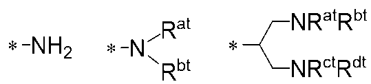
式中、Rat、Rbt、Rct及びRdtは、それぞれ独立して、水素原子又は炭素原子数1~5のアルキル基を表す。ただし、アルキル基中の-CH2-は、酸素原子が直接隣接しないように-O-、-COO-、-C(=O)-、-OCO-で置換されてもよい。
さらに好ましくは、前記化合物(i)における前記吸着基(Kil)は、下記一般式(K-1)~(K-18)のいずれかで表されることが好ましい。

から選ばれる基を表し、WK1は、メチン基又は窒素原子を表すが、メチン基中の水素原子は炭素原子数1~6の直鎖又は分岐のアルキル基で置換されてもよく、
XK1及びYK1はそれぞれ独立して、-CH2-、酸素原子又は硫黄原子を表し、
ZK1は、酸素原子又は硫黄原子を表し、UK1、VK1及びSK1は、それぞれ独立して、メチン基又は窒素原子を表し、TK1は、それぞれ独立して一般式(T-1)~(T-6)
XK1及びYK1はそれぞれ独立して、-CH2-、酸素原子又は硫黄原子を表し、
ZK1は、酸素原子又は硫黄原子を表し、UK1、VK1及びSK1は、それぞれ独立して、メチン基又は窒素原子を表し、TK1は、それぞれ独立して一般式(T-1)~(T-6)

から選ばれる基を表し、ST1は、単結合、炭素原子数1~15個の直鎖状若しくは分岐状のアルキレン基又は炭素原子数2~18個の直鎖状若しくは分岐状のアルケニレン基を表し、当該アルキレン基又は当該アルケニレン基の-CH2-は酸素原子が直接隣接しないように-O-、-COO-、-C(=O)-、-C(=CH2)-又は-OCO-に置換されてもよく、RT1は、炭素原子数1~5のアルキル基を表し、当該アルキル基の-CH2-は酸素原子が直接隣接しないように-O-、-COO-、-C(=O)-、-C(=CH2)-又は-OCO-に置換されてもよく、RT2及びRT3は、それぞれ独立して水素原子又は炭素原子数1~5のアルキル基を表し、一般式(i)で表される化合物は少なくとも一つのPi1-Spi1-基を有し、A、C、D、Z1、Z2、Z3、Z4、Ki1、WK1、XK1、YK1、ZK1、TK1、UK1、VK1、SK1、ST1、RT1、RT2、RT3、Pi1及びSpi1が複数存在する場合、それらは同一であっても異なっていても良い。)
一般式(K-1)~(K-18)で表される部分構造としては、液晶の配向性を重要視する場合は、一般式(K-1)、(K-2)、(K-5)、(K-8)、(K-11)、(K-13)、(K-14)、(K-15)、(K-17)、及び(K-18)が好ましく、信頼性を重要視する場合は(K-1)、(K-9)、(K-11)、(K-13)、及び(K-15)が好ましい。配向性と信頼性の両立を考えた場合に(K-11)、(K-13)及び(K-15)がより好ましい。また(K-13)~(K-18)においてTK1は、一般式(T-1)、(T-3)及び(T-4)で表される基が好ましく、特に(T-1)及び(T-3)がより好ましい。一般式(T-3)中のST1は、単結合、炭素原子数1~10個の直鎖状若しくは分岐状のアルキレン基又は炭素原子数2~10個の直鎖状若しくは分岐状のアルケニレン基を表すことが好ましく、炭素原子数1~7の直鎖状若しくは分岐状のアルキル基又は炭素原子数2~7の直鎖状若しくは分岐状のアルケニレン基が好ましく、炭素原子数1~3の直鎖状アルキル基が好ましく、該アルキル基又はアルキレン基中の-CH2-は酸素原子が直接隣接しないように-O-、-C(=O)-又は-C(=CH2)-で置換されていることが好ましい。一般式(T-3)中のRT1は、直鎖状若しくは分岐状の炭素原子数1~5のアルキル基を表し、当該アルキル基の-CH2-は酸素原子が直接隣接しないように-O-、-C(=O)-、-C(=CH2)-又は-OCO-に置換されていることが好ましく、炭素原子数1~3の直鎖状アルキル基が好ましい。一般式(T-3)中に、少なくとも2個以上の第二級炭素原子は-C(=O)を含むことが好ましい。
一般式(K-1)~(K-18)で表される部分構造としては、液晶の配向性を重要視する場合は、一般式(K-1)、(K-2)、(K-5)、(K-8)、(K-11)、(K-13)、(K-14)、(K-15)、(K-17)、及び(K-18)が好ましく、信頼性を重要視する場合は(K-1)、(K-9)、(K-11)、(K-13)、及び(K-15)が好ましい。配向性と信頼性の両立を考えた場合に(K-11)、(K-13)及び(K-15)がより好ましい。また(K-13)~(K-18)においてTK1は、一般式(T-1)、(T-3)及び(T-4)で表される基が好ましく、特に(T-1)及び(T-3)がより好ましい。一般式(T-3)中のST1は、単結合、炭素原子数1~10個の直鎖状若しくは分岐状のアルキレン基又は炭素原子数2~10個の直鎖状若しくは分岐状のアルケニレン基を表すことが好ましく、炭素原子数1~7の直鎖状若しくは分岐状のアルキル基又は炭素原子数2~7の直鎖状若しくは分岐状のアルケニレン基が好ましく、炭素原子数1~3の直鎖状アルキル基が好ましく、該アルキル基又はアルキレン基中の-CH2-は酸素原子が直接隣接しないように-O-、-C(=O)-又は-C(=CH2)-で置換されていることが好ましい。一般式(T-3)中のRT1は、直鎖状若しくは分岐状の炭素原子数1~5のアルキル基を表し、当該アルキル基の-CH2-は酸素原子が直接隣接しないように-O-、-C(=O)-、-C(=CH2)-又は-OCO-に置換されていることが好ましく、炭素原子数1~3の直鎖状アルキル基が好ましい。一般式(T-3)中に、少なくとも2個以上の第二級炭素原子は-C(=O)を含むことが好ましい。
一般式(T-6)中のRT2及びRT3は、それぞれ独立して水素原子又は炭素原子数1~5のアルキル基を表すが、水素原子を表すことが好ましい。
一般式(K-13)(K-17)の好ましい例としては以下の(K-1-1)~(K-1-4)、(K-3-1)、及び(K-5-1)が、配向性や反応性の点から好ましく、特に好ましくは式(K-1-1)、(K-1-3)、及び(K-3-1)が挙げられる。

(式中、Pi1は重合性基を表し、RT4、RT5及びRT6はそれぞれ独立して水素、炭素原子数1~3のアルキル基を表し、RK1は、水素原子、炭素原子数1~6の直鎖又は分岐のアルキル基を表し該アルキル基中の-CH2-は-CH=CH-、-C≡C-、-O-、-NH-、-OCOO-、-COO-又は-OCO-で置換されてもよいが-O-は連続にはならなく、
nT1及びnT2はそれぞれ独立して0又は1を表し、nT3はそれぞれ独立して0~3の整数を表し、複数存在するRT4、RT5、RT6、nT1、nT2及びnT3は同一であっても異なっていてもよい。)
式(i)中のZ1及びZ2は、好ましくは単結合、-CH=CH-、-CF=CF-、-C≡C-、-COO-、-OCO-、-CF2O-、-OCF2-、-CH=CHCOO-、-OCOCH=CH-、-OCH2CH2O-、又は炭素原子数1~10のアルキレン基、又はこのアルキレン基中の1個又は隣接しない2個以上の-CH2-は-O-、-COO-又は-OCO-で置換された基をそれぞれ表し、より好ましくは、単結合、-COO-、-OCO-、-CH=CHCOO-、-OCOCH=CH-、-OCH2CH2O-、炭素原子数1~6の直鎖状又は分岐状のアルキレン基、又は該アルキレン基中の1個又は隣接しない2個以上の-CH2-が-O-、-COO-又は-OCO-で置換された基で置換された基を表し、Z1及びZ2は更に好ましくは、単結合、-COO-、-OCO-、-OCH2CH2O-、又は炭素原子数2のアルキレン基(エチレン基(-CH2CH2-))若しくはエチレン基中の-CH2-の1個が-O-で置換された基(-CH2O-、-OCH2-)、若しくはエチレン基中の-CH2-の1個が-COO-、-OCO-で置換された基(-CH2-CH2COO-、-OCOCH2-CH2-)である。Z4は、単結合、-O-、-CH=CH-、-COO-、-OCO-、-OCOO-、-CH2-CH(CH3)COO-、-OCOCH(CH3)―CH2-、又は炭素原子数1~20の直鎖又は分岐アルキレン基(該アルキレン基中の1個又は隣接しない2個以上の-CH2-は-O-、-COO-又は-OCO-で置換されてもよい)を表すが、好ましくは、-COO-、-OCO-、-OCH2CH2O-、又は炭素原子数2のアルキレン基(エチレン基(-CH2CH2-))若しくはエチレン基中の-CH2-の1個が-O-で置換された基(-CH2O-、-OCH2-)、若しくは炭素数2~8アルキル基中の-CH2-の1個が-O-、-COO-、-OCO-で置換された基である。
水平配向性の観点から前記吸着基(Ki1)が前記(K-13)~(K-18)から選択され、かつTK1の少なくとも一つは(T-1)であることが好ましい。
具体的部分構造としては、下記の基が挙げられるがこれに限定されるものではない。

式中、Rtcは、水素原子、炭素原子数1~20のアルキル基又はPi1-Spi1-を表す。ただし、アルキル基中の水素原子は、炭素原子数1~12のアルキル基、炭素原子数1~12のハロゲン化アルキル基、炭素原子数1~12のアルコキシ基、炭素原子数1~12のハロゲン化アルコキシ基、ハロゲン原子、シアノ基、ニトロ基、若しくはPi1-Spi1基-、-Z4-Kilで置換されていてもよく、アルキル基中の-CH2-は、酸素原子が直接隣接しないように環式基、-O-、-COO-、-C(=O)-、-OCO-又は-CH=CH-で置換されてもよい。
*は、結合手を表す。
一方で、配向性と溶液安定性のバランスからは、前記吸着基(Ki1)におけるが前記(K-13)~(K-18)から選択され、かつTK1の少なくとも一つは(T-3)であることが好ましい。具体的部分構造としては、下記の基が挙げられるがこれに限定されるものではない。


式中、Rtcは、前記と同様の意味を表す。
また、配向性と電圧保持率のバランスの観点から、前記吸着基(Ki1)が、(K-1)~(K-12)のいずれかであることが好ましい。
化合物(i)は下記一般式(i)で表されることがさらに好ましい。

(式中、Ri1及びRi2は、好ましくはPi1-Spi1基-、水素原子、炭素原子数1~20の直鎖又は分岐のアルキル基、ハロゲン化アルキル基を表し、該アルキル基中の-CH2-は-CH=CH-、-C≡C-、-O-、-COO-、-OCO-又は-OCOO-で置換されてもよいが-O-は連続にはならなく、より好ましくは、Pi1-Spi1基、炭素原子数1~18の直鎖又は分岐のアルキル基、該アルキル基中の-CH2-は、-CH=CH-、-O-、-OCO-で置換(ただし-O-は連続にはならない)され、
A、C及びDはそれぞれ独立して、2価の芳香族基、2価の複素芳香族基、2価の脂肪族基、2価の複素脂肪族基を表し、
Bは、芳香族基を表し、これらAからDの該環構造における任意の水素原子は無置換であるか又は炭素原子数1~12のアルキル基、炭素原子数1~12のハロゲン化アルキル基、炭素原子数1~12のアルコキシ基、炭素原子数1~12のハロゲン化アルコキシ基、ハロゲン原子、シアノ基、ニトロ基、若しくはPi1-Spi1-、-Z4-Kilで置換されていてもよく、
Z1及びZ2はそれぞれ独立して、単結合、-CH=CH-、-CF=CF-、-C≡C-、-COO-、-OCO-、-OCOO-、-CF2O-、-OCF2-、-CH=CHCOO-、-OCOCH=CH-、-CH2-CH2COO-、-OCOCH2―CH2-、-CH=C(CH3)COO-、-OCOC(CH3)=CH-、-CH2-CH(CH3)COO-、-OCOCH(CH3)―CH2-、-OCH2CH2O-、又は炭素原子数2~20のアルキレン基を表し、このアルキレン基中の1個又は隣接しない2個以上の-CH2-は-O-、-COO-又は-OCO-で置換されてもよく、
Z31及びZ32は光異性化又は光二量化反応基であり、それぞれ独立して、下記(Z3-1)~(Z3-5)から選ばれる基、又は単結合を表すが、Z3及び/又はZ32の少なくとも一つは前記(Z3-1)~(Z3-5)のいずれかであり、両端の黒点は結合手を表し、
l、m及びnはそれぞれ独立して、0、1、2の整数を表し、
kは0、1、2の整数を表し、
Z4は、単結合、-O-、-CH=CH-、-COO-、-OCO-、-OCOO-、-CH2-CH(CH3)COO-、-OCOCH(CH3)―CH2-、又は炭素原子数1~20の直鎖又は分岐アルキレン基を表し、該アルキレン基中の1個又は隣接しない2個以上の-CH2-は-O-、-COO-又は-OCO-で置換されてもよく、
Ki1は前記記載と同様に極性基を表し、前記一般式(K-1)~(K-18)のいずれかより選択される基を表す。
式(i)中、Ri1及びRi2は、好ましくはPi1-Spi1-、水素原子、炭素原子数1~20の直鎖又は分岐のアルキル基、ハロゲン化アルキル基を表し、該アルキル基中の-CH2-は-CH=CH-、-C≡C-、-O-、-COO-、-OCO-又は-OCOO-で置換されてもよいが-O-は連続にはならなく、より好ましくは、Pi1-Spi1-、炭素原子数1~18の直鎖又は分岐のアルキル基、該アルキル基中の-CH2-は、-CH=CH-、-O-、-OCO-で置換(ただし-O-は連続にはならない)されても良い。液晶表示素子の信頼性を向上させる観点から、Ri1及びRi2は、Pi1-Spi1-、炭素原子数は2~6のアルキル基が特に好ましい。
一般式(i)で表される化合物は少なくとも一つのPi1-Spi1基を有するが、配向性を向上させる観点から、2つ以上又は3つ以上のPi1-Spi1基を有することが好ましい。一般式(i)において2つ以上又は3つ以上のPi1-Spi1基1が存在する場合、より好ましくはR2が、炭素原子数1~40の直鎖又は分岐のアルキル基、ハロゲン化アルキル基を表し、2つ又は3つ以上のPi1-Spi1基基が一般式(i)中の式(Z3-1)~(Z3-5)から選ばれる基よりもRi1側の位置に存在していることがより好ましい。配向性、信頼性の観点から、さらに好ましくは、Ri1及びRi2の両方ともPi1-Spi1基であり、少なくともひとつのSpi1が単結合であることがさらに好ましい。
一般式(i)中の環Bは、フェニレン基又はナフチレン基が好ましく、1,2,4-フェニレントリイル、1,3,4-フェニレントリイル基がより好ましい。
環A、C及び環Dは、2価の環芳香族基、2価の環複素芳香族基、2価の環脂肪族基、又は2価の環複素脂肪族基、2価の環芳香族基、2価の環複素芳香族基、2価の環脂肪族基、又は2価の環複素脂肪族基が好ましく、具体的には、1,4-フェニレン基、1,4-シクロヘキシレン基、アントラセン-2,6-ジイル基、フェナントレン-2,7-ジイル基、ピリジン-2,5-ジイル基、ピリミジン-2,5-ジイル基、ナフタレン-2,6-ジイル基、インダン-2,5-ジイル基、クロマン-3,7-ジイル、1,2,3,4-テトラヒドロナフタレン-2,6-ジイル基及び1,3-ジオキサン-2,5-ジイル基が好ましく、該環構造は無置換であるか又はL1で置換されていることが好ましい。L1は炭素原子数1~12のアルキル基、炭素原子数1~12のハロゲン化アルキル基、炭素原子数1~12のアルコキシ基、炭素原子数1~12のハロゲン化アルコキシ基、ハロゲン原子、シアノ基、ニトロ基、P-Sp-若しくはZ4-Ki1が好ましく、炭素原子数1~6のアルキル基、炭素原子数1~6のアルコキシ基又はハロゲン原子で置換された基であることがより好ましい。
環A、C及び環Dは、より好ましくは炭素原子数1~12のアルキル基、炭素原子数1~12のハロゲン化アルキル基、炭素原子数1~12のアルコキシ基、ハロゲン原子、若しくはP-Sp-で置換されていてもよく、1,4-フェニレン基、ナフタレン-2,6-ジイル基、ナフタレン-1,4-ジイル基、1,4-シクロへキシレン基又は1,3-ジオキサン-2,5-ジイルである。l、m及びnは、0、1、2の整数を表すが、l+m+n≦1であることが好ましく、l+m+n≦2であることが好ましく、l+m+n≦3がより好ましい。
kは溶液安定性の観点からは、0が好ましく、配向性の観点からは1又は2が好ましい。
Ki1の好ましい様態、およびさらに好ましい様態は前記と同様である。
一般式(i)のより具体的な例としては、下記式(R-1)~(R-57)に表すがこれらに限られたものではない。また、下記式中、置換基の記載は省略している。


(式中、Ri1、Ri2、Z4、Ki1およびkは、それぞれ独立して一般式(i)中のRi1、Ri2、Z4、Ki1およびkとそれぞれ同じ意味を表す。)
液晶組成物用に添加する場合は、本発明の一般式(i)で表される化合物を1種又は2種以上添加してもよく、一般式(i)で表される化合物に加えて、液晶組成物に用いられる公知の重合性化合物、酸化防止剤等を更に含有していてもよい。化合物(i)のより具体的な化合物の例として、下記(P-0-1)から(P-0-30)、および(P-1-1)から(P-1-45)に表す。
液晶組成物用に添加する場合は、本発明の一般式(i)で表される化合物を1種又は2種以上添加してもよく、一般式(i)で表される化合物に加えて、液晶組成物に用いられる公知の重合性化合物、酸化防止剤等を更に含有していてもよい。化合物(i)のより具体的な化合物の例として、下記(P-0-1)から(P-0-30)、および(P-1-1)から(P-1-45)に表す。


(液晶組成物)
本実施形態の液晶組成物は、上記化合物(i)を1種又は2種以上含有する。この液晶組成物は、正または負の誘電率異方性(Δε)を有することが好ましい。なお、液晶組成物に含有される一般式(i)で表される化合物は、式(R-1-1)~(R-1-25)に示される化合物を含めて、上記の化合物(i)と同じであるため、ここでは説明を省略する。
本実施形態の液晶組成物は、上記化合物(i)を1種又は2種以上含有する。この液晶組成物は、正または負の誘電率異方性(Δε)を有することが好ましい。なお、液晶組成物に含有される一般式(i)で表される化合物は、式(R-1-1)~(R-1-25)に示される化合物を含めて、上記の化合物(i)と同じであるため、ここでは説明を省略する。
化合物(i)の含有量は、好ましくは0.01~50質量%であるが、その下限値は、液晶分子を更に好適に配向させられる観点から、液晶組成物全量を基準として、好ましくは、0.01質量%以上、0.1質量%以上、0.5質量%以上、0.7質量%以上、又は1質量%以上である。化合物(i)の含有量の上限値は、応答特性に優れる観点から、液晶組成物全量を基準として、好ましくは、50質量%以下、30質量%以下、10質量%以下であり、7質量%以下、5質量%以下、4質量%以下、又は3質量%以下である。
本発明の組成物は、誘電的に正の異方性を有する液晶組成物を用いることもできるし、誘電的に負の液晶組成物を用いることもできる。
誘電的に正の液晶組成物を用いる場合、該液晶組成物は誘電的に正の化合物(Δεが+2以上)を1種類又は2種類以上含有し、更に誘電的に中性の化合物(Δεが-2より大きく+2より小さい)化合物を1種類又は2種類以上含有することが好ましい。
誘電的に正の化合物は、一般式(2―A)及び/又は一般式(2-B)で表される群から選ばれる化合物であることが好ましい。

(一般式(2-A)及び(2-B)において、R2は炭素数1から7のアルキル、炭素数1から7のアルコキシ、または炭素数2から7のアルケニルであり、環Cは、複数存在する場合は相互に独立して、環上の-CH2基の少なくとも一つがO又はSで置換されていてもよい1,4-シクロへキシレン基、又は、環状の-CH-基の少なくとも一つがNで置換されていてもよい1,4-フェニレン基であり、これら環上のH原子は少なくともひとつのハロゲンで置換されていてもよく、L2は、複数存在する場合は相互に独立して、単結合、-C2H4-、-CH=CH-、-C≡C-、-COO-、-OCO-、-CH2O-、-OCH2-、-CF2O-、OCF2-、であり、X1は、-F、-Cl、-CN、-NCS、-CF3、-OCF3、又は少なくとも1つのHがハロゲン原子で置換された炭素数1~6のアルキル又はアルコキシ基であり、Y1およびY2は相互に独立して、-Hまたは-Fであり、bは、1、2、3、または4である。)
一般式(2-A)及び一般式(2-B)中、R2は炭素原子数1~8のアルキル基、炭素原子数1~8のアルコキシ基、炭素原子数2~8のアルケニル基又は炭素原子数2~8のアルケニルオキシ基が好ましく、炭素原子数1~5のアルキル基、炭素原子数1~5のアルコキシ基、炭素原子数2~5のアルケニル基又は炭素原子数2~5のアルケニルオキシ基が好ましく、炭素原子数1~5のアルキル基又は炭素原子数2~5のアルケニル基が更に好ましく、炭素原子数2~5のアルキル基又は炭素原子数2~3のアルケニル基が更に好ましく、炭素原子数3のアルケニル基(プロペニル基)が特に好ましい。
一般式(2-A)及び一般式(2-B)中、R2は炭素原子数1~8のアルキル基、炭素原子数1~8のアルコキシ基、炭素原子数2~8のアルケニル基又は炭素原子数2~8のアルケニルオキシ基が好ましく、炭素原子数1~5のアルキル基、炭素原子数1~5のアルコキシ基、炭素原子数2~5のアルケニル基又は炭素原子数2~5のアルケニルオキシ基が好ましく、炭素原子数1~5のアルキル基又は炭素原子数2~5のアルケニル基が更に好ましく、炭素原子数2~5のアルキル基又は炭素原子数2~3のアルケニル基が更に好ましく、炭素原子数3のアルケニル基(プロペニル基)が特に好ましい。
信頼性を重視する場合にはR2はアルキル基であることが好ましく、粘性の低下を重視する場合にはアルケニル基であることが好ましい。
また、それが結合する環構造がフェニル基(芳香族)である場合には、直鎖状の炭素原子数1~5のアルキル基、直鎖状の炭素原子数1~4のアルコキシ基及び炭素原子数4~5のアルケニル基が好ましく、それが結合する環構造がシクロヘキサン、ピラン及びジオキサンなどの飽和した環構造の場合には、直鎖状の炭素原子数1~5のアルキル基、直鎖状の炭素原子数1~4のアルコキシ基及び直鎖状の炭素原子数2~5のアルケニル基が好ましい。ネマチック相を安定化させるためには炭素原子及び存在する場合酸素原子の合計が5以下であることが好ましく、直鎖状であることが好ましい。
アルケニル基としては、前記式(R1)から式(R5)のいずれかで表される基から選ばれることが好ましい。
環Cはそれぞれ独立してΔnを大きくすることが求められる場合には芳香族であることが好ましく、応答速度を改善するためには脂肪族であることが好ましく、下記の構造を表すことがより好ましい。

本発明の組成物において、一般式(2-A)及び/又は一般式(2-B)で表される化合物の含有量は、低温での溶解性、転移温度、電気的な信頼性、複屈折率、誘電率異方性などの求められる性能に応じて適宜調整する必要がある。
本発明の組成物の総量に対しての一般式(2-A)及び一般式(2-B)で表される化合物の好ましい含有量の下限値は、1質量%であり、10質量%であり、20質量%であり、30質量%であり、40質量%であり、50質量%であり、55質量%であり、60質量%であり、65質量%であり、70質量%であり、75質量%であり、80質量%である。好ましい含有量の上限値は、本発明の組成物の総量に対して、例えば本発明の一つの形態では95質量%であり、85質量%であり、75質量%であり、65質量%であり、55質量%であり、45質量%であり、35質量%であり、25質量%である。
本発明の組成物の粘度を低く保ち、応答速度が速い組成物が必要な場合は上記の下限値を低めに、上限値を低めにすることが好ましい。さらに、本発明の組成物のTNIを高く保ち、温度安定性の良い組成物が必要な場合は上記の下限値を低めに、上限値を低めにすることが好ましい。また、駆動電圧を低く保つために誘電率異方性を大きくしたいときは、上記の下限値を高めに、上限値を高めにすることが好ましい。
一般式(2-A)で表される化合物としては、一般式(2―A―1)~(2―A―28)で表される化合物が好ましい。


(R2は炭素数1から7のアルキル、炭素数1から7のアルコキシ、または炭素数2から7のアルケニル基を表す。)
一般式(2-B)で表される化合物としては一般式(2-B-1)~(2-B-5)で表される化合物が好ましい。
一般式(2-B)で表される化合物としては一般式(2-B-1)~(2-B-5)で表される化合物が好ましい。

(R2は炭素数1から7のアルキル、炭素数1から7のアルコキシ、または炭素数2から7のアルケニル基を表す。)
一般式(2-A)及び(2-B)で表される化合物は、どちらか一方の群からのみ選択して用いても良いし、それぞれの群から選択して組合わせて用いることもできる。
液晶組成物の信頼性を重視する場合は、一般式(2-A-1)~(2-A-11)、(2-A-16)~(2-A-20)及び一般式(2―B-1)~(2-B-4)で表される群から選択される化合物を用いることが好ましく、中でも一般式(2-A-1)、(2-A-2)、(2-A-4)、(2-A-17)及び(2-A-20)で表される群から選択することがより好ましい。低い粘性を重視する場合は、一般式(2-A-12)~(2-A-15)、(2-A-21)~(2-A-28)及び(2―B-5)~(2-B-6)で表される群から選択される化合物を用いることが好ましく、中でも(2-A-12)、(2-A-13)、(2-A-22)、(2-A-23)及び(2-A-26)で表される群から選択することがより好ましい。低い粘性を重視しつつ、更にFFSモードにおける透過率向上を重視する場合には、(2-A-14)、(2-A-15)、(2-A-25)、(2-A-27)及び(2-A-28)で表される群から選択される化合物を用いることが好ましい。本願発明の液晶表示素子の作製工程におけるUV照射の工程時間を短縮するためには、一般式(2-A-4)~(2-A-7)、(2-A-20)及び(2-B-4)で表される群から選択される化合物を用いることが好ましく、中でも(2-A-4)又は(2-A-20)から選択される化合物が特に好ましく、これらの群の化合物を用いることによりUV照射時の液晶組成物の劣化や液晶表示素子の電圧保持率の低下、焼付きの発生といった不具合を発生させないか、またはその程度を低減することができる。
一般式(2-A-1)~(2-A-28)及び一般式(2―B-1)~(2-B-6)で表される化合物は、液晶表示素子に求める特性に応じて適宜選択し、必要に応じて複数種を組み合わせて用いることができるが、1~12種用いることが好ましく、2~10種用いることがより好ましく、3~8種用いることが特に好ましい。液晶組成物中における各化合物単独での好ましい含有量を以下に示す。なお、表中の数字は質量%を意味する。


誘電的に負の液晶組成物を用いる場合、該液晶組成物は誘電的に負の化合物(Δεが-2以下)を1種類又は2種類以上含有し、更に誘電的に中性の化合物(Δεが-2より大きく+2より小さい)化合物を1種類又は2種類以上含有することが好ましい。
誘電的に負の化合物は、一般式(5)で表される群から選ばれる化合物であることが好ましい。

(R51及びR52は相互に独立して、炭素数1から7のアルキル、炭素数1から7のアルコキシ、炭素数2から7のアルケニル、炭素数2から7のアルケニルオキシであり、環D及びFは相互に独立して、1,4-シクロへキシレン、1,4-シクロへキセニレン、1,4-フェニレン、少なくとも1つの水素がハロゲン原子又はメチル基で置き換えられた1,4-フェニレン、またはテトラヒドロピラン-2,5-ジイルであり、環Eは、2,3-ジフルオロ-1,4-フェニレン、2-クロロ-3-フルオロ-1,4-フェニレン、3,4,5-トリフルオロナフタレン-2,6-ジイル、7,8-ジフルオロクロマン-2,6-ジイル、または、

であり、L4およびL5は相互に独立して、単結合、-C2H4-、-COO-、-OCO-、-CH2O-、-OCH2-、-CF2O、-OCF2-、-CH=CH-、または-C≡Cであり、cは、0、1、2、または3であり、dは0または1であり、cとdの和は3以下である。)
一般式(5)で表される化合物は、Δεが負でその絶対値が3よりも大きな化合物であることが好ましい。
一般式(5)で表される化合物は、Δεが負でその絶対値が3よりも大きな化合物であることが好ましい。
一般式(5)中、R51、R52、はそれぞれ独立して、炭素原子数1~8のアルキル基、炭素原子数1~8のアルコキシ基、炭素原子数2~8のアルケニル基又は炭素原子数2~8のアルケニルオキシ基が好ましく、炭素原子数1~5のアルキル基、炭素原子数1~5のアルコキシ基、炭素原子数2~5のアルケニル基又は炭素原子数2~5のアルケニルオキシ基が好ましく、炭素原子数1~5のアルキル基又は炭素原子数2~5のアルケニル基が更に好ましく、炭素原子数2~5のアルキル基又は炭素原子数2~3のアルケニル基が更に好ましく、炭素原子数3のアルケニル基(プロペニル基)が特に好ましい。
また、それが結合する環構造がフェニル基(芳香族)である場合には、直鎖状の炭素原子数1~5のアルキル基、直鎖状の炭素原子数1~4のアルコキシ基及び炭素原子数4~5のアルケニル基が好ましく、それが結合する環構造がシクロヘキサン、ピラン及びジオキサンなどの飽和した環構造の場合には、直鎖状の炭素原子数1~5のアルキル基、直鎖状の炭素原子数1~4のアルコキシ基及び直鎖状の炭素原子数2~5のアルケニル基が好ましい。ネマチック相を安定化させるためには炭素原子及び存在する場合酸素原子の合計が5以下であることが好ましく、直鎖状であることが好ましい。
アルケニル基としては、前記式(R1)から式(R5)のいずれかで表される基から選ばれることが好ましい。
D及びFはそれぞれ独立してΔnを大きくすることが求められる場合には芳香族であることが好ましく、応答速度を改善するためには脂肪族であることが好ましく、トランス-1,4-シクロへキシレン基、1,4-フェニレン基、2-フルオロ-1,4-フェニレン基、3-フルオロ-1,4-フェニレン基、3,5-ジフルオロ-1,4-フェニレン基、2,3-ジフルオロ-1,4-フェニレン基、1,4-シクロヘキセニレン基、1,4-ビシクロ[2.2.2]オクチレン基、ピペリジン-1,4-ジイル基、ナフタレン-2,6-ジイル基、デカヒドロナフタレン-2,6-ジイル基又は1,2,3,4-テトラヒドロナフタレン-2,6-ジイル基を表すことが好ましく、下記の構造:

を表すことがより好ましく、トランス-1,4-シクロへキシレン基、1,4-シクロヘキセニレン基又は1,4-フェニレン基を表すことがより好ましい。
L4及びL5はそれぞれ独立して-CH2O-、-CF2O-、-CH2CH2-、-CF2CF2-又は単結合を表すことが好ましく、-CH2O-、-CH2CH2-又は単結合が更に好ましく、-CH2O-又は単結合が特に好ましい。
c+dは1、2又は3が好ましく、1又は2がより好ましい。
本実施形態の組成物の総量に対しての式(5)で表される化合物の好ましい含有量の下限値は、1質量%以上であり、10質量%以上であり、20質量%以上であり、30質量%以上であり、40質量%以上であり、50質量%以上であり、55質量%以上であり、60質量%以上であり、65質量%以上であり、70質量%以上であり、75質量%以上であり、80質量%以上である。好ましい含有量の上限値は、95質量%以下であり、85質量%以下であり、75質量%以下であり、65質量%以下であり、55質量%以下であり、45質量%以下であり、35質量%以下であり、25質量%以下であり、20質量%以下である。
本実施形態の組成物の粘度を低く保ち、応答速度が速い組成物が必要な場合は上記の下限値が低く上限値が低いことが好ましい。さらに、本実施形態の組成物のTniを高く保ち、温度安定性の良い組成物が必要な場合は上記の下限値が低く上限値が低いことが好ましい。また、駆動電圧を低く保つために誘電率異方性を大きくしたいときは、上記の下限値を高く上限値が高いことが好ましい。
一般式(5)で表される化合物として、下記の一般式(5-1)~(5-15)で表される化合物群を挙げることができる。


(R51及びR52は一般式(5)における意味と同様の意味を表す。)
液晶組成物の信頼性を重視する場合は、一般式(5-1)、(5-2)、(5-6)、(5-8)~(5-10)、(5-11)~(5-13)で表される群から選択される化合物を用いることが好ましく、中でも一般式(5-1)、(5-6)、(5-9)、(5-10)が特に好ましい。低い粘性を重視する場合は、一般式(5-3)~(5-5)、(5-9)、(5-10)、(5-12)、(5-13)、(5-15)で表される群から選択される化合物を用いることが好ましく、なかでも、(5-3)、(5-4)、(5-9)、(5-10)、(5-13)、(5-15)が特に好ましい。本発明の液晶表示素子の作製工程におけるUV照射の工程時間を短縮するためには、一般式(5-11)~(5-13)で表される群から選択される化合物を用いることが好ましく、中でも(5-13)から選択される化合物が特に好ましく、これらの化合物を用いることによりUV照射時の液晶組成物の劣化や液晶表示素子の電圧保持率の低下、焼付きの発生といった不具合を発生させないか、またはその程度を低減することができる。
液晶組成物の信頼性を重視する場合は、一般式(5-1)、(5-2)、(5-6)、(5-8)~(5-10)、(5-11)~(5-13)で表される群から選択される化合物を用いることが好ましく、中でも一般式(5-1)、(5-6)、(5-9)、(5-10)が特に好ましい。低い粘性を重視する場合は、一般式(5-3)~(5-5)、(5-9)、(5-10)、(5-12)、(5-13)、(5-15)で表される群から選択される化合物を用いることが好ましく、なかでも、(5-3)、(5-4)、(5-9)、(5-10)、(5-13)、(5-15)が特に好ましい。本発明の液晶表示素子の作製工程におけるUV照射の工程時間を短縮するためには、一般式(5-11)~(5-13)で表される群から選択される化合物を用いることが好ましく、中でも(5-13)から選択される化合物が特に好ましく、これらの化合物を用いることによりUV照射時の液晶組成物の劣化や液晶表示素子の電圧保持率の低下、焼付きの発生といった不具合を発生させないか、またはその程度を低減することができる。
一般式(5-1)~(5-15)で表される化合物は、液晶表示素子に求める特性に応じて適宜選択し、必要に応じて複数種を組み合わせて用いることができるが、1~12種用いることが好ましく、2~10種用いることがより好ましく、3~8種用いることが特に好ましい。液晶組成物中における各化合物単独での好ましい含有量を以下に示す。なお、表中の数字は質量%を意味する。

誘電的に正の液晶組成物を用いる場合でも、また、誘電的に負の液晶組成物を用いる場合であっても、誘電的に中性の化合物としては一般式(L)で表される群から選ばれる化合物を用いることが好ましい。
(一般式(L)において、RL1およびRL2は、それぞれ独立して、炭素原子数1~7のアルキル基を表すが、基中に存在する任意の1個または隣接しない2個以上の-CH2-は、それぞれ独立して、-CH=CH-、-C≡C-、-O-、-CO-、-COO-または-OCO-で置換されてもよく、 nL1は、0、1、2または3を表し、AL1、AL2およびAL3は、それぞれ独立して、
(a) 1,4-シクロヘキシレン基(この基中に存在する任意の1個または隣接しない2個以上の-CH2-は、-O-で置換されてもよい。)、
(b) 1,4-フェニレン基(この基中に存在する任意の1個または隣接しない2個以上の-CH=は、-N=で置換されてもよい。)、および
(c) ナフタレン-2,6-ジイル基、1,2,3,4-テトラヒドロナフタレン-2,6-ジイル基またはデカヒドロナフタレン-2,6-ジイル基(これらの基中に存在する任意の1個または隣接しない2個以上の-CH=は、-N=で置換されてもよい。)
からなる群より選ばれる基を表し、前記基(a)、基(b)および基(c)は、それぞれ独立して、シアノ基、フッ素原子または塩素原子で置換されてもよく、ZL1およびZL2は、それぞれ独立して、単結合、-CH2CH2-、-(CH2)4-、-OCH2-、-CH2O-、-COO-、-OCO-、-OCF2-、-CF2O-、-CH=N-N=CH-、-CH=CH-、-CF=CF-または-C≡C-を表し、nL1が2以上の場合は、AL2およびZL2は、それぞれ互いに同一であっても異なっていてもよい。)
一般式(L)で表される化合物は、誘電的にほぼ中性の化合物(Δεの値が-2~2)に該当する。かかる化合物は、1種を単独で用いてもよいが、組み合わせて使用することもできる。組み合わせる化合物の種類は、特に限定されないが、低温での溶解性、転移温度、電気的な信頼性、複屈折率などの所望の性能に応じて適宜選択される。使用する化合物の種類は、例えば、1種類であり、3種類であり、4種類であり、5種類であり、6種類であり、7種類であり、8種類であり、9種類であり、10種類以上である。
液晶組成物中に含まれる一般式(L)で表される化合物の量は、低温での溶解性、転移温度、電気的な信頼性、複屈折率、プロセス適合性、滴下痕、焼き付き、誘電率異方性などの求められる性能に応じて適宜調整される。
その好ましい下限値は、1質量%、10質量%、20質量%、30質量%、40質量%、50質量%、55質量%、60質量%、65質量%、70質量%、75質量%、80質量%である。一方、その好ましい上限値は、95質量%、85質量%、75質量%、65質量%、55質量%、45質量%、35質量%、25質量%である。
液晶組成物の粘度(η)を低く保ち、応答速度を高める場合は、一般式(L)で表される化合物の量は、下限値が高くかつ上限値も高いことが好ましい。さらに、液晶組成物のTniを高く保ち、温度安定性を改善する場合は、その量は下限値が高くかつ上限値も高いことが好ましい。また、液晶表示素子の駆動電圧を低く保つため、液晶組成物のΔεを大きくする場合は、その量は下限値が低くかつ上限値も低いことが好ましい。
信頼性を重視する場合は、RL1およびRL2は、それぞれ独立して、アルキル基が好ましく、化合物の揮発性を低減させることを重視する場合は、RL1およびRL2は、それぞれ独立して、アルコキシ基が好ましく、粘性の低下を重視する場合は、RL1およびRL2のうちの少なくとも一方は、アルケニル基が好ましい。
一般式(L)で表される化合物中に存在するハロゲン原子の数は、0、1、2または3個であることが好ましく、0または1個であることがより好ましい。また、他の液晶分子との相溶性を重視する場合は、ハロゲン原子の数は、1個であることが好ましい。
また、それらが結合する環構造がベンゼン環(芳香族環)である場合は、RL1およびRL2は、それぞれ独立して、直鎖状の炭素原子数1~5のアルキル基、直鎖状の炭素原子数1~4のアルコキシ基、または炭素原子数4~5のアルケニル基が好ましい。
それらが結合する環構造がシクロヘキサン環、ピラン環、ジオキサン環のような飽和した環構造の場合は、RL1およびRL2は、それぞれ独立して、直鎖状の炭素原子数1~5のアルキル基、直鎖状の炭素原子数1~4のアルコキシ基、または直鎖状の炭素原子数2~5のアルケニル基が好ましい。
ネマチック相を安定化させるためには、RL1およびRL2は、それぞれ独立して、炭素原子および酸素原子(存在する場合)の合計が5以下であることが好ましく、直鎖状であることも好ましい。
アルケニル基としては、下記式(R1)~(R5)で表される群から選ばれる基が好ましい。

各式中の黒点は結合手を表す。
nL1は、液晶分子の応答速度を重視する場合は0が好ましく、液晶分子のネマチック相の上限温度を改善する場合は2または3が好ましく、これらのバランスをとる場合は1が好ましい。また、液晶組成物として求められる特性を満たすためには、nL1が異なる値の化合物を組み合わせることが好ましい。
AL1、AL2およびAL3は、それぞれ独立して、液晶分子のΔnを大きくする場合は芳香族基が好ましく、液晶分子の応答速度を改善する場合は脂肪族基が好ましい。
かかる芳香族基または脂肪族基としては、トランス-1,4-シクロへキシレン基、1,4-フェニレン基、2-フルオロ-1,4-フェニレン基、3-フルオロ-1,4-フェニレン基、3,5-ジフルオロ-1,4-フェニレン基、1,4-シクロヘキセニレン基、1,4-ビシクロ[2.2.2]オクチレン基、ピペリジン-1,4-ジイル基、ナフタレン-2,6-ジイル基、デカヒドロナフタレン-2,6-ジイル基、または1,2,3,4-テトラヒドロナフタレン-2,6-ジイル基が好ましく、下記化54で表される構造がより好ましく、トランス-1,4-シクロへキシレン基または1,4-フェニレン基がさらに好ましい。

ZL1およびZL2は、それぞれ独立して、液晶分子の応答速度を重視する場合は単結合が好ましい。
一般式(L)で表される化合物は、下記一般式(L-1)~(L-7)で表される化合物であることが好ましい。
一般式(L-1)で表される化合物は、下記の化合物である。
式中、RL11およびRL12は、それぞれ一般式(L)におけるRL1およびRL2と同じ意味を表す。
RL11およびRL12は、それぞれ独立して、直鎖状の炭素原子数1~5のアルキル基、直鎖状の炭素原子数1~4のアルコキシ基、または直鎖状の炭素原子数2~5のアルケニル基が好ましい。
一般式(L-1)で表される化合物は、1種を単独で使用することもできるが、2種以上を組み合わせて使用することもできる。組み合わせる化合物の種類は、特に限定されないが、低温での溶解性、転移温度、電気的な信頼性、複屈折率などの求められる性能に応じて適宜選択される。使用する化合物の種類は、例えば、1種類であり、2種類であり、3種類であり、4種類であり、5種類以上である。
液晶組成物中に含まれる一般式(L-1)で表される化合物の量は、次の通りであることが好ましい。すなわち、その好ましい下限値は、1質量%、2質量%、3質量%、5質量%、7質量%、10質量%、15質量%、20質量%、25質量%、30質量%、35質量%、40質量%、45質量%、50質量%、55質量%である。一方、その好ましい上限値は、95質量%、90質量%、85質量%、80質量%、75質量%、70質量%、65質量%、60質量%、55質量%、50質量%、45質量%、40質量%、35質量%、30質量%、25質量%である。
液晶組成物の粘度(η)を低く保ち、応答速度を高める場合は、一般式(L-1)で表される化合物の量は、下限値が高くかつ上限値も高いことが好ましい。さらに、液晶組成物のTniを高く保ち、温度安定性を改善する場合は、その量は下限値が中庸かつ上限値も中庸であることが好ましい。また、液晶表示素子の駆動電圧を低く保つため、液晶組成物のΔεを大きくする場合は、その量は下限値が低くかつ上限値も低いことが好ましい。
一般式(L-1)で表される化合物は、下記一般式(L-1-1)で表される化合物であることが好ましい。
式中、RL12は、一般式(L-1)における意味と同じ意味を表す。
一般式(L-1-1)で表される化合物は、下記式(L-1-1.1)~(L-1-1.3)で表される化合物であることが好ましく、式(L-1-1.2)または式(L-1-1.3)で表される化合物であることがより好ましく、式(L-1-1.3)で表される化合物であることが特に好ましい。式(L-1-1.3)で表される化合物を用いると、液晶組成物に低い粘性と高い弾性定数を与えることができ表示素子の高速応答化に有利であるだけでなく、製造工程でのUV照射によるアルケニル化合物特有の劣化が無く、表示品位や信頼性の低下を抑える事ができる点でも好ましい。

液晶組成物中に含まれる式(L-1-1.3)で表される化合物の量は、次の通りであることが好ましい。すなわち、その好ましい下限値は、1質量%、2質量%、3質量%、5質量%、7質量%、10質量%である。一方、その好ましい上限値は、20質量%、15質量%、13質量%、10質量%、8質量%、7質量%、6質量%、5質量%、3質量%である。
一般式(L-1)で表される化合物は、下記一般式(L-1-2)で表される化合物であることが好ましい。
式中、RL12は、一般式(L-1)における意味と同じ意味を表す。
液晶組成物中に含まれる一般式(L-1-2)で表される化合物の量は、次の通りであることが好ましい。すなわち、その好ましい下限値は、1質量%、5質量%、10質量%、である。一方、その好ましい上限値は、60質量%、54質量%、48質量%、42質量%、36質量%、30質量%、24質量%、20質量%、18質量%、15質量%である。
一般式(L-1-2)で表される化合物は、下記式(L-1-2.1)~(L-1-2.4)で表される化合物であることが好ましく、式(L-1-2.2)~(L-1-2.4)で表される化合物であることがより好ましい。特に、式(L-1-2.2)で表される化合物は、液晶組成物の応答速度を改善する効果が高いため好ましく、組成物中における含有量の上限を24重量%以下に抑えることで、製造工程でのUV照射によるアルケニル化合物特有の劣化が抑制され、表示品位や信頼性の低下も抑える事ができる点でも好ましい。
また、液晶組成物の応答速度よりもTniの向上を求める場合は、式(L-1-2.3)または式(L-1-2.4)で表される化合物を用いることが好ましい。液晶組成物中に含まれる式(L-1-2.3)または式(L-1-2.4)で表される化合物の量は、低温での溶解度を高くするために30質量%未満にすることが好ましい。

一般式(L-1)で表される化合物は、下記一般式(L-1-3)で表される化合物であることが好ましい。
式中、RL13およびRL14は、それぞれ独立して、炭素原子数1~8のアルキル基または炭素原子数1~8のアルコキシ基を表す。
RL13およびRL14は、それぞれ独立して、直鎖状の炭素原子数1~5のアルキル基、直鎖状の炭素原子数1~4のアルコキシ基、または直鎖状の炭素原子数2~5のアルケニル基が好ましい。
液晶組成物中に含まれる一般式(L-1-3)で表される化合物の量は、次の通りであることが好ましい。すなわち、その好ましい下限値は、1質量%、5質量%、10質量%、13質量%、15質量%、17質量%、20質量%、23質量%、25質量%、30質量%である。一方、その好ましい上限値は、60質量%、55質量%、50質量%、45質量%、40質量%、37質量%、35質量%、33質量%、30質量%、27質量%、25質量%、23質量%、20質量%、17質量%、15質量%、13質量%、10質量%である。
一般式(L-1-3)で表される化合物は、下記式(L-1-3.1)~(L-1-3.4)または式(L-1-3.11)~(L-1-3.13)で表される化合物であることが好ましく、式(L-1-3.1)、式(L-1-3.3)または式(L-1-3.4)で表される化合物であることがより好ましい。特に、式(L-1-3.1)で表される化合物は、液晶組成物の応答速度を改善する効果が高いため好ましく、誘電的に負の液晶組成物に用いる場合には、式(L-1-1.3)と組合せて用いることでさらに応答速度が速く、UV工程に起因した表示品位や信頼性の低下が抑制された表示素子が得られるのでより好ましい。誘電的に正の液晶組成物に用いる場合、及び/又は24質量%以下の式(L-1-2.2)と組合せて用いることで、さらに応答速度が速く、表示品位や信頼性の低下が抑制された表示素子が得られるので好ましい。
また、液晶組成物の応答速度よりも高いTniの向上を求める場合は、式(L-1-3.3)、式(L-1-3.4)、式(L-1-3.11)または式(L-1-3.12)で表される化合物を用いることが好ましい。液晶組成物中に含まれる式(L-1-3.3)、式(L-1-3.4)、式(L-1-3.11)および式(L-1-3.12)で表される化合物の合計量は、低温での溶解度を高くするために20%未満にすることが好ましい。

一般式(L-1)で表される化合物は、下記一般式(L-1-4)または(L-1-5)で表される化合物であることが好ましい。

式中、RL15およびRL16は、それぞれ独立して、炭素原子数1~8のアルキル基または炭素原子数1~8のアルコキシ基を表す。
RL15およびRL16は、それぞれ独立して、直鎖状の炭素原子数1~5のアルキル基、直鎖状の炭素原子数1~4のアルコキシ基、または直鎖状の炭素原子数2~5のアルケニル基が好ましい。
液晶組成物中に含まれる一般式(L-1-4)で表される化合物の量は、次の通りであることが好ましい。すなわち、その好ましい下限値は、1質量%、5質量%、10質量%、13質量%、15質量%、17質量%、20質量%である。一方、その好ましい上限値は、25質量%、23質量%、20質量%、17質量%、15質量%、13質量%、10質量%である。
液晶組成物中に含まれる一般式(L-1-5)で表される化合物の量は、次の通りであることが好ましい。すなわち、その好ましい下限値は、1質量%、5質量%、10質量%、13質量%、15質量%、17質量%、20質量%である。一方、その好ましい上限値は、25質量%、23質量%、20質量%、17質量%、15質量%、13質量%、10質量%である。
一般式(L-1-4)または(L-1-5)で表される化合物は、下記式(L-1-4.1)~(L-1-4.3)または式(L-1-5.1)~(L-1-5.3)で表される化合物であることが好ましく、式(L-1-4.2)または式(L-1-5.2)で表される化合物であることがより好ましい。

一般式(L-1)で表される化合物は、式(L-1-1.3)、式(L-1-2.2)、式(L-1-3.1)、式(L-1-3.3)、式(L-1-3.4)、式(L-1-3.11)および式(L-1-3.12)で表される化合物から選ばれる2種以上を組み合わせることが好ましく、式(L-1-1.3)、式(L-1-2.2)、式(L-1-3.1)、式(L-1-3.3)、式(L-1-3.4)および式(L-1-4.2)で表される化合物から選ばれる2種以上を組み合わせることがより好ましい。
液晶組成物の信頼性を重視する場合は、式(L-1-3.1)、式(L-1-3.3)および式(L-1-3.4)で表される化合物から選ばれる2種以上を組み合わせることが好ましく、液晶組成物の応答速度を重視する場合は、式(L-1-1.3)および式(L-1-2.2)で表される化合物から選ばれる2種以上を組み合わせることが好ましい。
一般式(L-1)で表される化合物は、下記一般式(L-1-6)で表される化合物であることも好ましい。
式中、RL17およびRL18は、それぞれ独立して、メチル基または水素原子を表す。
液晶組成物中に含まれる一般式(L-1-6)で表される化合物の量は、次の通りであることが好ましい。すなわち、その好ましい下限値は、1質量%、5質量%、10質量%、15質量%、17質量%、20質量%、23質量%、25質量%、27質量%、30質量%、35質量%である。一方、その好ましい上限値は、60質量%、55質量%、50質量%、45質量%、42質量%、40質量%、38質量%、35質量%、33質量%、30質量%である。
一般式(L-1-6)で表される化合物は、下記式(L-1-6.1)~(L-1-6.3)で表される化合物であることが好ましい。

一般式(L-2)で表される化合物は、下記の化合物である。
式中、RL21およびRL22は、それぞれ一般式(L)におけるRL1およびRL2と同じ意味を表す。
RL21は、炭素原子数1~5のアルキル基または炭素原子数2~5のアルケニル基が好ましい。
RL22は、炭素原子数1~5のアルキル基、炭素原子数4~5のアルケニル基または炭素原子数1~4のアルコキシ基が好ましい。
一般式(L-2)で表される化合物は、1種を単独で使用することもできるが、2以上を組み合わせて使用することもできる。組み合わせる化合物の種類は、特に限定されないが、低温での溶解性、転移温度、電気的な信頼性、複屈折率などの求められる性能に応じて適宜選択される。使用する化合物の種類は、例えば、1種類であり、2種類であり、3種類であり、4種類であり、5種類以上である。
液晶組成物中に含まれる一般式(L-2)で表される化合物の量は、次の通りであることが好ましい。すなわち、その好ましい下限値は、1質量%、2質量%、3質量%、5質量%、7質量%、10質量%である。一方、その好ましい上限値は、20質量%、15質量%、13質量%、10質量%、8質量%、7質量%、6質量%、5質量%、3質量%である。
液晶分子の低温での溶解性を重視する場合は、一般式(L-2)で表される化合物の量を多めに設定すると効果が高く、液晶組成物の応答速度を重視する場合は、その量を少なめに設定すると効果が高い。さらに、滴下痕や焼き付き特性を改良する場合は、一般式(L-2)で表される化合物の量を、前記範囲の中間に設定することが好ましい。
一般式(L-2)で表される化合物は、下記式(L-2.1)~(L-2.6)で表される化合物であることが好ましく、式(L-2.1)、式(L-2.3)、式(L-2.4)または式(L-2.6)で表される化合物であることがより好ましい。
一般式(L-2)で表される化合物は、下記式(L-2.1)~(L-2.6)で表される化合物であることが好ましく、式(L-2.1)、式(L-2.3)、式(L-2.4)または式(L-2.6)で表される化合物であることがより好ましい。

一般式(L-3)で表される化合物は、下記の化合物である。
式中、RL31およびRL32は、それぞれ一般式(L)におけるRL1およびRL2と同じ意味を表す。
RL31およびRL32は、それぞれ独立して、炭素原子数1~5のアルキル基、炭素原子数4~5のアルケニル基、または炭素原子数1~4のアルコキシ基が好ましい。
一般式(L-3)で表される化合物は、1種を単独で使用することもできるが、2種以上を組み合わせて使用することもできる。組み合わせる化合物の種類は、特に限定されないが、低温での溶解性、転移温度、電気的な信頼性、複屈折率などの求められる性能に応じて適宜選択される。使用する化合物の種類は、例えば、1種類であり、2種類であり、3種類であり、4種類であり、5種類以上である。
液晶組成物中に含まれる一般式(L-3)で表される化合物の量は、次の通りであることが好ましい。すなわち、その好ましい下限値は、1質量%、2質量%、3質量%、5質量%、7質量%、10質量%である。一方、その好ましい上限値は、20質量%、15質量%、13質量%、10質量%、8質量%、7質量%、6質量%、5質量%、3質量%である。
なお、高い複屈折率を得る場合は、一般式(L-3)で表される化合物の量を多めに設定すると効果が高く、高いTniを重視する場合は、その量を少なめに設定すると効果が高い。さらに、滴下痕や焼き付き特性を改良する場合は、一般式(L-3)で表される化合物の量を、前記範囲の中間に設定することが好ましい。
一般式(L-3)で表される化合物は、下記式(L-3.1)~(L-3.4)、式(L-3.6)または式(L-3.7)で表される化合物であることが好ましく、式(L-3.2)~(L-3.4)、式(L-3.6)または式(L-3.7)で表される化合物であることが好ましい。

一般式(L-4)で表される化合物は、下記の化合物である。
式中、RL41およびRL42は、それぞれ一般式(L)におけるRL1およびRL2と同じ意味を表す。
RL41は、炭素原子数1~5のアルキル基または炭素原子数2~5のアルケニル基が好ましい。
RL42は、炭素原子数1~5のアルキル基、炭素原子数4~5のアルケニル基または炭素原子数1~4のアルコキシ基が好ましい。
一般式(L-4)で表される化合物は、1種を単独で使用することもできるが、2種以上を組み合わせて使用することもできる。組み合わせる化合物の種類は、特に限定されないが、低温での溶解性、転移温度、電気的な信頼性、複屈折率などの求められる性能に応じて適宜選択される。使用する化合物の種類は、例えば、1種類であり、2種類であり、3種類であり、4種類であり、5種類以上である。
液晶組成物中に含まれる一般式(L-4)で表される化合物の量は、低温での溶解性、転移温度、電気的な信頼性、複屈折率、プロセス適合性、滴下痕、焼き付き、誘電率異方性などの求められる性能に応じて適宜調整される。
その好ましい下限値は、1質量%、2質量%、3質量%、5質量%、7質量%、10質量%、14質量%、16質量%、20質量%、23質量%、26質量%、30質量%、35質量%、40質量%である。一方、その好ましい上限値は、50質量%、40質量%、35質量%、30質量%、20質量%、15質量%、10質量%、5質量%である。
一般式(L-4)で表される化合物は、下記式(L-4.1)~(L-4.3)で表される化合物であることが好ましい。

低温での溶解性、転移温度、電気的な信頼性、複屈折率などの求められる性能に応じて、液晶組成物は、式(L-4.1)で表される化合物のみを含んでも、式(L-4.2)で表される化合物のみを含んでも、式(L-4.1)で表される化合物および式(L-4.2)で表される化合物の双方を含んでもよく、式(L-4.1)~(L-4.3)で表される化合物の全てを含んでもよい。
一般式(L-4)で表される化合物は、下記式(L-4.4)~(L-4.6)で表される化合物であることも好ましく、式(L-4.4)で表される化合物であることがより好ましい。

低温での溶解性、転移温度、電気的な信頼性、複屈折率などの求められる性能に応じて、液晶組成物は、式(L-4.4)で表される化合物のみを含んでも、式(L-4.5)で表される化合物のみを含んでもよく、式(L-4.4)で表される化合物および式(L-4.5)で表される化合物の双方を含んでもよい。
一般式(L-4)で表される化合物は、下記式(L-4.7)~(L-4.10)で表される化合物であることも好ましく、式(L-4.9)で表される化合物がより好ましい。

一般式(L-5)で表される化合物は、下記の化合物である。
式中、RL51およびRL52は、それぞれ一般式(L)におけるRL1およびRL2と同じ意味を表す。
RL51は、炭素原子数1~5のアルキル基または炭素原子数2~5のアルケニル基が好ましい。
RL52は、炭素原子数1~5のアルキル基、炭素原子数4~5のアルケニル基、または炭素原子数1~4のアルコキシ基が好ましい。
一般式(L-5)で表される化合物は、1種を単独で使用することもできるが、2種以上を組み合わせて使用することもできる。組み合わせる化合物の種類は、特に限定されないが、低温での溶解性、転移温度、電気的な信頼性、複屈折率などの求められる性能に応じて適宜選択される。使用する化合物の種類は、例えば、1種類であり、2種類であり、3種類であり、4種類であり、5種類以上である。
液晶組成物中に含まれる一般式(L-5)で表される化合物の量は、低温での溶解性、転移温度、電気的な信頼性、複屈折率、プロセス適合性、滴下痕、焼き付き、誘電率異方性などの求められる性能に応じて適宜調整される。
その好ましい下限値は、1質量%、2質量%、3質量%、5質量%、7質量%、10質量%、14質量%、16質量%、20質量%、23質量%、26質量%、30質量%、35質量%、40質量%である。一方、その好ましい上限値は、50質量%、40質量%、35質量%、30質量%、20質量%、15質量%、10質量%、5質量%である。
一般式(L-5)で表される化合物は、下記式(L-5.1)または式(L-5.2)で表される化合物であることが好ましく、式(L-5.1)で表される化合物であることがより好ましい。

一般式(L-5)で表される化合物は、下記式(L-5.3)または式(L-5.4)で表される化合物であることも好ましい。

一般式(L-5)で表される化合物は、下記式(L-5.5)~(L-5.7)で表される化合物であることも好ましく、式(L-5.7)で表される化合物であることがより好ましい。

一般式(L-6)で表される化合物は、下記の化合物である。

式中、RL61およびRL62は、それぞれ一般式(L)におけるRL1およびRL2と同じ意味を表し、XL61およびXL62は、水素原子であるか又はいずれか一方がフッ素原子を表す。
RL61およびRL62は、それぞれ独立して、炭素原子数1~5のアルキル基または炭素原子数2~5のアルケニル基が好ましいく、XL61およびXL62のうちの一方がフッ素原子、他方が水素原子であることが好ましく、XL62がフッ素原子でいあることがより好ましい。
RL61およびRL62は、それぞれ独立して、炭素原子数1~5のアルキル基または炭素原子数2~5のアルケニル基が好ましいく、XL61およびXL62のうちの一方がフッ素原子、他方が水素原子であることが好ましく、XL62がフッ素原子でいあることがより好ましい。
一般式(L-6)で表される化合物は、1種を単独で使用することもできるが、2種以上を組み合わせて使用することもできる。組み合わせる化合物の種類は、特に限定されないが、低温での溶解性、転移温度、電気的な信頼性、複屈折率などの求められる性能に応じて適宜選択される。使用する化合物の種類は、例えば、1種類であり、2種類であり、3種類であり、4種類であり、5種類以上である。また、一般式(L-6)で表される群から化合物は、本願発明の液晶表示素子の作製工程におけるUV照射の工程時間を短縮するためにも好ましい。これによりUV照射時の液晶組成物の劣化や液晶表示素子の電圧保持率の低下、焼付きの発生といった不具合を発生させないか、またはその程度を低減することができる。
液晶組成物中に含まれる一般式(L-6)で表される化合物の量は、次の通りであることが好ましい。すなわち、その好ましい下限値は、1質量%、2質量%、3質量%、5質量%、7質量%、10質量%、14質量%、16質量%、20質量%、23質量%、26質量%、30質量%、35質量%、40質量%である。一方、その好ましい上限値は、50質量%、40質量%、35質量%、30質量%、20質量%、15質量%、10質量%、5質量%である。
なお、Δnを大きくすることに重点を置く場合は、一般式(L-6)で表される化合物の量を多くした方が好ましく、低温での析出に重点を置いた場合は、その量を少なくした方が好ましい。
一般式(L-6)で表される化合物は、下記式(L-6.1)~(L-6.9)で表される化合物であることが好ましい。

組み合わせる化合物の種類は、特に限定されないが、1種~3種を用いることが好ましく、1種~4種を用いることがより好ましい。また、選択する化合物の分子量分布が広いことも溶解性に有効であるため、例えば、式(L-6.1)および式(L-6.2)で表される化合物から1種と、式(L-6.4)および式(L-6.5)で表される化合物から1種と、式(L-6.6)および式(L-6.7)で表される化合物から1種と、式(L-6.8)および式(L-6.9)で表される化合物から1種とを選択し、これらを適宜組み合わせることが好ましい。中でも、式(L-6.1)、式(L-6.3)、式(L-6.4)、式(L-6.6)および式(L-6.9)で表される化合物の組み合わせがより好ましい。
一般式(L-6)で表される化合物は、下記式(L-6.10)~(L-6.17)で表される化合物であることも好ましく、式(L-6.11)で表される化合物であることがより好ましい。

一般式(L-7)で表される化合物は、下記の化合物である。

式中、RL71およびRL72は、それぞれ一般式(L)におけるRL1およびRL2と同じ意味を表す。
AL71およびAL72は、それぞれ一般式(L)におけるAL2およびAL3と同じ意味を表す。ただし、AL71およびAL72中に存在する任意の水素原子は、フッ素原子で置換されてもよい。
ZL71は、一般式(L)におけるZL2と同じ意味を表す。
XL71およびXL72は、それぞれ独立して、フッ素原子または水素原子を表す。
式中、RL71およびRL72は、それぞれ独立して、炭素原子数1~5のアルキル基、炭素原子数2~5のアルケニル基、または炭素原子数1~4のアルコキシ基が好ましい。
AL71およびAL72は、それぞれ独立して、1,4-シクロヘキシレン基または1,4-フェニレン基が好ましい。ただし、AL71およびAL72中に存在する任意の水素原子は、フッ素原子で置換されてもよい。
ZL71は、単結合またはCOO-が好ましく、単結合がより好ましい。
XL71およびXL72は、それぞれ水素原子が好ましい。
組み合わせる化合物の種類は、特に限定されないが、低温での溶解性、転移温度、電気的な信頼性、複屈折率などの求められる性能に応じて適宜選択される。使用する化合物の種類は、例えば、1種類であり、2種類であり、3種類であり、4種類である。
液晶組成物中に含まれる一般式(L-7)で表される化合物の量は、低温での溶解性、転移温度、電気的な信頼性、複屈折率、プロセス適合性、滴下痕、焼き付き、誘電率異方性などの求められる性能に応じて適宜調整される。
その好ましい下限値は、1質量%、2質量%、3質量%、5質量%、7質量%、10質量%、14質量%、16質量%、20質量%である。一方、その好ましい上限値は、30質量%、25質量%、23質量%、20質量%、18質量%、15質量%、10質量%、5質量%である。
液晶組成物の高いTniが要求される場合は、一般式(L-7)で表される化合物の量を多めにすることが好ましく、低粘度であることが望まれる場合は、その量を少なめにすることが好ましい。
一般式(L-7)で表される化合物は、下記式(L-7.1)~(L-7.4)で表される化合物であることが好ましく、式(L-7.2)で表される化合物であることがより好ましい。

一般式(L-7)で表される化合物は、下記式(L-7.11)~(L-7.13)で表される化合物であることも好ましく、式(L-7.11)で表される化合物であることがより好ましい。

一般式(L-7)で表される化合物は、下記式(L-7.21)~(L-7.23)で表される化合物であることも好ましく、式(L-7.21)で表される化合物であることがより好ましい。

一般式(L-7)で表される化合物は、下記式(L-7.31)~(L-7.34)で表される化合物であることも好ましく、式(L-7.31)または式(L-7.32)で表される化合物であることがより好ましい。

また、一般式(L-7)で表される化合物は、下記式(L-7.41)~(L-7.44)で表される化合物であることも好ましく、式(L-7.41)または式(L-7.42)で表される化合物であることがより好ましい。

さらに、一般式(L-7)で表される化合物は、下記式(L-7.51)~(L-7.53)で表される化合物であることも好ましい。

誘電的に正の液晶組成物を用いる場合、該液晶組成物は誘電的に正の化合物(Δεが+2以上)を1種類又は2種類以上含有する以外に、誘電的に負(Δεが-2より大きく+2より小さい)の化合物を1種類又は2種類以上含有することができる。この場合も、誘電的に正の化合物は一般式(2-A)及び一般式(2-B)で表される群から選択される化合物を用いることが好ましく、誘電的に負の化合物は一般式(5)で表される化合物を用いることが好ましい。更に、一般式(L)で表される誘電的に中性の化合物を少なくとも1種類含有する事がより好ましい。誘電的に正と負の化合物を組合わせると、液晶組成物の平均誘電率を増大させることができる。これにより、横電界成分で駆動する液晶モードにおいて高い透過率を備えた液晶表示素子を得られる点で好ましく、FFSや、電極幅や電極間距離の狭いIPSなどのフリンジ電場が発生しやすいモードに特に好適に用いることができる。誘電的に正と負の化合物を同時に用いる場合も、組成部全体における各化合物の好ましい含有量は、前記記載に従って適宜決定することができる。
また本発明の液晶組成物は、一般式(i)で表される化合物とは異なる他の重合性化合物を更に含有してもよい。重合性化合物は、液晶組成物に用いられる公知の重合性化合物であってよい。重合性化合物の例としては、一般式(P):

(上記一般式(P)中、Rp1は、水素原子、フッ素原子、シアノ基、炭素原子数1~15のアルキル基又は-Spp2-Pp2を表し、該アルキル基中の1個又は非隣接の2個以上の-CH2-はそれぞれ独立して-CH=CH-、-C≡C-、-O-、-CO-、-COO-又は-OCO-によって置換されていてもよく、該アルキル基中の1個又は2個以上の水素原子はそれぞれ独立して、シアノ基、フッ素原子又は塩素原子で置換されていても良く、
Pp1及びPp2はそれぞれ独立して、一般式(Pp1-1)~式(Pp1-9)
Pp1及びPp2はそれぞれ独立して、一般式(Pp1-1)~式(Pp1-9)

(式中、Rp11及びRp12はそれぞれ独立して、水素原子、炭素原子数1~5のアルキル基又は炭素原子数1~5のハロゲン化アルキル基を表し、Wp11は単結合、-O-、-COO-又はメチレン基を表し、tp11は、0、1又は2を表すが、分子内にRp11、Rp12、Wp11及び/又はtp11が複数存在する場合、それらは同一であっても異なっていても良い。)
のいずれかを表し、
Spp1及びSpp2はそれぞれ独立して、単結合又はスペーサー基を表し、
Zp1及びZp2はそれぞれ独立して、単結合、-O-、-S-、-CH2-、-OCH2-、-CH2O-、-CO-、-C2H4-、-COO-、-OCO-、-OCOOCH2-、-CH2OCOO-、-OCH2CH2O-、-CO-NRZP1-、-NRZP1-CO-、-SCH2-、-CH2S-、-CH=CRZP1-COO-、-CH=CRZP1-OCO-、-COO-CRZP1=CH-、-OCO-CRZP1=CH-、-COO-CRZP1=CH-COO-、-COO-CRZP1=CH-OCO-、-OCO-CRZP1=CH-COO-、-OCO-CRZP1=CH-OCO-、-(CH2)z-COO-、-(CH2)2-OCO-、-OCO-(CH2)2-、-(C=O)-O-(CH2)2-、-CH=CH-、-CF=CF-、-CF=CH-、-CH=CF-、-CF2-、-CF2O-、-OCF2-、-CF2CH2-、-CH2CF2-、-CF2CF2-又は-C≡C-(式中、RZP1はそれぞれ独立して水素原子又は炭素原子数1~4のアルキル基を表すが、分子内にRZP1が複数存在する場合、それらは同一であっても異なっていても良い。)
を表し、
Ap1、Ap2及びAp3はそれぞれ独立して、
(ap) 1,4-シクロヘキシレン基(この基中に存在する1個の-CH2-又は隣接していない2個以上の-CH2-は-O-に置き換えられてもよい。)
(bp) 1,4-フェニレン基(この基中に存在する1個の-CH=又は隣接していない2個以上の-CH=は-N=に置き換えられてもよい。)及び
(cp) ナフタレン-2,6-ジイル基、ナフタレン-1,4-ジイル基、1,2,3,4-テトラヒドロナフタレン-2,6-ジイル基、デカヒドロナフタレン-2,6-ジイル基、フェナントレン-2,7-ジイル基又はアントラセン-2,6-ジイル基(これら基中に存在する1個の-CH=又は隣接していない2個以上の-CH=は-N=に置き換えられても良く、この基中に存在する水素原子は、ハロゲン原子、炭素原子数1~8のアルキル基又は炭素原子数1~8のアルケニル基で置換されていてもよい。)
からなる群より選ばれる基を表し、上記の基(ap)、基(bp)及び基(cp)は、それぞれ独立して、この基中に存在する水素原子は、ハロゲン原子、炭素原子数1~8のアルキル基又は炭素原子数1~8のアルケニル基で置換されていてもよく、シアノ基、フッ素原子、塩素原子又は-Spp2-Pp2で置換されていても良く、
mp1は、0、1、2又は3を表し、分子内にZp1、Ap2、Spp2及び/又はPp2が複数存在する場合、それらは同一であっても異なっていても良いが、Ap3は、mp1が0で、Ap1がフェナントレン-2,7-ジイル基又はアントラセン-2,6-ジイル基である場合には単結合を表す。ただし、化合物(i)のkが0の場合,一般式(i)で表される化合物(i)を除く。)
で表される化合物が好ましい。また、当該重合性化合物は1種又は2種以上含有することが好ましい。
本発明に係る一般式(P)において、Rp1は-Spp2-Pp2であることが好ましい。
Pp1及びPp2はそれぞれ独立して式(Pp1-1)~式(Pp1-3)のいずれかであることが好ましく、(Pp1-1)であることが好ましい。
Rp11及びRp12はそれぞれ独立して、水素原子又はメチル基であることが好ましい。
tp11は、0又は1が好ましい。
Wp11は、単結合、メチレン基又はエチレン基が好ましい。
mp1は0、1又は2であることが好ましく、0又は1が好ましい。
Zp1及びZp2はそれぞれ独立して、単結合、-OCH2-、-CH2O-、-CO-、-C2H4-、-COO-、-OCO-、-COOC2H4-、-OCOC2H4-、-C2H4OCO-、-C2H4COO-、-CH=CH-、-CF2-、-CF2O-、-(CH2)2-COO-、-(CH2)2-OCO-、-OCO-(CH2)2-、-CH=CH-COO-、-COO-CH=CH-、-OCOCH=CH-、-COO-(CH2)2-、-OCF2-又は-C≡C-が好ましく、単結合、-OCH2-、-CH2O-、-C2H4-、-COO-、-OCO-、-COOC2H4-、-OCOC2H4-、-C2H4OCO-、-C2H4COO-、-CH=CH-、-(CH2)2-COO-、-(CH2)2-OCO-、-OCO-(CH2)2-、-CH=CH-COO-、-COO-CH=CH-、-OCOCH=CH-、-COO-(CH2)2-又は-C≡C-が好ましく、分子内に存在する1つのみが-OCH2-、-CH2O-、-C2H4-、-COO-、-OCO-、-COOC2H4-、-OCOC2H4-、-C2H4OCO-、-C2H4COO-、-CH=CH-、-(CH2)2-COO-、-(CH2)2-OCO-、-OCO-(CH2)2-、-CH=CH-COO-、-COO-CH=CH-、-OCOCH=CH-、-COO-(CH2)2-又は-C≡C-であり、他がすべて単結合であることが好ましく、分子内に存在する1つのみが、-OCH2-、-CH2O-、-C2H4-、-COO-又は-OCO-であり、他がすべて単結合であることが好ましく、すべてが単結合であることが好ましい。
また、分子内に存在するZp1及びZp2の1つのみが、-CH=CH-COO-、-COO-CH=CH-、-(CH2)2-COO-、-(CH2)2-OCO-、-O-CO-(CH2)2-、-COO-(CH2)2-からなる群から選択される連結基であり、他は単結合であることが好ましい。
Spp1及びSpp2はそれぞれ独立して、単結合又はスペーサー基を表すが、スペーサー基は、炭素原子数1~30のアルキレン基が好ましく、該アルキレン基中の-CH2-は酸素原子同士が直接連結しない限りにおいて-O-、-CO-、-COO-、-OCO-、-CH=CH-又は-C≡C-で置換されていてもよく、該アルキレン基中の水素原子はハロゲン原子で置換されていても良いが、直鎖の炭素原子数1~10のアルキレン基又は単結合が好ましい。
Ap1、Ap2及びAp3はそれぞれ独立して、1,4-フェニレン基又は1,4-シクロヘキシレン基が好ましく、1,4-フェニレン基が好ましい。1,4-フェニレン基は液晶化合物との相溶性を改善するために、1個のフッ素原子、1個のメチル基又は1個のメトキシ基で置換されていることが好ましい。
一般式(P)で表される化合物の合計の含有量は、本願の一般式(P)で表される化合物を含む組成物に対して、0.05~10%含んでいることが好ましく、0.1~8%含んでいることが好ましく、0.1~5%含んでいることが好ましく、0.1~3%含んでいることが好ましく、0.2~2%含んでいることが好ましく、0.2~1.3%含んでいることが好ましく、0.2~1%含んでいることが好ましく、0.2~0.56%含んでいることが好ましい。
一般式(P)で表される化合物の合計の含有量の好ましい下限値は、本願の一般式(P)で表される化合物を含む組成物に対して、0.01%であり、0.03%であり、0.05%であり、0.08%であり、0.1%であり、0.15%であり、0.2%であり、0.25%であり、0.3%である。
一般式(P)で表される化合物の合計の含有量の好ましい上限値は、本願の一般式(P)で表される化合物を含む組成物に対して、10%であり、8%であり、5%であり、3%であり、1.5%であり、1.2%であり、1%であり、0.8%であり、0.5%である。
含有量が少ないと一般式(P)で表される化合物を加える効果が現れにくく、液晶組成物の配向規制力が弱い又は経時的に弱くなってしまうなどの問題が発生し、多すぎると硬化後に残存する量が多くなる、硬化に時間がかかる、液晶の信頼性が低下する等の問題が生じる。このため、これらのバランスを考慮し含有量を設定する。
一般式(i)で表される化合物及び一般式(P)で表される化合物の合計の含有量は、それら化合物を含む組成物に対して、0.05~10%含んでいることが好ましく、0.1~8%含んでいることが好ましく、0.1~5%含んでいることが好ましく、0.1~3%含んでいることが好ましく、0.2~2%含んでいることが好ましく、0.2~1.3%含んでいることが好ましく、0.2~1%含んでいることが好ましく、0.2~0.56%含んでいることが好ましい。
一般式(i)で表される化合物及び一般式(P)で表される化合物の合計の含有量の好ましい下限値は、それら化合物を含む組成物に対して、0.01%であり、0.03%であり、0.05%であり、0.08%であり、0.1%であり、0.15%であり、0.2%であり、0.25%であり、0.3%である。
一般式(i)で表される化合物及び一般式(P)で表される化合物の合計の含有量の好ましい上限値は、それら化合物を含む組成物に対して、10%であり、8%であり、5%であり、3%であり、1.5%であり、1.2%であり、1%であり、0.8%であり、0.5%である。
含有量が少ないと一般式(i)で表される化合物及び一般式(P)で表される化合物を加える効果が現れにくく、液晶組成物の配向規制力が弱い又は経時的に弱くなってしまうなどの問題が発生し、多すぎると硬化後に残存する量が多くなる、硬化に時間がかかる、液晶の信頼性が低下する等の問題が生じる。このため、これらのバランスを考慮し含有量を設定する。
本発明に係る一般式(P)で表される化合物の好ましい例として、下記式(P-1-1)~式(P-1-46)で表される重合性化合物が挙げられる。


(式中、Pp11、Pp12、Spp11及びSpp12は、一般式(P-1)におけるPp11、Pp12、Spp11及びSpp12と同じ意味を表す。)
本発明に係る一般式(P)で表される化合物の好ましい例として、下記式(P-2-1)~式(P-2-12)で表される重合性化合物が挙げられる。
本発明に係る一般式(P)で表される化合物の好ましい例として、下記式(P-2-1)~式(P-2-12)で表される重合性化合物が挙げられる。

(式中、Pp21、Pp22、Spp21及びSpp22は、一般式(P-2)におけるPp21、Pp22、Spp21及びSpp22と同じ意味を表す。)
本発明に係る一般式(P)で表される化合物の好ましい例として、下記式(P-3-1)~式(P-3-15)で表される重合性化合物が挙げられる。
本発明に係る一般式(P)で表される化合物の好ましい例として、下記式(P-3-1)~式(P-3-15)で表される重合性化合物が挙げられる。


(式中、Pp31、Pp32、Spp31及びSpp32は、一般式(P-3)におけるPp31、Pp32、Spp31及びSpp32と同じ意味を表す。)
本発明に係る一般式(P)で表される化合物の好ましい例として、下記式(P-4-1)~式(P-4-15)で表される重合性化合物が挙げられる。
本発明に係る一般式(P)で表される化合物の好ましい例として、下記式(P-4-1)~式(P-4-15)で表される重合性化合物が挙げられる。


(式中、Pp41、Pp42、Spp41及びSpp42は、一般式(P-4)におけるPp41、Pp42、Spp41及びSpp42と同じ意味を表す。)
本発明における組成物は、さらに、信頼性を向上させるため添加剤として化合物(Q)を1種又は2種以上含有することができる。化合物(Q)は下記の構造を有することが好ましい。
本発明における組成物は、さらに、信頼性を向上させるため添加剤として化合物(Q)を1種又は2種以上含有することができる。化合物(Q)は下記の構造を有することが好ましい。

(式中、RQは水酸基、水素原子、炭素原子数1から22の直鎖アルキル基又は分岐鎖アルキル基を表し、該アルキル基中の1つ又は2つ以上のCH2基は、酸素原子が直接隣接しないように、-O-、-CH=CH-、-CO-、-OCO-、-COO-、-C≡C-、-CF2O-、-OCF2-で置換されてよく、*で他の構造と結合する。)
RQは炭素原子数1から22の直鎖アルキル基又は分岐鎖アルキル基を表し、該アルキル基中の1つ又は2つ以上のCH2基は、酸素原子が直接隣接しないように、-O-、-CH=CH-、-CO-、-OCO-、-COO-、-C≡C-、-CF2O-、-OCF2-で置換されてよいが、炭素原子数1から10の直鎖アルキル基、直鎖アルコキシ基、1つのCH2基が-OCO-又は-COO-に置換された直鎖アルキル基、分岐鎖アルキル基、分岐アルコキシ基、1つのCH2基が-OCO-又は-COO-に置換された分岐鎖アルキル基が好ましく、炭素原子数1から20の直鎖アルキル基、1つのCH2基が-OCO-又は-COO-に置換された直鎖アルキル基、分岐鎖アルキル基、分岐アルコキシ基、1つのCH2基が-OCO-又は-COO-に置換された分岐鎖アルキル基が更に好ましい。MQはトランス-1,4-シクロへキシレン基、1,4-フェニレン基又は単結合を表すが、トランス-1,4-シクロへキシレン基又は1,4-フェニレン基が好ましい。
RQは炭素原子数1から22の直鎖アルキル基又は分岐鎖アルキル基を表し、該アルキル基中の1つ又は2つ以上のCH2基は、酸素原子が直接隣接しないように、-O-、-CH=CH-、-CO-、-OCO-、-COO-、-C≡C-、-CF2O-、-OCF2-で置換されてよいが、炭素原子数1から10の直鎖アルキル基、直鎖アルコキシ基、1つのCH2基が-OCO-又は-COO-に置換された直鎖アルキル基、分岐鎖アルキル基、分岐アルコキシ基、1つのCH2基が-OCO-又は-COO-に置換された分岐鎖アルキル基が好ましく、炭素原子数1から20の直鎖アルキル基、1つのCH2基が-OCO-又は-COO-に置換された直鎖アルキル基、分岐鎖アルキル基、分岐アルコキシ基、1つのCH2基が-OCO-又は-COO-に置換された分岐鎖アルキル基が更に好ましい。MQはトランス-1,4-シクロへキシレン基、1,4-フェニレン基又は単結合を表すが、トランス-1,4-シクロへキシレン基又は1,4-フェニレン基が好ましい。
化合物(Q)は、より具体的には、下記の一般式(Q-a)から一般式(Q-d)で表される化合物が好ましい。

式中、RQ1は炭素原子数1から10の直鎖アルキル基又は分岐鎖アルキル基が好ましく、RQ2は炭素原子数1から20の直鎖アルキル基又は分岐鎖アルキル基が好ましく、RQ3は炭素原子数1から8の直鎖アルキル基、分岐鎖アルキル基、直鎖アルコキシ基又は分岐鎖アルコキシ基が好ましく、LQは炭素原子数1から8の直鎖アルキレン基又は分岐鎖アルキレン基が好ましい。一般式(Q-a)から一般式(Q-d)で表される化合物中、一般式(Q-c)及び一般式(Q-d)で表される化合物が更に好ましい。
本願発明の組成物において、一般式(Q)で表される化合物を1種又は2種を含有することが好ましく、1種から5種含有することが更に好ましく、その含有量は0.001から1%であることが好ましく、0.001から0.1%が更に好ましく、0.001から0.05%が特に好ましい。
また、本発明に使用できる酸化防止剤又は光安定剤としてより具体的には以下の(Q-1)~(Q-44)で表される化合物が好ましい。


(式中、nは0から20の整数を表す。)
本発明における液晶組成物の熱安定性を高めるため、酸化防止剤を添加することがとくに好ましい。より具体的な酸化防止剤としては、ヒドロキノン誘導体、ニトロソアミン系重合禁止剤、ヒンダードフェノール系酸化防止剤等が挙げられ、より具体的には、tert-ブチルハイドロキノン、メチルハイドロキノン、和光純薬工業株式会社製の「Q-1300」、「Q-1301」、BASF社の「IRGANOX1010」、「IRGANOX1035」、「IRGANOX1076」、「IRGANOX1098」、「IRGANOX1135」、「IRGANOX1330」、「IRGANOX1425」、「IRGANOX1520」、「IRGANOX1726」、「IRGANOX245」、「IRGANOX259」、「IRGANOX3114」、「IRGANOX3790」、「IRGANOX5057」、「IRGANOX565」等々があげられる。
本発明における液晶組成物の熱安定性を高めるため、酸化防止剤を添加することがとくに好ましい。より具体的な酸化防止剤としては、ヒドロキノン誘導体、ニトロソアミン系重合禁止剤、ヒンダードフェノール系酸化防止剤等が挙げられ、より具体的には、tert-ブチルハイドロキノン、メチルハイドロキノン、和光純薬工業株式会社製の「Q-1300」、「Q-1301」、BASF社の「IRGANOX1010」、「IRGANOX1035」、「IRGANOX1076」、「IRGANOX1098」、「IRGANOX1135」、「IRGANOX1330」、「IRGANOX1425」、「IRGANOX1520」、「IRGANOX1726」、「IRGANOX245」、「IRGANOX259」、「IRGANOX3114」、「IRGANOX3790」、「IRGANOX5057」、「IRGANOX565」等々があげられる。
酸化防止剤の添加量は重合性液晶組成物に対して0.01~2.0質量%であることが好ましく、0.05~1.0質量%であることがより好ましい。
本発明における液晶組成物の安定性を高めるため、UV吸収剤を添加することが好ましい。UV吸収剤としては、波長370nm以下の紫外線の吸収能に優れ、かつ良好な液晶表示性の観点から、波長400nm以上の可視光の吸収が少ないものが好ましい。より具体的には、例えばヒンダードフェノール系化合物、ヒドロキシベンゾフェノン系化合物、ベンゾトリアゾール系化合物、サリチル酸エステル系化合物、ベンゾフェノン系化合物、シアノアクリレート系化合物、ニッケル錯塩系化合物、トリアジン系化合物が挙げられ、ヒンダードフェノール系化合物としては、2,6-ジ-tert-ブチル-p-クレゾール、ペンタエリスリチル-テトラキス〔3-(3,5-ジ-tert-ブチル-4-ヒドロキシフェニル)プロピオネート〕、N,N’-ヘキサメチレンビス(3,5-ジ-tert-ブチル-4-ヒドロキシ-ヒドロシンナミド)、1,3,5-トリメチル-2,4,6-トリス(3,5-ジ-tert-ブチル-4-ヒドロキシベンジル)ベンゼン、トリス-(3,5-ジ-tert-ブチル-4-ヒドロキシベンジル)-イソシアヌレートが挙げられる。ベンゾトリアゾール系化合物としては、2-(2′-ヒドロキシ-5’-メチルフェニル)ベンゾトリアゾール、2,2-メチレンビス(4-(1,1,3,3-テトラメチルブチル)-6-(2H-ベンゾトリアゾール-2-イル)フェノール)、(2,4-ビス-(n-オクチルチオ)-6-(4-ヒドロキシ-3,5-ジ-tert-ブチルアニリノ)-1,3,5-トリアジン、トリエチレングリコール-ビス〔3-(3-tert-ブチル-5-メチル-4-ヒドロキシフェニル)プロピオネート〕、N,N’-ヘキサメチレンビス(3,5-ジ-tert-ブチル-4-ヒドロキシ-ヒドロシンナミド)、1,3,5-トリメチル-2,4,6-トリス(3,5-ジ-tert-ブチル-4-ヒドロキシベンジル)ベンゼン、2-(2’-ヒドロキシ-3’,5’-ジ-tert-ブチルフェニル)-5-クロルベンゾトリアゾール、(2-(2′-ヒドロキシ-3’,5’-ジ-tert-アミルフェニル)-5-クロルベンゾトリアゾール、2,6-ジ-tert-ブチル-p-クレゾール、ペンタエリスリチル-テトラキス〔3-(3,5-ジ-tert-ブチル-4-ヒドロキシフェニル)プロピオネート〕が挙げられ、BASFジャパン(株)製のTINUVIN109、TINUVIN171、TINUVIN326、TINUVIN327、TINUVIN328、TINUVIN770、TINUVIN900、TINUVIN928、ケミプロ化成(株)製の、KEMISORB 71、KEMISORB 73、KEMISORB 74も好ましく用いることができる。
光安定剤としては、例えば、「TINUVIN 111FDL」、「TINUVIN 123」、「TINUVIN 144」、「TINUVIN 152」、「TINUVIN 292」、「TINUVIN 622」、「TINUVIN 770」、「TINUVIN 765」、「TINUVIN 780」、「TINUVIN 905」、「TINUVIN 5100」、「TINUVIN 5050」、「TINUVIN 5060」、「TINUVIN 5151」、「CHIMASSORB 119FL」、「CHIMASSORB 944FL」、「CHIMASSORB 944LD」(以上、BASF株式会社製)、「アデカスタブLA-52」、「アデカスタブLA-57」、「アデカスタブLA-62」、「アデカスタブLA-67」、「アデカスタブLA-63P」、「アデカスタブLA-68LD」、「アデカスタブLA-77」、「アデカスタブLA-82」、「アデカスタブLA-87」(以上、株式会社ADEKA製)等が挙げられる。
また、本発明の液晶組成物は、界面活性剤を更に含有してもよい。
中でも重合性基を有する界面活性剤が好ましく、例えば、重合性基を有する界面活性剤の内、アニオン系のものとして、「アントックスSAD」、「アントックスMS-2N」(以上、日本乳化剤株式会社製)、「アクアロンKH-05」、「アクアロンKH-10」、「アクアロンKH-20」、「アクアロンKH-0530」、「アクアロンKH-1025」(以上、第一工業製薬株式会社製)、「アデカリアソープSR-10N」、「アデカリアソープSR-20N」(以上株式会社ADEKA製)、「ラテムルPD-104」(花王株式会社製)、等のアルキルエーテル系、「ラテムルS-120」、「ラテムルS-120A」、「ラテムルS-180P」、「ラテムルS-180A」(以上、花王株式会社製)、「エレミノールJS-2」(三洋化成株式会社製)、等のスルフォコハク酸エステル系、「アクアロンH-2855A」、「アクアロンH-3855B」、「アクアロンH-3855C」、「アクアロンH-3856」、「アクアロンHS-05」、「アクアロンHS-10」、「アクアロンHS-20」、「アクアロンHS-30」、「アクアロンHS-1025」、「アクアロンBC-05」、「アクアロンBC-10」、「アクアロンBC-20」、「アクアロンBC-1025」、「アクアロンBC-2020」(以上、第一工業製薬株式会社製)、「アデカリアソープSDX-222」、「アデカリアソープSDX-223」、「アデカリアソープSDX-232」、「アデカリアソープSDX-233」、「アデカリアソープSDX-259」、「アデカリアソープSE-10N」、「アデカリアソープSE-20N」(以上、株式会社ADEKA製)、等のアルキルフェニルエーテルあるいはアルキルフェニルエステル系、「アントックスMS-60」、「アントックスMS-2N」(以上、日本乳化剤株式会社製)、「エレミノールRS-30」(三洋化成株式会社製)、等の(メタ)アクリレート硫酸エステル系、「H-3330P」(第一工業製薬株式会社製)、「アデカリアソープPP-70」(株式会社ADEKA製)、等のリン酸エステル系が挙げられる。
一方、重合性基を有する界面活性剤の内、ノニオン系のものとして、例えば、「アントックスLMA-20」、「アントックスLMA-27」、「アントックスEMH-20」、「アントックスLMH-20、「アントックスSMH-20」(以上、日本乳化剤株式会社製)、「アデカリアソープER-10」、「アデカリアソープER-20」、「アデカリアソープER-30」、「アデカリアソープER-40」(以上、株式会社ADEKA製)、「ラテムルPD-420」、「ラテムルPD-430」、「ラテムルPD-450」(以上、花王株式会社製)、等のアルキルエーテル系、「アクアロンRN-10」、「アクアロンRN-20」、「アクアロンRN-30」、「アクアロンRN-50」、「アクアロンRN-2025」(以上、第一工業製薬株式会社製)、「アデカリアソープNE-10」、「アデカリアソープNE-20」、「アデカリアソープNE-30」、「アデカリアソープNE-40」(以上、株式会社ADEKA製)、等のアルキルフェニルエーテル系もしくはアルキルフェニルエステル系、「RMA-564」、「RMA-568」、「RMA-1114」(以上、日本乳化剤株式会社製)等の(メタ)アクリレート硫酸エステル系が挙げられる。
また、本発明の液晶組成物は、一般式(i)で表される化合物の他に、更に公知の液晶組成物用自発配向助剤を更に含有してもよい。
(液晶表示素子)
本実施形態の液晶組成物は、液晶表示素子に適用される。液晶表示素子は、アクティブマトリックス駆動用液晶表示素子であってよい。液晶表示素子1は、IPS型、FFS型又はPSA型、PSVA型、VA型、ECB型の液晶表示素子であってよく、より好ましくはIPS型、FFS型の液晶表示素子である。
(液晶表示素子)
本実施形態の液晶組成物は、液晶表示素子に適用される。液晶表示素子は、アクティブマトリックス駆動用液晶表示素子であってよい。液晶表示素子1は、IPS型、FFS型又はPSA型、PSVA型、VA型、ECB型の液晶表示素子であってよく、より好ましくはIPS型、FFS型の液晶表示素子である。
本実施形態の液晶表示素子では、一般式(i)で表される化合物を含有する液晶組成物が用いられているため、第一基板及び第二基板の液晶層側にポリイミド配向膜等の配向膜が設けられている必要がない。すなわち、本実施形態の液晶表示素子は、二つの基板のうち少なくとも一方の基板がポリイミド配向膜等の配向膜を有さない構成をとることができる。
(液晶表示素子)
上記のような本発明の液晶組成物は、FFSモードの液晶表示素子に適用される。以下、図1~6を参照にして、本発明に係るFFSモードの液晶表示素子の例を説明するが、上述のようにFFSモードの液晶表示素子に限定されるものではない。
本発明においては、正または負の誘電率異方性を有する液晶組成物どちらでもよいが、以下に負の誘電率異方性を有する液晶組成物の場合に関して記載する。
(液晶表示素子)
上記のような本発明の液晶組成物は、FFSモードの液晶表示素子に適用される。以下、図1~6を参照にして、本発明に係るFFSモードの液晶表示素子の例を説明するが、上述のようにFFSモードの液晶表示素子に限定されるものではない。
本発明においては、正または負の誘電率異方性を有する液晶組成物どちらでもよいが、以下に負の誘電率異方性を有する液晶組成物の場合に関して記載する。
図1は、液晶表示素子の構成を模式的に示す図である。図1では、説明のために便宜上各構成要素を離間して記載している。本発明に係る液晶表示素子10の構成は、図1に記載するように、対向に配置された第一の透明絶縁基板2と、第二の透明絶縁基板7との間に挟持された液晶組成物(または液晶層5)を有するFFSモードの液晶表示素子であって、該液晶組成物として前記本発明の液晶組成物を用いたことに特徴を有するものである。第一の透明絶縁基板2は、液晶層5側の面に電極層3が形成されている。また、液晶層5と、第一の透明絶縁基板2及び第二の透明絶縁基板7のそれぞれの間に、液晶層5を構成する液晶組成物と直接当接してホモジニアス配向を誘起する一対の重合体4を有し、該液晶組成物中の液晶分子は、電圧無印加時に前記基板2,7に対して略平行になるように配向されている。図1および図3に示すように、前記第一の基板2および前記第二の基板7は、一対の偏光板1,8により挟持されてもよい。さらに、図1では、前記第二の基板7と重合体4との間にカラーフィルタ6が設けられている。ただし、本発明の液晶表示素子では、従来設けられていた一対の配向膜のいずれか一方もしくは両方とも設けられていないことを特徴とする。
すなわち、本発明に係る液晶表示素子10は、第一の偏光板1と、第一の基板2と、薄膜トランジスタを含む電極層3と、重合体4と、液晶組成物を含む液晶層5と、重合体4と、カラーフィルタ6と、第二の基板7と、第二の偏光板8と、が順次積層された構成である。
すなわち、本発明に係る液晶表示素子10は、第一の偏光板1と、第一の基板2と、薄膜トランジスタを含む電極層3と、液晶組成物を含む液晶層5と、カラーフィルタ6と、第二の基板7と、第二の偏光板8と、が順次積層された構成である。第一の基板2と第二の基板7はガラス又はプラスチックの如き柔軟性をもつ透明な材料を用いることができ、一方はシリコン等の不透明な材料でも良い。2枚の基板2、7は、周辺領域に配置されたエポキシ系熱硬化性組成物等のシール材及び封止材によって貼り合わされていて、その間には基板間距離を保持するために、例えば、ガラス粒子、プラスチック粒子、アルミナ粒子等の粒状スペーサーまたはフォトリソグラフィー法により形成された樹脂からなるスペーサー柱が配置されていてもよい。
図2は、図1における基板2上に形成された電極層3のII線で囲まれた領域を拡大した平面図である。図3は、図2におけるIII-III線方向に図1に示す液晶表示素子を切断した断面図である。図2に示すように、第一の基板2の表面に形成されている薄膜トランジスタを含む電極層3は、走査信号を供給するための複数のゲートバスライン26と表示信号を供給するための複数のデータバスライン25とが、互いに交差してマトリクス状に配置されている。なお、図2には、一対のゲートバスライン25及び一対のデータバスライン24のみが示されている。
複数のゲートバスライン26と複数のデータバスライン25とにより囲まれた領域により、液晶表示装置の単位画素が形成され、該単位画素内には、画素電極21及び共通電極22が形成されている。ゲートバスライン26とデータバスライン25が互いに交差している交差部近傍には、ソース電極27、ドレイン電極24およびゲート電極28を含む薄膜トランジスタが設けられている。この薄膜トランジスタは、画素電極21に表示信号を供給するスイッチ素子として、画素電極21と連結している。また、ゲートバスライン26と並行して、共通ライン29が設けられる。この共通ライン29は、共通電極22に共通信号を供給するために、共通電極22と連結している。
薄膜トランジスタの構造の好適な一態様は、例えば、図3で示すように、基板2表面に形成されたゲート電極11と、当該ゲート電極11を覆い、且つ前記基板2の略全面を覆うように設けられたゲート絶縁層12と、前記ゲート電極11と対向するよう前記ゲート絶縁層12の表面に形成された半導体層13と、前記半導体層17の表面の一部を覆うように設けられた保護膜14と、前記保護層14および前記半導体層13の一方の側端部を覆い、かつ前記基板2表面に形成された前記ゲート絶縁層12と接触するように設けられたドレイン電極16と、前記保護膜14および前記半導体層13の他方の側端部を覆い、かつ前記基板2表面に形成された前記ゲート絶縁層12と接触するように設けられたソース電極17と、前記ドレイン電極16および前記ソース電極17を覆うように設けられた絶縁保護層18と、を有している。ゲート電極11の表面にゲート電極との段差を無くす等の理由により陽極酸化被膜(図示せず)を形成してもよい。
前記半導体層13には、アモルファスシリコン、多結晶ポリシリコンなどを用いることができるが、ZnO、IGZO(In-Ga-Zn-O)、ITO等の透明半導体膜を用いると、光吸収に起因する光キャリアの弊害を抑制でき、素子の開口率を増大する観点からも好ましい。
さらに、ショットキー障壁の幅や高さを低減する目的で半導体層13とドレイン電極16またはソース電極17との間にオーミック接触層15を設けても良い。オーミック接触層には、n型アモルファスシリコンやn型多結晶ポリシリコン等のリン等の不純物を高濃度に添加した材料を用いることができる。
ゲートバスライン26やデータバスライン25、共通ライン29は金属膜であることが好ましく、Al、Cu、Au、Ag、Cr、Ta、Ti、Mo、W、Ni又はその合金がより好ましく、Al又はその合金の配線を用いる場合が特に好ましい。また、絶縁保護層18は、絶縁機能を有する層であり、窒化ケイ素、二酸化ケイ素、ケイ素酸窒化膜等で形成される。
図2及び図3に示す実施の形態では、共通電極22はゲート絶縁層12上のほぼ全面に形成された平板状の電極であり、一方、画素電極21は共通電極22を覆う絶縁保護層18上に形成された櫛形の電極である。すなわち、共通電極22は画素電極21よりも第一の基板2に近い位置に配置され、これらの電極は絶縁保護層18を介して互いに重なりあって配置される。画素電極21と共通電極22は、例えば、ITO(Indium Tin Oxide)、IZO(Indium Zinc Oxide)、IZTO(Indium Zinc Tin Oxide)等の透明導電性材料により形成される。画素電極21と共通電極22が透明導電性材料により形成されるため、単位画素面積で開口される面積が大きくなり、開口率及び透過率が増加する。
画素電極21と共通電極22とは、これらの電極間にフリンジ電界を形成するために、画素電極21と共通電極22との間の基板に水平方向の電極間距離:Rが、第一の基板2と第二の基板7との距離:Gより小さくなるように形成されている。ここで、電極間距離:Rは各電極間の基板に水平方向の距離を表す。図3には、平板状の共通電極22と櫛形の画素電極21とが重なり合っているため、電極間距離:R=0となる例が示されており、電極間距離:Rが第一の基板2と第二の基板7との距離(すなわち、セルギャップ):Gよりも小さくなるため、フリンジの電界Eが形成される。したがって、FFS型の液晶表示素子は、画素電極21の櫛形を形成するラインに対して垂直な方向に形成される水平方向の電界と、放物線状の電界を利用することができる。画素電極21の櫛状部分の電極幅:l、及び、画素電極21の櫛状部分の間隙の幅:mは、発生する電界により液晶層5内の液晶分子が全て駆動され得る程度の幅に形成することが好ましい。
カラーフィルタ6は、光の漏れを防止する観点で、薄膜トランジスタおよびストレイジキャパシタ23に対応する部分にブラックマトリックス(図示せず)を形成することが好ましい。
配向膜を片面に設ける場合は、その配向膜は重合体4に接する層として位置する。これは、例えば、ラビング処理されたポリイミド膜であり、各配向膜の配向方向は平行である。ここで、図4を用いて、本実施形態における配向膜のラビング方向(液晶組成物の配向方向)について説明する。図4は、配向膜により誘起された液晶の配向方向を模式的に示す図である。
配向膜を両面とも含まない場合は、液晶表示素子への(偏光)UV処理、または基板へのラビング処理などを行なうことにより、液晶分子の均一な一軸配向を実現することができる。
ただし、ここでUV照射の偏光軸の沿った分子は選択的に反応し、消費されてゆくため液晶分子の配向軸は相対的にUV偏光軸に対して垂直になることに留意が必要である。ちなみに、ラビング処理の場合は、液晶分子の配向軸はラビング軸に対して平行になる。
配向膜を両面とも含まない場合は、液晶表示素子への(偏光)UV処理、または基板へのラビング処理などを行なうことにより、液晶分子の均一な一軸配向を実現することができる。
ただし、ここでUV照射の偏光軸の沿った分子は選択的に反応し、消費されてゆくため液晶分子の配向軸は相対的にUV偏光軸に対して垂直になることに留意が必要である。ちなみに、ラビング処理の場合は、液晶分子の配向軸はラビング軸に対して平行になる。
画素電極21の櫛形を形成するラインに対して垂直な方向(水平電界が形成される方向)をx軸としたときに、該x軸と液晶分子30の長軸方向とのなす角θが、概ね0~45°となるように配向されることが好ましい。配向性を考慮する場合は、角度は5~45°が好ましく、黒表示時の透過率の観点からは0~10°が好ましく、両者のバランスを考慮すると3~8°が好ましい。
図3に示す例では、x軸と液晶分子30の長軸方向とのなす角θが、概ね0°の例が示されている。このように液晶の配向方向を誘起するのは、液晶表示装置の最大透過率を高めるためである。
図3に示す例では、x軸と液晶分子30の長軸方向とのなす角θが、概ね0°の例が示されている。このように液晶の配向方向を誘起するのは、液晶表示装置の最大透過率を高めるためである。
また、偏光板1及び偏光板8は、各偏光板の偏光軸を調整して視野角やコントラストが良好になるように調整することができ、それらの透過軸がノーマリブラックモードで作動するように、互いに直行する透過軸を有することが好ましい。特に、偏光板1及び偏光板8のうちいずれかは、液晶分子30の配向方向と平行な透過軸を有するように配置することが好ましい。また、コントラストが最大になるように液晶の屈折率異方性Δnとセル厚dとの積を調整することが好ましい。更に、視野角を広げるための位相差フィルムも使用することもできる。
上記のような構成のFFS型の液晶表示装置10は、薄膜TFTを介して画素電極21に画像信号(電圧)を供給することで、画素電極21と共通電極22との間にフリンジ電界を生じさせ、この電界によって液晶を駆動する。すなわち、電圧を印加しない状態では、液晶分子30は、その長軸方向が、平行になるように配置している。電圧を印加すると、画素電極21と共通電極22との間に放物線形の電界の等電位線が画素電極21と共通電極22の上部にまで形成され、液晶層5内の液晶分子30は、形成された電界に沿って液晶層5内を回転する。本発明では、負の誘電率異方性を有する液晶分子30を用いるため、液晶分子30の長軸方向が、発生した電界方向に直行するように回転する。画素電極21の近くに位置する液晶分子30はフリンジ電界の影響を受けやすいものの、負の誘電率異方性を有する液晶分子30は分極方向が分子の短軸にあることから、その長軸方向が配向膜4に対して直行する方向に回転することはなく、液晶層5内の全ての液晶分子30の長軸方向は、配向膜4に対して平行方向を維持できる。したがって、正の誘電率異方性を有する液晶分子30を用いたFFS型の液晶表示素子に比べて、優れた透過率特性を得ることができる。
図1~図4を用いて説明したFFS型の液晶表示素子は一例であって、本発明の技術的思想から逸脱しない限りにおいて、他の様々な形態で実施することが可能である。例えば、図5は、図1における基板2上に形成された電極層3のII線で囲まれた領域を拡大した平面図の他の例である。図5に示すように、画素電極21がスリットを有する構成としてもよい。また、スリットのパターンを、ゲートバスライン26又はデータバスライン25に対して傾斜角を持つようにして形成してもよい。
また、図6は、図2におけるIII-III線方向に図1に示す液晶表示素子を切断した断面図の他の例である。図6に示す例では、櫛形あるいはスリットを有する共通電極22を用いており、画素電極21と共通電極22との基板に水平方向の電極間距離はR=αとなる。さらに、図3では共通電極22がゲート絶縁膜12上に形成されている例が示されていたが、図6に示されるように、共通電極22を第一の基板2上に形成して、ゲート絶縁膜12を介して画素電極21を設けるようにしてもよい。画素電極21の電極幅:l、共通電極22の電極幅:n、及び、電極間距離:Rは、発生する電界により液晶層5内の液晶分子が全て駆動され得る程度の幅に適宜調整することが好ましい。
また、図7に示すように、画素電極41及び共通電極42が同一面上に離間して噛合した状態で設けられていてもよい。図7に示す構造のFFS型表示素子においても、基板に水平方向の電極間距離Rが、第一の基板2と第二の基板7との距離:Gより小さくなるように形成される。
本発明に係るFFSモードの液晶表示素子は、特定の液晶組成物を用いているため、高速応答と表示不良の抑制を両立させることができる。
(液晶表示素子の製造方法)
本発明の液晶組成物は、これに含まれる化合物(i)が紫外線照射により重合することで液晶配向能が付与され、組成物の複屈折を利用して光の透過光量を制御する液晶表示素子に使用される。液晶表示素子として、AM-LCD(アクティブマトリックス液晶表示素子)、TN(ネマチック液晶表示素子)、STN-LCD(超ねじれネマチック液晶表示素子)、OCB-LCD及びIPS-LCD(インプレーンスイッチング液晶表示素子)に有用であるが、AM-LCDに特に有用であり、透過型あるいは反射型の液晶表示素子に用いることができる。
(液晶表示素子の製造方法)
本発明の液晶組成物は、これに含まれる化合物(i)が紫外線照射により重合することで液晶配向能が付与され、組成物の複屈折を利用して光の透過光量を制御する液晶表示素子に使用される。液晶表示素子として、AM-LCD(アクティブマトリックス液晶表示素子)、TN(ネマチック液晶表示素子)、STN-LCD(超ねじれネマチック液晶表示素子)、OCB-LCD及びIPS-LCD(インプレーンスイッチング液晶表示素子)に有用であるが、AM-LCDに特に有用であり、透過型あるいは反射型の液晶表示素子に用いることができる。
本実施形態の液晶表示素子の製造方法は、基板および液晶組成物を準備する準備工程[1]と、基板に親水化処理を施す親水化処理工程[2]と、液晶表示素子1を組み立てる組立工程[3]と、配向助剤および/または重合性化合物を重合させる重合工程[4]と、シール材を硬化させる硬化工程[5]とを有している。親水化処理工程[2]はこの工程を施すことが好ましいが、省略することもできる。
[1] 準備工程
まず、アクティブマトリックス基板AMと、カラーフィルタ基板CFと、前述の液晶組成物とを用意する。
まず、アクティブマトリックス基板AMと、カラーフィルタ基板CFと、前述の液晶組成物とを用意する。
液晶表示素子に使用される2枚の基板はガラス又はプラスチックの如き柔軟性をもつ透明な材料を用いることができ、一方はシリコン等の不透明な材料でも良い。透明電極層を有する透明基板は、例えば、ガラス板等の透明基板上にインジウムスズオキシド(ITO)をスパッタリングすることにより得ることができる。
カラーフィルターは、例えば、顔料分散法、印刷法、電着法又は、染色法等によって作成することができる。顔料分散法によるカラーフィルターの作成方法を一例に説明すると、カラーフィルター用の硬化性着色組成物を、該透明基板上に塗布し、パターニング処理を施し、そして加熱又は光照射により硬化させる。この工程を、赤、緑、青の3色についてそれぞれ行うことで、カラーフィルター用の画素部を作成することができる。その他、該基板上に、TFT、薄膜ダイオード、金属絶縁体金属比抵抗素子等の能動素子を設けた画素電極を設置してもよい。
[2] 親水化処理工程(第1の工程)
次に、アクティブマトリックス基板AMおよびカラーフィルタ基板CFの液晶層に接触する面(基板AM、CFの接触面)のそれぞれに、親水化処理を施してもよい。なお、本工程は、必要に応じて行うようにすればよく、省略することもできる。
次に、アクティブマトリックス基板AMおよびカラーフィルタ基板CFの液晶層に接触する面(基板AM、CFの接触面)のそれぞれに、親水化処理を施してもよい。なお、本工程は、必要に応じて行うようにすればよく、省略することもできる。
親水化処理を施すことにより、基板AM、CFの接触面(以下、単に「接触面」とも言う。)の親水性を高めることができる。このため、内側面に対して、液晶組成物中に含まれる配向助剤の極性基を強固に固定することができる。また、接触面から、メソゲン基が離れるように配向助剤を配向させることができる。その結果
、液晶層中において液晶分子を配向させた状態でより確実に保持することができる。
、液晶層中において液晶分子を配向させた状態でより確実に保持することができる。
親水化処理(極性向上処理)としては、例えば、オゾン処理、コロナ処理、酸素プラズマ処理のような物理的処理、界面活性剤、ポリエチレングリコール、ポリビニルアルコール等の付与、親水性を有する官能基の導入のような化学的処理等が挙げられる。これらの処理は、1種を単独で、または2種以上を組み合わせて用いることができる。
中でも、親水化処理としては、物理的処理が好ましく、オゾン処理がより好ましい。オゾン処理によれば、接触面に水酸基を導入して親水性(極性)を高めることができる。また、オゾン処理(物理的処理)は、洗浄効果も高いため、内側面に付着した不純物(例えば、レジスト残渣等)を除去することができる。したがって、接触面には、配向助剤の極性基がより吸着し易くなる。
<オゾン処理>
オゾン処理は、紫外線(UV)照射により空気中の酸素をオゾンに変換し、オゾン含有雰囲気により表面改質を行う方法である。
オゾン処理は、紫外線(UV)照射により空気中の酸素をオゾンに変換し、オゾン含有雰囲気により表面改質を行う方法である。
UV光源としては、低圧水銀ランプが好ましい。低圧水銀ランプは、185nm付近と254nm付近との波長に発光スペクトルを有し、185nm付近の波長を有する光でオゾンを生成し、254nm付近の波長を有する光でオゾンを分解し、活性酸素を生成することが知られている。したがって、低圧水銀ランプを用いることにより、接触面に効率よく親水化処理を施すことができる。
オゾンの生成源となるガスは、酸素を含むガスであればよく、酸素ガス、乾燥空気等を用いることができる。
また、オゾン処理の雰囲気の圧力は、減圧および大気圧のいずれであってもよい。
オゾン処理の時間(UVの照射時間)は、特に限定されないが、5~100秒間程度であることが好ましく、10~60秒間程度であることがより好ましい。
<コロナ処理>
コロナ処理は、大気圧下に、一対の電極に高電圧の交流を印加することにより励起されるコロナ放電を利用して、表面改質を行う方法である。
コロナ処理は、大気圧下に、一対の電極に高電圧の交流を印加することにより励起されるコロナ放電を利用して、表面改質を行う方法である。
<酸素プラズマ処理>
酸素プラズマ処理は、酸素ガスを含む処理ガスをアーク放電により電離させ、この際に発生する酸素プラズマを利用して表面改質を行う方法である。
酸素プラズマ処理は、酸素ガスを含む処理ガスをアーク放電により電離させ、この際に発生する酸素プラズマを利用して表面改質を行う方法である。
処理ガスには、酸素ガスと、窒素ガス、アルゴンガス、ヘリウムガスのような不活性ガスとの混合ガスを用いることができる。
酸素ガスの供給量は、0.5~50sccm程度であることが好ましく、雰囲気の圧力は、0.1~50Pa程度であることが好ましい。
アーク放電時において電源からの印加電力は、10~500W程度であることが好ましく、電源の周波数は、1~50kHz程度であることが好ましい。
親水化処理後の接触面の全領域において25℃における水の静的接触角が70°以下であることが好ましく、60°以下であることがより好ましい。
画素電極層5および共通電極層9が有機絶縁膜を含む場合は、有機絶縁膜の表面の25℃における水の静的接触角が70°以下であることが好ましく、40~55°程度であることがより好ましい。ITO膜(金属酸化物膜)の表面の25℃における水の静的接触角が30°以下であることが好ましく、10~20°程度であることがより好ましい。
また、親水化処理後の接触面の全領域において表面自由エネルギーが50mN/m以上であることが好ましく、60mN/m以上であることがより好ましい。
画素電極層および共通電極層が有機絶縁膜を含む場合は、有機絶縁膜の表面の表面自由エネルギーが50mN/m以上であることが好ましく、55~65mN/m程度であることがより好ましい。ITO膜(金属酸化物膜)の表面の表面自由エネルギーが70mN/m以上であることが好ましく、75~85mN/m程度であることがより好ましい。
静的接触角および表面自由エネルギーを前記範囲に設定することにより、配向助剤を接触面のほぼ全面にムラなく供給することができるとともに、配向助剤をより強固に接触面に吸着(固定)することができる。
[3] 組立工程(第2の工程)
次に、アクティブマトリクス基板AMおよびカラーフィルタ基板CFの少なくとも一方の縁部に沿って、ディスペンサーを用いてシール材を閉ループ土手状に描画する。
次に、アクティブマトリクス基板AMおよびカラーフィルタ基板CFの少なくとも一方の縁部に沿って、ディスペンサーを用いてシール材を閉ループ土手状に描画する。
ここで、前記基板は、透明電極層が内側となるように対向させる。その際、スペーサーを介して、基板の間隔を調整してもよい。このときは、得られる調光層の厚さdが1~100μmとなるように調整するのが好ましい。1.5から10μmが更に好ましく、2.5~4.0μmが特に好ましい。偏光板を使用する場合は、コントラストが最大になるように液晶の屈折率異方性Δnとセル厚dとの積を調整することが好ましい。又、二枚の偏光板がある場合は、各偏光板の偏光軸を調整して視野角やコントラトが良好になるように調整することもできる。更に、視野角を広げるための位相差フィルムも使用することもできる。スペーサーとしては、例えば、ガラス粒子、プラスチック粒子、アルミナ粒子、フォトレジスト材料などからなる柱状スペーサー等が挙げられる。
その後、減圧状態下において、所定量の液晶組成物をシール材の内側に滴下し、2枚の基板間に液晶組成物を狭持させる。この方法は、通常の真空注入法又はODF(One Drop Fill)法、インクジェット法などを用いることができるが、真空注入法においては滴下痕が発生しないものの、注入の跡が残る課題を有しているものであるが、本願発明においては、ODF法を用いて製造する表示素子により好適に使用することができる。ODF法の液晶表示素子製造工程においては、バックプレーン又はフロントプレーンのどちらか一方の基板にエポキシ系光熱併用硬化性などのシール剤を、ディスペンサーを用いて閉ループ土手状に描画し、その中に脱気下で所定量の組成物を滴下後、フロントプレーンとバックプレーンを接合することによって液晶表示素子を製造することができる。本発明の組成物は、ODF工程における組成物の滴下が安定的に行えるため、好適に使用することができる。
ODF法では、液晶表示素子1のサイズに応じて最適な注入量を滴下する必要がある。前述したような液晶組成物は、例えば、滴下時に生じる滴下装置内の急激な圧力変化や衝撃に対する影響が少なく、長時間にわたって安定的に滴下し続けることが可能である。このため、液晶表示素子1の歩留まりを高く維持することができる。
特に、スマートフォンに多用される小型の液晶表示素子は、液晶組成物の最適な注入量が少ないため、そのズレ量を一定範囲内に制御すること自体が難しい。しかしながら、前述したような液晶組成物を用いることにより、小型の液晶表示素子においても安定かつ最適な注入量を正確に滴下することができる。
また、ODF法によれば、液晶組成物を基板に滴下した際の滴下痕の発生を抑えることができる。なお、滴下痕とは、黒表示および白表示した場合に液晶組成物を滴下した痕が散乱のため、白く浮かび上がる現象である。
上記により、液晶組成物に接触するように、アクティブマトリクス基板AMとカラーフィルタ基板CFとを対向させて配置することができる。
上記により、液晶組成物に接触するように、アクティブマトリクス基板AMとカラーフィルタ基板CFとを対向させて配置することができる。
[4] 重合工程(第3の工程)
配向助剤が重合性基を含む場合および/または液晶組成物が重合性化合物を含有する場合は、紫外線、電子線のような活性エネルギー線を液晶組成物に対して照射することにより、配向助剤および/または重合性化合物を重合させる。
配向助剤が重合性基を含む場合および/または液晶組成物が重合性化合物を含有する場合は、紫外線、電子線のような活性エネルギー線を液晶組成物に対して照射することにより、配向助剤および/または重合性化合物を重合させる。
これにより、液晶層が形成され、液晶表示素子が得られる。このとき、配向助剤は、2つの基板AM、CFに固定されているため、配向助剤および/または重合性化合物の重合物は、液晶層中において基板AM、CF側に偏在する。
なお、本実施形態のように、液晶組成物に接触させるように、2つの基板を対向させた状態で重合を行う場合は、少なくとも照射面側に位置する基板は、活性エネルギー線に対して適当な透過性を有する必要がある。
また、重合は次のように複数段階で行ってもよい。具体的には、まず、マスクを用いて液晶組成物の特定の領域に存在する配向助剤および/または重合性化合物のみを重合させる。その後、電場、磁場または温度等の条件を調整し、未重合領域における液晶分子の配向状態を変化させる。この状態で、さらに活性エネルギー線を照射して、未重合領域に存在する配向助剤および/または重合性化合物を重合させる。
本工程は、液晶分子の良好な水平配向性、残留モノマー量の低減を得るためであり、適度な重合速度であることが望ましい。また、簡便性、効率の観点から前記活性エネルギー線は紫外線領域であることが特に好ましい。
また、偏光光源を用いてもよいし、非偏光光源を用いてもよいが、水平配向性の誘起のためには、偏光光源であることが好ましく、直線偏光であることがさらに好ましい。一方で、残留モノマー量低減のためには、非偏光光源であることが好ましい。これらのバランスを実現するために、活性エネルギー線を単一、併用または順番に照射することもできる。
活性エネルギー線が紫外線の場合、光源ランプとしては、メタルハライドランプ、高圧水銀ランプ、超高圧水銀ランプ等を用いることができる。
また、照射する紫外線は、液晶組成物の吸収波長域でない波長を有する紫外線であることが好ましく、必要に応じて所定の波長をカットして使用することがより好ましい。
照射する活性エネルギー線(特に紫外線)の強度は、0.1mW/cm2~100W/cm2程度であることが好ましく、2mW/cm2~50W/cm2程度であることがより好ましい。なお、強度を変化させつつ、活性エネルギー線を照射するようにしてもよい。
照射する活性エネルギー線(特に紫外線)の強度は、0.1mW/cm2~100W/cm2程度であることが好ましく、2mW/cm2~50W/cm2程度であることがより好ましい。なお、強度を変化させつつ、活性エネルギー線を照射するようにしてもよい。
照射する活性エネルギー線(特に紫外線)のエネルギー量は、適宜調整することができるが、10mJ/cm2~500J/cm2程度であることが好ましく、100mJ/cm2~200J/cm2程度であることがより好ましい。
また、活性エネルギー線(特に紫外線)を照射する時間は、その強度により適宜選択されるが、10~7200秒程度であることが好ましく、10~3600秒程度であることがより好ましく10~600秒程度であることがさらに好ましい。
この際、例えば、照射する活性エネルギー線の照射時間、液晶組成物中に含まれる配向助剤の量等を適宜調整することにより、重合性モノマーの重合物に起因する表面粗さ(Ra)を設定することができる。
紫外線を照射する際の温度は、電圧保持率やツイスト角安定性などの信頼性の観点からは液晶組成物のTni以下の温度が好ましく、液晶組成物の均一配向性、残存モノマーの観点からはTni以上であることが好ましく、さらに、温度は、Tni +30℃以上であることがさらに好ましい。
前述したような液晶組成物において、配向助剤は、重合性化合物の重合反応を阻害しないため、重合性化合物同士が好適に重合し、未反応の重合性化合物が液晶組成物中に残存することを抑制することができる。
なお、[3]組立工程では、滴下注入(ODF)法に代えて、真空注入法を用いるようにしてもよい。例えば、真空注入法では、まず、アクティブマトリクス基板AMおよびカラーフィルタ基板CFの少なくとも一方の縁部に沿って、注入口を残すようにしてシール材をスクリーン印刷する。その後、2つの基板AM、CFを貼り合わせ、加熱によりシール材を熱硬化させる。次に、注入口を封止した後、[4]重合工程に移行する。
このようにして得られた液晶表示素子は、PSA型、PSVA型、VA型、IPS型、FFS型またはECB型の液晶表示素子であることが好ましく、IPS型、FFS型またはECB型の液晶表示素子であることがより好ましい。
以上、本発明の液晶表示素子および液晶表示素子の製造方法について説明したが、本発明は、前述した実施形態に限定されるものではない。
例えば、本発明の液晶表示素子は、その一部の構成を同様の機能を発揮する他の構成と置換してもよく、任意の構成を追加してもよい。また、本発明の液晶表示素子の製造方法は、任意の目的を有する追加の工程を有してもよく、同様の作用・効果が得られる任意の工程と置換されてもよい。
また、前記実施形態の液晶表示素子では、アクティブマトリクス基板AMおよびカラーフィルタ基板CFの双方がポリイミド(PI)配向膜を介さず、直接、液晶層4に接触する構成であるが、いずれか一方にPI配向膜を設けるようにしてもよい。この場合、PI配向膜の表面には、親水化処理を施しても、施さなくてもよい。
PI配向膜を設けるのであれば、PI配向膜を形成する際のCFへの熱の影響、および配向性から、アクティブマトリクス基板AM(画素電極を有する基板)側が好ましく、残留DC、焼きつきの観点からはカラーフィルタ基板CF側が好ましい。
PI配向膜を設けるのであれば、PI配向膜を形成する際のCFへの熱の影響、および配向性から、アクティブマトリクス基板AM(画素電極を有する基板)側が好ましく、残留DC、焼きつきの観点からはカラーフィルタ基板CF側が好ましい。
以下、実施例に基づき本発明を更に具体的に説明するが、本発明は実施例に限定されるものではない。また、以下の実施例及び比較例の組成物における「%」は「質量%」を意味する。
尚、実施例において化合物の記載について以下の略号を用いた。
尚、実施例において化合物の記載について以下の略号を用いた。
<環構造>

<側鎖構造及び連結構造>

(ただし、表中のnは自然数である。)
実施例中、測定した特性は以下の通りである。
実施例中、測定した特性は以下の通りである。
Tni :ネマチック相-等方性液体相転移温度(℃)
Δn :20℃における屈折率異方性
η :20℃における粘度(mPa・s)
γ1 :20℃における回転粘性(mPa・s)
Δε :20℃における誘電率異方性
K33 :20℃における弾性定数K33(pN)
実施例及び比較例の各液晶組成物について、以下の各種評価試験を行った。
また、各実施例および比較例における、それぞれの液晶組成物における各評価試験の結果をそれぞれ後述の各表に記載した。
(低温安定性の評価試験)
液晶組成物をメンブレンフィルター(Agilent Technologies社製、PTFE 13mm-0.2μm)にてろ過を行い、真空減圧条件にて15分間静置し溶存空気の除去を行った。これをアセトンにて洗浄し十分に乾燥させたバイアル瓶に0.5g秤量し、-20℃の低温環境下に静置した。その後、目視にて析出の有無を観察し、以下の4段階で判定した。
A:14日静置後、析出が確認できない。
B:7日静置後、析出が確認される。
C:3日静置後、析出が確認できる。
D:1日静置後、析出が確認できる。
(水平配向性の評価試験)
透明な共通電極からなる透明電極層及びカラーフィルタ層を具備した配向膜を有さない第一の基板(共通電極基板)と、L/S=5.0/5.0umでパターパターニングされたアクティブ素子により駆動される透明画素電極を有する画素電極層を有する配向膜を有さない第二の基板(画素電極基板)とを作製した。これら第一の基板および第一の基板における液晶層に接する側に、それぞれオゾン処理の時間を30秒間行なった。
第一の基板上に液晶組成物を滴下し、第二の基板上で挟持し、シール材を常圧で110℃2時間の条件で硬化させ、セルギャップ3.5μmのIPS型液晶セルを得た。
さらに、得られた液晶セルがTni+30℃の温度になるように加熱し、この温度にて、365nmにおける照度が50mW/cm2である直線偏光UV光を600秒間照射した。このとき光源は、高圧水銀ランプとし、ワイヤーグリッドを介することにより直線偏光UVの照射を行なった。
このときの配向性および滴下痕などの配向ムラを、偏光顕微鏡を用いて観察し、以下の4段階で評価した。
A:端部なども含め、全面に渡り均一に一軸水平配向
B:ごく僅かに配向欠陥が有るも許容できるレベル
C:端部なども含め、配向欠陥が多く許容できないレベル
D:配向不良がかなり劣悪
(残存モノマー量の評価試験)
上記試験にて使用したセルに、さらに、東芝ライテック社製のUV蛍光ランプを120分間照射した(313nmにおける照度1.7mW/cm2)後の、重合性化合物(R1-1-1)の残存量をHPLCにて定量し、残存モノマー量を決定した。モノマーの残存量に応じて、以下の4段階で評価した。
B:ごく僅かに配向欠陥が有るも許容できるレベル
C:端部なども含め、配向欠陥が多く許容できないレベル
D:配向不良がかなり劣悪
(残存モノマー量の評価試験)
上記試験にて使用したセルに、さらに、東芝ライテック社製のUV蛍光ランプを120分間照射した(313nmにおける照度1.7mW/cm2)後の、重合性化合物(R1-1-1)の残存量をHPLCにて定量し、残存モノマー量を決定した。モノマーの残存量に応じて、以下の4段階で評価した。
A:30ppm未満
B:50ppm以上30ppm未満。
B:50ppm以上30ppm未満。
C:50m以上200ppm未満
D:200ppm以上
(焼き付き(表示不良)評価試験)
上記(残存モノマー量の評価試験)と同様の処理(UV処理後)を行なうことにより作製したセルに対してツイスト角の変化による表示不良(焼き付き)評価を行った。まず、液晶表示素子のツイスト角を測定し、ツイスト角(初期)とした。この液晶表示素子に周波数100Hzで±30Vの矩形波を電圧を印加しながらバックライトを2時間照射した。その後、ツイスト角を測定し、ツイスト角(試験後)とした。測定したツイスト角(初期)からツイスト角(試験後)を引いた値をツイスト角変化量(=角変化の絶対値)[°]とした。ツイスト角は、シンテック製OPTIPROを用いて測定した。なお、30Vの電圧の大きさは通常の駆動電圧の数倍大きく、加速試験となっている。
ツイスト角変化量は、0[°]に近いほどツイスト角の変化による表示不良が発生する可能性がより低くなる。
ツイスト角の変化量に応じて、以下の4段階で評価した。
以下の4段階で評価した。
ツイスト角の変化量に応じて、以下の4段階で評価した。
以下の4段階で評価した。
A:0.10[°]未満
B:0.10[°]以上0.15[°]未満
C:0.15[°]以上0.20[°]未満
D:0.20[°]以上
(VHRの評価試験)
上記(残存モノマー量の評価試験)と同様の処理を行なうことにより作製したセルに対して、 周波数0.6Hz,印加電圧1Vの条件下で333Kにおける電圧保持率VHR(%)を測定した。装置は、東陽テクニカ社製LCM-2を使用した。得られた測定結果を踏まえ、VHRの性能を以下の4段階で評価した。
B:0.10[°]以上0.15[°]未満
C:0.15[°]以上0.20[°]未満
D:0.20[°]以上
(VHRの評価試験)
上記(残存モノマー量の評価試験)と同様の処理を行なうことにより作製したセルに対して、 周波数0.6Hz,印加電圧1Vの条件下で333Kにおける電圧保持率VHR(%)を測定した。装置は、東陽テクニカ社製LCM-2を使用した。得られた測定結果を踏まえ、VHRの性能を以下の4段階で評価した。
A:98.0%以上
B:95.0%以上98.0%未満
C:75.0%以上95.0%未満
D:75.0%以下
(実施例1)液晶組成物の調製
下記表5に示す化合物と混合比率で構成されるホスト液晶組成物を秤量し、Tni以上の温度にて15分以上加熱処理し、室温にて15分以上冷却することにより、ベース液晶組成物HLC 1を得た。
B:95.0%以上98.0%未満
C:75.0%以上95.0%未満
D:75.0%以下
(実施例1)液晶組成物の調製
下記表5に示す化合物と混合比率で構成されるホスト液晶組成物を秤量し、Tni以上の温度にて15分以上加熱処理し、室温にて15分以上冷却することにより、ベース液晶組成物HLC 1を得た。

さらに、化合物(i)に相当する化合物(P-J-1):

をHLC-1 100質量部に対して0.5質量部添加し、加熱溶解することにより液晶組成物を調製した。各種評価試験の結果は後述する表のとおりである。
(実施例2 ~34)
実施例1における添加量0.5質量部の化合物(P-J-1)に代えて、下記化合物を表6、表7に示す化合物を、表6、表7に示す添加量でHLC-1に添加した以外は、実施例1と同様にして液晶組成物を調製した。各種評価試験の結果は後述する表8、表9のとおりである。
(実施例2 ~34)
実施例1における添加量0.5質量部の化合物(P-J-1)に代えて、下記化合物を表6、表7に示す化合物を、表6、表7に示す添加量でHLC-1に添加した以外は、実施例1と同様にして液晶組成物を調製した。各種評価試験の結果は後述する表8、表9のとおりである。


(実施例35~実施例68)
HLC-1 100質量部に対して下記化合物(P-1)を0.3質量部添加し、加熱溶解することにより新たなベース液晶組成物LC-1を調製した。
HLC-1 100質量部に対して下記化合物(P-1)を0.3質量部添加し、加熱溶解することにより新たなベース液晶組成物LC-1を調製した。

ベース液晶をHLC1の代わりにLC-1を用い、表10、表11に示す化合物および添加量でHLC-1に添加した以外は、実施例1~34と同様にして、それぞれ液晶組成物を調製した。各種評価試験の結果は表12、表13のとおりである。


(実施例69~実施例100)
HLC-2からHLC-17を対応する下記表14から表29に示す化合物と混合比率で構成されるホスト液晶組成物を調整し、各ベース液晶組成物HLC-2からHLC-17を得た。
HLC-2からHLC-17を対応する下記表14から表29に示す化合物と混合比率で構成されるホスト液晶組成物を調整し、各ベース液晶組成物HLC-2からHLC-17を得た。


また、HLC-1と同様に、それぞれのベース液晶組成物HLC-2からHLC-17を100質量部に対して下記化合物(P-1)を0.3質量部添加し、加熱溶解することにより、新たなベース液晶組成物LC-2からLC-17を得た。
ベース液晶をHLC1の代わりに表30、表31に示すベース液晶、および表30、表31に対応する化合物を対応する添加量で添加した以外は、実施例1~34と同様にして、それぞれ液晶組成物を調製した。各種評価試験の結果は表32、表33のとおりである。


以上のように本発明の化合物は、配向性と保存安定性に加え、電圧保持率、ツイスト角安定などの耐久性を兼ね備えており、優れた液晶組成物を提供することができる。
[添加剤の添加]
実施例にて作製した各種の液晶組成物を100重量%としたときに、下記化合物(A-1) を0.0050重量%加えた。その結果、実施例と同様に優れた結果を示した。
[添加剤の添加]
実施例にて作製した各種の液晶組成物を100重量%としたときに、下記化合物(A-1) を0.0050重量%加えた。その結果、実施例と同様に優れた結果を示した。

上記と同様に、実施例にて作製した各種の液晶組成物を100重量%としたときに、KEMISORB 71(BASF社製) を0.2wt%加えた。その結果、対応する実施例と同様に優れた結果を示した。
上記と同様に、実施例にて作製した各種の液晶組成物を100重量%としたときに、TINUVIN 770(BASF社製) を0.0050重量%加えた。その結果、対応する実施例と同様に優れた結果を示した。
本発明における液晶組成物を用いて作製した表示素子にさらに、カラーフィルターを具備した表示素子を作製した結果、表示素子として優れた性能を示すことが判明した。
本発明における液晶組成物を用いて作製した表示素子にさらに、タッチパネルを具備した表示素子を作製した結果、表示素子として優れた性能を示すことが判明した。
(比較例)
(比較例1~33)
表35、表36に示すベース液晶を100質量部としたときに、それぞれ表34、表35に示す化合物を表34、表35添加量にて添加した以外は、実施例1と同様にして液晶組成物を調製した。各種評価試験の結果は表36、表37のとおりである。
本発明における液晶組成物を用いて作製した表示素子にさらに、タッチパネルを具備した表示素子を作製した結果、表示素子として優れた性能を示すことが判明した。
(比較例)
(比較例1~33)
表35、表36に示すベース液晶を100質量部としたときに、それぞれ表34、表35に示す化合物を表34、表35添加量にて添加した以外は、実施例1と同様にして液晶組成物を調製した。各種評価試験の結果は表36、表37のとおりである。


以上のように比較例に比べ、本発明の液晶組成物は、素子として優れた性能を示すことが確認された。
[製造方法]
[実施例 D-1からD-33]
また、実施例1~100と同様に、液晶組成物、UV光照射温度、オゾン処理の有無、UV光照度、照射時間、UV照射光源の偏光度などを変更し、表38、表39における作製条件にて各種素子を作製した。これらの評価試験を下記表40、表41に示す
。表中、液晶組成物は、それぞれ使用した液晶組成物が既出の実施例との対応状況を表し、照射温度は、UV光を照射した温度を表し、Tniより50℃高い温度(+50)、Tniより30℃高い温度(+30)、Tniより10℃高い温度(+10)を表し、処理はオゾン処理をしたもの(○)オゾン処理をしていないもの(×)を表し、UV光は、照射したUV光が直線偏光であるか、非偏光であるかを表し、照度は照射したUV光の照度(mW/cm2)を表し、照射時間はUV光を照射した時間(秒)を表す。


以上のように、本発明における製造方法にて作製したパネルは、配向性などの各種評価結果において優れた結果であり、液晶表示素子として優れていることが判明した。
本発明における製造方法にて作製した表示素子にさらに、カラーフィルターを具備した表示素子を作製した結果、表示素子として優れた性能を示すことが判明した。
本発明における製造方法にて作製した表示素子にさらに、タッチパネルを具備した表示素子を作製した結果、表示素子として優れた性能を示すことが判明した。
以上のように、本発明における製造方法にて作製した液晶表示素子は、配向性などの各種評価結果において優れた結果であり、液晶表示素子として優れていることが判明した。
[比較例]
また、実施例D-1からD-33と同様に、下記表42に示す製造方法における要因を変えて各種素子を作製した。作製したセルの性能評価を下記表42に示す
[比較例]
また、実施例D-1からD-33と同様に、下記表42に示す製造方法における要因を変えて各種素子を作製した。作製したセルの性能評価を下記表42に示す


以上のように、本発明における製造方法ではない方法にて作製したセルは、配向性などの各種評価結果が不十分である素子として不適であることが判明した。
Claims (38)
- メソゲン基、及び前記メソゲン基に結合した光異性化基又は二量化基を含む化合物(i)を1種又は2種以上を含有し、
誘電的に中性の化合物を1種又は2種以上含有し、
誘電的に正及び負の化合物から選ばれる化合物を1種又は2種以上含有するネマチック液晶組成物。 - 化合物(i)におけるメソゲン基に、さらに1個又は2個以上のPi1-Spi1-
(式中、Pi1は、一般式(P-1)~一般式(P-15)で表される群より選ばれる置換基を表し、

Spi1は、単結合又はスペーサー基を表す。)
が結合した請求項1に記載のネマチック液晶組成物。 - 化合物(i)が2つ以上のPi1-Spi1-
(式中、Pi1及びSpi1は、請求項2記載のPi1及びSpi1と同じ意味を表す。)
を有する請求項1又は2に記載のネマチック液晶組成物。 - 化合物(i)が分子内に有するPi1-Spi1-
(式中、Pi1は、請求項2記載のPi1と同じ意味を表す。)
におけるSpi1が単結合である請求項1~3のいずれか1項に記載のネマチック液晶組成物。 - 化合物(i)におけるメソゲン基に、1個又は2個以上の吸着基(-Ki1)が結合した
請求項1~4のいずれか1項に記載のネマチック液晶組成物。 - 化合物(i)における吸着基(-Ki1)が、一般式(K-1)~(K-18)

RK1は、水素原子、炭素原子数1~6の直鎖又は分岐のアルキル基を表し該アルキル基中の-CH2-は-CH=CH-、-C≡C-、-O-、-NH-、-OCOO-、-COO-又は-OCO-で置換されてもよいが-O-は連続にはならなく、
XK1及びYK1はそれぞれ独立して、-CH2-、酸素原子又は硫黄原子を表し、
ZK1は、酸素原子又は硫黄原子を表し、UK1、VK1及びSK1は、それぞれ独立して、メチン基又は窒素原子を表し、TK1は、それぞれ独立して一般式(T-1)~(T-6)

のいずれかで表される基である請求項5に記載のネマチック液晶組成物。 - 吸着基(-Ki1)が一般式(K-13)~(K-18)から選択され、かつTK1の少なくとも一つが一般式(T-1)である請求項1に記載のネマチック液晶組成物。
- 吸着基(-Ki1)が(K-13)~(K-18)から選択され、かつTK1の少なくとも一つが(T-3)である請求項6又は7に記載のネマチック液晶組成物。
- 吸着基(Ki1)が、(K-1)~(K-12)のいずれかである請求項6又は7に記載のネマチック液晶組成物。
- 化合物(i)が一般式(i)で表される化合物である請求項1~9のいずれか1項に記載のネマチック液晶組成物。

A、C及びDはそれぞれ独立して、2価の芳香族基、2価の複素芳香族基、2価の脂肪族基、2価の複素脂肪族基を表し、
Bは、芳香族基を表し、これらAからDの環構造は、無置換であるか又は炭素原子数1~12のアルキル基、炭素原子数1~12のハロゲン化アルキル基、炭素原子数1~12のアルコキシ基、炭素原子数1~12のハロゲン化アルコキシ基、ハロゲン原子、シアノ基、ニトロ基、Pi1-Spi1-及び-Z4-Kilで置換されていてもよく、
Z1及びZ2はそれぞれ独立して、単結合、-CH=CH-、-CF=CF-、-C≡C-、-COO-、-OCO-、-OCOO-、-CF2O-、-OCF2-、-CH=CHCOO-、-OCOCH=CH-、-CH2-CH2COO-、-OCOCH2―CH2-、-CH=C(CH3)COO-、-OCOC(CH3)=CH-、-CH2-CH(CH3)COO-、-OCOCH(CH3)―CH2-、-OCH2CH2O-、又は炭素原子数2~20のアルキレン基を表し、このアルキレン基中の1個又は隣接しない2個以上の-CH2-はそれぞれ独立して、-O-、-COO-又は-OCO-で置換されてもよく、
Z31及びZ32はそれぞれ独立して、一般式(Z3-1)~(Z3-5)から選ばれる基、又は単結合を表すが、Z31及び/又はZ32の少なくとも一つは(Z3-1)~(Z3-5)のいずれかであり、

l、m及びnはそれぞれ独立して、0、1、2の整数を表し、
kは0、1、2の整数を表し、
Z4は、単結合、-O-、-CH=CH-、-COO-、-OCO-、-OCOO-、-CH2-CH(CH3)COO-、-OCOCH(CH3)―CH2-、又は炭素原子数1~20の直鎖又は分岐アルキレン基を表し、該アルキレン基中の1個又は隣接しない2個以上の-CH2-は-O-、-COO-又は-OCO-で置換されてもよく、
Ki1は請求項6に記載の一般式(K-1)~(K-18)から選択されるいずれかを表す。) - 誘電的に正の化合物として一般式(2―A)及び一般式(2-B)で表される化合物群から選ばれる化合物を1種又は2種以上含有し、正の誘電率異方性を有する請求項1~10のいずれか1項に記載のネマチック液晶組成物。

- 一般式(2-A)及び(2-B)で表される化合物として、一般式(2-A-1)~(2-A-28)及び一般式(2-B-1)~(2-B-6)で表される化合物を1種又は2種以上を含有する請求項11に記載のネマチック液晶組成物。


- 誘電的に中性の化合物として、式(L-1-3.1)~(L-1-3.4)で表される化合物を1種又は2種以上含有する請求項1~12のいずれか1項に記載のネマチック液晶組成物。

- 誘電的に中性の化合物として、式(L-1-2.2)で表される化合物を含有し、その含有量が24%以下である請求項1~13のいずれか1項に記載のネマチック液晶組成物。

- 一般式(2-A-4)で表される化合物を1種又は2種以上含有する請求項12~14のいずれか1項に記載のネマチック液晶組成物。
- 誘電的に中性の化合物として、一般式(L-6)で表される化合物を1種又は2種以上含有する請求項1~15のいずれか1項に記載のネマチック液晶組成物。

- 誘電的に負の化合物として、一般式(5)で表される化合物を1種又は2種以上含有し、負の誘電率異方性を有する請求項1~16のいずれか1項に記載のネマチック液晶組成物。


- 一般式(5)で表される化合物として、一般式(5-1)~(5-15)で表される化合物を1種又は2種以上含有する請求項17に記載のネマチック液晶組成物。


- 誘電的に中性の化合物として、式(L-1-3.1)で表される化合物を含有する請求項1~18のいずれか1項に記載のネマチック液晶組成物。

- 誘電的に中性の化合物である一般式(L-6)及び誘電的に負の化合物である一般式(5-13)で表される群から選ばれる化合物を1種又は2種以上含有する請求項1~19のいずれか1項に記載のネマチック液晶組成物。

- 誘電的に正の化合物として、一般式(2-20)で表される化合物を1種又は2種以上含有する請求項1~20のいずれか1項に記載のネマチック液晶組成物。

- 誘電的に中性の化合物として、式(L-1-1.3)で表される化合物を含有する請求項1~21のいずれか1項に記載のネマチック液晶組成物。

- 誘電的に正の化合物として、請求項11記載の一般式(2-A)及び(2-B)で表される群から選ばれる化合物を1種又は2種以上含有し、誘電的に負の化合物として、請求項17記載の一般式(5)で表される化合物を1種又は2種以上含有し、正の誘電率異方性を有する請求項1~21のいずれか1項に記載のネマチック液晶組成物。
- 重合性化合物(P)を更に含有する請求項1~23のいずれか1項に記載のネマチック液晶組成物。
- 重合性化合物(P)として、一般式(P):

Pp1及びPp2はそれぞれ独立して、一般式(Pp1-1)~式(Pp1-9)

のいずれかを表し、
Spp1及びSpp2はそれぞれ独立して、単結合又はスペーサー基を表し、
Zp1及びZp2はそれぞれ独立して、単結合、-O-、-S-、-CH2-、-OCH2-、-CH2O-、-CO-、-C2H4-、-COO-、-OCO-、-OCOOCH2-、-CH2OCOO-、-OCH2CH2O-、-CO-NRZP1-、-NRZP1-CO-、-SCH2-、-CH2S-、-CH=CRZP1-COO-、-CH=CRZP1-OCO-、-COO-CRZP1=CH-、-OCO-CRZP1=CH-、-COO-CRZP1=CH-COO-、-COO-CRZP1=CH-OCO-、-OCO-CRZP1=CH-COO-、-OCO-CRZP1=CH-OCO-、-(CH2)z-COO-、-(CH2)2-OCO-、-OCO-(CH2)2-、-(C=O)-O-(CH2)2-、-CH=CH-、-CF=CF-、-CF=CH-、-CH=CF-、-CF2-、-CF2O-、-OCF2-、-CF2CH2-、-CH2CF2-、-CF2CF2-又は-C≡C-(式中、RZP1はそれぞれ独立して水素原子又は炭素原子数1~4のアルキル基を表すが、分子内にRZP1が複数存在する場合、それらは同一であっても異なっていても良い。)
を表し、
Ap1、Ap2及びAp3はそれぞれ独立して、
(ap) 1,4-シクロヘキシレン基(この基中に存在する1個の-CH2-又は隣接していない2個以上の-CH2-は-O-に置き換えられてもよい。)
(bp) 1,4-フェニレン基(この基中に存在する1個の-CH=又は隣接していない2個以上の-CH=は-N=に置き換えられてもよい。)及び
(cp) ナフタレン-2,6-ジイル基、ナフタレン-1、4-ジイル基、1,2,3,4-テトラヒドロナフタレン-2,6-ジイル基、デカヒドロナフタレン-2,6-ジイル基、フェナントレン-2,7-ジイル基又はアントラセン-2,6-ジイル基(これら基中に存在する1個の-CH=又は隣接していない2個以上の-CH=は-N=に置き換えられても良く、この基中に存在する水素原子は、ハロゲン原子、炭素原子数1~8のアルキル基又は炭素原子数1~8のアルケニル基で置換されていてもよい。)
からなる群より選ばれる基を表し、基(ap)、基(bp)及び基(cp)は、それぞれ独立して、この基中に存在する水素原子が、ハロゲン原子、シアノ基、炭素原子数1~8のアルキル基又は炭素原子数1~8のアルケニル基又は-Spp2-Pp2で置換されていても良く、
mp1は、0、1、2又は3を表し、分子内にZp1、Ap2、Spp2及び/又はPp2が複数存在する場合、それらは同一であっても異なっていても良いが、Ap3は、mp1が0で、Ap1がフェナントレン-2,7-ジイル基又はアントラセン-2,6-ジイル基である場合には単結合を表す。ただし、化合物(i)のkが0の場合,一般式(i)で表される化合物(i)を除く。 )
で表される化合物を1種又は2種以上含有する請求項24に記載のネマチック液晶組成物。 - 酸化防止剤を更に含有する請求項1~25のいずれか1項に記載のネマチック液晶組成物。
- UV吸収剤を更に含有する、請求項1~25のいずれか1項に記載のネマチック液晶組成物。
- 二つの基板と、該二つの基板の間に設けられた請求項1~27のいずれか1項に記載のネマチック液晶組成物を含む液晶層と、を備える液晶表示素子。
- アクティブマトリックス駆動用である請求項28に記載の液晶表示素子。
- PSA型、PSVA型、VA型、IPS型、FFS型又はECB型である請求項28又は29に記載の液晶表示素子。
- 二つの基板のうち少なくとも一方の基板が配向膜を有さない請求項28~30のいずれか1項に記載の液晶表示素子。
- UV線の照射により重合した重合性化合物の重合体を備え、該重合体が液晶層に接触する請求項28~31のいずれか1項に記載の液晶表示素子。
- 前記UV線が偏光UVである請求項32に記載の液晶表示素子。
- ネマチック液晶組成物のTni以上の温度でUV照射する請求項32又は33に記載の液晶表示素子の製造方法。
- ネマチック液晶組成物のTniより30℃以上高い温度でUV線を照射する請求項34に記載の液晶表示素子の製造方法。
- ネマチック液晶組成物のTniより50℃以上高い温度でUV線を照射する請求項32又は34に記載の液晶表示素子の製造方法。
- UV線を照射する時間が、10~7200秒である請求項34~36のいずれか1項に記載の液晶表示素子の製造方法。
- ネマチック液晶組成物が、少なくとも1つの基板にオゾン処理を実施した、2つの基板に挟持されている請求項34~37のいずれか1項に記載の液晶表示素子の製造方法。
Priority Applications (2)
| Application Number | Priority Date | Filing Date | Title |
|---|---|---|---|
| JP2020533168A JP6814924B2 (ja) | 2018-10-02 | 2019-09-19 | 配向助剤を使用した液晶組成物及び液晶表示素子、およびその製造方法 |
| CN201980052136.8A CN112543798A (zh) | 2018-10-02 | 2019-09-19 | 使用取向助剂的液晶组合物及液晶显示元件、以及其制造方法 |
Applications Claiming Priority (2)
| Application Number | Priority Date | Filing Date | Title |
|---|---|---|---|
| JP2018-187538 | 2018-10-02 | ||
| JP2018187538 | 2018-10-02 |
Publications (1)
| Publication Number | Publication Date |
|---|---|
| WO2020071135A1 true WO2020071135A1 (ja) | 2020-04-09 |
Family
ID=70055456
Family Applications (1)
| Application Number | Title | Priority Date | Filing Date |
|---|---|---|---|
| PCT/JP2019/036706 WO2020071135A1 (ja) | 2018-10-02 | 2019-09-19 | 配向助剤を使用した液晶組成物及び液晶表示素子、およびその製造方法 |
Country Status (4)
| Country | Link |
|---|---|
| JP (2) | JP6814924B2 (ja) |
| CN (1) | CN112543798A (ja) |
| TW (1) | TW202034045A (ja) |
| WO (1) | WO2020071135A1 (ja) |
Cited By (1)
| Publication number | Priority date | Publication date | Assignee | Title |
|---|---|---|---|---|
| WO2021192439A1 (ja) * | 2020-03-27 | 2021-09-30 | Dic株式会社 | 液晶組成物、液晶表示素子及び化合物 |
Citations (8)
| Publication number | Priority date | Publication date | Assignee | Title |
|---|---|---|---|---|
| WO2014091946A1 (ja) * | 2012-12-12 | 2014-06-19 | Dic株式会社 | ネマチック液晶組成物及びこれを用いた液晶表示素子 |
| WO2014123056A1 (ja) * | 2013-02-06 | 2014-08-14 | Dic株式会社 | 液晶表示素子及びその製造方法 |
| JP2016011347A (ja) * | 2014-06-27 | 2016-01-21 | Jnc株式会社 | 三重結合を有する重合性化合物、液晶組成物および液晶表示素子 |
| WO2017102068A1 (en) * | 2015-12-17 | 2017-06-22 | Merck Patent Gmbh | Liquid crystal mixture and liquid crystal display |
| WO2017102053A2 (en) * | 2015-12-17 | 2017-06-22 | Merck Patent Gmbh | Cinnamic acid derivatives |
| WO2018079333A1 (ja) * | 2016-10-26 | 2018-05-03 | Dic株式会社 | 液晶組成物用自発配向助剤 |
| WO2018105291A1 (ja) * | 2016-12-08 | 2018-06-14 | Jnc株式会社 | 液晶組成物および液晶表示素子 |
| WO2018123396A1 (ja) * | 2016-12-26 | 2018-07-05 | Dic株式会社 | 液晶組成物及び液晶表示素子 |
Family Cites Families (5)
| Publication number | Priority date | Publication date | Assignee | Title |
|---|---|---|---|---|
| CN102395651B (zh) * | 2009-04-14 | 2014-06-25 | Dic株式会社 | 含有聚合性化合物的液晶组合物和使用该液晶组合物的液晶显示元件 |
| WO2017107068A1 (zh) * | 2015-12-22 | 2017-06-29 | 华为技术有限公司 | 终端定位方法、装置及系统 |
| JP6972525B2 (ja) * | 2016-09-20 | 2021-11-24 | Dic株式会社 | 液晶組成物用自発配向助剤 |
| JP6399261B1 (ja) * | 2016-11-01 | 2018-10-03 | Dic株式会社 | 液晶組成物用自発配向助剤 |
| TW201827575A (zh) * | 2017-01-26 | 2018-08-01 | 日商捷恩智股份有限公司 | 液晶顯示元件、液晶組成物、及其用途及化合物及其用途 |
-
2019
- 2019-09-18 TW TW108133556A patent/TW202034045A/zh unknown
- 2019-09-19 WO PCT/JP2019/036706 patent/WO2020071135A1/ja active Application Filing
- 2019-09-19 JP JP2020533168A patent/JP6814924B2/ja active Active
- 2019-09-19 CN CN201980052136.8A patent/CN112543798A/zh active Pending
-
2020
- 2020-11-05 JP JP2020184970A patent/JP7014282B2/ja active Active
Patent Citations (8)
| Publication number | Priority date | Publication date | Assignee | Title |
|---|---|---|---|---|
| WO2014091946A1 (ja) * | 2012-12-12 | 2014-06-19 | Dic株式会社 | ネマチック液晶組成物及びこれを用いた液晶表示素子 |
| WO2014123056A1 (ja) * | 2013-02-06 | 2014-08-14 | Dic株式会社 | 液晶表示素子及びその製造方法 |
| JP2016011347A (ja) * | 2014-06-27 | 2016-01-21 | Jnc株式会社 | 三重結合を有する重合性化合物、液晶組成物および液晶表示素子 |
| WO2017102068A1 (en) * | 2015-12-17 | 2017-06-22 | Merck Patent Gmbh | Liquid crystal mixture and liquid crystal display |
| WO2017102053A2 (en) * | 2015-12-17 | 2017-06-22 | Merck Patent Gmbh | Cinnamic acid derivatives |
| WO2018079333A1 (ja) * | 2016-10-26 | 2018-05-03 | Dic株式会社 | 液晶組成物用自発配向助剤 |
| WO2018105291A1 (ja) * | 2016-12-08 | 2018-06-14 | Jnc株式会社 | 液晶組成物および液晶表示素子 |
| WO2018123396A1 (ja) * | 2016-12-26 | 2018-07-05 | Dic株式会社 | 液晶組成物及び液晶表示素子 |
Cited By (1)
| Publication number | Priority date | Publication date | Assignee | Title |
|---|---|---|---|---|
| WO2021192439A1 (ja) * | 2020-03-27 | 2021-09-30 | Dic株式会社 | 液晶組成物、液晶表示素子及び化合物 |
Also Published As
| Publication number | Publication date |
|---|---|
| TW202034045A (zh) | 2020-09-16 |
| JP7014282B2 (ja) | 2022-02-01 |
| JPWO2020071135A1 (ja) | 2021-02-15 |
| JP2021014589A (ja) | 2021-02-12 |
| JP6814924B2 (ja) | 2021-01-20 |
| CN112543798A (zh) | 2021-03-23 |
Similar Documents
| Publication | Publication Date | Title |
|---|---|---|
| EP2727978B1 (en) | Nematic liquid crystal composition and liquid crystal display element using same | |
| KR20200022376A (ko) | 액정 조성물 및 액정 표시 소자 | |
| JP6690782B2 (ja) | 配向助剤、液晶組成物及び液晶表示素子 | |
| JP7255495B2 (ja) | 液晶組成物 | |
| CN110651021B (zh) | 液晶组合物用自发取向助剂 | |
| CN111770909B (zh) | 聚合性化合物以及使用其的液晶组合物和液晶显示元件 | |
| JP2020052305A (ja) | 液晶表示素子の製造方法 | |
| JP7088251B2 (ja) | 液晶組成物 | |
| WO2020071135A1 (ja) | 配向助剤を使用した液晶組成物及び液晶表示素子、およびその製造方法 | |
| WO2019098115A1 (ja) | 重合性化合物、並びにそれを使用した液晶組成物及び液晶表示素子 | |
| CN111019670A (zh) | 液晶组合物 | |
| JP7255496B2 (ja) | 液晶組成物 | |
| JP6747611B2 (ja) | 液晶表示素子の製造方法 | |
| JP2021017520A (ja) | ネマチック液晶組成物、液晶表示素子、及びその製造方法 | |
| WO2020008894A1 (ja) | 液晶表示素子および液晶表示素子の製造方法 | |
| CN111378457A (zh) | 液晶组合物和液晶显示元件 | |
| JP6226209B2 (ja) | 液晶組成物およびそれを使用した液晶表示素子 | |
| CN111378458A (zh) | 液晶组合物和使用其的液晶显示元件 | |
| CN112739800A (zh) | 取向助剂、液晶组合物及液晶显示元件 | |
| JP2020050871A (ja) | 配向助剤、液晶組成物及び液晶表示素子 |
Legal Events
| Date | Code | Title | Description |
|---|---|---|---|
| 121 | Ep: the epo has been informed by wipo that ep was designated in this application |
Ref document number: 19868644 Country of ref document: EP Kind code of ref document: A1 |
|
| ENP | Entry into the national phase |
Ref document number: 2020533168 Country of ref document: JP Kind code of ref document: A |
|
| NENP | Non-entry into the national phase |
Ref country code: DE |
|
| 122 | Ep: pct application non-entry in european phase |
Ref document number: 19868644 Country of ref document: EP Kind code of ref document: A1 |