WO2020066092A1 - 画像形成装置 - Google Patents
画像形成装置 Download PDFInfo
- Publication number
- WO2020066092A1 WO2020066092A1 PCT/JP2019/016287 JP2019016287W WO2020066092A1 WO 2020066092 A1 WO2020066092 A1 WO 2020066092A1 JP 2019016287 W JP2019016287 W JP 2019016287W WO 2020066092 A1 WO2020066092 A1 WO 2020066092A1
- Authority
- WO
- WIPO (PCT)
- Prior art keywords
- drum
- cartridge
- handle
- developing
- main body
- Prior art date
Links
Images


Classifications
-
- G—PHYSICS
- G03—PHOTOGRAPHY; CINEMATOGRAPHY; ANALOGOUS TECHNIQUES USING WAVES OTHER THAN OPTICAL WAVES; ELECTROGRAPHY; HOLOGRAPHY
- G03G—ELECTROGRAPHY; ELECTROPHOTOGRAPHY; MAGNETOGRAPHY
- G03G21/00—Arrangements not provided for by groups G03G13/00 - G03G19/00, e.g. cleaning, elimination of residual charge
- G03G21/16—Mechanical means for facilitating the maintenance of the apparatus, e.g. modular arrangements
- G03G21/1604—Arrangement or disposition of the entire apparatus
-
- G—PHYSICS
- G03—PHOTOGRAPHY; CINEMATOGRAPHY; ANALOGOUS TECHNIQUES USING WAVES OTHER THAN OPTICAL WAVES; ELECTROGRAPHY; HOLOGRAPHY
- G03G—ELECTROGRAPHY; ELECTROPHOTOGRAPHY; MAGNETOGRAPHY
- G03G21/00—Arrangements not provided for by groups G03G13/00 - G03G19/00, e.g. cleaning, elimination of residual charge
- G03G21/16—Mechanical means for facilitating the maintenance of the apparatus, e.g. modular arrangements
- G03G21/1661—Mechanical means for facilitating the maintenance of the apparatus, e.g. modular arrangements means for handling parts of the apparatus in the apparatus
- G03G21/1676—Mechanical means for facilitating the maintenance of the apparatus, e.g. modular arrangements means for handling parts of the apparatus in the apparatus for the developer unit
-
- G—PHYSICS
- G03—PHOTOGRAPHY; CINEMATOGRAPHY; ANALOGOUS TECHNIQUES USING WAVES OTHER THAN OPTICAL WAVES; ELECTROGRAPHY; HOLOGRAPHY
- G03G—ELECTROGRAPHY; ELECTROPHOTOGRAPHY; MAGNETOGRAPHY
- G03G15/00—Apparatus for electrographic processes using a charge pattern
- G03G15/06—Apparatus for electrographic processes using a charge pattern for developing
- G03G15/08—Apparatus for electrographic processes using a charge pattern for developing using a solid developer, e.g. powder developer
- G03G15/0896—Arrangements or disposition of the complete developer unit or parts thereof not provided for by groups G03G15/08 - G03G15/0894
-
- G—PHYSICS
- G03—PHOTOGRAPHY; CINEMATOGRAPHY; ANALOGOUS TECHNIQUES USING WAVES OTHER THAN OPTICAL WAVES; ELECTROGRAPHY; HOLOGRAPHY
- G03G—ELECTROGRAPHY; ELECTROPHOTOGRAPHY; MAGNETOGRAPHY
- G03G21/00—Arrangements not provided for by groups G03G13/00 - G03G19/00, e.g. cleaning, elimination of residual charge
- G03G21/16—Mechanical means for facilitating the maintenance of the apparatus, e.g. modular arrangements
- G03G21/1661—Mechanical means for facilitating the maintenance of the apparatus, e.g. modular arrangements means for handling parts of the apparatus in the apparatus
- G03G21/1671—Mechanical means for facilitating the maintenance of the apparatus, e.g. modular arrangements means for handling parts of the apparatus in the apparatus for the photosensitive element
-
- G—PHYSICS
- G03—PHOTOGRAPHY; CINEMATOGRAPHY; ANALOGOUS TECHNIQUES USING WAVES OTHER THAN OPTICAL WAVES; ELECTROGRAPHY; HOLOGRAPHY
- G03G—ELECTROGRAPHY; ELECTROPHOTOGRAPHY; MAGNETOGRAPHY
- G03G21/00—Arrangements not provided for by groups G03G13/00 - G03G19/00, e.g. cleaning, elimination of residual charge
- G03G21/16—Mechanical means for facilitating the maintenance of the apparatus, e.g. modular arrangements
- G03G21/18—Mechanical means for facilitating the maintenance of the apparatus, e.g. modular arrangements using a processing cartridge, whereby the process cartridge comprises at least two image processing means in a single unit
- G03G21/1839—Means for handling the process cartridge in the apparatus body
- G03G21/1842—Means for handling the process cartridge in the apparatus body for guiding and mounting the process cartridge, positioning, alignment, locks
- G03G21/1846—Means for handling the process cartridge in the apparatus body for guiding and mounting the process cartridge, positioning, alignment, locks using a handle for carrying or pulling out of the main machine, legs of casings
-
- G—PHYSICS
- G03—PHOTOGRAPHY; CINEMATOGRAPHY; ANALOGOUS TECHNIQUES USING WAVES OTHER THAN OPTICAL WAVES; ELECTROGRAPHY; HOLOGRAPHY
- G03G—ELECTROGRAPHY; ELECTROPHOTOGRAPHY; MAGNETOGRAPHY
- G03G21/00—Arrangements not provided for by groups G03G13/00 - G03G19/00, e.g. cleaning, elimination of residual charge
- G03G21/16—Mechanical means for facilitating the maintenance of the apparatus, e.g. modular arrangements
- G03G21/18—Mechanical means for facilitating the maintenance of the apparatus, e.g. modular arrangements using a processing cartridge, whereby the process cartridge comprises at least two image processing means in a single unit
- G03G21/1839—Means for handling the process cartridge in the apparatus body
- G03G21/1842—Means for handling the process cartridge in the apparatus body for guiding and mounting the process cartridge, positioning, alignment, locks
- G03G21/185—Means for handling the process cartridge in the apparatus body for guiding and mounting the process cartridge, positioning, alignment, locks the process cartridge being mounted parallel to the axis of the photosensitive member
-
- G—PHYSICS
- G03—PHOTOGRAPHY; CINEMATOGRAPHY; ANALOGOUS TECHNIQUES USING WAVES OTHER THAN OPTICAL WAVES; ELECTROGRAPHY; HOLOGRAPHY
- G03G—ELECTROGRAPHY; ELECTROPHOTOGRAPHY; MAGNETOGRAPHY
- G03G21/00—Arrangements not provided for by groups G03G13/00 - G03G19/00, e.g. cleaning, elimination of residual charge
- G03G21/16—Mechanical means for facilitating the maintenance of the apparatus, e.g. modular arrangements
- G03G21/1604—Arrangement or disposition of the entire apparatus
- G03G21/1623—Means to access the interior of the apparatus
- G03G21/1633—Means to access the interior of the apparatus using doors or covers
-
- G—PHYSICS
- G03—PHOTOGRAPHY; CINEMATOGRAPHY; ANALOGOUS TECHNIQUES USING WAVES OTHER THAN OPTICAL WAVES; ELECTROGRAPHY; HOLOGRAPHY
- G03G—ELECTROGRAPHY; ELECTROPHOTOGRAPHY; MAGNETOGRAPHY
- G03G2221/00—Processes not provided for by group G03G2215/00, e.g. cleaning or residual charge elimination
- G03G2221/16—Mechanical means for facilitating the maintenance of the apparatus, e.g. modular arrangements and complete machine concepts
- G03G2221/18—Cartridge systems
- G03G2221/183—Process cartridge
- G03G2221/1846—Process cartridge using a handle for carrying or pulling out of the main machine
Definitions
- the present invention relates to an image forming apparatus including a drum cartridge and a developing cartridge which are detachable from a main body housing.
- an image forming apparatus in which a drum cartridge and a developing cartridge can be attached to and detached from a main body housing in a first direction which is a direction along a rotation axis of a photosensitive drum (see Patent Document 1).
- the drum cartridge and the developing cartridge are independently detachable from the main body housing.
- the side surface in the first direction of each cartridge has a convex portion that can be gripped by a user. The user can pull out each cartridge by grasping the protrusion with a finger.
- an object of the present invention to provide an image forming apparatus capable of easily pulling out a cartridge in a first direction.
- an image forming apparatus is a drum cartridge having a main body housing, a photosensitive drum rotatable about a first axis extending in a first direction, and a drum frame,
- a developing cartridge comprising: a drum cartridge detachably attached to the main body housing in a first direction; a developing roller rotatable about a second axis extending in the first direction; and a developing frame capable of storing a developer.
- the drum cartridge is a first handle located at one end of the drum frame in the first direction, and the first handle exposed from the main body housing in a state where the drum cartridge is mounted on the main body housing.
- a handle has a first handle having a first recess.
- the developing cartridge is a second handle located at one end of the developing frame in the first direction, and a second handle exposed from the main body housing in a state where the developing cartridge is mounted on the main body housing.
- a handle has a second handle having a second recess.
- the cartridge can be easily pulled out in the first direction.
- the image forming apparatus may include a paper discharge unit located above the intermediate transfer belt.
- the first dent may allow a user's finger to be hooked when the user takes out the drum cartridge from the main body housing.
- the user's finger can be hooked in the first recess.
- the second dent may allow a user's finger to be hooked when the user takes out the developing cartridge from the main body housing.
- the user's finger can be hooked in the second dent.
- the drum cartridge and the developing cartridge may be independently detachable from the main housing.
- the first handle may be located below the photosensitive drum in a state where the drum cartridge is mounted on the main body housing.
- the first recess may be recessed downward from above.
- the first recess may be recessed upward from below.
- the first dent may be a through-hole penetrating downward from above.
- the first recess may be recessed in a second direction, which is a direction in which the drum cartridge and the developing cartridge are arranged, in a state where the drum cartridge and the developing cartridge are mounted on the main body housing.
- the second handle may be located below the developing roller in a state where the developing cartridge is mounted on the main body housing.
- the second recess may be recessed downward from above.
- the second recess may be recessed upward from below.
- the second dent may be a through-hole penetrating downward from above.
- the second recess may be recessed in a second direction, which is a direction in which the drum cartridge and the developing cartridge are arranged, in a state where the drum cartridge and the developing cartridge are mounted on the main housing.
- the second handle overlaps with at least a part of the drum cartridge in the first direction in a state where the drum cartridge and the developing cartridge are mounted on the main body housing, and In the direction, the first handle may be located at a position farther from the drum frame than the first handle.
- the second handle can be easily grasped by the user, so that the developing cartridge which is frequently exchanged can be more easily exchanged.
- the second handle may be located below the first handle in a state where the drum cartridge and the developing cartridge are mounted on the main body housing.
- the user's finger can be easily hooked from below onto the second handle, so that the developing cartridge that is frequently replaced can be more easily replaced.
- the drum cartridge is a drum handle located between one end of the drum frame in the first direction and the other end of the drum frame in the first direction in the first direction.
- the drum cartridge may be a drum handle located above the first handle, and may have a drum handle that is recessed downward from above.
- the user after the user hooks the finger on the first handle to pull out the drum cartridge in the first direction, the user can easily take out the drum cartridge by grasping the drum handle.
- the cartridge can be easily pulled out in the first direction.
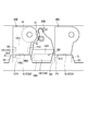
- FIG. 1 is a diagram illustrating a schematic configuration of a color printer according to an embodiment of the present invention. It is a perspective view showing the state where the cover of the main part case was opened. It is a perspective view showing the state where a drum cartridge was pulled out from a main part case.
- FIG. 9 is a perspective view illustrating a state in which a developing cartridge is pulled out from a main body housing. It is a perspective view (a), (b) which shows a drum cartridge.
- FIGS. 3A and 3B are perspective views showing a developing cartridge. It is a perspective view showing composition of a main part case.
- FIG. 3 is a diagram illustrating a relationship between each cartridge and a stopper and the like.
- FIG. 7 is a perspective view illustrating a state where the drum cartridge contacts a stopper.
- FIG. 9 is a perspective view illustrating a state where the developing cartridge is in contact with a stopper. It is a figure showing the 1st modification of the present invention.
- FIG. 13 is a perspective view showing each cartridge according to a first modification. It is a perspective view showing the 2nd modification of the present invention. It is a figure showing the 3rd modification of the present invention.
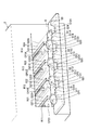
- the color printer 1 includes a main body casing 2, a paper feeding unit 3, an image forming unit 4, and a paper discharging unit 21.
- the paper supply unit 3 supplies the paper P to the image forming unit 4.
- the image forming unit 4 forms an image on the sheet P.
- the paper discharge unit 21 discharges the paper P.
- the paper discharge unit 21 is located at the upper part of the main body housing 2.
- the paper discharge unit 21 is located above an intermediate transfer belt 63 described later.
- the paper discharge unit 21 includes the discharge roller 9 and a paper discharge surface.
- the discharge roller 9 conveys the paper P toward the discharge surface.
- the paper feed unit 3 is located at a lower portion in the main body housing 2.
- the paper feed unit 3 includes a paper feed tray 31 and a paper feed mechanism 32.
- the paper feed tray 31 is detachable from the main body housing 2.
- the paper feed mechanism 32 conveys the paper P from the paper feed tray 31 to the image forming unit 4.
- the image forming section 4 includes a first drum cartridge 40A, a second drum cartridge 40B, a third drum cartridge 40C, and a fourth drum cartridge 40D, and a first developing cartridge 50A, a second developing cartridge 50B, a third developing cartridge 50C, 4 includes a developing cartridge 50D, an exposing device SU, a transfer unit 60, and a fixing unit 70.
- Each of the drum cartridges 40A to 40D has a photosensitive drum 41, a drum frame F1, and a charger (not shown).
- the photosensitive drum 41 is rotatable about a first axis X1 extending in a first direction.
- the drum cartridges 40A to 40D are arranged in a first direction and a second direction orthogonal to the vertical direction.
- drum cartridges 40A to 40D and the developing cartridges 50A to 50D are mounted on the main body casing 2, the drum cartridges 40A to 40D are separated from the developing cartridges 50A to 50D in the first direction and the second direction orthogonal to the vertical direction. line up.
- the first drum cartridge 40A is closer to a drive roller 61 described later than the second drum cartridge 40B in the second direction.
- the second drum cartridge 40B is closer to the drive roller 61 than the third drum cartridge 40C in the second direction.
- the third drum cartridge 40C is closer to the drive roller 61 than the fourth drum cartridge 40D in the second direction.
- Each of the developing cartridges 50A to 50D contains a different color developer.
- Each of the developing cartridges 50A to 50D has a developing roller 51 and a developing frame F2.
- the developing frame F2 contains a developer.
- the developing roller 51 is rotatable about a second axis X2 extending in the first direction.
- Each of the developing cartridges 50A to 50D is arranged in the second direction.
- Each of the developing cartridges 50A to 50D is positioned between a contact position where the developing roller 51 contacts the photosensitive drum 41 (the position in FIG. 1) and a separating position where the developing roller 51 separates from the photosensitive drum 41 (the position in FIG. 8). It is movable.
- Each of the developing cartridges 50A to 50D is movable between a contact position and a separated position by a mechanism (not shown).
- the first developing cartridge 50A is located between the first drum cartridge 40A and the second drum cartridge 40B in the second direction.
- the second developing cartridge 50B is located between the second drum cartridge 40B and the third drum cartridge 40C in the second direction.
- the third developing cartridge 50C is located between the third drum cartridge 40C and the fourth drum cartridge 40D in the second direction.
- the fourth developing cartridge 50D is farther from the drive roller 61 than the fourth drum cartridge 40D in the second direction.
- the exposure apparatus SU is located below each of the drum cartridges 40A to 40D.
- the exposure device SU emits a laser beam to each photosensitive drum 41.
- the transfer unit 60 is located between the four photosensitive drums 41 and the paper discharge unit 21.
- the transfer unit 60 includes a drive roller 61, a driven roller 62, an intermediate transfer belt 63, four primary transfer rollers 64, and a secondary transfer roller 65.
- the intermediate transfer belt 63 is an endless belt.
- the intermediate transfer belt 63 is located above the drum cartridges 40A to 40D and the developing cartridges 50A to 50D when the drum cartridges 40A to 40D and the developing cartridges 50A to 50D are mounted on the main body casing 2.
- the driving roller 61 and the driven roller 62 are located inside the intermediate transfer belt 63.
- the intermediate transfer belt 63 is supported by a driving roller 61 and a driven roller 62 in a state where tension is applied.
- the primary transfer roller 64 is located inside the intermediate transfer belt 63.
- the primary transfer roller 64 and the photosensitive drum 41 sandwich the intermediate transfer belt 63.
- the secondary transfer roller 65 is located outside the intermediate transfer belt 63.
- the secondary transfer roller 65 and the drive roller 61 sandwich the intermediate transfer belt 63.
- the fixing unit 70 is located on the intermediate transfer belt 63.
- the fixing unit 70 includes a heating roller 71 and a pressure roller 72.
- the pressure roller 72 is pressed by the heating roller 71.
- the charger charges the surface of the photosensitive drum 41.
- the exposure device SU exposes the surface of the photosensitive drum 41 to light.
- an electrostatic latent image is formed on the photosensitive drum 41.
- the developing roller 51 supplies a developer to the electrostatic latent image on the photosensitive drum 41. As a result, a developer image is formed on the photosensitive drum 41. Then, the developer image on the photosensitive drum 41 is transferred onto the intermediate transfer belt 63.
- the main housing 2 has a cover C for opening and closing the opening of the main housing 2.
- the opening 22A is an opening for attaching and detaching each of the drum cartridges 40A to 40D and each of the developing cartridges 50A to 50D.
- the cover C has a first cover C1 and a second cover C2.
- the first cover C1 rotates around the lower end of the first cover C1.
- the first cover C1 opens and closes at least a part of the opening 22A.
- the first cover C1 has a guide portion G.
- the guide portion G has four convex portions G1, G2, G3, and G4, and four second guide surfaces G21, G22, G23, and G24.
- the convex portions G1 to G4 protrude above the second guide surfaces G21 to G24 when the covers C1 and C2 are open.
- the four convex portions G1, G2, G3, G4 have first guide surfaces G11, G12, G13, G14, respectively.
- the first guide surfaces G11 to G14 are the upper surfaces of the convex portions G1 to G4.
- the first guide surfaces G11 to G14 are surfaces that guide the drum cartridges 40A to 40D when the covers C1 and C2 are open.
- the first guide surfaces G11 to G14 support a later-described fourth drum outer surface 440 of the drum cartridges 40A to 40D when the drum cartridges 40A to 40D are attached to and detached from the main body housing 2.
- the first guide surfaces G11 to G14 are located above the second guide surfaces G21 to G24.
- the second guide surfaces G21 to G24 are surfaces for guiding the developing cartridges 50A to 50D when the first cover C1 and the second cover C2 are opened.
- Each of the second guide surfaces G21 to G24 supports a third developing outer surface 540 described later of each of the developing cartridges 50A to 50D when the developing cartridges 50A to 50D are attached to and detached from the main body housing 2.
- the second cover C2 rotates around the lower end of the second cover C2.
- the second cover C2 covers the opening 22A and the first cover C1.
- the second cover C2 may rotate in conjunction with the rotation of the first cover C1.
- the first cover C1 and the second cover C2 may be separately rotatable.
- the second cover C2 has a first stopper S1, a second stopper S2, a third stopper S3, a fourth stopper S4, and a fifth stopper S5.
- the stoppers S1 to S5 move at least one of the drum cartridges 40A to 40D and the developing cartridges 50A to 50D, more specifically, along a first direction from the inside of the main body housing 2 to the outside of the main body housing 2. It is a member that stops the movement.
- the first stopper S1 regulates the movement of the first drum cartridge 40A outward in the first direction.
- the second stopper S2 regulates the movement of the first developing cartridge 50A and the second drum cartridge 40B outward in the first direction.
- the third stopper S3 regulates the movement of the second developing cartridge 50B and the third drum cartridge 40C outward in the first direction.
- the fourth stopper S4 regulates the movement of the third developing cartridge 50C and the fourth drum cartridge 40D outward in the first direction.
- the fifth stopper S5 regulates the movement of the fourth developing cartridge 50D outward in the first direction.
- the stoppers S1 to S5 are located farther from the opening 22A than the guide portion G in the first direction with the first cover C1 and the second cover C2 opened.
- the structure of each of the stoppers S1 to S5 will be described later in detail.
- the drum cartridges 40A to 40D and the developing cartridges 50A to 50D can be independently attached to and detached from the main housing 2 in the first direction.
- Each of the drum cartridges 40A to 40D has the same structure.
- Each of the developing cartridges 50A to 50D has the same structure.
- the structures of the second drum cartridge 40B and the second developing cartridge 50B will be described as representatives.
- the second drum cartridge 40B includes a first drum outer surface 410, a first handle H1, a second drum outer surface 420, and a third drum outer surface 430.
- a drum handle HU1 a fourth drum outer surface 440, a first protrusion P1, and a first guide groove GG1.
- the first drum outer surface 410 is located at one end of the second drum cartridge 40B in the first direction.
- the first handle H1 is located on the first drum outer surface 410.
- the first handle H1 is located at one end of the drum frame F1 in the first direction.
- the first handle H1 is located below the first drum outer surface 410.
- the first handle H1 is exposed from the main housing 2 when the second drum cartridge 40B is mounted on the main housing 2 (see FIG. 2).
- the first handle H1 is located below the photosensitive drum 41 when the second drum cartridge 40B is mounted on the main housing 2 (see FIG. 2).
- the first handle H1 has a first portion H11, a second portion H12, and a third portion H13.
- the first portion H11 is disposed apart from the first drum outer surface 410 in the first direction.
- the second portion H12 connects one end of the first portion H11 in the second direction and the first drum outer surface 410.
- the third portion H13 is located away from the second portion H12 in the second direction.
- the third portion H13 connects the other end of the first portion H11 in the second direction and the first drum outer surface 410 to reinforce.
- the first drum outer surface 410, the second portion H12, the first portion H11, and the third portion H13 form a first recess B1. That is, the first handle H1 has the first recess B1.
- the first recess B1 is a through hole that penetrates from above to below.
- the first dent B1 allows the user's finger to be hooked when the user takes out the second drum cartridge 40B from the main body housing 2.
- the second drum outer surface 420 is located at the upper end of the second drum cartridge 40B.
- the third drum outer surface 430 is located at one end of the second drum cartridge 40B in the second direction.
- the photosensitive drum 41 is located at the other end of the second drum cartridge 40B in the second direction.
- the third drum outer surface 430 has a concave portion 431 that is concave toward the photosensitive drum 41.
- the drum handle HU1 has two concave portions 421 and 431.
- the drum handle HU1 is located in the first direction between one end of the drum frame F1 in the first direction and the other end of the drum frame F1 in the first direction.
- the drum handle HU1 is located above the first handle H1 when the second drum cartridge 40B is mounted on the main body casing 2.
- the recess 421 is located on the outer surface 420 of the second drum.
- the recess 421 is recessed downward from the second drum outer surface 420.
- the concave portion 431 is located on the third drum outer surface 430.
- the recess 431 is recessed toward the photosensitive drum 41.
- the fourth drum outer surface 440 comes into contact with the first guide surface G12.
- the first protrusion P1 and the first guide groove GG1 are located on the fourth drum outer surface 440.
- the first projection P1 projects downward from the outer surface 440 of the fourth drum.
- the first protrusion P1 is located at a position away from the first handle H1 in the first direction.
- the first protrusion P1 is located at one end of the fourth drum outer surface 440 in the second direction.
- the fourth drum outer surface 440 has one end connected to the third drum outer surface 430.
- the first protrusion P1 is located at one end of the fourth drum outer surface 440.
- the first guide groove GG1 is recessed upward from the outer surface 440 of the fourth drum.
- the first guide groove GG1 is located at the center of the fourth drum outer surface 440 in the second direction.
- the first guide groove GG1 extends in the first direction.
- One end of the first guide groove GG1 in the first direction is closer to the first handle H1 than the other end of the first guide groove GG1 in the first direction.
- the other end of the first guide groove GG1 in the first direction is open in the first direction.
- the second developing cartridge 50B includes a first developing outer surface 510, a second handle H2, a second developing outer surface 530, a developing handle HU2, and a third developing outer surface 530. It has a development outer surface 540, a second protrusion P2, and a second guide groove GG2.
- the first developing outer surface 510 is located at one end of the second developing cartridge 50B in the first direction.
- the second handle H2 is located on the first development outer surface 510.
- the second handle H2 is located at one end of the developing frame F2 in the first direction.
- the second handle H2 is exposed from the main housing 2 in a state where the second developing cartridge 50B is mounted on the main housing 2 (see FIG. 2).
- the second handle H2 is located below the developing roller 51 in a state where the second developing cartridge 50B is mounted on the main body casing 2.
- At least a portion of the second handle H2 is located below the first handle H1 when the drum cartridges 40A to 40D and the developing cartridges 50A to 50D are mounted on the main body casing 2 (see FIG. 2).
- the second handle H2 is located below the first developing outer surface 510.
- the second handle H2 has a fourth portion H21, a fifth portion H22, and a sixth portion H23.
- the fourth portion H21 is disposed apart from the first outer development surface 510 in the first direction.
- the fifth portion H22 connects one end of the fourth portion H21 in the second direction with the first development outer surface 510.
- the sixth portion H23 is disposed apart from the fifth portion H22 in the second direction.
- the sixth portion H23 connects the other end of the fourth portion H21 in the second direction and the first developing outer surface 510 to reinforce.
- the first outer development surface 510, the fifth portion H22, the fourth portion H21, and the sixth portion H23 form a second recess B2. That is, the second handle H2 has the second recess B2.
- the second recess B2 is a through hole that penetrates from above to below. The second recess B2 allows the user's finger to be hooked when the user takes out the second developing cartridge 50B from the main body housing 2.
- the second developing outer surface 530 is located at one end of the second developing cartridge 50B in the second direction.
- the development handle HU2 is located at the upper end of the second development outer surface 530.
- the developing handle HU2 protrudes from the second outer developing surface 530 in the second direction.
- the second developing outer surface 530 is a surface that intersects in the second direction.
- the second protrusion P ⁇ b> 2 is located below the second outer development surface 530.
- the second projection P2 projects from the second outer development surface 530 in the second direction.
- the second protrusion P2 is located at a position away from the second handle H2 in the first direction.
- the third developing outer surface 540 contacts the above-described second guide surface G22.
- the second guide groove GG2 is located on the third developing outer surface 540.
- the second guide groove GG2 is recessed upward from the third developing outer surface 540.
- the second guide groove GG2 is located at the center of the third outer development surface 540 in the second direction.
- the second guide groove GG2 extends in the first direction.
- One end of the second guide groove GG2 in the first direction is closer to the second handle H2 than the other end of the second guide groove GG2 in the first direction.
- the other end of the second guide groove GG2 in the first direction is open in the first direction.
- the first stopper S1, the second stopper S2, the third stopper S3, and the fourth stopper S4 have first guide surfaces G111, G112, G113, and G114, respectively.
- the first guide surfaces G111 to G114 are surfaces that support the fourth drum outer surface 440 of the drum cartridges 40A to 40D when the drum cartridges 40A to 40D are attached to and detached from the main body housing 2.
- the positions of the first guide surfaces G111 to G114 are the same as the positions of the first guide surfaces G11 to G14 of the guide portion G.
- the second guide surfaces G121, G122, G123, G124 are located between the stoppers S1 to S5.
- the second guide surfaces G121 to G124 are surfaces that support the third developing outer surfaces 540 of the developing cartridges 50A to 50D when the developing cartridges 50A to 50D are attached to and detached from the main body housing 2.
- the positions of the second guide surfaces G121 to G124 are the same as the positions of the second guide surfaces G21 to G24 of the guide portion G.
- the stoppers S1 to S5 protrude upward from the second guide surfaces G121 to G124.
- the main body housing 2 includes a first guide surface G211, G212, G213, G214, a second guide surface G221, G222, G223, G224, first guide rails R11, R12, R13, R14, and a second guide rail R21. , R22, R23, and R24.
- the first guide surfaces G211 to G214 are surfaces that support the fourth drum outer surfaces 440 of the drum cartridges 40A to 40D when the drum cartridges 40A to 40D are attached to and detached from the main body housing 2. In the vertical direction, the positions of the first guide surfaces G211 to G214 are the same as the positions of the first guide surfaces G11 to G14 of the guide portion G.
- the second guide surfaces G221 to G224 are surfaces that support the third developing outer surfaces 540 of the developing cartridges 50A to 50D when the developing cartridges 50A to 50D are attached to and detached from the main body housing 2. In the up-down direction, the positions of the second guide surfaces G221 to G224 are the same as the positions of the second guide surfaces G21 to G24 of the guide portion G.
- the first guide rails R11 to R14 are rails for guiding the drum cartridges 40A to 40D in the first direction.
- the first guide rails R11 to R14 extend in a first direction.
- the first guide rails R11 to R14 enter the first guide grooves GG1 (see FIG. 5) of the drum cartridges 40A to 40D, respectively.
- the second guide rails R21 to R24 guide the developing cartridges 50A to 50D in the first direction.
- the second guide rails R21 to R24 extend in the first direction.
- the second guide rails R21 to R24 enter the second guide grooves GG2 (see FIG. 6) of the developing cartridges 50A to 50D, respectively.
- the guide portion G has four concave portions CP1, CP2, CP3, and CP4. Each of the recesses CP1 to CP4 is recessed downward from each of the first guide surfaces G11 to G14. As shown in FIG. 8, when the second drum cartridge 40B rests on the first guide surface G12, the first protrusion P1 of the second drum cartridge 40B enters the recess CP2. Thus, the second drum cartridge 40B can move in the first direction without interfering with the guide portion G in the first direction.
- the relationship between the other concave portions CP1, CP3, and CP4 and the other drum cartridges 40A, 40C, and 40D is similarly configured.
- the main body casing 2 has concave portions CP21, CP22, CP23, and CP24 similar to the concave portions CP1, CP2, CP3, and CP4.
- the relationship between the concave portions CP21, CP22, CP23, and CP24 of the main body housing 2 and the drum cartridges 40A to 40D is the same as the relationship between the concave portions CP1 to CP4 of the guide portion G and the drum cartridges 40A to 40D.
- the relationship between the other recesses CP1, CP3, CP4 and the stoppers S1, S3, S4 is the same as the relationship between the recess CP2 and the second stopper S2 described above.
- the second developing cartridge 50B is large enough to pass between the two convex portions G2 and G3 of the guide portion G.
- a part of the second developing cartridge 50B in the first direction, specifically, the second handle H2 is large enough to pass between the second stopper S2 and the third stopper S3.
- the second protrusion P2 of the second developing cartridge 50B overlaps the third stopper S3 in the first direction.
- the structures of the second protrusions P2 and the stoppers S3 to S5 of the other developing cartridges 50A, 50C, and 50D are the same as the structures of the second protrusions P2 and the third stopper S3 of the second developing cartridge 50B described above.
- the handles H1, H2 of each cartridge are exposed to the outside through the opening 22A of the main body casing 2.
- the user grips the first handle H1 of the second drum cartridge 40B. Specifically, the user puts a finger into the first recess B1 of the second drum cartridge 40B.
- the user pulls the second drum cartridge 40B in the first direction.
- the second drum cartridge 40B is guided by the first guide surfaces G212, G12, G112 (see FIG. 7) and moves in the first direction.
- the user grips the second handle H2 of the second developing cartridge 50B. Specifically, the user puts a finger into the second recess B2 of the second developing cartridge 50B.
- the second developing cartridge 50B is guided by the second guide surfaces G222, G22, G122 (see FIG. 7) and moves in the first direction.
- the cartridges 40B and 50B can be mounted on the main housing 2 by reversing the above-described operation procedure.
- the drum cartridges 40A to 40D can be easily pulled out in the first direction. Since a finger can be inserted between the fourth portion H21 of the second handle H2 and the first developing outer surface 510, the developing cartridges 50A to 50D can be easily pulled out in the first direction.
- the first portion H11 is connected to the first drum outer surface 410 by the second portion H12 and the third portion H13, the first portion H11 is less likely to bend when a user hooks a finger on the first portion H11. Therefore, the deformation of the first portion H11 can be suppressed.
- the fourth portion H21 is connected to the first outer development surface 510 by the fifth portion H22 and the sixth portion H23, so that the fourth portion H21 is less likely to bend when the user hooks a finger on the fourth portion H21. Therefore, deformation of the fourth portion H21 can be suppressed.
- the first handle H1 is disposed below the first drum outer surface 410, it is possible to easily insert a finger into the first recess B1 between the first handle H1 and the first drum outer surface 410 from above.
- the second handle H2 is disposed below the first outer development surface 510, it is possible to easily insert a finger from above into the second recess B2 between the second handle H2 and the first outer development surface 510.
- the user's finger can be inserted into the first dent H1 or the second dent H2 from above or below, or both.
- both the drum cartridge (for example, 40A) and the developing cartridge (for example, 50A) have handles H1 and H2, both the drum cartridge and the developing cartridge can be easily pulled out in the first direction.
- the second cover C2 has the stoppers S1 to S5, even when the cartridge (for example, 40A) is pulled out from the main body casing 2 vigorously, the cartridge is prevented from falling off from the main body casing 2 (for example, S1). Can be suppressed.
- the developing roller 51 and the photosensitive drum 41 can be kept apart when the cartridge is attached or detached. Resistance can be reduced.
- the stoppers S1 to S5 are located farther from the opening 22A than the guide portion G, so that the cartridge can be pulled out of the opening 22A greatly, and the cartridge can be replaced. Work can be performed easily.
- the structure is smaller than the structure in which the stopper for the first developing cartridge 50A and the stopper for the second drum cartridge 40B are separated. Can be simplified.
- the third stopper S3 and the fourth stopper S4 also have a function of stopping the movement of the two cartridges with one stopper, so that the structure can be further simplified.
- each cartridge has the drum handle HU1 and the developing handle HU2, after the cartridge is pulled out in the first direction using the handles H1 and H2, it is possible to take out the cartridge upward using the drum handle HU1 and the developing handle HU2. it can.
- drum handle HU1 is formed by the concave portion 421 recessed from the second drum outer surface 420, it is possible to suppress the drum handle HU1 from projecting from the second drum outer surface 420.
- both the drum cartridge and the developing cartridge (for example, 40A and 50A) have the drum handle HU1 and the developing handle HU2, each cartridge can be easily taken out.
- the present invention is not limited to the above embodiment, but can be used in various forms as exemplified below.
- members having substantially the same structure as those of the above-described embodiment are denoted by the same reference numerals, and description thereof will be omitted.
- At least a part of the second handle H4 includes a drum cartridge 40A to 40D and a developing cartridge 50A to 50D as a main body casing. In the state of being mounted on the second cartridge 2, in the first direction, it overlaps at least a part of the drum cartridges 40A to 40D. In addition, at least a portion of the second handle H4 is closer to the drum frame F1 than the first handle H3 in the first direction when the drum cartridges 40A to 40D and the developing cartridges 50A to 50D are mounted on the main body housing 2. Located at a remote location.
- At least a part of the second handle H2 is located below the first handle H3 when the drum cartridges 40A to 40D and the developing cartridges 50A to 50D are mounted on the main body casing 2.
- the first handle H3 in this embodiment has a first portion H31, a second portion H32, and a third portion H33, as shown in FIG.
- the second portion H32 and the third portion H33 connect the first portion H31 and the first drum outer surface 410.
- the second portion H32 is located at one end of the first drum outer surface 410 in the second direction.
- the photosensitive drum 41 is located at the other end of the first drum outer surface 410 in the second direction.
- the third portion H33 is located at the upper end of the first portion H31.
- the third portion H33 is connected to the upper end of the second portion H32.
- a first dent B3 is formed between the first handle H3 and the first drum outer surface 410. That is, the first handle H3 has the first recess B3.
- the first recess B3 is recessed upward from below and recessed in the second direction.
- the second handle H4 has a fourth portion H41, a fifth portion H42, and a sixth portion H43.
- the fifth portion H42 and the sixth portion H43 connect the fourth portion H41 and the first outer development surface 510.
- the fifth portion H42 is located at the upper end of the fourth portion H41.
- the sixth portion H43 is located at one end of the fifth portion H42 in the second direction.
- the fourth portion H41 extends below the fifth portion H42 and the sixth portion H43.
- a third recess B4 is formed between the second handle H4 and the first outer development surface 510. That is, the second handle H4 has the second recess B4.
- the second recess B4 is recessed in the second direction and penetrates from above to below.
- the first portion H31 and the fourth portion H41 overlap in the first direction.
- the fourth portion H41 covers part of the first portion H31 in the first direction.
- the fourth portion H41 is located at a position further away from the first drum outer surface 410 in the first direction than the first portion H31 in the first direction.
- the fourth portion H41 and the first drum outer surface 410 overlap in the first direction.
- the fourth portion H41 extends to a position overlapping the first drum outer surface 410 in the first direction.
- the lower end of the fourth portion H41 is located lower than the lower end of the first portion H31.
- the area of the fourth portion H41 can be increased, and the finger can be more easily hooked on the fourth portion H41. can do.
- the fourth portion H41 is located at a position farther from the first drum outer surface 410 in the first direction than the first portion H31, it is easy to catch a finger on the fourth portion H41 of the developing cartridge (for example, 50A). Thereby, the attaching / detaching operation of the developing cartridge which is frequently exchanged can be easily performed.
- the fourth portion H41 extends to a position overlapping the first drum outer surface 410, the area of the fourth portion H41 can be further increased.
- the third portion H33 is located at the upper end of the first portion H31, it is possible to prevent the finger from accidentally entering the first recess B3 when the user hooks the finger on the fourth portion H41 from above.
- the fourth portion H41 partially covers the first portion H31, but the present invention is not limited to this.
- the fourth portion only needs to cover at least a part of the first portion.
- the fourth portion may cover the entire first portion.
- the first portion may cover at least a part of the fourth portion.
- the second cover C2 may have a stopper S6 different from the above embodiment. Specifically, the stopper S6 protrudes upward from the tip of the second cover C2 when the second cover C2 is opened. The stopper S6 extends from one end of the second cover C2 in the second direction to the other end. The stopper S6 can contact all cartridges (for example, 40B and 50B) in the first direction. This makes it possible to prevent all the cartridges from falling off from the main body housing 2 with one stopper S6.
- the second cover C2 has the second guide portion GS.
- the second guide portion GS includes five convex portions GS1, GS2, GS3, GS4, and GS5 (GS1 and GS2 are not shown) and four first guide surfaces G111 to G114 (G111 and G112 (Not shown) and four second guide surfaces G121 to G124 (G121 and G122 are not shown).
- the five protrusions GS1 to GS5 have the same shape as the stoppers S1 to S5 in the embodiment.
- the second guide portion GS is located between the guide portion G and the stopper S6 in the first direction when the first cover C1 and the second cover C2 are opened.
- each of the drum cartridges 40A to 40D has a structure in which the above-described first protrusion P1 is removed.
- each of the developing cartridges 50A to 50D has a structure in which the above-described second protrusion P2 is removed. This prevents each cartridge from interfering with the protrusions GS1 to GS5.
- Each cartridge is guided by one of the first guide surfaces G111 to G114 and the second guide surfaces G121 to G124.
- the main body casing 2 has four first marker portions M11, M12, M13, and M14.
- Each of the first marker portions M11 to M14 has a color corresponding to the color of each of the developing cartridges 50A to 50D.
- the first marker portions M11 to M14 are located at positions corresponding to the positions of the developing cartridges 50A to 50D.
- the stopper S6 has four second marker portions M21, M22, M23, M24.
- Each of the second marker portions M21 to M24 has a color corresponding to the color of each of the developing cartridges 50A to 50D.
- the second marker portions M21 to M24 are located at positions corresponding to the positions of the developing cartridges 50A to 50D.
- each of the developing cartridges 50A to 50D can be mounted at an appropriate position.
- the first recess B1 and the second recess B2 are holes penetrating vertically, but the present invention is not limited to this.
- at least one of the first dent and the second dent may be a dent that dents downward from above.
- at least one of the first dent and the second dent may be a dent that is dented upward from below.
- at least one of the first dent and the second dent may be a dent that is dented in the second direction.
- both the first dent B5 and the second dent B6 may be dents that are both concave in the second direction.
- the first recess B5 opens in the second direction on the side opposite to the developing cartridge (50B), and the second recess B6 holds the second recess B6. It may open in the direction opposite to the drum cartridge (40B).
- the first recess B5 is recessed from the adjacent drum cartridge 40A toward the corresponding developing cartridge 50B in the second direction.
- the second recess B6 is recessed from the adjacent developing cartridge 50B toward the corresponding drum cartridge 40A.
- the first recess B5 extends from one end of the drum cartridge 40B in the second direction to the other end of the drum cartridge 40B in the second direction (the photosensitive drum 41 is connected to the other end of the drum cartridge 40B in the second direction). (Located at the end).
- the second recess B6 is recessed in the second direction from the other end of the drum cartridge 40B in the second direction to one end of the drum cartridge 40B in the second direction.
- the first handle H5 has a first portion H51, a second portion H52, a third portion H53, and a seventh portion H54.
- the first portion H51 is disposed apart from the first drum outer surface 410 in the first direction.
- the second portion H52 connects one end of the first portion H51 on the side of the developing cartridge (50B) in the second direction to the first drum outer surface 410.
- the third portion H53 connects the upper end of the first portion H51 and the first drum outer surface 410.
- the seventh portion H54 connects the lower end of the first portion H51 and the first drum outer surface 410.
- the second handle H6 has a fourth portion H61, a fifth portion H62, a sixth portion H63, and an eighth portion H64.
- the fourth portion H61 is disposed apart from the first outer development surface 510 in the first direction.
- the fifth portion H62 connects one end of the fourth portion H61 on the drum cartridge (40B) side in the second direction and the first developing outer surface 510.
- the sixth portion H63 connects the upper end of the fourth portion H61 and the first outer development surface 510.
- the eighth portion H64 connects the lower end portion of the fourth portion H61 and the first outer development surface 510.
- the first recess B5 and the second recess B6 open in opposite directions, so that the user can easily pull out each cartridge.
- the first recess B5 is recessed in the second direction from one end of the drum cartridge 40B in the second direction to the other end of the drum cartridge 40B in the second direction
- the user's finger is placed on one end side in the second direction.
- the second recess B6 is recessed in the second direction from the other end of the drum cartridge 40B in the second direction to one end of the drum cartridge 40B in the second direction, the user's finger is moved to the other end in the second direction. From the second recess B6.
- the drum handle HU1 is formed by the two concave portions 421 and 431, but the present invention is not limited to this.
- the drum handle may be formed with only the concave portion 421, or may be formed with only the concave portion 431.
- the present invention is applied to the color printer 1, but the present invention is not limited to this, and the present invention may be applied to other image forming apparatuses, for example, a monochrome printer, a copier, a multifunction peripheral, and the like. Good.
Landscapes
- Physics & Mathematics (AREA)
- General Physics & Mathematics (AREA)
- Engineering & Computer Science (AREA)
- Computer Vision & Pattern Recognition (AREA)
- Electrophotography Configuration And Component (AREA)
Abstract
カートリッジを第1方向に容易に引き出すことを目的とする。画像形成装置は、本体筐体2と、ドラムカートリッジ40Aと、現像カートリッジ50Aを備える。ドラムカートリッジ40Aは、第1方向に延びる第1軸について回転可能な感光ドラム41と、第1凹みB1を有する第1ハンドルH1を有する。現像カートリッジ50Aは、第2凹みB2を有する第2ハンドルH2を有する。ドラムカートリッジ40Aおよび現像カートリッジ50Aは、第1方向に本体筐体2に着脱可能である。 第1ハンドルH1は、第1方向におけるドラムフレームF1の一端に位置し、ドラムカートリッジ40Aが本体筐体2に装着された状態において、本体筐体2から露出する。第2ハンドルH2は、第1方向における現像フレームF2の一端に位置し、現像カートリッジ50Aが本体筐体2に装着された状態において、本体筐体2から露出する。
Description
本発明は、本体筐体に着脱可能なドラムカートリッジおよび現像カートリッジを備える画像形成装置に関する。
従来、本体筐体に対してドラムカートリッジおよび現像カートリッジを、感光ドラムの回転軸に沿った方向である第1方向に着脱可能な画像形成装置が知られている(特許文献1参照)。この技術では、ドラムカートリッジおよび現像カートリッジは、それぞれ独立して、本体筐体に対して着脱可能となっている。各カートリッジの第1方向の側面は、ユーザによって掴むことが可能な凸部を有する。ユーザは、凸部を指で掴んで各カートリッジを引き出すことが可能となっている。
しかしながら、従来の技術では、カートリッジの引き出し作業が容易でないという問題がある。
そこで、本発明は、カートリッジを第1方向に容易に引き出すことができる画像形成装置を提供することを目的とする。
前記課題を解決するため、本発明に係る画像形成装置は、本体筐体と、第1方向に延びる第1軸について回転可能な感光ドラムと、ドラムフレームと、を有するドラムカートリッジであって、前記第1方向に前記本体筐体に着脱可能なドラムカートリッジと、前記第1方向に延びる第2軸について回転可能な現像ローラと、現像剤を収容可能な現像フレームと、を有する現像カートリッジであって、前記第1方向に前記本体筐体に着脱可能な現像カートリッジと、前記ドラムカートリッジおよび前記現像カートリッジが前記本体筐体に装着された状態において、前記ドラムカートリッジおよび前記現像カートリッジよりも上方に位置する中間転写ベルトと、を備える。
前記ドラムカートリッジは、前記第1方向における前記ドラムフレームの一端に位置する第1ハンドルであって、前記ドラムカートリッジが前記本体筐体に装着された状態において、前記本体筐体から露出された第1ハンドルであって、第1凹みを有する第1ハンドルを有する。
前記現像カートリッジは、前記第1方向における前記現像フレームの一端に位置する第2ハンドルであって、前記現像カートリッジが前記本体筐体に装着された状態において、前記本体筐体から露出された第2ハンドルであって、第2凹みを有する第2ハンドルを有する。
前記ドラムカートリッジは、前記第1方向における前記ドラムフレームの一端に位置する第1ハンドルであって、前記ドラムカートリッジが前記本体筐体に装着された状態において、前記本体筐体から露出された第1ハンドルであって、第1凹みを有する第1ハンドルを有する。
前記現像カートリッジは、前記第1方向における前記現像フレームの一端に位置する第2ハンドルであって、前記現像カートリッジが前記本体筐体に装着された状態において、前記本体筐体から露出された第2ハンドルであって、第2凹みを有する第2ハンドルを有する。
この構成によれば、第1凹みまたは第2凹みにユーザの指を入れることができるので、カートリッジを第1方向に容易に引き出すことができる。
また、前記画像形成装置は、前記中間転写ベルトの上方に位置する排紙部を備えていてもよい。
また、前記第1凹みは、ユーザが前記本体筐体から前記ドラムカートリッジを取り出す場合に、ユーザの指がフックされることを許容してもよい。
これによれば、第1凹みにユーザの指をフックさせることができる。
また、前記第2凹みは、ユーザが前記本体筐体から前記現像カートリッジを取り出す場合に、ユーザの指がフックされることを許容してもよい。
これによれば、第2凹みにユーザの指をフックさせることができる。
また、前記ドラムカートリッジと前記現像カートリッジは、それぞれ独立して、前記本体筐体に着脱可能であってもよい。
また、前記第1ハンドルは、前記ドラムカートリッジが前記本体筐体に装着された状態で、前記感光ドラムの下方に位置していてもよい。
また、前記第1凹みは、上方から下方に向けて凹んでいてもよい。
また、前記第1凹みは、下方から上方に向けて凹んでいてもよい。
また、前記第1凹みは、上方から下方に向けて貫通する貫通穴であってもよい。
また、前記ドラムカートリッジおよび前記現像カートリッジが前記本体筐体に装着された状態で、前記第1凹みは、前記ドラムカートリッジと前記現像カートリッジの並び方向である第2方向に凹んでいてもよい。
また、前記第2ハンドルは、前記現像カートリッジが前記本体筐体に装着された状態で、前記現像ローラの下方に位置していてもよい。
また、前記第2凹みは、上方から下方に向けて凹んでいてもよい。
また、前記第2凹みは、下方から上方に向けて凹んでいてもよい。
また、前記第2凹みは、上方から下方に向けて貫通する貫通穴であってもよい。
また、前記ドラムカートリッジおよび前記現像カートリッジが前記本体筐体に装着された状態で、前記第2凹みは、前記ドラムカートリッジと前記現像カートリッジの並び方向である第2方向に凹んでいてもよい。
また、前記第2ハンドルの少なくとも一部は、前記ドラムカートリッジおよび前記現像カートリッジが前記本体筐体に装着された状態において、前記第1方向において、前記ドラムカートリッジの少なくとも一部と重なり、前記第1方向において、前記第1ハンドルよりも前記ドラムフレームから離れた位置に位置していてもよい。
これによれば、第2ハンドルをユーザが掴みやすいので、交換頻度が高い現像カートリッジをより容易に交換することができる。
また、前記第2ハンドルの少なくとも一部は、前記ドラムカートリッジおよび前記現像カートリッジが前記本体筐体に装着された状態において、前記第1ハンドルよりも下方に位置していてもよい。
これによれば、ユーザの指を第2ハンドルに下からフックしやすいので、交換頻度が高い現像カートリッジをより容易に交換することができる。
また、前記ドラムカートリッジは、前記第1方向において、前記第1方向における前記ドラムフレームの一端部と前記第1方向における前記ドラムフレームの他端部との間に位置するドラムハンドルであって、前記ドラムカートリッジが前記本体筐体に装着された状態において、前記第1ハンドルの上方に位置するドラムハンドルであり、上方から下方に向けて凹むドラムハンドルを有していてもよい。
これによれば、ユーザは、第1ハンドルに指をフックしてドラムカートリッジを第1方向に引き出した後、ドラムハンドルを掴んでドラムカートリッジを上方に容易に取り出すことができる。
本発明によれば、カートリッジを第1方向に容易に引き出すことができる。
次に、本発明の一実施形態について、適宜図面を参照しながら詳細に説明する。なお、以下の説明においては、まず、画像形成装置の一例としてのカラープリンタ1の全体構成を説明する。
図1に示すように、カラープリンタ1は、本体筐体2と、給紙部3と、画像形成部4と、排紙部21と、を備える。給紙部3は、画像形成部4に用紙Pを供給する。画像形成部4は、用紙Pに画像を形成する。排紙部21は、用紙Pを排出する。
排紙部21は、本体筐体2の上部に位置する。排紙部21は、後述する中間転写ベルト63の上方に位置する。排紙部21は、排出ローラ9と、排紙面と、を備える。排出ローラ9は、用紙Pを排紙面に向けて搬送する。
給紙部3は、本体筐体2内の下部に位置する。給紙部3は、給紙トレイ31と、給紙機構32と、を備える。給紙トレイ31は、本体筐体2に着脱可能である。給紙機構32は、用紙Pを給紙トレイ31から画像形成部4に搬送する。
画像形成部4は、第1ドラムカートリッジ40A、第2ドラムカートリッジ40B、第3ドラムカートリッジ40Cおよび第4ドラムカートリッジ40Dと、第1現像カートリッジ50A、第2現像カートリッジ50B、第3現像カートリッジ50Cおよび第4現像カートリッジ50Dと、露光装置SUと、転写ユニット60と、定着ユニット70と、を備える。
各ドラムカートリッジ40A~40Dは、感光ドラム41と、ドラムフレームF1と、図示せぬ帯電器と、を有する。感光ドラム41は、第1方向に延びる第1軸X1について回転可能である。各ドラムカートリッジ40A~40Dは、第1方向および上下方向に直交する第2方向に並ぶ。
ドラムカートリッジ40A~40Dおよび現像カートリッジ50A~50Dが本体筐体2に装着された状態において、ドラムカートリッジ40A~40Dは、第1方向および上下方向に直交する第2方向において、現像カートリッジ50A~50Dと並ぶ。
第1ドラムカートリッジ40Aは、第2方向において、第2ドラムカートリッジ40Bよりも後述する駆動ローラ61に近い。第2ドラムカートリッジ40Bは、第2方向において、第3ドラムカートリッジ40Cよりも駆動ローラ61に近い。第3ドラムカートリッジ40Cは、第2方向において、第4ドラムカートリッジ40Dよりも駆動ローラ61に近い。
各現像カートリッジ50A~50Dは、それぞれ異なる色の現像剤を収容する。各現像カートリッジ50A~50Dは、現像ローラ51と、現像フレームF2と、を有する。現像フレームF2は、現像剤を収容する。現像ローラ51は、第1方向に延びる第2軸X2について回転可能である。各現像カートリッジ50A~50Dは、第2方向に並ぶ。各現像カートリッジ50A~50Dは、現像ローラ51が感光ドラム41に接触する接触位置(図1の位置)と、現像ローラ51が感光ドラム41から離間する離間位置(図8の位置)との間で移動可能となっている。各現像カートリッジ50A~50Dは、図示せぬ機構により、接触位置と離間位置との間で移動可能となっている。
第1現像カートリッジ50Aは、第2方向において、第1ドラムカートリッジ40Aと第2ドラムカートリッジ40Bの間に位置する。第2現像カートリッジ50Bは、第2方向において、第2ドラムカートリッジ40Bと第3ドラムカートリッジ40Cの間に位置する。第3現像カートリッジ50Cは、第2方向において、第3ドラムカートリッジ40Cと第4ドラムカートリッジ40Dの間に位置する。第4現像カートリッジ50Dは、第2方向において、第4ドラムカートリッジ40Dよりも駆動ローラ61から遠い。
露光装置SUは、各ドラムカートリッジ40A~40Dの下に位置する。露光装置SUは、レーザ光を各感光ドラム41に出射する。
転写ユニット60は、4つの感光ドラム41と排紙部21との間に位置する。転写ユニット60は、駆動ローラ61と、従動ローラ62と、中間転写ベルト63と、4つの1次転写ローラ64と、2次転写ローラ65と、を備える。
中間転写ベルト63は、無端状のベルトである。中間転写ベルト63は、ドラムカートリッジ40A~40Dおよび現像カートリッジ50A~50Dが本体筐体2に装着された状態において、ドラムカートリッジ40A~40Dおよび現像カートリッジ50A~50Dよりも上方に位置する。駆動ローラ61および従動ローラ62は、中間転写ベルト63の内側に位置する。中間転写ベルト63は、テンションが付与された状態で、駆動ローラ61と従動ローラ62に支持されている。
1次転写ローラ64は、中間転写ベルト63の内側に位置する。1次転写ローラ64と感光ドラム41は、中間転写ベルト63を挟む。
2次転写ローラ65は、中間転写ベルト63の外側に位置する。2次転写ローラ65と駆動ローラ61は、中間転写ベルト63を挟む。
定着ユニット70は、中間転写ベルト63の上に位置する。定着ユニット70は、加熱ローラ71と、加圧ローラ72と、を備える。加圧ローラ72は、加熱ローラ71に押圧される。
まず、帯電器が、感光ドラム41の表面を帯電させる。その後、露光装置SUが、感光ドラム41の表面を露光する。これにより、感光ドラム41上に静電潜像が形成される。
次いで、現像ローラ51が、感光ドラム41上の静電潜像に現像剤を供給する。これにより、感光ドラム41上に現像剤像が形成される。そして、感光ドラム41上の現像剤像は、中間転写ベルト63上に転写される。
用紙Pが中間転写ベルト63と2次転写ローラ65の間を通過するときに、中間転写ベルト63上の現像剤像は、用紙P上に転写される。その後、用紙P上の現像剤像は、定着ユニット70で定着される。次いで、用紙Pは、排出ローラ9によって排紙部21に排出される。
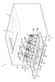
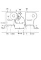
図2に示すように、本体筐体2は、本体筐体2の開口を開閉するカバーCを有する。開口22Aは、各ドラムカートリッジ40A~40Dおよび各現像カートリッジ50A~50Dを着脱するための開口である。
カバーCは、第1カバーC1と、第2カバーC2と、を有する。
第1カバーC1は、第1カバーC1の下端を中心に回動する。第1カバーC1は、開口22Aの少なくとも一部を開閉する。第1カバーC1は、ガイド部Gを有する。
ガイド部Gは、4つの凸部G1,G2,G3,G4と、4つの第2ガイド面G21,G22,G23,G24と、を有する。各凸部G1~G4は、各カバーC1,C2が開いた状態において、各第2ガイド面G21~G24よりも上に突出する。
4つの凸部G1,G2,G3,G4は、それぞれ第1ガイド面G11,G12,G13,G14を有する。詳しくは、第1ガイド面G11~G14は、凸部G1~G4の上面である。
第1ガイド面G11~G14は、各カバーC1,C2が開いた状態において、ドラムカートリッジ40A~40Dをガイドする面である。第1ガイド面G11~G14は、ドラムカートリッジ40A~40Dを本体筐体2に対して着脱するときに、ドラムカートリッジ40A~40Dの後述する第4ドラム外表面440を支持する。第1ガイド面G11~G14は、第2ガイド面G21~G24よりも上に位置する。
各第2ガイド面G21~G24は、第1カバーC1および第2カバーC2を開いた状態において、現像カートリッジ50A~50Dをガイドする面である。各第2ガイド面G21~G24は、現像カートリッジ50A~50Dを本体筐体2に対して着脱するときに、現像カートリッジ50A~50Dの後述する第3現像外表面540を支持する。
第2カバーC2は、第2カバーC2の下端を中心に回動する。第2カバーC2は、開口22Aおよび第1カバーC1を覆う。なお、第2カバーC2は、第1カバーC1の回動に連動して回動してもよい。また、第1カバーC1と第2カバーC2が、それぞれ別々に回動可能となっていてもよい。
第2カバーC2は、第1ストッパS1と、第2ストッパS2と、第3ストッパS3と、第4ストッパS4と、第5ストッパS5と、を有する。各ストッパS1~S5は、各ドラムカートリッジ40A~40Dおよび各現像カートリッジ50A~50Dの少なくとも1つのカートリッジの移動、詳しくは、本体筐体2内から本体筐体2の外へ向かう第1方向に沿った移動を止める部材である。
詳しくは、第1ストッパS1は、第1ドラムカートリッジ40Aの第1方向外側への移動を規制する。第2ストッパS2は、第1現像カートリッジ50Aおよび第2ドラムカートリッジ40Bの第1方向外側への移動を規制する。
第3ストッパS3は、第2現像カートリッジ50Bおよび第3ドラムカートリッジ40Cの第1方向外側への移動を規制する。第4ストッパS4は、第3現像カートリッジ50Cおよび第4ドラムカートリッジ40Dの第1方向外側への移動を規制する。第5ストッパS5は、第4現像カートリッジ50Dの第1方向外側への移動を規制する。
各ストッパS1~S5は、第1カバーC1および第2カバーC2を開いた状態で、第1方向において、ガイド部Gよりも開口22Aから遠い位置に位置する。なお、各ストッパS1~S5の構造については、後で詳述する。
図3および図4に示すように、ドラムカートリッジ40A~40Dおよび現像カートリッジ50A~50Dは、それぞれ独立して、本体筐体2に対して第1方向に着脱可能となっている。各ドラムカートリッジ40A~40Dは、同一の構造となっている。各現像カートリッジ50A~50Dは、同一の構造となっている。以下の説明では、第2ドラムカートリッジ40Bおよび第2現像カートリッジ50Bの構造を、代表して説明する。
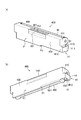
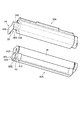
図5(a),(b)に示すように、第2ドラムカートリッジ40Bは、第1ドラム外表面410と、第1ハンドルH1と、第2ドラム外表面420と、第3ドラム外表面430と、ドラムハンドルHU1と、第4ドラム外表面440と、第1突起P1と、第1ガイド溝GG1と、を有する。第1ドラム外表面410は、第2ドラムカートリッジ40Bの第1方向の一端に位置する。第1ハンドルH1は、第1ドラム外表面410に位置する。
第1ハンドルH1は、第1方向におけるドラムフレームF1の一端に位置する。第1ハンドルH1は、第1ドラム外表面410の下部に位置する。第1ハンドルH1は、第2ドラムカートリッジ40Bが本体筐体2に装着された状態において、本体筐体2から露出される(図2参照)。第1ハンドルH1は、第2ドラムカートリッジ40Bが本体筐体2に装着された状態で、感光ドラム41の下方に位置する(図2参照)。
第1ハンドルH1は、第1部位H11と、第2部位H12と、第3部位H13と、を有する。第1部位H11は、第1ドラム外表面410から第1方向に離れて配置される。第2部位H12は、第1部位H11の第2方向の一端部と第1ドラム外表面410とを連結する。
第3部位H13は、第2方向において、第2部位H12から離れて配置されている。第3部位H13は、第1部位H11の第2方向の他端部と第1ドラム外表面410とを連結して補強する。
第1ドラム外表面410、第2部位H12、第1部位H11および第3部位H13は、第1凹みB1を形成する。つまり、第1ハンドルH1は、第1凹みB1を有する。第1凹みB1は、上方から下方に向けて貫通する貫通穴である。第1凹みB1は、ユーザが本体筐体2から第2ドラムカートリッジ40Bを取り出す場合に、ユーザの指がフックされることを許容する。
第2ドラム外表面420は、第2ドラムカートリッジ40Bの上端に位置する。
第3ドラム外表面430は、第2方向において、第2ドラムカートリッジ40Bの一端に位置する。なお、感光ドラム41は、第2方向において、第2ドラムカートリッジ40Bの他端に位置する。第3ドラム外表面430は、感光ドラム41に向けて凹む凹部431を有する。
ドラムハンドルHU1は、2つの凹部421,431を有する。ドラムハンドルHU1は、第1方向において、第1方向におけるドラムフレームF1の一端部と第1方向におけるドラムフレームF1の他端部との間に位置する。ドラムハンドルHU1は、第2ドラムカートリッジ40Bが本体筐体2に装着された状態において、第1ハンドルH1の上方に位置する。凹部421は、第2ドラム外表面420に位置する。凹部421は、第2ドラム外表面420から下方に向けて凹む。凹部431は、第3ドラム外表面430に位置する。凹部431は、感光ドラム41に向けて凹む。
図5(b)に示すように、第4ドラム外表面440は、第1ガイド面G12と接触する。第1突起P1および第1ガイド溝GG1は、第4ドラム外表面440に位置する。
第1突起P1は、第4ドラム外表面440から下方に突出する。第1突起P1は、第1ハンドルH1から第1方向に離れた位置に位置する。第1突起P1は、第2方向において、第4ドラム外表面440の一端に位置する。詳しくは、第4ドラム外表面440は、第3ドラム外表面430と接続される一端を有する。第1突起P1は、第4ドラム外表面440の一端に位置する。
第1ガイド溝GG1は、第4ドラム外表面440から上方に向けて凹んでいる。第1ガイド溝GG1は、第2方向において、第4ドラム外表面440の中央に位置する。第1ガイド溝GG1は、第1方向に延びている。第1ガイド溝GG1の第1方向の一端は、第1ガイド溝GG1の第1方向の他端よりも第1ハンドルH1に近い。第1ガイド溝GG1の第1方向の他端は、第1方向に開口している。
図6(a),(b)に示すように、第2現像カートリッジ50Bは、第1現像外表面510と、第2ハンドルH2と、第2現像外表面530と、現像ハンドルHU2と、第3現像外表面540と、第2突起P2と、第2ガイド溝GG2と、を有する。第1現像外表面510は、第2現像カートリッジ50Bの第1方向の一端に位置する。第2ハンドルH2は、第1現像外表面510に位置する。
第2ハンドルH2は、第1方向における現像フレームF2の一端に位置する。第2ハンドルH2は、第2現像カートリッジ50Bが本体筐体2に装着された状態において、本体筐体2から露出される(図2参照)。第2ハンドルH2は、第2現像カートリッジ50Bが本体筐体2に装着された状態で、現像ローラ51の下方に位置する。第2ハンドルH2の少なくとも一部は、ドラムカートリッジ40A~40Dおよび現像カートリッジ50A~50Dが本体筐体2に装着された状態において、第1ハンドルH1よりも下方に位置する(図2参照)。
第2ハンドルH2は、第1現像外表面510の下部に位置する。第2ハンドルH2は、第4部位H21と、第5部位H22と、第6部位H23と、を有する。第4部位H21は、第1現像外表面510から第1方向に離れて配置される。第5部位H22は、第4部位H21の第2方向の一端部と第1現像外表面510とを連結する。
第6部位H23は、第2方向において、第5部位H22から離れて配置されている。第6部位H23は、第4部位H21の第2方向の他端部と第1現像外表面510とを連結して補強する。
第1現像外表面510、第5部位H22、第4部位H21および第6部位H23は、第2凹みB2を形成する。つまり、第2ハンドルH2は、第2凹みB2を有する。第2凹みB2は、上方から下方に向けて貫通する貫通穴である。第2凹みB2は、ユーザが本体筐体2から第2現像カートリッジ50Bを取り出す場合に、ユーザの指がフックされることを許容する。
第2現像外表面530は、第2方向において、第2現像カートリッジ50Bの一端に位置する。現像ハンドルHU2は、第2現像外表面530の上端に位置する。現像ハンドルHU2は、第2現像外表面530から第2方向に突出する。
第2現像外表面530は、第2方向に交差する面である。第2突起P2は、第2現像外表面530の下部に位置する。第2突起P2は、第2現像外表面530から第2方向に突出する。第2突起P2は、第2ハンドルH2から第1方向に離れた位置に位置する。
図6(a)に示すように、第3現像外表面540は、前述した第2ガイド面G22に接触する。第2ガイド溝GG2は、第3現像外表面540に位置する。
第2ガイド溝GG2は、第3現像外表面540から上方に向けて凹んでいる。第2ガイド溝GG2は、第2方向において、第3現像外表面540の中央に位置する。第2ガイド溝GG2は、第1方向に延びている。第2ガイド溝GG2の第1方向の一端は、第2ガイド溝GG2の第1方向の他端よりも第2ハンドルH2に近い。第2ガイド溝GG2の第1方向の他端は、第1方向に開口している。
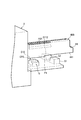
図7に示すように、第1ストッパS1、第2ストッパS2、第3ストッパS3および第4ストッパS4は、それぞれ第1ガイド面G111,G112,G113,G114を有する。第1ガイド面G111~G114は、ドラムカートリッジ40A~40Dを本体筐体2に対して着脱するときに、ドラムカートリッジ40A~40Dの第4ドラム外表面440を支持する面である。上下方向において、第1ガイド面G111~G114の位置は、ガイド部Gの第1ガイド面G11~G14の位置と同じである。
ストッパS1~S5のそれぞれの間には、第2ガイド面G121,G122,G123,G124が位置する。第2ガイド面G121~G124は、現像カートリッジ50A~50Dを本体筐体2に対して着脱するときに、現像カートリッジ50A~50Dの第3現像外表面540を支持する面である。上下方向において、第2ガイド面G121~G124の位置は、ガイド部Gの第2ガイド面G21~G24の位置と同じである。ストッパS1~S5は、第2ガイド面G121~G124から上に突出する。
本体筐体2は、第1ガイド面G211,G212,G213,G214と、第2ガイド面G221,G222,G223,G224と、第1ガイドレールR11,R12,R13,R14と、第2ガイドレールR21,R22,R23,R24と、を有している。
第1ガイド面G211~G214は、ドラムカートリッジ40A~40Dを本体筐体2に対して着脱するときに、ドラムカートリッジ40A~40Dの第4ドラム外表面440を支持する面である。上下方向において、第1ガイド面G211~G214の位置は、ガイド部Gの第1ガイド面G11~G14の位置と同じである。
第2ガイド面G221~G224は、現像カートリッジ50A~50Dを本体筐体2に対して着脱するときに、現像カートリッジ50A~50Dの第3現像外表面540を支持する面である。上下方向において、第2ガイド面G221~G224の位置は、ガイド部Gの第2ガイド面G21~G24の位置と同じである。
第1ガイドレールR11~R14は、ドラムカートリッジ40A~40Dを第1方向に案内するレールである。第1ガイドレールR11~R14は、第1方向に延びる。第1ガイドレールR11~R14は、それぞれ、ドラムカートリッジ40A~40Dの第1ガイド溝GG1(図5参照)に入る。
第2ガイドレールR21~R24は、現像カートリッジ50A~50Dを第1方向に案内するレールである。第2ガイドレールR21~R24は、第1方向に延びる。第2ガイドレールR21~R24は、それぞれ、現像カートリッジ50A~50Dの第2ガイド溝GG2(図6参照)に入る。
ガイド部Gは、4つの凹部CP1,CP2,CP3,CP4を有する。各凹部CP1~CP4は、各第1ガイド面G11~G14から下方に向けて凹む。図8に示すように、第2ドラムカートリッジ40Bが第1ガイド面G12上に載った状態において、第2ドラムカートリッジ40Bの第1突起P1は、凹部CP2に入る。これにより、第2ドラムカートリッジ40Bは、ガイド部Gと第1方向において干渉することなく、第1方向に移動可能となっている。
凹部CP2は、第1方向において、第2ストッパS2と重なっている。そのため、図9に示すように、第2ドラムカートリッジ40Bを本体筐体2から引き出す際には、第1突起P1は、ガイド部Gの凹部CP2を通った後、第2ストッパS2に接触する。これにより、第2ドラムカートリッジ40Bの第1方向の移動が止められる。
なお、図7に示すように、その他の凹部CP1,CP3,CP4とその他のドラムカートリッジ40A,40C,40Dとの関係も同様に構成されている。また、本体筐体2は、凹部CP1,CP2,CP3,CP4と同様の凹部CP21,CP22,CP23,CP24を有する。本体筐体2の凹部CP21,CP22,CP23,CP24とドラムカートリッジ40A~40Dとの関係は、ガイド部Gの凹部CP1~CP4とドラムカートリッジ40A~40Dとの関係と同じである。また、その他の凹部CP1,CP3,CP4とストッパS1,S3,S4との関係は、上述した凹部CP2と第2ストッパS2との関係と同じである。
図8に示すように、第2現像カートリッジ50Bは、ガイド部Gの2つの凸部G2,G3の間を通過可能な大きさとなっている。第2現像カートリッジ50Bの第1方向の一部、詳しくは第2ハンドルH2は、第2ストッパS2と第3ストッパS3の間を通過可能な大きさとなっている。そして、第2現像カートリッジ50Bの第2突起P2は、第1方向において、第3ストッパS3と重なっている。
そのため、図10に示すように、第2現像カートリッジ50Bを本体筐体2から引き出す際には、まず、第2現像カートリッジ50Bは、ガイド部Gの2つの凸部G2,G3の間を通る。その後、第2現像カートリッジ50Bの第2ハンドルH2が、第2ストッパS2と第3ストッパS3の間を通った後、第2突起P2が第3ストッパS3に接触する。これにより、第2現像カートリッジ50Bの移動が止められる。
なお、その他の現像カートリッジ50A,50C,50Dの各第2突起P2とストッパS3~S5の構造は、上述した第2現像カートリッジ50Bの第2突起P2と第3ストッパS3の構造と同じである。
次に、第2ドラムカートリッジ40Bおよび第2現像カートリッジ50Bの着脱方法について説明する。なお、その他のカートリッジの着脱方法については、同様であるため、説明を省略する。
図2に示すように、第1カバーC1および第2カバーC2を開けると、本体筐体2の開口22Aを通して各カートリッジのハンドルH1,H2が外部に露出する。第2ドラムカートリッジ40Bを本体筐体2から取り外す場合には、ユーザは、第2ドラムカートリッジ40Bの第1ハンドルH1を掴む。詳しくは、ユーザは、第2ドラムカートリッジ40Bの第1凹みB1に指を入れる。
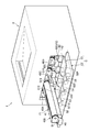
次いで、ユーザは、第2ドラムカートリッジ40Bを第1方向に引っ張る。これにより、図3に示すように、第2ドラムカートリッジ40Bは、各第1ガイド面G212,G12,G112(図7参照)にガイドされ、第1方向に移動する。
そして、図9に示すように、第2ドラムカートリッジ40Bの第1突起P1が第2ストッパS2に接触すると、第2ドラムカートリッジ40Bの第1方向の移動が止まる。そのため、第2ドラムカートリッジ40Bが本体筐体2から脱落することが抑制される。その後、ユーザは、ドラムハンドルHU1を掴む。次いで、ユーザは、第2ドラムカートリッジ40Bを上に持ち上げる。これにより、ユーザは、第2ドラムカートリッジ40Bを本体筐体2から容易に取り外すことができる。
図2に戻って、第2現像カートリッジ50Bを本体筐体2から取り外す場合には、ユーザは、第2現像カートリッジ50Bの第2ハンドルH2を掴む。詳しくは、ユーザは、第2現像カートリッジ50Bの第2凹みB2に指を入れる。
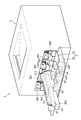
次いで、ユーザは、第2現像カートリッジ50Bを第1方向に引っ張る。これにより、図4に示すように、第2現像カートリッジ50Bは、各第2ガイド面G222,G22,G122(図7参照)にガイドされ、第1方向に移動する。
そして、図10に示すように、第2現像カートリッジ50Bの第2突起P2が第3ストッパS3に接触すると、第2現像カートリッジ50Bの第1方向の移動が止まる。そのため、第2現像カートリッジ50Bが本体筐体2から脱落することが抑制される。その後、ユーザは、現像ハンドルHU2を掴む。次いで、ユーザは、第2現像カートリッジ50Bを上に持ち上げる。これにより、ユーザは、第2現像カートリッジ50Bを本体筐体2から容易に取り外すことができる。
なお、各カートリッジ40B,50Bを本体筐体2に装着する方法は、前述した作業の手順を逆に行えばよい。
以上によれば、本実施形態において以下のような効果を得ることができる。
第1ハンドルH1の第1部位H11と第1ドラム外表面410の間に指を入れることができるので、ドラムカートリッジ40A~40Dを第1方向に容易に引き出すことができる。第2ハンドルH2の第4部位H21と第1現像外表面510の間に指を入れることができるので、現像カートリッジ50A~50Dを第1方向に容易に引き出すことができる。
第1ハンドルH1の第1部位H11と第1ドラム外表面410の間に指を入れることができるので、ドラムカートリッジ40A~40Dを第1方向に容易に引き出すことができる。第2ハンドルH2の第4部位H21と第1現像外表面510の間に指を入れることができるので、現像カートリッジ50A~50Dを第1方向に容易に引き出すことができる。
第1部位H11が、第2部位H12と第3部位H13によって第1ドラム外表面410に連結されることで、ユーザが指を第1部位H11に引っ掛けたときに第1部位H11が撓みにくくなるので、第1部位H11の変形を抑えることができる。第4部位H21が、第5部位H22と第6部位H23によって第1現像外表面510に連結されることで、ユーザが指を第4部位H21に引っ掛けたときに第4部位H21が撓みにくくなるので、第4部位H21の変形を抑えることができる。
第1ハンドルH1が第1ドラム外表面410の下部に配置されるので、第1ハンドルH1と第1ドラム外表面410との間の第1凹みB1に指を上から入れやすくすることができる。第2ハンドルH2が第1現像外表面510の下部に配置されるので、第2ハンドルH2と第1現像外表面510との間の第2凹みB2に指を上から入れやすくすることができる。
第1凹みH1および第2凹みH2が上下方向に貫通するので、ユーザの指を第1凹みH1または第2凹みH2に上または下、あるいは両方から差し込むことができる。
ドラムカートリッジ(例えば40A)および現像カートリッジ(例えば50A)の両方が、ハンドルH1,H2を有するので、ドラムカートリッジおよび現像カートリッジの両方を第1方向に容易に引き出すことができる。
第2カバーC2がストッパS1~S5を有するので、本体筐体2からカートリッジ(例えば40A)を勢いよく引き出した場合であっても、カートリッジが本体筐体2から脱落するのをストッパ(例えばS1)で抑えることができる。
第1ガイド面(例えばG11)を第2ガイド面(例えばG21)よりも上に配置したので、カートリッジの着脱時において、現像ローラ51と感光ドラム41を離しておくことができ、カートリッジの着脱時の抵抗を減らすことができる。
第1カバーC1および第2カバーC2を開いた状態において、ストッパS1~S5が、ガイド部Gよりも開口22Aから遠い位置に位置するので、カートリッジを開口22Aから大きく引き出すことができ、カートリッジの交換作業を容易に行うことができる。
第2ストッパS2が、第1現像カートリッジ50Aおよび第2ドラムカートリッジ40Bの両方に接触するので、例えば第1現像カートリッジ50A用のストッパと第2ドラムカートリッジ40B用のストッパを別にする構造に比べ、構造を簡易化することができる。同様に、第3ストッパS3および第4ストッパS4も、1つのストッパで2つのカートリッジの移動を止める機能を有するので、構造をより簡易化することができる。
各カートリッジがドラムハンドルHU1および現像ハンドルHU2を有するので、ハンドルH1,H2を利用してカートリッジを第1方向に引き出した後、ドラムハンドルHU1および現像ハンドルHU2を利用してカートリッジを上方に取り出すことができる。
ドラムハンドルHU1が、第2ドラム外表面420から凹む凹部421によって形成されているので、ドラムハンドルHU1が第2ドラム外表面420から突出するのを抑制することができる。
ドラムカートリッジおよび現像カートリッジの両方(例えば、40A,50A)が、ドラムハンドルHU1および現像ハンドルHU2を有するので、各カートリッジを上方に容易に取り出すことができる。
なお、本発明は前記実施形態に限定されることなく、以下に例示するように様々な形態で利用できる。以下の説明においては、前記実施形態と略同様の構造となる部材には同一の符号を付し、その説明は省略する。
図11に示すように、所定の色に対応した2つのカートリッジ(例えば、40A,50A)において、第2ハンドルH4の少なくとも一部は、ドラムカートリッジ40A~40Dおよび現像カートリッジ50A~50Dが本体筐体2に装着された状態において、第1方向において、ドラムカートリッジ40A~40Dの少なくとも一部と重なっている。また、第2ハンドルH4の少なくとも一部は、ドラムカートリッジ40A~40Dおよび現像カートリッジ50A~50Dが本体筐体2に装着された状態において、第1方向において、第1ハンドルH3よりもドラムフレームF1から離れた位置に位置する。
また、第2ハンドルH2の少なくとも一部は、ドラムカートリッジ40A~40Dおよび現像カートリッジ50A~50Dが本体筐体2に装着された状態において、第1ハンドルH3よりも下方に位置する。
この形態における第1ハンドルH3は、図12に示すように、第1部位H31と、第2部位H32と、第3部位H33と、を有する。第2部位H32および第3部位H33は、第1部位H31と第1ドラム外表面410とを連結する。第2部位H32は、第1ドラム外表面410の第2方向の一端に位置する。なお、この形態では、感光ドラム41は、第1ドラム外表面410の第2方向の他端に位置する。
第3部位H33は、第1部位H31の上端に位置する。第3部位H33は、第2部位H32の上端に繋がっている。第1ハンドルH3と第1ドラム外表面410との間には、第1凹みB3が形成されている。つまり、第1ハンドルH3は、第1凹みB3を有する。第1凹みB3は、下方から上方に向けて凹むとともに、第2方向に凹んでいる。
第2ハンドルH4は、第4部位H41と、第5部位H42と、第6部位H43と、を有する。第5部位H42および第6部位H43は、第4部位H41と第1現像外表面510とを連結する。第5部位H42は、第4部位H41の上端に位置する。
第6部位H43は、第5部位H42の第2方向の一端に位置する。第4部位H41は、第5部位H42および第6部位H43よりも下に延びている。第2ハンドルH4と第1現像外表面510との間には、第3凹みB4が形成されている。つまり、第2ハンドルH4は、第2凹みB4を有する。第2凹みB4は、第2方向に凹むとともに、上方から下方に向けて貫通している。
ドラムカートリッジ(例えば、40A)および現像カートリッジ(例えば、50A)が本体筐体2に装着された状態において、第1部位H31と第4部位H41は、第1方向において、重なっている。詳しくは、第4部位H41は、第1方向において、第1部位H31の一部を覆っている。言い換えると、第4部位H41は、第1方向において、第1部位H31よりも第1ドラム外表面410から第1方向に離れた位置に位置している。
また、第4部位H41と第1ドラム外表面410は、第1方向において、重なっている。言い換えると、第4部位H41は、第1方向において、第1ドラム外表面410と重なる位置まで延びている。また、第4部位H41の下端は、第1部位H31の下端よりも下に位置している。
また、第4部位H41と第1ドラム外表面410は、第1方向において、重なっている。言い換えると、第4部位H41は、第1方向において、第1ドラム外表面410と重なる位置まで延びている。また、第4部位H41の下端は、第1部位H31の下端よりも下に位置している。
この形態では、第1部位H31と第4部位H41が、第1方向において、重なっているので、第4部位H41の面積を大きくすることができ、第4部位H41に対して指をより引っ掛けやすくすることができる。
第4部位H41が第1部位H31よりも第1ドラム外表面410から第1方向に離れた位置に位置するので、現像カートリッジ(例えば50A)の第4部位H41に指を引っ掛けやすくなる。これにより、交換の頻度が高い現像カートリッジの着脱作業を容易に行うことができる。
第4部位H41が第1ドラム外表面410と重なる位置まで延びているため、第4部位H41の面積をより大きくすることができる。
第4部位H41の下端が第1部位H31の下端よりも下に位置するので、現像カートリッジ(例えば、50A)の交換時に、誤ってドラムカートリッジ(例えば、40A)の第1部位H31に指が引っかかるのを抑えることができる。
第3部位H33が第1部位H31の上端に位置するので、ユーザが第4部位H41に対して指を上から引っ掛ける際に、誤って第1凹みB3に指が入るのを抑えることができる。
なお、この形態では、第4部位H41で第1部位H31の一部を覆ったが、本発明はこれに限定されない。第4部位は第1部位の少なくとも一部を覆っていればよい。例えば、第4部位は、第1部位の全体を覆ってもよい。
また、図11の形態とは逆に、第1部位が、第4部位の少なくとも一部を覆っていてもよい。
図13に示すように、第2カバーC2は、前記実施形態とは異なるストッパS6を有していてもよい。具体的に、ストッパS6は、第2カバーC2を開いた状態において、第2カバーC2の先端から上に突出している。ストッパS6は、第2カバーC2の第2方向の一端から他端にわたって延びている。ストッパS6は、すべてのカートリッジ(例えば、40B,50B)と第1方向で接触可能となっている。これにより、1つのストッパS6で、すべてのカートリッジの本体筐体2からの脱落を抑制することができる。
なお、この構造では、第2カバーC2は、第2ガイド部GSを有している。第2ガイド部GSは、5つの凸部GS1,GS2,GS3,GS4,GS5(GS1,GS2は図示略)と、前記実施形態と同様の4つの第1ガイド面G111~G114(G111,G112は図示略)および4つの第2ガイド面G121~G124(G121,G122は図示略)と、を有している。5つの凸部GS1~GS5は、前記実施形態におけるストッパS1~S5と同一形状となっている。第2ガイド部GSは、第1カバーC1および第2カバーC2を開いているときに、第1方向においてガイド部GとストッパS6との間に位置する。
また、この構造では、各ドラムカートリッジ40A~40Dは、前述した第1突起P1が取り除かれた構造となっている。さらに、各現像カートリッジ50A~50Dは、前述した第2突起P2が取り除かれた構造となっている。これにより、各カートリッジが、凸部GS1~GS5と干渉しないようになっている。そして、各カートリッジは、第1ガイド面G111~G114および第2ガイド面G121~G124のいずれかでガイドされる。
また、本体筐体2は、4つの第1マーカ部M11,M12,M13,M14を有する。
各第1マーカ部M11~M14は、各現像カートリッジ50A~50Dの色に対応した色を有している。また、各第1マーカ部M11~M14は、各現像カートリッジ50A~50Dの位置に対応した位置に位置する。
各第1マーカ部M11~M14は、各現像カートリッジ50A~50Dの色に対応した色を有している。また、各第1マーカ部M11~M14は、各現像カートリッジ50A~50Dの位置に対応した位置に位置する。
ストッパS6は、4つの第2マーカ部M21,M22,M23,M24を有する。各第2マーカ部M21~M24は、各現像カートリッジ50A~50Dの色に対応した色を有している。また、各第2マーカ部M21~M24は、各現像カートリッジ50A~50Dの位置に対応した位置に位置する。
このようにマーカ部を設けることで、各現像カートリッジ50A~50Dを適正な位置に装着することができる。
前記実施形態では、第1凹みB1および第2凹みB2を上下方向に貫通する穴としたが、本発明はこれに限定されない。例えば、第1凹みおよび第2凹みの少なくとも一方を、上方から下方に向けて凹む凹みとしてもよい。また、第1凹みおよび第2凹みの少なくとも一方を、下方から上方に向けて凹む凹みとしてもよい。また、第1凹みおよび第2凹みの少なくとも一方を、第2方向に凹む凹みとしてもよい。
例えば、図14に示すように、第1凹みB5および第2凹みB6を、ともに第2方向に凹む凹みとしてもよい。この場合、所定の色に対応した2つのカートリッジ(例えば、40B,50B)において、第1凹みB5が第2方向において現像カートリッジ(50B)とは反対側に開口し、第2凹みB6が第2方向においてドラムカートリッジ(40B)とは反対側に開口してもよい。
言い換えると、第1凹みB5は、第2方向において、隣のドラムカートリッジ40Aから対応する現像カートリッジ50Bに向けて凹む。また、第2凹みB6は、隣の現像カートリッジ50Bから対応するドラムカートリッジ40Aに向けて凹む。
さらに言い換えると、第1凹みB5は、第2方向において、第2方向におけるドラムカートリッジ40Bの一端から第2方向におけるドラムカートリッジ40Bの他端(感光ドラム41は、第2方向におけるドラムカートリッジ40Bの他端に位置する。)に向けて凹む。また、第2凹みB6は、第2方向において、第2方向におけるドラムカートリッジ40Bの他端から第2方向におけるドラムカートリッジ40Bの一端に向けて凹む。
詳しくは、この形態において、第1ハンドルH5は、第1部位H51と、第2部位H52と、第3部位H53と、第7部位H54と、を有する。第1部位H51は、第1ドラム外表面410から第1方向に離れて配置される。第2部位H52は、第1部位H51の第2方向における現像カートリッジ(50B)側の一端部と第1ドラム外表面410とを連結する。
第3部位H53は、第1部位H51の上端部と第1ドラム外表面410とを連結する。
第7部位H54は、第1部位H51の下端部と第1ドラム外表面410とを連結する。
第7部位H54は、第1部位H51の下端部と第1ドラム外表面410とを連結する。
第2ハンドルH6は、第4部位H61と、第5部位H62と、第6部位H63と、第8部位H64と、を有する。第4部位H61は、第1現像外表面510から第1方向に離れて配置される。第5部位H62は、第4部位H61の第2方向におけるドラムカートリッジ(40B)側の一端部と第1現像外表面510とを連結する。
第6部位H63は、第4部位H61の上端部と第1現像外表面510とを連結する。第8部位H64は、第4部位H61の下端部と第1現像外表面510とを連結する。
この構造によれば、第1凹みB5と第2凹みB6が互いに反対方向に開口するので、ユーザが各カートリッジを容易に引き出すことができる。言い換えると、第1凹みB5が、第2方向において、第2方向におけるドラムカートリッジ40Bの一端から第2方向におけるドラムカートリッジ40Bの他端に向けて凹むので、ユーザの指を第2方向の一端側から第1凹みB5に差し込むことができる。また、第2凹みB6が、第2方向において、第2方向におけるドラムカートリッジ40Bの他端から第2方向におけるドラムカートリッジ40Bの一端に向けて凹むので、ユーザの指を第2方向の他端側から第2凹みB6に差し込むことができる。
前記実施形態では、ドラムハンドルHU1を2つの凹部421,431で形成したが、本発明はこれに限定されない。例えば、ドラムハンドルを、凹部421のみで形成してもよいし、凹部431のみで形成してもよい。
前記実施形態では、カラープリンタ1に本発明を適用したが、本発明はこれに限定されず、その他の画像形成装置、例えばモノクロのプリンタ、複写機、複合機などに本発明を適用してもよい。
前記した実施形態および変形例で説明した各要素を、任意に組み合わせて実施してもよい。
1 カラープリンタ
2 本体筐体
40A~40D ドラムカートリッジ
41 感光ドラム
50A~50D 現像カートリッジ
51 現像ローラ
63 中間転写ベルト
B1 第1凹み
B2 第2凹み
F1 ドラムフレーム
F2 現像フレーム
H1 第1ハンドル
H2 第2ハンドル
X1 第1軸
X2 第2軸
2 本体筐体
40A~40D ドラムカートリッジ
41 感光ドラム
50A~50D 現像カートリッジ
51 現像ローラ
63 中間転写ベルト
B1 第1凹み
B2 第2凹み
F1 ドラムフレーム
F2 現像フレーム
H1 第1ハンドル
H2 第2ハンドル
X1 第1軸
X2 第2軸
Claims (18)
- 本体筐体と、
第1方向に延びる第1軸について回転可能な感光ドラムと、ドラムフレームと、を有するドラムカートリッジであって、前記第1方向に前記本体筐体に着脱可能なドラムカートリッジと、
前記第1方向に延びる第2軸について回転可能な現像ローラと、現像剤を収容可能な現像フレームと、を有する現像カートリッジであって、前記第1方向に前記本体筐体に着脱可能な現像カートリッジと、
前記ドラムカートリッジおよび前記現像カートリッジが前記本体筐体に装着された状態において、前記ドラムカートリッジおよび前記現像カートリッジよりも上方に位置する中間転写ベルトと、を備え、
前記ドラムカートリッジは、前記第1方向における前記ドラムフレームの一端に位置する第1ハンドルであって、前記ドラムカートリッジが前記本体筐体に装着された状態において、前記本体筐体から露出された第1ハンドルであって、第1凹みを有する第1ハンドルを有し、
前記現像カートリッジは、前記第1方向における前記現像フレームの一端に位置する第2ハンドルであって、前記現像カートリッジが前記本体筐体に装着された状態において、前記本体筐体から露出された第2ハンドルであって、第2凹みを有する第2ハンドルを有することを特徴とする画像形成装置。 - 前記中間転写ベルトの上方に位置する排紙部を備えたことを特徴とする請求項1に記載の画像形成装置。
- 前記第1凹みは、ユーザが前記本体筐体から前記ドラムカートリッジを取り出す場合に、ユーザの指がフックされることを許容することを特徴とする請求項1または請求項2に記載の画像形成装置。
- 前記第2凹みは、ユーザが前記本体筐体から前記現像カートリッジを取り出す場合に、ユーザの指がフックされることを許容することを特徴とする請求項1から請求項3のいずれか1項に記載の画像形成装置。
- 前記ドラムカートリッジと前記現像カートリッジは、それぞれ独立して、前記本体筐体に着脱可能であることを特徴とする請求項1から請求項4のいずれか1項に記載の画像形成装置。
- 前記第1ハンドルは、前記ドラムカートリッジが前記本体筐体に装着された状態で、前記感光ドラムの下方に位置することを特徴とする請求項1から請求項5のいずれか1項に記載の画像形成装置。
- 前記第1凹みは、上方から下方に向けて凹むことを特徴とする請求項1から請求項6のいずれか1項に記載の画像形成装置。
- 前記第1凹みは、下方から上方に向けて凹むことを特徴とする請求項1から請求項6のいずれか1項に記載の画像形成装置。
- 前記第1凹みは、上方から下方に向けて貫通する貫通穴であることを特徴とする請求項1から請求項6のいずれか1項に記載の画像形成装置。
- 前記ドラムカートリッジおよび前記現像カートリッジが前記本体筐体に装着された状態で、前記第1凹みは、前記ドラムカートリッジと前記現像カートリッジの並び方向である第2方向に凹むことを特徴とする請求項1から請求項6のいずれか1項に記載の画像形成装置。
- 前記第2ハンドルは、前記現像カートリッジが前記本体筐体に装着された状態で、前記現像ローラの下方に位置することを特徴とする請求項1から請求項10のいずれか1項に記載の画像形成装置。
- 前記第2凹みは、上方から下方に向けて凹むことを特徴とする請求項1から請求項11のいずれか1項に記載の画像形成装置。
- 前記第2凹みは、下方から上方に向けて凹むことを特徴とする請求項1から請求項11のいずれか1項に記載の画像形成装置。
- 前記第2凹みは、上方から下方に向けて貫通する貫通穴であることを特徴とする請求項1から請求項11のいずれか1項に記載の画像形成装置。
- 前記ドラムカートリッジおよび前記現像カートリッジが前記本体筐体に装着された状態で、前記第2凹みは、前記ドラムカートリッジと前記現像カートリッジの並び方向である第2方向に凹むことを特徴とする請求項1から請求項11のいずれか1項に記載の画像形成装置。
- 前記第2ハンドルの少なくとも一部は、前記ドラムカートリッジおよび前記現像カートリッジが前記本体筐体に装着された状態において、前記第1方向において、前記ドラムカートリッジの少なくとも一部と重なり、前記第1方向において、前記第1ハンドルよりも前記ドラムフレームから離れた位置に位置することを特徴とする請求項1から請求項5のいずれか1項に記載の画像形成装置。
- 前記第2ハンドルの少なくとも一部は、前記ドラムカートリッジおよび前記現像カートリッジが前記本体筐体に装着された状態において、前記第1ハンドルよりも下方に位置することを特徴とする請求項1から請求項16のいずれか1項に記載の画像形成装置。
- 前記ドラムカートリッジは、前記第1方向において、前記第1方向における前記ドラムフレームの一端部と前記第1方向における前記ドラムフレームの他端部との間に位置するドラムハンドルであって、前記ドラムカートリッジが前記本体筐体に装着された状態において、前記第1ハンドルの上方に位置するドラムハンドルであり、上方から下方に向けて凹むドラムハンドルを有することを特徴とする請求項1から請求項17のいずれか一項に記載の画像形成装置。
Priority Applications (4)
| Application Number | Priority Date | Filing Date | Title |
|---|---|---|---|
| US16/793,100 US10969729B2 (en) | 2018-09-28 | 2020-02-18 | Image forming apparatus |
| US17/215,611 US11347176B2 (en) | 2018-09-28 | 2021-03-29 | Image forming apparatus |
| US17/733,023 US11880159B2 (en) | 2018-09-28 | 2022-04-29 | Image forming apparatus |
| US18/483,014 US20240036507A1 (en) | 2018-09-28 | 2023-10-09 | Image forming apparatus |
Applications Claiming Priority (2)
| Application Number | Priority Date | Filing Date | Title |
|---|---|---|---|
| JP2018-184469 | 2018-09-28 | ||
| JP2018184469A JP7010188B2 (ja) | 2018-09-28 | 2018-09-28 | 画像形成装置 |
Related Child Applications (1)
| Application Number | Title | Priority Date | Filing Date |
|---|---|---|---|
| US16/793,100 Continuation US10969729B2 (en) | 2018-09-28 | 2020-02-18 | Image forming apparatus |
Publications (1)
| Publication Number | Publication Date |
|---|---|
| WO2020066092A1 true WO2020066092A1 (ja) | 2020-04-02 |
Family
ID=69953072
Family Applications (1)
| Application Number | Title | Priority Date | Filing Date |
|---|---|---|---|
| PCT/JP2019/016287 WO2020066092A1 (ja) | 2018-09-28 | 2019-04-16 | 画像形成装置 |
Country Status (3)
| Country | Link |
|---|---|
| US (4) | US10969729B2 (ja) |
| JP (1) | JP7010188B2 (ja) |
| WO (1) | WO2020066092A1 (ja) |
Families Citing this family (2)
| Publication number | Priority date | Publication date | Assignee | Title |
|---|---|---|---|---|
| JP2022056493A (ja) * | 2020-09-30 | 2022-04-11 | 富士フイルムビジネスイノベーション株式会社 | 保護部材、保護部材付き交換部品、および画像形成装置 |
| US20230122291A1 (en) * | 2021-10-19 | 2023-04-20 | Jonathan Mohr | Case Cover for Covering the Back of a Computer Case |
Citations (7)
| Publication number | Priority date | Publication date | Assignee | Title |
|---|---|---|---|---|
| JP2006248645A (ja) * | 2005-03-09 | 2006-09-21 | Toshiba Corp | 画像形成装置 |
| JP2010102303A (ja) * | 2008-09-29 | 2010-05-06 | Canon Inc | 電子写真画像形成装置 |
| EP2296061A2 (en) * | 2009-09-11 | 2011-03-16 | Brother Kogyo Kabushiki Kaisha | Developer cartridge |
| JP2013182103A (ja) * | 2012-03-01 | 2013-09-12 | Sharp Corp | 画像形成装置 |
| JP2014071140A (ja) * | 2012-09-27 | 2014-04-21 | Canon Inc | プロセスカートリッジ |
| JP2017026737A (ja) * | 2015-07-21 | 2017-02-02 | 京セラドキュメントソリューションズ株式会社 | 現像装置及びそれを備えた画像形成装置 |
| JP2018072677A (ja) * | 2016-11-01 | 2018-05-10 | キヤノン株式会社 | 画像形成装置 |
Family Cites Families (22)
| Publication number | Priority date | Publication date | Assignee | Title |
|---|---|---|---|---|
| US4309779A (en) * | 1980-09-24 | 1982-01-12 | Paul W. Reichert | Personal urinal device useable by males and females |
| JPS60211472A (ja) | 1984-04-05 | 1985-10-23 | Konishiroku Photo Ind Co Ltd | 複写機 |
| US5341200A (en) | 1992-12-28 | 1994-08-23 | Xerox Corporation | Removable process unit with waste toner storage |
| US5678315A (en) * | 1994-08-15 | 1997-10-21 | Hartzell; Mark D. | Saw handle having a grip member perpendicular to and symmetrical about a saw blade |
| US6289557B1 (en) * | 1998-12-15 | 2001-09-18 | Barry F. Manson | Sanitary door handle assembly |
| US6484329B1 (en) * | 2001-01-24 | 2002-11-26 | Scott Duncan | Bladder-controlled stopper device |
| JP4107573B2 (ja) | 2002-09-10 | 2008-06-25 | 株式会社リコー | 画像形成装置 |
| KR100814425B1 (ko) * | 2003-02-20 | 2008-03-18 | 삼성전자주식회사 | 프로세스 카트리지 및 화상형성장치 |
| JP4664656B2 (ja) * | 2004-11-30 | 2011-04-06 | 京セラミタ株式会社 | 画像形成装置 |
| JP2007003660A (ja) | 2005-06-22 | 2007-01-11 | Murata Mach Ltd | 画像形成装置 |
| US20100127003A1 (en) * | 2006-10-25 | 2010-05-27 | Brasilata S/A Embalagens Metalicas | Suspension device for containers |
| JP5159225B2 (ja) | 2007-09-21 | 2013-03-06 | キヤノン株式会社 | 画像形成装置 |
| US8019252B2 (en) | 2009-02-26 | 2011-09-13 | Fuji Xerox Co., Ltd. | Removable member-holding device and image forming apparatus |
| JP5326656B2 (ja) | 2009-02-26 | 2013-10-30 | 富士ゼロックス株式会社 | 画像形成装置 |
| JP5419544B2 (ja) * | 2009-05-19 | 2014-02-19 | キヤノン株式会社 | カートリッジ及び画像形成装置 |
| US8583004B2 (en) * | 2010-12-27 | 2013-11-12 | Brother Kogyo Kabushiki Kaisha | Image forming apparatus having exposure unit moving mechanism |
| JP5771565B2 (ja) * | 2012-06-14 | 2015-09-02 | 京セラドキュメントソリューションズ株式会社 | 画像形成装置 |
| JP2015112777A (ja) | 2013-12-11 | 2015-06-22 | セイコーエプソン株式会社 | 記録装置 |
| US11096384B2 (en) * | 2015-01-19 | 2021-08-24 | Christina Jemail | Enhanced equine tool |
| JP6525601B2 (ja) | 2015-01-22 | 2019-06-05 | キヤノン株式会社 | 画像形成装置 |
| KR20160133168A (ko) * | 2015-05-12 | 2016-11-22 | 엘지전자 주식회사 | 이동 가능한 핸들을 갖는 가전제품 |
| JP2017194533A (ja) | 2016-04-19 | 2017-10-26 | キヤノン株式会社 | カートリッジ及び画像形成装置 |
-
2018
- 2018-09-28 JP JP2018184469A patent/JP7010188B2/ja active Active
-
2019
- 2019-04-16 WO PCT/JP2019/016287 patent/WO2020066092A1/ja active Application Filing
-
2020
- 2020-02-18 US US16/793,100 patent/US10969729B2/en active Active
-
2021
- 2021-03-29 US US17/215,611 patent/US11347176B2/en active Active
-
2022
- 2022-04-29 US US17/733,023 patent/US11880159B2/en active Active
-
2023
- 2023-10-09 US US18/483,014 patent/US20240036507A1/en active Pending
Patent Citations (7)
| Publication number | Priority date | Publication date | Assignee | Title |
|---|---|---|---|---|
| JP2006248645A (ja) * | 2005-03-09 | 2006-09-21 | Toshiba Corp | 画像形成装置 |
| JP2010102303A (ja) * | 2008-09-29 | 2010-05-06 | Canon Inc | 電子写真画像形成装置 |
| EP2296061A2 (en) * | 2009-09-11 | 2011-03-16 | Brother Kogyo Kabushiki Kaisha | Developer cartridge |
| JP2013182103A (ja) * | 2012-03-01 | 2013-09-12 | Sharp Corp | 画像形成装置 |
| JP2014071140A (ja) * | 2012-09-27 | 2014-04-21 | Canon Inc | プロセスカートリッジ |
| JP2017026737A (ja) * | 2015-07-21 | 2017-02-02 | 京セラドキュメントソリューションズ株式会社 | 現像装置及びそれを備えた画像形成装置 |
| JP2018072677A (ja) * | 2016-11-01 | 2018-05-10 | キヤノン株式会社 | 画像形成装置 |
Also Published As
| Publication number | Publication date |
|---|---|
| US10969729B2 (en) | 2021-04-06 |
| US20200183319A1 (en) | 2020-06-11 |
| US20240036507A1 (en) | 2024-02-01 |
| US20210216033A1 (en) | 2021-07-15 |
| US20220390890A1 (en) | 2022-12-08 |
| JP2020052359A (ja) | 2020-04-02 |
| JP7010188B2 (ja) | 2022-01-26 |
| US11347176B2 (en) | 2022-05-31 |
| US11880159B2 (en) | 2024-01-23 |
Similar Documents
| Publication | Publication Date | Title |
|---|---|---|
| RU2419121C2 (ru) | Электрофотографическое устройство для формирования изображения | |
| JP4569976B2 (ja) | 電子写真画像形成装置 | |
| KR102333305B1 (ko) | 화상형성장치의 본체에 장착가능한 현상 카트리지 | |
| US9348308B2 (en) | Process cartridge having force receiving portion and image forming apparatus including process cartridge | |
| WO2020066092A1 (ja) | 画像形成装置 | |
| US8032058B2 (en) | Electrophotographic image forming apparatus with developer cartridge lock member | |
| CN110879517A (zh) | 成像装置和处理盒 | |
| JP2009204656A (ja) | 画像形成装置 | |
| JP2010266854A (ja) | 電子写真画像形成装置、プロセスカートリッジ、及び、現像カートリッジ | |
| EP3796100B1 (en) | Cartridge and image forming apparatus | |
| JP4646214B2 (ja) | 画像形成装置 | |
| JP7211544B2 (ja) | 画像形成装置 | |
| EP2397918A1 (en) | Colour electrophotographic image forming apparatus | |
| JP2023040215A (ja) | 画像形成装置 | |
| JP5587236B2 (ja) | 現像カートリッジ | |
| JP7039314B2 (ja) | 画像形成装置 | |
| JP2008046442A (ja) | 画像形成装置 | |
| JP7483541B2 (ja) | カートリッジ及び画像形成装置 | |
| US11561502B2 (en) | Image forming apparatus including support frame with ground plate and contact spring | |
| JP7409077B2 (ja) | 画像形成装置 | |
| WO2020066090A1 (ja) | 画像形成装置 | |
| JP2010002622A (ja) | 画像形成装置 | |
| JP2010190974A (ja) | カートリッジ及び電子写真画像形成装置 | |
| JP2022146168A (ja) | 画像形成装置 | |
| JP2023018276A (ja) | シート給送装置、及び画像形成装置 |
Legal Events
| Date | Code | Title | Description |
|---|---|---|---|
| 121 | Ep: the epo has been informed by wipo that ep was designated in this application |
Ref document number: 19867102 Country of ref document: EP Kind code of ref document: A1 |
|
| NENP | Non-entry into the national phase |
Ref country code: DE |
|
| 122 | Ep: pct application non-entry in european phase |
Ref document number: 19867102 Country of ref document: EP Kind code of ref document: A1 |