WO2020044783A1 - 反転防止弁 - Google Patents
反転防止弁 Download PDFInfo
- Publication number
- WO2020044783A1 WO2020044783A1 PCT/JP2019/026504 JP2019026504W WO2020044783A1 WO 2020044783 A1 WO2020044783 A1 WO 2020044783A1 JP 2019026504 W JP2019026504 W JP 2019026504W WO 2020044783 A1 WO2020044783 A1 WO 2020044783A1
- Authority
- WO
- WIPO (PCT)
- Prior art keywords
- spool
- passage
- supply
- communication
- discharge passage
- Prior art date
- Legal status (The legal status is an assumption and is not a legal conclusion. Google has not performed a legal analysis and makes no representation as to the accuracy of the status listed.)
- Ceased
Links
Images

Classifications
-
- F—MECHANICAL ENGINEERING; LIGHTING; HEATING; WEAPONS; BLASTING
- F16—ENGINEERING ELEMENTS AND UNITS; GENERAL MEASURES FOR PRODUCING AND MAINTAINING EFFECTIVE FUNCTIONING OF MACHINES OR INSTALLATIONS; THERMAL INSULATION IN GENERAL
- F16K—VALVES; TAPS; COCKS; ACTUATING-FLOATS; DEVICES FOR VENTING OR AERATING
- F16K11/00—Multiple-way valves, e.g. mixing valves; Pipe fittings incorporating such valves
- F16K11/02—Multiple-way valves, e.g. mixing valves; Pipe fittings incorporating such valves with all movable sealing faces moving as one unit
- F16K11/06—Multiple-way valves, e.g. mixing valves; Pipe fittings incorporating such valves with all movable sealing faces moving as one unit comprising only sliding valves, i.e. sliding closure elements
- F16K11/065—Multiple-way valves, e.g. mixing valves; Pipe fittings incorporating such valves with all movable sealing faces moving as one unit comprising only sliding valves, i.e. sliding closure elements with linearly sliding closure members
- F16K11/07—Multiple-way valves, e.g. mixing valves; Pipe fittings incorporating such valves with all movable sealing faces moving as one unit comprising only sliding valves, i.e. sliding closure elements with linearly sliding closure members with cylindrical slides
-
- F—MECHANICAL ENGINEERING; LIGHTING; HEATING; WEAPONS; BLASTING
- F16—ENGINEERING ELEMENTS AND UNITS; GENERAL MEASURES FOR PRODUCING AND MAINTAINING EFFECTIVE FUNCTIONING OF MACHINES OR INSTALLATIONS; THERMAL INSULATION IN GENERAL
- F16H—GEARING
- F16H61/00—Control functions within control units of change-speed- or reversing-gearings for conveying rotary motion ; Control of exclusively fluid gearing, friction gearing, gearings with endless flexible members or other particular types of gearing
- F16H61/02—Control functions within control units of change-speed- or reversing-gearings for conveying rotary motion ; Control of exclusively fluid gearing, friction gearing, gearings with endless flexible members or other particular types of gearing characterised by the signals used
- F16H61/0262—Control functions within control units of change-speed- or reversing-gearings for conveying rotary motion ; Control of exclusively fluid gearing, friction gearing, gearings with endless flexible members or other particular types of gearing characterised by the signals used the signals being hydraulic
- F16H61/0276—Elements specially adapted for hydraulic control units, e.g. valves
-
- F—MECHANICAL ENGINEERING; LIGHTING; HEATING; WEAPONS; BLASTING
- F16—ENGINEERING ELEMENTS AND UNITS; GENERAL MEASURES FOR PRODUCING AND MAINTAINING EFFECTIVE FUNCTIONING OF MACHINES OR INSTALLATIONS; THERMAL INSULATION IN GENERAL
- F16H—GEARING
- F16H61/00—Control functions within control units of change-speed- or reversing-gearings for conveying rotary motion ; Control of exclusively fluid gearing, friction gearing, gearings with endless flexible members or other particular types of gearing
- F16H61/38—Control of exclusively fluid gearing
- F16H61/40—Control of exclusively fluid gearing hydrostatic
- F16H61/4078—Fluid exchange between hydrostatic circuits and external sources or consumers
- F16H61/4104—Flushing, e.g. by using flushing valves or by connection to exhaust
-
- E—FIXED CONSTRUCTIONS
- E02—HYDRAULIC ENGINEERING; FOUNDATIONS; SOIL SHIFTING
- E02F—DREDGING; SOIL-SHIFTING
- E02F9/00—Component parts of dredgers or soil-shifting machines, not restricted to one of the kinds covered by groups E02F3/00 - E02F7/00
- E02F9/20—Drives; Control devices
- E02F9/22—Hydraulic or pneumatic drives
- E02F9/226—Safety arrangements, e.g. hydraulic driven fans, preventing cavitation, leakage, overheating
-
- E—FIXED CONSTRUCTIONS
- E02—HYDRAULIC ENGINEERING; FOUNDATIONS; SOIL SHIFTING
- E02F—DREDGING; SOIL-SHIFTING
- E02F9/00—Component parts of dredgers or soil-shifting machines, not restricted to one of the kinds covered by groups E02F3/00 - E02F7/00
- E02F9/20—Drives; Control devices
- E02F9/22—Hydraulic or pneumatic drives
- E02F9/2264—Arrangements or adaptations of elements for hydraulic drives
- E02F9/2267—Valves or distributors
-
- F—MECHANICAL ENGINEERING; LIGHTING; HEATING; WEAPONS; BLASTING
- F15—FLUID-PRESSURE ACTUATORS; HYDRAULICS OR PNEUMATICS IN GENERAL
- F15B—SYSTEMS ACTING BY MEANS OF FLUIDS IN GENERAL; FLUID-PRESSURE ACTUATORS, e.g. SERVOMOTORS; DETAILS OF FLUID-PRESSURE SYSTEMS, NOT OTHERWISE PROVIDED FOR
- F15B11/00—Servomotor systems without provision for follow-up action; Circuits therefor
- F15B11/006—Hydraulic "Wheatstone bridge" circuits, i.e. with four nodes, P-A-T-B, and on-off or proportional valves in each link
-
- F—MECHANICAL ENGINEERING; LIGHTING; HEATING; WEAPONS; BLASTING
- F15—FLUID-PRESSURE ACTUATORS; HYDRAULICS OR PNEUMATICS IN GENERAL
- F15B—SYSTEMS ACTING BY MEANS OF FLUIDS IN GENERAL; FLUID-PRESSURE ACTUATORS, e.g. SERVOMOTORS; DETAILS OF FLUID-PRESSURE SYSTEMS, NOT OTHERWISE PROVIDED FOR
- F15B11/00—Servomotor systems without provision for follow-up action; Circuits therefor
- F15B11/02—Systems essentially incorporating special features for controlling the speed or actuating force of an output member
- F15B11/04—Systems essentially incorporating special features for controlling the speed or actuating force of an output member for controlling the speed
- F15B11/0406—Systems essentially incorporating special features for controlling the speed or actuating force of an output member for controlling the speed during starting or stopping
-
- F—MECHANICAL ENGINEERING; LIGHTING; HEATING; WEAPONS; BLASTING
- F15—FLUID-PRESSURE ACTUATORS; HYDRAULICS OR PNEUMATICS IN GENERAL
- F15B—SYSTEMS ACTING BY MEANS OF FLUIDS IN GENERAL; FLUID-PRESSURE ACTUATORS, e.g. SERVOMOTORS; DETAILS OF FLUID-PRESSURE SYSTEMS, NOT OTHERWISE PROVIDED FOR
- F15B13/00—Details of servomotor systems ; Valves for servomotor systems
- F15B13/02—Fluid distribution or supply devices characterised by their adaptation to the control of servomotors
- F15B13/024—Pressure relief valves
-
- F—MECHANICAL ENGINEERING; LIGHTING; HEATING; WEAPONS; BLASTING
- F16—ENGINEERING ELEMENTS AND UNITS; GENERAL MEASURES FOR PRODUCING AND MAINTAINING EFFECTIVE FUNCTIONING OF MACHINES OR INSTALLATIONS; THERMAL INSULATION IN GENERAL
- F16H—GEARING
- F16H61/00—Control functions within control units of change-speed- or reversing-gearings for conveying rotary motion ; Control of exclusively fluid gearing, friction gearing, gearings with endless flexible members or other particular types of gearing
- F16H61/38—Control of exclusively fluid gearing
- F16H61/40—Control of exclusively fluid gearing hydrostatic
- F16H61/4061—Control related to directional control valves, e.g. change-over valves, for crossing the feeding conduits
-
- F—MECHANICAL ENGINEERING; LIGHTING; HEATING; WEAPONS; BLASTING
- F16—ENGINEERING ELEMENTS AND UNITS; GENERAL MEASURES FOR PRODUCING AND MAINTAINING EFFECTIVE FUNCTIONING OF MACHINES OR INSTALLATIONS; THERMAL INSULATION IN GENERAL
- F16H—GEARING
- F16H61/00—Control functions within control units of change-speed- or reversing-gearings for conveying rotary motion ; Control of exclusively fluid gearing, friction gearing, gearings with endless flexible members or other particular types of gearing
- F16H61/38—Control of exclusively fluid gearing
- F16H61/40—Control of exclusively fluid gearing hydrostatic
- F16H61/4148—Open loop circuits
-
- F—MECHANICAL ENGINEERING; LIGHTING; HEATING; WEAPONS; BLASTING
- F16—ENGINEERING ELEMENTS AND UNITS; GENERAL MEASURES FOR PRODUCING AND MAINTAINING EFFECTIVE FUNCTIONING OF MACHINES OR INSTALLATIONS; THERMAL INSULATION IN GENERAL
- F16H—GEARING
- F16H61/00—Control functions within control units of change-speed- or reversing-gearings for conveying rotary motion ; Control of exclusively fluid gearing, friction gearing, gearings with endless flexible members or other particular types of gearing
- F16H61/38—Control of exclusively fluid gearing
- F16H61/40—Control of exclusively fluid gearing hydrostatic
- F16H61/4157—Control of braking, e.g. preventing pump over-speeding when motor acts as a pump
-
- F—MECHANICAL ENGINEERING; LIGHTING; HEATING; WEAPONS; BLASTING
- F16—ENGINEERING ELEMENTS AND UNITS; GENERAL MEASURES FOR PRODUCING AND MAINTAINING EFFECTIVE FUNCTIONING OF MACHINES OR INSTALLATIONS; THERMAL INSULATION IN GENERAL
- F16K—VALVES; TAPS; COCKS; ACTUATING-FLOATS; DEVICES FOR VENTING OR AERATING
- F16K17/00—Safety valves; Equalising valves, e.g. pressure relief valves
- F16K17/02—Safety valves; Equalising valves, e.g. pressure relief valves opening on surplus pressure on one side; closing on insufficient pressure on one side
- F16K17/04—Safety valves; Equalising valves, e.g. pressure relief valves opening on surplus pressure on one side; closing on insufficient pressure on one side spring-loaded
- F16K17/044—Safety valves; Equalising valves, e.g. pressure relief valves opening on surplus pressure on one side; closing on insufficient pressure on one side spring-loaded with more than one spring
-
- F—MECHANICAL ENGINEERING; LIGHTING; HEATING; WEAPONS; BLASTING
- F16—ENGINEERING ELEMENTS AND UNITS; GENERAL MEASURES FOR PRODUCING AND MAINTAINING EFFECTIVE FUNCTIONING OF MACHINES OR INSTALLATIONS; THERMAL INSULATION IN GENERAL
- F16K—VALVES; TAPS; COCKS; ACTUATING-FLOATS; DEVICES FOR VENTING OR AERATING
- F16K27/00—Construction of housing; Use of materials therefor
- F16K27/04—Construction of housing; Use of materials therefor of sliding valves
-
- F—MECHANICAL ENGINEERING; LIGHTING; HEATING; WEAPONS; BLASTING
- F16—ENGINEERING ELEMENTS AND UNITS; GENERAL MEASURES FOR PRODUCING AND MAINTAINING EFFECTIVE FUNCTIONING OF MACHINES OR INSTALLATIONS; THERMAL INSULATION IN GENERAL
- F16K—VALVES; TAPS; COCKS; ACTUATING-FLOATS; DEVICES FOR VENTING OR AERATING
- F16K3/00—Gate valves or sliding valves, i.e. cut-off apparatus with closing members having a sliding movement along the seat for opening and closing
- F16K3/22—Gate valves or sliding valves, i.e. cut-off apparatus with closing members having a sliding movement along the seat for opening and closing with sealing faces shaped as surfaces of solids of revolution
- F16K3/24—Gate valves or sliding valves, i.e. cut-off apparatus with closing members having a sliding movement along the seat for opening and closing with sealing faces shaped as surfaces of solids of revolution with cylindrical valve members
- F16K3/26—Gate valves or sliding valves, i.e. cut-off apparatus with closing members having a sliding movement along the seat for opening and closing with sealing faces shaped as surfaces of solids of revolution with cylindrical valve members with fluid passages in the valve member
-
- F—MECHANICAL ENGINEERING; LIGHTING; HEATING; WEAPONS; BLASTING
- F16—ENGINEERING ELEMENTS AND UNITS; GENERAL MEASURES FOR PRODUCING AND MAINTAINING EFFECTIVE FUNCTIONING OF MACHINES OR INSTALLATIONS; THERMAL INSULATION IN GENERAL
- F16K—VALVES; TAPS; COCKS; ACTUATING-FLOATS; DEVICES FOR VENTING OR AERATING
- F16K31/00—Actuating devices; Operating means; Releasing devices
- F16K31/12—Actuating devices; Operating means; Releasing devices actuated by fluid
- F16K31/122—Actuating devices; Operating means; Releasing devices actuated by fluid the fluid acting on a piston
- F16K31/1221—Actuating devices; Operating means; Releasing devices actuated by fluid the fluid acting on a piston one side of the piston being spring-loaded
-
- F—MECHANICAL ENGINEERING; LIGHTING; HEATING; WEAPONS; BLASTING
- F16—ENGINEERING ELEMENTS AND UNITS; GENERAL MEASURES FOR PRODUCING AND MAINTAINING EFFECTIVE FUNCTIONING OF MACHINES OR INSTALLATIONS; THERMAL INSULATION IN GENERAL
- F16K—VALVES; TAPS; COCKS; ACTUATING-FLOATS; DEVICES FOR VENTING OR AERATING
- F16K31/00—Actuating devices; Operating means; Releasing devices
- F16K31/12—Actuating devices; Operating means; Releasing devices actuated by fluid
- F16K31/122—Actuating devices; Operating means; Releasing devices actuated by fluid the fluid acting on a piston
- F16K31/1226—Actuating devices; Operating means; Releasing devices actuated by fluid the fluid acting on a piston the fluid circulating through the piston
-
- E—FIXED CONSTRUCTIONS
- E02—HYDRAULIC ENGINEERING; FOUNDATIONS; SOIL SHIFTING
- E02F—DREDGING; SOIL-SHIFTING
- E02F9/00—Component parts of dredgers or soil-shifting machines, not restricted to one of the kinds covered by groups E02F3/00 - E02F7/00
- E02F9/08—Superstructures; Supports for superstructures
- E02F9/10—Supports for movable superstructures mounted on travelling or walking gears or on other superstructures
- E02F9/12—Slewing or traversing gears
- E02F9/121—Turntables, i.e. structure rotatable about 360°
- E02F9/123—Drives or control devices specially adapted therefor
-
- F—MECHANICAL ENGINEERING; LIGHTING; HEATING; WEAPONS; BLASTING
- F15—FLUID-PRESSURE ACTUATORS; HYDRAULICS OR PNEUMATICS IN GENERAL
- F15B—SYSTEMS ACTING BY MEANS OF FLUIDS IN GENERAL; FLUID-PRESSURE ACTUATORS, e.g. SERVOMOTORS; DETAILS OF FLUID-PRESSURE SYSTEMS, NOT OTHERWISE PROVIDED FOR
- F15B11/00—Servomotor systems without provision for follow-up action; Circuits therefor
- F15B11/08—Servomotor systems without provision for follow-up action; Circuits therefor with only one servomotor
-
- F—MECHANICAL ENGINEERING; LIGHTING; HEATING; WEAPONS; BLASTING
- F15—FLUID-PRESSURE ACTUATORS; HYDRAULICS OR PNEUMATICS IN GENERAL
- F15B—SYSTEMS ACTING BY MEANS OF FLUIDS IN GENERAL; FLUID-PRESSURE ACTUATORS, e.g. SERVOMOTORS; DETAILS OF FLUID-PRESSURE SYSTEMS, NOT OTHERWISE PROVIDED FOR
- F15B13/00—Details of servomotor systems ; Valves for servomotor systems
- F15B13/02—Fluid distribution or supply devices characterised by their adaptation to the control of servomotors
- F15B13/04—Fluid distribution or supply devices characterised by their adaptation to the control of servomotors for use with a single servomotor
- F15B13/0401—Valve members; Fluid interconnections therefor
- F15B13/0402—Valve members; Fluid interconnections therefor for linearly sliding valves, e.g. spool valves
-
- F—MECHANICAL ENGINEERING; LIGHTING; HEATING; WEAPONS; BLASTING
- F15—FLUID-PRESSURE ACTUATORS; HYDRAULICS OR PNEUMATICS IN GENERAL
- F15B—SYSTEMS ACTING BY MEANS OF FLUIDS IN GENERAL; FLUID-PRESSURE ACTUATORS, e.g. SERVOMOTORS; DETAILS OF FLUID-PRESSURE SYSTEMS, NOT OTHERWISE PROVIDED FOR
- F15B13/00—Details of servomotor systems ; Valves for servomotor systems
- F15B13/02—Fluid distribution or supply devices characterised by their adaptation to the control of servomotors
- F15B13/04—Fluid distribution or supply devices characterised by their adaptation to the control of servomotors for use with a single servomotor
- F15B13/0401—Valve members; Fluid interconnections therefor
- F15B2013/0413—Valve members; Fluid interconnections therefor with four or more positions
-
- F—MECHANICAL ENGINEERING; LIGHTING; HEATING; WEAPONS; BLASTING
- F15—FLUID-PRESSURE ACTUATORS; HYDRAULICS OR PNEUMATICS IN GENERAL
- F15B—SYSTEMS ACTING BY MEANS OF FLUIDS IN GENERAL; FLUID-PRESSURE ACTUATORS, e.g. SERVOMOTORS; DETAILS OF FLUID-PRESSURE SYSTEMS, NOT OTHERWISE PROVIDED FOR
- F15B2211/00—Circuits for servomotor systems
- F15B2211/30—Directional control
- F15B2211/305—Directional control characterised by the type of valves
- F15B2211/3052—Shuttle valves
-
- F—MECHANICAL ENGINEERING; LIGHTING; HEATING; WEAPONS; BLASTING
- F15—FLUID-PRESSURE ACTUATORS; HYDRAULICS OR PNEUMATICS IN GENERAL
- F15B—SYSTEMS ACTING BY MEANS OF FLUIDS IN GENERAL; FLUID-PRESSURE ACTUATORS, e.g. SERVOMOTORS; DETAILS OF FLUID-PRESSURE SYSTEMS, NOT OTHERWISE PROVIDED FOR
- F15B2211/00—Circuits for servomotor systems
- F15B2211/50—Pressure control
- F15B2211/505—Pressure control characterised by the type of pressure control means
- F15B2211/50509—Pressure control characterised by the type of pressure control means the pressure control means controlling a pressure upstream of the pressure control means
- F15B2211/50518—Pressure control characterised by the type of pressure control means the pressure control means controlling a pressure upstream of the pressure control means using pressure relief valves
- F15B2211/50527—Pressure control characterised by the type of pressure control means the pressure control means controlling a pressure upstream of the pressure control means using pressure relief valves using cross-pressure relief valves
-
- F—MECHANICAL ENGINEERING; LIGHTING; HEATING; WEAPONS; BLASTING
- F15—FLUID-PRESSURE ACTUATORS; HYDRAULICS OR PNEUMATICS IN GENERAL
- F15B—SYSTEMS ACTING BY MEANS OF FLUIDS IN GENERAL; FLUID-PRESSURE ACTUATORS, e.g. SERVOMOTORS; DETAILS OF FLUID-PRESSURE SYSTEMS, NOT OTHERWISE PROVIDED FOR
- F15B2211/00—Circuits for servomotor systems
- F15B2211/50—Pressure control
- F15B2211/515—Pressure control characterised by the connections of the pressure control means in the circuit
- F15B2211/5153—Pressure control characterised by the connections of the pressure control means in the circuit being connected to an output member and a directional control valve
- F15B2211/5154—Pressure control characterised by the connections of the pressure control means in the circuit being connected to an output member and a directional control valve being connected to multiple ports of an output member
-
- F—MECHANICAL ENGINEERING; LIGHTING; HEATING; WEAPONS; BLASTING
- F15—FLUID-PRESSURE ACTUATORS; HYDRAULICS OR PNEUMATICS IN GENERAL
- F15B—SYSTEMS ACTING BY MEANS OF FLUIDS IN GENERAL; FLUID-PRESSURE ACTUATORS, e.g. SERVOMOTORS; DETAILS OF FLUID-PRESSURE SYSTEMS, NOT OTHERWISE PROVIDED FOR
- F15B2211/00—Circuits for servomotor systems
- F15B2211/50—Pressure control
- F15B2211/515—Pressure control characterised by the connections of the pressure control means in the circuit
- F15B2211/5159—Pressure control characterised by the connections of the pressure control means in the circuit being connected to an output member and a return line
-
- F—MECHANICAL ENGINEERING; LIGHTING; HEATING; WEAPONS; BLASTING
- F15—FLUID-PRESSURE ACTUATORS; HYDRAULICS OR PNEUMATICS IN GENERAL
- F15B—SYSTEMS ACTING BY MEANS OF FLUIDS IN GENERAL; FLUID-PRESSURE ACTUATORS, e.g. SERVOMOTORS; DETAILS OF FLUID-PRESSURE SYSTEMS, NOT OTHERWISE PROVIDED FOR
- F15B2211/00—Circuits for servomotor systems
- F15B2211/50—Pressure control
- F15B2211/52—Pressure control characterised by the type of actuation
- F15B2211/528—Pressure control characterised by the type of actuation actuated by fluid pressure
-
- F—MECHANICAL ENGINEERING; LIGHTING; HEATING; WEAPONS; BLASTING
- F15—FLUID-PRESSURE ACTUATORS; HYDRAULICS OR PNEUMATICS IN GENERAL
- F15B—SYSTEMS ACTING BY MEANS OF FLUIDS IN GENERAL; FLUID-PRESSURE ACTUATORS, e.g. SERVOMOTORS; DETAILS OF FLUID-PRESSURE SYSTEMS, NOT OTHERWISE PROVIDED FOR
- F15B2211/00—Circuits for servomotor systems
- F15B2211/60—Circuit components or control therefor
- F15B2211/61—Secondary circuits
- F15B2211/611—Diverting circuits, e.g. for cooling or filtering
-
- F—MECHANICAL ENGINEERING; LIGHTING; HEATING; WEAPONS; BLASTING
- F15—FLUID-PRESSURE ACTUATORS; HYDRAULICS OR PNEUMATICS IN GENERAL
- F15B—SYSTEMS ACTING BY MEANS OF FLUIDS IN GENERAL; FLUID-PRESSURE ACTUATORS, e.g. SERVOMOTORS; DETAILS OF FLUID-PRESSURE SYSTEMS, NOT OTHERWISE PROVIDED FOR
- F15B2211/00—Circuits for servomotor systems
- F15B2211/70—Output members, e.g. hydraulic motors or cylinders or control therefor
- F15B2211/705—Output members, e.g. hydraulic motors or cylinders or control therefor characterised by the type of output members or actuators
- F15B2211/7058—Rotary output members
-
- F—MECHANICAL ENGINEERING; LIGHTING; HEATING; WEAPONS; BLASTING
- F15—FLUID-PRESSURE ACTUATORS; HYDRAULICS OR PNEUMATICS IN GENERAL
- F15B—SYSTEMS ACTING BY MEANS OF FLUIDS IN GENERAL; FLUID-PRESSURE ACTUATORS, e.g. SERVOMOTORS; DETAILS OF FLUID-PRESSURE SYSTEMS, NOT OTHERWISE PROVIDED FOR
- F15B2211/00—Circuits for servomotor systems
- F15B2211/80—Other types of control related to particular problems or conditions
- F15B2211/85—Control during special operating conditions
- F15B2211/853—Control during special operating conditions during stopping
-
- F—MECHANICAL ENGINEERING; LIGHTING; HEATING; WEAPONS; BLASTING
- F15—FLUID-PRESSURE ACTUATORS; HYDRAULICS OR PNEUMATICS IN GENERAL
- F15B—SYSTEMS ACTING BY MEANS OF FLUIDS IN GENERAL; FLUID-PRESSURE ACTUATORS, e.g. SERVOMOTORS; DETAILS OF FLUID-PRESSURE SYSTEMS, NOT OTHERWISE PROVIDED FOR
- F15B2211/00—Circuits for servomotor systems
- F15B2211/80—Other types of control related to particular problems or conditions
- F15B2211/86—Control during or prevention of abnormal conditions
- F15B2211/8609—Control during or prevention of abnormal conditions the abnormal condition being cavitation
-
- F—MECHANICAL ENGINEERING; LIGHTING; HEATING; WEAPONS; BLASTING
- F16—ENGINEERING ELEMENTS AND UNITS; GENERAL MEASURES FOR PRODUCING AND MAINTAINING EFFECTIVE FUNCTIONING OF MACHINES OR INSTALLATIONS; THERMAL INSULATION IN GENERAL
- F16H—GEARING
- F16H61/00—Control functions within control units of change-speed- or reversing-gearings for conveying rotary motion ; Control of exclusively fluid gearing, friction gearing, gearings with endless flexible members or other particular types of gearing
- F16H61/02—Control functions within control units of change-speed- or reversing-gearings for conveying rotary motion ; Control of exclusively fluid gearing, friction gearing, gearings with endless flexible members or other particular types of gearing characterised by the signals used
- F16H61/0262—Control functions within control units of change-speed- or reversing-gearings for conveying rotary motion ; Control of exclusively fluid gearing, friction gearing, gearings with endless flexible members or other particular types of gearing characterised by the signals used the signals being hydraulic
- F16H61/0276—Elements specially adapted for hydraulic control units, e.g. valves
- F16H2061/0279—Details of hydraulic valves, e.g. lands, ports, spools or springs
-
- F—MECHANICAL ENGINEERING; LIGHTING; HEATING; WEAPONS; BLASTING
- F16—ENGINEERING ELEMENTS AND UNITS; GENERAL MEASURES FOR PRODUCING AND MAINTAINING EFFECTIVE FUNCTIONING OF MACHINES OR INSTALLATIONS; THERMAL INSULATION IN GENERAL
- F16H—GEARING
- F16H61/00—Control functions within control units of change-speed- or reversing-gearings for conveying rotary motion ; Control of exclusively fluid gearing, friction gearing, gearings with endless flexible members or other particular types of gearing
- F16H61/38—Control of exclusively fluid gearing
- F16H61/40—Control of exclusively fluid gearing hydrostatic
- F16H61/4183—Preventing or reducing vibrations or noise, e.g. avoiding cavitations
Definitions
- the present invention relates to a check valve.
- the reversing prevention valve described in JPH4-2224302A has a problem in that a pair of check valves are provided inside the spool, the number of parts is large, and the configuration is complicated, so that the cost is high.
- An object of the present invention is to provide a reversing prevention valve which prevents the reversing operation of an actuator at low cost.
- an anti-reversal valve for preventing a reversal operation immediately after a stop of an actuator, wherein the first supply / discharge valve is connected to one of a pair of main passages for supplying / discharging working fluid to / from the actuator.
- a valve housing having a passage, a second supply / discharge passage connected to the other of the pair of main passages, and a drain passage connected to a tank; a valve housing slidably housed in the valve housing; A first communication position communicating the first supply / discharge passage with the drain passage, a second communication position communicating the second supply / discharge passage with the drain passage, and a first communication position communicating the first supply / discharge passage with the drain passage.
- a spool movable to a neutral position for interrupting communication and interrupting communication between the second supply / discharge passage and the drain passage, and a working fluid for urging the spool toward the second communication position; 1 A power chamber, a second pressure chamber into which a working fluid for urging the spool toward the first communication position is guided, and an urging member for holding the spool at the neutral position.
- a first communication passage communicating the first supply / discharge passage with the first pressure chamber regardless of the position of the spool; a second communication passage with the second supply / discharge passage regardless of the position of the spool;
- a second communication passage communicating with the chamber, a first throttle for providing resistance to the working fluid passing therethrough is provided in the first communication passage, and a passing operation is provided in the second communication passage.
- a second throttle for providing resistance to the fluid is provided, and an outer periphery of the spool communicates with the first supply / discharge passage and the drain passage when the spool is located at the first communication position.
- the first annular groove and the spool in the second communication position When you are location, and a second annular groove which communicates, is provided with said drain passage and the second supply and discharge passage.
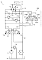
- FIG. 1 is a hydraulic circuit diagram of a hydraulic shovel according to an embodiment of the present invention, and shows a hydraulic circuit for driving a hydraulic motor for turning.
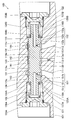
- FIG. 2 is a cross-sectional view of the check valve in the neutral position.
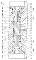
- FIG. 3 is a sectional view of the check valve in the second shut-off position.
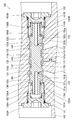
- FIG. 4 is a cross-sectional view of the check valve at the second communication position.
- FIG. 5 is a hydraulic circuit diagram of a hydraulic shovel according to a modification of the present embodiment, and shows a hydraulic circuit for driving a hydraulic motor for turning.
- the reversing prevention valve is a device for preventing a reversing operation immediately after an actuator such as a hydraulic motor stops.
- an actuator such as a hydraulic motor stops.
- a reversal prevention valve for preventing a reversal operation of a hydraulic motor which is an actuator used in a turning device of a hydraulic shovel, will be described.
- FIG. 1 is a hydraulic circuit diagram of a hydraulic shovel, showing a hydraulic circuit 10 for driving a hydraulic motor 12 for turning.
- the hydraulic circuit 10 is a hydraulic circuit in which a turning hydraulic pump 11 and a turning hydraulic motor 12 are connected by a direction control valve 13.
- the hydraulic circuit 10 includes a pair of main passages 17 a and 17 b for supplying and discharging hydraulic oil as a working fluid to and from the hydraulic motor 12, and a discharge passage 23 for discharging leak oil generated in a casing of the hydraulic motor 12 to a tank 19.
- a make-up passage 22 for supplying hydraulic oil to the main passages 17a and 17b through charge check valves 21a and 21b described later in order to suppress cavitation.
- the hydraulic circuit 10 includes a hydraulic pump 11 which is a fluid pressure supply source driven by an engine (not shown), a hydraulic motor 12 which is rotated by hydraulic oil discharged from the hydraulic pump 11 and drives the revolving unit 15 to pivot.
- a main relief valve 16 that regulates the maximum pressure of the hydraulic oil discharged from the hydraulic pump 11 and a tank 19 that stores the hydraulic oil are provided.
- the hydraulic circuit 10 is interposed between the directional control valve 13 for controlling the flow of hydraulic oil from the hydraulic pump 11 to the hydraulic motor 12 and the main passage 17a and the main passage 17b.
- Overload relief valves 18a and 18b for releasing hydraulic oil from the main passage on the side to the low-pressure main passage, and main passages 17a and 17b for supplying hydraulic oil to the main passages 17a and 17b under negative pressure.
- Charging check valves 21a and 21b interposed between the main passages 17a and 21b and allowing only the flow of hydraulic oil from the makeup passage 22 connected to the tank 19 to the negative passages 17a and 17b.
- Anti-reversal valve 100 interposed between the hydraulic motor 12 and the main passage 17b to prevent a reversal operation immediately after the hydraulic motor 12 stops.
- the direction control valve 13 is interposed in an oil passage between the hydraulic pump 11 and the hydraulic motor 12, and controls the flow of hydraulic oil from the hydraulic pump 11 to the hydraulic motor 12.
- the position of the spool of the direction control valve 13 is controlled by the operation pilot pressure input to the pilot pressure chambers 13a and 13b.
- the hydraulic motor 12 is connected to main passages 17a and 17b to which the hydraulic oil discharged from the hydraulic pump 11 through the direction control valve 13 is supplied.
- the torque of the hydraulic motor 12 is transmitted to the turning wheel 14 via a planetary reduction mechanism (not shown).
- the pilot pressure acts on the pilot pressure chamber 13a of the directional control valve 13, and the directional control valve 13 switches to the right turning position (A).
- the main passage 17 a is connected to the hydraulic pump 11, and the main passage 17 b is connected to the tank 19.
- the hydraulic oil discharged from the hydraulic pump 11 is supplied to the hydraulic motor 12 through the main passage 17a, the hydraulic oil is discharged from the hydraulic motor 12 to the tank 19 through the main passage 17b, and the hydraulic motor 12 rotates in one direction. (Forward rotation).
- the hydraulic motor 12 is driven to rotate forward, the swing body 15 swings rightward.
- the pilot pressure acts on the pilot pressure chamber 13b of the directional control valve 13, and the directional control valve 13 switches to the left turning position (B).
- the main passage 17 b is connected to the hydraulic pump 11, and the main passage 17 a is connected to the tank 19.
- the hydraulic oil discharged from the hydraulic pump 11 is supplied to the hydraulic motor 12 through the main passage 17b, the hydraulic oil is discharged from the hydraulic motor 12 to the tank 19 through the main passage 17a, and the hydraulic motor 12 rotates in the other direction. (Reverse).
- the swing body 15 swings leftward.
- Hydraulic oil in the main passage 17a or 17b on the discharge side of the hydraulic motor 12 is relieved by the overload relief valves 18a and 18b to the main passage 17b or 17a on the suction side of the hydraulic motor 12, so that inertia energy is consumed. Then, the revolving unit 15 decelerates and stops.
- the hydraulic motor 12 is stopped by the brake pressure, but one of the main passages 17a or 17b in which the brake pressure is generated maintains a high pressure state, and a differential pressure is generated between the other main passage 17b or 17a. For this reason, the hydraulic motor 12 performs a reversing operation of rotating in a direction opposite to the rotation direction before stopping, and thereafter, the same reversing operation is repeated. Therefore, in the present embodiment, the anti-reverse valve 100 is provided in order to converge the reversal operation performed repeatedly in a short time.
- the reversal prevention valve 100 prevents the revolving unit 15 from repeatedly performing the reversing operation by releasing the reversing pressure generated in the main passages 17a and 17b by starting the reversing operation of the revolving unit 15 to the tank 19.
- the check valve 100 includes a neutral position (N0), a first communication position (C1), a second communication position (C2), a first shutoff position (I1), and a second shutoff position ( I2).
- FIG. 2 is a cross-sectional view of the check valve 100 in the neutral position (N0).
- FIG. 3 is a cross-sectional view of the check valve 100 at the second shut-off position (I2)
- FIG. 4 is a cross-sectional view of the check valve 100 at the second communication position (C2). Note that the check valve 100 according to the present embodiment has a symmetrical shape.
- the check valve 100 includes a valve housing 101 in which a first supply / discharge passage 111, a second supply / discharge passage 112, and a part of a drain passage 113, which will be described later, are formed.
- a spool 102 movably accommodated, first and second biasing springs 104A and 104B as biasing members for biasing the spool 102 by elastic force, and hydraulic pressure for biasing the spool 102 are guided.
- a first pressure chamber 121 and a second pressure chamber 122 are provided.
- the first supply / discharge passage 111 is connected to one main passage 17 a of a pair of main passages 17 a and 17 b for supplying and discharging hydraulic oil to and from the hydraulic motor 12.
- the second supply / discharge passage 112 is connected to the other main passage 17b of the pair of main passages 17a, 17b.
- the drain passage 113 is connected to the makeup passage 22 and the discharge passage 23.
- the spool 102 is slidably received in a receiving hole 115 provided in the valve housing 101.
- the accommodation hole 115 is provided through the valve housing 101.
- the housing hole 115 has one open end closed by the first plug 103A and the other open end closed by the second plug 103B.
- the spool 102 is a shaft-shaped member, and is movable in a central axis direction (hereinafter, also simply referred to as an axial direction).
- the spool 102 moves to the neutral position (N0), the first blocking position (I1), the second blocking position (I2), the first communication position (C1), and the second communication position (I2) in the accommodation hole 115. , Is movable.
- a first pressure chamber 121 is provided on one side of the spool 102 in the axial direction.
- the first pressure chamber 121 is defined by the first plug 103A, the inner peripheral surface of the housing hole 115, and one end (left end in the drawing) of the spool 102 in the axial direction.
- hydraulic oil for urging the spool 102 in the other axial direction (to the right in the drawing) toward the second communication position (I2) is guided.
- a second pressure chamber 122 is provided in the other axial direction of the spool 102.
- the second pressure chamber 122 is defined by the second plug 103B, the inner peripheral surface of the housing hole 115, and the other axial end (the right end in the drawing) of the spool 102. Hydraulic oil that urges the spool 102 in one axial direction (leftward in the drawing) toward the first communication position (I1) is guided to the second pressure chamber 122.
- the pair of biasing springs 104A and 104B are coil springs that hold the spool 102 at the neutral position (N0), and expand and contract with the axial movement of the spool 102 to increase or decrease the biasing force on the spool 102.
- the first biasing spring 104A is disposed in a compressed state in the first pressure chamber 121, and biases the spool 102 in the same direction as the direction in which the spool 102 is biased by the hydraulic pressure of the first pressure chamber 121, that is, in the other axial direction. Energize.
- the second biasing spring 104B is disposed in a compressed state in the second pressure chamber 122, and biases the spool 102 in the same direction as the direction in which the spool 102 is biased by the hydraulic pressure of the second pressure chamber 122, that is, in one axial direction. I do.
- the spool 102 has a main body 130 and protruding ends 136A and 136B that protrude axially from both ends of the main body 130.
- the main body 130 includes a central land 133 provided at the axial center of the spool 102, an outer first land 134 provided at one axial end (left end in the drawing) of the spool 102, An outer second land portion 135 provided at an end portion (right end portion in the figure), an inner first land portion 131 provided between the outer first land portion 134 and the central land portion 133, and an outer second land portion 135 are provided.
- an inner second land 132 provided between the central land 133 and the center land 133.
- Each of the lands 131, 132, 133, 134, and 135 has a circular cross section centered on the central axis of the spool 102.
- a plurality of annular grooves 141, 142, 143 and 144 are provided on the outer periphery of the spool 102 so as to be depressed inward in the radial direction.
- An inner first annular groove 141 as a first annular groove is provided between the central land portion 133 and the inner first land portion 131, and between the central land portion 133 and the inner second land portion 132
- An inner second annular groove 142 as a second annular groove is provided.
- An outer first annular groove 143 is provided between the inner first land portion 131 and the outer first land portion 134, and an outer first annular groove 143 is provided between the inner second land portion 132 and the outer second land portion 135.
- Two annular grooves 144 are provided.
- the first supply / discharge passage 111, the drain passage 113, and the second supply / discharge passage 112 are provided in this order from one end (the left end in the drawing) of the housing hole 115 to the other end (the right end in the drawing).
- the outer first land portion 134 slides along the inner peripheral surface of the outer first sliding portion 115c between the first pressure chamber 121 and the first supply / discharge passage 111 in the housing hole 115.
- the inner first land portion 131 slides along the inner peripheral surface of the inner first sliding portion 115 a in the accommodation hole 115 between the first supply / discharge passage 111 and the drain passage 113.
- the inner second land portion 132 slides along the inner peripheral surface of the inner second sliding portion 115b between the drain passage 113 and the second supply / discharge passage 112 in the accommodation hole 115.
- the outer second land portion 135 slides along the inner peripheral surface of the outer second sliding portion 115d between the second supply / discharge passage 112 and the second pressure chamber 122 in the housing hole 115.
- the center land portion 133 slides along the inner peripheral surfaces of the inner first sliding portion 115a and the inner second sliding portion 115b.
- Each of the sliding portions 115a, 115b, 115c, and 115d has a circular cross section centered on the central axis of the spool 102.
- the protruding end 136A abuts on the first plug 103A and regulates the maximum movement amount (maximum stroke) of the spool 102 in one axial direction (left side in the figure).
- the protruding end 136B abuts on the second plug 103B, and regulates the maximum movement amount (maximum stroke) of the spool 102 in the other axial direction (rightward in the figure) (see FIG. 3).
- the first pressure chamber 121 has a circular cross section and an inner diameter larger than the inner diameter of the outer first sliding portion 115c. Therefore, a step portion 116A is formed between the inner peripheral surface of the first pressure chamber 121 and the inner peripheral surface of the outer first sliding portion 115c.
- the step portion 116A provided in the valve housing 101 functions as a first contact portion with which a first spring receiving member 125A described later contacts.
- the second pressure chamber 122 has a circular cross section, and has an inner diameter larger than the inner diameter of the outer second sliding portion 115d. Therefore, a step 116B is formed between the inner peripheral surface of the second pressure chamber 122 and the inner peripheral surface of the outer second sliding portion 115d.
- the step portion 116B provided in the valve housing 101 functions as a second contact portion with which a second spring receiving member 125B described later contacts.
- a step 137A is formed between the outer peripheral surface of the protruding end 136A and the outer peripheral surface of the outer first land portion 134.
- the outer diameter of the protruding end 136 ⁇ / b> B is smaller than the outer diameter of the outer second land 135. Therefore, a step 137B is formed between the outer peripheral surface of the protruding end portion 136B and the outer peripheral surface of the outer second land portion 135.
- the first biasing spring 104A is arranged so that the protruding end 136A is inserted inside.
- An annular first spring receiving member 125A is provided between a step portion 137A provided on one end side (left end side in the drawing) of the spool 102 and the first biasing spring 104A. Therefore, the first biasing spring 104A biases the spool 102 rightward in the figure via the first spring receiving member 125A.
- the second biasing spring 104B is arranged so that the protruding end 136B is inserted inside.
- An annular second spring receiving member 125B is provided between the step portion 137B provided on the other end side (the right end side in the figure) of the spool 102 and the second biasing spring 104B. Therefore, the second biasing spring 104B biases the spool 102 to the left in the drawing via the second spring receiving member 125B.
- the first communication passage 151 opens at the end face of the protruding end 136 ⁇ / b> A and opens at the axial passage 151 a extending in the axial direction of the spool 102 and at the bottom surface of the outer first annular groove 143. It has a radial passage 151b extending and a first throttle 151c interposed in the radial passage 151b. In other words, the first communication path 151 is provided with the first throttle 151c that imparts resistance to the passing hydraulic oil.
- the second communication passage 152 opens at the end surface of the protruding end 136B, opens at the axial passage 152a extending in the axial direction of the spool 102, and opens at the bottom surface of the outer second annular groove 144, and extends in the radial direction of the spool 102. It has a radial passage 152b extending and a second throttle 152c interposed in the radial passage 152b. In other words, the second communication passage 152 is provided with the second throttle 152c that imparts resistance to the hydraulic oil passing therethrough.
- the drain passage 113 is provided with a third restrictor 113a for giving resistance to the hydraulic oil passing therethrough.
- the spool 102 moves in the axial direction according to the pressure input to the first pressure chamber 121 and the second pressure chamber 122.
- the spool 102 is moved to the neutral position (N0) by the first biasing springs 104A and 104B as centering springs. Will be retained.
- the neutral position (N0) of the spool 102 is determined. The accuracy is improved.
- the spool 102 When the spool 102 is at the neutral position (N0), the hydraulic oil from the main passage 17a is guided to the first pressure chamber 121 via the first supply / discharge passage 111 and the first communication passage 151, and the first pressure chamber 121
- the spool 102 moves to the right in the figure as shown in FIG.
- the first spring receiving member 125A abuts on the step 116A and its movement is regulated, so that the first biasing spring 104A and the first spring receiving member 125A are separated from the step 137A of the spool 102.
- the second spring receiving member 125B is pressed by the step 137B of the spool 102, moves rightward in the figure, and separates from the step 116B of the valve housing 101. Therefore, the second biasing spring 104B contracts with the movement of the second spring receiving member 125B.
- the spool 102 when the spool 102 is at the neutral position (N0), the hydraulic oil from the main passage 17b is guided to the second pressure chamber 122 via the second supply / discharge passage 112 and the second communication passage 152, and When the pressure in the chamber 122 increases and becomes higher than the pressure in the first pressure chamber 121, the spool 102 moves to the left in the drawing. At this time, the second spring receiving member 125B abuts on the step portion 116B and its movement is regulated, so that the second biasing spring 104B and the second spring receiving member 125B are separated from the step portion 137B of the spool 102.
- the first spring receiving member 125A is pressed by the step 137A of the spool 102, moves to the left in the drawing, and separates from the step 116A of the valve housing 101. Therefore, the first biasing spring 104A contracts with the movement of the first spring receiving member 125A.
- the spool 102 when the spool 102 moves from the neutral position (N0) to the other axial direction (rightward in the drawing) by a predetermined stroke or more, the spool 102 is located at the second shut-off position (I2).
- the spool 102 When the spool 102 is located at the second blocking position (I2), the communication between the first supply / discharge passage 111 and the drain passage 113 is blocked by the inner first land portion 131. The communication between the second supply / discharge passage 112 and the drain passage 113 is blocked by the central land portion 133.
- the second supply / discharge passage 112 communicates with the drain passage 113 through the inner second annular groove 142.
- the communication between the first supply / discharge passage 111 and the drain passage 113 is blocked by the first inner land portion 131.
- the first supply / discharge passage 111 communicates with the drain passage 113 through the inner first annular groove 141.
- the communication between the second supply / discharge passage 112 and the drain passage 113 is blocked by the inner second land portion 132.
- the direction control valve 13 switches to the left turning position (B).
- hydraulic oil is supplied from the main passage 17b to the hydraulic motor 12, and hydraulic oil is discharged from the hydraulic motor 12 to the main passage 17a, so that the hydraulic motor 12 performs a left turning operation.
- the main passage 17b has a higher pressure than the main passage 17a.
- the check valve 100 switches from the neutral position (N0) to the first shut-off position (I1) when the pressure of the main passage 17b is guided to the second pressure chamber 122.
- the first shut-off position (I1) is a position where the spool 102 has moved from the neutral position (N0) in the axial direction by a predetermined stroke or more, for example, to the maximum, and in the first shut-off position (I1), the first supply / discharge passage.
- the communication between 111 and the drain passage 113 is cut off, and the communication between the second supply / discharge passage 112 and the drain passage 113 is cut off. Since the communication between the second supply / discharge passage 112 on the high pressure side and the drain passage 113 is cut off, when the hydraulic motor 12 is performing a left turning operation, the driving pressure for the hydraulic motor 12 is supplied to the tank 19 through the drain passage 113. Escape is prevented. Therefore, when accelerating or rotating the hydraulic motor 12 at a constant speed, it is possible to prevent the driving pressure for the hydraulic motor 12 from escaping through the reversal prevention valve 100, and to appropriately apply the driving force to the hydraulic motor 12. be able to.
- the direction control valve 13 switches to the neutral position (N), and the supply of the hydraulic oil from the hydraulic pump 11 to the hydraulic motor 12 is stopped. As a result, the revolving superstructure 15 is rotated by inertial force.
- ⁇ ⁇ ⁇ ⁇ Brake pressure is generated in the main passage 17a by the pumping action of the hydraulic motor 12, and the revolving unit 15 is decelerated.
- the main passage 17a has a higher pressure than the main passage 17b.
- the reversing prevention valve 100 switches from the first shut-off position (I1) to the second shut-off position (I2) when the pressure of the main passage 17a is led to the first pressure chamber 121.
- the spool 102 passes through the first communication position (C1) when moving from the first interruption position (I1) to the second interruption position (I2). Therefore, while the spool 102 moves from the first communication position (C1) to the neutral position (N0), the first supply / discharge passage 111 and the drain passage 113 communicate.
- the brake pressure will temporarily decrease sharply, and the braking operation of the revolving unit 15 will become unstable. There is a risk.
- the third throttle 113a is provided in the drain passage 113, a sharp decrease in brake pressure through the drain passage 113 is prevented, and the revolving unit 15 can be smoothly decelerated.
- the second shut-off position (I2) is a position where the spool 102 has moved from the neutral position (N0) to the other end in the axial direction by a predetermined stroke or more, for example, the maximum, and the second shut-off position (I2).
- the communication between the first supply / discharge passage 111 and the drain passage 113 is cut off, and the communication between the second supply / discharge passage 112 and the drain passage 113 is cut off. Since the communication between the first supply / discharge passage 111 on the high pressure side and the drain passage 113 is cut off, when the hydraulic motor 12 is stopped, brake pressure against the hydraulic motor 12 may escape to the tank 19 through the drain passage 113. Is prevented.
- the brake pressure on the hydraulic motor 12 can be prevented from escaping through the reversal prevention valve 100, and a braking force can be appropriately applied to the hydraulic motor 12.
- the hydraulic oil in the second supply / discharge passage 112 on the low pressure side is prevented from being guided to the hydraulic motor 12 through the check valve 100 and the discharge passage 23.
- it is possible to prevent the pressure exceeding the working pressure from acting on the seal member of the hydraulic motor 12 and prevent the seal member of the hydraulic motor 12 from being damaged, that is, the equipment on the discharge passage 23 from being damaged. can do.
- the hydraulic motor 12 is temporarily stopped by the brake pressure, the main passage 17a in which the brake pressure is generated is maintained in a high pressure state, so that the hydraulic motor 12 rotates rightward and the revolving unit 15 starts a rightward turning operation. .
- the reversing pressure is generated in the main passage 17b by the pumping action of the hydraulic motor 12 when the revolving unit 15 performs the right turning operation.
- the reversing pressure is guided to the second pressure chamber 122 of the reversing prevention valve 100.
- the reversing prevention valve 100 switches from the second shut-off position (I2) to the second communication position (C2).
- the second supply / discharge passage 112 and the drain passage 113 communicate with each other through the inner second annular groove 142, and the operating oil in the main passage 17b is supplied to the second supply / drain.
- the water is discharged to the tank 19 through the passage 112 and the drain passage 113. Since the reversal pressure generated in the main passage 17b is released through the reversal prevention valve 100, an increase in the reversal pressure is suppressed.
- the reversal prevention valve 100 is held at the second communication position (C2) for a predetermined time, and the rise of the reversal pressure generated in the main passage 17b can be effectively suppressed.
- the reversing prevention valve 100 includes a first communication position (C1) where the spool 102 communicates the first supply / discharge passage 111 with the drain passage 113 in the valve housing 101, and a second supply / discharge passage 112 with the drain passage. And a neutral position where communication between the first supply / discharge passage 111 and the drain passage 113 is cut off and communication between the second supply / discharge passage 112 and the drain passage 113 is cut off. (N0) is provided movably.
- the check valve 100 according to the present embodiment has a smaller number of components and a simple configuration as compared with the related art. Therefore, according to the present embodiment, it is possible to provide the anti-reversal valve 100 that prevents the reversing operation of the hydraulic motor 12 at low cost. Further, the check valve 100 according to the present embodiment does not need to be provided with a check valve in the valve housing 101, and thus there is no concern about malfunction of the check valve.
- the check valve 200 is configured such that when the spool 102 moves in the axial direction from the neutral position (N0) in one axial direction by a predetermined stroke or more, that is, when the spool 102 is at the first communication position (C1), the first The supply / discharge passage 111 is communicated with the drain passage 113.
- the reversing prevention valve 200 is turned on. And the drain passage 113 are communicated.
- the drain passage 113 is not connected to the discharge passage 23, but is connected only to the makeup passage 22. Accordingly, when a brake pressure is generated in one of the pair of main passages 17a, 17b, the hydraulic oil of the other of the pair of main passages 17a, 17b is connected to the discharge passage 23 through the check valve 200. Can be prevented. As a result, it is possible to prevent a pressure exceeding the working pressure from acting on the seal member of the hydraulic motor 12 and prevent the seal member of the hydraulic motor 12 from being damaged.
- the first shut-off position (I1) is the position where the spool 102 has moved to the maximum in the axial direction from the neutral position (N0)
- the second shut-off position (I2) is that the spool 102 is in the neutral position
- the valve housing 101 and the spool 102 move in the axial direction from the neutral position (N0) by a predetermined stroke or more, the communication between the first supply / discharge passage 111 and the drain passage 113 is cut off and the second supply / discharge passage 112 is opened. Any configuration may be used as long as communication with the drain passage 113 is interrupted.
- the predetermined stroke is not limited to the maximum stroke.
- the predetermined stroke is defined as an interrupting position (I2) when a pressure due to normal operation such as acceleration, constant rotation, and braking of the hydraulic motor 12 is guided to the first pressure chamber 121 (or the second pressure chamber 122). (Or a stroke that can be switched to the cutoff position (I1)), and may be a stroke shorter than the maximum stroke.
- the actuator for which the reversing operation is to be prevented is the hydraulic motor 12
- the present invention is not limited to this.
- the actuator may be a hydraulic cylinder that swings the swing body 15 left and right.
- the anti-reversing valves 100 and 200 are anti-reversing valves for preventing reversing operation immediately after the actuator (hydraulic motor 12) stops.
- a first supply / discharge passage 111 connected to one of the main passages 17a, 17b, a second supply / discharge passage 112 connected to the other of the pair of main passages 17a, 17b, and a drain passage 113 connected to the tank 19.
- a first communication position (C1) which is slidably accommodated in the valve housing 101 and communicates the first supply / discharge passage 111 and the drain passage 113, and a second supply / discharge passage 112.
- a first communication path 151 and a second communication path 152 that connects the second supply / discharge path 112 and the second pressure chamber 122 regardless of the position of the spool 102 are provided, and the first communication path 151 passes therethrough.
- Working fluid (actuated ) Is provided with a first restrictor 151c that provides resistance, and a second communication path 152 is provided with a second restrictor 152c that provides resistance to a working fluid (hydraulic oil) passing therethrough.
- first annular groove the inner first annular groove 141 that connects the first supply / discharge passage 111 and the drain passage 113 and the spool 102
- second annular groove inner second annular groove 142
- the reversal pressure when a reversing pressure is generated in the first supply / discharge passage 111, the reversal pressure can be released to the drain passage 113 through the first annular groove (the inner first annular groove 141).
- the reverse pressure when the reverse pressure is generated, the reverse pressure can be released to the drain passage 113 through the second annular groove 142 (the inner second annular groove 142). Since the reversing pressure can be released by the movement of the spool 102, the reversing prevention valves 100 and 200 that prevent the reversing operation of the actuator (the hydraulic motor 12) at low cost can be provided.
- the reversing prevention valve 100 shuts off the communication between the first supply / discharge passage 111 and the drain passage 113 and moves the second supply / discharge passage 112 when the valve housing 101 and the spool 102 move in the axial direction by a predetermined stroke or more. And the drain passage 113 are cut off from each other.
- the urging member is disposed in the first pressure chamber 121, and expands and contracts with the axial movement of the spool 102 to increase and decrease the urging force on the spool 102.
- a second biasing spring 104 ⁇ / b> B arranged in the second pressure chamber 122 and configured to expand and contract with the axial movement of the spool 102 to increase or decrease the biasing force on the spool 102.
- a second spring receiving member 125B provided between the other end of the spool 102 and the second urging spring 104B.
- the valve housing 101 includes a first contact portion (step portion 116A) with which the first spring receiving member 125A contacts, and a second contact portion (step portion 116B) with which the second spring receiving member 125B contacts.
Landscapes
- Engineering & Computer Science (AREA)
- General Engineering & Computer Science (AREA)
- Mechanical Engineering (AREA)
- Mining & Mineral Resources (AREA)
- Civil Engineering (AREA)
- Structural Engineering (AREA)
- Physics & Mathematics (AREA)
- Fluid Mechanics (AREA)
- Fluid-Pressure Circuits (AREA)
- Operation Control Of Excavators (AREA)
- Multiple-Way Valves (AREA)
Priority Applications (4)
| Application Number | Priority Date | Filing Date | Title |
|---|---|---|---|
| CN201980005452.XA CN111295522B (zh) | 2018-08-29 | 2019-07-03 | 防反转阀 |
| EP19854095.7A EP3680492B1 (en) | 2018-08-29 | 2019-07-03 | Reverse-rotation prevention valve |
| KR1020207009710A KR20200051703A (ko) | 2018-08-29 | 2019-07-03 | 반전 방지 밸브 |
| US16/757,163 US20200340210A1 (en) | 2018-08-29 | 2019-07-03 | Anti-reverse valve |
Applications Claiming Priority (2)
| Application Number | Priority Date | Filing Date | Title |
|---|---|---|---|
| JP2018160329A JP7033036B2 (ja) | 2018-08-29 | 2018-08-29 | 反転防止弁 |
| JP2018-160329 | 2018-08-29 |
Publications (1)
| Publication Number | Publication Date |
|---|---|
| WO2020044783A1 true WO2020044783A1 (ja) | 2020-03-05 |
Family
ID=69644136
Family Applications (1)
| Application Number | Title | Priority Date | Filing Date |
|---|---|---|---|
| PCT/JP2019/026504 Ceased WO2020044783A1 (ja) | 2018-08-29 | 2019-07-03 | 反転防止弁 |
Country Status (6)
| Country | Link |
|---|---|
| US (1) | US20200340210A1 (enExample) |
| EP (1) | EP3680492B1 (enExample) |
| JP (1) | JP7033036B2 (enExample) |
| KR (1) | KR20200051703A (enExample) |
| CN (1) | CN111295522B (enExample) |
| WO (1) | WO2020044783A1 (enExample) |
Families Citing this family (3)
| Publication number | Priority date | Publication date | Assignee | Title |
|---|---|---|---|---|
| US12085099B1 (en) * | 2020-06-18 | 2024-09-10 | Vacuworx Global, LLC | Flow control block for use with a vacuum material handler |
| KR102581960B1 (ko) * | 2021-07-28 | 2023-09-22 | 주식회사 모트롤 | 모터 |
| NL2037376B1 (en) * | 2024-03-11 | 2024-12-03 | Hangzhou Polytechnic | Crusher bucket control valve with internal oil replenishing valve |
Citations (3)
| Publication number | Priority date | Publication date | Assignee | Title |
|---|---|---|---|---|
| JPS5850369A (ja) * | 1981-09-21 | 1983-03-24 | Kawasaki Heavy Ind Ltd | 方向制御弁 |
| JPH07293509A (ja) * | 1994-04-27 | 1995-11-07 | Hitachi Constr Mach Co Ltd | 油圧モータのブレーキ制御装置 |
| JP2018160329A (ja) | 2017-03-22 | 2018-10-11 | 住友化学株式会社 | 有機el素子及び有機el素子の製造方法 |
Family Cites Families (7)
| Publication number | Priority date | Publication date | Assignee | Title |
|---|---|---|---|---|
| JP2511317B2 (ja) * | 1989-12-04 | 1996-06-26 | 日立建機株式会社 | 油圧モ―タ駆動回路 |
| EP0457913A4 (en) * | 1989-12-04 | 1993-03-31 | Hitachi Construction Machinery Co., Ltd. | Hydraulic motor driving circuit device |
| JP3068863B2 (ja) * | 1990-12-26 | 2000-07-24 | 株式会社不二越 | 反転防止弁 |
| JPH08166002A (ja) * | 1994-12-13 | 1996-06-25 | Komatsu Ltd | 流体ブレーキ装置 |
| US6539712B2 (en) * | 1999-12-27 | 2003-04-01 | Kayaba Kogyo Kabushiki Kaisha | Hydraulic drive unit |
| JP4216200B2 (ja) * | 2002-04-26 | 2009-01-28 | 日立建機株式会社 | 油圧駆動車両の走行制御装置、油圧駆動車両、およびホイール式油圧ショベル |
| GB2395989B (en) * | 2002-11-27 | 2007-02-07 | Komatsu Uk Ltd | Travel control apparatus of hydraulic travelling vehicle |
-
2018
- 2018-08-29 JP JP2018160329A patent/JP7033036B2/ja active Active
-
2019
- 2019-07-03 CN CN201980005452.XA patent/CN111295522B/zh active Active
- 2019-07-03 KR KR1020207009710A patent/KR20200051703A/ko not_active Ceased
- 2019-07-03 WO PCT/JP2019/026504 patent/WO2020044783A1/ja not_active Ceased
- 2019-07-03 EP EP19854095.7A patent/EP3680492B1/en active Active
- 2019-07-03 US US16/757,163 patent/US20200340210A1/en not_active Abandoned
Patent Citations (3)
| Publication number | Priority date | Publication date | Assignee | Title |
|---|---|---|---|---|
| JPS5850369A (ja) * | 1981-09-21 | 1983-03-24 | Kawasaki Heavy Ind Ltd | 方向制御弁 |
| JPH07293509A (ja) * | 1994-04-27 | 1995-11-07 | Hitachi Constr Mach Co Ltd | 油圧モータのブレーキ制御装置 |
| JP2018160329A (ja) | 2017-03-22 | 2018-10-11 | 住友化学株式会社 | 有機el素子及び有機el素子の製造方法 |
Non-Patent Citations (1)
| Title |
|---|
| See also references of EP3680492A4 |
Also Published As
| Publication number | Publication date |
|---|---|
| EP3680492B1 (en) | 2022-10-26 |
| CN111295522A (zh) | 2020-06-16 |
| KR20200051703A (ko) | 2020-05-13 |
| EP3680492A1 (en) | 2020-07-15 |
| JP2020034070A (ja) | 2020-03-05 |
| CN111295522B (zh) | 2022-04-29 |
| JP7033036B2 (ja) | 2022-03-09 |
| EP3680492A4 (en) | 2021-07-07 |
| US20200340210A1 (en) | 2020-10-29 |
Similar Documents
| Publication | Publication Date | Title |
|---|---|---|
| WO2020044783A1 (ja) | 反転防止弁 | |
| WO2015181935A1 (ja) | 弁装置 | |
| JP5348899B2 (ja) | ブレーキシステム | |
| JP4613057B2 (ja) | 液圧モータ | |
| JP2016169828A (ja) | 変速装置及びそれを備える発電システム | |
| WO2015141466A1 (ja) | ポンプ装置 | |
| JP6379120B2 (ja) | ミキサドラム駆動装置 | |
| JP5571809B2 (ja) | ブレーキシステム | |
| JP5464275B2 (ja) | 油圧モータ用制御装置 | |
| JPH05321906A (ja) | 慣性体反転防止弁 | |
| JP2009174575A (ja) | ブレーキ弁 | |
| WO2017110525A1 (ja) | ミキサドラム駆動装置 | |
| WO2019058711A1 (ja) | 液圧モータ制御装置 | |
| JP6928481B2 (ja) | 油圧供給機構及びオイルポンプ装置 | |
| JP4963639B2 (ja) | 油圧モータのブレーキシステム | |
| KR102166311B1 (ko) | 에너지 충전 및 재생용 방향제어밸브와, 이를 구비한 건설기계의 선회 에너지 재생 장치 | |
| JP2004204922A (ja) | 流体モータの駆動回路 | |
| WO2020195072A1 (ja) | 弁装置 | |
| WO2020070936A1 (ja) | ブレーキバルブ装置及びモータ装置 | |
| JPH1122843A (ja) | ブレーキ弁 | |
| JP3710005B2 (ja) | 油圧アクチュエータの反転防止装置 | |
| WO2025052916A1 (ja) | 流体圧制御装置 | |
| JPH07133803A (ja) | 揺戻り防止弁を有する液圧制御装置 | |
| JP5894808B2 (ja) | ミキサドラム駆動装置 | |
| JP2002206505A (ja) | 旋回用油圧回路 |
Legal Events
| Date | Code | Title | Description |
|---|---|---|---|
| ENP | Entry into the national phase |
Ref document number: 20207009710 Country of ref document: KR Kind code of ref document: A |
|
| 121 | Ep: the epo has been informed by wipo that ep was designated in this application |
Ref document number: 19854095 Country of ref document: EP Kind code of ref document: A1 |
|
| ENP | Entry into the national phase |
Ref document number: 2019854095 Country of ref document: EP Effective date: 20200409 |
|
| NENP | Non-entry into the national phase |
Ref country code: DE |