WO2020009034A1 - 車両用構造部材のための補強部材とその製造法 - Google Patents
車両用構造部材のための補強部材とその製造法 Download PDFInfo
- Publication number
- WO2020009034A1 WO2020009034A1 PCT/JP2019/025876 JP2019025876W WO2020009034A1 WO 2020009034 A1 WO2020009034 A1 WO 2020009034A1 JP 2019025876 W JP2019025876 W JP 2019025876W WO 2020009034 A1 WO2020009034 A1 WO 2020009034A1
- Authority
- WO
- WIPO (PCT)
- Prior art keywords
- vehicle
- reinforcing member
- vertical wall
- press
- hinge reinforcement
- Prior art date
Links
Images


Classifications
-
- B—PERFORMING OPERATIONS; TRANSPORTING
- B62—LAND VEHICLES FOR TRAVELLING OTHERWISE THAN ON RAILS
- B62D—MOTOR VEHICLES; TRAILERS
- B62D25/00—Superstructure or monocoque structure sub-units; Parts or details thereof not otherwise provided for
- B62D25/04—Door pillars ; windshield pillars
-
- B—PERFORMING OPERATIONS; TRANSPORTING
- B21—MECHANICAL METAL-WORKING WITHOUT ESSENTIALLY REMOVING MATERIAL; PUNCHING METAL
- B21D—WORKING OR PROCESSING OF SHEET METAL OR METAL TUBES, RODS OR PROFILES WITHOUT ESSENTIALLY REMOVING MATERIAL; PUNCHING METAL
- B21D22/00—Shaping without cutting, by stamping, spinning, or deep-drawing
- B21D22/20—Deep-drawing
- B21D22/26—Deep-drawing for making peculiarly, e.g. irregularly, shaped articles
-
- B—PERFORMING OPERATIONS; TRANSPORTING
- B21—MECHANICAL METAL-WORKING WITHOUT ESSENTIALLY REMOVING MATERIAL; PUNCHING METAL
- B21D—WORKING OR PROCESSING OF SHEET METAL OR METAL TUBES, RODS OR PROFILES WITHOUT ESSENTIALLY REMOVING MATERIAL; PUNCHING METAL
- B21D53/00—Making other particular articles
- B21D53/88—Making other particular articles other parts for vehicles, e.g. cowlings, mudguards
-
- B—PERFORMING OPERATIONS; TRANSPORTING
- B23—MACHINE TOOLS; METAL-WORKING NOT OTHERWISE PROVIDED FOR
- B23K—SOLDERING OR UNSOLDERING; WELDING; CLADDING OR PLATING BY SOLDERING OR WELDING; CUTTING BY APPLYING HEAT LOCALLY, e.g. FLAME CUTTING; WORKING BY LASER BEAM
- B23K11/00—Resistance welding; Severing by resistance heating
- B23K11/10—Spot welding; Stitch welding
- B23K11/11—Spot welding
-
- B—PERFORMING OPERATIONS; TRANSPORTING
- B23—MACHINE TOOLS; METAL-WORKING NOT OTHERWISE PROVIDED FOR
- B23K—SOLDERING OR UNSOLDERING; WELDING; CLADDING OR PLATING BY SOLDERING OR WELDING; CUTTING BY APPLYING HEAT LOCALLY, e.g. FLAME CUTTING; WORKING BY LASER BEAM
- B23K26/00—Working by laser beam, e.g. welding, cutting or boring
- B23K26/20—Bonding
- B23K26/21—Bonding by welding
- B23K26/22—Spot welding
-
- B—PERFORMING OPERATIONS; TRANSPORTING
- B23—MACHINE TOOLS; METAL-WORKING NOT OTHERWISE PROVIDED FOR
- B23K—SOLDERING OR UNSOLDERING; WELDING; CLADDING OR PLATING BY SOLDERING OR WELDING; CUTTING BY APPLYING HEAT LOCALLY, e.g. FLAME CUTTING; WORKING BY LASER BEAM
- B23K31/00—Processes relevant to this subclass, specially adapted for particular articles or purposes, but not covered by only one of the preceding main groups
- B23K31/12—Processes relevant to this subclass, specially adapted for particular articles or purposes, but not covered by only one of the preceding main groups relating to investigating the properties, e.g. the weldability, of materials
- B23K31/125—Weld quality monitoring
-
- B—PERFORMING OPERATIONS; TRANSPORTING
- B23—MACHINE TOOLS; METAL-WORKING NOT OTHERWISE PROVIDED FOR
- B23K—SOLDERING OR UNSOLDERING; WELDING; CLADDING OR PLATING BY SOLDERING OR WELDING; CUTTING BY APPLYING HEAT LOCALLY, e.g. FLAME CUTTING; WORKING BY LASER BEAM
- B23K33/00—Specially-profiled edge portions of workpieces for making soldering or welding connections; Filling the seams formed thereby
- B23K33/002—Crimping or bending the workpieces at the joining area
-
- B—PERFORMING OPERATIONS; TRANSPORTING
- B23—MACHINE TOOLS; METAL-WORKING NOT OTHERWISE PROVIDED FOR
- B23K—SOLDERING OR UNSOLDERING; WELDING; CLADDING OR PLATING BY SOLDERING OR WELDING; CUTTING BY APPLYING HEAT LOCALLY, e.g. FLAME CUTTING; WORKING BY LASER BEAM
- B23K2101/00—Articles made by soldering, welding or cutting
- B23K2101/006—Vehicles
-
- B—PERFORMING OPERATIONS; TRANSPORTING
- B23—MACHINE TOOLS; METAL-WORKING NOT OTHERWISE PROVIDED FOR
- B23K—SOLDERING OR UNSOLDERING; WELDING; CLADDING OR PLATING BY SOLDERING OR WELDING; CUTTING BY APPLYING HEAT LOCALLY, e.g. FLAME CUTTING; WORKING BY LASER BEAM
- B23K2103/00—Materials to be soldered, welded or cut
- B23K2103/02—Iron or ferrous alloys
- B23K2103/04—Steel or steel alloys
Definitions
- the present invention relates to a reinforcing member for a structural member for a vehicle and a method of manufacturing the reinforcing member.
- pillars are provided on the side of vehicles such as automobiles as vehicle structural members.
- the pillars include a front pillar generally called an A pillar, a center pillar commonly called a B pillar, and a rear pillar commonly called a C pillar from the front of the automobile.
- the center pillar is particularly required to have structural strength in order to cope with a side collision (side collision) of an automobile. Therefore, the center pillar is provided with a reinforcing member called a hinge reinforcement to reinforce its strength.
- a mounting portion for mounting other surrounding vehicle components may be provided on the pillar. Therefore, the pillar also needs strength for that purpose.
- a striker that locks a door (door) installed on a side portion of the vehicle in a closed state is disposed on the center pillar.
- a flat portion for attaching the striker is formed on the hinge reinforcement, which is a reinforcing member of the center pillar.
- the center pillar is formed in a closed cross section by an outer panel having a long hat-shaped cross section and a flat inner panel.
- a hinge reinforcement is provided in the closed section, and is joined to the outer panel by welding or the like to reinforce the center pillar.
- the hinge reinforcement Since the hinge reinforcement is disposed within the closed cross section of the center pillar, the hinge reinforcement has a U-shaped cross section corresponding to the inner surface shape of the outer panel having a hat-shaped cross section, and is formed in an elongated shape.
- the U-shaped cross-section is formed by a top plate in the center in the width direction (vehicle front-rear direction) and a pair of vertical wall portions that are bent and extended from ridge lines at both ends in the width direction of the top plate. Is done.
- a plane portion for attaching a striker which is another component described above, is formed in a vertical wall portion.
- the hinge reinforcement is formed by pressing.
- One steel plate is bent by press molding to form a U-shaped cross section (see JP-A-2013-220807).
- press forming a press forming die for drawing and a press forming die for bending are usually used.
- the material of the hinge reinforcement tends to increase the strength of the material due to the recent demand for the improvement of the side collision performance.
- a high-strength material is used in press molding, it is difficult to crush and flatten a wrinkle (wrinkle) on the molding once generated in the press molding process. That is, when the material strength is not high, even if wrinkles are formed during the forming process, the wrinkles can be crushed at the last press forming of the forming to form a planar shape.
- a high-strength material it is considered that once a wrinkle is formed, it is difficult to break the wrinkle in a subsequent press molding process because of the high strength.
- One aspect of the present invention is a reinforcing member for a structural member for a vehicle, comprising: a top plate portion; and a pair of vertical wall portions extending from both ends of the top plate portion.
- a flat portion for mounting another vehicle component is formed on at least one of the vertical wall portions of the portion, and the flat portion has an edge on the front side in the pressing direction when the reinforcing member is press-formed in the pressing direction. It has a convex curved shape.
- the vehicle structural member is a pillar installed on a side of the vehicle, and the reinforcing member is a hinge reinforcement for reinforcing the pillar.
- the other vehicle component is a striker for locking a vehicle door, and the striker is attached to the plane portion.
- Another aspect of the present invention is a method of manufacturing a reinforcing member for a structural member for a vehicle, comprising a step of press-forming the reinforcing member by a press mold, wherein the press mold includes the vertical wall portion.
- the step of press forming includes a step of drawing the reinforcing member by a drawing die and a step of bending the drawn reinforcing member by a bending die. And each of the bending molds has a first die face having the convex curved shape.
- the mounting flat portion may be pressed during the press forming. It is possible to prevent or suppress the generation of wrinkles of undulation.
- FIG. 1 is an overall view showing an example of a center pillar arranged on a side portion of a vehicle such as an automobile.
- FIG. 2 is a cross-sectional view of the center pillar of FIG. 1 taken along the line II-II. It is the front view which looked at the top board part of the hinge reinforcement after the 2nd process (final form) from the vehicle outside.
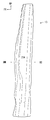
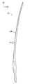
- FIG. 4 is a side view showing a vertical wall portion on a vehicle rear side when the hinge reinforcement shown in FIG. 3 is viewed from a direction of an arrow IV.
- FIG. 5 is a side view showing a vertical wall portion on a vehicle front side when the hinge reinforcement shown in FIG. 3 is viewed from a direction of an arrow V.
- FIG. 1 is an overall view showing an example of a center pillar arranged on a side portion of a vehicle such as an automobile.
- FIG. 2 is a cross-sectional view of the center pillar of FIG. 1 taken along the line II-II. It is the front view which looked at
- FIG. 6 is an enlarged view showing a plane portion for mounting a striker in the hinge reinforcement indicated by a circle VI in FIG. 5 in an enlarged manner. It is a perspective view which expands and shows the welding protrusion part formed in the vertical wall part of a hinge reinforcement. It is a key map showing the schematic structure of the draw forming process of hinge reinforcement. It is a conceptual diagram showing the schematic structure of the bending process of hinge reinforcement. It is sectional drawing which shows the state which attached the striker to the center pillar. It is the front view which looked at the top board part of the hinge reinforcement after the 1st process (after the drawing forming process) from the vehicle outside.
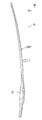
- FIG. 12 is a side view showing the vertical wall portion on the vehicle rear side when the hinge reinforcement shown in FIG. 11 is viewed from the direction of arrow XII.
- FIG. 13 is a side view showing the vertical wall portion on the vehicle front side when the hinge reinforcement shown in FIG. 11 is viewed from the direction of arrow XIII.
- the vehicle structural member is a center pillar, which is one of pillars installed on a side of a vehicle such as an automobile, and the reinforcing member is a hinge reinforcement for reinforcing the center pillar.
- the term regarding the direction used in the following description basically refers to a direction based on the vehicle in a normal posture.
- the arrow FR indicates the vehicle forward direction
- the arrow UP indicates the vehicle upward direction
- the arrow IN indicates the vehicle inside direction.
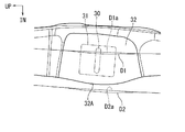
- FIG. 1 shows the appearance of a center pillar 10 for a vehicle such as an automobile
- FIG. 2 shows a cross section of the center pillar 10 of FIG. 1 taken along the line II-II.
- the center pillar 10 in FIG. 1 is on the left side of the vehicle.
- a front pillar (not shown) and a rear pillar (not shown) are arranged on the side of the vehicle as structural members for the vehicle.
- the strength of the center pillar 10 is particularly emphasized in view of a request for a side collision (side collision) of an automobile. Therefore, as shown in FIG. 2, a hinge reinforcement 20 is provided as a reinforcing member on the center pillar 10 to reinforce its strength.
- a high-strength steel plate is used as described later in response to a recent demand for higher strength.
- the center pillar 10 includes a long outer panel 12 that forms the outside of the vehicle and a long inner panel 14 that forms the inside of the vehicle.
- the center pillar 10 further includes a hinge reinforcement 20 disposed inside the outer panel 12.
- the outer panel 12 has a hat-shaped cross section that opens inward of the vehicle, and includes a top plate portion 12A, a vertical wall portion 12B, and a flange portion 12C.
- the top plate portion 12A is disposed on the outer side of the vehicle (lower side in FIG. 2), and a pair of left and right vertical wall portions 12B extend inward (upper side in FIG. 2) from both ends thereof.
- the pair of left and right vertical wall portions 12B are inclined in such a direction as to increase the space inward (upward in FIG. 2).
- the flange portions 12C extend in opposite directions from the inner (upper side in FIG. 2) ends of the pair of vertical wall portions 12B. Note that the flange portion 12C extends in the same direction as the top plate portion 12A.
- first vertical wall portion 12B and the first flange portion 12C which are arranged symmetrically, they are arranged on the vehicle rear side (right side) as viewed in FIG.
- members having the same reference numerals as those of the corresponding members and members provided on the front side (left side) of the vehicle are indicated with an f.
- the inner panel 14 is formed in a substantially flat plate shape, and a flange portion 14C extends outwardly from both side edges (right and left ends in FIG. 2) on the front and rear sides of the vehicle. Is out.
- the two flange portions 14C of the inner panel 14 are overlapped with the two flange portions 12C of the outer panel 12 in the vehicle width direction and joined by spot welding to form a closed cross section.
- welding points are indicated by black circles and in FIG. 2 by crosses. Further, the welding is not limited to spot welding, and may be performed by another method such as laser welding.
- the center pillar 10 is arranged to extend vertically in the vehicle.
- the center pillar 10 has a gently curved shape in which a central portion in the long direction protrudes outwardly.
- the center pillar 10 is inclined such that the upper end is located rearward of the vehicle from the lower end.
- the elongated center pillar 10 is formed in a closed cross-sectional structure, and forms one internal space inside.
- the center pillar 10 is joined to a roof side rail 18 via a substantially T-shaped mounting portion 16 formed at the upper end of the outer panel 12.
- the center pillar 10 is joined to the side sill 19 via a substantially T-shaped mounting portion 17 formed at the lower end of the outer panel 12.
- the outer panel 12 is a steel plate member having a tensile strength of 1180 MPa or more. In one embodiment, a 1470 MPa high tensile steel plate is used.
- the outer panel 12 is formed by a room temperature press, a cold press, or a hot stamp.
- the hinge reinforcement 20 arranged in the inner space of the center pillar 10 will be described. As shown in FIG. 2, the hinge reinforcement 20 is provided along the inner surface of the outer panel 12 of the center pillar 10.
- the hinge reinforcement 20 includes a top plate 20A and a vertical wall 20B.
- the hinge reinforcement 20 Since the hinge reinforcement 20 is disposed along the inner surface of the outer panel 12 of the center pillar 10 as described above, the hinge reinforcement 20 has a substantially U-shaped cross section.
- the top panel 20A is arranged inside the top panel 12A of the outer panel 12.
- the left and right vertical wall portions 20B as viewed in FIG. 2 are disposed inside the vertical wall portion 12B of the outer panel 12, and are directed inward (upward as viewed in FIG. 2) from the ridge lines L1 at both ends of the top plate portion 20A. It is formed integrally connected.
- the left and right vertical wall portions 20B are inclined in such a direction as to increase the interval inward (upward in FIG. 2).
- the vehicle rear side (the right side in FIG. 2).
- the members that are disposed at the front of the vehicle are denoted by the letter r
- the members that are disposed at the front side of the vehicle are denoted by the letter f.
- a front and rear door (not shown) of the vehicle is arranged before and after the center pillar 10 shown in FIG.
- a front door (front door) is arranged at the front of the center pillar 10
- a rear door (rear door) is arranged at the rear.
- the front door is opened and closed by a door hinge installed on the front pillar, and the front door is locked to the center pillar 10 by a striker 30 attached to the center pillar 10.
- the striker 30 is disposed below the front side of the center pillar 10 as shown in FIG.
- the striker 30 is illustrated as an image of the position of the striker 30 disposed on the vertical wall portions 12Bf and 20Bf on the front side. 2 is indicated by a two-dot chain line.
- FIG. 10 shows a specific configuration in which the striker 30 is disposed on the center pillar 10.
- the thickness of the outer panel 12, the inner panel 14, and the hinge reinforcement 20 is omitted.
- the striker 30 is disposed on the outer panel 12 and the vertical wall portions 12Bf, 20Bf on the front side of the hinge reinforcement 20.
- the striker mounting seat 31 is fixed and attached to the vertical wall portions 12Bf, 20Bf by fastening means 36 such as a bolt and a nut.
- the decorative plate 38 is provided outside the outer panel 12.
- FIGS. 3 to 5 show the overall structure of the hinge reinforcement 20.
- FIG. 3 is a view of the top plate portion 20A of the hinge reinforcement 20 as viewed from the outside.
- FIG. 4 shows a vertical wall portion 20Br on the vehicle rear side when the hinge reinforcement 20 of FIG. 3 is viewed from the direction of arrow IV.
- FIG. 5 shows the vertical wall portion 20Bf on the vehicle front side when the hinge reinforcement 20 shown in FIG. 3 is viewed from the direction of arrow V.
- the hinge reinforcement 20 is formed in a long shape, and is formed in a shape that is gently curved outward and convex as shown in FIGS. 4 and 5. I have.
- the hinge reinforcement 20 is formed by pressing. Then, in order to enhance the side collision performance, a high-tensile steel plate is used as a material for press forming. Its tensile strength is 980 MPa or more. In one embodiment, a high-strength steel plate of 1180 MPa is used. The thickness of the steel sheet is, for example, about 1 mm to 2 mm, and one high-tensile steel sheet is press-formed by a room temperature press, a cold press, or a hot stamp.
- the top plate 20A of the hinge reinforcement 20 is welded to the inner surface of the top plate 12A of the outer panel 12 of the center pillar 10 by spot welding. Is done. For this reason, a welding projection 22 for forming a welding seat surface 23 projects from the top plate 20A to the outside of the vehicle by a predetermined height.
- the welding protruding portions 22 are intermittently arranged along the vertical direction of the vehicle.
- the outer surface of the projection 22 for welding is formed in a flat shape as shown in FIG. 2 in order to secure the bonding strength between the outer panel 12 and the top plate 12A by spot welding.
- the shape of each of the welding protrusions 22 can be formed in a semicircle or a circle as one embodiment. However, as another embodiment, various shapes such as a rectangle, a triangle, an ellipse, and a hexagon can be used. You can also.
- the welding between the center pillar 10 and the hinge reinforcement 20 is also performed between the vertical wall portion 12B of the outer panel 12 and the vertical wall portion 20B of the hinge reinforcement 20, at the locations indicated by the crosses in FIG. ing. Therefore, a pair of vertical wall portions 20Br and 20Bf of the hinge reinforcement 20 shown in FIGS. 4 and 5 are provided with a welding projection 25 for forming a welding seat surface 26. However, in the pair of vertical wall portions 20Br and 20Bf shown in FIGS. 4 and 5, the welding protruding portion 25 is omitted.
- the welding projection 25 is formed so as to project toward the pair of vertical walls 12B of the outer panel 12, and is intermittently arranged in the vehicle vertical direction. And it is joined by spot welding to the inner surface of the vertical wall portion 12B at the welding seat surface 26 on the surface of the welding projection 25.
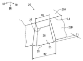
- FIG. 7 schematically shows the welding protrusion 25 formed on the vertical wall portion 20B of the hinge reinforcement 20.
- Each of the welding protrusions 25 projects from the vertical wall portion 20B to the outside of the hinge reinforcement 20 by a predetermined height T1.
- each welding protrusion 25 extends from each ridge line L1 formed between the pair of vertical wall portions 20B and the top plate portion 20A to the vehicle inner side of the vertical wall portion 20B. Project over the entire width up to the edge of the hinge reinforcement 20.
- Each of the welding protrusions 25 is formed in a trapezoidal shape in which the width W1 at the edge on the ridge line L1 side is smaller than the width W2 at the edge on the vehicle inward side, as viewed from the front.
- the edge of each welding protrusion 25 on the ridge line L1 side is chamfered diagonally toward the ridge line L1.
- each welding projection 25 that is, the welding seating surface 26 secures the bonding strength between the outer panel 12 and each vertical wall portion 12 ⁇ / b> B by spot welding. It is formed in a planar shape. Therefore, each welding seat surface 26 is flat from the edge 27 on each ridge line L1 side to the edge on the vehicle inward side of the vertical wall portion 20B, and the length of the edge 27 on the ridge line L1 side is long. It is formed in a trapezoidal shape that is narrower than the length of the edge 28 on the inner side of the vehicle and is turned sideways as viewed from the front.
- a flat surface portion 32 for attaching the striker 30 for locking the front door in a closed position is provided at a lower portion. Part is formed.
- the hatched portion in FIG. 5 is the plane portion 32 for mounting the striker.
- FIG. 6 shows the same portion in an enlarged manner. In FIG. 6, the position where the striker 30 is provided is indicated by a two-dot chain line.
- the striker 30 is attached to the outer panel 12 and the vertical wall portions 12B and 20B of the hinge reinforcement 20 via a striker mounting seat 31 having a flat plate shape to which the striker 30 is fixed. Therefore, it is required that the striker mounting flat portion 32 be formed in a flat shape without wrinkles.
- the flat portion 32 shown in FIG. 6 has a convex shape in which an edge 32A on the vehicle inward side projects toward the vehicle inward (downward in FIG. 6) by press molding.
- This convex shape is, for example, a smooth and gentle curved shape.
- the flat portion 32 is formed by press forming the hinge reinforcement 20.
- FIGS. 8 and 9 show the arrangement of the forming dies in the draw forming step
- FIG. 9 shows the arrangement of the forming dies for performing the bending forming step.
- Each is for explaining press forming of the plane portion 32 in a cross section taken along line VII-VII in FIG.
- the pressing direction in the hinge reinforcement 20 is indicated by a white arrow P in FIGS. 4 and 5.
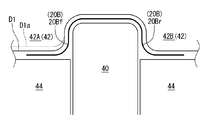
- FIG. 8 shows the draw forming step of the first step.
- the drawing die includes a fixed lower die 40, a movable upper die 42, and cushion dies 44 arranged on both sides of the lower die 40.
- the upper die 42 is integrally provided with a portion 42A for drawing and forming the front vertical wall portion 20Bf and a portion 42B for drawing and forming the rear vertical wall portion 20Br.
- the cushion mold 44 follows the movement of the upper mold 42 for drawing.
- the portion where the striker mounting flat portion 32 is formed corresponds to the above-described edge 32A on the front side in the pressing direction of the flat portion 32 described above. It has a convex shape.
- the vertical wall portion 20Bf has a smooth and gentle curved shape that swells forward in the pressing direction with respect to the die face that forms the portion adjacent to the flat portion 32 in the pressing direction.
- the dashed line D1a indicates the die face shape of the flat portion 32 that is not a normal convex shape.
- FIG. 8 also shows a normal die face position by a broken line. The fact that the die face has a convex shape means that the drawing depth at the flat portion 32 is deeper than the periphery.
- FIG. 9 shows the bending process of the second process.
- the bending mold includes a fixed lower mold 50, a movable upper mold 52, and a pad 54 for holding a press-formed product.
- the upper die 52 has an upper die 52A that bends the vertical wall 20Bf and an upper die 52B that bends the vertical wall 20Br.
- the pad 54 is for fixing the work (work) drawn and formed in the first step on the lower die 50, and performs bending while holding the work by the pad 54.
- the die face shape of the upper die 52A for bending and forming the vertical wall portion 20Bf is set to the same shape as the die face shape of the portion 42A for forming the vertical wall portion 20Bf of the upper die 42 in the above-described drawing. That is, the die face shape of the upper mold 52A is set to the shape shown by the solid line D2 in FIGS. Also in the bending in the second step, the die face of the upper die 52A for forming the plane portion 32 for attaching the striker has a convex shape corresponding to the edge 32A of the plane portion 32 on the front side in the pressing direction.
- the vertical wall portion 20Bf has a smooth and gentle curved shape that swells forward in the pressing direction with respect to the die face that forms the portion adjacent to the flat portion 32 in the pressing direction.
- the normal die face position is indicated by a broken line D2a as in the case of the draw forming in the first step.
- FIGS. 11 to 13 show the shape of the hinge reinforcement 20 in the middle of forming after the drawing forming step of the first step.
- the final form of the hinge reinforcement 20 after the bending step of the second step is the form shown in FIGS. 3 to 5 described above.
- FIG. 11 is a view showing a top plate portion 20A of the hinge reinforcement 20 as viewed from the outside of the vehicle.
- FIG. 12 shows a vertical wall portion 20Br on the vehicle rear side when the hinge reinforcement 20 of FIG. 11 is viewed from the direction of arrow XII.
- FIG. 11 is a view showing a top plate portion 20A of the hinge reinforcement 20 as viewed from the outside of the vehicle.
- FIG. 12 shows a vertical wall portion 20Br on the vehicle rear side when the hinge reinforcement 20 of FIG. 11 is viewed from the direction of arrow XII.
- FIG. 13 shows a vertical wall portion 20Bf on the vehicle front side when the hinge reinforcement 20 shown in FIG. 11 is viewed from the direction of arrow XIII.
- the pressing direction is indicated by a white arrow P.
- Press forming of the hinge reinforcement 20 is performed by pressing in the direction of arrow P.
- the illustration of the welding protrusions 22 and 25 in FIGS. 11 to 13 is omitted as in FIGS. 3 to 5.
- FIG. 9 showing the bending process in the second step, a two-dot chain line indicates a cross section of the vertical wall portion 20B of the hinge reinforcement 20 (FIGS. 11 to 13) after the drawing process in the first step shown in FIG.
- the shape is shown. From this shape, as shown by an arrow in FIG. 9, it is pressed into a solid line shape by an upper mold 52 for bending.
- the plane portion 32 for mounting the striker formed on the vertical wall portion 20Bf on the front side of the vehicle is press formed.
- the shape is convex toward the pressing direction.
- the forming of the edge on the front side in the pressing direction is formed by pressing from the center of the convex shape to both sides. Migrate and be eliminated.
- the surface forming portion does not have surface undulation. That is, the occurrence of wrinkles due to surface undulation is prevented or suppressed.
- press forming is performed in two steps of drawing and bending. Therefore, a locus of the shock line is formed on the processed product (work) formed by the drawing forming process. The shock line is not erased by the subsequent bending, but does not affect the flatness.
- the vehicle structural member is the center pillar, and the reinforcing member is a hinge reinforcement therefor.
- another pillar and a reinforcing member therefor may be used.
- structural members for vehicles other than pillars and structural members for vehicles therefor may be used.
- the other components attached to the vertical wall portion of the hinge reinforcement of the reinforcing member are strikers for locking the vehicle door.
- components other than the strikers may be used.
- the other components are arranged on the vertical wall on one side of the hinge reinforcement, as another embodiment, they may be arranged on the vertical walls on both sides.
- the press forming of the hinge reinforcement was performed in two steps of drawing and bending, but as another embodiment, it may be performed in one step, or may be performed in three or more steps. You may.
- a flat portion for attaching another vehicle component is formed on the vertical wall portion of the reinforcing member, and the flat portion is an end on the front side in the pressing direction when the reinforcing member is press-formed.
- the edge has a curved shape that is convex in the pressing direction.
- the vehicle structural member is a pillar installed on the side of the vehicle, and the reinforcing member is a hinge reinforcement for reinforcing the pillar.
- the flat part for attaching other components to the hinge reinforcement can have a flat shape in which the generation of wrinkles is prevented or suppressed. Therefore, the configuration of the pillar member reinforced by the hinge reinforcement can be made with high accuracy.
- the other vehicle component is a striker for locking a vehicle door, and the striker is attached to a plane portion.
- the striker flat portion can be formed into a flat shape in which generation of wrinkles is prevented or suppressed, and the striker can be attached with high accuracy.
- the reinforcing member is manufactured by press molding using a press mold
- the press mold includes a first die face corresponding to the flat portion of the vertical wall portion and a first die face adjacent to the flat portion of the vertical wall portion. And a second die face corresponding to the portion to be formed, and the first die face has a curved shape that is more convex in the pressing direction than the second die face.
- the press forming is performed in a step of drawing the reinforcing member by a drawing die and a step of bending the drawn reinforcing member by a bending die.
- Each of the bending dies has a first die face having the above-mentioned convex curved shape.
Landscapes
- Engineering & Computer Science (AREA)
- Mechanical Engineering (AREA)
- Chemical & Material Sciences (AREA)
- Combustion & Propulsion (AREA)
- Transportation (AREA)
- Physics & Mathematics (AREA)
- Optics & Photonics (AREA)
- Quality & Reliability (AREA)
- Plasma & Fusion (AREA)
- Body Structure For Vehicles (AREA)
Abstract
車両用構造部材のための補強部材であって、天板部と、該天板部の両端から延びる一対の縦壁部とを備えており、前記一対の縦壁部の少なくとも一方の縦壁部には他の車両構成部材を取付けるための平面部が形成されており、前記平面部は前記補強部材をプレス成形する際のプレス方向前方側の端縁がプレス方向に凸状の曲線形状とされている。
Description
本発明は車両用構造部材のための補強部材とその製造法に関する。
通常、自動車等の車両の側部には、車両用構造部材としてピラーを備えている。ピラーには、自動車の前方から通称Aピラーと称されるフロントピラー、通称Bピラーと称されるセンタピラー、通称Cピラーと称されるリヤピラーがある。このピラーのうち、自動車の側面衝突(側突)対応のため、センタピラーにはその構造上の強度が特に要求される。そのためセンタピラーには、その強度を補強するためヒンジリンフォースメントと呼ばれる補強部材が配設されている。
ピラーには、周辺の他の車両構成部材を取付けるための取付部が設定されることがある。したがって、ピラーにはそのための強度も必要とされる。例えば、センタピラーには、車両の側部に設置される扉(ドア)を閉じた状態に係止するストライカが配置される。そして、センタピラーの補強部材であるヒンジリンフォースメントには、このストライカを取付けるための平面部が形成される。
センタピラーは、長尺状で、ハット形状断面のアウタパネルと、平板状のインナパネルとによって閉断面に形成される。そして、この閉断面内にヒンジリンフォースメントが配設されて、アウタパネルに溶接等で接合されて、センタピラーを補強している。
ヒンジリンフォースメントは、センタピラーの閉断面内に配設されるため、ハット形状断面を有するアウタパネルの内面形状に対応したコの字状断面で、長尺状に形成されている。コの字状断面の構成は、幅方向(車両前後方向)中央の天板部と、この天板部における幅方向両端の稜線から屈曲形成されて延設される一対の縦壁部とから形成される。そして、このヒンジリンフォースメントには、前述した他の構成部材であるストライカを取付けるための平面部が、縦壁部に形成される。
なお、ヒンジリンフォースメントの成形は、プレスにより行われる。1枚の鋼板をプレス成形により屈曲させて、コの字状断面に形成する(特開2013-220807号公報参照)。そして、プレス成形には、通常、絞り用のプレス成形型と曲げ用のプレス成形型が用いられている。
他にも本分野に属する技術が特開2002-254114号、特開2015-66584号の各公報に記載されている。
ところで、ヒンジリンフォースメントの材質は、近年の側突性能向上の要請から、材料強度を高める傾向にある。プレス成形において高強度材料を用いる場合、プレス成形過程において一度生じた成形上のシワ(皺)は、その成形過程において潰して平面化することは困難である。すなわち、材料強度が高くない場合には、成形過程中にシワができても、その成形の最後のプレス成形時にシワを潰して平面形状化することが可能である。しかし、高強度材料の場合には、シワが一度できると、高強度ゆえにその後のプレス成形過程でシワを潰すことが困難とされている。まして、プレス成形後においてシワを他の手段により取ることは困難である。なお、ここで問題としているシワとはプレス成形に生じるうねりを意味する。
そのため、上述したヒンジリンフォースメントの縦壁部に形成するストライカ取付用の平面部のように、プレス成形後にうねりのシワのない精度の良い平面形状が要求される場合には、プレス成形中にシワが発生しないようにプレス成形することが必要とされる。
このように、他の構成部材を取付けるための平面部を有する補強部材をプレス成形する場合に、高強度の材料であっても平面部にうねりやシワが発生するのを防止ないし抑制することが望まれる。
本発明の一つの態様は、車両用構造部材のための補強部材であって、天板部と、該天板部の両端から延びる一対の縦壁部とを備えており、前記一対の縦壁部の少なくとも一方の縦壁部には他の車両構成部材を取付けるための平面部が形成されており、前記平面部は前記補強部材をプレス成形する際のプレス方向前方側の端縁がプレス方向に凸状の曲線形状とされている。
実施形態によっては、前記車両用構造部材は車両の側部に設置されるピラーであり、当該補強部材は前記ピラーを補強するヒンジリンフォースメントである。
実施形態によっては、前記他の車両構成部材は車両の扉を係止するためのストライカであり、前記平面部にこのストライカが取り付けられる。
本発明の別の態様は、車両用構造部材のための補強部材を製造する方法であって、プレス成形型により前記補強部材をプレス成形する工程を含み、このプレス成形型は、前記縦壁部の前記平面部に対応する第1ダイフェースと、前記縦壁部のうち前記平面部に隣接する部位に対応する第2ダイフェースとを有し、第1ダイフェースが第2ダイフェースよりプレス方向に凸状となった曲線形状を有している。
実施形態によっては、前記プレス成形の工程は、前記補強部材を絞り成形型により絞り成形する工程と、この絞り成形された補強部材を曲げ成形型により曲げ成形する工程とを含み、この絞り成形型と曲げ成形型のそれぞれが前記凸状の曲線形状の第1ダイフェースを有する。
実施形態によっては、他の構成部材を取付けるための平面形状の取付平面部を有する車両用補強部材を、高強度の材料を用いてプレス成形する場合であっても、プレス成形中に取付平面部にうねりのシワが発生するのを防止ないし抑制することができる。
以下、本発明の実施形態について図面を参照しながら説明する。ひとつの実施形態として、車両用構造部材は自動車等の車両の側部に設置されるピラーの一つであるセンタピラーであり、補強部材はセンタピラーを補強するヒンジリンフォースメントである。なお、以下の説明で用いる方向に関する用語は、基本的に、通常の姿勢における車両を基準とする方向をいう。各図には、矢印FRで車両前方方向、矢印UPで車両上方向、矢印INで車両内側方向を表す。
図1は自動車等の車両用のセンタピラー10の外観を示し、図2は図1のセンタピラー10をII-II線で切断した断面を示す。なお、図1のセンタピラー10は車両の左側のものである。車両の側部には、このセンタピラー10の他にも、車両用構造部材としてフロントピラー(不図示)とリヤピラー(不図示)が配置される。これらのピラーの中でも、自動車の側面衝突(側突)対応の要請から、特にセンタピラー10の強度が重要視されている。そのため、図2に示すように、センタピラー10には、その強度を補強するためヒンジリンフォースメント20が補強部材として配設されている。ひとつの実施形態として、近年の高強度化の要請から後述もするように高張力鋼板が用いられる。
図1及び図2に示すように、センタピラー10は、車両外方側を構成する長尺状のアウタパネル12と、車両内方側を構成する長尺状のインナパネル14とを備える。そして、センタピラー10は更に、アウタパネル12の内側に配設されるヒンジリンフォースメント20を備える。
アウタパネル12は、車両内方に開口するハット形状断面を有し、天板部12Aと、縦壁部12Bと、フランジ部12Cとにより構成される。天板部12Aは車両外方側(図2で見て下方側)に配置されており、その両端から内方(図2で見て上方)に向けて左右一対の縦壁部12Bが延びる。左右一対の縦壁部12Bは、内方(図2で見て上方)に向けてその間隔が広がるような方向に傾斜している。フランジ部12Cは一対の縦壁部12Bの内側(図2で見て上側)の端から互いに反対方向に伸出している。なお、フランジ部12Cは天板部12Aと同方向に延びている。
以下の説明で、左右対称に配置される第1縦壁部12Bおよび第1フランジ部12Cについて、区別して説明する必要があるときは、図2で見て車両後方側(右側)に配設される部材には、当該部材の符号の後にrを付し、車両前方側(左側)に配設される部材にはfを付して示す。
図2に示すように、インナパネル14は、略平板状に形成されており、車両前方側と後方側の両側縁部(図2で見て左右両端部)からフランジ部14Cが外側方向に延出している。そして、インナパネル14の両フランジ部14Cは、アウタパネル12の両フランジ部12Cに車幅方向に重ね合わされて、スポット溶接によって接合されて閉断面を形成している。なお、図1では黒丸印により、図2では×印により溶接個所を示している。また、溶接はスポット溶接に限らず、レーザ溶接等、他の方法によって行ってもよい。
図1に示すように、センタピラー10は車両において上下方向へ延びるように配設されている。そしてセンタピラー10は、長尺方向の中央部が外方に凸状に突出した緩やかな湾曲形状とされている。且つ、センタピラー10は下端より上端が車両後方となる方向に傾斜している。
図1及び図2に示すように、長尺状のセンタピラー10は閉断面構造に形成され、内側に一つの内部空間を形成している。なお、センタピラー10は、アウタパネル12の上端に形成された略T字状の取付部16を介してルーフサイドレール18に接合されている。また、センタピラー10はアウタパネル12の下端に形成された略T字状の取付部17を介してサイドシル19に接合されている。
アウタパネル12は引張強度が1180MPa以上の鋼板部材である。一つの実施形態として、1470MPaの高張力鋼板が用いられる。アウタパネル12は常温プレス、冷間プレス又はホットスタンプにより成形される。インナパネル14は、アウタパネル12の引張強度と同等、若しくは、アウタパネル12の引張強度よりも小さい鋼板部材が用いられる。一つの実施形態として、590MPaの鋼板部材が用いられる。そして、インナパネル14は常温プレスにより成形される。
次に、センタピラー10の内部空間に配置されるヒンジリンフォースメント20について説明する。図2に良く示されるように、ヒンジリンフォースメント20はセンタピラー10のアウタパネル12の内面に沿って配設される。そして、ヒンジリンフォースメント20は天板部20Aと、縦壁部20Bとから構成される。
ヒンジリンフォースメント20は、前述したように、センタピラー10のアウタパネル12の内面に沿って配設されるため、概略コの字状断面に形成されている。そして、天板部20Aはアウタパネル12の天板部12Aの内側に配置されている。図2で見て左右の縦壁部20Bはアウタパネル12の縦壁部12Bの内側に配置されており、天板部20Aの両端の稜線L1から内方(図2で見て上方)に向けて一体的に接続されて形成されている。この左右の両縦壁部20Bは、縦壁部12Bと同様に、内方(図2で見て上方)に向けてその間隔が広がるような方向に傾斜している。
なお、アウタパネル12の場合と同様に、左右対称に配設されるヒンジリンフォースメント20の縦壁部20Bについて、左右区別して示す必要があるときは、車両後方側(図2で見て右側)に配設される部材には当該部材の符号の後にrを付し、車両前方側(図2で見て左側)に配設される部材にはfを付して示す。
ところで、図1に示すセンタピラー10の前後(図1で見て左右位置)には、車両の開閉扉(不図示)が配置される。センタピラー10の前部には前部扉(フロントドア)が配置され、後部には後部扉(リヤドア)が配置される。前部扉はフロントピラーに設置されるドアヒンジにより開閉されるようになっており、センタピラー10に取付けられるストライカ30により前部扉がセンタピラー10に係止される。ストライカ30は図1に示すようにセンタピラー10の前側の下方に配置される。図2のセンタピラーの断面位置はストライカ30が設置される位置とは異なっているが、前方側の縦壁部12Bf、20Bfに配置されるストライカ30の位置をイメージとして示すため、ストライカ30を図2に二点鎖線で示した。
図10はセンタピラー10にストライカ30を配置した具体的構成を示す。なお、当該図においてアウタパネル12、インナパネル14及びヒンジリンフォースメント20は厚みを省略して描いた。この図10からも分かるように、ストライカ30はアウタパネル12とヒンジリンフォースメント20の前方側の縦壁部12Bf、20Bfに配置される。そして、ストライカ取付座31がボルトナット等の締着手段36により縦壁部12Bf、20Bfに固定されて取付けられる。なお、アウタパネル12の外側に配設されているのは化粧板38である。
図3から図5はヒンジリンフォースメント20の全体構成を示す。なお、図3から図5のヒンジリンフォースメント20は、後述するプレス成形後の製品としての形態を示している。そして、図3はヒンジリンフォースメント20の天板部20Aを外方から見た図である。図4は図3のヒンジリンフォースメント20を矢印IVの方向から見た車両後方側の縦壁部20Brを示す。図5は図3に示すヒンジリンフォースメント20を矢印Vの方向から見た車両前方側の縦壁部20Bfを示す。これらの図に良く示されるようにヒンジリンフォースメント20は長尺状に形成されており、図4および図5に示すように外方に向けて凸状に緩やかに湾曲した形状に形成されている。
ヒンジリンフォースメント20は、プレスにより形成される。そして、側突性能を高めるために、プレス成形用の材料として高張力鋼板が用いられている。その引張強度は980MPa以上とされる。ひとつの実施形態として、1180MPaの高張力鋼板を用いる。鋼板の厚さは例えば約1mm~2mmで、1枚の高張力鋼板を常温プレス、冷間プレス又はホットスタンプによりプレス成形する。
図3~図5では省略したが、図2に示されるように、ヒンジリンフォースメント20の天板部20Aは、センタピラー10のアウタパネル12の天板部12Aの内側面にスポット溶接により溶接接合される。そのため、天板部20Aには溶接用座面23を形成するための溶接用突出部22が車両外方へ所定高さ突出している。溶接用突出部22は車両上下方向に沿って間欠的に配置されている。
溶接用突出部22の外側表面、つまり、溶接用座面23は、スポット溶接によるアウタパネル12の天板部12Aとの接合強度を確保するために、図2に示すように、平面状に形成されている。また、各溶接用突出部22の形状は、ひとつの実施形態として半円形または円形で形成することができるが、別の実施形態として、矩形、三角形、楕円形、六角形等、様々な形状とすることもできる。
なお、センタピラー10とヒンジリンフォースメント20との溶接は、アウタパネル12の縦壁部12Bとヒンジリンフォースメント20の縦壁部20Bとの間でも、図2に×印で示す箇所で行われている。そのため、図4及び図5に示すヒンジリンフォースメント20の一対の縦壁部20Br,20Bfには溶接用座面26を形成するための溶接用突出部25が設けられている。しかし、図4及び図5に示す一対の縦壁部20Br,20Bfでは、溶接用突出部25を省略している。なお、溶接用突出部25はアウタパネル12の一対の縦壁部12B側に突出して形成されており、車両上下方向に間欠的に配置されている。そして、溶接用突出部25の表面の溶接用座面26で縦壁部12Bの内側面にスポット溶接により接合されている。
図7はヒンジリンフォースメント20の縦壁部20Bに形成される溶接用突出部25を模式的に示す。各溶接用突出部25は、それぞれ縦壁部20Bからヒンジリンフォースメント20の外側へ所定高さT1だけ突出している。各溶接用突出部25は、図2および図7に示すように、一対の縦壁部20Bと天板部20Aとの間で形成される各稜線L1から、縦壁部20Bの車両内方側の端縁までの全幅に渡ってヒンジリンフォースメント20の外側へ突出している。各溶接用突出部25は、稜線L1側の端縁での幅W1が車両内方側の端縁での幅W2よりも狭い、正面から見て横倒しの台形状に形成されている。また、各溶接用突出部25の稜線L1側の端部は、稜線L1に向かって斜めに面削ぎされている。
各溶接用突出部25の外側表面、つまり、溶接用座面26は、スポット溶接によるアウタパネル12の各縦壁部12Bとの接合強度を確保するために、図2および図7に示すように、平面状に形成されている。従って、各溶接用座面26は、各稜線L1側の端縁27から縦壁部20Bの車両内方側の端縁までに渡って平面状で、稜線L1側の端縁27の長さが、車両内方側の端縁28の長さよりも狭い、正面から見て横倒しにした台形状に形成されている。
図5に示すヒンジリンフォースメント20の車両前方側の縦壁部20Bfには、前述した前部扉を閉じた位置に係止するためのストライカ30を取付けるための平面部32が、下方における一部の範囲に形成されている。図5において網掛けして示した個所がストライカ取付用の平面部32である。同箇所を図6に拡大して示した。なお、図6にはストライカ30が配設される位置を二点鎖線で示した。ストライカ30は当該ストライカ30を固定した平板形状のストライカ取付座31を介してアウタパネル12とヒンジリンフォースメント20の縦壁部12B、縦壁部20Bに取付けられる。そのため、ストライカ取付用の平面部32はうねりのシワのない平面形状に形成されることが要求される。
図6に示す平面部32は、プレス成形により車両内方側の端縁32Aが、車両内方(図6で見て下方)に張り出した凸形状とされている。この凸形状は、例えば、滑らかで緩やかな曲線形状である。この平面部32は、ヒンジリンフォースメント20のプレス成形により形成される。
次に、図8および図9を参照しながら、ヒンジリンフォースメント20をプレス成形で製造する方法について説明する。この方法では、第1工程として絞り成形が行われ、第2工程として曲げ成形が行われる。図8は絞り成形工程の成形型の配置を示し、図9は曲げ成形工程を行う成形型の配置を示している。いずれも図5のVII-VII線での断面における平面部32のプレス成形を説明するためのものである。なお、ヒンジリンフォースメント20におけるプレス方向は、図4及び図5に白抜き矢印Pで示した。
図8は第1工程の絞り成形工程を示す。絞り用の成形型は、固定側の下型40と、可動側の上型42と、下型40の両側に配置されるクッション型44とから成る。上型42は、前方側の縦壁部20Bfを絞り成形する部位42Aと、後方側の縦壁部20Brを絞り成形する部位42Bとを一体に備えている。クッション型44は絞り用上型42の動きに従動する。
次に、上型42のうちヒンジリンフォースメント20の縦壁部20Bfを成形する部位42Aのダイフェース形状を説明する。このダイフェースは、図5及び図6にD1として実線で示すように、ストライカ取付用の平面部32を成形する箇所が、前述した当該平面部32のプレス方向前方側の端縁32Aに対応した凸形状とされている。すなわち、縦壁部20Bfのうち平面部32に隣接する部位を形成するダイフェースに対してプレス方向前方側に膨らんだ、滑らかで緩やかな曲線形状とされている。なお、通常の凸形状とされていない平面部32のダイフェース形状を破線D1aで示した。図8にも通常のダイフェース位置を破線で示した。ダイフェースが凸形状になっているということは、平面部32の箇所での絞り深さが周辺に比べて深いことを意味する。
図9は第2工程の曲げ成形工程を示す。曲げ成形の成形型は、固定側の下型50と、可動側の上型52と、プレス成形品を押さえるパッド54とから成る。上型52は縦壁部20Bfを曲げ成形する上型52Aと、縦壁部20Brを曲げ成形する上型52Bとが別体とされている。パッド54は第1工程で絞り成形された加工品(ワーク)を下型50上に固定するものであり、パッド54によりワークを押さえながら曲げ成形加工する。
上記の通り、縦壁部20Bfを曲げ成形する上型52Aのダイフェース形状を、前述の絞り成形における上型42の縦壁部20Bfを成形する部位42Aのダイフェース形状と同様の形状とする。すなわち、上型52Aのダイフェース形状を図5および図6に実線D2で示す形状とする。第2工程の曲げ成形においても、上型52Aのうちストライカ取付用の平面部32を成形するダイフェースが、平面部32のプレス方向前方側の端縁32Aに対応した凸形状である。すなわち、縦壁部20Bfのうち平面部32に隣接する部位を形成するダイフェースに対してプレス方向前方側に膨らんだ、滑らかで緩やかな曲線形状とされている。なお、通常のダイフェース位置を、第1工程の絞り成形の場合と同様に破線D2aで示した。
上述の通り、ヒンジリンフォースメント20のプレス成形は、上述した第1工程の絞り成形工程と、第2工程の曲げ成形工程により行われる。そして、第1工程の絞り成形工程後のヒンジリンフォースメント20の成形途中の形態を図11から図13に示した。第2工程の曲げ成形工程後のヒンジリンフォースメント20の最終形態が前述した図3から図5に示す形態である。なお、成形途中の形態を示す図11はヒンジリンフォースメント20の天板部20Aを車両外方から見た図である。図12は図11のヒンジリンフォースメント20を矢印XIIの方向から見た車両後方側の縦壁部20Brを示す。図13は図11に示すヒンジリンフォースメント20を矢印XIIIの方向から見た車両前方側の縦壁部20Bfを示す。そして、これら各図にもプレス方向を、白抜き矢印Pで示した。ヒンジリンフォースメント20のプレス成形は矢印Pの方向に加圧することにより行われる。なお、図11から図13における溶接用突出部22、25の図示は、図3から図5の場合と同様に省略されている。
なお、第2工程の曲げ成形を示す図9において、二点鎖線は,図8に示す第1工程の絞り成形後におけるヒンジリンフォースメント20(図11から図13)の縦壁部20Bの断面形状を示している。この形状から図9に矢印で示すように曲げ成形用の上型52により実線の形状にプレスされる。
プレス成形においては、車両前方側の縦壁部20Bfに形成されるストライカ取付用の平面部32をプレス成形する。当該平面部32をプレス成形するに際して、第1工程の絞り成形工程、及び第2工程の曲げ成形工程とも、平面部32を成形する上型42A,52Aのプレス方向前方側の端縁のダイフェース形状がプレス方向に向かって凸形状とされている。これにより両工程におけるプレス成形は、そのプレス方向前方側の端縁の成形が凸形状の中央から両側に押しやられる成形となり、成形時の余肉は平面部32に滞ることがなく、両側方向に移行し排除される。その結果、平面部32のプレス成形において、その平面形成部に面うねりが生じることがない。すなわち、面うねりによるシワの発生が防止ないし抑制される。
プレス成形用の材料として高張力鋼を用いる場合は、プレス成形中に平面形成部に面うねり等のシワが一度発生すると、そのシワを潰して平面状化することが困難である。上述の通り第1工程の絞り工程からストライカ取付用の平面部32を成形するダイフェース形状を凸形状とするので、プレス成形途中においてもシワの発生が防止ないし抑制される。これにより、平面部32を精度の良い平面状に形成することができる。その結果、当該平面部32にストライカ30を精度良く確実に取付けることができる。
なお、本実施形態では、プレス成形を絞り成形と曲げ成形の2工程で行う。このため絞り成形工程により成形された加工品(ワーク)には、当該成形によりショックラインの軌跡が形成される。そして当該ショックラインはその後の曲げ成形によっても消されることがないが、平面度形成に影響を及ぼすものではない。
上記実施形態では、車両用構造部材はセンタピラーであり、補強部材はそのためのヒンジリンフォースメントであったが、別の実施形態として、その他のピラーおよびそのための補強部材であってもよい。また、ピラー以外の車両用構造部材およびそのための車両用構造部材であってもよい。
また、補強部材のヒンジリンフォースメントの縦壁部に取付ける他の構成部材は車両用扉を係止するストライカであったが、別の実施形態として、ストライカ以外の構成部材であってもよい。
また、他の構成部材はヒンジリンフォースメントの一方側の縦壁部に配設するものであったが、別の実施形態として、両側の縦壁部に配設する構成であってもよい。
また、ヒンジリンフォースメントのプレス成形は、絞り成形と曲げ成形の二工程で行ったが、別の実施形態として、一工程で行うものであってもよいし、三工程以上で行うものであってもよい。
以上に説明した実施形態では、補強部材の縦壁部には他の車両構成部材を取付けるための平面部が形成されており、平面部は補強部材をプレス成形する際のプレス方向前方側の端縁がプレス方向に凸状の曲線形状とされている。これにより平面部がプレス成形される際には、その成形方向の端部縁の成形が凸形状の中央から両側に押しやられるため、成形時の余肉は平面部に滞ることがなく、両側方向に移行し排除される。なお、このプレス成形作用はプレス成形過程の初期から終了まで一貫して行われる。したがって、平面部におけるシワの発生を防止ないし抑制することができて、精度の良い平面形状を形成することができる。このため、他の構成部材を精度良く取付けることができる。
また以上の実施形態では、車両用構造部材は車両の側部に設置されるピラーであり、当該補強部材は前記ピラーを補強するヒンジリンフォースメントである。このため、ヒンジリンフォースメントに他の構成部材を取付るための平面部をシワの発生を防止ないし抑制した平面形状とすることができる。したがって、ヒンジリンフォースメントによって補強されるピラー部材の構成を精度の良いものとすることができる。
また以上の実施形態では、他の車両構成部材は車両の扉を係止するためのストライカであり、平面部にこのストライカが取り付けられる。このためストライカ平面部をシワの発生を防止ないし抑制した平面形状とすることができて、ストライカを精度よく取付けることができる。
また以上の実施形態では、プレス成形型によって補強部材がプレス成形により製造され、このプレス成形型は、縦壁部の平面部に対応する第1ダイフェースと、縦壁部のうち平面部に隣接する部位に対応する第2ダイフェースとを有し、第1ダイフェースが第2ダイフェースよりプレス方向に凸状となった曲線形状を有している。このようなダイフェースのプレス成形型を用いてヒンジリンフォースメント等の補強部材をプレス成形することにより、平面部をシワの発生を防止ないし抑制した平面形状とすることができる。
また以上の実施形態では、プレス成形が、補強部材を絞り成形型により絞り成形する工程と、この絞り成形された補強部材を曲げ成形型により曲げ成形する工程とで行われ、この絞り成形型と曲げ成形型のそれぞれが上記の凸状の曲線形状の第1ダイフェースを有する。絞り成形型と曲げ成形型の二つの成形型を用いてプレス成形することにより、平面部のシワの発生を、より確実に防止ないし抑制することができる。
以上、本発明について具体的な実施形態を用いて説明したが、本発明はこれらの実施例に限定されるものではなく、当業者であれば本発明の目的を逸脱することなく様々な置換、改良、変更を施すことが可能である。
Claims (5)
- 車両用構造部材のための補強部材であって、
天板部と、該天板部の両端から延びる一対の縦壁部とを備えており、
前記一対の縦壁部の少なくとも一方の縦壁部には他の車両構成部材を取付けるための平面部が形成されており、
前記平面部は前記補強部材をプレス成形する際のプレス方向前方側の端縁がプレス方向に凸状の曲線形状とされている、補強部材。 - 請求項1に記載の補強部材であって、
前記車両用構造部材は車両の側部に設置されるピラーであり、当該補強部材は前記ピラーを補強するヒンジリンフォースメントである、補強部材。 - 請求項1又は請求項2に記載の補強部材であって、
前記他の車両構成部材は車両の扉を係止するためのストライカであり、前記平面部にこのストライカが取り付けられる、補強部材。 - 請求項1~請求項3のいずれかの請求項に記載の車両用構造部材のための補強部材を製造する方法であって、
プレス成形型により前記補強部材をプレス成形する工程を含み、
このプレス成形型は、前記縦壁部の前記平面部に対応する第1ダイフェースと、前記縦壁部のうち前記平面部に隣接する部位に対応する第2ダイフェースとを有し、第1ダイフェースが第2ダイフェースよりプレス方向に凸状となった曲線形状を有している、方法。 - 請求項4に記載の方法であって、
前記プレス成形の工程は、前記補強部材を絞り成形型により絞り成形する工程と、この絞り成形された補強部材を曲げ成形型により曲げ成形する工程とを含み、
この絞り成形型と曲げ成形型のそれぞれが前記凸状の曲線形状の第1ダイフェースを有する、方法。
Priority Applications (2)
| Application Number | Priority Date | Filing Date | Title |
|---|---|---|---|
| US17/257,790 US11840280B2 (en) | 2018-07-04 | 2019-06-28 | Reinforcement for a vehicle structural member and method for manufacturing the same |
| CN201980044220.5A CN112437704B (zh) | 2018-07-04 | 2019-06-28 | 用于车辆用构造部件的加强部件及其制造方法 |
Applications Claiming Priority (2)
| Application Number | Priority Date | Filing Date | Title |
|---|---|---|---|
| JP2018-127705 | 2018-07-04 | ||
| JP2018127705A JP6991935B2 (ja) | 2018-07-04 | 2018-07-04 | 車両用補強部材とその製造法 |
Publications (1)
| Publication Number | Publication Date |
|---|---|
| WO2020009034A1 true WO2020009034A1 (ja) | 2020-01-09 |
Family
ID=69059521
Family Applications (1)
| Application Number | Title | Priority Date | Filing Date |
|---|---|---|---|
| PCT/JP2019/025876 WO2020009034A1 (ja) | 2018-07-04 | 2019-06-28 | 車両用構造部材のための補強部材とその製造法 |
Country Status (4)
| Country | Link |
|---|---|
| US (1) | US11840280B2 (ja) |
| JP (1) | JP6991935B2 (ja) |
| CN (1) | CN112437704B (ja) |
| WO (1) | WO2020009034A1 (ja) |
Citations (4)
| Publication number | Priority date | Publication date | Assignee | Title |
|---|---|---|---|---|
| JPH0260681U (ja) * | 1988-10-27 | 1990-05-07 | ||
| JP2013220807A (ja) * | 2012-04-19 | 2013-10-28 | Toyota Motor Corp | 車体側部構造 |
| JP2014024467A (ja) * | 2012-07-27 | 2014-02-06 | Mazda Motor Corp | 車両の車体側部構造 |
| JP2017197191A (ja) * | 2017-08-09 | 2017-11-02 | トヨタ自動車株式会社 | 車両用骨格構造 |
Family Cites Families (16)
| Publication number | Priority date | Publication date | Assignee | Title |
|---|---|---|---|---|
| JP3498615B2 (ja) * | 1999-01-29 | 2004-02-16 | マツダ株式会社 | 車両の車体構造及びその製造方法 |
| JP3833874B2 (ja) * | 2000-05-10 | 2006-10-18 | 三菱自動車工業株式会社 | 車体部材 |
| JP4497736B2 (ja) | 2001-03-02 | 2010-07-07 | 本田技研工業株式会社 | 2枚重ね製品の成形用ブランク材 |
| JP2004100215A (ja) * | 2002-09-06 | 2004-04-02 | Honda Motor Co Ltd | 車両用取付部品取付構造 |
| JP4736905B2 (ja) | 2006-03-31 | 2011-07-27 | トヨタ自動車株式会社 | 車両のセンターピラー補強構造 |
| CN201343063Y (zh) * | 2008-12-25 | 2009-11-11 | 比亚迪股份有限公司 | 一种汽车b柱 |
| JP2011088596A (ja) * | 2009-10-26 | 2011-05-06 | Mazda Motor Corp | 車両の車体構成部材 |
| JP5593813B2 (ja) * | 2010-04-28 | 2014-09-24 | スズキ株式会社 | 車体補強構造 |
| JP2012218691A (ja) * | 2011-04-13 | 2012-11-12 | Suzuki Motor Corp | 車体後部構造 |
| JP5935360B2 (ja) * | 2012-02-01 | 2016-06-15 | マツダ株式会社 | 車両用フレーム構造 |
| BR112015006456B1 (pt) * | 2012-09-27 | 2020-08-25 | Nippon Steel Corporation | método para a produção de reforço de coluna central |
| US9731339B2 (en) | 2013-01-07 | 2017-08-15 | Nippon Steel & Sumitomo Metal Corporation | Method for producing press-molded article |
| JP2015066584A (ja) | 2013-09-30 | 2015-04-13 | 株式会社ヒロテック | プレス成形方法及びプレス成形金型 |
| JP6449562B2 (ja) * | 2014-06-13 | 2019-01-09 | トヨタ自動車株式会社 | 車両用骨格構造 |
| CN204956647U (zh) * | 2015-07-22 | 2016-01-13 | 北汽福田汽车股份有限公司 | 用于车辆的b柱及具有其的车辆 |
| CN106608287B (zh) * | 2016-12-05 | 2020-01-14 | 杭州都凌汽车研发有限公司 | 一种汽车b柱加强板总成 |
-
2018
- 2018-07-04 JP JP2018127705A patent/JP6991935B2/ja active Active
-
2019
- 2019-06-28 US US17/257,790 patent/US11840280B2/en active Active
- 2019-06-28 WO PCT/JP2019/025876 patent/WO2020009034A1/ja active Application Filing
- 2019-06-28 CN CN201980044220.5A patent/CN112437704B/zh active Active
Patent Citations (4)
| Publication number | Priority date | Publication date | Assignee | Title |
|---|---|---|---|---|
| JPH0260681U (ja) * | 1988-10-27 | 1990-05-07 | ||
| JP2013220807A (ja) * | 2012-04-19 | 2013-10-28 | Toyota Motor Corp | 車体側部構造 |
| JP2014024467A (ja) * | 2012-07-27 | 2014-02-06 | Mazda Motor Corp | 車両の車体側部構造 |
| JP2017197191A (ja) * | 2017-08-09 | 2017-11-02 | トヨタ自動車株式会社 | 車両用骨格構造 |
Also Published As
| Publication number | Publication date |
|---|---|
| JP2020006756A (ja) | 2020-01-16 |
| JP6991935B2 (ja) | 2022-01-13 |
| CN112437704B (zh) | 2023-02-03 |
| US20220219759A1 (en) | 2022-07-14 |
| US11840280B2 (en) | 2023-12-12 |
| CN112437704A (zh) | 2021-03-02 |
Similar Documents
| Publication | Publication Date | Title |
|---|---|---|
| JP6921909B2 (ja) | パネル状成形品 | |
| US20150273563A1 (en) | Method for producing center pillar reinforcement | |
| KR20020028790A (ko) | 차량의 사이드 실 구조 | |
| KR101592645B1 (ko) | 자동차용 센터 필러 아우터 및 이의 제조방법 | |
| US20170210211A1 (en) | Impact beam and method for producing an impact beam | |
| US20180185899A1 (en) | Method and apparatus for manufacturing press component | |
| CN105539332A (zh) | 汽车用耐碰撞部件 | |
| EP3501684B1 (en) | Automobile-body press-formed component and manufacturing method therefor | |
| JP2008155749A (ja) | 衝撃吸収部材及びその製造方法 | |
| JP7163270B2 (ja) | センターピラーリインフォースメント | |
| JP3870351B2 (ja) | 自動車用バンパービームおよびその製造方法 | |
| US11884331B2 (en) | Center pillar manufacturing method | |
| WO2020009033A1 (ja) | 車両用構造部材のための補強部材 | |
| WO2020009034A1 (ja) | 車両用構造部材のための補強部材とその製造法 | |
| JP6665612B2 (ja) | プレス成形品の製造方法及びプレス装置 | |
| JP2019064493A (ja) | 車両の車体側部の上部アーチ構造 | |
| JP2014189111A (ja) | 車両の側部車体構造 | |
| JP4932688B2 (ja) | 自動車車体用ルーフ補強材 | |
| JP4438520B2 (ja) | 自動車ルーフパネル | |
| JP6196921B2 (ja) | プレス部品の製造方法 | |
| JP6705280B2 (ja) | 構造体及びその製造方法 | |
| JP7399905B2 (ja) | プレス型及びプレス成形品 | |
| JP7346377B2 (ja) | 車両用センターピラー部材とその製造法 | |
| JP3860357B2 (ja) | 自動車用の補強部材の成形方法 | |
| JP7084159B2 (ja) | 車両のドアビーム |
Legal Events
| Date | Code | Title | Description |
|---|---|---|---|
| 121 | Ep: the epo has been informed by wipo that ep was designated in this application |
Ref document number: 19830752 Country of ref document: EP Kind code of ref document: A1 |
|
| NENP | Non-entry into the national phase |
Ref country code: DE |
|
| 122 | Ep: pct application non-entry in european phase |
Ref document number: 19830752 Country of ref document: EP Kind code of ref document: A1 |