WO2020003942A1 - Barillet d'objectif et dispositif de capture d'image - Google Patents
Barillet d'objectif et dispositif de capture d'image Download PDFInfo
- Publication number
- WO2020003942A1 WO2020003942A1 PCT/JP2019/022369 JP2019022369W WO2020003942A1 WO 2020003942 A1 WO2020003942 A1 WO 2020003942A1 JP 2019022369 W JP2019022369 W JP 2019022369W WO 2020003942 A1 WO2020003942 A1 WO 2020003942A1
- Authority
- WO
- WIPO (PCT)
- Prior art keywords
- lens group
- lens
- holding frame
- frame
- movable frame
- Prior art date
Links
Images


Classifications
-
- G—PHYSICS
- G02—OPTICS
- G02B—OPTICAL ELEMENTS, SYSTEMS OR APPARATUS
- G02B7/00—Mountings, adjusting means, or light-tight connections, for optical elements
- G02B7/02—Mountings, adjusting means, or light-tight connections, for optical elements for lenses
- G02B7/04—Mountings, adjusting means, or light-tight connections, for optical elements for lenses with mechanism for focusing or varying magnification
- G02B7/08—Mountings, adjusting means, or light-tight connections, for optical elements for lenses with mechanism for focusing or varying magnification adapted to co-operate with a remote control mechanism
-
- H—ELECTRICITY
- H02—GENERATION; CONVERSION OR DISTRIBUTION OF ELECTRIC POWER
- H02K—DYNAMO-ELECTRIC MACHINES
- H02K41/00—Propulsion systems in which a rigid body is moved along a path due to dynamo-electric interaction between the body and a magnetic field travelling along the path
- H02K41/02—Linear motors; Sectional motors
- H02K41/035—DC motors; Unipolar motors
- H02K41/0352—Unipolar motors
- H02K41/0354—Lorentz force motors, e.g. voice coil motors
- H02K41/0356—Lorentz force motors, e.g. voice coil motors moving along a straight path
-
- G—PHYSICS
- G02—OPTICS
- G02B—OPTICAL ELEMENTS, SYSTEMS OR APPARATUS
- G02B27/00—Optical systems or apparatus not provided for by any of the groups G02B1/00 - G02B26/00, G02B30/00
- G02B27/64—Imaging systems using optical elements for stabilisation of the lateral and angular position of the image
- G02B27/646—Imaging systems using optical elements for stabilisation of the lateral and angular position of the image compensating for small deviations, e.g. due to vibration or shake
-
- G—PHYSICS
- G02—OPTICS
- G02B—OPTICAL ELEMENTS, SYSTEMS OR APPARATUS
- G02B7/00—Mountings, adjusting means, or light-tight connections, for optical elements
- G02B7/02—Mountings, adjusting means, or light-tight connections, for optical elements for lenses
- G02B7/04—Mountings, adjusting means, or light-tight connections, for optical elements for lenses with mechanism for focusing or varying magnification
- G02B7/09—Mountings, adjusting means, or light-tight connections, for optical elements for lenses with mechanism for focusing or varying magnification adapted for automatic focusing or varying magnification
-
- G—PHYSICS
- G02—OPTICS
- G02B—OPTICAL ELEMENTS, SYSTEMS OR APPARATUS
- G02B7/00—Mountings, adjusting means, or light-tight connections, for optical elements
- G02B7/02—Mountings, adjusting means, or light-tight connections, for optical elements for lenses
- G02B7/04—Mountings, adjusting means, or light-tight connections, for optical elements for lenses with mechanism for focusing or varying magnification
- G02B7/10—Mountings, adjusting means, or light-tight connections, for optical elements for lenses with mechanism for focusing or varying magnification by relative axial movement of several lenses, e.g. of varifocal objective lens
- G02B7/102—Mountings, adjusting means, or light-tight connections, for optical elements for lenses with mechanism for focusing or varying magnification by relative axial movement of several lenses, e.g. of varifocal objective lens controlled by a microcomputer
-
- G—PHYSICS
- G03—PHOTOGRAPHY; CINEMATOGRAPHY; ANALOGOUS TECHNIQUES USING WAVES OTHER THAN OPTICAL WAVES; ELECTROGRAPHY; HOLOGRAPHY
- G03B—APPARATUS OR ARRANGEMENTS FOR TAKING PHOTOGRAPHS OR FOR PROJECTING OR VIEWING THEM; APPARATUS OR ARRANGEMENTS EMPLOYING ANALOGOUS TECHNIQUES USING WAVES OTHER THAN OPTICAL WAVES; ACCESSORIES THEREFOR
- G03B3/00—Focusing arrangements of general interest for cameras, projectors or printers
- G03B3/10—Power-operated focusing
-
- G—PHYSICS
- G03—PHOTOGRAPHY; CINEMATOGRAPHY; ANALOGOUS TECHNIQUES USING WAVES OTHER THAN OPTICAL WAVES; ELECTROGRAPHY; HOLOGRAPHY
- G03B—APPARATUS OR ARRANGEMENTS FOR TAKING PHOTOGRAPHS OR FOR PROJECTING OR VIEWING THEM; APPARATUS OR ARRANGEMENTS EMPLOYING ANALOGOUS TECHNIQUES USING WAVES OTHER THAN OPTICAL WAVES; ACCESSORIES THEREFOR
- G03B30/00—Camera modules comprising integrated lens units and imaging units, specially adapted for being embedded in other devices, e.g. mobile phones or vehicles
-
- G—PHYSICS
- G03—PHOTOGRAPHY; CINEMATOGRAPHY; ANALOGOUS TECHNIQUES USING WAVES OTHER THAN OPTICAL WAVES; ELECTROGRAPHY; HOLOGRAPHY
- G03B—APPARATUS OR ARRANGEMENTS FOR TAKING PHOTOGRAPHS OR FOR PROJECTING OR VIEWING THEM; APPARATUS OR ARRANGEMENTS EMPLOYING ANALOGOUS TECHNIQUES USING WAVES OTHER THAN OPTICAL WAVES; ACCESSORIES THEREFOR
- G03B5/00—Adjustment of optical system relative to image or object surface other than for focusing
-
- H—ELECTRICITY
- H02—GENERATION; CONVERSION OR DISTRIBUTION OF ELECTRIC POWER
- H02K—DYNAMO-ELECTRIC MACHINES
- H02K41/00—Propulsion systems in which a rigid body is moved along a path due to dynamo-electric interaction between the body and a magnetic field travelling along the path
- H02K41/02—Linear motors; Sectional motors
- H02K41/035—DC motors; Unipolar motors
- H02K41/0352—Unipolar motors
- H02K41/0354—Lorentz force motors, e.g. voice coil motors
-
- H—ELECTRICITY
- H04—ELECTRIC COMMUNICATION TECHNIQUE
- H04N—PICTORIAL COMMUNICATION, e.g. TELEVISION
- H04N23/00—Cameras or camera modules comprising electronic image sensors; Control thereof
- H04N23/50—Constructional details
-
- H—ELECTRICITY
- H04—ELECTRIC COMMUNICATION TECHNIQUE
- H04N—PICTORIAL COMMUNICATION, e.g. TELEVISION
- H04N23/00—Cameras or camera modules comprising electronic image sensors; Control thereof
- H04N23/50—Constructional details
- H04N23/55—Optical parts specially adapted for electronic image sensors; Mounting thereof
-
- G—PHYSICS
- G03—PHOTOGRAPHY; CINEMATOGRAPHY; ANALOGOUS TECHNIQUES USING WAVES OTHER THAN OPTICAL WAVES; ELECTROGRAPHY; HOLOGRAPHY
- G03B—APPARATUS OR ARRANGEMENTS FOR TAKING PHOTOGRAPHS OR FOR PROJECTING OR VIEWING THEM; APPARATUS OR ARRANGEMENTS EMPLOYING ANALOGOUS TECHNIQUES USING WAVES OTHER THAN OPTICAL WAVES; ACCESSORIES THEREFOR
- G03B2205/00—Adjustment of optical system relative to image or object surface other than for focusing
- G03B2205/0053—Driving means for the movement of one or more optical element
- G03B2205/0069—Driving means for the movement of one or more optical element using electromagnetic actuators, e.g. voice coils
-
- H—ELECTRICITY
- H02—GENERATION; CONVERSION OR DISTRIBUTION OF ELECTRIC POWER
- H02K—DYNAMO-ELECTRIC MACHINES
- H02K11/00—Structural association of dynamo-electric machines with electric components or with devices for shielding, monitoring or protection
- H02K11/20—Structural association of dynamo-electric machines with electric components or with devices for shielding, monitoring or protection for measuring, monitoring, testing, protecting or switching
- H02K11/21—Devices for sensing speed or position, or actuated thereby
- H02K11/215—Magnetic effect devices, e.g. Hall-effect or magneto-resistive elements
-
- H—ELECTRICITY
- H02—GENERATION; CONVERSION OR DISTRIBUTION OF ELECTRIC POWER
- H02K—DYNAMO-ELECTRIC MACHINES
- H02K11/00—Structural association of dynamo-electric machines with electric components or with devices for shielding, monitoring or protection
- H02K11/20—Structural association of dynamo-electric machines with electric components or with devices for shielding, monitoring or protection for measuring, monitoring, testing, protecting or switching
- H02K11/21—Devices for sensing speed or position, or actuated thereby
- H02K11/225—Detecting coils
-
- H—ELECTRICITY
- H02—GENERATION; CONVERSION OR DISTRIBUTION OF ELECTRIC POWER
- H02K—DYNAMO-ELECTRIC MACHINES
- H02K11/00—Structural association of dynamo-electric machines with electric components or with devices for shielding, monitoring or protection
- H02K11/20—Structural association of dynamo-electric machines with electric components or with devices for shielding, monitoring or protection for measuring, monitoring, testing, protecting or switching
- H02K11/25—Devices for sensing temperature, or actuated thereby
Definitions
- the present invention relates to a lens barrel and an imaging device, and more particularly, to a lens barrel and an imaging device that fix and hold a movable member in the lens barrel when power is turned off.
- Patent Literature 1 discloses a lens barrel that has a locking magnet in a lens barrel main body, a locking magnetic body in a lens holder, and holds the lens holder in the lens barrel main body when power is turned off. Has been described.
- the present invention has been made in view of such circumstances, and provides a lens barrel and an imaging device that can fix a movable member to a fixed frame without providing a member for fixing the movable member. .
- a lens barrel according to the present invention holds a fixed frame and a first optical member, and is movably supported by the fixed frame along the optical axis direction of the first optical member.
- a second drive unit provided with a second coil, a second magnet provided on the fixed frame, and a second movable unit configured to move the second movable frame in an optical axis direction of the second optical member or in a direction orthogonal to the optical axis.
- the first movable frame moves to a moving end close to the second drive unit, and when the power supply to the first coil is stopped, the first magnetic frame moves. Once fixed to the movable end by the magnetic force between the magnetic body of the second driving unit.
- the first magnet provided on the first movable frame and the magnetic body provided on the second drive unit are stopped.
- the first movable frame can be fixed to the movable end by the magnetic force between the first magnet and the magnetic body of the second drive unit. Therefore, it is possible to prevent the first movable frame from moving within the fixed frame even when the power is turned off, and to prevent the optical member from jumping out by moving the first movable frame when the power is turned off. Can be.
- the first driver is a moving magnet type voice coil motor and the second driver is a moving coil type voice coil motor.
- the second driving unit is a moving coil type voice coil motor
- the coil is lighter than the magnet, so that the second movable frame can be moved smoothly.
- the moving magnet type voice coil motor as the first drive unit, the lens barrel can be downsized.
- the magnetic body of the second drive unit is a yoke to which the second magnet is fixed.
- the first movable section can be fixed without providing a separate fixing member.
- the second movable frame is a cylindrical body that is movably supported by the fixed frame along the optical axis direction of the second optical member and has a cavity on the first movable frame side. It is preferable that the movable frame enters the cavity of the first movable frame when the movable frame moves to the moving end close to the second drive unit.
- the second movable frame has a cavity on the first movable frame side, and the first movable frame can enter this cavity. Therefore, the optical member provided on the first movable frame can be brought close to the optical member provided on the second movable frame.
- the second movable frame is movably supported by the fixed frame along a direction perpendicular to the optical axis of the second optical member, and the second optical member is a lens for camera shake correction. Is preferred.
- the first movable frame is fixed by fixing the magnetic body disposed to drive the camera shake correction lens and the first magnet disposed on the first movable frame. be able to.
- the first movable frame is a cylindrical body, and the plurality of first magnets are symmetrically disposed with respect to the center of the first movable frame.
- any one of the plurality of first magnets can be brought closer to the magnetic body of the second drive unit.
- the first movable frame can be fixed between the first magnet and the magnetic body of the second drive unit.
- One aspect of the present application has a balance weight on the first movable frame side of the second movable frame, and the balance weight is formed of a magnetic material, and when energization of the first coil is stopped, the first magnet is turned off. It is preferable that the second movable frame is fixed by a magnetic force between the second movable frame and the balance weight.
- the center of gravity of the second movable frame can be moved to the first movable frame side. Therefore, the movement of the second movable frame can be performed stably.
- the balance weight of the second movable frame and the first magnet of the first movable frame can be fixed.
- the first movable frame can be fixed to the fixed frame
- the second movable frame can be fixed to the fixed first movable frame.
- the fixed frame preferably includes a first frame supporting the first movable frame and a second frame supporting the second movable frame.
- the first movable frame and the second movable frame are respectively provided for the first frame and the second frame. Since it can be moved, the moving distance of the first movable frame and the second movable frame can be adjusted.
- an imaging device includes the above-described lens barrel.
- the first movable frame can be fixed when the power is turned off. Therefore, breakage of the optical member can be prevented.
- the lens barrel of the present invention when the power supply to the first coil is stopped, the first magnet and the magnetic body of the second drive unit can be attracted to each other by the magnetic force. Can be fixed to a fixed frame. Therefore, it is possible to prevent the first movable frame from moving when the lens barrel and the imaging device are carried, and to prevent damage to the optical member.
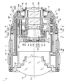
- FIG. 3 is a side sectional view showing a schematic configuration inside a lens barrel at a wide-angle end.
- FIG. 2 is a plan sectional view showing a schematic configuration inside a lens barrel at a wide-angle end.
- FIG. 8 is a diagram illustrating a moving state of each lens group when a zoom operation is performed.
- FIG. 3 is a diagram showing a schematic configuration inside a lens barrel at a telephoto end.
- FIG. 5 is a sectional view taken along line 5-5 of FIGS. 1 and 2.
- FIG. 6 is a sectional view taken along line 6-6 of FIGS. 1 and 2;
- FIG. 10 is a diagram illustrating a state in which the front holding frame of the third lens group is fixed by magnetic force.
- FIG. 4 is a side sectional view showing a schematic configuration inside a lens barrel in which a second lens group is a camera shake correction lens. It is a figure showing the modification of the state where the 3rd lens group front group holding frame is fixed by magnetic force.
- FIG. 3 is a block diagram illustrating an electrical configuration of the interchangeable lens. It is the perspective view which looked at the camera system from diagonally forward. It is a rear view of a camera main body.
- FIG. 1 is a side sectional view showing a schematic configuration inside the lens barrel at the wide angle end
- FIG. 2 is a plan sectional view showing a schematic configuration inside the lens barrel at the wide angle end.
- the interchangeable lens 1 is a so-called zoom lens, and mainly includes a lens barrel main body 10 to which a lens is assembled, and an exterior body 100 that covers the outer circumference of the lens barrel main body 10.
- the zoom ring 7 is connected to the cam barrel 14 by a connecting member (not shown), and by rotating the zoom ring 7, the cam barrel 14 rotates to change the focal length.
- the interchangeable lens 1 of the present embodiment has a manual focus adjustment function, and the focus can be manually adjusted by rotating a focus ring 8 provided on an outer peripheral portion thereof.
- the interchangeable lens 1 of the present embodiment has an aperture setting function manually, and the aperture can be manually set by rotating an aperture ring 9 provided on an outer peripheral portion thereof.
- the zoom ring 7, the focus ring 8, and the aperture ring 9 are examples of a plurality of operation rings.
- the lens barrel main body 10 has a fixed barrel 12 and a cam barrel 14.
- the cam cylinder 14 is fitted to the inner peripheral part of the fixed cylinder 12 and holds the inner peripheral part of the fixed cylinder 12 so as to be rotatable in the circumferential direction.
- the fixed cylinder 12 is an example of a fixed frame.
- the fixed cylinder 12 has a mount 16 at its base end (end on the image plane side).
- the mount 16 is constituted by a so-called bayonet mount.
- the mount 16 is attached to the base end of the fixed cylinder 12 by a plurality of mount fixing screws 18.
- the fixed cylinder 12 is configured such that the base end has the smallest outer diameter.
- the outer diameter of the mount 16 is equal to or less than the outer diameter of the base end of the fixed cylinder 12. More specifically, the outer diameter of the flange portion 16A having the largest outer diameter is equal to or less than the outer diameter of the base end of the fixed cylinder 12. In the present embodiment, the outer diameter of the flange portion 16 ⁇ / b> A is the same as the outer diameter of the base end of the fixed cylinder 12.
- a plurality of lenses are arranged inside the fixed barrel 12. Specifically, a first lens group G1, a second lens group G2, a third lens group G3, a fourth lens group G4, and a fifth lens group G5 are arranged in order from the object side along the optical axis Z. .
- Each lens group includes at least one lens.
- the first lens group G1, the second lens group G2, the third lens group G3, the fourth lens group G4, and the fifth lens group G5 are examples of an optical member, and the third lens group G3 is an example of a first optical member.
- the fourth lens group G4 is an example of a second optical member.
- ⁇ ⁇ Aperture St is arranged inside fixed cylinder 12.
- the stop St is disposed between the first lens group G1 and the second lens group G2.
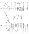
- FIG. 3 is a diagram showing a moving state of each lens group when a zoom operation is performed.
- FIG. 4 is a side sectional view showing a schematic configuration inside the lens barrel at the telephoto end.
- 3A shows the lens arrangement at the wide-angle end
- FIG. 3B shows the lens arrangement at the telephoto end.
- the first lens group G1 to the fourth lens group G4 are lens groups that move with respect to the image plane Sim by a zoom operation.
- the fifth lens group G5 is a lens group fixed to the image plane Sim by a zoom operation.
- the first lens group G1 moves along a movement path AL1 by a zoom operation
- the second lens group G2 moves along a movement path AL2 by a zoom operation.
- the third lens group G3 moves along the movement path AL3 by the zoom operation
- the fourth lens group G4 moves along the movement path AL4 by the zoom operation.
- the stop St moves integrally with the second lens group G2.
- the third lens group G3 includes a front group G3a of the third lens group and a rear group G3b of the third lens group.
- the front group G3a of the third lens group is a lens group for correcting field curvature.
- the front group G3a of the third lens group is a lens group that can move independently of the other lens groups. When correcting the field curvature, the front group G3a of the third lens group is moved along the optical axis Z.
- the fourth lens group G4 is a lens group for focusing.
- the fourth lens group G4 is a lens group that can move independently of the other lens groups. When adjusting the focus, the fourth lens group G4 is moved along the optical axis Z.
- the first lens group holding frame 20 is provided with three first lens group driving cam pins 32 on the outer peripheral portion thereof.
- the three first lens group driving cam pins 32 are arranged at equal intervals in the circumferential direction.
- Each of the first lens group driving cam pins 32 is fitted into the first lens group driving cam groove 14A provided in the cam barrel 14 and the first lens group driving straight groove provided in the fixed barrel 12, respectively.
- the first lens group G1 is held in the fixed barrel 12.
- the cam barrel 14 is rotated, the first lens group G1 moves within the fixed barrel 12 along the optical axis Z.
- the second lens group G ⁇ b> 2 is held in the second lens group holding frame 22 and arranged in the fixed cylinder 12.
- the second lens group holding frame 22 is provided with three second lens group driving cam pins 34 on the outer peripheral portion thereof.
- the three second lens group driving cam pins 34 are arranged at equal intervals in the circumferential direction.
- the second lens group driving cam pins 34 are fitted in the second lens group driving cam grooves 14B provided in the cam barrel 14 and the second lens group driving straight grooves provided in the fixed barrel 12, respectively.
- the second lens group G2 is held in the fixed barrel 12.
- the cam barrel 14 is rotated, the second lens group G2 moves along the optical axis Z in the fixed barrel 12.
- an aperture unit 30 constituting the aperture St is assembled to the second lens group holding frame 22.
- the stop St is disposed in the fixed barrel 12 and moves together with the second lens group G2.
- the third lens group G ⁇ b> 3 is held in the third lens group holding frame 24 and arranged in the fixed cylinder 12.
- the third lens group holding frame 24 includes a third lens group rear group holding frame 24A and a third lens group front group holding frame 24B held on the inner peripheral portion of the third lens group rear group holding frame 24A. Is done.
- the third lens group front group holding frame 24B is held movably along the optical axis Z on the inner peripheral portion of the third lens group rear group holding frame 24A.
- the third lens group front group G3a is held by the third lens group front group holding frame 24B.
- the third lens group rear group G3b is held by the third lens group rear group holding frame 24A.
- FIG. 5 is a sectional view taken along line 5-5 of FIGS. 1 and 2.
- the third lens group rear group holding frame 24A is provided with three third lens group driving cam pins 36 on its outer peripheral portion.
- the three third lens group driving cam pins 36 are arranged at equal intervals in the circumferential direction.
- the third lens group driving cam pins 36 are fitted into the third lens group driving cam grooves 14C provided in the cam barrel 14 and the third lens group driving straight grooves 12C provided in the fixed barrel 12, respectively. .
- a first main shaft 48 and a first sub shaft 50 are provided on the inner peripheral portion of the third lens group rear group holding frame 24A.
- the first main shaft 48 and the first sub shaft 50 are arranged at positions facing each other with the optical axis Z interposed therebetween (arranged at intervals of 180 ° in the circumferential direction), and are arranged along the optical axis Z, respectively.
- the third lens group front group holding frame 24B is provided with a first main axis 48 and a first sub axis provided on the third lens group rear group holding frame 24A via the first main guide section 52 and the first sub guide section 54. 50 slidably supported. Thereby, the third lens group front group holding frame 24B is movably supported along the optical axis Z on the inner peripheral portion of the third lens group rear group holding frame 24A.
- the third lens group rear group holding frame 24A is an example of a first frame
- the third lens group front group holding frame 24B is an example of a first movable frame.
- the third lens group front group holding frame 24B is driven by the first motor 56, and moves along the optical axis Z along the inner periphery of the third lens group rear group holding frame 24A.
- the first motor 56 is constituted by a moving magnet type voice coil motor.
- the third lens group front group holding frame 24B is provided with a plurality of first magnets 56A and a plurality of inner yokes 56B of the voice coil motor constituting the first motor 56.
- the third lens group rear group holding frame 24A is provided with a first coil 56C of a voice coil motor constituting the first motor 56 and a plurality of outer yokes 56D.
- the first motor 56 is an example of a first driving unit.
- the third lens group G3 is held in the fixed barrel 12.
- the third lens group G3 moves along the optical axis Z in the fixed barrel 12 (the third lens group front group G3a and the third lens group rear group G3b are integrally formed). And moves within the fixed cylinder 12 along the optical axis Z.)
- the third lens group front group G3a moves alone along the optical axis Z (the third lens group front group G3a moves independently along the optical axis Z). .).
- the field curvature is corrected.
- the fourth lens group holding frame 26 includes a fourth lens group base holding frame 26A, and a fourth lens group movable holding frame 26B held on the inner periphery of the fourth lens group base holding frame 26A. .
- the fourth lens group movable holding frame 26B is supported movably along the optical axis Z on the inner peripheral portion of the fourth lens group base holding frame 26A.
- the fourth lens group G4 is held on the inner periphery of the fourth lens group movable holding frame 26B.
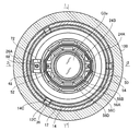
- FIG. 6 is a sectional view taken along line 6-6 in FIGS. 1 and 2.
- the fourth lens group base holding frame 26A is provided with three fourth lens group driving cam pins 38 on its outer peripheral portion.
- the three fourth lens group driving cam pins 38 are arranged at equal intervals in the circumferential direction.
- the fourth lens group driving cam pins 38 are fitted into the fourth lens group driving cam grooves 14D provided in the cam barrel 14 and the fourth lens group driving straight grooves 12D provided in the fixed barrel 12, respectively. .
- the fourth lens group base holding frame 26A is provided with a second main shaft 68 and a second sub shaft 70.
- the second main shaft 68 and the second sub shaft 70 are arranged at positions opposing each other across the optical axis Z (arranged at 180 ° intervals in the circumferential direction), and are arranged along the optical axis Z, respectively.
- the fourth lens group movable holding frame 26B is connected to the second main shaft 68 and the second sub shaft 70 provided on the fourth lens group base holding frame 26A via the second main guide portion 72 and the second sub guide portion 74. It is slidably supported. Thus, the fourth lens group movable holding frame 26B is movably supported along the optical axis Z on the inner peripheral portion of the fourth lens group base holding frame 26A.
- the fourth lens group base holding frame 26A is an example of a second frame
- the fourth lens group movable holding frame 26B is an example of a second movable frame.
- the fourth lens group movable holding frame 26B is driven by the second motor 58 as a focus motor, and moves along the optical axis Z along the inner periphery of the fourth lens group base holding frame 26A.
- the second motor 58 is constituted by a moving coil type voice coil motor.
- the fourth lens group movable holding frame 26B is provided with a plurality of second coils 58A of a voice coil motor constituting the second motor 58.
- the fourth lens group base holding frame 26A is provided with a plurality of second magnets 58B, a plurality of inner yokes 58C, and a plurality of outer yokes 58D of the voice coil motor constituting the second motor 58.
- the second motor 58 is an example of a second driving unit.
- the fourth lens group G4 is held in the fixed barrel 12.
- the fourth lens group G4 moves along the optical axis Z in the fixed barrel 12.
- the fourth lens group G4 moves independently along the optical axis Z.
- the focus adjustment is performed by independently moving the fourth lens group G4.
- the fourth lens group movable holding frame 26B has a balance weight 76 at a position opposite to the fourth lens group G4 in the direction of the optical axis Z. With the balance weight 76, the position of the center of gravity of the fourth lens group movable holding frame 26B and the fourth lens group G4 can be moved to the front end side (object side).
- the balance weight 76 can be provided by fitting the ring-shaped balance weight 76 to the object side of the cylindrical fourth lens group movable holding frame 26B.
- the fourth lens group movable holding frame 26B can be supported by the second main guide portion 72 and the second sub guide portion 74. The four-lens group movable holding frame 26B can be moved smoothly.
- the fifth lens group G ⁇ b> 5 is held in the fifth lens group holding frame 28 and arranged in the fixed cylinder 12.
- the fifth lens group holding frame 28 is attached to the fixed barrel 12 by a plurality of fifth lens group fixing screws.
- the lens barrel main body 10 is configured as described above.
- the first lens group G1, the second lens group G2, the third lens group G3, and the fourth lens group G4 move along the optical axis Z. Thereby, zooming is performed.
- the front group G3a of the third lens group moves independently along the optical axis Z.
- the interchangeable lens 1 corrects the curvature of field by independently moving the front group G3a of the third lens group.
- the fourth lens group movable holding frame 26B is a cylindrical body that holds the fourth lens group G4 on one end side (image side) and has a cavity on the other end side (object side).
- a part of the third lens group rear group holding frame 24A and a part of the third lens group front group holding frame 24B that hold the third lens group G3 are configured to be able to enter this cavity at the wide angle end.
- the lens barrel body 10 moves the third lens group G3 in a plane orthogonal to the optical axis. Thereby, the adjustment of the optical axis Z is performed.
- the third lens group G3 and the fourth lens group G4 in the interchangeable lens 1 are such that the third lens group G3 and the fourth lens group G4 are close at the wide angle end, and are close at the telephoto end. It will be the farthest away.
- the third lens group front group holding frame 24B is driven by a voice coil motor constituting the first motor 56. Therefore, when the power supply to the first coil 56C is stopped, the front lens group holding frame 24B of the third lens group can freely move within the range of the first main shaft 48 and the first sub shaft 50.
- the second motor 58 for driving the fourth lens group G4 is provided to fix the third lens group front group holding frame 24B in a state where the power supply to the first coil 56C is stopped.
- the front lens holding frame 24B of the third lens group is fixed using the magnetic material thus obtained.
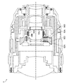
- FIG. 7 is a diagram illustrating a state in which the third lens group front group holding frame is fixed at the wide angle end.
- the fixing of the third lens group front group holding frame 24B is performed by the magnetic force between the first magnet 56A of the first motor 56 and the inner yoke 58C and the outer yoke 58D, which are magnetic materials provided in the second motor 58. It is fixed by attracting.
- the first magnet 56A is provided on the third lens group front group holding frame 24B.
- the inner yoke 58C and the outer yoke 58D are provided on the fourth lens group base holding frame 26A, and the fourth lens group base holding frame 26A is held by the cam barrel 14.
- the third lens group front group holding frame 24B is fixed to the fourth lens group base holding frame 26A and the cam barrel 14.
- the third lens group G3 and the fourth lens group G4 come close to each other. That is, as shown in FIG. 6, the first magnet 56A provided in the third lens group front group holding frame 24B and the inner yoke 58C and the outer yoke 58D of the second motor 58 are arranged close to each other.
- the front frame holding frame 24B of the third lens group is disposed at the moving end that does not move to the image plane side. Therefore, before the energization of the first coil 56C is stopped, the arrangement of the lens groups is moved so that the arrangement of the lens groups is at the wide-angle end as shown in FIG.
- the third lens group front group holding frame 24B cannot move to the image plane side of the interchangeable lens 1.
- the third lens group front group holding frame 24B is positioned on the object side of the interchangeable lens 1. Also does not move. Therefore, the third lens group front group holding frame 24B can be fixed in the interchangeable lens 1.
- the plurality of first magnets 56A are preferably arranged symmetrically with respect to the center of the third lens group front group holding frame 24B. Since the third lens group front group holding frame 24B is formed of a cylindrical body, any one of the first magnets 56A, the inner yoke 58C, and the outer yoke 58D can be formed by symmetrically arranging the plurality of first magnets 56A. It can be securely approached and can be fixed by magnetic force.
- the balance weight 76 of the fourth lens group movable holding frame 26B and the first magnet 56A of the third lens group front group holding frame 24B can be attracted by magnetic force. It can. Thereby, the fourth lens group movable holding frame 26B can be fixed to the third lens group front group holding frame 24B fixed to the inner yoke 58C and the outer yoke 58D, and the fourth lens group movable holding frame 26B moves. Can be prevented.
- a magnetic material used for the balance weight 76 iron, cobalt, nickel, or an alloy thereof can be used.
- FIG. 8 is a side cross-sectional view showing a schematic configuration inside a lens barrel of an embodiment in which the second lens group G2 of the above embodiment is a lens for camera shake correction.
- the second lens group (lens for correcting camera shake) G2 is held by the lens holding frame 82 for correcting camera shake and arranged in the fixed barrel 12.
- the camera shake correction lens holding frame 82 includes a camera shake correction lens base holding frame 82A, and a camera shake correction lens movable holding frame 82B held on the inner periphery of the camera shake correction lens base holding frame 82A.
- the second lens group (camera shake correction lens) G2 is held on the inner peripheral portion of the camera shake correction lens movable holding frame 82B.
- the camera shake correction lens base holding frame 82A is an example of a second frame
- the camera shake correction lens movable holding frame 82B is an example of a second movable frame.
- the second lens group (lens for camera shake correction) G2 is an example of a second optical member.
- the camera shake correction lens base holding frame 82A is provided with three camera shake correction lens driving cam pins 84 on the outer peripheral portion thereof.
- the three camera shake correcting lens driving cam pins 84 are arranged at equal intervals in the circumferential direction.
- Each of the camera shake correction lens driving cam pins 84 is provided. Each of them is fitted into a camera shake correction lens driving cam groove 14E provided in the cam barrel 14 and a camera shake correction lens driving straight groove provided in the fixed barrel 12.
- the diaphragm unit 30 that forms the diaphragm St is attached to the camera shake correction lens holding frame 82.
- the camera-shake correction lens base holding frame 82A and the camera-shake correction lens movable holding frame 82B are three steel balls 86 arranged at equal intervals in the circumferential direction on the inner periphery of the camera-shake correction lens base holding frame 82A. And are supported by four springs 88. Further, the camera shake correction lens movable holding frame 82B is driven by an unillustrated X-axis motor and Y-axis motor 90, and is movable in a direction orthogonal to the optical axis Z.
- the spring 88 is an urging member for urging the camera shake correction lens movable holding frame 82B with respect to the camera shake correction lens base holding frame 82A with the steel ball 86 interposed therebetween.
- the Y-axis motor 90 is constituted by a moving coil type voice coil motor.
- the camera shake correction lens movable holding frame 82B is provided with a coil 90C of a voice coil motor constituting the Y-axis motor 90.
- the camera shake correction lens base holding frame 82A is provided with a magnet 90A of a voice coil motor constituting the Y-axis motor 90 and yokes 90B and 90D.
- An X-axis motor (not shown) is similarly configured.
- the X-axis motor and the Y-axis motor 90 are an example of a second driving unit.
- the second lens group (camera shake correction lens) G2 is held in the fixed barrel 12.
- the second lens group (lens for correcting camera shake) G2 moves in the direction perpendicular to the optical axis Z.
- FIG. 9 is a diagram illustrating a state in which the front holding frame of the third lens group is fixed to the lens base holding frame for camera shake correction.
- the second lens group G2 includes an X-axis motor and a Y-axis motor 90 for moving the camera shake correction lens by using a camera shake correction lens as described above.
- the third lens group front group holding frame 24B is fixed to the third lens group front group holding frame 24B using a magnetic body provided on the X-axis motor and the Y-axis motor 90.
- the fixing of the third lens group front group holding frame 24 ⁇ / b> B is performed between the first magnet 56 ⁇ / b> A of the first motor 56 and the yoke 90 ⁇ / b> B which is a magnetic material provided in the Y-axis motor 90. It is fixed by attracting by the magnetic force of.
- the yoke 90B is provided on a camera shake correction lens base holding frame 82A, and the camera shake correction lens base holding frame 82A is held by the cam barrel 14.
- the third lens group front group holding frame 24B is fixed to the camera shake correction lens base holding frame 82A and the cam barrel 14.
- the power supply to the first motor 56 to the first coil 56C is stopped before the third lens group is stopped.
- the power supply to the first coil 56C is stopped in a state where the group holding frame 24B is arranged at the distal end side in the interchangeable lens 1, that is, at the moving end where the third lens group front group holding frame 24B does not move toward the distal end side. .
- the magnetic force between the first magnet 56A of the first motor 56 and the yoke 90B of the camera-shake correction lens base holding frame 82A can attract each other.
- the movement of the group holding frame 24B can be prevented and the group holding frame 24B can be fixed in the interchangeable lens 1.
- FIG. 10 is a block diagram showing an electrical configuration of the interchangeable lens.
- the interchangeable lens 1 includes a third lens group front group drive section 210 that drives the third lens group front group G3a, a third lens group front group position detection section 212 that detects the position of the third lens group front group G3a, and a fourth The fourth lens group driving unit 214 for driving the lens group G4, the fourth lens group position detecting unit 216 for detecting the position of the fourth lens group G4, the diaphragm driving unit 218 for driving the diaphragm St, and the temperature in the interchangeable lens 1
- a temperature control unit 220 for detecting a focus operation, a focus operation detection unit 222 for detecting a focus operation, a zoom setting detection unit 224 for detecting a zoom operation, an aperture setting detection unit 226 for detecting an aperture operation, and overall control of the entire operation of the interchangeable lens 1.
- a lens control unit 228 that performs the operation.
- the third lens group front group drive section 210 includes the first motor 56 and its drive circuit.
- the third lens group front group drive section 210 drives the first motor 56 in response to a command from the lens control section 228 to move the third lens group front group G3a along the optical axis Z.
- the third lens group front group position detection unit 212 includes a position detection sensor (not shown).
- the position detection sensor is configured by a magnetic sensor such as a Hall element or a magneto-resistive element (Magneto-Resistive-Sensor).
- the third lens group front group position detection unit 212 detects the position of the third lens group front group G3a with a position detection sensor, and outputs the detection result to the lens control unit 228.
- the position of the third lens group front group G3a is a position with respect to the third lens group rear group G3b, and is a position in the third lens group rear group holding frame 24A.
- the fourth lens group driving unit 214 includes the second motor 58 and a driving circuit thereof.
- the fourth lens group drive unit 214 drives the second motor 58 in response to a command from the lens control unit 228 to move the fourth lens group G4 along the optical axis Z.
- the fourth lens group position detecting section 216 includes a position detecting sensor (not shown).
- the position detection sensor is composed of, for example, a magnetic sensor such as a Hall element or a magnetoresistive element.
- the fourth lens group position detector 216 detects the position of the fourth lens group G4 with a position sensor, and outputs the detection result to the lens controller 228.
- the position of the fourth lens group G4 is a position in the fourth lens group holding frame 26.
- the aperture drive unit 218 includes an aperture motor and a drive circuit therefor.
- An aperture motor (not shown) is provided in the aperture unit 30.
- the aperture driving unit 218 drives an aperture motor in response to a command from the lens control unit 228 to open and close the aperture St.
- the temperature detection unit 220 includes a temperature sensor (not shown).
- the temperature sensor is provided in the aperture unit 30, for example.
- Temperature detecting section 220 detects the temperature in interchangeable lens 1 with a temperature sensor, and outputs the detection result to lens control section 228.
- the focus operation detection unit 222 detects the amount of rotation operation of the focus ring 8 and outputs the detection result to the lens control unit 228.
- the lens control unit 228 detects a focus operation amount based on an output from the focus operation detection unit 222.
- the zoom setting detection unit 224 detects the setting position of the zoom ring 7 and outputs the detection result to the lens control unit 228.
- the lens control unit 228 detects a zoom set value (focal length) based on the output from the zoom setting detection unit 224.
- the aperture setting detector 226 detects the set position of the aperture ring 9 and outputs the detection result to the lens controller 228.
- the lens control unit 228 detects a set value of the aperture (aperture value) based on an output from the aperture setting detection unit 226.
- the lens control unit 228 controls the operation of each unit based on the operation of the focus ring 8, the zoom ring 7, and the aperture ring 9. Specifically, when the manual focus is set, the fourth lens group drive unit 214 is driven based on the rotation amount of the focus ring 8 to move the fourth lens group G4. Further, based on the setting of the zoom ring 7, the third lens group front group driving unit 210 and the fourth lens group driving unit 214 are driven to move the third lens group front group G3a and the fourth lens group G4 to predetermined positions. Let it. Further, the aperture driving unit 218 is driven based on the setting of the aperture ring 9, and the aperture St is set to a predetermined aperture (aperture value).
- the lens control unit 228 controls the operation of each unit according to a command from the camera on which the interchangeable lens 1 is mounted.
- the fourth lens group driving unit 214 is driven based on autofocus information from the camera to move the fourth lens group G4 to a predetermined position.
- the aperture driving unit 218 is driven based on the aperture setting information from the camera, and the aperture St is set to a predetermined opening amount.
- the lens control unit 228 communicates with the camera control unit 230 of the camera, and receives a drive command for each unit from the camera control unit 230.
- the camera control unit 230 transmits zoom setting information, aperture setting information, focus position information, and the like. Communication between the lens control unit 228 and the camera control unit 230 is performed via a terminal 16 ⁇ / b> B provided on the mount 16.
- the lens control section 228 drives the third lens group front group drive section 210 based on the temperature detected by the temperature detection section 220 to move the third lens group front group G3a to a predetermined position.
- the lens control unit 228 is configured by, for example, a computer having a CPU (Central Processing Unit), a ROM (Read Only Memory), and a RAM (Random Access Memory), and by executing a predetermined program. And implement various control functions.
- a computer having a CPU (Central Processing Unit), a ROM (Read Only Memory), and a RAM (Random Access Memory), and by executing a predetermined program. And implement various control functions.
- a CPU Central Processing Unit
- ROM Read Only Memory
- RAM Random Access Memory
- FIG. 11 and FIG. 12 are external views showing an example of the configuration of a camera system using the lens barrel of the present embodiment as an example of an imaging apparatus.
- FIG. 11 is a perspective view of the camera system as viewed obliquely from the front
- FIG. 12 is a rear view of the camera body.
- the camera system 110 is a mirrorless digital single-lens camera or a digital single-lens reflex camera comprising the interchangeable lens 1 and a camera body 150 to which the interchangeable lens 1 is detachable.
- the imaging device is not limited to the camera system shown in FIGS. 11 and 12, and it goes without saying that a mirrorless digital single-lens camera or a digital single-lens reflex camera in which a lens and a camera body are integrally formed may be used. .
- a body mount 160 on which the interchangeable lens 1 is mounted, a finder window 120 of an optical finder, and the like are provided.
- a shutter release button 122, a shutter speed dial 123, An exposure compensation dial 124, a power lever 125, and a built-in flash 130 are provided.
- a monitor 116, an eyepiece 126 of an optical finder, a MENU and OK key 127, a cross key 128, a play button 129, and the like are mainly provided on the rear surface of the camera body 150.
- the monitor 116 displays a live view image in the imaging mode, reproduces and displays an image captured in the reproduction mode, and functions as a display unit for displaying various menu screens.
- An MENU and OK key 127 is an operation key having both a function as a menu button for issuing a command to display a menu on the screen of the monitor 116 and a function as an OK button for instructing selection and execution of the selected contents. It is.
- the cross key 128 is an operation unit for inputting four directions of up, down, left, and right, and functions as a button for selecting an item from a menu screen or instructing selection of various setting items from each menu.
- the up key and the down key of the cross key 128 function as a zoom switch at the time of image capturing or a reproduction zoom switch at the time of the reproduction mode.
- Function as The playback button 129 is a button for switching to a playback mode in which a captured still image or a moving image is displayed on the monitor 116.
- the third lens group front group holding frame is used when the lens barrel and the imaging device are transported in a state where the power is turned off. Since movement of 24B can be prevented, breakage of the optical member can be prevented.
Landscapes
- Physics & Mathematics (AREA)
- General Physics & Mathematics (AREA)
- Engineering & Computer Science (AREA)
- Optics & Photonics (AREA)
- Chemical & Material Sciences (AREA)
- Combustion & Propulsion (AREA)
- Electromagnetism (AREA)
- Power Engineering (AREA)
- Signal Processing (AREA)
- Multimedia (AREA)
- General Engineering & Computer Science (AREA)
- Lens Barrels (AREA)
- Adjustment Of Camera Lenses (AREA)
- Studio Devices (AREA)
Abstract
L'invention concerne un barillet d'objectif et un dispositif de capture d'image qui sont conçus de telle sorte qu'un cadre mobile peut être fixé à un cadre fixe sans qu'un élément servant à fixer l'élément mobile doive être fourni. Ce barillet d'objectif est pourvu : d'un premier aimant (56A) disposé sur un troisième cadre de maintien de groupe avant pour groupe de lentilles (24B) ; d'un premier moteur (56) servant à entraîner le troisième cadre de maintien de groupe avant pour groupe de lentilles (24B) au moyen d'une première bobine (56C) ; d'une seconde bobine (58A) disposée sur un quatrième cadre de maintien mobile pour groupe de lentilles (26B) ; et un second moteur (58) servant à entraîner le quatrième cadre de maintien mobile pour groupe de lentilles (26B) au moyen d'un second aimant (58B) disposé sur un quatrième cadre de maintien de base pour groupe de lentilles (26A) fixé à un cylindre fixe (12) et à un cylindre de came (14). Lorsque l'alimentation en électricité de la première bobine (56C) est coupée, le troisième cadre de maintien de groupe avant pour groupe de lentilles (24B) est fixé par une force magnétique agissant entre le premier aimant (56A) et des culasses interne (58C) et externe (58D), les culasses interne et externe (58C, 58D) étant disposées sur le quatrième cadre de maintien de base pour groupe de lentilles (26A).
Priority Applications (3)
| Application Number | Priority Date | Filing Date | Title |
|---|---|---|---|
| CN201980035009.7A CN112166373B (zh) | 2018-06-29 | 2019-06-05 | 镜头镜筒及摄像装置 |
| JP2020527337A JP6841979B2 (ja) | 2018-06-29 | 2019-06-05 | レンズ鏡筒及び撮像装置 |
| US17/117,640 US11971602B2 (en) | 2018-06-29 | 2020-12-10 | Lens barrel and imaging device |
Applications Claiming Priority (2)
| Application Number | Priority Date | Filing Date | Title |
|---|---|---|---|
| JP2018124906 | 2018-06-29 | ||
| JP2018-124906 | 2018-06-29 |
Related Child Applications (1)
| Application Number | Title | Priority Date | Filing Date |
|---|---|---|---|
| US17/117,640 Continuation US11971602B2 (en) | 2018-06-29 | 2020-12-10 | Lens barrel and imaging device |
Publications (1)
| Publication Number | Publication Date |
|---|---|
| WO2020003942A1 true WO2020003942A1 (fr) | 2020-01-02 |
Family
ID=68985608
Family Applications (1)
| Application Number | Title | Priority Date | Filing Date |
|---|---|---|---|
| PCT/JP2019/022369 WO2020003942A1 (fr) | 2018-06-29 | 2019-06-05 | Barillet d'objectif et dispositif de capture d'image |
Country Status (4)
| Country | Link |
|---|---|
| US (1) | US11971602B2 (fr) |
| JP (1) | JP6841979B2 (fr) |
| CN (1) | CN112166373B (fr) |
| WO (1) | WO2020003942A1 (fr) |
Cited By (2)
| Publication number | Priority date | Publication date | Assignee | Title |
|---|---|---|---|---|
| WO2022097506A1 (fr) * | 2020-11-05 | 2022-05-12 | ソニーグループ株式会社 | Barillet de lentille, procédé de commande et dispositif d'imagerie |
| WO2022097505A1 (fr) * | 2020-11-05 | 2022-05-12 | ソニーグループ株式会社 | Barillet de lentille, procédé de commande et dispositif d'imagerie |
Families Citing this family (4)
| Publication number | Priority date | Publication date | Assignee | Title |
|---|---|---|---|---|
| JP2021156906A (ja) * | 2018-05-01 | 2021-10-07 | オリンパス株式会社 | 光学ユニット |
| WO2020003940A1 (fr) * | 2018-06-29 | 2020-01-02 | 富士フイルム株式会社 | Barrillet d'objectif |
| CN210327730U (zh) * | 2019-07-29 | 2020-04-14 | 广景视睿科技(深圳)有限公司 | 一种调焦装置 |
| JP2021179504A (ja) * | 2020-05-12 | 2021-11-18 | キヤノン株式会社 | レンズ鏡筒、撮像装置 |
Citations (4)
| Publication number | Priority date | Publication date | Assignee | Title |
|---|---|---|---|---|
| JP2005141188A (ja) * | 2003-11-04 | 2005-06-02 | Hii Choi Douu | 携帯電話用デジタルカメラの焦点変換装置 |
| JP2013025081A (ja) * | 2011-07-21 | 2013-02-04 | Nikon Corp | レンズ鏡筒及びカメラ |
| JP2013182165A (ja) * | 2012-03-02 | 2013-09-12 | Nikon Corp | レンズ鏡筒および光学装置 |
| JP2018066915A (ja) * | 2016-10-20 | 2018-04-26 | パナソニックIpマネジメント株式会社 | レンズ鏡筒 |
Family Cites Families (16)
| Publication number | Priority date | Publication date | Assignee | Title |
|---|---|---|---|---|
| JP2002023037A (ja) * | 2000-07-07 | 2002-01-23 | Sony Corp | レンズ鏡筒 |
| CN100520471C (zh) * | 2006-08-01 | 2009-07-29 | 扬明光学股份有限公司 | 镜头模块 |
| CN101131526B (zh) * | 2006-08-25 | 2010-05-26 | 富准精密工业(深圳)有限公司 | 相机马达结构 |
| JP2008310169A (ja) * | 2007-06-15 | 2008-12-25 | Fujinon Corp | 撮影装置、携帯機器 |
| US20180325547A1 (en) * | 2007-06-29 | 2018-11-15 | Actuated Medical, Inc. | Medical Tool for Reduced Force Penetration for Vascular Access |
| US7990463B2 (en) * | 2008-02-05 | 2011-08-02 | Power Gate Optical Inc | Multi-stage lens driving device |
| CN101750709B (zh) * | 2008-12-15 | 2012-11-14 | 百隆光电股份有限公司 | 可使镜头模组遂行自动微拍功能的驱动控制方法及装置 |
| JP2010217321A (ja) * | 2009-03-13 | 2010-09-30 | Fujifilm Corp | レンズ装置 |
| WO2012107965A1 (fr) * | 2011-02-09 | 2012-08-16 | パナソニック株式会社 | Barillet de lentille, et dispositif de prise de vue |
| JP2013045078A (ja) | 2011-08-26 | 2013-03-04 | Nikon Corp | レンズ鏡筒および撮影装置 |
| CN102590979B (zh) | 2012-01-17 | 2013-10-23 | 博立码杰通讯(深圳)有限公司 | 焦距调节装置和光学成像装置 |
| US9179067B2 (en) * | 2012-05-10 | 2015-11-03 | Panasonic Intellectual Property Corporation Of America | Camera drive device with a moveable unit that is freely rotatable relative to a fixed unit |
| JP2017003742A (ja) * | 2015-06-09 | 2017-01-05 | オリンパス株式会社 | レンズ駆動装置 |
| WO2016199284A1 (fr) * | 2015-06-11 | 2016-12-15 | オリンパス株式会社 | Mécanisme d'entraînement d'élément optique, endoscope, et dispositif d'imagerie |
| JP6614852B2 (ja) * | 2015-08-07 | 2019-12-04 | オリンパス株式会社 | 撮像装置 |
| JP2017173756A (ja) * | 2016-03-25 | 2017-09-28 | Hoya株式会社 | 撮像装置 |
-
2019
- 2019-06-05 WO PCT/JP2019/022369 patent/WO2020003942A1/fr active Application Filing
- 2019-06-05 JP JP2020527337A patent/JP6841979B2/ja active Active
- 2019-06-05 CN CN201980035009.7A patent/CN112166373B/zh active Active
-
2020
- 2020-12-10 US US17/117,640 patent/US11971602B2/en active Active
Patent Citations (4)
| Publication number | Priority date | Publication date | Assignee | Title |
|---|---|---|---|---|
| JP2005141188A (ja) * | 2003-11-04 | 2005-06-02 | Hii Choi Douu | 携帯電話用デジタルカメラの焦点変換装置 |
| JP2013025081A (ja) * | 2011-07-21 | 2013-02-04 | Nikon Corp | レンズ鏡筒及びカメラ |
| JP2013182165A (ja) * | 2012-03-02 | 2013-09-12 | Nikon Corp | レンズ鏡筒および光学装置 |
| JP2018066915A (ja) * | 2016-10-20 | 2018-04-26 | パナソニックIpマネジメント株式会社 | レンズ鏡筒 |
Cited By (2)
| Publication number | Priority date | Publication date | Assignee | Title |
|---|---|---|---|---|
| WO2022097506A1 (fr) * | 2020-11-05 | 2022-05-12 | ソニーグループ株式会社 | Barillet de lentille, procédé de commande et dispositif d'imagerie |
| WO2022097505A1 (fr) * | 2020-11-05 | 2022-05-12 | ソニーグループ株式会社 | Barillet de lentille, procédé de commande et dispositif d'imagerie |
Also Published As
| Publication number | Publication date |
|---|---|
| JP6841979B2 (ja) | 2021-03-10 |
| CN112166373A (zh) | 2021-01-01 |
| US11971602B2 (en) | 2024-04-30 |
| US20210096320A1 (en) | 2021-04-01 |
| CN112166373B (zh) | 2022-05-10 |
| JPWO2020003942A1 (ja) | 2021-04-01 |
Similar Documents
| Publication | Publication Date | Title |
|---|---|---|
| WO2020003942A1 (fr) | Barillet d'objectif et dispositif de capture d'image | |
| JP4764075B2 (ja) | 像ぶれ補正装置、該像ぶれ補正装置を備えたレンズ鏡筒 | |
| EP2141539B1 (fr) | Dispositif de correction de flou et appareil optique | |
| US7460775B2 (en) | Optical apparatus including efficiently arranged shake correction means | |
| JP4513879B2 (ja) | 像ぶれ補正装置、レンズ鏡筒装置及びカメラ装置 | |
| JP4661915B2 (ja) | 像ぶれ補正装置、レンズ鏡筒装置及びカメラ装置 | |
| JP2007156351A (ja) | 像ぶれ補正装置、レンズ装置及び撮像装置 | |
| JP2015129855A (ja) | 像振れ補正装置、レンズ装置、および、撮像装置 | |
| JP2008180774A (ja) | レンズ鏡筒およびデジタルカメラ | |
| JP5504801B2 (ja) | ブレ補正装置及び光学機器 | |
| US20090245779A1 (en) | Mirror moving device and imaging apparatus | |
| US20150181125A1 (en) | Shake correction apparatus and image pickup apparatus thereof, and optical device mountable on image pickup apparatus | |
| JP6199502B2 (ja) | ズームレンズ鏡胴および交換レンズ並びにテレビカメラ装置 | |
| US20180067336A1 (en) | Image stabilization apparatus, lens apparatus, and imaging apparatus | |
| JP2010249934A (ja) | 像振れ補正装置 | |
| JP2018040861A (ja) | 像ブレ補正装置、レンズ鏡筒、および、撮像装置 | |
| US9223146B2 (en) | Optical apparatus and image-pickup apparatus including the same | |
| JP2019020536A (ja) | 撮像装置 | |
| WO2020003941A1 (fr) | Barillet d'objectif et dispositif de capture d'image | |
| JP2021021844A (ja) | レンズ装置および撮像装置 | |
| JP4941569B2 (ja) | 像ぶれ補正装置、レンズ鏡筒装置及びカメラ装置 | |
| JP2015203751A (ja) | レンズ鏡筒および撮像装置 | |
| JP2016057386A (ja) | 像ぶれ補正装置およびこれを有する光学機器 | |
| JP4574633B2 (ja) | 撮像装置 | |
| KR102608928B1 (ko) | 회전형 프리즘을 구비한 폴디드 카메라 모듈 |
Legal Events
| Date | Code | Title | Description |
|---|---|---|---|
| 121 | Ep: the epo has been informed by wipo that ep was designated in this application |
Ref document number: 19824590 Country of ref document: EP Kind code of ref document: A1 |
|
| ENP | Entry into the national phase |
Ref document number: 2020527337 Country of ref document: JP Kind code of ref document: A |
|
| NENP | Non-entry into the national phase |
Ref country code: DE |
|
| 122 | Ep: pct application non-entry in european phase |
Ref document number: 19824590 Country of ref document: EP Kind code of ref document: A1 |