WO2020003942A1 - Lens barrel and image capturing device - Google Patents
Lens barrel and image capturing device Download PDFInfo
- Publication number
- WO2020003942A1 WO2020003942A1 PCT/JP2019/022369 JP2019022369W WO2020003942A1 WO 2020003942 A1 WO2020003942 A1 WO 2020003942A1 JP 2019022369 W JP2019022369 W JP 2019022369W WO 2020003942 A1 WO2020003942 A1 WO 2020003942A1
- Authority
- WO
- WIPO (PCT)
- Prior art keywords
- lens group
- lens
- holding frame
- frame
- movable frame
- Prior art date
Links
Images


Classifications
-
- G—PHYSICS
- G02—OPTICS
- G02B—OPTICAL ELEMENTS, SYSTEMS OR APPARATUS
- G02B7/00—Mountings, adjusting means, or light-tight connections, for optical elements
- G02B7/02—Mountings, adjusting means, or light-tight connections, for optical elements for lenses
- G02B7/04—Mountings, adjusting means, or light-tight connections, for optical elements for lenses with mechanism for focusing or varying magnification
- G02B7/08—Mountings, adjusting means, or light-tight connections, for optical elements for lenses with mechanism for focusing or varying magnification adapted to co-operate with a remote control mechanism
-
- H—ELECTRICITY
- H02—GENERATION; CONVERSION OR DISTRIBUTION OF ELECTRIC POWER
- H02K—DYNAMO-ELECTRIC MACHINES
- H02K41/00—Propulsion systems in which a rigid body is moved along a path due to dynamo-electric interaction between the body and a magnetic field travelling along the path
- H02K41/02—Linear motors; Sectional motors
- H02K41/035—DC motors; Unipolar motors
- H02K41/0352—Unipolar motors
- H02K41/0354—Lorentz force motors, e.g. voice coil motors
- H02K41/0356—Lorentz force motors, e.g. voice coil motors moving along a straight path
-
- G—PHYSICS
- G02—OPTICS
- G02B—OPTICAL ELEMENTS, SYSTEMS OR APPARATUS
- G02B27/00—Optical systems or apparatus not provided for by any of the groups G02B1/00 - G02B26/00, G02B30/00
- G02B27/64—Imaging systems using optical elements for stabilisation of the lateral and angular position of the image
- G02B27/646—Imaging systems using optical elements for stabilisation of the lateral and angular position of the image compensating for small deviations, e.g. due to vibration or shake
-
- G—PHYSICS
- G02—OPTICS
- G02B—OPTICAL ELEMENTS, SYSTEMS OR APPARATUS
- G02B7/00—Mountings, adjusting means, or light-tight connections, for optical elements
- G02B7/02—Mountings, adjusting means, or light-tight connections, for optical elements for lenses
- G02B7/04—Mountings, adjusting means, or light-tight connections, for optical elements for lenses with mechanism for focusing or varying magnification
- G02B7/09—Mountings, adjusting means, or light-tight connections, for optical elements for lenses with mechanism for focusing or varying magnification adapted for automatic focusing or varying magnification
-
- G—PHYSICS
- G02—OPTICS
- G02B—OPTICAL ELEMENTS, SYSTEMS OR APPARATUS
- G02B7/00—Mountings, adjusting means, or light-tight connections, for optical elements
- G02B7/02—Mountings, adjusting means, or light-tight connections, for optical elements for lenses
- G02B7/04—Mountings, adjusting means, or light-tight connections, for optical elements for lenses with mechanism for focusing or varying magnification
- G02B7/10—Mountings, adjusting means, or light-tight connections, for optical elements for lenses with mechanism for focusing or varying magnification by relative axial movement of several lenses, e.g. of varifocal objective lens
- G02B7/102—Mountings, adjusting means, or light-tight connections, for optical elements for lenses with mechanism for focusing or varying magnification by relative axial movement of several lenses, e.g. of varifocal objective lens controlled by a microcomputer
-
- G—PHYSICS
- G03—PHOTOGRAPHY; CINEMATOGRAPHY; ANALOGOUS TECHNIQUES USING WAVES OTHER THAN OPTICAL WAVES; ELECTROGRAPHY; HOLOGRAPHY
- G03B—APPARATUS OR ARRANGEMENTS FOR TAKING PHOTOGRAPHS OR FOR PROJECTING OR VIEWING THEM; APPARATUS OR ARRANGEMENTS EMPLOYING ANALOGOUS TECHNIQUES USING WAVES OTHER THAN OPTICAL WAVES; ACCESSORIES THEREFOR
- G03B3/00—Focusing arrangements of general interest for cameras, projectors or printers
- G03B3/10—Power-operated focusing
-
- G—PHYSICS
- G03—PHOTOGRAPHY; CINEMATOGRAPHY; ANALOGOUS TECHNIQUES USING WAVES OTHER THAN OPTICAL WAVES; ELECTROGRAPHY; HOLOGRAPHY
- G03B—APPARATUS OR ARRANGEMENTS FOR TAKING PHOTOGRAPHS OR FOR PROJECTING OR VIEWING THEM; APPARATUS OR ARRANGEMENTS EMPLOYING ANALOGOUS TECHNIQUES USING WAVES OTHER THAN OPTICAL WAVES; ACCESSORIES THEREFOR
- G03B30/00—Camera modules comprising integrated lens units and imaging units, specially adapted for being embedded in other devices, e.g. mobile phones or vehicles
-
- G—PHYSICS
- G03—PHOTOGRAPHY; CINEMATOGRAPHY; ANALOGOUS TECHNIQUES USING WAVES OTHER THAN OPTICAL WAVES; ELECTROGRAPHY; HOLOGRAPHY
- G03B—APPARATUS OR ARRANGEMENTS FOR TAKING PHOTOGRAPHS OR FOR PROJECTING OR VIEWING THEM; APPARATUS OR ARRANGEMENTS EMPLOYING ANALOGOUS TECHNIQUES USING WAVES OTHER THAN OPTICAL WAVES; ACCESSORIES THEREFOR
- G03B5/00—Adjustment of optical system relative to image or object surface other than for focusing
-
- H—ELECTRICITY
- H02—GENERATION; CONVERSION OR DISTRIBUTION OF ELECTRIC POWER
- H02K—DYNAMO-ELECTRIC MACHINES
- H02K41/00—Propulsion systems in which a rigid body is moved along a path due to dynamo-electric interaction between the body and a magnetic field travelling along the path
- H02K41/02—Linear motors; Sectional motors
- H02K41/035—DC motors; Unipolar motors
- H02K41/0352—Unipolar motors
- H02K41/0354—Lorentz force motors, e.g. voice coil motors
-
- H—ELECTRICITY
- H04—ELECTRIC COMMUNICATION TECHNIQUE
- H04N—PICTORIAL COMMUNICATION, e.g. TELEVISION
- H04N23/00—Cameras or camera modules comprising electronic image sensors; Control thereof
- H04N23/50—Constructional details
-
- H—ELECTRICITY
- H04—ELECTRIC COMMUNICATION TECHNIQUE
- H04N—PICTORIAL COMMUNICATION, e.g. TELEVISION
- H04N23/00—Cameras or camera modules comprising electronic image sensors; Control thereof
- H04N23/50—Constructional details
- H04N23/55—Optical parts specially adapted for electronic image sensors; Mounting thereof
-
- G—PHYSICS
- G03—PHOTOGRAPHY; CINEMATOGRAPHY; ANALOGOUS TECHNIQUES USING WAVES OTHER THAN OPTICAL WAVES; ELECTROGRAPHY; HOLOGRAPHY
- G03B—APPARATUS OR ARRANGEMENTS FOR TAKING PHOTOGRAPHS OR FOR PROJECTING OR VIEWING THEM; APPARATUS OR ARRANGEMENTS EMPLOYING ANALOGOUS TECHNIQUES USING WAVES OTHER THAN OPTICAL WAVES; ACCESSORIES THEREFOR
- G03B2205/00—Adjustment of optical system relative to image or object surface other than for focusing
- G03B2205/0053—Driving means for the movement of one or more optical element
- G03B2205/0069—Driving means for the movement of one or more optical element using electromagnetic actuators, e.g. voice coils
-
- H—ELECTRICITY
- H02—GENERATION; CONVERSION OR DISTRIBUTION OF ELECTRIC POWER
- H02K—DYNAMO-ELECTRIC MACHINES
- H02K11/00—Structural association of dynamo-electric machines with electric components or with devices for shielding, monitoring or protection
- H02K11/20—Structural association of dynamo-electric machines with electric components or with devices for shielding, monitoring or protection for measuring, monitoring, testing, protecting or switching
- H02K11/21—Devices for sensing speed or position, or actuated thereby
- H02K11/215—Magnetic effect devices, e.g. Hall-effect or magneto-resistive elements
-
- H—ELECTRICITY
- H02—GENERATION; CONVERSION OR DISTRIBUTION OF ELECTRIC POWER
- H02K—DYNAMO-ELECTRIC MACHINES
- H02K11/00—Structural association of dynamo-electric machines with electric components or with devices for shielding, monitoring or protection
- H02K11/20—Structural association of dynamo-electric machines with electric components or with devices for shielding, monitoring or protection for measuring, monitoring, testing, protecting or switching
- H02K11/21—Devices for sensing speed or position, or actuated thereby
- H02K11/225—Detecting coils
-
- H—ELECTRICITY
- H02—GENERATION; CONVERSION OR DISTRIBUTION OF ELECTRIC POWER
- H02K—DYNAMO-ELECTRIC MACHINES
- H02K11/00—Structural association of dynamo-electric machines with electric components or with devices for shielding, monitoring or protection
- H02K11/20—Structural association of dynamo-electric machines with electric components or with devices for shielding, monitoring or protection for measuring, monitoring, testing, protecting or switching
- H02K11/25—Devices for sensing temperature, or actuated thereby
Definitions
- the present invention relates to a lens barrel and an imaging device, and more particularly, to a lens barrel and an imaging device that fix and hold a movable member in the lens barrel when power is turned off.
- Patent Literature 1 discloses a lens barrel that has a locking magnet in a lens barrel main body, a locking magnetic body in a lens holder, and holds the lens holder in the lens barrel main body when power is turned off. Has been described.
- the present invention has been made in view of such circumstances, and provides a lens barrel and an imaging device that can fix a movable member to a fixed frame without providing a member for fixing the movable member. .
- a lens barrel according to the present invention holds a fixed frame and a first optical member, and is movably supported by the fixed frame along the optical axis direction of the first optical member.
- a second drive unit provided with a second coil, a second magnet provided on the fixed frame, and a second movable unit configured to move the second movable frame in an optical axis direction of the second optical member or in a direction orthogonal to the optical axis.
- the first movable frame moves to a moving end close to the second drive unit, and when the power supply to the first coil is stopped, the first magnetic frame moves. Once fixed to the movable end by the magnetic force between the magnetic body of the second driving unit.
- the first magnet provided on the first movable frame and the magnetic body provided on the second drive unit are stopped.
- the first movable frame can be fixed to the movable end by the magnetic force between the first magnet and the magnetic body of the second drive unit. Therefore, it is possible to prevent the first movable frame from moving within the fixed frame even when the power is turned off, and to prevent the optical member from jumping out by moving the first movable frame when the power is turned off. Can be.
- the first driver is a moving magnet type voice coil motor and the second driver is a moving coil type voice coil motor.
- the second driving unit is a moving coil type voice coil motor
- the coil is lighter than the magnet, so that the second movable frame can be moved smoothly.
- the moving magnet type voice coil motor as the first drive unit, the lens barrel can be downsized.
- the magnetic body of the second drive unit is a yoke to which the second magnet is fixed.
- the first movable section can be fixed without providing a separate fixing member.
- the second movable frame is a cylindrical body that is movably supported by the fixed frame along the optical axis direction of the second optical member and has a cavity on the first movable frame side. It is preferable that the movable frame enters the cavity of the first movable frame when the movable frame moves to the moving end close to the second drive unit.
- the second movable frame has a cavity on the first movable frame side, and the first movable frame can enter this cavity. Therefore, the optical member provided on the first movable frame can be brought close to the optical member provided on the second movable frame.
- the second movable frame is movably supported by the fixed frame along a direction perpendicular to the optical axis of the second optical member, and the second optical member is a lens for camera shake correction. Is preferred.
- the first movable frame is fixed by fixing the magnetic body disposed to drive the camera shake correction lens and the first magnet disposed on the first movable frame. be able to.
- the first movable frame is a cylindrical body, and the plurality of first magnets are symmetrically disposed with respect to the center of the first movable frame.
- any one of the plurality of first magnets can be brought closer to the magnetic body of the second drive unit.
- the first movable frame can be fixed between the first magnet and the magnetic body of the second drive unit.
- One aspect of the present application has a balance weight on the first movable frame side of the second movable frame, and the balance weight is formed of a magnetic material, and when energization of the first coil is stopped, the first magnet is turned off. It is preferable that the second movable frame is fixed by a magnetic force between the second movable frame and the balance weight.
- the center of gravity of the second movable frame can be moved to the first movable frame side. Therefore, the movement of the second movable frame can be performed stably.
- the balance weight of the second movable frame and the first magnet of the first movable frame can be fixed.
- the first movable frame can be fixed to the fixed frame
- the second movable frame can be fixed to the fixed first movable frame.
- the fixed frame preferably includes a first frame supporting the first movable frame and a second frame supporting the second movable frame.
- the first movable frame and the second movable frame are respectively provided for the first frame and the second frame. Since it can be moved, the moving distance of the first movable frame and the second movable frame can be adjusted.
- an imaging device includes the above-described lens barrel.
- the first movable frame can be fixed when the power is turned off. Therefore, breakage of the optical member can be prevented.
- the lens barrel of the present invention when the power supply to the first coil is stopped, the first magnet and the magnetic body of the second drive unit can be attracted to each other by the magnetic force. Can be fixed to a fixed frame. Therefore, it is possible to prevent the first movable frame from moving when the lens barrel and the imaging device are carried, and to prevent damage to the optical member.
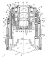
- FIG. 3 is a side sectional view showing a schematic configuration inside a lens barrel at a wide-angle end.
- FIG. 2 is a plan sectional view showing a schematic configuration inside a lens barrel at a wide-angle end.
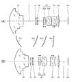
- FIG. 8 is a diagram illustrating a moving state of each lens group when a zoom operation is performed.
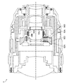
- FIG. 3 is a diagram showing a schematic configuration inside a lens barrel at a telephoto end.
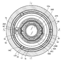
- FIG. 5 is a sectional view taken along line 5-5 of FIGS. 1 and 2.
- FIG. 6 is a sectional view taken along line 6-6 of FIGS. 1 and 2;
- FIG. 10 is a diagram illustrating a state in which the front holding frame of the third lens group is fixed by magnetic force.
- FIG. 4 is a side sectional view showing a schematic configuration inside a lens barrel in which a second lens group is a camera shake correction lens. It is a figure showing the modification of the state where the 3rd lens group front group holding frame is fixed by magnetic force.
- FIG. 3 is a block diagram illustrating an electrical configuration of the interchangeable lens. It is the perspective view which looked at the camera system from diagonally forward. It is a rear view of a camera main body.
- FIG. 1 is a side sectional view showing a schematic configuration inside the lens barrel at the wide angle end
- FIG. 2 is a plan sectional view showing a schematic configuration inside the lens barrel at the wide angle end.
- the interchangeable lens 1 is a so-called zoom lens, and mainly includes a lens barrel main body 10 to which a lens is assembled, and an exterior body 100 that covers the outer circumference of the lens barrel main body 10.
- the zoom ring 7 is connected to the cam barrel 14 by a connecting member (not shown), and by rotating the zoom ring 7, the cam barrel 14 rotates to change the focal length.
- the interchangeable lens 1 of the present embodiment has a manual focus adjustment function, and the focus can be manually adjusted by rotating a focus ring 8 provided on an outer peripheral portion thereof.
- the interchangeable lens 1 of the present embodiment has an aperture setting function manually, and the aperture can be manually set by rotating an aperture ring 9 provided on an outer peripheral portion thereof.
- the zoom ring 7, the focus ring 8, and the aperture ring 9 are examples of a plurality of operation rings.
- the lens barrel main body 10 has a fixed barrel 12 and a cam barrel 14.
- the cam cylinder 14 is fitted to the inner peripheral part of the fixed cylinder 12 and holds the inner peripheral part of the fixed cylinder 12 so as to be rotatable in the circumferential direction.
- the fixed cylinder 12 is an example of a fixed frame.
- the fixed cylinder 12 has a mount 16 at its base end (end on the image plane side).
- the mount 16 is constituted by a so-called bayonet mount.
- the mount 16 is attached to the base end of the fixed cylinder 12 by a plurality of mount fixing screws 18.
- the fixed cylinder 12 is configured such that the base end has the smallest outer diameter.
- the outer diameter of the mount 16 is equal to or less than the outer diameter of the base end of the fixed cylinder 12. More specifically, the outer diameter of the flange portion 16A having the largest outer diameter is equal to or less than the outer diameter of the base end of the fixed cylinder 12. In the present embodiment, the outer diameter of the flange portion 16 ⁇ / b> A is the same as the outer diameter of the base end of the fixed cylinder 12.
- a plurality of lenses are arranged inside the fixed barrel 12. Specifically, a first lens group G1, a second lens group G2, a third lens group G3, a fourth lens group G4, and a fifth lens group G5 are arranged in order from the object side along the optical axis Z. .
- Each lens group includes at least one lens.
- the first lens group G1, the second lens group G2, the third lens group G3, the fourth lens group G4, and the fifth lens group G5 are examples of an optical member, and the third lens group G3 is an example of a first optical member.
- the fourth lens group G4 is an example of a second optical member.
- ⁇ ⁇ Aperture St is arranged inside fixed cylinder 12.
- the stop St is disposed between the first lens group G1 and the second lens group G2.
- FIG. 3 is a diagram showing a moving state of each lens group when a zoom operation is performed.
- FIG. 4 is a side sectional view showing a schematic configuration inside the lens barrel at the telephoto end.
- 3A shows the lens arrangement at the wide-angle end
- FIG. 3B shows the lens arrangement at the telephoto end.
- the first lens group G1 to the fourth lens group G4 are lens groups that move with respect to the image plane Sim by a zoom operation.
- the fifth lens group G5 is a lens group fixed to the image plane Sim by a zoom operation.
- the first lens group G1 moves along a movement path AL1 by a zoom operation
- the second lens group G2 moves along a movement path AL2 by a zoom operation.
- the third lens group G3 moves along the movement path AL3 by the zoom operation
- the fourth lens group G4 moves along the movement path AL4 by the zoom operation.
- the stop St moves integrally with the second lens group G2.
- the third lens group G3 includes a front group G3a of the third lens group and a rear group G3b of the third lens group.
- the front group G3a of the third lens group is a lens group for correcting field curvature.
- the front group G3a of the third lens group is a lens group that can move independently of the other lens groups. When correcting the field curvature, the front group G3a of the third lens group is moved along the optical axis Z.
- the fourth lens group G4 is a lens group for focusing.
- the fourth lens group G4 is a lens group that can move independently of the other lens groups. When adjusting the focus, the fourth lens group G4 is moved along the optical axis Z.
- the first lens group holding frame 20 is provided with three first lens group driving cam pins 32 on the outer peripheral portion thereof.
- the three first lens group driving cam pins 32 are arranged at equal intervals in the circumferential direction.
- Each of the first lens group driving cam pins 32 is fitted into the first lens group driving cam groove 14A provided in the cam barrel 14 and the first lens group driving straight groove provided in the fixed barrel 12, respectively.
- the first lens group G1 is held in the fixed barrel 12.
- the cam barrel 14 is rotated, the first lens group G1 moves within the fixed barrel 12 along the optical axis Z.
- the second lens group G ⁇ b> 2 is held in the second lens group holding frame 22 and arranged in the fixed cylinder 12.
- the second lens group holding frame 22 is provided with three second lens group driving cam pins 34 on the outer peripheral portion thereof.
- the three second lens group driving cam pins 34 are arranged at equal intervals in the circumferential direction.
- the second lens group driving cam pins 34 are fitted in the second lens group driving cam grooves 14B provided in the cam barrel 14 and the second lens group driving straight grooves provided in the fixed barrel 12, respectively.
- the second lens group G2 is held in the fixed barrel 12.
- the cam barrel 14 is rotated, the second lens group G2 moves along the optical axis Z in the fixed barrel 12.
- an aperture unit 30 constituting the aperture St is assembled to the second lens group holding frame 22.
- the stop St is disposed in the fixed barrel 12 and moves together with the second lens group G2.
- the third lens group G ⁇ b> 3 is held in the third lens group holding frame 24 and arranged in the fixed cylinder 12.
- the third lens group holding frame 24 includes a third lens group rear group holding frame 24A and a third lens group front group holding frame 24B held on the inner peripheral portion of the third lens group rear group holding frame 24A. Is done.
- the third lens group front group holding frame 24B is held movably along the optical axis Z on the inner peripheral portion of the third lens group rear group holding frame 24A.
- the third lens group front group G3a is held by the third lens group front group holding frame 24B.
- the third lens group rear group G3b is held by the third lens group rear group holding frame 24A.
- FIG. 5 is a sectional view taken along line 5-5 of FIGS. 1 and 2.
- the third lens group rear group holding frame 24A is provided with three third lens group driving cam pins 36 on its outer peripheral portion.
- the three third lens group driving cam pins 36 are arranged at equal intervals in the circumferential direction.
- the third lens group driving cam pins 36 are fitted into the third lens group driving cam grooves 14C provided in the cam barrel 14 and the third lens group driving straight grooves 12C provided in the fixed barrel 12, respectively. .
- a first main shaft 48 and a first sub shaft 50 are provided on the inner peripheral portion of the third lens group rear group holding frame 24A.
- the first main shaft 48 and the first sub shaft 50 are arranged at positions facing each other with the optical axis Z interposed therebetween (arranged at intervals of 180 ° in the circumferential direction), and are arranged along the optical axis Z, respectively.
- the third lens group front group holding frame 24B is provided with a first main axis 48 and a first sub axis provided on the third lens group rear group holding frame 24A via the first main guide section 52 and the first sub guide section 54. 50 slidably supported. Thereby, the third lens group front group holding frame 24B is movably supported along the optical axis Z on the inner peripheral portion of the third lens group rear group holding frame 24A.
- the third lens group rear group holding frame 24A is an example of a first frame
- the third lens group front group holding frame 24B is an example of a first movable frame.
- the third lens group front group holding frame 24B is driven by the first motor 56, and moves along the optical axis Z along the inner periphery of the third lens group rear group holding frame 24A.
- the first motor 56 is constituted by a moving magnet type voice coil motor.
- the third lens group front group holding frame 24B is provided with a plurality of first magnets 56A and a plurality of inner yokes 56B of the voice coil motor constituting the first motor 56.
- the third lens group rear group holding frame 24A is provided with a first coil 56C of a voice coil motor constituting the first motor 56 and a plurality of outer yokes 56D.
- the first motor 56 is an example of a first driving unit.
- the third lens group G3 is held in the fixed barrel 12.
- the third lens group G3 moves along the optical axis Z in the fixed barrel 12 (the third lens group front group G3a and the third lens group rear group G3b are integrally formed). And moves within the fixed cylinder 12 along the optical axis Z.)
- the third lens group front group G3a moves alone along the optical axis Z (the third lens group front group G3a moves independently along the optical axis Z). .).
- the field curvature is corrected.
- the fourth lens group holding frame 26 includes a fourth lens group base holding frame 26A, and a fourth lens group movable holding frame 26B held on the inner periphery of the fourth lens group base holding frame 26A. .
- the fourth lens group movable holding frame 26B is supported movably along the optical axis Z on the inner peripheral portion of the fourth lens group base holding frame 26A.
- the fourth lens group G4 is held on the inner periphery of the fourth lens group movable holding frame 26B.
- FIG. 6 is a sectional view taken along line 6-6 in FIGS. 1 and 2.
- the fourth lens group base holding frame 26A is provided with three fourth lens group driving cam pins 38 on its outer peripheral portion.
- the three fourth lens group driving cam pins 38 are arranged at equal intervals in the circumferential direction.
- the fourth lens group driving cam pins 38 are fitted into the fourth lens group driving cam grooves 14D provided in the cam barrel 14 and the fourth lens group driving straight grooves 12D provided in the fixed barrel 12, respectively. .
- the fourth lens group base holding frame 26A is provided with a second main shaft 68 and a second sub shaft 70.
- the second main shaft 68 and the second sub shaft 70 are arranged at positions opposing each other across the optical axis Z (arranged at 180 ° intervals in the circumferential direction), and are arranged along the optical axis Z, respectively.
- the fourth lens group movable holding frame 26B is connected to the second main shaft 68 and the second sub shaft 70 provided on the fourth lens group base holding frame 26A via the second main guide portion 72 and the second sub guide portion 74. It is slidably supported. Thus, the fourth lens group movable holding frame 26B is movably supported along the optical axis Z on the inner peripheral portion of the fourth lens group base holding frame 26A.
- the fourth lens group base holding frame 26A is an example of a second frame
- the fourth lens group movable holding frame 26B is an example of a second movable frame.
- the fourth lens group movable holding frame 26B is driven by the second motor 58 as a focus motor, and moves along the optical axis Z along the inner periphery of the fourth lens group base holding frame 26A.
- the second motor 58 is constituted by a moving coil type voice coil motor.
- the fourth lens group movable holding frame 26B is provided with a plurality of second coils 58A of a voice coil motor constituting the second motor 58.
- the fourth lens group base holding frame 26A is provided with a plurality of second magnets 58B, a plurality of inner yokes 58C, and a plurality of outer yokes 58D of the voice coil motor constituting the second motor 58.
- the second motor 58 is an example of a second driving unit.
- the fourth lens group G4 is held in the fixed barrel 12.
- the fourth lens group G4 moves along the optical axis Z in the fixed barrel 12.
- the fourth lens group G4 moves independently along the optical axis Z.
- the focus adjustment is performed by independently moving the fourth lens group G4.
- the fourth lens group movable holding frame 26B has a balance weight 76 at a position opposite to the fourth lens group G4 in the direction of the optical axis Z. With the balance weight 76, the position of the center of gravity of the fourth lens group movable holding frame 26B and the fourth lens group G4 can be moved to the front end side (object side).
- the balance weight 76 can be provided by fitting the ring-shaped balance weight 76 to the object side of the cylindrical fourth lens group movable holding frame 26B.
- the fourth lens group movable holding frame 26B can be supported by the second main guide portion 72 and the second sub guide portion 74. The four-lens group movable holding frame 26B can be moved smoothly.
- the fifth lens group G ⁇ b> 5 is held in the fifth lens group holding frame 28 and arranged in the fixed cylinder 12.
- the fifth lens group holding frame 28 is attached to the fixed barrel 12 by a plurality of fifth lens group fixing screws.
- the lens barrel main body 10 is configured as described above.
- the first lens group G1, the second lens group G2, the third lens group G3, and the fourth lens group G4 move along the optical axis Z. Thereby, zooming is performed.
- the front group G3a of the third lens group moves independently along the optical axis Z.
- the interchangeable lens 1 corrects the curvature of field by independently moving the front group G3a of the third lens group.
- the fourth lens group movable holding frame 26B is a cylindrical body that holds the fourth lens group G4 on one end side (image side) and has a cavity on the other end side (object side).
- a part of the third lens group rear group holding frame 24A and a part of the third lens group front group holding frame 24B that hold the third lens group G3 are configured to be able to enter this cavity at the wide angle end.
- the lens barrel body 10 moves the third lens group G3 in a plane orthogonal to the optical axis. Thereby, the adjustment of the optical axis Z is performed.
- the third lens group G3 and the fourth lens group G4 in the interchangeable lens 1 are such that the third lens group G3 and the fourth lens group G4 are close at the wide angle end, and are close at the telephoto end. It will be the farthest away.
- the third lens group front group holding frame 24B is driven by a voice coil motor constituting the first motor 56. Therefore, when the power supply to the first coil 56C is stopped, the front lens group holding frame 24B of the third lens group can freely move within the range of the first main shaft 48 and the first sub shaft 50.
- the second motor 58 for driving the fourth lens group G4 is provided to fix the third lens group front group holding frame 24B in a state where the power supply to the first coil 56C is stopped.
- the front lens holding frame 24B of the third lens group is fixed using the magnetic material thus obtained.
- FIG. 7 is a diagram illustrating a state in which the third lens group front group holding frame is fixed at the wide angle end.
- the fixing of the third lens group front group holding frame 24B is performed by the magnetic force between the first magnet 56A of the first motor 56 and the inner yoke 58C and the outer yoke 58D, which are magnetic materials provided in the second motor 58. It is fixed by attracting.
- the first magnet 56A is provided on the third lens group front group holding frame 24B.
- the inner yoke 58C and the outer yoke 58D are provided on the fourth lens group base holding frame 26A, and the fourth lens group base holding frame 26A is held by the cam barrel 14.
- the third lens group front group holding frame 24B is fixed to the fourth lens group base holding frame 26A and the cam barrel 14.
- the third lens group G3 and the fourth lens group G4 come close to each other. That is, as shown in FIG. 6, the first magnet 56A provided in the third lens group front group holding frame 24B and the inner yoke 58C and the outer yoke 58D of the second motor 58 are arranged close to each other.
- the front frame holding frame 24B of the third lens group is disposed at the moving end that does not move to the image plane side. Therefore, before the energization of the first coil 56C is stopped, the arrangement of the lens groups is moved so that the arrangement of the lens groups is at the wide-angle end as shown in FIG.
- the third lens group front group holding frame 24B cannot move to the image plane side of the interchangeable lens 1.
- the third lens group front group holding frame 24B is positioned on the object side of the interchangeable lens 1. Also does not move. Therefore, the third lens group front group holding frame 24B can be fixed in the interchangeable lens 1.
- the plurality of first magnets 56A are preferably arranged symmetrically with respect to the center of the third lens group front group holding frame 24B. Since the third lens group front group holding frame 24B is formed of a cylindrical body, any one of the first magnets 56A, the inner yoke 58C, and the outer yoke 58D can be formed by symmetrically arranging the plurality of first magnets 56A. It can be securely approached and can be fixed by magnetic force.
- the balance weight 76 of the fourth lens group movable holding frame 26B and the first magnet 56A of the third lens group front group holding frame 24B can be attracted by magnetic force. It can. Thereby, the fourth lens group movable holding frame 26B can be fixed to the third lens group front group holding frame 24B fixed to the inner yoke 58C and the outer yoke 58D, and the fourth lens group movable holding frame 26B moves. Can be prevented.
- a magnetic material used for the balance weight 76 iron, cobalt, nickel, or an alloy thereof can be used.
- FIG. 8 is a side cross-sectional view showing a schematic configuration inside a lens barrel of an embodiment in which the second lens group G2 of the above embodiment is a lens for camera shake correction.
- the second lens group (lens for correcting camera shake) G2 is held by the lens holding frame 82 for correcting camera shake and arranged in the fixed barrel 12.
- the camera shake correction lens holding frame 82 includes a camera shake correction lens base holding frame 82A, and a camera shake correction lens movable holding frame 82B held on the inner periphery of the camera shake correction lens base holding frame 82A.
- the second lens group (camera shake correction lens) G2 is held on the inner peripheral portion of the camera shake correction lens movable holding frame 82B.
- the camera shake correction lens base holding frame 82A is an example of a second frame
- the camera shake correction lens movable holding frame 82B is an example of a second movable frame.
- the second lens group (lens for camera shake correction) G2 is an example of a second optical member.
- the camera shake correction lens base holding frame 82A is provided with three camera shake correction lens driving cam pins 84 on the outer peripheral portion thereof.
- the three camera shake correcting lens driving cam pins 84 are arranged at equal intervals in the circumferential direction.
- Each of the camera shake correction lens driving cam pins 84 is provided. Each of them is fitted into a camera shake correction lens driving cam groove 14E provided in the cam barrel 14 and a camera shake correction lens driving straight groove provided in the fixed barrel 12.
- the diaphragm unit 30 that forms the diaphragm St is attached to the camera shake correction lens holding frame 82.
- the camera-shake correction lens base holding frame 82A and the camera-shake correction lens movable holding frame 82B are three steel balls 86 arranged at equal intervals in the circumferential direction on the inner periphery of the camera-shake correction lens base holding frame 82A. And are supported by four springs 88. Further, the camera shake correction lens movable holding frame 82B is driven by an unillustrated X-axis motor and Y-axis motor 90, and is movable in a direction orthogonal to the optical axis Z.
- the spring 88 is an urging member for urging the camera shake correction lens movable holding frame 82B with respect to the camera shake correction lens base holding frame 82A with the steel ball 86 interposed therebetween.
- the Y-axis motor 90 is constituted by a moving coil type voice coil motor.
- the camera shake correction lens movable holding frame 82B is provided with a coil 90C of a voice coil motor constituting the Y-axis motor 90.
- the camera shake correction lens base holding frame 82A is provided with a magnet 90A of a voice coil motor constituting the Y-axis motor 90 and yokes 90B and 90D.
- An X-axis motor (not shown) is similarly configured.
- the X-axis motor and the Y-axis motor 90 are an example of a second driving unit.
- the second lens group (camera shake correction lens) G2 is held in the fixed barrel 12.
- the second lens group (lens for correcting camera shake) G2 moves in the direction perpendicular to the optical axis Z.
- FIG. 9 is a diagram illustrating a state in which the front holding frame of the third lens group is fixed to the lens base holding frame for camera shake correction.
- the second lens group G2 includes an X-axis motor and a Y-axis motor 90 for moving the camera shake correction lens by using a camera shake correction lens as described above.
- the third lens group front group holding frame 24B is fixed to the third lens group front group holding frame 24B using a magnetic body provided on the X-axis motor and the Y-axis motor 90.
- the fixing of the third lens group front group holding frame 24 ⁇ / b> B is performed between the first magnet 56 ⁇ / b> A of the first motor 56 and the yoke 90 ⁇ / b> B which is a magnetic material provided in the Y-axis motor 90. It is fixed by attracting by the magnetic force of.
- the yoke 90B is provided on a camera shake correction lens base holding frame 82A, and the camera shake correction lens base holding frame 82A is held by the cam barrel 14.
- the third lens group front group holding frame 24B is fixed to the camera shake correction lens base holding frame 82A and the cam barrel 14.
- the power supply to the first motor 56 to the first coil 56C is stopped before the third lens group is stopped.
- the power supply to the first coil 56C is stopped in a state where the group holding frame 24B is arranged at the distal end side in the interchangeable lens 1, that is, at the moving end where the third lens group front group holding frame 24B does not move toward the distal end side. .
- the magnetic force between the first magnet 56A of the first motor 56 and the yoke 90B of the camera-shake correction lens base holding frame 82A can attract each other.
- the movement of the group holding frame 24B can be prevented and the group holding frame 24B can be fixed in the interchangeable lens 1.
- FIG. 10 is a block diagram showing an electrical configuration of the interchangeable lens.
- the interchangeable lens 1 includes a third lens group front group drive section 210 that drives the third lens group front group G3a, a third lens group front group position detection section 212 that detects the position of the third lens group front group G3a, and a fourth The fourth lens group driving unit 214 for driving the lens group G4, the fourth lens group position detecting unit 216 for detecting the position of the fourth lens group G4, the diaphragm driving unit 218 for driving the diaphragm St, and the temperature in the interchangeable lens 1
- a temperature control unit 220 for detecting a focus operation, a focus operation detection unit 222 for detecting a focus operation, a zoom setting detection unit 224 for detecting a zoom operation, an aperture setting detection unit 226 for detecting an aperture operation, and overall control of the entire operation of the interchangeable lens 1.
- a lens control unit 228 that performs the operation.
- the third lens group front group drive section 210 includes the first motor 56 and its drive circuit.
- the third lens group front group drive section 210 drives the first motor 56 in response to a command from the lens control section 228 to move the third lens group front group G3a along the optical axis Z.
- the third lens group front group position detection unit 212 includes a position detection sensor (not shown).
- the position detection sensor is configured by a magnetic sensor such as a Hall element or a magneto-resistive element (Magneto-Resistive-Sensor).
- the third lens group front group position detection unit 212 detects the position of the third lens group front group G3a with a position detection sensor, and outputs the detection result to the lens control unit 228.
- the position of the third lens group front group G3a is a position with respect to the third lens group rear group G3b, and is a position in the third lens group rear group holding frame 24A.
- the fourth lens group driving unit 214 includes the second motor 58 and a driving circuit thereof.
- the fourth lens group drive unit 214 drives the second motor 58 in response to a command from the lens control unit 228 to move the fourth lens group G4 along the optical axis Z.
- the fourth lens group position detecting section 216 includes a position detecting sensor (not shown).
- the position detection sensor is composed of, for example, a magnetic sensor such as a Hall element or a magnetoresistive element.
- the fourth lens group position detector 216 detects the position of the fourth lens group G4 with a position sensor, and outputs the detection result to the lens controller 228.
- the position of the fourth lens group G4 is a position in the fourth lens group holding frame 26.
- the aperture drive unit 218 includes an aperture motor and a drive circuit therefor.
- An aperture motor (not shown) is provided in the aperture unit 30.
- the aperture driving unit 218 drives an aperture motor in response to a command from the lens control unit 228 to open and close the aperture St.
- the temperature detection unit 220 includes a temperature sensor (not shown).
- the temperature sensor is provided in the aperture unit 30, for example.
- Temperature detecting section 220 detects the temperature in interchangeable lens 1 with a temperature sensor, and outputs the detection result to lens control section 228.
- the focus operation detection unit 222 detects the amount of rotation operation of the focus ring 8 and outputs the detection result to the lens control unit 228.
- the lens control unit 228 detects a focus operation amount based on an output from the focus operation detection unit 222.
- the zoom setting detection unit 224 detects the setting position of the zoom ring 7 and outputs the detection result to the lens control unit 228.
- the lens control unit 228 detects a zoom set value (focal length) based on the output from the zoom setting detection unit 224.
- the aperture setting detector 226 detects the set position of the aperture ring 9 and outputs the detection result to the lens controller 228.
- the lens control unit 228 detects a set value of the aperture (aperture value) based on an output from the aperture setting detection unit 226.
- the lens control unit 228 controls the operation of each unit based on the operation of the focus ring 8, the zoom ring 7, and the aperture ring 9. Specifically, when the manual focus is set, the fourth lens group drive unit 214 is driven based on the rotation amount of the focus ring 8 to move the fourth lens group G4. Further, based on the setting of the zoom ring 7, the third lens group front group driving unit 210 and the fourth lens group driving unit 214 are driven to move the third lens group front group G3a and the fourth lens group G4 to predetermined positions. Let it. Further, the aperture driving unit 218 is driven based on the setting of the aperture ring 9, and the aperture St is set to a predetermined aperture (aperture value).
- the lens control unit 228 controls the operation of each unit according to a command from the camera on which the interchangeable lens 1 is mounted.
- the fourth lens group driving unit 214 is driven based on autofocus information from the camera to move the fourth lens group G4 to a predetermined position.
- the aperture driving unit 218 is driven based on the aperture setting information from the camera, and the aperture St is set to a predetermined opening amount.
- the lens control unit 228 communicates with the camera control unit 230 of the camera, and receives a drive command for each unit from the camera control unit 230.
- the camera control unit 230 transmits zoom setting information, aperture setting information, focus position information, and the like. Communication between the lens control unit 228 and the camera control unit 230 is performed via a terminal 16 ⁇ / b> B provided on the mount 16.
- the lens control section 228 drives the third lens group front group drive section 210 based on the temperature detected by the temperature detection section 220 to move the third lens group front group G3a to a predetermined position.
- the lens control unit 228 is configured by, for example, a computer having a CPU (Central Processing Unit), a ROM (Read Only Memory), and a RAM (Random Access Memory), and by executing a predetermined program. And implement various control functions.
- a computer having a CPU (Central Processing Unit), a ROM (Read Only Memory), and a RAM (Random Access Memory), and by executing a predetermined program. And implement various control functions.
- a CPU Central Processing Unit
- ROM Read Only Memory
- RAM Random Access Memory
- FIG. 11 and FIG. 12 are external views showing an example of the configuration of a camera system using the lens barrel of the present embodiment as an example of an imaging apparatus.
- FIG. 11 is a perspective view of the camera system as viewed obliquely from the front
- FIG. 12 is a rear view of the camera body.
- the camera system 110 is a mirrorless digital single-lens camera or a digital single-lens reflex camera comprising the interchangeable lens 1 and a camera body 150 to which the interchangeable lens 1 is detachable.
- the imaging device is not limited to the camera system shown in FIGS. 11 and 12, and it goes without saying that a mirrorless digital single-lens camera or a digital single-lens reflex camera in which a lens and a camera body are integrally formed may be used. .
- a body mount 160 on which the interchangeable lens 1 is mounted, a finder window 120 of an optical finder, and the like are provided.
- a shutter release button 122, a shutter speed dial 123, An exposure compensation dial 124, a power lever 125, and a built-in flash 130 are provided.
- a monitor 116, an eyepiece 126 of an optical finder, a MENU and OK key 127, a cross key 128, a play button 129, and the like are mainly provided on the rear surface of the camera body 150.
- the monitor 116 displays a live view image in the imaging mode, reproduces and displays an image captured in the reproduction mode, and functions as a display unit for displaying various menu screens.
- An MENU and OK key 127 is an operation key having both a function as a menu button for issuing a command to display a menu on the screen of the monitor 116 and a function as an OK button for instructing selection and execution of the selected contents. It is.
- the cross key 128 is an operation unit for inputting four directions of up, down, left, and right, and functions as a button for selecting an item from a menu screen or instructing selection of various setting items from each menu.
- the up key and the down key of the cross key 128 function as a zoom switch at the time of image capturing or a reproduction zoom switch at the time of the reproduction mode.
- Function as The playback button 129 is a button for switching to a playback mode in which a captured still image or a moving image is displayed on the monitor 116.
- the third lens group front group holding frame is used when the lens barrel and the imaging device are transported in a state where the power is turned off. Since movement of 24B can be prevented, breakage of the optical member can be prevented.
Abstract
Provided are a lens barrel and an image capturing device which are configured so that a movable frame can be affixed to a stationary frame without providing a member for affixing the movable member. This lens barrel is provided with: a first magnet (56A) provided to a third lens group front group holding frame (24B); a first motor (56) for driving the third lens group front group holding frame (24B) by means of a first coil (56C); a second coil (58A) provided to a fourth lens group movable holding frame (26B); and a second motor (58) for driving the fourth lens group movable holding frame (26B) by means of a second magnet (58B) provided to a fourth lens group base holding frame (26A) affixed to a stationary cylinder (12) and a cam cylinder (14). When the supply of electricity to the first coil (56C) is stopped, the third lens group front group holding frame (24B) is affixed by magnetic force acting between the first magnet (56A), and an inner yoke (58C) and an outer yoke (58D), the inner and outer yokes (58C, 58D) being provided to the fourth lens group base holding frame (26A).
Description
本発明は、レンズ鏡筒及び撮像装置に係り、特に、電源オフ時に、レンズ鏡筒内の可動部材を固定して保持するレンズ鏡筒及び撮像装置に関する。
The present invention relates to a lens barrel and an imaging device, and more particularly, to a lens barrel and an imaging device that fix and hold a movable member in the lens barrel when power is turned off.
撮像装置の電源がオフ状態のときに、撮像装置内の可動部材を固定して保持させることで、可動部材が不用意に移動することを抑制している。
(4) When the power supply of the imaging device is off, the movable member in the imaging device is fixed and held, thereby preventing the movable member from being accidentally moved.
例えば、下記の特許文献1には、レンズ鏡筒本体にロック用磁石を、レンズホルダにロック用磁性体を有し、電源オフ時に、レンズホルダをレンズ鏡筒本体に固定保持するレンズ鏡筒が記載されている。
For example, Patent Literature 1 below discloses a lens barrel that has a locking magnet in a lens barrel main body, a locking magnetic body in a lens holder, and holds the lens holder in the lens barrel main body when power is turned off. Has been described.
近年、デジタルスチルカメラやデジタルビデオムービーに代表されるデジタル撮像装置のコンパクト化やモバイル化に伴い、レンズとそれを駆動するアクチュエータの小型化が進んでいる。特許文献1のレンズ鏡筒においては、可動部材を固定するために、ロック用磁石及びロック用磁性体を設ける必要があり、さらなる小型化が望まれていた。
レ ン ズ In recent years, as digital imaging devices typified by digital still cameras and digital video movies have become more compact and mobile, lenses and actuators for driving the lenses have been reduced in size. In the lens barrel of Patent Literature 1, it is necessary to provide a locking magnet and a locking magnetic body in order to fix the movable member, and further miniaturization has been desired.
本発明は、このような事情に鑑みてなされたものであり、可動部材を固定するための部材を設けることなく、可動部材を固定枠に固定することができるレンズ鏡筒及び撮像装置を提供する。
The present invention has been made in view of such circumstances, and provides a lens barrel and an imaging device that can fix a movable member to a fixed frame without providing a member for fixing the movable member. .
本発明の目的を達成するために、本発明に係るレンズ鏡筒は、固定枠と、第1光学部材を保持し、第1光学部材の光軸方向に沿って固定枠に移動自在に支持された第1可動枠と、第1可動枠に第1マグネットが配設され、固定枠に第1コイルが配設され、第1可動枠を第1光学部材の光軸方向に移動させる第1駆動部と、第2光学部材を保持し、第2光学部材の光軸方向又は光軸と直交する方向に沿って、固定枠に移動自在に支持された第2可動枠と、第2可動枠に第2コイルが配設され、固定枠に第2マグネットが配設され、第2可動枠を第2光学部材の光軸方向又は光軸と直交する方向に移動させる第2駆動部と、を備え、第1可動枠は、第2駆動部に近接する移動端に移動し、かつ第1コイルへの通電が停止されると、第1マグネットと第2駆動部の磁性体との間の磁力により移動端に固定される。
In order to achieve the object of the present invention, a lens barrel according to the present invention holds a fixed frame and a first optical member, and is movably supported by the fixed frame along the optical axis direction of the first optical member. A first movable frame, a first magnet provided on the first movable frame, a first coil provided on the fixed frame, and a first drive for moving the first movable frame in the optical axis direction of the first optical member. And a second movable frame that holds the second optical member and is movably supported by a fixed frame along the optical axis direction of the second optical member or in a direction perpendicular to the optical axis. A second drive unit provided with a second coil, a second magnet provided on the fixed frame, and a second movable unit configured to move the second movable frame in an optical axis direction of the second optical member or in a direction orthogonal to the optical axis. The first movable frame moves to a moving end close to the second drive unit, and when the power supply to the first coil is stopped, the first magnetic frame moves. Once fixed to the movable end by the magnetic force between the magnetic body of the second driving unit.
本発明によれば、第1可動枠に設けられた第1マグネットと、第2駆動部に設けられた磁性体とを、第1コイルへの通電を停止、すなわち、電源をOFF状態にした時、第1マグネットと第2駆動部の磁性体との間の磁力により、第1可動枠を移動端に固定することができる。したがって、電源がOFFになっても第1可動枠が固定枠内で移動することを防止することができ、電源OFF時に、第1可動枠が動くことで、光学部材が飛び出すことを防止することができる。
According to the present invention, when the power supply to the first coil is stopped, that is, when the power is turned off, the first magnet provided on the first movable frame and the magnetic body provided on the second drive unit are stopped. The first movable frame can be fixed to the movable end by the magnetic force between the first magnet and the magnetic body of the second drive unit. Therefore, it is possible to prevent the first movable frame from moving within the fixed frame even when the power is turned off, and to prevent the optical member from jumping out by moving the first movable frame when the power is turned off. Can be.
本発明の一態様は、第1駆動部は、ムービングマグネット型のボイスコイルモータであり、第2駆動部は、ムービングコイル型のボイスコイルモータであることが好ましい。
In one embodiment of the present invention, it is preferable that the first driver is a moving magnet type voice coil motor and the second driver is a moving coil type voice coil motor.
この態様によれば、第2駆動部をムービングコイル型のボイスコイルモータとすることで、マグネットよりコイルの方が軽いため、第2可動枠の移動を滑らかに行うことができる。また、第1駆動部をムービングマグネット型のボイスコイルモータとすることで、レンズ鏡筒を小型化することができる。
According to this aspect, since the second driving unit is a moving coil type voice coil motor, the coil is lighter than the magnet, so that the second movable frame can be moved smoothly. Further, by using the moving magnet type voice coil motor as the first drive unit, the lens barrel can be downsized.
本発明の一態様は、第2駆動部の磁性体は、第2マグネットが固定されるヨークであることが好ましい。
According to one embodiment of the present invention, it is preferable that the magnetic body of the second drive unit is a yoke to which the second magnet is fixed.
この態様によれば、第2駆動部の磁性体として、第2マグネットが固定されるヨークとすることで、別途、固定する部材を設けることなく、第1可動部の固定を行うことができる。
According to this aspect, by using a yoke to which the second magnet is fixed as the magnetic body of the second drive section, the first movable section can be fixed without providing a separate fixing member.
本発明の一態様は、第2可動枠は、第2光学部材の光軸方向に沿って固定枠に移動自在に支持され、かつ第1可動枠側に空洞を有する筒体であり、第1可動枠は、第2駆動部に近接する移動端に移動すると、第1可動枠の空洞に進入することが好ましい。
In one aspect of the present invention, the second movable frame is a cylindrical body that is movably supported by the fixed frame along the optical axis direction of the second optical member and has a cavity on the first movable frame side. It is preferable that the movable frame enters the cavity of the first movable frame when the movable frame moves to the moving end close to the second drive unit.
この態様によれば、第2可動枠の第1可動枠側に空洞を有し、第1可動枠をこの空洞に進入させることができる。したがって、第1可動枠に設けられた光学部材と、第2可動枠に設けられた光学部材とを、近接させることができる。
According to this aspect, the second movable frame has a cavity on the first movable frame side, and the first movable frame can enter this cavity. Therefore, the optical member provided on the first movable frame can be brought close to the optical member provided on the second movable frame.
本発明の一態様は、第2可動枠は、第2光学部材の光軸と直交する方向に沿って固定枠に移動自在に支持され、第2光学部材は、手振れ補正用のレンズであることが好ましい。
In one embodiment of the present invention, the second movable frame is movably supported by the fixed frame along a direction perpendicular to the optical axis of the second optical member, and the second optical member is a lens for camera shake correction. Is preferred.
この態様によれば、手振れ補正用のレンズを駆動させるために配置される磁性体と、第1可動枠に配設された第1マグネットと、を固定することで、第1可動枠を固定することができる。
According to this aspect, the first movable frame is fixed by fixing the magnetic body disposed to drive the camera shake correction lens and the first magnet disposed on the first movable frame. be able to.
本発明の一態様は、第1可動枠は筒体であり、複数の第1マグネットが、第1可動枠の中心に対して対称に配設されていることが好ましい。
In one embodiment of the present invention, it is preferable that the first movable frame is a cylindrical body, and the plurality of first magnets are symmetrically disposed with respect to the center of the first movable frame.
この態様によれば、第1マグネットを第1可動枠の中心に対して、対称に配設することで、複数の第1マグネットのいずれかを、第2駆動部の磁性体に近付けることができ、第1マグネットと第2駆動部の磁性体との間で第1可動枠を固定することができる。
According to this aspect, by disposing the first magnet symmetrically with respect to the center of the first movable frame, any one of the plurality of first magnets can be brought closer to the magnetic body of the second drive unit. The first movable frame can be fixed between the first magnet and the magnetic body of the second drive unit.
本願の一態様は、第2可動枠の第1可動枠側にバランスウエイトを有し、バランスウエイトは、磁性体で形成されており、第1コイルへの通電が停止されると、第1マグネットと、バランスウエイトとの間の磁力により第2可動枠が固定されることが好ましい。
One aspect of the present application has a balance weight on the first movable frame side of the second movable frame, and the balance weight is formed of a magnetic material, and when energization of the first coil is stopped, the first magnet is turned off. It is preferable that the second movable frame is fixed by a magnetic force between the second movable frame and the balance weight.
この態様によれば、第2可動枠の第1可動枠側にバランスウエイトを有することで、第2可動枠の重心を第1可動枠側に移動させることができる。したがって、第2可動枠の移動を安定して行うことができる。また、バランスウエイトを磁性体とすることで、第2可動枠のバランスウエイトと、第1可動枠の第1マグネットと、を固定することができる。これにより、第1可動枠を固定枠に固定することができるとともに、固定された第1可動枠に第2可動枠を固定させることができる。
According to this aspect, by having the balance weight on the first movable frame side of the second movable frame, the center of gravity of the second movable frame can be moved to the first movable frame side. Therefore, the movement of the second movable frame can be performed stably. Further, by using a balance weight of a magnetic material, the balance weight of the second movable frame and the first magnet of the first movable frame can be fixed. Thus, the first movable frame can be fixed to the fixed frame, and the second movable frame can be fixed to the fixed first movable frame.
本願の一態様は、固定枠は、第1可動枠を支持する第1枠体と、第2可動枠を支持する第2枠体と、からなることが好ましい。
In one aspect of the present application, the fixed frame preferably includes a first frame supporting the first movable frame and a second frame supporting the second movable frame.
この態様によれば、固定枠を第1枠体と第2枠体とから構成することで、それぞれの第1枠体及び第2枠体に対して、第1可動枠及び第2可動枠を移動させることができるので、第1可動枠及び第2可動枠の移動距離を調整することができる。
According to this aspect, by configuring the fixed frame from the first frame and the second frame, the first movable frame and the second movable frame are respectively provided for the first frame and the second frame. Since it can be moved, the moving distance of the first movable frame and the second movable frame can be adjusted.
本発明の目的を達成するために、本発明に係る撮像装置は、上記記載のレンズ鏡筒を備える。
In order to achieve the object of the present invention, an imaging device according to the present invention includes the above-described lens barrel.
本発明によれば、上記記載のレンズ鏡筒を備えることで、電源OFF時に、第1可動枠を固定することができる。したがって、光学部材の破損等を防止することができる。
According to the present invention, by providing the lens barrel described above, the first movable frame can be fixed when the power is turned off. Therefore, breakage of the optical member can be prevented.
本発明のレンズ鏡筒によれば、第1コイルへの通電を停止した際に、第1マグネットと、第2駆動部の磁性体と、を磁力により引き合わせることができるので、第1可動枠を固定枠に固定することができる。したがって、レンズ鏡筒及び撮像装置の運搬時に第1可動枠が移動することを防止することができ、光学部材の破損等を防止することができる。
According to the lens barrel of the present invention, when the power supply to the first coil is stopped, the first magnet and the magnetic body of the second drive unit can be attracted to each other by the magnetic force. Can be fixed to a fixed frame. Therefore, it is possible to prevent the first movable frame from moving when the lens barrel and the imaging device are carried, and to prevent damage to the optical member.
以下、添付図面にしたがって、本発明に係るレンズ鏡筒、及び、撮像装置について説明する。
Hereinafter, the lens barrel and the imaging device according to the present invention will be described with reference to the accompanying drawings.
[レンズ鏡筒の構成]
ここでは、本実施形態のレンズ鏡筒をレンズ交換式カメラの交換レンズに適用した場合を例に説明する。図1は、広角端におけるレンズ鏡筒の内部の概略構成を示す側面断面図であり、図2は、広角端におけるレンズ鏡筒の内部の概略構成を示す平面断面図である。 [Configuration of lens barrel]
Here, an example in which the lens barrel of the present embodiment is applied to an interchangeable lens of a lens interchangeable camera will be described. FIG. 1 is a side sectional view showing a schematic configuration inside the lens barrel at the wide angle end, and FIG. 2 is a plan sectional view showing a schematic configuration inside the lens barrel at the wide angle end.
本実施の形態の交換レンズ1は、いわゆるズームレンズであり、主として、レンズが組み付けられた鏡胴本体10と、鏡胴本体10の外周を覆う外装体100と、で構成される。外装体100の外周部に備えられたズームリング7を回転操作することにより、焦点距離が連続的に変化する。ズームリング7は、不図示の連結部材によりカム筒14とで連結され、ズームリング7を回転操作することで、カム筒14が回転し、焦点距離を変化させる。
The interchangeable lens 1 according to the present embodiment is a so-called zoom lens, and mainly includes a lens barrel main body 10 to which a lens is assembled, and an exterior body 100 that covers the outer circumference of the lens barrel main body 10. By rotating the zoom ring 7 provided on the outer peripheral portion of the exterior body 100, the focal length changes continuously. The zoom ring 7 is connected to the cam barrel 14 by a connecting member (not shown), and by rotating the zoom ring 7, the cam barrel 14 rotates to change the focal length.
また、本実施の形態の交換レンズ1は、マニュアルによる焦点調節機能を有し、その外周部に備えられたフォーカスリング8を回転操作することにより、マニュアルで焦点調節が可能とされている。更に、本実施の形態の交換レンズ1は、マニュアルにより絞り設定機能を有し、その外周部に備えられた絞りリング9を回転操作することにより、マニュアルでの絞りの設定が可能とされている。ズームリング7、フォーカスリング8及び絞りリング9は、複数の操作リングの一例である。
In addition, the interchangeable lens 1 of the present embodiment has a manual focus adjustment function, and the focus can be manually adjusted by rotating a focus ring 8 provided on an outer peripheral portion thereof. Further, the interchangeable lens 1 of the present embodiment has an aperture setting function manually, and the aperture can be manually set by rotating an aperture ring 9 provided on an outer peripheral portion thereof. . The zoom ring 7, the focus ring 8, and the aperture ring 9 are examples of a plurality of operation rings.
≪鏡胴本体≫
図1及び図2に示すように、鏡胴本体10は、固定筒12及びカム筒14を有する。カム筒14は、固定筒12の内周部に嵌合されて、固定筒12の内周部を周方向に回転自在に保持される。固定筒12は、固定枠の一例である。 ≪Main body 胴
As shown in FIGS. 1 and 2, the lens barrelmain body 10 has a fixed barrel 12 and a cam barrel 14. The cam cylinder 14 is fitted to the inner peripheral part of the fixed cylinder 12 and holds the inner peripheral part of the fixed cylinder 12 so as to be rotatable in the circumferential direction. The fixed cylinder 12 is an example of a fixed frame.
図1及び図2に示すように、鏡胴本体10は、固定筒12及びカム筒14を有する。カム筒14は、固定筒12の内周部に嵌合されて、固定筒12の内周部を周方向に回転自在に保持される。固定筒12は、固定枠の一例である。 ≪Main body 胴
As shown in FIGS. 1 and 2, the lens barrel
固定筒12は、その基端部(像面側の端部)にマウント16を有する。マウント16は、いわゆるバヨネットマウントで構成される。マウント16は、複数のマウント固定用ねじ18によって、固定筒12の基端部に取り付けられる。
The fixed cylinder 12 has a mount 16 at its base end (end on the image plane side). The mount 16 is constituted by a so-called bayonet mount. The mount 16 is attached to the base end of the fixed cylinder 12 by a plurality of mount fixing screws 18.
図1及び図2に示すように、固定筒12は、基端部が最も外径の小さな部位として構成される。マウント16は、その外径が、固定筒12の基端部の外径以下とされる。より具体的には、最も外径の大きなフランジ部16Aの外径が、固定筒12の基端部の外径以下とされる。本実施の形態では、フランジ部16Aの外径が、固定筒12の基端部の外径と同じ外径で構成されている。
As shown in FIGS. 1 and 2, the fixed cylinder 12 is configured such that the base end has the smallest outer diameter. The outer diameter of the mount 16 is equal to or less than the outer diameter of the base end of the fixed cylinder 12. More specifically, the outer diameter of the flange portion 16A having the largest outer diameter is equal to or less than the outer diameter of the base end of the fixed cylinder 12. In the present embodiment, the outer diameter of the flange portion 16 </ b> A is the same as the outer diameter of the base end of the fixed cylinder 12.
<レンズ構成>
固定筒12の内部には、複数のレンズが配置される。具体的には、光軸Zに沿って、物体側から順に、第1レンズ群G1、第2レンズ群G2、第3レンズ群G3、第4レンズ群G4及び第5レンズ群G5が配置される。各レンズ群は、少なくとも1枚のレンズで構成される。第1レンズ群G1、第2レンズ群G2、第3レンズ群G3、第4レンズ群G4及び第5レンズ群G5は、光学部材の一例であり、第3レンズ群G3が第1光学部材の一例であり、第4レンズ群G4が第2光学部材の一例である。 <Lens configuration>
A plurality of lenses are arranged inside the fixedbarrel 12. Specifically, a first lens group G1, a second lens group G2, a third lens group G3, a fourth lens group G4, and a fifth lens group G5 are arranged in order from the object side along the optical axis Z. . Each lens group includes at least one lens. The first lens group G1, the second lens group G2, the third lens group G3, the fourth lens group G4, and the fifth lens group G5 are examples of an optical member, and the third lens group G3 is an example of a first optical member. And the fourth lens group G4 is an example of a second optical member.
固定筒12の内部には、複数のレンズが配置される。具体的には、光軸Zに沿って、物体側から順に、第1レンズ群G1、第2レンズ群G2、第3レンズ群G3、第4レンズ群G4及び第5レンズ群G5が配置される。各レンズ群は、少なくとも1枚のレンズで構成される。第1レンズ群G1、第2レンズ群G2、第3レンズ群G3、第4レンズ群G4及び第5レンズ群G5は、光学部材の一例であり、第3レンズ群G3が第1光学部材の一例であり、第4レンズ群G4が第2光学部材の一例である。 <Lens configuration>
A plurality of lenses are arranged inside the fixed
また、固定筒12の内部には、絞りStが配置される。絞りStは、第1レンズ群G1と第2レンズ群G2との間に配置される。
絞 り Aperture St is arranged inside fixed cylinder 12. The stop St is disposed between the first lens group G1 and the second lens group G2.
図3は、ズーム操作した場合の各レンズ群の移動状態を示す図である。図4は、望遠端におけるレンズ鏡筒の内部の概略構成を示す側面断面図である。図3において、(A)は、広角端でのレンズ配置を示しており、(B)は、望遠端でのレンズ配置を示している。
FIG. 3 is a diagram showing a moving state of each lens group when a zoom operation is performed. FIG. 4 is a side sectional view showing a schematic configuration inside the lens barrel at the telephoto end. 3A shows the lens arrangement at the wide-angle end, and FIG. 3B shows the lens arrangement at the telephoto end.
図3に示すように、第1レンズ群G1から第4レンズ群G4は、ズーム操作により、像面Simに対して移動するレンズ群である。第5レンズ群G5は、ズーム操作により、像面Simに対して固定のレンズ群である。第1レンズ群G1は、ズーム操作により移動軌跡AL1に沿って移動し、第2レンズ群G2は、ズーム操作により移動軌跡AL2に沿って移動する。また、第3レンズ群G3は、ズーム操作により移動軌跡AL3に沿って移動し、第4レンズ群G4は、ズーム操作により移動軌跡AL4に沿って移動する。絞りStは、第2レンズ群G2と一体的に移動する。
As shown in FIG. 3, the first lens group G1 to the fourth lens group G4 are lens groups that move with respect to the image plane Sim by a zoom operation. The fifth lens group G5 is a lens group fixed to the image plane Sim by a zoom operation. The first lens group G1 moves along a movement path AL1 by a zoom operation, and the second lens group G2 moves along a movement path AL2 by a zoom operation. Further, the third lens group G3 moves along the movement path AL3 by the zoom operation, and the fourth lens group G4 moves along the movement path AL4 by the zoom operation. The stop St moves integrally with the second lens group G2.
図3に示すように、第3レンズ群G3は、第3レンズ群前群G3a及び第3レンズ群後群G3bで構成される。第3レンズ群前群G3aは、像面湾曲補正用のレンズ群である。第3レンズ群前群G3aは、他のレンズ群とは独立して移動可能なレンズ群である。像面湾曲を補正する場合は、この第3レンズ群前群G3aを光軸Zに沿って移動させる。
As shown in FIG. 3, the third lens group G3 includes a front group G3a of the third lens group and a rear group G3b of the third lens group. The front group G3a of the third lens group is a lens group for correcting field curvature. The front group G3a of the third lens group is a lens group that can move independently of the other lens groups. When correcting the field curvature, the front group G3a of the third lens group is moved along the optical axis Z.
また、第4レンズ群G4は、焦点調節用のレンズ群である。第4レンズ群G4は、他のレンズ群とは独立して移動可能なレンズ群である。焦点調節する場合は、この第4レンズ群G4を光軸Zに沿って移動させる。
{Circle around (4)} The fourth lens group G4 is a lens group for focusing. The fourth lens group G4 is a lens group that can move independently of the other lens groups. When adjusting the focus, the fourth lens group G4 is moved along the optical axis Z.
<各レンズ群の保持構造>
〔第1レンズ群〕
図1及び図2に示すように、第1レンズ群G1は、第1レンズ群保持枠20に保持されて、固定筒12内に配置される。 <Holding structure of each lens group>
[First lens group]
As shown in FIGS. 1 and 2, the first lens group G <b> 1 is held in the first lensgroup holding frame 20 and arranged in the fixed cylinder 12.
〔第1レンズ群〕
図1及び図2に示すように、第1レンズ群G1は、第1レンズ群保持枠20に保持されて、固定筒12内に配置される。 <Holding structure of each lens group>
[First lens group]
As shown in FIGS. 1 and 2, the first lens group G <b> 1 is held in the first lens
第1レンズ群保持枠20には、その外周部に3本の第1レンズ群駆動用カムピン32が備えられる。3本の第1レンズ群駆動用カムピン32は、周方向に等間隔に配置される。各第1レンズ群駆動用カムピン32は、それぞれカム筒14に備えられた第1レンズ群駆動用カム溝14A及び固定筒12に備えられた第1レンズ群駆動用直進溝に嵌合される。
The first lens group holding frame 20 is provided with three first lens group driving cam pins 32 on the outer peripheral portion thereof. The three first lens group driving cam pins 32 are arranged at equal intervals in the circumferential direction. Each of the first lens group driving cam pins 32 is fitted into the first lens group driving cam groove 14A provided in the cam barrel 14 and the first lens group driving straight groove provided in the fixed barrel 12, respectively.
以上の構成により、固定筒12内に第1レンズ群G1が保持される。また、カム筒14を回転させると、第1レンズ群G1が、固定筒12内を光軸Zに沿って移動する。
に よ り With the above configuration, the first lens group G1 is held in the fixed barrel 12. When the cam barrel 14 is rotated, the first lens group G1 moves within the fixed barrel 12 along the optical axis Z.
〔第2レンズ群〕
図1及び図2に示すように、第2レンズ群G2は、第2レンズ群保持枠22に保持されて、固定筒12内に配置される。 [Second lens group]
As shown in FIGS. 1 and 2, the second lens group G <b> 2 is held in the second lensgroup holding frame 22 and arranged in the fixed cylinder 12.
図1及び図2に示すように、第2レンズ群G2は、第2レンズ群保持枠22に保持されて、固定筒12内に配置される。 [Second lens group]
As shown in FIGS. 1 and 2, the second lens group G <b> 2 is held in the second lens
第2レンズ群保持枠22には、その外周部に3本の第2レンズ群駆動用カムピン34が備えられる。3本の第2レンズ群駆動用カムピン34は、周方向に等間隔に配置される。各第2レンズ群駆動用カムピン34は、それぞれカム筒14に備えられた第2レンズ群駆動用カム溝14B及び固定筒12に備えられた第2レンズ群駆動用直進溝に嵌合される。
カ ム The second lens group holding frame 22 is provided with three second lens group driving cam pins 34 on the outer peripheral portion thereof. The three second lens group driving cam pins 34 are arranged at equal intervals in the circumferential direction. The second lens group driving cam pins 34 are fitted in the second lens group driving cam grooves 14B provided in the cam barrel 14 and the second lens group driving straight grooves provided in the fixed barrel 12, respectively.
以上の構成により、固定筒12内に第2レンズ群G2が保持される。また、カム筒14を回転させると、第2レンズ群G2が、固定筒12内を光軸Zに沿って移動する。
に よ り With the above configuration, the second lens group G2 is held in the fixed barrel 12. When the cam barrel 14 is rotated, the second lens group G2 moves along the optical axis Z in the fixed barrel 12.
なお、図1及び図2に示すように、第2レンズ群保持枠22には、絞りStを構成する絞りユニット30が組み付けられる。これにより、絞りStが、固定筒12内に配置され、かつ、第2レンズ群G2と共に移動する。
As shown in FIGS. 1 and 2, an aperture unit 30 constituting the aperture St is assembled to the second lens group holding frame 22. Thereby, the stop St is disposed in the fixed barrel 12 and moves together with the second lens group G2.
〔第3レンズ群〕
図1及び図2に示すように、第3レンズ群G3は、第3レンズ群保持枠24に保持されて、固定筒12内に配置される。 [Third lens group]
As shown in FIGS. 1 and 2, the third lens group G <b> 3 is held in the third lensgroup holding frame 24 and arranged in the fixed cylinder 12.
図1及び図2に示すように、第3レンズ群G3は、第3レンズ群保持枠24に保持されて、固定筒12内に配置される。 [Third lens group]
As shown in FIGS. 1 and 2, the third lens group G <b> 3 is held in the third lens
第3レンズ群保持枠24は、第3レンズ群後群保持枠24Aと、第3レンズ群後群保持枠24Aの内周部に保持された第3レンズ群前群保持枠24Bと、で構成される。第3レンズ群前群保持枠24Bは、第3レンズ群後群保持枠24Aの内周部を光軸Zに沿って移動可能に保持される。第3レンズ群前群G3aは、第3レンズ群前群保持枠24Bに保持される。第3レンズ群後群G3bは、第3レンズ群後群保持枠24Aに保持される。
The third lens group holding frame 24 includes a third lens group rear group holding frame 24A and a third lens group front group holding frame 24B held on the inner peripheral portion of the third lens group rear group holding frame 24A. Is done. The third lens group front group holding frame 24B is held movably along the optical axis Z on the inner peripheral portion of the third lens group rear group holding frame 24A. The third lens group front group G3a is held by the third lens group front group holding frame 24B. The third lens group rear group G3b is held by the third lens group rear group holding frame 24A.
図5は、図1及び図2の5-5断面図である。
FIG. 5 is a sectional view taken along line 5-5 of FIGS. 1 and 2.
図5に示すように、第3レンズ群後群保持枠24Aには、その外周部に3本の第3レンズ群駆動用カムピン36が備えられる。3本の第3レンズ群駆動用カムピン36は、周方向に等間隔に配置される。各第3レンズ群駆動用カムピン36は、それぞれカム筒14に備えられた第3レンズ群駆動用カム溝14C及び固定筒12に備えられた第3レンズ群駆動用直進溝12Cに嵌合される。
As shown in FIG. 5, the third lens group rear group holding frame 24A is provided with three third lens group driving cam pins 36 on its outer peripheral portion. The three third lens group driving cam pins 36 are arranged at equal intervals in the circumferential direction. The third lens group driving cam pins 36 are fitted into the third lens group driving cam grooves 14C provided in the cam barrel 14 and the third lens group driving straight grooves 12C provided in the fixed barrel 12, respectively. .
第3レンズ群後群保持枠24Aの内周部には、第1主軸48及び第1副軸50が備えられる。第1主軸48及び第1副軸50は、光軸Zを挟んで互いに対向する位置に配置(周方向に180°の間隔で配置)され、かつ、それぞれ光軸Zに沿って配置される。
第 A first main shaft 48 and a first sub shaft 50 are provided on the inner peripheral portion of the third lens group rear group holding frame 24A. The first main shaft 48 and the first sub shaft 50 are arranged at positions facing each other with the optical axis Z interposed therebetween (arranged at intervals of 180 ° in the circumferential direction), and are arranged along the optical axis Z, respectively.
第3レンズ群前群保持枠24Bは、第1主ガイド部52及び第1副ガイド部54を介して、第3レンズ群後群保持枠24Aに備えられた第1主軸48及び第1副軸50にスライド自在に支持される。これにより、第3レンズ群前群保持枠24Bが、第3レンズ群後群保持枠24Aの内周部を光軸Zに沿って移動自在に支持される。第3レンズ群後群保持枠24Aは、第1枠体の一例であり、第3レンズ群前群保持枠24Bは、第1可動枠の一例である。
The third lens group front group holding frame 24B is provided with a first main axis 48 and a first sub axis provided on the third lens group rear group holding frame 24A via the first main guide section 52 and the first sub guide section 54. 50 slidably supported. Thereby, the third lens group front group holding frame 24B is movably supported along the optical axis Z on the inner peripheral portion of the third lens group rear group holding frame 24A. The third lens group rear group holding frame 24A is an example of a first frame, and the third lens group front group holding frame 24B is an example of a first movable frame.
第3レンズ群前群保持枠24Bは、第1モータ56に駆動されて、第3レンズ群後群保持枠24Aの内周部を光軸Zに沿って移動する。第1モータ56は、ムービングマグネット型のボイスコイルモータで構成される。第3レンズ群前群保持枠24Bには、この第1モータ56を構成するボイスコイルモータの複数の第1マグネット56A及び複数のインナーヨーク56Bが備えられる。また、第3レンズ群後群保持枠24Aには、第1モータ56を構成するボイスコイルモータの第1コイル56C及び複数のアウターヨーク56Dが備えられる。第1モータ56は第1駆動部の一例である。
The third lens group front group holding frame 24B is driven by the first motor 56, and moves along the optical axis Z along the inner periphery of the third lens group rear group holding frame 24A. The first motor 56 is constituted by a moving magnet type voice coil motor. The third lens group front group holding frame 24B is provided with a plurality of first magnets 56A and a plurality of inner yokes 56B of the voice coil motor constituting the first motor 56. The third lens group rear group holding frame 24A is provided with a first coil 56C of a voice coil motor constituting the first motor 56 and a plurality of outer yokes 56D. The first motor 56 is an example of a first driving unit.
以上の構成により、固定筒12内に第3レンズ群G3が保持される。また、カム筒14を回転させると、第3レンズ群G3が、固定筒12内を光軸Zに沿って移動する(第3レンズ群前群G3a及び第3レンズ群後群G3bが、一体となって固定筒12内を光軸Zに沿って移動する。)。更に、第1モータ56を駆動すると、第3レンズ群前群G3aが、単独で光軸Zに沿って移動する(第3レンズ群前群G3aが、独立して光軸Zに沿って移動する。)。第3レンズ群前群G3aを独立して移動させることにより、像面湾曲の補正が行われる。
に よ り With the above configuration, the third lens group G3 is held in the fixed barrel 12. When the cam barrel 14 is rotated, the third lens group G3 moves along the optical axis Z in the fixed barrel 12 (the third lens group front group G3a and the third lens group rear group G3b are integrally formed). And moves within the fixed cylinder 12 along the optical axis Z.) Further, when the first motor 56 is driven, the third lens group front group G3a moves alone along the optical axis Z (the third lens group front group G3a moves independently along the optical axis Z). .). By independently moving the front group G3a of the third lens group, the field curvature is corrected.
〔第4レンズ群〕
図1及び図2に示すように、第4レンズ群G4は、第4レンズ群保持枠26に保持されて、固定筒12内に配置される。第4レンズ群保持枠26は、第4レンズ群ベース保持枠26Aと、その第4レンズ群ベース保持枠26Aの内周部に保持された第4レンズ群可動保持枠26Bと、で構成される。第4レンズ群可動保持枠26Bは、第4レンズ群ベース保持枠26Aの内周部を光軸Zに沿って移動自在に支持される。第4レンズ群G4は、第4レンズ群可動保持枠26Bの内周部に保持される。 [Fourth lens group]
As shown in FIGS. 1 and 2, the fourth lens group G <b> 4 is held in the fourth lensgroup holding frame 26 and arranged in the fixed cylinder 12. The fourth lens group holding frame 26 includes a fourth lens group base holding frame 26A, and a fourth lens group movable holding frame 26B held on the inner periphery of the fourth lens group base holding frame 26A. . The fourth lens group movable holding frame 26B is supported movably along the optical axis Z on the inner peripheral portion of the fourth lens group base holding frame 26A. The fourth lens group G4 is held on the inner periphery of the fourth lens group movable holding frame 26B.
図1及び図2に示すように、第4レンズ群G4は、第4レンズ群保持枠26に保持されて、固定筒12内に配置される。第4レンズ群保持枠26は、第4レンズ群ベース保持枠26Aと、その第4レンズ群ベース保持枠26Aの内周部に保持された第4レンズ群可動保持枠26Bと、で構成される。第4レンズ群可動保持枠26Bは、第4レンズ群ベース保持枠26Aの内周部を光軸Zに沿って移動自在に支持される。第4レンズ群G4は、第4レンズ群可動保持枠26Bの内周部に保持される。 [Fourth lens group]
As shown in FIGS. 1 and 2, the fourth lens group G <b> 4 is held in the fourth lens
図6は、図1及び図2の6-6断面図である。
FIG. 6 is a sectional view taken along line 6-6 in FIGS. 1 and 2.
図6に示すように、第4レンズ群ベース保持枠26Aには、その外周部に3本の第4レンズ群駆動用カムピン38が備えられる。3本の第4レンズ群駆動用カムピン38は、周方向に等間隔に配置される。各第4レンズ群駆動用カムピン38は、それぞれカム筒14に備えられた第4レンズ群駆動用カム溝14D及び固定筒12に備えられた第4レンズ群駆動用直進溝12Dに嵌合される。
As shown in FIG. 6, the fourth lens group base holding frame 26A is provided with three fourth lens group driving cam pins 38 on its outer peripheral portion. The three fourth lens group driving cam pins 38 are arranged at equal intervals in the circumferential direction. The fourth lens group driving cam pins 38 are fitted into the fourth lens group driving cam grooves 14D provided in the cam barrel 14 and the fourth lens group driving straight grooves 12D provided in the fixed barrel 12, respectively. .
また、第4レンズ群ベース保持枠26Aには、第2主軸68及び第2副軸70が備えられる。第2主軸68及び第2副軸70は、光軸Zを挟んで互いに対向する位置に配置(周方向に180°の間隔で配置)され、かつ、それぞれ光軸Zに沿って配置される。
The fourth lens group base holding frame 26A is provided with a second main shaft 68 and a second sub shaft 70. The second main shaft 68 and the second sub shaft 70 are arranged at positions opposing each other across the optical axis Z (arranged at 180 ° intervals in the circumferential direction), and are arranged along the optical axis Z, respectively.
第4レンズ群可動保持枠26Bは、第2主ガイド部72及び第2副ガイド部74を介して、第4レンズ群ベース保持枠26Aに備えられた第2主軸68及び第2副軸70にスライド自在に支持される。これにより、第4レンズ群可動保持枠26Bが、第4レンズ群ベース保持枠26Aの内周部を光軸Zに沿って移動自在に支持される。第4レンズ群ベース保持枠26Aは、第2枠体の一例であり、第4レンズ群可動保持枠26Bは、第2可動枠の一例である。
The fourth lens group movable holding frame 26B is connected to the second main shaft 68 and the second sub shaft 70 provided on the fourth lens group base holding frame 26A via the second main guide portion 72 and the second sub guide portion 74. It is slidably supported. Thus, the fourth lens group movable holding frame 26B is movably supported along the optical axis Z on the inner peripheral portion of the fourth lens group base holding frame 26A. The fourth lens group base holding frame 26A is an example of a second frame, and the fourth lens group movable holding frame 26B is an example of a second movable frame.
第4レンズ群可動保持枠26Bは、フォーカスモータである第2モータ58に駆動されて、第4レンズ群ベース保持枠26Aの内周部を光軸Zに沿って移動する。第2モータ58は、ムービングコイル型のボイスコイルモータで構成される。第4レンズ群可動保持枠26Bには、この第2モータ58を構成するボイスコイルモータの複数の第2コイル58Aが備えられる。また、第4レンズ群ベース保持枠26Aには、第2モータ58を構成するボイスコイルモータの複数の第2マグネット58B、複数のインナーヨーク58C及び複数のアウターヨーク58Dが備えられる。第2モータ58は第2駆動部の一例である。
(4) The fourth lens group movable holding frame 26B is driven by the second motor 58 as a focus motor, and moves along the optical axis Z along the inner periphery of the fourth lens group base holding frame 26A. The second motor 58 is constituted by a moving coil type voice coil motor. The fourth lens group movable holding frame 26B is provided with a plurality of second coils 58A of a voice coil motor constituting the second motor 58. Further, the fourth lens group base holding frame 26A is provided with a plurality of second magnets 58B, a plurality of inner yokes 58C, and a plurality of outer yokes 58D of the voice coil motor constituting the second motor 58. The second motor 58 is an example of a second driving unit.
以上の構成により、固定筒12内に第4レンズ群G4が保持される。また、カム筒14を回転させると、第4レンズ群G4が、固定筒12内を光軸Zに沿って移動する。更に、第2モータ58を駆動すると、第4レンズ群G4が独立して光軸Zに沿って移動する。第4レンズ群G4を独立して移動させることにより、焦点調節が行われる。
With the above configuration, the fourth lens group G4 is held in the fixed barrel 12. When the cam barrel 14 is rotated, the fourth lens group G4 moves along the optical axis Z in the fixed barrel 12. Further, when the second motor 58 is driven, the fourth lens group G4 moves independently along the optical axis Z. The focus adjustment is performed by independently moving the fourth lens group G4.
第4レンズ群可動保持枠26Bは、光軸Zの方向において、第4レンズ群G4と反対側の位置に、バランスウエイト76を有する。バランスウエイト76により、第4レンズ群可動保持枠26B及び第4レンズ群G4の重心の位置を先端側(物体側)に移動させることができる。バランスウエイト76は、筒体状の第4レンズ群可動保持枠26Bの物体側に、リング形状のバランスウエイト76を嵌合させることで配設することができる。第4レンズ群可動保持枠26Bの重心の位置を先端側とすることで、第4レンズ群可動保持枠26Bを第2主ガイド部72及び第2副ガイド部74で支えることができるので、第4レンズ群可動保持枠26Bの移動を滑らかに行うことができる。
4The fourth lens group movable holding frame 26B has a balance weight 76 at a position opposite to the fourth lens group G4 in the direction of the optical axis Z. With the balance weight 76, the position of the center of gravity of the fourth lens group movable holding frame 26B and the fourth lens group G4 can be moved to the front end side (object side). The balance weight 76 can be provided by fitting the ring-shaped balance weight 76 to the object side of the cylindrical fourth lens group movable holding frame 26B. By setting the position of the center of gravity of the fourth lens group movable holding frame 26B on the distal end side, the fourth lens group movable holding frame 26B can be supported by the second main guide portion 72 and the second sub guide portion 74. The four-lens group movable holding frame 26B can be moved smoothly.
〔第5レンズ群〕
図1及び図2に示すように、第5レンズ群G5は、第5レンズ群保持枠28に保持されて、固定筒12内に配置される。第5レンズ群保持枠28は、複数の第5レンズ群固定用ねじによって、固定筒12に取り付けられる。 [Fifth lens group]
As shown in FIGS. 1 and 2, the fifth lens group G <b> 5 is held in the fifth lensgroup holding frame 28 and arranged in the fixed cylinder 12. The fifth lens group holding frame 28 is attached to the fixed barrel 12 by a plurality of fifth lens group fixing screws.
図1及び図2に示すように、第5レンズ群G5は、第5レンズ群保持枠28に保持されて、固定筒12内に配置される。第5レンズ群保持枠28は、複数の第5レンズ群固定用ねじによって、固定筒12に取り付けられる。 [Fifth lens group]
As shown in FIGS. 1 and 2, the fifth lens group G <b> 5 is held in the fifth lens
<各レンズ群の動作>
鏡胴本体10は、以上のように構成される。 <Operation of each lens group>
The lens barrelmain body 10 is configured as described above.
鏡胴本体10は、以上のように構成される。 <Operation of each lens group>
The lens barrel
鏡胴本体10は、カム筒14を回転させると、第1レンズ群G1、第2レンズ群G2、第3レンズ群G3及び第4レンズ群G4が、光軸Zに沿って移動する。これにより、ズームが行われる。
When the cam barrel 14 is rotated in the lens barrel body 10, the first lens group G1, the second lens group G2, the third lens group G3, and the fourth lens group G4 move along the optical axis Z. Thereby, zooming is performed.
また、鏡胴本体10は、第1モータ56を駆動することにより、第3レンズ群前群G3aが、光軸Zに沿って独立して移動する。交換レンズ1は、この第3レンズ群前群G3aを独立して移動させることにより、像面湾曲の補正が行われる。
鏡 Further, in the lens barrel main body 10, by driving the first motor 56, the front group G3a of the third lens group moves independently along the optical axis Z. The interchangeable lens 1 corrects the curvature of field by independently moving the front group G3a of the third lens group.
更に、第2モータ58を駆動することにより、第4レンズ群G4が、光軸Zに沿って独立して移動する。交換レンズ1は、この第4レンズ群G4を独立して移動させることにより、焦点の調節が行われる。第4レンズ群可動保持枠26Bは、第4レンズ群G4を一端側(像面側)に保持し、他端側(物体側)に空洞を有する筒体である。第3レンズ群G3を保持する第3レンズ群後群保持枠24Aの一部及び第3レンズ群前群保持枠24Bの一部は、広角端において、この空洞内に進入可能に構成される。
Furthermore, by driving the second motor 58, the fourth lens group G4 moves independently along the optical axis Z. The focus of the interchangeable lens 1 is adjusted by independently moving the fourth lens group G4. The fourth lens group movable holding frame 26B is a cylindrical body that holds the fourth lens group G4 on one end side (image side) and has a cavity on the other end side (object side). A part of the third lens group rear group holding frame 24A and a part of the third lens group front group holding frame 24B that hold the third lens group G3 are configured to be able to enter this cavity at the wide angle end.
また、鏡胴本体10は、不図示の光軸調整ピンを回転させることにより、第3レンズ群G3が光軸と直交する面内で移動する。これにより、光軸Zの調整が行われる。
{Circle around (3)} By rotating an optical axis adjustment pin (not shown), the lens barrel body 10 moves the third lens group G3 in a plane orthogonal to the optical axis. Thereby, the adjustment of the optical axis Z is performed.
〔第3レンズ群前群保持枠の固定〕
図1及び図4で示すように、交換レンズ1内の第3レンズ群G3と第4レンズ群G4は、広角端において、第3レンズ群G3及び第4レンズ群G4が近接し、望遠端において最も距離が離れることになる。また、第3レンズ群前群保持枠24Bは、第1モータ56を構成するボイスコイルモータにより駆動されている。したがって、第1コイル56Cへの通電を停止すると第3レンズ群前群保持枠24Bは、第1主軸48及び第1副軸50の範囲で自由に移動できることになる。 [Fixing the front lens group holding frame of the third lens group]
As shown in FIGS. 1 and 4, the third lens group G3 and the fourth lens group G4 in theinterchangeable lens 1 are such that the third lens group G3 and the fourth lens group G4 are close at the wide angle end, and are close at the telephoto end. It will be the farthest away. Further, the third lens group front group holding frame 24B is driven by a voice coil motor constituting the first motor 56. Therefore, when the power supply to the first coil 56C is stopped, the front lens group holding frame 24B of the third lens group can freely move within the range of the first main shaft 48 and the first sub shaft 50.
図1及び図4で示すように、交換レンズ1内の第3レンズ群G3と第4レンズ群G4は、広角端において、第3レンズ群G3及び第4レンズ群G4が近接し、望遠端において最も距離が離れることになる。また、第3レンズ群前群保持枠24Bは、第1モータ56を構成するボイスコイルモータにより駆動されている。したがって、第1コイル56Cへの通電を停止すると第3レンズ群前群保持枠24Bは、第1主軸48及び第1副軸50の範囲で自由に移動できることになる。 [Fixing the front lens group holding frame of the third lens group]
As shown in FIGS. 1 and 4, the third lens group G3 and the fourth lens group G4 in the
本実施形態においては、第1コイル56Cへの通電を停止した状態において、この第3レンズ群前群保持枠24Bを固定するため、第4レンズ群G4を駆動させるための第2モータ58に設けられた磁性体を用いて、第3レンズ群前群保持枠24Bの固定を行う。
In the present embodiment, the second motor 58 for driving the fourth lens group G4 is provided to fix the third lens group front group holding frame 24B in a state where the power supply to the first coil 56C is stopped. The front lens holding frame 24B of the third lens group is fixed using the magnetic material thus obtained.
図7は、広角端において、第3レンズ群前群保持枠を固定する状態を説明する図である。
FIG. 7 is a diagram illustrating a state in which the third lens group front group holding frame is fixed at the wide angle end.
第3レンズ群前群保持枠24Bの固定は、第1モータ56の第1マグネット56Aと、第2モータ58に設けられた磁性体であるインナーヨーク58C及びアウターヨーク58Dと、の間の磁力により引き合うことで固定される。第1マグネット56Aは、第3レンズ群前群保持枠24Bに設けられている。インナーヨーク58C及びアウターヨーク58Dは、第4レンズ群ベース保持枠26Aに設けられており、第4レンズ群ベース保持枠26Aはカム筒14で保持されている。これにより、第3レンズ群前群保持枠24Bは、第4レンズ群ベース保持枠26A及びカム筒14に固定される。
The fixing of the third lens group front group holding frame 24B is performed by the magnetic force between the first magnet 56A of the first motor 56 and the inner yoke 58C and the outer yoke 58D, which are magnetic materials provided in the second motor 58. It is fixed by attracting. The first magnet 56A is provided on the third lens group front group holding frame 24B. The inner yoke 58C and the outer yoke 58D are provided on the fourth lens group base holding frame 26A, and the fourth lens group base holding frame 26A is held by the cam barrel 14. Thus, the third lens group front group holding frame 24B is fixed to the fourth lens group base holding frame 26A and the cam barrel 14.
上述したように、広角端において、第3レンズ群G3と第4レンズ群G4が、近接することになる。すなわち、図6に示すように、第3レンズ群前群保持枠24Bに設けられた第1マグネット56Aと、第2モータ58のインナーヨーク58C及びアウターヨーク58Dが近い配置となり、広角端では、第3レンズ群前群保持枠24Bが像面側に移動しない移動端に配置される。したがって、第1コイル56Cへの通電を停止する前に、各レンズ群の配置を図1に示すように、広角端でのレンズ群の配置となるように移動する。その後、第1コイル56Cへの通電を停止しても第3レンズ群前群保持枠24Bは、交換レンズ1の像面側に移動できない。また、第1マグネット56Aとインナーヨーク58C及びアウターヨーク58Dとの磁力により、図中、矢印で示すように引き合っているため、第3レンズ群前群保持枠24Bは、交換レンズ1の物体側にも移動しない。したがって、第3レンズ群前群保持枠24Bを、交換レンズ1内に固定することができる。
As described above, at the wide angle end, the third lens group G3 and the fourth lens group G4 come close to each other. That is, as shown in FIG. 6, the first magnet 56A provided in the third lens group front group holding frame 24B and the inner yoke 58C and the outer yoke 58D of the second motor 58 are arranged close to each other. The front frame holding frame 24B of the third lens group is disposed at the moving end that does not move to the image plane side. Therefore, before the energization of the first coil 56C is stopped, the arrangement of the lens groups is moved so that the arrangement of the lens groups is at the wide-angle end as shown in FIG. Thereafter, even if the energization of the first coil 56C is stopped, the third lens group front group holding frame 24B cannot move to the image plane side of the interchangeable lens 1. In addition, since the first magnet 56A and the inner yoke 58C and the outer yoke 58D attract each other as shown by the arrows in the drawing, the third lens group front group holding frame 24B is positioned on the object side of the interchangeable lens 1. Also does not move. Therefore, the third lens group front group holding frame 24B can be fixed in the interchangeable lens 1.
また、複数の第1マグネット56Aは、図5に示すように、第3レンズ群前群保持枠24Bの中心に対して、対称に配設されていることが好ましい。第3レンズ群前群保持枠24Bは筒体で形成されているため、複数の第1マグネット56Aを対称に配置することで、いずれかの第1マグネット56Aとインナーヨーク58C及びアウターヨーク58Dとを確実に近づけることができる、磁力により固定することができる。
In addition, as shown in FIG. 5, the plurality of first magnets 56A are preferably arranged symmetrically with respect to the center of the third lens group front group holding frame 24B. Since the third lens group front group holding frame 24B is formed of a cylindrical body, any one of the first magnets 56A, the inner yoke 58C, and the outer yoke 58D can be formed by symmetrically arranging the plurality of first magnets 56A. It can be securely approached and can be fixed by magnetic force.
また、バランスウエイト76を磁性体とすることで、第4レンズ群可動保持枠26Bのバランスウエイト76と、第3レンズ群前群保持枠24Bの第1マグネット56Aと、を磁力により引き合わせることができる。これにより、インナーヨーク58C及びアウターヨーク58Dに固定された第3レンズ群前群保持枠24Bに、第4レンズ群可動保持枠26Bを固定することができ、第4レンズ群可動保持枠26Bが動くことを防止することができる。バランスウエイト76に用いられる磁性体としては、鉄、コバルト、ニッケル、または、これらの合金を用いることができる。
Further, by using a magnetic material for the balance weight 76, the balance weight 76 of the fourth lens group movable holding frame 26B and the first magnet 56A of the third lens group front group holding frame 24B can be attracted by magnetic force. it can. Thereby, the fourth lens group movable holding frame 26B can be fixed to the third lens group front group holding frame 24B fixed to the inner yoke 58C and the outer yoke 58D, and the fourth lens group movable holding frame 26B moves. Can be prevented. As a magnetic material used for the balance weight 76, iron, cobalt, nickel, or an alloy thereof can be used.
[変形例]
<第2レンズ群の変形例>
図8は、上記実施形態の第2レンズ群G2が、手振れ補正用のレンズとした実施形態のレンズ鏡筒の内部の概略構成を示す側面断面図である。 [Modification]
<Modification of Second Lens Group>
FIG. 8 is a side cross-sectional view showing a schematic configuration inside a lens barrel of an embodiment in which the second lens group G2 of the above embodiment is a lens for camera shake correction.
図8に示すように、第2レンズ群(手振れ補正用のレンズ)G2は、手振れ補正用レンズ保持枠82に保持されて固定筒12に配置される。
As shown in FIG. 8, the second lens group (lens for correcting camera shake) G2 is held by the lens holding frame 82 for correcting camera shake and arranged in the fixed barrel 12.
手振れ補正用レンズ保持枠82には、手振れ補正用レンズベース保持枠82Aと、その手振れ補正用レンズベース保持枠82Aの内周部に保持された手振れ補正用レンズ可動保持枠82Bと、で構成される。第2レンズ群(手振れ補正用のレンズ)G2は、手振れ補正用レンズ可動保持枠82Bの内周部に保持される。本実施形態においては、手振れ補正用レンズベース保持枠82Aが、第2枠体の一例であり、手振れ補正用レンズ可動保持枠82Bが、第2可動枠の一例である。また、第2レンズ群(手振れ補正用のレンズ)G2が、第2光学部材の一例である。
The camera shake correction lens holding frame 82 includes a camera shake correction lens base holding frame 82A, and a camera shake correction lens movable holding frame 82B held on the inner periphery of the camera shake correction lens base holding frame 82A. You. The second lens group (camera shake correction lens) G2 is held on the inner peripheral portion of the camera shake correction lens movable holding frame 82B. In the present embodiment, the camera shake correction lens base holding frame 82A is an example of a second frame, and the camera shake correction lens movable holding frame 82B is an example of a second movable frame. The second lens group (lens for camera shake correction) G2 is an example of a second optical member.
手振れ補正用レンズベース保持枠82Aには、その外周部に3本の手振れ補正用レンズ駆動用カムピン84が備えられる。3本の手振れ補正用レンズ駆動用カムピン84は、周方向に等間隔に配置される。各手振れ補正用レンズ駆動用カムピン84は。それぞれカム筒14に備えられた手振れ補正用レンズ駆動用カム溝14E及び固定筒12に備えられた手振れ補正用レンズ駆動用直進溝に嵌合される。なお、手振れ補正用レンズ保持枠82には、絞りStを構成する絞りユニット30が組みつけられる。
The camera shake correction lens base holding frame 82A is provided with three camera shake correction lens driving cam pins 84 on the outer peripheral portion thereof. The three camera shake correcting lens driving cam pins 84 are arranged at equal intervals in the circumferential direction. Each of the camera shake correction lens driving cam pins 84 is provided. Each of them is fitted into a camera shake correction lens driving cam groove 14E provided in the cam barrel 14 and a camera shake correction lens driving straight groove provided in the fixed barrel 12. The diaphragm unit 30 that forms the diaphragm St is attached to the camera shake correction lens holding frame 82.
手振れ補正用レンズベース保持枠82Aと、手振れ補正用レンズ可動保持枠82Bとは、手振れ補正用レンズベース保持枠82Aの内周部で周方向に等間隔に配置された3個の鋼球86、及び、4つのばね88により支持されている。また、手振れ補正用レンズ可動保持枠82Bは、不図示のX軸モータ、及び、Y軸モータ90に駆動されて、光軸Zに対して直交する方向に移動可能である。ばね88は、鋼球86を挟んで手振れ補正用レンズ可動保持枠82Bを手振れ補正用レンズベース保持枠82Aに対して付勢するための付勢部材である。Y軸モータ90は、ムービングコイル型のボイスコイルモータで構成される。手振れ補正用レンズ可動保持枠82Bには、このY軸モータ90を構成するボイスコイルモータのコイル90Cが備えられる。また、手振れ補正用レンズベース保持枠82Aには、Y軸モータ90を構成するボイスコイルモータのマグネット90A、及び、ヨーク90B、90Dが備えられる。不図示のX軸モータも同様に構成される。本実施形態においては、X軸モータ及びY軸モータ90が、第2駆動部の一例である。
The camera-shake correction lens base holding frame 82A and the camera-shake correction lens movable holding frame 82B are three steel balls 86 arranged at equal intervals in the circumferential direction on the inner periphery of the camera-shake correction lens base holding frame 82A. And are supported by four springs 88. Further, the camera shake correction lens movable holding frame 82B is driven by an unillustrated X-axis motor and Y-axis motor 90, and is movable in a direction orthogonal to the optical axis Z. The spring 88 is an urging member for urging the camera shake correction lens movable holding frame 82B with respect to the camera shake correction lens base holding frame 82A with the steel ball 86 interposed therebetween. The Y-axis motor 90 is constituted by a moving coil type voice coil motor. The camera shake correction lens movable holding frame 82B is provided with a coil 90C of a voice coil motor constituting the Y-axis motor 90. The camera shake correction lens base holding frame 82A is provided with a magnet 90A of a voice coil motor constituting the Y-axis motor 90 and yokes 90B and 90D. An X-axis motor (not shown) is similarly configured. In the present embodiment, the X-axis motor and the Y-axis motor 90 are an example of a second driving unit.
以上の構成により、固定筒12内に第2レンズ群(手振れ補正用のレンズ)G2が保持される。また、X軸モータ及びY軸モータ90を駆動すると、第2レンズ群(手振れ補正用のレンズ)G2が、光軸Zに対して、垂直方向に移動する。
With the configuration described above, the second lens group (camera shake correction lens) G2 is held in the fixed barrel 12. When the X-axis motor and the Y-axis motor 90 are driven, the second lens group (lens for correcting camera shake) G2 moves in the direction perpendicular to the optical axis Z.
図9は、第3レンズ群前群保持枠を手振れ補正用レンズベース保持枠に固定する状態を示す図である。
FIG. 9 is a diagram illustrating a state in which the front holding frame of the third lens group is fixed to the lens base holding frame for camera shake correction.
第2レンズ群G2として、手振れ補正用のレンズとすることで、上述したように、手振れ補正用のレンズを移動させるためのX軸モータ、及び、Y軸モータ90を備える。本実施形態においては、第3レンズ群前群保持枠24BをX軸モータ及びY軸モータ90に設けられた磁性体を用いて、第3レンズ群前群保持枠24Bの固定を行う。
(2) The second lens group G2 includes an X-axis motor and a Y-axis motor 90 for moving the camera shake correction lens by using a camera shake correction lens as described above. In the present embodiment, the third lens group front group holding frame 24B is fixed to the third lens group front group holding frame 24B using a magnetic body provided on the X-axis motor and the Y-axis motor 90.
図9に示す実施形態においては、第3レンズ群前群保持枠24Bの固定は、第1モータ56の第1マグネット56Aと、Y軸モータ90に設けられた磁性体であるヨーク90Bとの間の磁力により引き合うことで固定される。ヨーク90Bは、手振れ補正用レンズベース保持枠82Aに設けられており、手振れ補正用レンズベース保持枠82Aはカム筒14で保持されている。これにより、第3レンズ群前群保持枠24Bは、手振れ補正用レンズベース保持枠82A及びカム筒14に固定される。
In the embodiment illustrated in FIG. 9, the fixing of the third lens group front group holding frame 24 </ b> B is performed between the first magnet 56 </ b> A of the first motor 56 and the yoke 90 </ b> B which is a magnetic material provided in the Y-axis motor 90. It is fixed by attracting by the magnetic force of. The yoke 90B is provided on a camera shake correction lens base holding frame 82A, and the camera shake correction lens base holding frame 82A is held by the cam barrel 14. As a result, the third lens group front group holding frame 24B is fixed to the camera shake correction lens base holding frame 82A and the cam barrel 14.
第3レンズ群前群保持枠24Bを手振れ補正用レンズベース保持枠82Aのヨーク90Bに固定する場合、第1モータ56への第1コイル56Cへの通電を停止する前に、第3レンズ群前群保持枠24Bを、交換レンズ1内の先端側、すなわち、第3レンズ群前群保持枠24Bが先端側に動かない移動端に配置させた状態で、第1コイル56Cへの通電を停止する。これにより、図中、矢印で示すように、第1モータ56の第1マグネット56Aと、手振れ補正用レンズベース保持枠82Aのヨーク90Bと、の磁力により引き合うことができるので、第3レンズ群前群保持枠24Bの移動を防止し、交換レンズ1内に固定することができる。
When the front lens holding frame 24B of the third lens group is fixed to the yoke 90B of the lens base holding frame 82A for camera shake correction, the power supply to the first motor 56 to the first coil 56C is stopped before the third lens group is stopped. The power supply to the first coil 56C is stopped in a state where the group holding frame 24B is arranged at the distal end side in the interchangeable lens 1, that is, at the moving end where the third lens group front group holding frame 24B does not move toward the distal end side. . Thereby, as shown by an arrow in the drawing, the magnetic force between the first magnet 56A of the first motor 56 and the yoke 90B of the camera-shake correction lens base holding frame 82A can attract each other. The movement of the group holding frame 24B can be prevented and the group holding frame 24B can be fixed in the interchangeable lens 1.
[交換レンズの電気的構成]
図10は、交換レンズの電気的構成を示すブロック図である。 [Electrical configuration of interchangeable lens]
FIG. 10 is a block diagram showing an electrical configuration of the interchangeable lens.
図10は、交換レンズの電気的構成を示すブロック図である。 [Electrical configuration of interchangeable lens]
FIG. 10 is a block diagram showing an electrical configuration of the interchangeable lens.
交換レンズ1は、第3レンズ群前群G3aを駆動する第3レンズ群前群駆動部210、第3レンズ群前群G3aの位置を検出する第3レンズ群前群位置検出部212、第4レンズ群G4を駆動する第4レンズ群駆動部214、第4レンズ群G4の位置を検出する第4レンズ群位置検出部216、絞りStを駆動する絞り駆動部218、交換レンズ1内の温度を検出する温度検出部220、フォーカス操作を検出するフォーカス操作検出部222、ズーム操作を検出するズーム設定検出部224、絞り操作を検出する絞り設定検出部226及び交換レンズ1の全体の動作を統括制御するレンズ制御部228を備える。
The interchangeable lens 1 includes a third lens group front group drive section 210 that drives the third lens group front group G3a, a third lens group front group position detection section 212 that detects the position of the third lens group front group G3a, and a fourth The fourth lens group driving unit 214 for driving the lens group G4, the fourth lens group position detecting unit 216 for detecting the position of the fourth lens group G4, the diaphragm driving unit 218 for driving the diaphragm St, and the temperature in the interchangeable lens 1 A temperature control unit 220 for detecting a focus operation, a focus operation detection unit 222 for detecting a focus operation, a zoom setting detection unit 224 for detecting a zoom operation, an aperture setting detection unit 226 for detecting an aperture operation, and overall control of the entire operation of the interchangeable lens 1. And a lens control unit 228 that performs the operation.
第3レンズ群前群駆動部210は、第1モータ56、及び、その駆動回路を備える。第3レンズ群前群駆動部210は、レンズ制御部228からの指令に応じて、第1モータ56を駆動し、第3レンズ群前群G3aを光軸Zに沿って移動させる。
前 The third lens group front group drive section 210 includes the first motor 56 and its drive circuit. The third lens group front group drive section 210 drives the first motor 56 in response to a command from the lens control section 228 to move the third lens group front group G3a along the optical axis Z.
第3レンズ群前群位置検出部212は、位置検出センサ(不図示)を備える。位置検出センサは、たとえば、ホール素子、磁気抵抗効果素子(Magneto Resistive Sensor)等の磁気センサで構成される。第3レンズ群前群位置検出部212は、第3レンズ群前群G3aの位置を位置検出センサで検出し、その検出結果をレンズ制御部228に出力する。第3レンズ群前群G3aの位置は、第3レンズ群後群G3bに対する位置であり、第3レンズ群後群保持枠24A内での位置である。
前 The third lens group front group position detection unit 212 includes a position detection sensor (not shown). The position detection sensor is configured by a magnetic sensor such as a Hall element or a magneto-resistive element (Magneto-Resistive-Sensor). The third lens group front group position detection unit 212 detects the position of the third lens group front group G3a with a position detection sensor, and outputs the detection result to the lens control unit 228. The position of the third lens group front group G3a is a position with respect to the third lens group rear group G3b, and is a position in the third lens group rear group holding frame 24A.
第4レンズ群駆動部214は、第2モータ58、及び、その駆動回路を備える。第4レンズ群駆動部214は、レンズ制御部228からの指令に応じて、第2モータ58を駆動し、第4レンズ群G4を光軸Zに沿って移動させる。
The fourth lens group driving unit 214 includes the second motor 58 and a driving circuit thereof. The fourth lens group drive unit 214 drives the second motor 58 in response to a command from the lens control unit 228 to move the fourth lens group G4 along the optical axis Z.
第4レンズ群位置検出部216は、位置検出センサ(不図示)を備える。位置検出センサは、たとえば、ホール素子、磁気抵抗効果素子等の磁気センサで構成される。第4レンズ群位置検出部216は、第4レンズ群G4の位置を位置センサで検出し、その検出結果をレンズ制御部228に出力する。第4レンズ群G4の位置は、第4レンズ群保持枠26内での位置である。
The fourth lens group position detecting section 216 includes a position detecting sensor (not shown). The position detection sensor is composed of, for example, a magnetic sensor such as a Hall element or a magnetoresistive element. The fourth lens group position detector 216 detects the position of the fourth lens group G4 with a position sensor, and outputs the detection result to the lens controller 228. The position of the fourth lens group G4 is a position in the fourth lens group holding frame 26.
絞り駆動部218は、絞りモータ、及び、その駆動回路を備える。絞りモータ(不図示)は、絞りユニット30に備えられる。絞り駆動部218は、レンズ制御部228からの指令に応じて、絞りモータを駆動し、絞りStを開閉させる。
The aperture drive unit 218 includes an aperture motor and a drive circuit therefor. An aperture motor (not shown) is provided in the aperture unit 30. The aperture driving unit 218 drives an aperture motor in response to a command from the lens control unit 228 to open and close the aperture St.
温度検出部220は、温度センサ(不図示)を備える。温度センサは、たとえば、絞りユニット30に備えられる。温度検出部220は、温度センサで交換レンズ1内の温度を検出し、その検出結果をレンズ制御部228に出力する。
The temperature detection unit 220 includes a temperature sensor (not shown). The temperature sensor is provided in the aperture unit 30, for example. Temperature detecting section 220 detects the temperature in interchangeable lens 1 with a temperature sensor, and outputs the detection result to lens control section 228.
フォーカス操作検出部222は、フォーカスリング8の回転操作量を検出し、その検出結果をレンズ制御部228に出力する。レンズ制御部228は、フォーカス操作検出部222からの出力に基づいて、フォーカスの操作量を検出する。
The focus operation detection unit 222 detects the amount of rotation operation of the focus ring 8 and outputs the detection result to the lens control unit 228. The lens control unit 228 detects a focus operation amount based on an output from the focus operation detection unit 222.
ズーム設定検出部224は、ズームリング7の設定位置を検出し、その検出結果をレンズ制御部228に出力する。レンズ制御部228は、ズーム設定検出部224からの出力に基づいて、ズームの設定値(焦点距離)を検出する。
The zoom setting detection unit 224 detects the setting position of the zoom ring 7 and outputs the detection result to the lens control unit 228. The lens control unit 228 detects a zoom set value (focal length) based on the output from the zoom setting detection unit 224.
絞り設定検出部226は、絞りリング9の設定位置を検出し、その検出結果をレンズ制御部228に出力する。レンズ制御部228は、絞り設定検出部226からの出力に基づいて、絞りの設定値(絞り値)を検出する。
The aperture setting detector 226 detects the set position of the aperture ring 9 and outputs the detection result to the lens controller 228. The lens control unit 228 detects a set value of the aperture (aperture value) based on an output from the aperture setting detection unit 226.
レンズ制御部228は、フォーカスリング8、ズームリング7及び絞りリング9の操作に基づいて、各部の動作を制御する。具体的には、マニュアルフォーカスに設定された場合に、フォーカスリング8の回転操作量に基づいて、第4レンズ群駆動部214を駆動し、第4レンズ群G4を移動させる。また、ズームリング7の設定に基づいて、第3レンズ群前群駆動部210及び第4レンズ群駆動部214を駆動し、第3レンズ群前群G3a及び第4レンズ群G4を所定位置に移動させる。更に、絞りリング9の設定に基づいて、絞り駆動部218を駆動し、絞りStを所定の開口量(絞り値)に設定する。
The lens control unit 228 controls the operation of each unit based on the operation of the focus ring 8, the zoom ring 7, and the aperture ring 9. Specifically, when the manual focus is set, the fourth lens group drive unit 214 is driven based on the rotation amount of the focus ring 8 to move the fourth lens group G4. Further, based on the setting of the zoom ring 7, the third lens group front group driving unit 210 and the fourth lens group driving unit 214 are driven to move the third lens group front group G3a and the fourth lens group G4 to predetermined positions. Let it. Further, the aperture driving unit 218 is driven based on the setting of the aperture ring 9, and the aperture St is set to a predetermined aperture (aperture value).
また、レンズ制御部228は、交換レンズ1が装着されたカメラからの指令に応じて、各部の動作を制御する。たとえば、カメラからのオートフォーカスの情報に基づいて、第4レンズ群駆動部214を駆動し、第4レンズ群G4を所定位置に移動させる。また、カメラからの絞りの設定情報に基づいて、絞り駆動部218を駆動し、絞りStを所定の開口量に設定する。
レ ン ズ The lens control unit 228 controls the operation of each unit according to a command from the camera on which the interchangeable lens 1 is mounted. For example, the fourth lens group driving unit 214 is driven based on autofocus information from the camera to move the fourth lens group G4 to a predetermined position. In addition, the aperture driving unit 218 is driven based on the aperture setting information from the camera, and the aperture St is set to a predetermined opening amount.
レンズ制御部228は、カメラのカメラ制御部230と通信し、カメラ制御部230から各部の駆動指令を受信する。また、ズームの設定情報、絞りの設定情報、フォーカスの位置情報等をカメラ制御部230に送信する。レンズ制御部228とカメラ制御部230との間の通信は、マウント16に備えられた端子16Bを介して行われる。
The lens control unit 228 communicates with the camera control unit 230 of the camera, and receives a drive command for each unit from the camera control unit 230. In addition, the camera control unit 230 transmits zoom setting information, aperture setting information, focus position information, and the like. Communication between the lens control unit 228 and the camera control unit 230 is performed via a terminal 16 </ b> B provided on the mount 16.
また、レンズ制御部228は、温度検出部220で検出される温度に基づいて、第3レンズ群前群駆動部210を駆動し、第3レンズ群前群G3aを所定位置に移動させる。
(4) The lens control section 228 drives the third lens group front group drive section 210 based on the temperature detected by the temperature detection section 220 to move the third lens group front group G3a to a predetermined position.
レンズ制御部228は、たとえば、CPU(CPU:Central Processing Unit)、ROM(ROM:Read Only Memory)、RAM(RAM:Random Access Memory)を備えたコンピュータで構成され、所定のプログラムを実行することにより、各種の制御機能等を実現する。
The lens control unit 228 is configured by, for example, a computer having a CPU (Central Processing Unit), a ROM (Read Only Memory), and a RAM (Random Access Memory), and by executing a predetermined program. And implement various control functions.
[撮像装置の構成]
次に、本実施形態のレンズ鏡筒を有する撮像装置について説明する。図11及び図12は、撮像装置の一例として、本実施形態のレンズ鏡筒を用いたカメラシステムの一構成例を示す外観図である。図11は、カメラシステムを斜め前方から見た斜視図であり、図12は、カメラ本体の背面図である。 [Configuration of Imaging Device]
Next, an imaging device having the lens barrel according to the present embodiment will be described. FIG. 11 and FIG. 12 are external views showing an example of the configuration of a camera system using the lens barrel of the present embodiment as an example of an imaging apparatus. FIG. 11 is a perspective view of the camera system as viewed obliquely from the front, and FIG. 12 is a rear view of the camera body.
図11に示すようにカメラシステム110は、交換レンズ1と、交換レンズ1が着脱可能なカメラ本体150とから構成されたミラーレスのデジタル一眼カメラ、又はデジタル一眼レフカメラである。また、撮像装置は、図11及び図12に示すカメラシステムに限定されず、レンズとカメラ本体が一体で構成されたミラーレスのデジタル一眼カメラ、又はデジタル一眼レフカメラでもよいことはいうまでもない。
カ メ ラ As shown in FIG. 11, the camera system 110 is a mirrorless digital single-lens camera or a digital single-lens reflex camera comprising the interchangeable lens 1 and a camera body 150 to which the interchangeable lens 1 is detachable. Further, the imaging device is not limited to the camera system shown in FIGS. 11 and 12, and it goes without saying that a mirrorless digital single-lens camera or a digital single-lens reflex camera in which a lens and a camera body are integrally formed may be used. .
カメラ本体150の前面には、交換レンズ1が装着される本体マウント160と、光学ファインダのファインダ窓120等が設けられ、カメラ本体150の上面には、主としてシャッターレリーズボタン122、シャッタースピードダイヤル123、露出補正ダイヤル124、電源レバー125、及び内蔵フラッシュ130が設けられている。
On the front surface of the camera body 150, a body mount 160 on which the interchangeable lens 1 is mounted, a finder window 120 of an optical finder, and the like are provided. On the top surface of the camera body 150, mainly a shutter release button 122, a shutter speed dial 123, An exposure compensation dial 124, a power lever 125, and a built-in flash 130 are provided.
また、図12に示すようにカメラ本体150の背面には、主としてモニタ116、光学ファインダの接眼部126、MENU及びOKキー127、十字キー128、再生ボタン129等が設けられている。
As shown in FIG. 12, a monitor 116, an eyepiece 126 of an optical finder, a MENU and OK key 127, a cross key 128, a play button 129, and the like are mainly provided on the rear surface of the camera body 150.
モニタ116は、撮像モード時にライブビュー画像を表示したり、再生モード時に撮像した画像を再生表示する他、各種のメニュー画面を表示する表示部として機能する。MENU及びOKキー127は、モニタ116の画面上にメニューを表示させる指令を行うためのメニューボタンとしての機能と、選択内容の確定及び実行などを指令するOKボタンとしての機能とを兼備した操作キーである。十字キー128は、上下左右の4方向の指示を入力する操作部であり、メニュー画面から項目を選択したり、各メニューから各種設定項目の選択を指示したりするボタンとして機能する。また、十字キー128の上キー及び下キーは撮像時のズームスイッチあるいは再生モード時の再生ズームスイッチとして機能し、左キー及び右キーは再生モード時のコマ送り(順方向及び逆方向送り)ボタンとして機能する。再生ボタン129は、撮像記録した静止画又は動画をモニタ116に表示させる再生モードに切り替えるためのボタンである。
The monitor 116 displays a live view image in the imaging mode, reproduces and displays an image captured in the reproduction mode, and functions as a display unit for displaying various menu screens. An MENU and OK key 127 is an operation key having both a function as a menu button for issuing a command to display a menu on the screen of the monitor 116 and a function as an OK button for instructing selection and execution of the selected contents. It is. The cross key 128 is an operation unit for inputting four directions of up, down, left, and right, and functions as a button for selecting an item from a menu screen or instructing selection of various setting items from each menu. The up key and the down key of the cross key 128 function as a zoom switch at the time of image capturing or a reproduction zoom switch at the time of the reproduction mode. Function as The playback button 129 is a button for switching to a playback mode in which a captured still image or a moving image is displayed on the monitor 116.
このようなカメラシステムにおける交換レンズとして、本実施形態のレンズ鏡筒を用いることで、電源をオフにした状態において、レンズ鏡筒及び撮像装置を運搬する際に、第3レンズ群前群保持枠24Bが移動することを防止できるので、光学部材の破損を防止することができる。
By using the lens barrel of the present embodiment as an interchangeable lens in such a camera system, the third lens group front group holding frame is used when the lens barrel and the imaging device are transported in a state where the power is turned off. Since movement of 24B can be prevented, breakage of the optical member can be prevented.
1 交換レンズ
7 ズームリング
8 フォーカスリング
9 絞りリング
10 鏡胴本体
12 固定筒
12C 第3レンズ群駆動用直進溝
12D 第4レンズ群駆動用直進溝
14 カム筒
14A 第1レンズ群駆動用カム溝
14B 第2レンズ群駆動用カム溝
14C 第3レンズ群駆動用カム溝
14D 第4レンズ群駆動用カム溝
14E 手振れ補正用レンズ駆動用カム溝
16 マウント
16A フランジ部
16B 端子
18 マウント固定用ねじ
20 第1レンズ群保持枠
22 第2レンズ群保持枠
24 第3レンズ群保持枠
24A 第3レンズ群後群保持枠
24B 第3レンズ群前群保持枠
26 第4レンズ群保持枠
26A 第4レンズ群ベース保持枠
26B 第4レンズ群可動保持枠
28 第5レンズ群保持枠
30 絞りユニット
32 第1レンズ群駆動用カムピン
34 第2レンズ群駆動用カムピン
36 第3レンズ群駆動用カムピン
38 第4レンズ群駆動用カムピン
48 第1主軸
50 第1副軸
52 第1主ガイド部
54 第1副ガイド部
56 第1モータ
56A 第1マグネット
56B インナーヨーク
56C 第1コイル
56D アウターヨーク
58 第2モータ
58A 第2コイル
58B 第2マグネット
58C インナーヨーク
58D アウターヨーク
68 第2主軸
70 第2副軸
72 第2主ガイド部
74 第2副ガイド部
76 バランスウエイト
82 手振れ補正用レンズ保持枠
82A 手振れ補正用レンズベース保持枠
82B 手振れ補正用レンズ可動保持枠
84 手振れ補正用レンズ駆動用カムピン
86 鋼球
88 ばね
90 Y軸モータ
90A マグネット
90B ヨーク
90C コイル
90D ヨーク
100 外装体
110 カメラシステム
116 モニタ
120 ファインダ窓
122 シャッターレリーズボタン
123 シャッタースピードダイヤル
124 露出補正ダイヤル
125 電源レバー
126 接眼部
127 MENU及びOKキー
128 十字キー
129 再生ボタン
130 内蔵フラッシュ
150 カメラ本体
160 本体マウント
210 第3レンズ群前群駆動部
212 第3レンズ群前群位置検出部
214 第4レンズ群駆動部
216 第4レンズ群位置検出部
218 絞り駆動部
220 温度検出部
222 フォーカス操作検出部
224 ズーム設定検出部
226 絞り設定検出部
228 レンズ制御部
230 カメラ制御部
G1 第1レンズ群
G2 第2レンズ群
G3 第3レンズ群
G3a 第3レンズ群前群
G3b 第3レンズ群後群
G4 第4レンズ群
G5 第5レンズ群
AL1 ズームによる第1レンズ群の移動軌跡
AL2 ズームによる第2レンズ群の移動軌跡
AL3 ズームによる第3レンズ群の移動軌跡
AL4 ズームによる第4レンズ群の移動軌跡
Sim 像面
St 絞り Reference Signs List 1 interchangeable lens 7 zoom ring 8 focus ring 9 aperture ring 10 lens barrel main body 12 fixed barrel 12C third lens group driving straight groove 12D fourth lens group driving straight groove 14 cam cylinder 14A first lens group driving cam groove 14B Second lens group driving cam groove 14C Third lens group driving cam groove 14D Fourth lens group driving cam groove 14E Camera shake correcting lens driving cam groove 16 Mount 16A Flange portion 16B Terminal 18 Mount fixing screw 20 First Lens group holding frame 22 Second lens group holding frame 24 Third lens group holding frame 24A Third lens group rear group holding frame 24B Third lens group front group holding frame 26 Fourth lens group holding frame 26A Fourth lens group base holding Frame 26B Fourth lens group movable holding frame 28 Fifth lens group holding frame 30 Aperture unit 32 First lens group driving cam pin 34 Second lens Group drive cam pin 36 Third lens group drive cam pin 38 Fourth lens group drive cam pin 48 First main shaft 50 First sub shaft 52 First main guide portion 54 First sub guide portion 56 First motor 56A First magnet 56B Inner yoke 56C First coil 56D Outer yoke 58 Second motor 58A Second coil 58B Second magnet 58C Inner yoke 68 Outer yoke 68 Second main shaft 70 Second sub shaft 72 Second main guide portion 74 Second sub guide portion 76 Balance Weight 82 Camera shake correction lens holding frame 82A Camera shake correction lens base holding frame 82B Camera shake correction lens movable holding frame 84 Camera shake correction lens driving cam pin 86 Steel ball 88 Spring 90 Y-axis motor 90A Magnet 90B Yoke 90C Coil 90D Yoke 100 Exterior body 110 Camera system 116 Monitor 120 Viewfinder window 122 Shutter release button 123 Shutter speed dial 124 Exposure compensation dial 125 Power lever 126 Eyepiece 127 MENU and OK key 128 Cross key 129 Playback button 130 Built-in flash 150 Camera body 160 Body mount 210 Third lens group front Group drive section 212 Third lens group front group position detection section 214 Fourth lens group drive section 216 Fourth lens group position detection section 218 Aperture drive section 220 Temperature detection section 222 Focus operation detection section 224 Zoom setting detection section 226 Aperture setting detection Unit 228 lens control unit 230 camera control unit G1 first lens group G2 second lens group G3 third lens group G3a third lens group front group G3b third lens group rear group G4 fourth lens group G5 fifth lens group AL1 zoom By the first Moving trajectory AL2 of one lens group Moving trajectory AL3 of the second lens group by zooming Moving trajectory AL3 of the third lens group by zooming Moving trajectory Sim of the fourth lens group by zooming Image plane St Stop
Claims (9)
- 固定枠と、
第1光学部材を保持し、前記第1光学部材の光軸方向に沿って前記固定枠に移動自在に支持された第1可動枠と、
前記第1可動枠に第1マグネットが配設され、前記固定枠に第1コイルが配設され、前記第1可動枠を前記第1光学部材の光軸方向に移動させる第1駆動部と、
第2光学部材を保持し、前記第2光学部材の光軸方向又は光軸と直交する方向に沿って、前記固定枠に移動自在に支持された第2可動枠と、
前記第2可動枠に第2コイルが配設され、前記固定枠に第2マグネットが配設され、前記第2可動枠を前記第2光学部材の光軸方向又は光軸と直交する方向に移動させる第2駆動部と、を備え、
前記第1可動枠は、前記第2駆動部に近接する移動端に移動し、かつ前記第1コイルへの通電が停止されると、前記第1マグネットと前記第2駆動部の磁性体との間の磁力により前記移動端に固定される、
レンズ鏡筒。 Fixed frame,
A first movable frame that holds a first optical member and is movably supported by the fixed frame along the optical axis direction of the first optical member;
A first magnet provided on the first movable frame, a first coil provided on the fixed frame, and a first drive unit for moving the first movable frame in an optical axis direction of the first optical member;
A second movable frame that holds the second optical member and is movably supported by the fixed frame along an optical axis direction of the second optical member or a direction perpendicular to the optical axis;
A second coil is disposed on the second movable frame, a second magnet is disposed on the fixed frame, and the second movable frame is moved in an optical axis direction of the second optical member or in a direction orthogonal to the optical axis. A second drive unit for causing
The first movable frame moves to a moving end close to the second drive unit, and when the power supply to the first coil is stopped, the first movable frame moves between the first magnet and the magnetic body of the second drive unit. Fixed to the moving end by a magnetic force between them,
Lens barrel. - 前記第1駆動部は、ムービングマグネット型のボイスコイルモータであり、前記第2駆動部は、ムービングコイル型のボイスコイルモータである、
請求項1に記載のレンズ鏡筒。 The first driving unit is a moving magnet type voice coil motor, and the second driving unit is a moving coil type voice coil motor.
The lens barrel according to claim 1. - 前記第2駆動部の磁性体は、前記第2マグネットが固定されるヨークである、
請求項1又は2に記載のレンズ鏡筒。 The magnetic body of the second drive unit is a yoke to which the second magnet is fixed.
The lens barrel according to claim 1. - 前記第2可動枠は、前記第2光学部材の光軸方向に沿って前記固定枠に移動自在に支持され、かつ前記第1可動枠側に空洞を有する筒体であり、
前記第1可動枠は、前記第2駆動部に近接する前記移動端に移動すると、前記第1可動枠の前記空洞に進入する、
請求項1から3のいずれか1項に記載のレンズ鏡筒。 The second movable frame is a cylindrical body movably supported by the fixed frame along the optical axis direction of the second optical member, and having a cavity on the first movable frame side,
When the first movable frame moves to the moving end close to the second drive unit, the first movable frame enters the cavity of the first movable frame.
The lens barrel according to claim 1. - 前記第2可動枠は、前記第2光学部材の光軸と直交する方向に沿って前記固定枠に移動自在に支持され、
前記第2光学部材は、手振れ補正用のレンズである、
請求項1から3のいずれか1項に記載のレンズ鏡筒。 The second movable frame is movably supported by the fixed frame along a direction orthogonal to the optical axis of the second optical member,
The second optical member is a camera shake correction lens,
The lens barrel according to claim 1. - 前記第1可動枠は筒体であり、
複数の前記第1マグネットが、前記第1可動枠の中心に対して対称に配設されている、
請求項1から5のいずれか1項に記載のレンズ鏡筒。 The first movable frame is a cylindrical body,
A plurality of the first magnets are disposed symmetrically with respect to a center of the first movable frame;
The lens barrel according to claim 1. - 前記第2可動枠の前記第1可動枠側にバランスウエイトを有し、
前記バランスウエイトは、磁性体で形成されており、
前記第1コイルへの通電が停止されると、前記第1マグネットと、前記バランスウエイトとの間の磁力により前記第2可動枠が固定される請求項1から6のいずれか1項に記載のレンズ鏡筒。 A balance weight is provided on the first movable frame side of the second movable frame,
The balance weight is formed of a magnetic material,
7. The device according to claim 1, wherein when the power supply to the first coil is stopped, the second movable frame is fixed by a magnetic force between the first magnet and the balance weight. 8. Lens barrel. - 前記固定枠は、前記第1可動枠を支持する第1枠体と、前記第2可動枠を支持する第2枠体と、からなる、
請求項1から7のいずれか1項に記載のレンズ鏡筒。 The fixed frame includes a first frame that supports the first movable frame, and a second frame that supports the second movable frame.
The lens barrel according to claim 1. - 請求項1から8のいずれか1項に記載のレンズ鏡筒を備える撮像装置。 An imaging apparatus comprising the lens barrel according to any one of claims 1 to 8.
Priority Applications (3)
| Application Number | Priority Date | Filing Date | Title |
|---|---|---|---|
| CN201980035009.7A CN112166373B (en) | 2018-06-29 | 2019-06-05 | Lens barrel and image pickup apparatus |
| JP2020527337A JP6841979B2 (en) | 2018-06-29 | 2019-06-05 | Lens barrel and imaging device |
| US17/117,640 US11971602B2 (en) | 2018-06-29 | 2020-12-10 | Lens barrel and imaging device |
Applications Claiming Priority (2)
| Application Number | Priority Date | Filing Date | Title |
|---|---|---|---|
| JP2018124906 | 2018-06-29 | ||
| JP2018-124906 | 2018-06-29 |
Related Child Applications (1)
| Application Number | Title | Priority Date | Filing Date |
|---|---|---|---|
| US17/117,640 Continuation US11971602B2 (en) | 2018-06-29 | 2020-12-10 | Lens barrel and imaging device |
Publications (1)
| Publication Number | Publication Date |
|---|---|
| WO2020003942A1 true WO2020003942A1 (en) | 2020-01-02 |
Family
ID=68985608
Family Applications (1)
| Application Number | Title | Priority Date | Filing Date |
|---|---|---|---|
| PCT/JP2019/022369 WO2020003942A1 (en) | 2018-06-29 | 2019-06-05 | Lens barrel and image capturing device |
Country Status (3)
| Country | Link |
|---|---|
| JP (1) | JP6841979B2 (en) |
| CN (1) | CN112166373B (en) |
| WO (1) | WO2020003942A1 (en) |
Cited By (2)
| Publication number | Priority date | Publication date | Assignee | Title |
|---|---|---|---|---|
| WO2022097506A1 (en) * | 2020-11-05 | 2022-05-12 | ソニーグループ株式会社 | Lens barrel, control method, imaging device |
| WO2022097505A1 (en) * | 2020-11-05 | 2022-05-12 | ソニーグループ株式会社 | Lens barrel, control method, and imaging device |
Citations (4)
| Publication number | Priority date | Publication date | Assignee | Title |
|---|---|---|---|---|
| JP2005141188A (en) * | 2003-11-04 | 2005-06-02 | Hii Choi Douu | Focus-changing device of digital camera for cellular phone |
| JP2013025081A (en) * | 2011-07-21 | 2013-02-04 | Nikon Corp | Lens barrel and camera |
| JP2013182165A (en) * | 2012-03-02 | 2013-09-12 | Nikon Corp | Lens barrel and optical device |
| JP2018066915A (en) * | 2016-10-20 | 2018-04-26 | パナソニックIpマネジメント株式会社 | Lens barrel |
Family Cites Families (11)
| Publication number | Priority date | Publication date | Assignee | Title |
|---|---|---|---|---|
| JP2002023037A (en) * | 2000-07-07 | 2002-01-23 | Sony Corp | Lens barrel |
| CN100520471C (en) * | 2006-08-01 | 2009-07-29 | 扬明光学股份有限公司 | Lens module |
| CN101131526B (en) * | 2006-08-25 | 2010-05-26 | 富准精密工业(深圳)有限公司 | Camera motor structure |
| JP2008310169A (en) * | 2007-06-15 | 2008-12-25 | Fujinon Corp | Photographing device and portable apparatus |
| US7990463B2 (en) * | 2008-02-05 | 2011-08-02 | Power Gate Optical Inc | Multi-stage lens driving device |
| CN101750709B (en) * | 2008-12-15 | 2012-11-14 | 百隆光电股份有限公司 | Driving and controlling method for leading lens module to perform automatic micro-shooting function and device thereof |
| JP2010217321A (en) * | 2009-03-13 | 2010-09-30 | Fujifilm Corp | Lens device |
| WO2012107965A1 (en) * | 2011-02-09 | 2012-08-16 | パナソニック株式会社 | Lens barrel, and imaging device |
| CN102590979B (en) * | 2012-01-17 | 2013-10-23 | 博立码杰通讯(深圳)有限公司 | Focal length adjusting device and optical imaging device |
| US9179067B2 (en) * | 2012-05-10 | 2015-11-03 | Panasonic Intellectual Property Corporation Of America | Camera drive device with a moveable unit that is freely rotatable relative to a fixed unit |
| WO2016199284A1 (en) * | 2015-06-11 | 2016-12-15 | オリンパス株式会社 | Optical element drive mechanism, endoscope, and imaging device |
-
2019
- 2019-06-05 CN CN201980035009.7A patent/CN112166373B/en active Active
- 2019-06-05 WO PCT/JP2019/022369 patent/WO2020003942A1/en active Application Filing
- 2019-06-05 JP JP2020527337A patent/JP6841979B2/en active Active
Patent Citations (4)
| Publication number | Priority date | Publication date | Assignee | Title |
|---|---|---|---|---|
| JP2005141188A (en) * | 2003-11-04 | 2005-06-02 | Hii Choi Douu | Focus-changing device of digital camera for cellular phone |
| JP2013025081A (en) * | 2011-07-21 | 2013-02-04 | Nikon Corp | Lens barrel and camera |
| JP2013182165A (en) * | 2012-03-02 | 2013-09-12 | Nikon Corp | Lens barrel and optical device |
| JP2018066915A (en) * | 2016-10-20 | 2018-04-26 | パナソニックIpマネジメント株式会社 | Lens barrel |
Cited By (2)
| Publication number | Priority date | Publication date | Assignee | Title |
|---|---|---|---|---|
| WO2022097506A1 (en) * | 2020-11-05 | 2022-05-12 | ソニーグループ株式会社 | Lens barrel, control method, imaging device |
| WO2022097505A1 (en) * | 2020-11-05 | 2022-05-12 | ソニーグループ株式会社 | Lens barrel, control method, and imaging device |
Also Published As
| Publication number | Publication date |
|---|---|
| JPWO2020003942A1 (en) | 2021-04-01 |
| CN112166373B (en) | 2022-05-10 |
| JP6841979B2 (en) | 2021-03-10 |
| CN112166373A (en) | 2021-01-01 |
| US20210096320A1 (en) | 2021-04-01 |
Similar Documents
| Publication | Publication Date | Title |
|---|---|---|
| JP4764075B2 (en) | Image blur correction device and lens barrel provided with the image blur correction device | |
| EP2141539B1 (en) | Blurring correction device and optical apparatus | |
| US7460775B2 (en) | Optical apparatus including efficiently arranged shake correction means | |
| JP4513879B2 (en) | Image blur correction device, lens barrel device, and camera device | |
| JP4661915B2 (en) | Image blur correction device, lens barrel device, and camera device | |
| JP2007156351A (en) | Image blur correction device, lens device and imaging apparatus | |
| JP2015129855A (en) | Image shake correction device, lens device, and imaging device | |
| JP2008180774A (en) | Lens barrel and digital camera | |
| JP5504801B2 (en) | Blur correction device and optical apparatus | |
| US20090245779A1 (en) | Mirror moving device and imaging apparatus | |
| US20150181125A1 (en) | Shake correction apparatus and image pickup apparatus thereof, and optical device mountable on image pickup apparatus | |
| WO2020003942A1 (en) | Lens barrel and image capturing device | |
| JP6199502B2 (en) | Zoom lens barrel, interchangeable lens, and television camera apparatus | |
| US20180067336A1 (en) | Image stabilization apparatus, lens apparatus, and imaging apparatus | |
| JP2010249934A (en) | Image shake correction apparatus | |
| JP2018040861A (en) | Image blur correction device, lens barrel, and imaging device | |
| US9223146B2 (en) | Optical apparatus and image-pickup apparatus including the same | |
| US11971602B2 (en) | Lens barrel and imaging device | |
| JP2019020536A (en) | Imaging device | |
| JP4574633B2 (en) | Imaging device | |
| WO2020003941A1 (en) | Lens barrel and image capturing device | |
| JP2021021844A (en) | Lens device and imaging device | |
| JP4941569B2 (en) | Image blur correction device, lens barrel device, and camera device | |
| JP2015203751A (en) | Lens barrel and imaging apparatus | |
| JP2016057386A (en) | Image tremor correction device and optical device having the same |
Legal Events
| Date | Code | Title | Description |
|---|---|---|---|
| 121 | Ep: the epo has been informed by wipo that ep was designated in this application |
Ref document number: 19824590 Country of ref document: EP Kind code of ref document: A1 |
|
| ENP | Entry into the national phase |
Ref document number: 2020527337 Country of ref document: JP Kind code of ref document: A |
|
| NENP | Non-entry into the national phase |
Ref country code: DE |
|
| 122 | Ep: pct application non-entry in european phase |
Ref document number: 19824590 Country of ref document: EP Kind code of ref document: A1 |