JP4764075B2 - Image blur correction device and lens barrel provided with the image blur correction device - Google Patents
Image blur correction device and lens barrel provided with the image blur correction device Download PDFInfo
- Publication number
- JP4764075B2 JP4764075B2 JP2005178819A JP2005178819A JP4764075B2 JP 4764075 B2 JP4764075 B2 JP 4764075B2 JP 2005178819 A JP2005178819 A JP 2005178819A JP 2005178819 A JP2005178819 A JP 2005178819A JP 4764075 B2 JP4764075 B2 JP 4764075B2
- Authority
- JP
- Japan
- Prior art keywords
- optical axis
- movable member
- unit
- shift
- axis direction
- Prior art date
- Legal status (The legal status is an assumption and is not a legal conclusion. Google has not performed a legal analysis and makes no representation as to the accuracy of the status listed.)
- Active
Links
Images


Classifications
-
- G—PHYSICS
- G03—PHOTOGRAPHY; CINEMATOGRAPHY; ANALOGOUS TECHNIQUES USING WAVES OTHER THAN OPTICAL WAVES; ELECTROGRAPHY; HOLOGRAPHY
- G03B—APPARATUS OR ARRANGEMENTS FOR TAKING PHOTOGRAPHS OR FOR PROJECTING OR VIEWING THEM; APPARATUS OR ARRANGEMENTS EMPLOYING ANALOGOUS TECHNIQUES USING WAVES OTHER THAN OPTICAL WAVES; ACCESSORIES THEREFOR
- G03B5/00—Adjustment of optical system relative to image or object surface other than for focusing
Description
本発明は、像ぶれ補正装置、該像ぶれ補正装置を備えたレンズ鏡筒に関するものである。 The present invention, image blur correction apparatus, in which relates to a lens barrel including said image blur correction device.
従来、手持ち撮影時において生じ易い手ぶれ等による像ぶれを防止するため、カメラのぶれ情報をぶれ検出手段によって検出し、その検出結果に応じて光学的もしくは電子的にそのぶれをキャンセルすることにより、像ぶれの補正を実現する像ぶれ補正装置が種々提案されている。
このような像ぶれ補正装置として、可動部材に保持されている補正レンズを、ヨー方向(カメラ等の使用姿勢時における光軸に垂直な面内での水平方向)あるいはピッチ方向(カメラ等の使用姿勢時における光軸に垂直な面内での垂直方向)に、光軸回りに回転させることなく変移させるようにした像ぶれ補正装置が知られている。例えば、特許文献1ではつぎのように構成した像ぶれ補正装置が提案されている。
Conventionally, in order to prevent image blur due to camera shake or the like that is likely to occur during hand-held shooting, camera shake information is detected by a shake detection means, and the shake is optically or electronically canceled according to the detection result, Various image blur correction apparatuses that realize image blur correction have been proposed.
As such an image blur correction device, the correction lens held on the movable member is arranged in the yaw direction (horizontal direction in a plane perpendicular to the optical axis when the camera is used) or the pitch direction (camera use). 2. Description of the Related Art There is known an image blur correction device that shifts without rotating around an optical axis in a vertical direction in a plane perpendicular to the optical axis in a posture. For example, Patent Document 1 proposes an image blur correction apparatus configured as follows.
すなわち、特許文献1では、光軸と垂直な面内を移動する可動部材に当接する3つの当接部をベース部材に設け、この3つの当接部によって可動部材の光軸方向の位置を規制すると共に、回転防止手段によって可動部材の光軸回りの回転を防止するため、例えば図12に示すような構成が採られている。
図12において、11は支持枠、545は補正レンズ、547は固定枠、550は第1の保持枠、558は支持枠11と一体とされているハウジングの構成部である。また、549pは可動部材に保持されている補正レンズ545をピッチ方向に変移させるためのピッチシャフト、548pはその軸受けである。また、549yはヨー方向に変移させるためのヨーシャフト、548yはその軸受けである。
That is, in Patent Document 1, the base member is provided with three contact portions that contact a movable member that moves in a plane perpendicular to the optical axis, and the position of the movable member in the optical axis direction is regulated by the three contact portions. In addition, in order to prevent the rotation of the movable member around the optical axis by the rotation preventing means, for example, a configuration as shown in FIG. 12 is adopted.
In FIG. 12,
支持枠11上に3点の凹部を備えた支持部12a、12b、12cが設けられており、これらの凹部が固定枠547に斜線で示された凸部547a、547b、547cと、それぞれ嵌合するように構成されている。これにより、固定枠547はこれら支持部12a、12b、12cによって3点で挟まれ、補正レンズを含む可動部材の平面が決定され、可動部材の移動方向や光軸に対しての傾き等を正確に規定することができる。
また、上記した第1の保持枠550、ハウジング558に支持されている軸受548p、548y、ピッチシャフト549p、ヨーシャフト549yは、可動部材の光軸回りの回転を規制する回転防止手段としての機能を果たしている。
Further, the
しかしながら、上記従来例の特許文献1のものでは、補正レンズを含む可動部材の移動方向や光軸に対しての傾き等を正確に規定することができるが、レンズ鏡筒の小型化を図る際に不都合が生じる。すなわち、可動部材の光軸方向の位置を規制する3つの当接部と、可動部材の光軸回りの回転を抑制する回転防止手段は、それぞれ光軸方向から見て異なる場所に配置されているので、特にレンズ鏡筒の小径化の妨げとなる。 However, in the conventional example of Patent Document 1 described above, the moving direction of the movable member including the correction lens, the inclination with respect to the optical axis, and the like can be accurately defined. However, when the lens barrel is downsized, Inconvenience occurs. That is, the three contact portions that regulate the position of the movable member in the optical axis direction and the rotation preventing means that suppress the rotation of the movable member around the optical axis are arranged at different locations as viewed from the optical axis direction. This hinders the reduction of the diameter of the lens barrel.
そこで、本発明は、可動部材の光軸方向の位置を規制し、光軸と垂直な面内方向への移動を案内する可動部材の支持案内手段と可動部材の光軸回りの回転を抑制する回転防止手段とを光軸方向から見て一部が重なるように配置することによって、小型化を図ることが可能となる像ぶれ補正装置、該像ぶれ補正装置を備えたレンズ鏡筒を提供することを目的とするものである。 Therefore, the present invention regulates the position of the movable member in the optical axis direction, and suppresses the rotation of the movable member around the optical axis and the support guide means of the movable member that guides the movement in the in-plane direction perpendicular to the optical axis. Disclosed is an image blur correction device that can be reduced in size by disposing the rotation preventing means so as to partially overlap when viewed from the optical axis direction, and a lens barrel provided with the image blur correction device. It is for the purpose.
本発明は、上記課題を達成するために、以下のように構成した像ぶれ補正装置、該像ぶれ補正装置を備えたレンズ鏡筒を提供するものである。
すなわち、本発明の像ぶれ補正装置は、補正レンズを保持する可動部材とベース部材とを備え、前記可動部材を前記ベース部材に対して光軸と垂直な面内方向に移動させ、像ぶれを補正する像ぶれ補正装置において、
前記可動部材の前記ベース部材に対する光軸方向への移動を3箇所の規制部で規制し、前記可動部材の前記光軸と垂直な面内方向への移動を案内する可動部材の支持案内手段と、前記可動部材の光軸まわりの回転を規制する回転防止手段と、
前記回転防止手段を、前記ベース部材に対して前記光軸と垂直な面内方向において第一の方向への移動を案内する第一の案内手段と、前記可動部材を前記回転防止手段に対して前記光軸と垂直な面内方向において前記第一の方向と直交する第二の方向への移動を案内する第二の案内手段と、を有し、
前記3箇所の規制部の各々は、前記可動部材と前記ベース部材との対向面間において、前記ベース部材の表面に形成された凹部の空間内に保持されたボールを備えており、
前記第一の案内手段は、前記ベース部材に設けられた2箇所の支持部を備え、前記可動部材の支持案内手段における前記3箇所の規制部のうちの1箇所の規制部が光軸方向から見て前記2箇所の支持部の間に配置されており、
前記第二の案内手段は、前記可動部材に設けられた2箇所の支持部を備え、前記可動部材の支持案内手段における前記3箇所の規制部のうちの前記1箇所の規制部とは別の他の1箇所の規制部が光軸方向から見て前記2箇所の支持部の間に配置されており、
前記ベース部材に設けられた前記第一の案内手段を構成する2箇所の支持部は、前記ベース部材から光軸方向に延設されると共に、
前記可動部材に設けられた前記第二の案内手段を構成する2箇所の支持部は、前記可動部材から光軸方向に延設され、
前記回転防止手段は、略90度に屈曲させたL形部材で構成され、
前記L形部材におけるL形の1辺が、前記3箇所の規制部のうちの1箇所の規制部における前記ベース部材の表面に形成された凹部の空間内に保持されたボールの、前記可動部材と当接している該ボールの背後位置において、
光軸方向から見て前記1箇所の規制部と重なるように、前記第一の案内手段を構成する2箇所の支持部によって支持され、
前記L形部材におけるL形の他辺が、前記3箇所の規制部のうちの前記1箇所の規制部とは別の他の1箇所の規制部における前記ベース部材の表面に形成された凹部の空間内に保持されたボールの、前記可動部材と当接している該ボールの背後位置において、
光軸方向から見て前記別の他の1箇所の規制部と重なるように、前記第二の案内手段を構成する2箇所の支持部によって支持され、ていることを特徴としている。
また、本発明のレンズ鏡筒は、上記した像ぶれ補正装置を備えていることを特徴としている。
In order to achieve the above object, the present invention provides an image blur correction apparatus configured as described below and a lens barrel including the image blur correction apparatus.
That is, the image blur correction apparatus of the present invention includes a movable member that holds a correction lens and a base member, and moves the movable member in an in-plane direction perpendicular to the optical axis with respect to the base member, thereby causing image blur. In the image blur correction device to correct,
A movable member supporting and guiding means for restricting movement of the movable member relative to the base member in the optical axis direction by three restriction portions and guiding movement of the movable member in an in-plane direction perpendicular to the optical axis; Rotation preventing means for restricting rotation of the movable member around the optical axis;
The rotation preventing means includes a first guiding means for guiding movement in a first direction relative to the base member in an in-plane direction perpendicular to the optical axis, and the movable member to the rotation preventing means. Second guiding means for guiding movement in a second direction orthogonal to the first direction in an in-plane direction perpendicular to the optical axis;
Each of the three restricting portions includes a ball held in a concave space formed on the surface of the base member between the opposed surfaces of the movable member and the base member.
The first guide means includes two support portions provided on the base member, and one of the three restriction portions in the support guide means of the movable member is from the optical axis direction. It is arranged between the two support portions as seen,
The second guide means includes two support portions provided on the movable member, and is different from the one restriction portion among the three restriction portions in the support guide means of the movable member. One other restricting portion is disposed between the two supporting portions when viewed from the optical axis direction,
The two support portions constituting the first guide means provided on the base member extend from the base member in the optical axis direction, and
Two support portions constituting the second guide means provided on the movable member are extended from the movable member in the optical axis direction,
The rotation preventing means is composed of an L-shaped member bent at approximately 90 degrees,
Wherein one side of the L-shaped in L-shaped member, a ball held by the base member is formed on the surface of the recess in the space on the regulated portion of the one portion in regulating portion before Symbol three, the movable In a position behind the ball that is in contact with the member,
Supported by the two supporting portions constituting the first guiding means so as to overlap the one restricting portion as seen from the optical axis direction ,
The other side of the L-shaped in the L-shaped member, said recess formed on the surface of the base member in the regulating portion of another alternative one position and one position of the regulating portion of the regulating portion before Symbol three Of the ball held in the space of the back of the ball in contact with the movable member,
So as to overlap with restricting portion of the further other one location as viewed in the optical axis direction, it is characterized in that it is supported by the support of the two points constituting the second guiding means.
In addition, a lens barrel of the present invention includes the above-described image blur correction device.
本発明によれば、可動部材の光軸方向の位置を規制し、光軸と垂直な面内方向への移動を案内する可動部材の支持案内手段と可動部材の光軸回りの回転を抑制する回転防止手段とを光軸方向から見て一部が重なるように配置することによって、小型化を図ることが可能となる像ぶれ補正装置、該像ぶれ補正装置を備えたレンズ鏡筒を実現することができる。 According to the present invention, the position of the movable member in the optical axis direction is restricted, and the support guide means of the movable member that guides the movement in the in-plane direction perpendicular to the optical axis and the rotation of the movable member around the optical axis are suppressed. By disposing the rotation preventing means so as to partially overlap when viewed from the optical axis direction, an image blur correction device that can be reduced in size and a lens barrel including the image blur correction device are realized. be able to.
上記構成により、前記したように回転防止手段と前記可動部材の支持案内手段の一部が、光軸方向から見て重なるように配置することで、像ぶれ補正装置を含む装置構成の小型化を図ることができるが、本発明の実施の形態においては、上記した像ぶれ補正装置を、より具体的につぎのように構成することができる。
本発明の実施の形態においては、前記第一の案内手段は、例えば、前記ベース部材に設けられた少なくとも2箇所の支持部によって構成され、前記可動部材の支持案内手段の少なくとも1箇所が光軸方向から見て前記2箇所の支持部の間に配置されている構成を採ることができる。また、前記第二の案内手段は、前記可動部材に設けられた少なくとも2箇所の支持部よりなり、前記可動部材の支持案内手段の少なくとも1箇所が光軸方向から見て前記2箇所の支持部の間に配置されている構成を採ることができる。これらにより、前記回転防止手段を安定して支持でき、前記可動部材の移動をスムーズにし、精度の高い像ぶれ補正が可能となる。
その際、本実施の形態においては、前記回転防止手段は、略90度に屈曲させたL形部材で構成され、該L形部材におけるL形の1辺が前記第一の案内手段によって支持され、該L形部材におけるL形の他辺が前記第二の案内手段によって支持されるように構成することができる。
また、本実施の形態においては、光軸方向から見て、前記回転防止部材が移動しない側の外周方向に、光学要素の駆動手段を配置した構成を採ることができる。これによりレンズ鏡筒内のスペースを有効に利用でき、小型化・小径化に寄与することできる。
また、本実施の形態においては、前記第一の方向を光軸に垂直な面内における水平方向(例えば光学機器の主たる使用姿勢時の略水平方向)とすることができる。これにより、前記可動部材が前記第二の方向に移動するときに、前記回転防止手段の自重の影響を受けることなく移動することができ、前記可動部材を駆動する駆動手段の駆動力を余計に使うことがなく、省エネルギーに寄与することができる。
With the above configuration, as described above, the rotation preventing means and a part of the support guide means of the movable member are arranged so as to overlap each other when viewed from the optical axis direction, thereby reducing the size of the apparatus configuration including the image blur correction device. However, in the embodiment of the present invention, the image blur correction apparatus described above can be configured more specifically as follows.
In an embodiment of the present invention, the first guide means is constituted by, for example, at least two support portions provided on the base member, and at least one of the support guide means of the movable member is an optical axis. The structure arrange | positioned between the said 2 support parts seeing from a direction can be taken. The second guide means includes at least two support portions provided on the movable member, and at least one of the support guide means of the movable member is the two support portions when viewed from the optical axis direction. The structure arrange | positioned between can be taken. Accordingly, the rotation preventing means can be stably supported, the movable member can be moved smoothly, and image blur correction with high accuracy can be performed.
At this time, in the present embodiment, the rotation preventing means is constituted by an L-shaped member bent at approximately 90 degrees, and one side of the L-shape of the L-shaped member is supported by the first guiding means. The other side of the L-shape of the L-shaped member can be supported by the second guide means.
Further, in the present embodiment, it is possible to adopt a configuration in which the optical element driving means is arranged in the outer peripheral direction on the side where the rotation preventing member does not move when viewed from the optical axis direction. Thereby, the space in the lens barrel can be used effectively, which can contribute to the reduction in size and diameter.
In the present embodiment, the first direction can be a horizontal direction in a plane perpendicular to the optical axis (for example, a substantially horizontal direction in the main use posture of the optical device). Accordingly, when the movable member moves in the second direction, the movable member can move without being affected by the weight of the rotation preventing unit, and the driving force of the driving unit that drives the movable member is excessive. It can contribute to energy saving without being used.
[実施例1]
実施例1においては、本発明を適用し、第1レンズ群、第2レンズ群、第3レンズ群、第4レンズ群による凸凹凸凸の4群構成の変倍光学系を有するレンズ鏡筒において、第3レンズ群に像振れ補正をするシフトユニットを構成した。
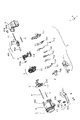
本実施例の像振れ補正をするシフトユニットの詳細を説明する前に、先ず、図1及び図2を用いて、本実施例におけるレンズ鏡筒の全体構成について説明する。図1は本実施例におけるレンズ鏡筒の構成を示す分解斜視図、図2は本実施例におけるレンズ鏡筒の構成を示す主要断面図である。なお、これらの図において説明のために一部の形状は省略されている。
[Example 1]
In Example 1, the present invention is applied to a lens barrel having a variable magnification optical system having a convex / concave / convex / convex / convex four-group configuration by a first lens group, a second lens group, a third lens group, and a fourth lens group. The third lens unit is configured with a shift unit that corrects image blur.
Before describing the details of the shift unit for image blur correction according to the present embodiment, first, the overall configuration of the lens barrel according to the present embodiment will be described with reference to FIGS. 1 and 2. FIG. 1 is an exploded perspective view showing the configuration of the lens barrel in this embodiment, and FIG. 2 is a main cross-sectional view showing the configuration of the lens barrel in this embodiment. In these drawings, some shapes are omitted for explanation.
図1及び図2において、L1は固定の第1レンズ群、L2は光軸方向に移動することにより変倍動作を行う第2レンズ群、L3は光軸と垂直な平面内を移動してぶれ補正動作を行う第3レンズ群である。尚、第3レンズ群L3は、第3aレンズ群L3aと、第3bレンズ群L3bとにより構成されている。L4は光軸方向に移動することにより合焦動作を行う第4レンズ群である。
また、1は第1レンズ群L1を保持する前玉鏡筒、2は第2レンズ群L2を保持する変倍移動枠、3は第3レンズ群L3を光軸と垂直な平面内で移動可能とするシフトユニットである。4は第4レンズ群を保持する合焦移動枠、5はその前端が前玉鏡筒と3本のビスで前方から結合された固定鏡筒である。
6はCCD等の撮像素子601が固定される後部鏡筒である。602は撮像素子601を後部鏡筒6に取り付けるための中間部材である。
1 and 2, L1 is a fixed first lens group, L2 is a second lens group that performs a zooming operation by moving in the optical axis direction, and L3 is moved in a plane perpendicular to the optical axis. It is the 3rd lens group which performs correction | amendment operation | movement. The third lens unit L3 includes a 3a lens unit L3a and a 3b lens unit L3b. L4 is a fourth lens group that performs a focusing operation by moving in the optical axis direction.
Reference numeral 1 denotes a front lens barrel that holds the first lens unit L1, 2 denotes a zooming movement frame that holds the second lens unit L2, and 3 denotes that the third lens unit L3 can be moved in a plane perpendicular to the optical axis. Is a shift unit. Reference numeral 4 denotes a focusing moving frame for holding the fourth lens group, and 5 denotes a fixed barrel whose front end is coupled to the front lens barrel from the front by three screws.
Reference numeral 6 denotes a rear lens barrel to which an
後部鏡筒6は、固定鏡筒5に対して位置決めされ、シフトユニット3を挟み込んだ上で2本のビスと一箇所の係合部(係合爪603と係合穴501)により前方から固定される。中間部材602は、撮像素子601を接着等により固定した後、後部鏡筒6に対してビス止により固定される。
シフトユニット3は固定鏡筒5と後部鏡筒6に位置決めされた上で挟み込まれ、2本のビスにより前方からビス締め固定されている。
7は光量調節ユニットであり、他の光学要素の駆動手段である。光軸付近において押え板701、2枚の絞り羽根702,703、仕切り板704、絞り地板705およびNDフィルター706、ND地板707、絞りアーム708、NDアーム709、ビス710より構成されている。2枚の羽根702、703を光軸に垂直な平面内を互いに逆方向に移動させて光学系の開口径を変化させる、いわゆるギロチン式の光量調節装置とされている。
光量調節ユニット7は、ビス710によりシフトユニット3に固定されている。また、NDフィルター706は2濃度であり、絞り羽根702、703とは独立して進退可能である。
The rear barrel 6 is positioned with respect to the fixed
The shift unit 3 is positioned between the fixed
Reference numeral 7 denotes a light amount adjustment unit, which is a driving means for other optical elements. In the vicinity of the optical axis, it is composed of a
The light amount adjustment unit 7 is fixed to the shift unit 3 with
8は固定鏡筒5と後部鏡筒6とによりその両端が保持されたガイドバーであり、9は固定鏡筒5に圧入保持されたガイドバーである。
また、10、11は後部鏡筒6とシフトユニット3とによりその両端を保持されたガイドバーである。変倍移動枠2はガイドバー8と9、また合焦移動枠4はガイドバー10と11により光軸方向に移動可能に支持されている。なお、変倍移動枠2及び合焦移動枠4はそれぞれ、一方のガイドバーに対して光軸方向に所定の長さを有するスリーブ部で嵌合することにより、光軸方向への倒れが防止され、他方のガイドバーにU溝部で係合することにより上記一方のガイドバー回りでの回転が防止される。
200は、第2レンズ群L2を光軸方向に移動し変倍動作を行わせる為のステッピングモータ(以下ズームモータともいう)であり、回転するロータ201と、同軸のリードスクリュー202とを有する。
また、リードスクリュー202には変倍移動枠2に取り付けられたラック203が噛み合っており、ロータ201及びリードスクリュー202が回転することにより変倍移動枠2(第2レンズ群L2)が光軸方向に駆動される。ステッピングモータ200は2本のビスによって固定鏡筒5と後部鏡筒6にまたがって固定されている。
なお、変倍移動枠2とラック203との間に配置されたねじりコイルばね204によって、変倍移動枠2がガイドバー8、9に対してガイドバー径方向に、ラック203が変倍移動枠2に対して光軸方向に、さらにラック203がリードスクリュー202への噛み合い方向にそれぞれ片寄せ付勢され、各部のガタをなくしている。
Further, the
The
205はフォトインタラプタからなるズームリセットスイッチであり、変倍移動枠2に形成された遮光部206の光軸方向への移動による遮光/透光状態の切り換えを電気的に検出し、第2レンズ群L2の基準位置を検出する。ズームリセットスイッチ205はビスにより固定鏡筒5に固定されている。
400は第4レンズ群L4を光軸方向に移動し合焦動作を行わせる為のフォーカスモータ(ボイスコイルモータ)であり、コイル401、ドライブマグネット402、2つのヨーク403a、403bから構成されている。コイル401に電流を流すと、コイル401とマグネット402の間に発生する磁力線相互の反発によるローレンツ力が発生し、移動群L4を移動せしめる。
また、合焦移動枠4には光軸方向に多極着磁された不図示のセンサマグネットが保持されている。また、固定鏡筒5には該センサマグネットと光軸外側に対向した位置にMRセンサ404が保持されており、MRセンサ404からの信号を用いることで、移動群L4の所定の基準位置を検出することができる。
In addition, the focusing moving frame 4 holds a sensor magnet (not shown) that is multipolarly magnetized in the optical axis direction. The fixed
次に、図3〜図6を用いて第3レンズ群L3を光軸に直交な平面内で移動可能とするシフトユニット3の構成について詳しく説明する。
図3はシフトユニット3をユニット分解し像面方向から見た図、図4はシフトユニット3の分解斜視図、図5はシフトユニット3及び光量調節ユニット7の断面図である。
本実施例のシフトユニット3は、3つのユニット、つまりシフトマグネットユニット31、シフトベースユニット32、シフト移動枠ユニット33より構成されている。このうちシフトベースユニット32はベース部材を、また、シフトマグネットユニット31とシフト移動枠ユニット33はシフトベースユニット32をその間に配置した状態で、ビス301により一体となり可動部材を構成している(以下、シフトマグネットユニット31とシフト移動枠ユニット33を一体として表現するときは可動ユニット34と記述する。)
可動ユニット34は、第3レンズ群L3を保持した状態でカメラの横方向またはカメラの縦方向の振れによる像振れを補正するために、ヨー方向(光軸に垂直な面内における水平方向;第一の方向)またはピッチ方向(光軸に垂直な面内における垂直方向;第二の方向)に、シフトベースユニット32に対してシフト移動可能となっている。
Next, the configuration of the shift unit 3 that enables the third lens unit L3 to move within a plane orthogonal to the optical axis will be described in detail with reference to FIGS.
3 is an exploded view of the shift unit 3 as viewed from the image plane direction, FIG. 4 is an exploded perspective view of the shift unit 3, and FIG. 5 is a cross-sectional view of the shift unit 3 and the light amount adjustment unit 7.
The shift unit 3 of the present embodiment includes three units, that is, a
The
331、332はそれぞれシフト移動枠ユニットを構成している第1シフト鏡筒、第2シフト鏡筒であり、第1シフト鏡筒331は第3aレンズ群L3aを、第2シフト鏡筒332は第3レンズ群L3bを保持している。
第1シフト鏡筒331には、第3aレンズ群L3aを保持するレンズ保持部331aと、第2シフト鏡筒332とを連結する連結部331bとが設けられている。
第1シフト鏡筒331と第2シフト鏡筒332は、相対的な偏心をなくする、すなわち第3aレンズ群L3aと第3bレンズ群L3bの光軸を合わせるための調整を行った後、接着固定される。
第2シフト鏡筒332は第1シフト鏡筒331の連結部331bに対して接着され、第3aレンズ群L3aと第3bレンズ群L3bとの光軸方向間隔は一定である。
311はシフトマグネットユニット31を構成しているマグネットベース、312は同じくシフトマグネットユニット31を構成している金属プレートである。マグネットベース311の光軸像面側の面と金属プレート312の光軸方向前玉側の面は接している。金属プレート312の材質としては、例えばステンレス鋼などが適している。
The
The first
The second
321はシフトベースユニット32を構成しているシフトベースであり、固定鏡筒5と後部鏡筒6との間に挟み込まれて固定される。
322a、322b、322cはシフトベースユニット32を構成している金属プレートである。これらはシフトベースの表面に形成された凹部の空間内に配置される。具体的には、金属プレート322a、322b、322cはシフトベース321に設けられた凹部321a、321b、321cにそれぞれ配置される。金属プレート322a、322b、322cの材質としては、例えばステンレス鋼が適当である。
323a、323b、323cは金属プレート322a、322b、322cと、金属プレート312との間に挟持された3つのボールである。これらボール323a、323b、323cは、その近傍に配置されている、後述するマグネットに吸引されないように、例えばステンレス鋼が適当である。
また、3つのボール323a、323b、323cは金属プレート322a、322b、322cにそれぞれ当接し、さらにマグネットベース311に接して一体となった金属プレート312上の面312a、312b、312cに当接する。これら3箇所ずつの当接面は、光学系の光軸に対して略垂直な面であり、3つのボール323a、323b、323cの呼び径が同じ場合は、3箇所の当接面の光軸方向位置の相互差を小さく抑えることにより、可動部ユニット34を光軸に対して直角な姿勢を保ったままで保持及びシフト案内が可能となる。
302は、円筒形状の棒を略90度に屈曲させたL形軸であり、後述するように回転防止手段を構成している。L形軸302の材質にはSUS303のようなステンレス鋼が好適である。
L形軸302はシフトベース321に設けられた、後述する支持部にピッチ方向に組み込んだ後、シフトマグネットユニット31とシフト移動枠ユニット33を一体化する際、マグネットベース311や第1シフト鏡筒331に設けられた、後述する支持部に組み込まれる。
The three
The L-shaped
次に、シフトユニット3の駆動手段について説明する。
なお、ピッチ方向及びヨー方向の駆動手段及び位置検出手段は、同一構成を有し、光軸回りに90度の位相差を持っているのみであるので、ここではピッチ方向の駆動手段について説明する。図中ピッチ方向の番号にはp、ヨー方向の番号にはyの添え字を記す。
313pは光軸に対して放射方向に2極着磁された位置検出機能も兼用する駆動用マグネットである。314pはマグネット313pの光軸方向前玉側の磁束を閉じるためのバックヨーク、324pはコイル、325pはマグネット313pの光軸方向像面側の磁束を閉じるためのヨークである。ヨーク325pは、マグネット313pとは光軸方向において略同一の投影形状を有している。326はフレキシブルプリントケーブル(以下FPCと記す)である。
マグネット313pはマグネットベース311に圧入することにより位置決め固定されている。バックヨーク314pはマグネットベースに、光軸中心方向にスライドさせて組み込まれる。コイル324pはシフトベース321に圧入により固定されている。ヨーク325pはシフトベース321に光軸中心方向にスライドさせて組み込まれる。
Next, driving means for the shift unit 3 will be described.
The pitch direction and yaw direction drive means and position detection means have the same configuration and only have a phase difference of 90 degrees around the optical axis. Therefore, the pitch direction drive means will be described here. . In the figure, the number in the pitch direction is p, and the number in the yaw direction is y.
The
また、ヨーク325pは半抜き加工により凸部325’pが設けられている。これらの凸部325’pはマグネット313pの2極着磁の両磁極からほぼ均等な距離にあるので、両方の磁極が凸部325’pを引っ張る力もほぼ均等となり、バランスの取れた状態になっている。321d、321e、321f、321g、321h、321i、321j、321kはFPC326を位置決め固定するためにシフトベース321に設けられた部材であり、FPC326は該位置決め部材321d〜321kに組み込むことにより位置決めされシフトベース321に固定される。
コイル324pとヨーク325pはシフトベース321に固定され、マグネット313pとバックヨーク314pはマグネットベース311に固定されている。そして、これらマグネット313pとバックヨーク314pとヨーク325pとにより磁気回路が形成される。コイル324pはこの磁気回路内に配置された構成であるため、コイル324pに電流を流すと、マグネット313pにおける2極着磁の着磁境界に対して略直角方向に、磁石とコイルに発生する磁力線相互の反発によるローレンツ力が発生し、マグネットと共に可動部ユニット34がシフト移動する。
Further, the
The
このような構成の駆動手段がピッチ方向及びヨー方向に関して設けられているので、光軸直交平面内で略直交するピッチ方向及びヨー方向への駆動力を与えることができる。
すなわち、本実施形態は、マグネット313pを含む磁気回路のギャップにコイル324pを配置し、マグネット313pとともに可動ユニット34及び第3レンズ群L3aをシフト駆動する、いわゆるムービングマグネット型の駆動手段となっている。
また、マグネット313pとヨーク325pの間には磁気的吸引作用が生じ、この吸引力によってヨーク325pはマグネット313p側に引き付けられる。つまり、ピッチ方向及びヨー方向の磁気回路での合力が、3つのボール323a〜323cの内側に働くように、これら磁気回路及びボール323a〜323cを配置することで、3つのボール323a〜323cを挟んで可動ユニット34をシフトベース321側に付勢することができる。
Since the driving means having such a configuration is provided with respect to the pitch direction and the yaw direction, it is possible to apply a driving force in the pitch direction and the yaw direction substantially orthogonal to each other in the optical axis orthogonal plane.
That is, the present embodiment is a so-called moving magnet type driving means in which the
Further, a magnetic attraction action occurs between the
また、3つのボール323a〜323cと金属プレート322a〜322c及び金属プレート312の当接面との間には、上記吸引力に依らなくてもボール323a〜323cがシフトベース321及び可動ユニット34の間から用意に脱落しない程度の粘度を有する潤滑油が塗布されており、上記吸引力を上回る慣性力が可動ユニット34に働いて金属プレート312の当接面312a〜312cがボール323a〜323cから浮いた状態となっても、ボール323a〜323cの位置が容易にずれるのを防止できる。
Further, between the three
次に、図6(a)及び図6(b)を用いてボール323aに対するシフトベースユニット32と可動ユニット34との関係を説明する。
なお、他のボール323b、323cについても同一の関係となっているため、ここでは323aについてのみ説明する。
図6(a)はボール323aの略中心を光軸に略平行な面で切った断面図を模式化したものである。図6(b)はボール323a及びその周囲を前玉方向から見た模式図である。
327aは、シフトベース321に設けられた、光軸方向視において矩形状の開口を有する凹部321aに金属プレート322aを配置して形成される空間である。ボール323aは図6(a)に示す空間327a内に配置され、金属プレート322aの内底面322a1と当接する。ボール323aの移動は金属プレート322aの内側面322a2、322a3と、シフトベース321の内壁321a1、321a2で形成される4つの面、つまり、当接面322a1を囲んだ4面により制限されている。
Next, the relationship between the
Since the
FIG. 6A schematically shows a cross-sectional view of the
327a is a space formed by disposing a
ボール323aは金属プレート322aの面322a1及び金属プレート312の当接面312aにそれぞれ当接した状態で、該4面322a2、322a3、321a1、321a2により制限された範囲内を移動する。尚、これらボール323a、金属プレート322a、金属プレート312、ボールの移動を制限する4面322a2、322a3、321a1、321a2、及びボールの移動する領域の全てによって、可動ユニット34をシフトベースユニット32に対し、光軸と垂直な面内方向に移動させる可動部材の支持案内手段が構成される。
また、ボール323aは、金属プレート322aと金属プレート312に挟持され移動制限範囲内を転動する。ここで、転がり摩擦は滑り摩擦に対して十分小さいので、ボール323aは金属プレート322a及び金属プレート312の当接面322a1及び312aに対して滑ることがなく、ボール323aを転がしながら可動ユニット34はシフトベースユニット32に対して移動し、このとき、ボール323aの中心に対して、可動ユニット34とシフトベースユニット32は相対移動するため、シフトベースユニット32に対するボール323aの移動量は可動ユニット34の移動量の半分となる。
The
Further, the
次に、位置検出手段について説明する。
前述したように、313pは位置検出兼駆動用のマグネットである。
328pは磁束密度を電気信号に変換するホール素子であり、FPC326の光軸像面側に半田付けにより固定される。FPC326は圧入固定されているコイル324pの光軸前玉側の面を覆うように固定されるため、ホール素子328pはコイル324pの内側に配置される構成となる。
可動部ユニット34及び第3レンズ群L3がピッチ方向若しくはヨー方向に駆動されたとき、ホール素子328p(シフトベースユニット32側)によってマグネット313p(可動ユニット34側)の磁束密度の変化が検出され、この磁束密度の変化を示す電気信号がホール素子328pから出力される。このホール素子328pからの電気信号に基づいて、後述のコントロール回路(図11の37)が可動ユニット34及び第3レンズ群L3の位置を検出することができる。
Next, position detection means will be described.
As described above, 313p is a magnet for position detection and driving.
When the
また、ピッチ方向、ヨー方向それぞれの2極着磁の境界が自らの検出方向軸(ピッチ方向軸及びヨー方向軸)に対して直角に配置されているため、他方のマグネット313pの検出方向軸の動きに対して、その動きがマグネット313pの大きさに比べて小さい場合は、ホール素子328pに対する磁束分布が実用上変化しない。このため、2軸独立に可動ユニット34の位置を検出することができる。
また、本実施例のように、一つのマグネットで駆動と位置検出の両方を共用させることで、従来の位置検出手段を構成している公知のセンサマグネットが不要となり、シフトユニット3全体の光軸方向の薄型化が可能となっている。
In addition, since the boundary of the two-pole magnetization in each of the pitch direction and the yaw direction is arranged at right angles to its own detection direction axis (pitch direction axis and yaw direction axis), the detection direction axis of the
Further, as in this embodiment, by sharing both driving and position detection with a single magnet, a known sensor magnet constituting conventional position detecting means becomes unnecessary, and the optical axis of the entire shift unit 3 is eliminated. Directional thinning is possible.
次に、再び図1と図5を用いて光量調節ユニット7とシフトユニット3の位置関係について説明する。
333は第1のシフト鏡筒におけるレンズ保持部331a、第2シフト鏡筒332及び両側の連結部331bにより囲まれた空間であり、この空間333の光軸方向寸法は、光量調節ユニット7の押え板701〜ND地板707までの光軸方向寸法よりも若干大きくなっている。光量調節ユニット7は、レンズ前玉方向から見て可動ユニット34のピッチ移動方向下側、つまりレンズ正姿勢におけるシフトユニット3の下側に隣接している。
Next, the positional relationship between the light amount adjustment unit 7 and the shift unit 3 will be described with reference to FIGS. 1 and 5 again.
次に、光量調節ユニット7の組立て方について説明する。
光量調節ユニット7は、該空間333内に、光軸直交方向にシフトユニットのピッチ方向下側から挿入され、シフトベース3に対して、ビス708により固定される。このように、シフトユニット3の空間333内に対して光量調節ユニット7を後から差し込みシフトベース3にビス止め固定するという構成をとることにより、光量調節ユニット7の組み付け前においてシフトユニット3の単品での性能評価を容易に行うことができ、かつ光量調節ユニット7の組み付け作業も容易である。
Next, how to assemble the light amount adjustment unit 7 will be described.
The light quantity adjustment unit 7 is inserted into the
次に、再び図3、図4を用いてL形軸の案内手段について説明する。
321g、321hはシフトベースに設けられた凹型形状の支持部である。331c、331dは第1シフト鏡筒331に設けられた支持部であり、L形軸302のヨー方向の光軸像面方向を支持している。L形軸302が該支持部321g、321hと相対摺動することで、可動ユニット34は光軸直交平面内の回転を抑制されヨー方向へ移動する。これらの支持部321g、321h、331c、331dの全てによって、第一の案内手段が構成される。
321i、321jは、シフトベース321に設けられた支持部であり、支持部321i、321jによりL形軸302のピッチ方向の光軸方向位置が決まる。311a、311bはマグネットベース311に設けられた凹型形状の支持部である。可動ユニット34は支持部311a、311bを以ってL型軸302と相対摺動することにより光軸直交平面内の回転を抑制されながらピッチ方向にシフト移動する。これらの支持部321i、321j、311a、311bの全てによって、第二の案内手段が構成される。
Next, the guide means for the L-shaped shaft will be described with reference to FIGS. 3 and 4 again.
図7を用いて案内手段の寸法構成について説明する。
図7はL形軸302と前記案内手段の構成をわかりやすく説明するためにL形軸302と案内手段を、L形軸302の軸方向に対して略垂直方向に切断した断面模式図である。
DはL形軸302の外径寸法である。H1は、支持部311a、311b及び支持部321g、321hの凹部の光軸方向開口幅寸法であり、その大きさはL形軸302が嵌合する寸法とする。H2は支持部321i、321jの光軸方向対向面間隔寸法であり、同様にL形軸302が嵌合する寸法である。支持部321iや321jはシフトベースユニット32を構成するシフトベース321に設けられているため、支持部321i、321jの光軸方向寸法を嵌合寸法にすることでL形軸302の光軸方向の位置が決まる。
The dimensional configuration of the guide means will be described with reference to FIG.
FIG. 7 is a schematic cross-sectional view of the L-shaped
D is the outer diameter of the L-shaped
一方このとき、支持部311a、311b及び支持部331c、331dがL形軸302の光軸方向を支持している面とL形軸302までの間隔は若干遊びを持った寸法となっている。支持部311a、311b及び支持部331c、331dはそれぞれ可動ユニット34側に設けられており、可動ユニット34はシフトベースユニット32を介して光軸方向の位置が決まっているため、仮に光軸方向の寸法公差が積み重なった場合にもそれを逃げられる最小限の余裕が必要となるからであり、このような寸法構成をとることで、L形軸302を光軸方向及び光軸直交の双方に詰まることなく、摺動案内することができる。
On the other hand, the space between the L-shaped
次に図8を用いて、光軸方向から見たときのL形軸302と前記案内手段との位置関係について説明する。
図8はシフトユニット3と光量調節ユニット7を前玉方向から見た図である。尚、図8はシフトユニット3の内部の構成、位置関係をわかりやすく説明するためにL形軸302、前記案内手段及び前記可動部の支持案内手段を点線で表示し、光軸直交平面内における可動部材の支持案内手段が占める領域を斜線A、Bで示し、一部形状は省略している。
図8に示されるように、光軸方向から見て支持部321g、321h、331c、331dが配列されているピッチ方向間に、可動部材の支持案内手段Aが配置されている。また、支持部321i、321j、311a、311bが配列されているヨー方向間に、可動部材の支持案内手段Bが配置されている。これらにより、嵌合長を極力長くする構成が採られている。
このように嵌合長を長くする構成により、L形軸302の嵌合ガタ内におけるふれ角を極力小さくし、可動ユニット34のピッチ方向、ヨー方向の案内をより正確に行うことができる。
Next, the positional relationship between the L-shaped
FIG. 8 is a view of the shift unit 3 and the light amount adjustment unit 7 as seen from the front lens direction. In FIG. 8, the L-shaped
As shown in FIG. 8, the support guide means A for the movable member is disposed between the pitch directions in which the
In this way, the configuration in which the fitting length is increased makes it possible to minimize the deflection angle of the L-shaped
また、シフトユニット3を径大化させることなく嵌合長を長く構成にするために、本実施例では可動部材の支持案内手段の光軸方向にL形軸302が移動するに十分なだけのスペースを確保している。このため、図8に示すように光軸方向から見て、可動部材の支持案内手段A、BとL形軸302とは、ピッチ方向、ヨー方向共にその一部が重なる構成となっており、シフトユニット3を径大化することなく嵌合長を長くとることが可能となっている。さらに、本実施例では、光量調節ユニット7が可動ユニット34のピッチ移動下方向に隣接していることから、L形軸302の移動方向をヨー方向とすることで、つぎに説明するようにレンズ鏡筒の小径化を図る上で有効である。
Further, in order to make the fitting length long without increasing the diameter of the shift unit 3, in this embodiment, the L-shaped
次に、L形軸302の移動方向の詳細について、図9(a)、図9(b)を用いて説明する。
図9(a)、図9(b)はL形軸302の移動と、可動ユニット34、シフトベースユニット32の関係をわかりやすく説明するために、L形軸302及び支持部311a、311b、321g、321hのみを示した模式図である。なお、図9(a)は可動ユニット34がピッチ方向に移動する場合、図(b)はL形軸302及び可動ユニット34がヨー方向に移動する場合の模式図である。
図9(a)、図9(b)に示しているもののうち、移動しない部材を斜線で示している。
可動ユニット34がピッチ方向に移動するとき、L形軸302はその移動を摺動案内するのみであるが、可動ユニット34がヨー方向に移動するときは、可動ユニットと一体となり、支持部321g、321hと相対摺動しながらヨー方向へ移動する。
Next, details of the moving direction of the L-shaped
9 (a) and 9 (b) illustrate the movement of the L-shaped
Of those shown in FIGS. 9A and 9B, the non-moving members are indicated by hatching.
When the
本実施例では、シフトユニット3に隣接している光量調節ユニット7は可動ユニット34のピッチ移動下方向に隣接しているため、L形軸302の移動方向を光量調節ユニット7のないヨー方向に移動する構成としてる。仮にL形軸302の移動方向をピッチ方向とした構成としたならば、隣接する光量調節ユニット7をL形軸302の移動量分だけ光軸外周側へずらさなければならず、レンズ鏡筒の径大化を招いてしまうからである。よって、本実施例のような構成とすることで、シフトユニット3を径大化することなく、レンズ鏡筒の小径化に有効となる。また、本実施例では可動ユニット34がピッチ方向に移動するときに、L形軸302の自重の影響を受けることなく移動できるので、可動ユニット34を駆動する前記駆動手段の駆動力を余計に使うことがなく、省エネルギーに寄与できる。
In the present embodiment, the light amount adjustment unit 7 adjacent to the shift unit 3 is adjacent to the downward movement of the
以上のように、本実施例によれば、光軸方向から見て、可動部材の支持案内手段A、Bと、L形軸302とが、ピッチ方向、ヨー方向とにおいて一部が重なるように構成することで、シフトユニット3を径大化することなく、小型化を図ることが可能となる。
なお、上記実施例では、ムービングマグネット型のアクチュエータを用いて第3レンズ群L3を駆動する場合について説明したが、本発明は、コイルを可動部材に設け、マグネットをベース部材に設けたムービングコイル型のアクチュエータを用いる場合にも適用することができる。
また、上記実施例では、可動ユニットが2体に分かれた構成について説明したが、本発明はこのような2体に分かれたユニットに限定されるものではない。
また、上記実施例では、可動部材の光軸回りの回転防止手段をL形軸302によるもので説明したが、他に例えば案内溝を有する図10のような板や、ピッチ方向、ヨー方向にそれぞれ独立した、例えば特許文献1のような、ピッチシヤフト、ヨーシヤフト等による回転防止手段でもよく、可動部材の回転を規制できるものであればよく、本実施例の構成に限定されるものではない。
また、可動部材の支持案内手段はボールによるもので説明したが、可動部材もしくは固定部材に放射方向に固定されたピンと、光軸方向を規制する長溝による案内手段でもよい。
As described above, according to the present embodiment, when viewed from the optical axis direction, the support guide means A and B of the movable member and the L-shaped
In the above embodiment, the case where the third lens unit L3 is driven using a moving magnet type actuator has been described. However, the present invention is a moving coil type in which a coil is provided on a movable member and a magnet is provided on a base member. This can also be applied to the case of using the actuator.
Moreover, although the said Example demonstrated the structure which divided the movable unit into two bodies, this invention is not limited to such a unit divided into two bodies.
Further, in the above embodiment, the rotation preventing means around the optical axis of the movable member has been described by the L-shaped
The support guide means for the movable member is described as a ball, but it may be a guide means by a pin fixed in a radial direction to the movable member or the fixed member and a long groove for regulating the optical axis direction.
[実施例2]
実施例2においては、実施例1の像ぶれ補正を可能としたレンズ鏡筒を搭載したカメラを構成した。
[Example 2]
In the second embodiment, a camera equipped with a lens barrel that enables image blur correction of the first embodiment is configured.
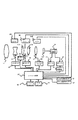
図11に、実施例1のレンズ鏡筒を搭載したカメラの電気回路構成を説明するブロック図を示す。
図11において、1133は第2レンズ群2の駆動源であるズームモータである。1134は第4レンズ群4の駆動源であるボイスコイルモータのコイルである。
35は光量調節ユニット7の駆動源である絞りモータであり、ステッピングモータ等が用いられる。
フォトインタラプタ205は、第2レンズ群L2が光軸方向における基準位置に位置しているか否かを検出するズームリセットスイッチである。第2レンズ群L2が基準位置に位置したことが検出された後、ズームモータ1133に入力するパルス信号数を連続してカウントすることにより、第2レンズ群L2の光軸方向の移動量(基準位置に対する位置)の検出を行うことができる。36は絞りエンコーダである。
37はカメラの制御を司る、CPU等からなるコントロール回路である。38はカメラ信号処理回路であり、撮像素子601からの出力に対して所定の増幅やガンマ補正などの信号処理を施す。これらの処理を受けた映像信号のコントラスト信号は、AEゲート39よびAFゲート40に供給される。AEゲート39及びAFゲート40はそれぞれ、露出制御およびピント合わせのために最適な信号の取り出し範囲を全画面の映像信号の中から設定する。ゲートの大きさは可変であったり、複数設けられたりする場合がある。
FIG. 11 is a block diagram illustrating an electric circuit configuration of a camera equipped with the lens barrel of the first embodiment.
In FIG. 11, reference numeral 1133 denotes a zoom motor that is a drive source of the second lens group 2. Reference numeral 1134 denotes a coil of a voice coil motor that is a drive source of the fourth lens group 4.
The
41はAF(オートフォーカス)のためのAF信号を処理するAF信号処理回路であり、映像信号の高周波成分に関する1つもしくは複数の出力を生成する。42はズームスイッチ、43はズームトラッキングメモリである。ズームトラッキングメモリ43は、変倍に際して被写体距離とバリエータ(第2レンズ群L2)の位置に応じたフォーカシングレンズ(第4レンズ群L4)の位置情報を記憶している。なお、ズームトラッキングメモリとして、コントロール回路37内のメモリを使用してもよい。
例えば、撮影者によりズームスイッチ42が操作されると、コントロール回路37は、ズームトラッキングメモリ43の情報をもとに算出した第2レンズ群L2と第4レンズ群L4の所定の位置関係が保たれるように、現在の第2レンズ群L2の光軸方向の絶対位置を示すカウント値と算出された第2レンズ群L2のセットすべき位置とが一致し、かつ現在の第4レンズ群L4の光軸方向の絶対位置を示すカウント値と算出された第4レンズ群L4のセットすべき位置とが一致するように、ズームモータ1133とフォーカスモータ1134の駆動を制御する。 また、オートフォーカス動作では、コントロール回路37は、AF信号処理回路41の出力がピークを示すようにボイスコイルモータの駆動を制御する。
さらに、適正露出を得るために、コントロール回路37は、AEゲート39を通過したY信号の出力の平均値を基準値として、絞りエンコーダ35の出力がこの基準値となるように絞りモータ35の駆動を制御し、光量をコントロールする。51、52はピッチ方向およびヨー方向の角度変化を検出するための振動ジャイロ等の振れセンサであり、コントロール回路37は、これら振れセンサ51、52からの出力と、ホールセンサ328からの信号とに基づいてコイル324への通電を制御して第3レンズ群L3を駆動し、像振れを補正する。
Reference numeral 41 denotes an AF signal processing circuit that processes an AF signal for AF (autofocus), and generates one or a plurality of outputs related to high-frequency components of the video signal.
For example, when the photographer operates the
Further, in order to obtain an appropriate exposure, the
上記実施例では、レンズ鏡筒がカメラ本体に一体的に設けられた撮像装置について説明したが、本発明のレンズ鏡筒は、カメラ本体に対して着脱可能な交換レンズ装置や、あるいは35mmフィルム用の写真カメラやデジタルスチルカメラやビデオカメラ等にも適用できる。また、防振機能を有する双眼鏡等の観察機器等の光学機器にも適用することができる。 In the above-described embodiments, the imaging apparatus in which the lens barrel is integrally provided on the camera body has been described. However, the lens barrel of the present invention is for an interchangeable lens apparatus that can be attached to and detached from the camera body, or for a 35 mm film. It can also be applied to other photo cameras, digital still cameras, video cameras, and the like. Further, the present invention can also be applied to an optical apparatus such as an observation apparatus such as binoculars having a vibration isolation function.
L1:第1レンズ群
L2:第2レンズ群
L3:第3レンズ群
L3a:第3aレンズ群
L3b:第3bレンズ群
L4:第4レンズ群
1:前玉鏡筒
2:変倍移動枠
3:シフトユニット
4:合焦移動枠
5:固定鏡筒
6:後部鏡筒
7:光量調節ユニット
31:シフトマグネットユニット
32:シフトベースユニット
33:シフト移動枠ユニット
34:可動ユニット
302:L形軸
329:金属プレート
601:撮像素子
711:フレキシブルプリント
L1: First lens group L2: Second lens group L3: Third lens group L3a: Third lens group L3b: Third lens group L4: Fourth lens group 1: Front lens barrel 2: Variable magnification moving frame 3: Shift unit 4: Focus moving frame 5: Fixed lens barrel 6: Rear lens barrel 7: Light amount adjusting unit 31: Shift magnet unit 32: Shift base unit 33: Shift moving frame unit 34: Movable unit 302: L-shaped shaft 329: Metal plate 601: Image sensor 711: Flexible print
Claims (3)
前記可動部材の前記ベース部材に対する光軸方向への移動を3箇所の規制部で規制し、前記可動部材の前記光軸と垂直な面内方向への移動を案内する可動部材の支持案内手段と、前記可動部材の光軸まわりの回転を規制する回転防止手段と、
前記回転防止手段を、前記ベース部材に対して前記光軸と垂直な面内方向において第一の方向への移動を案内する第一の案内手段と、前記可動部材を前記回転防止手段に対して前記光軸と垂直な面内方向において前記第一の方向と直交する第二の方向への移動を案内する第二の案内手段と、を有し、
前記3箇所の規制部の各々は、前記可動部材と前記ベース部材との対向面間において、前記ベース部材の表面に形成された凹部の空間内に保持されたボールを備えており、
前記第一の案内手段は、前記ベース部材に設けられた2箇所の支持部を備え、前記可動部材の支持案内手段における前記3箇所の規制部のうちの1箇所の規制部が光軸方向から見て前記2箇所の支持部の間に配置されており、
前記第二の案内手段は、前記可動部材に設けられた2箇所の支持部を備え、前記可動部材の支持案内手段における前記3箇所の規制部のうちの前記1箇所の規制部とは別の他の1箇所の規制部が光軸方向から見て前記2箇所の支持部の間に配置されており、
前記ベース部材に設けられた前記第一の案内手段を構成する2箇所の支持部は、前記ベース部材から光軸方向に延設されると共に、
前記可動部材に設けられた前記第二の案内手段を構成する2箇所の支持部は、前記可動部材から光軸方向に延設され、
前記回転防止手段は、略90度に屈曲させたL形部材で構成され、
前記L形部材におけるL形の1辺が、前記3箇所の規制部のうちの1箇所の規制部における前記ベース部材の表面に形成された凹部の空間内に保持されたボールの、前記可動部材と当接している該ボールの背後位置において、
光軸方向から見て前記1箇所の規制部と重なるように、前記第一の案内手段を構成する2箇所の支持部によって支持され、
前記L形部材におけるL形の他辺が、前記3箇所の規制部のうちの前記1箇所の規制部とは別の他の1箇所の規制部における前記ベース部材の表面に形成された凹部の空間内に保持されたボールの、前記可動部材と当接している該ボールの背後位置において、
光軸方向から見て前記別の他の1箇所の規制部と重なるように、前記第二の案内手段を構成する2箇所の支持部によって支持され、ていることを特徴とする像ぶれ補正装置。 In an image blur correction apparatus that includes a movable member that holds a correction lens and a base member, moves the movable member in an in-plane direction perpendicular to the optical axis, and corrects image blur.
A movable member supporting and guiding means for restricting movement of the movable member relative to the base member in the optical axis direction by three restriction portions and guiding movement of the movable member in an in-plane direction perpendicular to the optical axis; Rotation preventing means for restricting rotation of the movable member around the optical axis;
The rotation preventing means includes a first guiding means for guiding movement in a first direction relative to the base member in an in-plane direction perpendicular to the optical axis, and the movable member to the rotation preventing means. Second guiding means for guiding movement in a second direction orthogonal to the first direction in an in-plane direction perpendicular to the optical axis;
Each of the three restricting portions includes a ball held in a concave space formed on the surface of the base member between the opposed surfaces of the movable member and the base member.
The first guide means includes two support portions provided on the base member, and one of the three restriction portions in the support guide means of the movable member is from the optical axis direction. It is arranged between the two support portions as seen,
The second guide means includes two support portions provided on the movable member, and is different from the one restriction portion among the three restriction portions in the support guide means of the movable member. One other restricting portion is disposed between the two supporting portions when viewed from the optical axis direction,
The two support portions constituting the first guide means provided on the base member extend from the base member in the optical axis direction, and
Two support portions constituting the second guide means provided on the movable member are extended from the movable member in the optical axis direction,
The rotation preventing means is composed of an L-shaped member bent at approximately 90 degrees,
Wherein one side of the L-shaped in L-shaped member, a ball held by the base member is formed on the surface of the recess in the space on the regulated portion of the one portion in regulating portion before Symbol three, the movable In a position behind the ball that is in contact with the member,
Supported by the two supporting portions constituting the first guiding means so as to overlap the one restricting portion as seen from the optical axis direction ,
The other side of the L-shaped in the L-shaped member, said recess formed on the surface of the base member in the regulating portion of another alternative one position and one position of the regulating portion of the regulating portion before Symbol three Of the ball held in the space of the back of the ball in contact with the movable member,
As viewed from the optical axis direction overlaps with the restricting portion of the further other one point, the second is supported by the supporting portion of the two portions constituting the guide means, it has the image stabilizer, characterized in .
Priority Applications (3)
| Application Number | Priority Date | Filing Date | Title |
|---|---|---|---|
| JP2005178819A JP4764075B2 (en) | 2005-06-20 | 2005-06-20 | Image blur correction device and lens barrel provided with the image blur correction device |
| US11/444,732 US7747149B2 (en) | 2005-06-20 | 2006-05-31 | Optical apparatus having image-blur correction/reduction system |
| CNB2006100946432A CN100392471C (en) | 2005-06-20 | 2006-06-20 | Optical apparatus having image-blur correction/reduction system |
Applications Claiming Priority (1)
| Application Number | Priority Date | Filing Date | Title |
|---|---|---|---|
| JP2005178819A JP4764075B2 (en) | 2005-06-20 | 2005-06-20 | Image blur correction device and lens barrel provided with the image blur correction device |
Publications (3)
| Publication Number | Publication Date |
|---|---|
| JP2006350157A JP2006350157A (en) | 2006-12-28 |
| JP2006350157A5 JP2006350157A5 (en) | 2008-07-31 |
| JP4764075B2 true JP4764075B2 (en) | 2011-08-31 |
Family
ID=37573433
Family Applications (1)
| Application Number | Title | Priority Date | Filing Date |
|---|---|---|---|
| JP2005178819A Active JP4764075B2 (en) | 2005-06-20 | 2005-06-20 | Image blur correction device and lens barrel provided with the image blur correction device |
Country Status (3)
| Country | Link |
|---|---|
| US (1) | US7747149B2 (en) |
| JP (1) | JP4764075B2 (en) |
| CN (1) | CN100392471C (en) |
Families Citing this family (21)
| Publication number | Priority date | Publication date | Assignee | Title |
|---|---|---|---|---|
| JP2008046415A (en) * | 2006-08-17 | 2008-02-28 | Fujinon Corp | Lens device |
| JP4189771B2 (en) * | 2007-01-12 | 2008-12-03 | ソニー株式会社 | Light amount adjusting device and imaging device |
| JP4888129B2 (en) * | 2007-01-23 | 2012-02-29 | 株式会社ニコン | Lens barrel and digital camera |
| JP4483869B2 (en) * | 2007-02-01 | 2010-06-16 | ソニー株式会社 | Image blur correction device, lens barrel, and imaging device |
| JP5142558B2 (en) * | 2007-03-06 | 2013-02-13 | キヤノン株式会社 | Optical apparatus, imaging apparatus including the same, and control method of optical apparatus |
| JP4992478B2 (en) * | 2007-03-07 | 2012-08-08 | 株式会社ニコン | Camera shake correction unit, lens barrel, camera |
| JP5277510B2 (en) * | 2007-08-09 | 2013-08-28 | コニカミノルタ株式会社 | Imaging unit and electronic device |
| JP4488043B2 (en) | 2007-08-28 | 2010-06-23 | ソニー株式会社 | Image blur correction device, lens barrel, and imaging device |
| JP5104423B2 (en) * | 2008-03-11 | 2012-12-19 | ソニー株式会社 | Camera device and lens barrel device |
| JP2009222899A (en) * | 2008-03-14 | 2009-10-01 | Canon Inc | Image blur correction apparatus |
| JP4781439B2 (en) * | 2009-01-19 | 2011-09-28 | キヤノン株式会社 | Blur correction device, imaging device |
| JP5090410B2 (en) | 2009-03-04 | 2012-12-05 | 株式会社リコー | Image blur correction device, lens barrel, imaging device, and portable information terminal |
| JP4804564B2 (en) * | 2009-07-14 | 2011-11-02 | キヤノン株式会社 | Optical apparatus having shake correction device |
| TWI480579B (en) * | 2009-07-24 | 2015-04-11 | Hon Hai Prec Ind Co Ltd | Camera module |
| JP5173961B2 (en) * | 2009-08-05 | 2013-04-03 | キヤノン株式会社 | Optical equipment |
| JP2012078450A (en) * | 2010-09-30 | 2012-04-19 | Canon Inc | Shake correction device, lens barrel, and optical instrument |
| TW201232027A (en) * | 2011-01-17 | 2012-08-01 | Asia Optical Co Inc | Image pickup mechanism |
| TWI477878B (en) * | 2012-06-13 | 2015-03-21 | Ability Entpr Co Ltd | Compensation mechanism and lens module using the same |
| TWI459128B (en) * | 2012-06-20 | 2014-11-01 | Hon Hai Prec Ind Co Ltd | Drive structure of the optical image stabilization |
| WO2014137102A1 (en) * | 2013-03-07 | 2014-09-12 | 자화전자(주) | Camera lens module for mobile terminal |
| JP6685040B2 (en) * | 2015-11-24 | 2020-04-22 | カムイ・イノベーション株式会社 | Ghost reduction device, image pickup apparatus including the same, ghost reduction method, and image pickup optical system |
Family Cites Families (14)
| Publication number | Priority date | Publication date | Assignee | Title |
|---|---|---|---|---|
| US5774266A (en) * | 1992-04-06 | 1998-06-30 | Canon Kabushiki Kaisha | Image stabilizing device |
| JP3229899B2 (en) | 1992-04-20 | 2001-11-19 | キヤノン株式会社 | Image stabilizer |
| JPH05333399A (en) * | 1992-06-03 | 1993-12-17 | Canon Inc | Image blur corrector |
| JPH09211518A (en) * | 1996-02-02 | 1997-08-15 | Canon Inc | Camera and vibration-proof device |
| JP3791057B2 (en) * | 1996-07-29 | 2006-06-28 | 株式会社ニコン | Blur correction device, photographing optical system, and camera |
| JPH10213833A (en) * | 1997-01-28 | 1998-08-11 | Canon Inc | Optical equipment provided with image shaking correcting function and interchangeable lens |
| US5905917A (en) * | 1997-03-14 | 1999-05-18 | Nikon Corporation | Vibration reduction device |
| JPH117051A (en) * | 1997-06-16 | 1999-01-12 | Canon Inc | Lens shifting device |
| US6064827A (en) * | 1997-05-16 | 2000-05-16 | Canon Kabushiki Kaisha | Image stabilizer |
| DE10017357A1 (en) * | 1999-04-09 | 2000-11-16 | Asahi Optical Co Ltd | Arrangement for correcting focused image jitter, drives correction system based on jitter position, and determines whether current jitter position is within correctable region |
| US6415105B1 (en) * | 1999-05-21 | 2002-07-02 | Asahi Kogaku Kogyo Kabushiki Kaisha | Image stabilizer |
| JP2001228498A (en) * | 2000-02-17 | 2001-08-24 | Asahi Optical Co Ltd | Image blur correction device |
| JP4006178B2 (en) * | 2000-12-25 | 2007-11-14 | キヤノン株式会社 | Lens barrel, photographing device and observation device |
| JP2005091731A (en) * | 2003-09-17 | 2005-04-07 | Nikon Corp | Lens barrel |
-
2005
- 2005-06-20 JP JP2005178819A patent/JP4764075B2/en active Active
-
2006
- 2006-05-31 US US11/444,732 patent/US7747149B2/en active Active
- 2006-06-20 CN CNB2006100946432A patent/CN100392471C/en active Active
Also Published As
| Publication number | Publication date |
|---|---|
| JP2006350157A (en) | 2006-12-28 |
| CN1892295A (en) | 2007-01-10 |
| US7747149B2 (en) | 2010-06-29 |
| US20060285839A1 (en) | 2006-12-21 |
| CN100392471C (en) | 2008-06-04 |
Similar Documents
| Publication | Publication Date | Title |
|---|---|---|
| JP4764075B2 (en) | Image blur correction device and lens barrel provided with the image blur correction device | |
| JP6960983B2 (en) | Imaging device with image stabilization function | |
| US7154682B2 (en) | Optical apparatus | |
| US7689109B2 (en) | Optical image stabilizer and optical apparatus | |
| US7460775B2 (en) | Optical apparatus including efficiently arranged shake correction means | |
| US8582205B2 (en) | Lens barrel and optical apparatus including the same | |
| JP5693163B2 (en) | Vibration correction device, lens barrel, and optical apparatus | |
| EP2141539A1 (en) | Blurring correction device and optical apparatus | |
| JP4661915B2 (en) | Image blur correction device, lens barrel device, and camera device | |
| JP2009222899A (en) | Image blur correction apparatus | |
| US8634138B2 (en) | Lens barrel and optical apparatus including the same | |
| JP5436014B2 (en) | Image blur correction device | |
| JP2003057707A (en) | Image blurring correction device | |
| JP5483988B2 (en) | Image blur correction device | |
| JP5294936B2 (en) | Lens barrel and optical apparatus having the same | |
| JP4950425B2 (en) | Optical device | |
| JP2007193374A (en) | Lens barrel, photographing apparatus and observation apparatus | |
| JP2010276842A (en) | Image blurring correcting device | |
| JP2010271513A (en) | Optical vibration-proof device and optical apparatus | |
| JP2015203751A (en) | Lens barrel and imaging apparatus | |
| JP2007034125A (en) | Optical equipment | |
| JP5172024B2 (en) | Optical device | |
| JP2011150086A (en) | Swing correcting device, and optical apparatus using the same | |
| JP2017161665A (en) | Optical instrument having image shake correction device | |
| JP2018189858A (en) | Shake correction device and lens barrel having the same |
Legal Events
| Date | Code | Title | Description |
|---|---|---|---|
| A521 | Written amendment |
Free format text: JAPANESE INTERMEDIATE CODE: A523 Effective date: 20080611 |
|
| A621 | Written request for application examination |
Free format text: JAPANESE INTERMEDIATE CODE: A621 Effective date: 20080611 |
|
| A977 | Report on retrieval |
Free format text: JAPANESE INTERMEDIATE CODE: A971007 Effective date: 20110112 |
|
| A131 | Notification of reasons for refusal |
Free format text: JAPANESE INTERMEDIATE CODE: A131 Effective date: 20110118 |
|
| A521 | Written amendment |
Free format text: JAPANESE INTERMEDIATE CODE: A523 Effective date: 20110308 |
|
| A131 | Notification of reasons for refusal |
Free format text: JAPANESE INTERMEDIATE CODE: A131 Effective date: 20110420 |
|
| A521 | Written amendment |
Free format text: JAPANESE INTERMEDIATE CODE: A523 Effective date: 20110523 |
|
| TRDD | Decision of grant or rejection written | ||
| A01 | Written decision to grant a patent or to grant a registration (utility model) |
Free format text: JAPANESE INTERMEDIATE CODE: A01 Effective date: 20110607 |
|
| A01 | Written decision to grant a patent or to grant a registration (utility model) |
Free format text: JAPANESE INTERMEDIATE CODE: A01 |
|
| A61 | First payment of annual fees (during grant procedure) |
Free format text: JAPANESE INTERMEDIATE CODE: A61 Effective date: 20110610 |
|
| FPAY | Renewal fee payment (event date is renewal date of database) |
Free format text: PAYMENT UNTIL: 20140617 Year of fee payment: 3 |
|
| R150 | Certificate of patent or registration of utility model |
Ref document number: 4764075 Country of ref document: JP Free format text: JAPANESE INTERMEDIATE CODE: R150 Free format text: JAPANESE INTERMEDIATE CODE: R150 |
|
| RD03 | Notification of appointment of power of attorney |
Free format text: JAPANESE INTERMEDIATE CODE: R3D03 |