WO2019244787A1 - Véhicule de transport d'articles - Google Patents
Véhicule de transport d'articles Download PDFInfo
- Publication number
- WO2019244787A1 WO2019244787A1 PCT/JP2019/023634 JP2019023634W WO2019244787A1 WO 2019244787 A1 WO2019244787 A1 WO 2019244787A1 JP 2019023634 W JP2019023634 W JP 2019023634W WO 2019244787 A1 WO2019244787 A1 WO 2019244787A1
- Authority
- WO
- WIPO (PCT)
- Prior art keywords
- unit
- irradiation
- control
- storage
- traveling
- Prior art date
Links
Images


Classifications
-
- B—PERFORMING OPERATIONS; TRANSPORTING
- B65—CONVEYING; PACKING; STORING; HANDLING THIN OR FILAMENTARY MATERIAL
- B65G—TRANSPORT OR STORAGE DEVICES, e.g. CONVEYORS FOR LOADING OR TIPPING, SHOP CONVEYOR SYSTEMS OR PNEUMATIC TUBE CONVEYORS
- B65G1/00—Storing articles, individually or in orderly arrangement, in warehouses or magazines
- B65G1/02—Storage devices
- B65G1/04—Storage devices mechanical
- B65G1/137—Storage devices mechanical with arrangements or automatic control means for selecting which articles are to be removed
- B65G1/1373—Storage devices mechanical with arrangements or automatic control means for selecting which articles are to be removed for fulfilling orders in warehouses
- B65G1/1375—Storage devices mechanical with arrangements or automatic control means for selecting which articles are to be removed for fulfilling orders in warehouses the orders being assembled on a commissioning stacker-crane or truck
-
- B—PERFORMING OPERATIONS; TRANSPORTING
- B65—CONVEYING; PACKING; STORING; HANDLING THIN OR FILAMENTARY MATERIAL
- B65G—TRANSPORT OR STORAGE DEVICES, e.g. CONVEYORS FOR LOADING OR TIPPING, SHOP CONVEYOR SYSTEMS OR PNEUMATIC TUBE CONVEYORS
- B65G1/00—Storing articles, individually or in orderly arrangement, in warehouses or magazines
- B65G1/02—Storage devices
- B65G1/04—Storage devices mechanical
- B65G1/137—Storage devices mechanical with arrangements or automatic control means for selecting which articles are to be removed
- B65G1/1373—Storage devices mechanical with arrangements or automatic control means for selecting which articles are to be removed for fulfilling orders in warehouses
-
- B—PERFORMING OPERATIONS; TRANSPORTING
- B65—CONVEYING; PACKING; STORING; HANDLING THIN OR FILAMENTARY MATERIAL
- B65G—TRANSPORT OR STORAGE DEVICES, e.g. CONVEYORS FOR LOADING OR TIPPING, SHOP CONVEYOR SYSTEMS OR PNEUMATIC TUBE CONVEYORS
- B65G1/00—Storing articles, individually or in orderly arrangement, in warehouses or magazines
- B65G1/02—Storage devices
- B65G1/04—Storage devices mechanical
- B65G1/0492—Storage devices mechanical with cars adapted to travel in storage aisles
-
- B—PERFORMING OPERATIONS; TRANSPORTING
- B65—CONVEYING; PACKING; STORING; HANDLING THIN OR FILAMENTARY MATERIAL
- B65G—TRANSPORT OR STORAGE DEVICES, e.g. CONVEYORS FOR LOADING OR TIPPING, SHOP CONVEYOR SYSTEMS OR PNEUMATIC TUBE CONVEYORS
- B65G1/00—Storing articles, individually or in orderly arrangement, in warehouses or magazines
- B65G1/02—Storage devices
- B65G1/04—Storage devices mechanical
- B65G1/137—Storage devices mechanical with arrangements or automatic control means for selecting which articles are to be removed
- B65G1/1371—Storage devices mechanical with arrangements or automatic control means for selecting which articles are to be removed with data records
-
- G—PHYSICS
- G06—COMPUTING; CALCULATING OR COUNTING
- G06K—GRAPHICAL DATA READING; PRESENTATION OF DATA; RECORD CARRIERS; HANDLING RECORD CARRIERS
- G06K19/00—Record carriers for use with machines and with at least a part designed to carry digital markings
- G06K19/06—Record carriers for use with machines and with at least a part designed to carry digital markings characterised by the kind of the digital marking, e.g. shape, nature, code
- G06K19/06009—Record carriers for use with machines and with at least a part designed to carry digital markings characterised by the kind of the digital marking, e.g. shape, nature, code with optically detectable marking
-
- G—PHYSICS
- G06—COMPUTING; CALCULATING OR COUNTING
- G06K—GRAPHICAL DATA READING; PRESENTATION OF DATA; RECORD CARRIERS; HANDLING RECORD CARRIERS
- G06K7/00—Methods or arrangements for sensing record carriers, e.g. for reading patterns
- G06K7/10—Methods or arrangements for sensing record carriers, e.g. for reading patterns by electromagnetic radiation, e.g. optical sensing; by corpuscular radiation
- G06K7/14—Methods or arrangements for sensing record carriers, e.g. for reading patterns by electromagnetic radiation, e.g. optical sensing; by corpuscular radiation using light without selection of wavelength, e.g. sensing reflected white light
Definitions
- the present invention relates to an article transport vehicle provided with a support for supporting an article.
- Patent Document 1 Japanese Patent Application Laid-Open No. 2008-247546
- the article transport vehicle (picking work cart) of Patent Document 1 is provided in a picking facility.
- the article transport vehicle is moved by a push-pull operation of an operator to move the article transport vehicle near the storage section (article storage section 5) of the target storage shelf (3), and articles are moved from the storage section of the storage shelf.
- a picking operation is performed in which the picked-up article is taken out and supported by the support section (container 8) of the article transport vehicle.
- the article carrier In order to reduce the amount of work of the worker, the article carrier is configured to automatically travel to a set position near the storage section of the target storage shelf, and the worker stops the article stopped at the set position. It is conceivable to perform a picking operation on the transport vehicle. However, when the article transport vehicle is configured to run automatically in this way, when the article transport vehicle is stopped at a position that is invisible or difficult to be seen by the worker, the worker moves the article transport vehicle relative to the article transport vehicle. It may be difficult to notice that it is necessary to perform the picking operation, and the picking operation may not be performed smoothly.
- the article transport vehicle is a traveling unit that travels to a set position set corresponding to each of a plurality of storage units that store articles, a support unit that supports the articles, and an irradiation unit that emits light.
- a control unit that controls the traveling unit and the irradiation unit, wherein the storage unit in which an article to be supported by the support unit is stored is a target storage unit, and the control unit corresponds to the target storage unit.
- Traveling control for controlling the traveling section so that the traveling section travels to the set position set as above, and in a state where the traveling section is at the set position, at a position above a plurality of the storage sections, and And irradiating control for controlling the irradiating unit so as to irradiate light to an irradiating position corresponding to the own vehicle.
- the control unit executes the traveling control, so that the traveling unit travels to the set position, and the control unit executes the irradiation control, so that the irradiation unit emits light to the irradiation position.
- This irradiation position is a position above the plurality of storage units and a position corresponding to the own vehicle, so that even an operator who is away from the article transport vehicle or a worker who is in a place separated by the storage unit, etc. It is possible to recognize that the article transport vehicle that needs to perform the picking operation is at the set position. For this reason, the worker can easily recognize that it is necessary to perform the picking operation on the article transport vehicle, and can easily perform the picking operation.
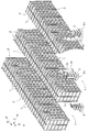
- the picking equipment includes an article storage shelf 2 having a plurality of storage sections 1 for storing articles W, an article transport vehicle 3 running on a floor F, and an article storage shelf 2. And a control device H (see FIG. 6) that manages the articles W stored in the vehicle and controls the article transport vehicle 3.
- first direction X the direction in which the storage units 1 of the article storage shelves 2 are arranged
- first direction X A direction orthogonal to X
- second direction Y A direction orthogonal to X
- first direction first side X1 one side in the first direction X
- first direction second side X2 one side in the first direction X
- first direction second side X2 one side in the first direction X
- the storage section side Y2 the side where the storage section 1 exists with respect to the center of the work path L is referred to as the storage section side Y2, and the opposite side (the side where the work path L exists with respect to the storage section 1). It is referred to as the passage side Y1.
- a direction along the traveling direction when the article transport vehicle 3 goes straight ahead is referred to as a front-rear direction U
- a direction orthogonal to the front-rear direction U on a horizontal plane is referred to as a width direction V.
- the traveling direction side of the article transport vehicle 3 in the front-rear direction U is referred to as a front side U1
- the opposite side is referred to as a rear side U2.
- the article storage shelf 2 includes a plurality of storage units 1 arranged in the vertical direction Z and the first direction X.
- the article storage shelf 2 includes a plurality of shelves 6 spaced apart in the vertical direction Z, and a plurality of storage shelves on the plurality of shelves 6 arranged in the first direction X.
- Container 7 is placed.
- the storage section 1 is formed by each of the plurality of storage containers 7 provided in the article storage shelf 2.
- the storage container 7 (storage section 1) stores a plurality of types of articles W by type, and one storage container 7 stores one type of article W.
- the storage container 7 has an opening surface 9 having an opening 8 into and out of the article W.
- the storage container 7 is installed on the article storage shelf 2 such that the opening surface 9 faces the passage side Y1. Therefore, each of the storage sections 1 formed by the storage containers 7 has an opening surface 9 having an opening 8 through which articles W are put in and out.
- the plurality of storage sections 1 provided in one article storage shelf 2 are arranged with the opening surfaces 9 facing in the same direction.
- the area where the article storage shelves 2 are installed is divided into a plurality of areas E.
- a worker M is assigned to each of the plurality of areas E.
- the worker M picks up the article W from the article storage shelf 2 to the article transport vehicle 3 in the area E in which the worker M is in charge, and stores the article W from the article transport vehicle 3 to the article storage shelf 2.
- the relationship between the number of areas E and the number of workers M can be arbitrarily changed.
- a plurality of workers M may be arranged in one area E, One worker M may be in charge.
- the worker M has an identification information holding body 10.
- the identification information holder 10 holds identification information of the worker M having the identification information holder 10.
- the identification information holder 10 is a holder (for example, an ID card) having an RFID tag, and the identification information of the worker M is stored in the RFID tag.
- the control device H illustrated in FIG. 6 stores stored article information that is information on the number of articles W stored in the storage section 1 and the types of the articles W stored in the storage section 1.
- the control device H is configured to, when a picking command is output from a higher-order controller, transmit the picking information to the control unit 15 of the article transport vehicle 3 based on the picking command and the stored article information.
- the picking information is information indicating the position of the storage unit 1 (target storage unit 1A) from which the articles W are taken out by the picking operation, and information on the type and number of the articles W to be taken out from the storage unit 1.
- control device H is configured to, when a storage command is output from a higher-level controller, transmit storage information to the control unit 15 of the article transport vehicle 3 based on the storage command and the stored article information.
- the storage information is information indicating the position of the storage unit 1 (target storage unit 1A) that stores the articles W by the storage operation, and information on the type and number of the articles W stored in the storage unit 1.
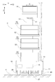
- the article transport vehicle 3 includes a traveling unit 11 that travels on the floor F, a support unit 12 that supports the article W, an irradiation unit 13 that irradiates light, and picking information and storage information.
- the display unit 14 includes a display unit 14 for displaying, and a control unit 15 that controls the traveling unit 11, the irradiation unit 13, and the display unit 14.
- the article transport vehicle 3 includes a battery 16 (see FIG. 3), a bar code reader 17 that reads a bar code displayed on the article W, and an article supported by the support unit 12.
- a weighing unit 18 for measuring the weight of W and an identification information reading unit 19 for reading identification information of the worker M are provided.
- the battery 16 supplies driving power to the traveling unit 11, the irradiation unit 13, the display unit 14, the barcode reader 17, the weighing unit 18, and the identification information reading unit 19.
- the traveling unit 11 includes a pair of traveling wheels 26 arranged in the second direction Y, a driven wheel 27 installed on both sides in the first direction X with respect to the pair of traveling wheels 26, and a traveling that rotationally drives the traveling wheels 26.
- Motor 28 (see FIG. 6).
- the traveling motor 28 is driven by driving power supplied from the battery 16.
- the traveling unit 11 travels forward by rotating both of the pair of traveling wheels 26 in the normal rotation direction by the traveling motor 28, and rotates both of the pair of traveling wheels 26 in the reverse rotation direction by the traveling motor 28. Drive backward.
- the traveling unit 11 performs turning traveling by rotating the pair of traveling wheels 26 at different rotational speeds by the traveling motor 28.
- the direction is defined based on the state in which the article transport vehicle 3 is stopped with the front-rear direction U of the article transport vehicle 3 along the first direction X.
- the front side U1 of the article transport vehicle 3 faces the second direction X2 in the first direction
- the rear side U2 of the article transport vehicle 3 faces the first direction X1 in the first direction.
- the right side faces the storage unit side Y2
- the left side of the article transport vehicle 3 faces the passage side Y1.
- the support 31 is provided upright on the traveling section 11.
- two support bases 32 are supported at a middle position of the support column 31 in the vertical direction Z in a state of being aligned in the vertical direction Z.
- the display unit 14 is supported on the upper end of the column 31.
- a transport container 33 is supported by each of the traveling unit 11 and the two support stands 32, and these transport containers 33 correspond to the support unit 12 that supports the article W.
- the display unit 14 is configured to display picking information and storage information.
- the display unit 14 has a touch panel, and is configured to be operable by the worker M. As shown in FIG. 4, in a state where the article transport vehicle 3 is stopped such that the front side U1 of the article transport vehicle 3 faces the second direction X2 in the first direction, the display unit 14 displays various information.
- the screen is installed so as to face the first side in the first direction X1 and upward.
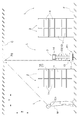
- the irradiation unit 13 irradiates light to an irradiation position P2 which is a position above the article storage shelf 2 (the plurality of storage units 1) and a position corresponding to the own vehicle in a state where the traveling unit 11 is at the set position P1.
- the setting position P1 is set in the work passage L, and above the work passage L is the ceiling of the facility where the picking facilities are installed. Therefore, in a state where the traveling unit 11 is at the set position P1, the light emitted from the irradiation unit 13 directly upward is applied to the ceiling surface C of the ceiling facing downward.
- the position irradiated by the irradiation unit 13 in the state where the traveling unit 11 is at the set position P1 corresponds to the irradiation position P2, that is, the irradiation position P2 is set on the ceiling surface C directly above the own vehicle. Have been.
- the irradiating unit 13 irradiates visible light that the worker M can feel with the naked eye. Further, in the present embodiment, the irradiation position P2 is visible to a worker M who is working in a work path L different from the work path L immediately below the irradiation position P2.
- the irradiating unit 13 includes work information that is information indicating whether the worker M is working on the own vehicle, priority information that is information indicating the priority of the own vehicle, and that the target storage unit 1A is out of stock.
- Storage type information indicating whether the original storage unit 1 (storage unit 1 for taking out the article W in the picking operation) or the storage unit 1 at the storage destination (the storage unit 1 for storing the article W in the storage operation), and an abnormality in the own vehicle.
- Irradiation position P2 and abnormality information indicating that the abnormality has occurred can be applied to the irradiation position P2.
- the irradiation unit 13 displays the storage type information in the color of the light to be irradiated.
- the irradiation unit 13 is configured to be capable of irradiating light of a plurality of colors. It is configured such that the color of the light irradiated to the irradiation position P2 is different between a certain case.
- the irradiation unit 13 displays work information indicating whether or not the worker M is working on the own vehicle with a size of a light irradiation range.
- the irradiation unit 13 is configured to irradiate a wider range when the worker M is not working on the own vehicle than when the worker M is working on the own vehicle. Have been.
- the worker M when the worker M is not working on the own vehicle, the worker irradiates a range (hereinafter, referred to as a large range) having a radius of a first length and is formed by a circle.
- a range formed by a circle having a second length whose radius is shorter than the first length hereinafter, referred to as a small range
- the irradiation unit 13 is configured to display priority information indicating the priority at the blinking interval of the light to be irradiated. For example, it can be configured to indicate that the priority is higher as the light blinking interval becomes shorter. Here, when the priority has two levels, it indicates that the priority is low by continuously irradiating the light, and indicates that the priority is high by irradiating (flashing) the light intermittently. It can be configured as follows. In the present embodiment, a configuration in which the priority is determined in two stages will be described as an example.
- the irradiation unit 13 is configured to display abnormality information indicating that an abnormality has occurred in the vehicle in the shape of light to be irradiated.
- abnormality information indicating that an abnormality has occurred in the vehicle in the shape of light to be irradiated.
- light of a shape and color different from the above-described work information, priority information, and storage type information is emitted.
- the irradiating unit 13 irradiates the area formed in a circle when the work information, the priority information, and the storage type information are described above, whereas the irradiating unit 13 has a rectangular shape when indicating the abnormal information.
- the area formed by is irradiated.
- the irradiation unit 13 also indicates that the abnormality information is obtained by irradiating light of a color (for example, red) different from the color used when indicating the storage type information.
- the identification information reading unit 19 is configured to be able to read the identification information of the worker M held in the identification information holding body 10 of the worker M.
- the identification information reading unit 19 is configured to be able to wirelessly communicate information with the identification information holder 10.
- the identification information reading unit 19 is configured by a reader that reads the identification information stored in the RFID tag.
- the communication range is set so that the identification information of the identification information holding body 10 possessed by M is not read.
- the communication distance which is the radius of such a communication range, is set to, for example, 1 m.
- the identification information reading unit 19 is configured to read the identification information of the identification information holder 10 existing closer than the communication distance set in advance.
- the control unit 15 performs a first traveling control (corresponding to traveling control) for controlling the traveling unit 11 and a second traveling control based on the picking information and the storage information transmitted from the control device H, and a display for controlling the display unit 14.
- a first irradiation control (corresponding to irradiation control) for controlling the irradiation unit 13 so as to irradiate the irradiation position P2 with light in a state where the traveling unit 11 is at the set position P1, and other than the set position P1 during the first traveling control
- the second irradiation control that controls the irradiation unit 13 so that the abnormality information is displayed at the irradiation position P2 when the traveling unit 11 stops at the position indicated by, and the reading control that reads the identification information of the worker M by the identification information reading unit 19.
- And detection control for detecting that the work is completed.
- the first traveling control controls the traveling unit 11 to travel to the set position P1 set corresponding to the target storage unit 1A.
- the set position P1 is on the passage side Y1 with respect to the target storage section 1A, and is set to the first direction first side X1 or the first direction second side X2 in the first direction X.
- the article transport vehicle 3 is stopped at a set position P1 that is set on the passage side Y1 with respect to the target storage unit 1A and on the second side X2 in the first direction.
- the second traveling control is control for controlling the traveling unit 11 so that the traveling unit 11 travels to a work position (not shown).
- the work position corresponds to a place where an operation of lowering the article W supported by the support unit 12 by the picking operation from the article transport vehicle 3 and an operation of supporting the article W stored in the storage unit 1 by the support unit 12 by the storage operation. Is set.
- the control unit 15 interrupts the first traveling control and stops the traveling unit 11. Note that, even when the remaining amount of the battery 16 becomes equal to or less than the set value during the execution of the second traveling control, the second traveling control may be interrupted to stop the traveling unit 11.
- the control unit 15 also interrupts the first traveling control or the second traveling control when an event that the traveling unit 11 cannot continue normal traveling due to the presence of an obstacle or a failure of the traveling unit 11 occurs. To stop the traveling unit 11.
- the display control indicates number information indicating the number of articles W to be put into and taken out of the target storage section 1A, type information indicating the type of the article W to be put into and taken out of the target storage section 1A, and indicating the position of the target storage section 1A.
- the display unit 14 is controlled so that the display unit 14 displays the position information, the storage type information, and the container information indicating the container into which the article W is put in and out of the plurality of transport containers 33.
- the control unit 15 displays, on the display unit 14, the position of the target storage unit 1A, and the number information and type information of the articles W to be taken out from the target storage unit 1A.
- a character string or a mark indicating the picking operation is displayed on the display unit 14 as the storage type information.
- the control unit 15 displays the position of the target storage unit 1A and the number information and the type information of the articles W stored in the target storage unit 1A on the display unit 14.
- the display unit 14 displays a character string or a mark indicating the storage operation as the storage type information.
- the control unit 15 is configured to be able to determine the type of the article W from which the barcode has been read by reading the barcode of the article W with the barcode reader 17.
- the control unit 15 determines that the type of the article W determined by reading the barcode of the article W with the barcode reader 17 is the article W to be loaded and unloaded on the support unit 12, and the determined article W When the type and the type of the article W indicated by the type information are different, information indicating an error is displayed on the display unit 14.
- control unit 15 stores weight information indicating the weight of the article W, and the weighing unit 18 can separately measure the weight of the plurality of support units 12 or the total weight of the plurality of support units 12. Is configured to be weighable.
- the control unit 15 determines, based on the change in the weight measured by the weighing unit 18 and the weight information of the article W to be supported by the support unit 12, the number of articles W of the type indicated by the type information specified by the number indicated by the number information. It is determined whether or not the component 12 has been correctly placed on and dismounted from the unit 12. When the control unit 15 determines that a different type of article W has been placed on or off the support unit 12, or that the number of articles W different from the number indicated by the number information is placed on or off the support unit 12. If it is determined that the article W has been loaded or unloaded on a support section 12 different from the designated support section 12, information indicating an error is displayed on the display section 14.
- the control unit 15 determines that the type of the article W determined based on the information read by the barcode reader 17 matches the type of the article W indicated by the type information, and the type of the article W indicated by the type information. If it is determined that W has been loaded and unloaded on the specified number of support portions 12 indicated by the number information, it is determined that the article W has been correctly loaded and unloaded on the support portion 12. More specifically, the control unit 15 determines that the article W is correctly supported on the support unit 12 in the detection control based on the picking information, and correctly removes the article W from the support unit 12 in the detection control based on the storage information. It is determined that it has been performed. As described above, the control unit 15, the barcode reader 17, and the weighing unit 18 constitute the detection unit 35 that detects that the article W taken out of the target storage unit 1A is correctly supported by the support unit 12. I have.
- the control unit 15 causes the identification information reading unit 19 to read the identification information of the identification information holder 10 of the worker M existing within the communication range, as the bar code reader 17 reads the bar code. Then, the control unit 15 causes the traveling unit 11 to travel to the set position P1 by the first traveling control, and then keeps the worker M until the identification information reading unit 19 reads the identification information of the worker M by the reading control. It is determined that the vehicle is not working (it is not working), and after the identification information reading unit 19 reads the identification information of the worker M by the reading control, it is determined that the vehicle is correctly loaded and unloaded by the detection control. Until then, it is determined that the worker M is working on the own vehicle (work is in progress). As described above, the control unit 15 determines whether the worker M is working on the own vehicle based on the detection information of the identification information reading unit 19.
- the control unit 15 measures an elapsed time after the first traveling control ends, and the elapsed time is measured. If the value is equal to or less than the set value, the priority of the own vehicle is determined to be low, and if the elapsed time exceeds the set value, the priority of the own vehicle is determined to be high. That is, in the present embodiment, the priority determination condition for determining the priority is based on the standby time of the own vehicle at the current set position P1, and the necessity of hurrying the work of the worker M as the standby time becomes longer. This is a condition for determining a higher priority as a higher priority. In this example, since the priority is determined in two stages, whether the priority is “high” or “low” is determined based on whether the standby time exceeds a set value.
- the first irradiation control controls the irradiation unit 13 so as to irradiate the irradiation position P2 with light.
- the control unit 15 controls the irradiation unit 13 to display work information at the irradiation position P2 in the first irradiation control according to whether or not the worker M is working on the own vehicle.
- the control unit 15 irradiates a large area in a state where the worker M determines that the worker M is not working on the own vehicle based on the detection information of the identification information reading unit 19.
- the irradiation unit 13 In a state where the light is emitted from the irradiation unit 13 and the worker M determines that the vehicle is working on the own vehicle, the irradiation unit 13 emits light so as to irradiate a small area. 13 is controlled.
- control unit 15 controls the irradiation unit 13 to display the priority information at the irradiation position P2 in the first irradiation control according to the priority determined based on the above-described priority determination condition. .
- the control unit 15 hasten the work of the worker M at the current set position P1 in a state where it is determined that the priority is low according to the waiting time of the own vehicle at the current set position P1. In the state where the necessity is determined to be low and the light is continuously emitted from the irradiation unit 13 and the priority is determined to be high, it is highly necessary to urgently work the worker M at the current set position P1.
- the irradiation unit 13 is controlled so that the light is intermittently emitted from the irradiation unit 13 upon determination.
- the control unit 15 causes the irradiation unit 13 to display the storage type information corresponding to whether the target storage unit 1A is the storage unit 1 of the delivery source or the storage unit 1 of the storage destination at the irradiation position P2.
- Control changes the color of the light irradiated by the irradiation unit 13 in a case where the first irradiation control is executed based on the picking information and in a case where the first irradiation control is executed based on the storage information. By making them different, the irradiation unit 13 is controlled so that the storage type information is displayed at the irradiation position P2.
- the second irradiation control controls the irradiation unit 13 so as to irradiate the irradiation position P2 with light, similarly to the first irradiation control.
- the first irradiation control is performed in a state where the traveling unit 11 is at the set position P1 set for the target storage unit 1A, whereas the second irradiation control is set for the target storage unit 1A.
- the process is executed in a state where the traveling unit 11 is located at a position other than the set position P1. That is, the second irradiation control is executed when the traveling unit 11 abnormally stops before reaching the set position P1 set for the target storage unit 1A during the execution of the first traveling control.
- the control unit 15 when an event that the normal traveling cannot be continued occurs during the execution of the first traveling control, the control unit 15 abnormally stops the traveling unit 11. As such an event, for example, when it is impossible to continue the first traveling control by the traveling unit 11 due to being blocked by a certain obstacle, it becomes difficult to continue traveling to the traveling unit 11. There may be a case where a failure occurs, or a case where the first traveling control is interrupted due to the remaining charge of the battery 16 being equal to or less than the set value, and the traveling unit 11 stops. Then, when the control unit 15 determines that the traveling unit 11 has abnormally stopped at a position other than the set position P1, the control unit 15 executes the second irradiation control.
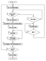
- the control unit 15 When receiving the picking information or the storage information from the upper controller, the control unit 15 starts the first traveling control (S1), and the target storage unit 1A (the plurality of target storage units 1A) specified by the picking information or the storage information.
- the traveling unit 11 arrives at the set position P1 corresponding to one of them (if one is designated), the first traveling control ends (S2, S3).
- the control unit 15 starts the display control and the first irradiation control in a state where the traveling unit 11 is located at the set position P1 (S4).
- the control unit 15 executes the reading control in accordance with the reading of the barcode of the article W by the barcode reader 17 (S5), and then completes the operation at one set position P1 by the detection control (the supporting unit). It is determined whether or not the article W has been correctly loaded and unloaded on the device 12 (S6, S7). When the work at one set position P1 is completed (S7: Yes), the display control and the first irradiation control are ended (S8). If the work has been completed for all of the plurality of target storage sections 1A specified by the picking information and storage information (S9: Yes), the second travel control is executed (S10).
- the following first travel control is started so that the travel section 11 travels to the set position P1 corresponding to the target storage section 1A for which the work has not been completed (S1).
- the control unit 15 continues the first traveling control. If the above-described event occurs during the execution and the traveling unit 11 abnormally stops (S11: Yes), the second irradiation control is executed (S12). Thereafter, the control unit 15 continues the second irradiation control (S12) until the traveling unit 11 recovers from the abnormal stop state (S13: No), and when the traveling unit 11 recovers from the abnormal stop state ( S13: Yes), the first traveling control is restarted (S1).
- the control unit 15 starts the first irradiation control as the execution of the first traveling control ends as described above, and determines that the operation at one set position P1 is completed by the detection control, and the second traveling Before executing the control, the first irradiation control is ended.
- the first irradiation control as shown in the flowchart of FIG. 8, first, light of a color corresponding to the storage type is continuously irradiated to a large range (S21).
- the identification information reading unit 19 reads the identification information by executing the reading control in a state where the light irradiation range is large (S22: No, S24: Yes)
- the worker M It is determined that the work is being performed, and the light irradiation range is changed from the large range to the small range (S25). If the set time has elapsed after the execution of the first traveling control is completed in a state where the light is continuously emitted (S23: No, S26: Yes), it is determined that the priority of the own vehicle is high. Then, the light irradiation interval is changed from the state of continuous irradiation to the state of intermittent irradiation (S27).
- the irradiation position P2 is set to the ceiling surface C, but the irradiation position P2 may be changed as appropriate.
- an irradiation target may be installed above a plurality of storage units 1 (article storage shelves 2), and an irradiation position P2 may be set for the irradiation target.
- the irradiation position P2 may be set on an installation object such as a beam installed in the picking facility.
- the work information, the priority information, the storage type information, and the abnormality information are displayed at the irradiation position P2, but the work information, the priority information, the storage type information, and the abnormality information are displayed at the irradiation position P2. It is good also as composition which displays only some of them. Further, information other than the work information, the priority information, the storage type information, and the abnormality information may be displayed at the irradiation position P2.
- the work information is displayed by the size of the light irradiation range at the irradiation position P2
- the priority information is displayed by the flashing interval of the light
- the storage type information is displayed by the color of the light
- the abnormality information is displayed.
- the display method of each information is not limited to this. That is, the configuration may be such that the work information is displayed in the blinking interval of the light, the color of the light, or the shape of the light, or the priority information may be displayed in the size of the irradiation range of the light, the color of the light, or the shape of the light.
- the storage type information may be displayed in the form of the size of the light irradiation range, the light blinking interval, and the light shape, or the abnormal information may be displayed as the light blinking interval, the size of the light irradiation range, the light shape, and the like. It may be configured to display one of the colors. Alternatively, such information may be displayed as a character string, a mark, or the like, may be displayed as light intensity (brightness), or may be displayed as to whether or not light has been irradiated. Further, a configuration may be adopted in which a plurality of various display methods described above are combined to display each information.
- the priority is determined based on the standby time of the vehicle at the current set position P1, but the priority determination condition may be changed as appropriate. Specifically, the priority may be determined so that the priority increases as the time until the shipping deadline of the article W supported by the support unit 12 decreases. In addition, the number of the set positions P1 at which the own vehicle is determined to be heading thereafter (the number of the target storage units 1A whose work has not been completed among the plurality of target storage units 1A specified by the picking information or the storage information). The priority may be determined so that the priority increases as the number increases. The priority may be determined so that the priority increases as the remaining charge of the battery 16 decreases.
- the priority may be determined based on a combination of two or more of the waiting time of the vehicle, the shipping deadline of the article W, the number of the set positions P1 heading thereafter, and the remaining charge of the battery 16. .
- the priority may be determined using conditions other than these.
- whether or not the worker M is working on the own vehicle is determined based on the identification information of the identification information reading unit 19; however, the worker M is working on the own vehicle.
- the information source for determining whether or not the information may be changed as appropriate. Specifically, based on the read information of the barcode reader 17 and the weighing information of the weighing unit 18, it may be determined whether or not the worker M is working on the own vehicle. In this case, based on whether the barcode reader 17 reads the barcode of the article W and whether the weight measured by the weighing unit 18 fluctuates in a state where the article transport vehicle 3 is at the set position P1. It is preferable to determine whether the worker M is working on the own vehicle.
- the irradiation unit 13 irradiates the light directly upward, but the irradiation unit 13 may irradiate the light obliquely upward.
- the storage unit 1 at the storage destination is also the target storage unit 1A, but only the storage unit 1 at the warehouse may be the target storage unit 1A.
- the irradiation control and the display control are started with the end of the traveling control.
- one or both of the irradiation control and the display control are started before the traveling control ends.
- the display control may be started at the same time as the start of the travel control or during the execution of the travel control, or the irradiation control may be started during the execution of the travel control.
- the irradiation unit 13 is controlled to execute the traveling control (the traveling unit 11 is traveling) or the traveling control is terminated (the traveling unit 11 stops at the set position P1).
- the irradiating unit 13 irradiates visible light, but the irradiating unit 13 may irradiate invisible light (ultraviolet light, infrared light, or the like).
- invisible light ultraviolet light, infrared light, or the like.
- a member including a phosphor that emits light by invisible light may be provided at the irradiation position P2, or a paint including the phosphor may be applied.
- the article transport vehicle includes a traveling unit that travels to a set position set corresponding to each of the plurality of storage units that store the articles, a support unit that supports the articles, an irradiation unit that emits light, and the traveling unit. And a control unit that controls the irradiation unit, wherein the storage unit in which the article to be supported by the support unit is stored is set as a target storage unit, and the control unit is set corresponding to the target storage unit. Traveling control for controlling the traveling unit so that the traveling unit travels to the set position, and corresponding to the own vehicle at a position above the plurality of storage units in a state where the traveling unit is at the set position. And irradiation control for controlling the irradiation unit so as to irradiate the irradiation position which is the position to be irradiated with light.
- the control unit executes the traveling control, so that the traveling unit travels to the set position, and the control unit executes the irradiation control, so that the irradiation unit emits light to the irradiation position.
- This irradiation position is a position above the plurality of storage units and a position corresponding to the own vehicle, so that even an operator who is away from the article transport vehicle or a worker who is in a place separated by the storage unit, etc. It is possible to recognize that the article transport vehicle that needs to perform the picking operation is at the set position. For this reason, the worker can easily recognize that it is necessary to perform the picking operation on the article transport vehicle, and can easily perform the picking operation.
- the irradiation unit is configured to be able to irradiate the irradiation position with work information that is information indicating whether or not the worker is working on the own vehicle, and the control unit is configured so that the worker
- the irradiation unit is controlled so that the work information is displayed at the irradiation position depending on whether or not the work is being performed.
- the control unit executes the irradiation control, whereby the work information is displayed at the irradiation position. For this reason, the worker who is not working on the article transport vehicle that is irradiating the irradiation position with light, confirms the light that has been irradiated on the irradiation position, and then checks the article transport vehicle that is irradiating the light with the light. On the other hand, it can be determined whether or not another worker is working. Therefore, even when the worker is away from the article transport vehicle, it is possible to determine whether or not the worker himself / herself needs to perform an operation on the article transport vehicle, thereby facilitating the picking operation.
- the control information includes an identification information reading unit that reads the identification information of the worker held in the identification information holding body of the worker, Preferably, the unit determines whether or not the worker is working on the own vehicle based on the detection information of the identification information reading unit.
- the irradiating unit is configured to be able to irradiate the irradiating position with priority information that is information indicating a priority of the own vehicle, and the control unit is configured to determine a priority determined based on a predetermined priority determining condition.
- the irradiation unit is controlled so as to display the priority information at the irradiation position according to the degree.
- the worker can recognize the priority of the work on the article transport vehicle corresponding to the light by confirming the light irradiated to the irradiation position. For this reason, it is possible for the operator to preferentially perform the work on the article transport vehicle with a high priority. Thus, it is possible to avoid delaying the work on the article transport vehicle with high priority, and to facilitate the picking work.
- the priority determination condition is a shipping deadline of an article to be supported by the support portion, a waiting time of the own vehicle at the current set position, the number of the set positions where the own vehicle is determined to be headed thereafter, And, when a battery that supplies driving power to at least one of the traveling unit, the irradiation unit, and the control unit is provided, based on at least one of the remaining charge amount of the battery. It is preferable that the condition is such that the priority is determined to be higher in descending order of necessity of urgently performing the work of the worker at the current set position.
- an article transport vehicle that transports an article whose expiration date is approaching, an article transport vehicle that has a long waiting time at the current set position, an article transport vehicle that has a large number of set positions heading thereafter, and a battery
- An article transport vehicle with a small remaining charge can be a high priority article transport vehicle. Therefore, it is possible for the operator to give priority to the work on these article transport vehicles.
- the storage unit at the storage destination storing the articles supported by the support unit is preferably the target storage unit. It is.
- the irradiation section may be configured such that the target storage section is the storage section at the delivery source or the storage section at the storage destination.
- the storage unit is configured to be capable of irradiating light so as to display the storage type information indicating the unit at the irradiation position.
- the control unit may be configured such that the target storage unit is the storage unit of the delivery source or the storage destination.
- the irradiation unit is controlled so that the storage type information corresponding to the storage unit is displayed at the irradiation position.
- the work performed on the target storage unit is performed by taking out the object from the target storage unit or storing the object in the target storage unit. Can be recognized in advance by the operator. Therefore, even when there is a possibility that both the work of taking out the article from the target storage section and the work of storing the article in the target storage section, these works can be facilitated.
- the irradiation position is set on a ceiling surface directly above the own vehicle.
- the configuration of the irradiation unit can be simplified and the control of the irradiation unit in the irradiation control can be simplified.
- the light from the irradiating section is irradiated on the ceiling surface, it is easy for an operator to visually recognize the light.
- the irradiation unit is configured to be able to irradiate the irradiation position with abnormality information indicating that an abnormality has occurred in the own vehicle, and the control unit is configured to execute the traveling unit at a position other than the set position during the traveling control. When is stopped, it is preferable to execute second irradiation control for controlling the irradiation unit so as to display the abnormality information at the irradiation position.
- the worker can recognize that the article transport vehicle has abnormally stopped at a position other than the set position by checking the light irradiated to the irradiation position. Therefore, the operator can quickly find the article transport vehicle in which the abnormality has occurred. As a result, the article transport vehicle in which the abnormality has occurred can be quickly restored.
- the technology according to the present disclosure can be used for an article transport vehicle provided with a support section that supports an article.
- storage section 1A target storage section 10: identification information holding body 11: traveling section 12: support section 13: irradiation section 15: control section 16: battery 19: identification information reading section C: ceiling surface M: worker P1: Set position P2: Irradiation position W: Article
Landscapes
- Engineering & Computer Science (AREA)
- Mechanical Engineering (AREA)
- Physics & Mathematics (AREA)
- General Physics & Mathematics (AREA)
- Theoretical Computer Science (AREA)
- Health & Medical Sciences (AREA)
- Electromagnetism (AREA)
- General Health & Medical Sciences (AREA)
- Toxicology (AREA)
- Artificial Intelligence (AREA)
- Computer Vision & Pattern Recognition (AREA)
- Warehouses Or Storage Devices (AREA)
Abstract
L'invention concerne un véhicule de transport d'articles (3) comprenant : une partie de déplacement (11) qui se déplace vers une position prédéfinie (P1) qui est réglée de façon à correspondre à chaque contenant parmi une pluralité de contenants (1) dans laquelle des articles sont stockés ; une partie de support (12) qui supporte les articles ; une unité d'irradiation (13) qui irradie de la lumière ; et une unité de commande qui commande la partie de déplacement (11) et l'unité d'irradiation (13). En utilisant le contenant (1) dans lequel sont stockés les articles devant être supportés par la partie de support (12), en tant que contenant cible (1A), l'unité de commande effectue une commande de déplacement pour amener la partie de déplacement (11) à se déplacer vers la position prédéfinie (P1) réglée de façon correspondante au contenant cible (1A) et une commande d'irradiation pour commander l'unité d'irradiation (13) pour irradier avec de la lumière une position d'irradiation (P2), qui est une position au-dessus de la pluralité de contenants (1) et correspondant au véhicule, dans un état dans lequel la partie de déplacement (11) est située à la position prédéfinie (P1).
Priority Applications (6)
| Application Number | Priority Date | Filing Date | Title |
|---|---|---|---|
| US17/254,453 US11542098B2 (en) | 2018-06-22 | 2019-06-14 | Article transport vehicle |
| KR1020207035433A KR20210021973A (ko) | 2018-06-22 | 2019-06-14 | 물품 반송차 |
| CA3104451A CA3104451A1 (fr) | 2018-06-22 | 2019-06-14 | Vehicule de transport d'articles |
| EP19822777.9A EP3812311A4 (fr) | 2018-06-22 | 2019-06-14 | Véhicule de transport d'articles |
| CN202210601126.9A CN114772143B (zh) | 2018-06-22 | 2019-06-14 | 物品搬运车 |
| CN201980038266.6A CN112203952B (zh) | 2018-06-22 | 2019-06-14 | 物品搬运车 |
Applications Claiming Priority (2)
| Application Number | Priority Date | Filing Date | Title |
|---|---|---|---|
| JP2018119080A JP6841270B2 (ja) | 2018-06-22 | 2018-06-22 | 物品搬送車 |
| JP2018-119080 | 2018-06-22 |
Publications (1)
| Publication Number | Publication Date |
|---|---|
| WO2019244787A1 true WO2019244787A1 (fr) | 2019-12-26 |
Family
ID=68983858
Family Applications (1)
| Application Number | Title | Priority Date | Filing Date |
|---|---|---|---|
| PCT/JP2019/023634 WO2019244787A1 (fr) | 2018-06-22 | 2019-06-14 | Véhicule de transport d'articles |
Country Status (8)
| Country | Link |
|---|---|
| US (1) | US11542098B2 (fr) |
| EP (1) | EP3812311A4 (fr) |
| JP (1) | JP6841270B2 (fr) |
| KR (1) | KR20210021973A (fr) |
| CN (2) | CN114772143B (fr) |
| CA (1) | CA3104451A1 (fr) |
| TW (1) | TWI826470B (fr) |
| WO (1) | WO2019244787A1 (fr) |
Cited By (2)
| Publication number | Priority date | Publication date | Assignee | Title |
|---|---|---|---|---|
| JP6886094B1 (ja) * | 2020-08-20 | 2021-06-16 | 上海姜歌机器人有限公司Django Robotics Shanghai Co.,Ltd. | ピッキングロボットについてのピッキングお知らせ方法及びピッキングロボット |
| JP2022100272A (ja) * | 2020-12-23 | 2022-07-05 | 炬星科技(深▲せん▼)有限公司 | マンマシンインタラクションの待ち時間を短縮する方法、機器及び記憶媒体 |
Families Citing this family (3)
| Publication number | Priority date | Publication date | Assignee | Title |
|---|---|---|---|---|
| US9008884B2 (en) | 2010-12-15 | 2015-04-14 | Symbotic Llc | Bot position sensing |
| TWI622540B (zh) * | 2011-09-09 | 2018-05-01 | 辛波提克有限責任公司 | 自動化儲存及取放系統 |
| JP7468482B2 (ja) * | 2021-09-03 | 2024-04-16 | 株式会社ダイフク | 物品搬送車 |
Citations (7)
| Publication number | Priority date | Publication date | Assignee | Title |
|---|---|---|---|---|
| JPH07309409A (ja) * | 1994-05-13 | 1995-11-28 | Toyo Kanetsu Kk | ピッキング指示方法及び装置 |
| JPH08244920A (ja) * | 1995-03-15 | 1996-09-24 | Omron Corp | ピッキング装置 |
| JP2000142927A (ja) * | 1998-11-05 | 2000-05-23 | Ishida Co Ltd | 商品仕分けシステム |
| JP2008247546A (ja) | 2007-03-30 | 2008-10-16 | Daifuku Co Ltd | ピッキング作業用台車およびピッキング作業用台車を備えたピッキング設備 |
| JP2012048531A (ja) * | 2010-08-27 | 2012-03-08 | Kanto Auto Works Ltd | 作業監視システム |
| WO2018047355A1 (fr) * | 2016-09-12 | 2018-03-15 | 株式会社アイオイ・システム | Dispositif d'aide au prélèvement de stock |
| JP2018507830A (ja) * | 2015-02-12 | 2018-03-22 | ワイズ,メロニー | 注文実行においてロボットを使用して人間を支援するシステム及び方法 |
Family Cites Families (13)
| Publication number | Priority date | Publication date | Assignee | Title |
|---|---|---|---|---|
| TWI228098B (en) * | 2003-04-30 | 2005-02-21 | Chunghwa Picture Tubes Ltd | Manual guided vehicle capable of working on a rail |
| US8955989B2 (en) * | 2012-01-23 | 2015-02-17 | Spectra Logic Corporation | Systems for and methods of creating a visual display associated with a data storage library robot |
| US8918202B2 (en) * | 2012-08-21 | 2014-12-23 | Amazon Technologies, Inc. | Controlling mobile drive units with active markers |
| US9809384B2 (en) * | 2014-11-24 | 2017-11-07 | Amazon Technologies, Inc. | Inventory system with efficient operator handling of inventory items |
| US9656806B2 (en) * | 2015-02-13 | 2017-05-23 | Amazon Technologies, Inc. | Modular, multi-function smart storage containers |
| US9487356B1 (en) | 2015-03-02 | 2016-11-08 | Amazon Technologies, Inc. | Managing low-frequency inventory items in a fulfillment center |
| CN104803142B (zh) * | 2015-03-05 | 2017-04-26 | 北京融安特智能科技有限公司 | 一种可移动的档案智能管理平台 |
| JP6164703B2 (ja) * | 2015-03-19 | 2017-07-19 | Necエンジニアリング株式会社 | 作業実績収集システム、作業実績収集方法及びプログラム |
| CN204895275U (zh) * | 2015-07-13 | 2015-12-23 | 王邑都 | 汽车停车位置指示器 |
| US9688472B1 (en) * | 2015-12-10 | 2017-06-27 | Amazon Technologies, Inc. | Mobile robot manipulator |
| CN106144510B (zh) * | 2016-08-25 | 2018-11-27 | 深圳市泽宇智能工业科技有限公司 | 供料机构及包含供料机构的柔性生产线 |
| CN206217740U (zh) * | 2016-10-08 | 2017-06-06 | 北京汽车股份有限公司 | 带有车辆位置指示装置的汽车 |
| CN107840059B (zh) * | 2017-11-30 | 2023-11-28 | 上海诺力智能科技有限公司 | 一种双向仓储自动取料机 |
-
2018
- 2018-06-22 JP JP2018119080A patent/JP6841270B2/ja active Active
-
2019
- 2019-06-14 CN CN202210601126.9A patent/CN114772143B/zh active Active
- 2019-06-14 KR KR1020207035433A patent/KR20210021973A/ko unknown
- 2019-06-14 US US17/254,453 patent/US11542098B2/en active Active
- 2019-06-14 EP EP19822777.9A patent/EP3812311A4/fr active Pending
- 2019-06-14 CN CN201980038266.6A patent/CN112203952B/zh active Active
- 2019-06-14 WO PCT/JP2019/023634 patent/WO2019244787A1/fr active Application Filing
- 2019-06-14 CA CA3104451A patent/CA3104451A1/fr active Pending
- 2019-06-19 TW TW108121265A patent/TWI826470B/zh active
Patent Citations (7)
| Publication number | Priority date | Publication date | Assignee | Title |
|---|---|---|---|---|
| JPH07309409A (ja) * | 1994-05-13 | 1995-11-28 | Toyo Kanetsu Kk | ピッキング指示方法及び装置 |
| JPH08244920A (ja) * | 1995-03-15 | 1996-09-24 | Omron Corp | ピッキング装置 |
| JP2000142927A (ja) * | 1998-11-05 | 2000-05-23 | Ishida Co Ltd | 商品仕分けシステム |
| JP2008247546A (ja) | 2007-03-30 | 2008-10-16 | Daifuku Co Ltd | ピッキング作業用台車およびピッキング作業用台車を備えたピッキング設備 |
| JP2012048531A (ja) * | 2010-08-27 | 2012-03-08 | Kanto Auto Works Ltd | 作業監視システム |
| JP2018507830A (ja) * | 2015-02-12 | 2018-03-22 | ワイズ,メロニー | 注文実行においてロボットを使用して人間を支援するシステム及び方法 |
| WO2018047355A1 (fr) * | 2016-09-12 | 2018-03-15 | 株式会社アイオイ・システム | Dispositif d'aide au prélèvement de stock |
Non-Patent Citations (1)
| Title |
|---|
| See also references of EP3812311A4 |
Cited By (4)
| Publication number | Priority date | Publication date | Assignee | Title |
|---|---|---|---|---|
| JP6886094B1 (ja) * | 2020-08-20 | 2021-06-16 | 上海姜歌机器人有限公司Django Robotics Shanghai Co.,Ltd. | ピッキングロボットについてのピッキングお知らせ方法及びピッキングロボット |
| JP2022035937A (ja) * | 2020-08-20 | 2022-03-04 | 上海姜歌机器人有限公司 | ピッキングロボットについてのピッキングお知らせ方法及びピッキングロボット |
| JP2022100272A (ja) * | 2020-12-23 | 2022-07-05 | 炬星科技(深▲せん▼)有限公司 | マンマシンインタラクションの待ち時間を短縮する方法、機器及び記憶媒体 |
| JP7261859B2 (ja) | 2020-12-23 | 2023-04-20 | 炬星科技(深▲せん▼)有限公司 | マンマシンインタラクションの待ち時間を短縮する方法、機器及び記憶媒体 |
Also Published As
| Publication number | Publication date |
|---|---|
| US20210221617A1 (en) | 2021-07-22 |
| JP2019218209A (ja) | 2019-12-26 |
| CN112203952A (zh) | 2021-01-08 |
| EP3812311A1 (fr) | 2021-04-28 |
| CA3104451A1 (fr) | 2019-12-26 |
| US11542098B2 (en) | 2023-01-03 |
| CN112203952B (zh) | 2022-07-19 |
| KR20210021973A (ko) | 2021-03-02 |
| CN114772143B (zh) | 2024-03-19 |
| TWI826470B (zh) | 2023-12-21 |
| TW202012281A (zh) | 2020-04-01 |
| JP6841270B2 (ja) | 2021-03-10 |
| EP3812311A4 (fr) | 2022-08-03 |
| CN114772143A (zh) | 2022-07-22 |
Similar Documents
| Publication | Publication Date | Title |
|---|---|---|
| WO2019244787A1 (fr) | Véhicule de transport d'articles | |
| JP5729606B2 (ja) | 物品処理設備 | |
| KR20180091042A (ko) | 모터 구동 카트를 사용하는 창고 자동화 시스템들 및 방법들 | |
| JP2010044530A (ja) | 搬送ロボットシステム | |
| CN108910560A (zh) | 一种工业装载车辆定位装置和方法 | |
| WO2019244768A1 (fr) | Véhicule de transport d'articles | |
| JPS6392506A (ja) | 物品収集設備 | |
| CN112119024B (zh) | 物品输送车 | |
| KR102119268B1 (ko) | 이송 대상물의 자동이송장치 및 자동이송방법 | |
| KR102225263B1 (ko) | 스마트 카트 | |
| JP2017007847A (ja) | 搬送台車 | |
| JP5170190B2 (ja) | 搬送車システム | |
| JPH07267347A (ja) | 吊り下げ搬送装置における荷の移載位置制御装置 | |
| WO2024100960A1 (fr) | Installation de transport d'articles | |
| JP2005225582A (ja) | 物品処理設備 | |
| JP3505283B2 (ja) | 電動台車の荷位置制御装置 | |
| JPH08161045A (ja) | 電動台車の停止位置制御装置 | |
| JP4314520B2 (ja) | 物品移載装置 | |
| JPH08211938A (ja) | 電動台車の停止位置制御装置 | |
| JPH08263139A (ja) | 電動台車の停止位置制御装置 | |
| JPH10101215A (ja) | 走行台車の走行制御装置 | |
| JPS6371002A (ja) | 物品仕分け設備 | |
| JP2009263054A (ja) | 物品搬送装置 | |
| JPH092609A (ja) | 電動台車の荷位置制御装置 |
Legal Events
| Date | Code | Title | Description |
|---|---|---|---|
| 121 | Ep: the epo has been informed by wipo that ep was designated in this application |
Ref document number: 19822777 Country of ref document: EP Kind code of ref document: A1 |
|
| ENP | Entry into the national phase |
Ref document number: 3104451 Country of ref document: CA |
|
| NENP | Non-entry into the national phase |
Ref country code: DE |
|
| WWE | Wipo information: entry into national phase |
Ref document number: 2019822777 Country of ref document: EP |