WO2019244787A1 - Article transport vehicle - Google Patents
Article transport vehicle Download PDFInfo
- Publication number
- WO2019244787A1 WO2019244787A1 PCT/JP2019/023634 JP2019023634W WO2019244787A1 WO 2019244787 A1 WO2019244787 A1 WO 2019244787A1 JP 2019023634 W JP2019023634 W JP 2019023634W WO 2019244787 A1 WO2019244787 A1 WO 2019244787A1
- Authority
- WO
- WIPO (PCT)
- Prior art keywords
- unit
- irradiation
- control
- storage
- traveling
- Prior art date
Links
Images


Classifications
-
- B—PERFORMING OPERATIONS; TRANSPORTING
- B65—CONVEYING; PACKING; STORING; HANDLING THIN OR FILAMENTARY MATERIAL
- B65G—TRANSPORT OR STORAGE DEVICES, e.g. CONVEYORS FOR LOADING OR TIPPING, SHOP CONVEYOR SYSTEMS OR PNEUMATIC TUBE CONVEYORS
- B65G1/00—Storing articles, individually or in orderly arrangement, in warehouses or magazines
- B65G1/02—Storage devices
- B65G1/04—Storage devices mechanical
- B65G1/137—Storage devices mechanical with arrangements or automatic control means for selecting which articles are to be removed
- B65G1/1373—Storage devices mechanical with arrangements or automatic control means for selecting which articles are to be removed for fulfilling orders in warehouses
- B65G1/1375—Storage devices mechanical with arrangements or automatic control means for selecting which articles are to be removed for fulfilling orders in warehouses the orders being assembled on a commissioning stacker-crane or truck
-
- B—PERFORMING OPERATIONS; TRANSPORTING
- B65—CONVEYING; PACKING; STORING; HANDLING THIN OR FILAMENTARY MATERIAL
- B65G—TRANSPORT OR STORAGE DEVICES, e.g. CONVEYORS FOR LOADING OR TIPPING, SHOP CONVEYOR SYSTEMS OR PNEUMATIC TUBE CONVEYORS
- B65G1/00—Storing articles, individually or in orderly arrangement, in warehouses or magazines
- B65G1/02—Storage devices
- B65G1/04—Storage devices mechanical
- B65G1/137—Storage devices mechanical with arrangements or automatic control means for selecting which articles are to be removed
- B65G1/1373—Storage devices mechanical with arrangements or automatic control means for selecting which articles are to be removed for fulfilling orders in warehouses
-
- B—PERFORMING OPERATIONS; TRANSPORTING
- B65—CONVEYING; PACKING; STORING; HANDLING THIN OR FILAMENTARY MATERIAL
- B65G—TRANSPORT OR STORAGE DEVICES, e.g. CONVEYORS FOR LOADING OR TIPPING, SHOP CONVEYOR SYSTEMS OR PNEUMATIC TUBE CONVEYORS
- B65G1/00—Storing articles, individually or in orderly arrangement, in warehouses or magazines
- B65G1/02—Storage devices
- B65G1/04—Storage devices mechanical
- B65G1/0492—Storage devices mechanical with cars adapted to travel in storage aisles
-
- B—PERFORMING OPERATIONS; TRANSPORTING
- B65—CONVEYING; PACKING; STORING; HANDLING THIN OR FILAMENTARY MATERIAL
- B65G—TRANSPORT OR STORAGE DEVICES, e.g. CONVEYORS FOR LOADING OR TIPPING, SHOP CONVEYOR SYSTEMS OR PNEUMATIC TUBE CONVEYORS
- B65G1/00—Storing articles, individually or in orderly arrangement, in warehouses or magazines
- B65G1/02—Storage devices
- B65G1/04—Storage devices mechanical
- B65G1/137—Storage devices mechanical with arrangements or automatic control means for selecting which articles are to be removed
- B65G1/1371—Storage devices mechanical with arrangements or automatic control means for selecting which articles are to be removed with data records
-
- G—PHYSICS
- G06—COMPUTING; CALCULATING OR COUNTING
- G06K—GRAPHICAL DATA READING; PRESENTATION OF DATA; RECORD CARRIERS; HANDLING RECORD CARRIERS
- G06K19/00—Record carriers for use with machines and with at least a part designed to carry digital markings
- G06K19/06—Record carriers for use with machines and with at least a part designed to carry digital markings characterised by the kind of the digital marking, e.g. shape, nature, code
- G06K19/06009—Record carriers for use with machines and with at least a part designed to carry digital markings characterised by the kind of the digital marking, e.g. shape, nature, code with optically detectable marking
-
- G—PHYSICS
- G06—COMPUTING; CALCULATING OR COUNTING
- G06K—GRAPHICAL DATA READING; PRESENTATION OF DATA; RECORD CARRIERS; HANDLING RECORD CARRIERS
- G06K7/00—Methods or arrangements for sensing record carriers, e.g. for reading patterns
- G06K7/10—Methods or arrangements for sensing record carriers, e.g. for reading patterns by electromagnetic radiation, e.g. optical sensing; by corpuscular radiation
- G06K7/14—Methods or arrangements for sensing record carriers, e.g. for reading patterns by electromagnetic radiation, e.g. optical sensing; by corpuscular radiation using light without selection of wavelength, e.g. sensing reflected white light
Definitions
- the present invention relates to an article transport vehicle provided with a support for supporting an article.
- Patent Document 1 Japanese Patent Application Laid-Open No. 2008-247546
- the article transport vehicle (picking work cart) of Patent Document 1 is provided in a picking facility.
- the article transport vehicle is moved by a push-pull operation of an operator to move the article transport vehicle near the storage section (article storage section 5) of the target storage shelf (3), and articles are moved from the storage section of the storage shelf.
- a picking operation is performed in which the picked-up article is taken out and supported by the support section (container 8) of the article transport vehicle.
- the article carrier In order to reduce the amount of work of the worker, the article carrier is configured to automatically travel to a set position near the storage section of the target storage shelf, and the worker stops the article stopped at the set position. It is conceivable to perform a picking operation on the transport vehicle. However, when the article transport vehicle is configured to run automatically in this way, when the article transport vehicle is stopped at a position that is invisible or difficult to be seen by the worker, the worker moves the article transport vehicle relative to the article transport vehicle. It may be difficult to notice that it is necessary to perform the picking operation, and the picking operation may not be performed smoothly.
- the article transport vehicle is a traveling unit that travels to a set position set corresponding to each of a plurality of storage units that store articles, a support unit that supports the articles, and an irradiation unit that emits light.
- a control unit that controls the traveling unit and the irradiation unit, wherein the storage unit in which an article to be supported by the support unit is stored is a target storage unit, and the control unit corresponds to the target storage unit.
- Traveling control for controlling the traveling section so that the traveling section travels to the set position set as above, and in a state where the traveling section is at the set position, at a position above a plurality of the storage sections, and And irradiating control for controlling the irradiating unit so as to irradiate light to an irradiating position corresponding to the own vehicle.
- the control unit executes the traveling control, so that the traveling unit travels to the set position, and the control unit executes the irradiation control, so that the irradiation unit emits light to the irradiation position.
- This irradiation position is a position above the plurality of storage units and a position corresponding to the own vehicle, so that even an operator who is away from the article transport vehicle or a worker who is in a place separated by the storage unit, etc. It is possible to recognize that the article transport vehicle that needs to perform the picking operation is at the set position. For this reason, the worker can easily recognize that it is necessary to perform the picking operation on the article transport vehicle, and can easily perform the picking operation.
- the picking equipment includes an article storage shelf 2 having a plurality of storage sections 1 for storing articles W, an article transport vehicle 3 running on a floor F, and an article storage shelf 2. And a control device H (see FIG. 6) that manages the articles W stored in the vehicle and controls the article transport vehicle 3.
- first direction X the direction in which the storage units 1 of the article storage shelves 2 are arranged
- first direction X A direction orthogonal to X
- second direction Y A direction orthogonal to X
- first direction first side X1 one side in the first direction X
- first direction second side X2 one side in the first direction X
- first direction second side X2 one side in the first direction X
- the storage section side Y2 the side where the storage section 1 exists with respect to the center of the work path L is referred to as the storage section side Y2, and the opposite side (the side where the work path L exists with respect to the storage section 1). It is referred to as the passage side Y1.
- a direction along the traveling direction when the article transport vehicle 3 goes straight ahead is referred to as a front-rear direction U
- a direction orthogonal to the front-rear direction U on a horizontal plane is referred to as a width direction V.
- the traveling direction side of the article transport vehicle 3 in the front-rear direction U is referred to as a front side U1
- the opposite side is referred to as a rear side U2.
- the article storage shelf 2 includes a plurality of storage units 1 arranged in the vertical direction Z and the first direction X.
- the article storage shelf 2 includes a plurality of shelves 6 spaced apart in the vertical direction Z, and a plurality of storage shelves on the plurality of shelves 6 arranged in the first direction X.
- Container 7 is placed.
- the storage section 1 is formed by each of the plurality of storage containers 7 provided in the article storage shelf 2.
- the storage container 7 (storage section 1) stores a plurality of types of articles W by type, and one storage container 7 stores one type of article W.
- the storage container 7 has an opening surface 9 having an opening 8 into and out of the article W.
- the storage container 7 is installed on the article storage shelf 2 such that the opening surface 9 faces the passage side Y1. Therefore, each of the storage sections 1 formed by the storage containers 7 has an opening surface 9 having an opening 8 through which articles W are put in and out.
- the plurality of storage sections 1 provided in one article storage shelf 2 are arranged with the opening surfaces 9 facing in the same direction.
- the area where the article storage shelves 2 are installed is divided into a plurality of areas E.
- a worker M is assigned to each of the plurality of areas E.
- the worker M picks up the article W from the article storage shelf 2 to the article transport vehicle 3 in the area E in which the worker M is in charge, and stores the article W from the article transport vehicle 3 to the article storage shelf 2.
- the relationship between the number of areas E and the number of workers M can be arbitrarily changed.
- a plurality of workers M may be arranged in one area E, One worker M may be in charge.
- the worker M has an identification information holding body 10.
- the identification information holder 10 holds identification information of the worker M having the identification information holder 10.
- the identification information holder 10 is a holder (for example, an ID card) having an RFID tag, and the identification information of the worker M is stored in the RFID tag.
- the control device H illustrated in FIG. 6 stores stored article information that is information on the number of articles W stored in the storage section 1 and the types of the articles W stored in the storage section 1.
- the control device H is configured to, when a picking command is output from a higher-order controller, transmit the picking information to the control unit 15 of the article transport vehicle 3 based on the picking command and the stored article information.
- the picking information is information indicating the position of the storage unit 1 (target storage unit 1A) from which the articles W are taken out by the picking operation, and information on the type and number of the articles W to be taken out from the storage unit 1.
- control device H is configured to, when a storage command is output from a higher-level controller, transmit storage information to the control unit 15 of the article transport vehicle 3 based on the storage command and the stored article information.
- the storage information is information indicating the position of the storage unit 1 (target storage unit 1A) that stores the articles W by the storage operation, and information on the type and number of the articles W stored in the storage unit 1.
- the article transport vehicle 3 includes a traveling unit 11 that travels on the floor F, a support unit 12 that supports the article W, an irradiation unit 13 that irradiates light, and picking information and storage information.
- the display unit 14 includes a display unit 14 for displaying, and a control unit 15 that controls the traveling unit 11, the irradiation unit 13, and the display unit 14.
- the article transport vehicle 3 includes a battery 16 (see FIG. 3), a bar code reader 17 that reads a bar code displayed on the article W, and an article supported by the support unit 12.
- a weighing unit 18 for measuring the weight of W and an identification information reading unit 19 for reading identification information of the worker M are provided.
- the battery 16 supplies driving power to the traveling unit 11, the irradiation unit 13, the display unit 14, the barcode reader 17, the weighing unit 18, and the identification information reading unit 19.
- the traveling unit 11 includes a pair of traveling wheels 26 arranged in the second direction Y, a driven wheel 27 installed on both sides in the first direction X with respect to the pair of traveling wheels 26, and a traveling that rotationally drives the traveling wheels 26.
- Motor 28 (see FIG. 6).
- the traveling motor 28 is driven by driving power supplied from the battery 16.
- the traveling unit 11 travels forward by rotating both of the pair of traveling wheels 26 in the normal rotation direction by the traveling motor 28, and rotates both of the pair of traveling wheels 26 in the reverse rotation direction by the traveling motor 28. Drive backward.
- the traveling unit 11 performs turning traveling by rotating the pair of traveling wheels 26 at different rotational speeds by the traveling motor 28.
- the direction is defined based on the state in which the article transport vehicle 3 is stopped with the front-rear direction U of the article transport vehicle 3 along the first direction X.
- the front side U1 of the article transport vehicle 3 faces the second direction X2 in the first direction
- the rear side U2 of the article transport vehicle 3 faces the first direction X1 in the first direction.
- the right side faces the storage unit side Y2
- the left side of the article transport vehicle 3 faces the passage side Y1.
- the support 31 is provided upright on the traveling section 11.
- two support bases 32 are supported at a middle position of the support column 31 in the vertical direction Z in a state of being aligned in the vertical direction Z.
- the display unit 14 is supported on the upper end of the column 31.
- a transport container 33 is supported by each of the traveling unit 11 and the two support stands 32, and these transport containers 33 correspond to the support unit 12 that supports the article W.
- the display unit 14 is configured to display picking information and storage information.
- the display unit 14 has a touch panel, and is configured to be operable by the worker M. As shown in FIG. 4, in a state where the article transport vehicle 3 is stopped such that the front side U1 of the article transport vehicle 3 faces the second direction X2 in the first direction, the display unit 14 displays various information.
- the screen is installed so as to face the first side in the first direction X1 and upward.
- the irradiation unit 13 irradiates light to an irradiation position P2 which is a position above the article storage shelf 2 (the plurality of storage units 1) and a position corresponding to the own vehicle in a state where the traveling unit 11 is at the set position P1.
- the setting position P1 is set in the work passage L, and above the work passage L is the ceiling of the facility where the picking facilities are installed. Therefore, in a state where the traveling unit 11 is at the set position P1, the light emitted from the irradiation unit 13 directly upward is applied to the ceiling surface C of the ceiling facing downward.
- the position irradiated by the irradiation unit 13 in the state where the traveling unit 11 is at the set position P1 corresponds to the irradiation position P2, that is, the irradiation position P2 is set on the ceiling surface C directly above the own vehicle. Have been.
- the irradiating unit 13 irradiates visible light that the worker M can feel with the naked eye. Further, in the present embodiment, the irradiation position P2 is visible to a worker M who is working in a work path L different from the work path L immediately below the irradiation position P2.
- the irradiating unit 13 includes work information that is information indicating whether the worker M is working on the own vehicle, priority information that is information indicating the priority of the own vehicle, and that the target storage unit 1A is out of stock.
- Storage type information indicating whether the original storage unit 1 (storage unit 1 for taking out the article W in the picking operation) or the storage unit 1 at the storage destination (the storage unit 1 for storing the article W in the storage operation), and an abnormality in the own vehicle.
- Irradiation position P2 and abnormality information indicating that the abnormality has occurred can be applied to the irradiation position P2.
- the irradiation unit 13 displays the storage type information in the color of the light to be irradiated.
- the irradiation unit 13 is configured to be capable of irradiating light of a plurality of colors. It is configured such that the color of the light irradiated to the irradiation position P2 is different between a certain case.
- the irradiation unit 13 displays work information indicating whether or not the worker M is working on the own vehicle with a size of a light irradiation range.
- the irradiation unit 13 is configured to irradiate a wider range when the worker M is not working on the own vehicle than when the worker M is working on the own vehicle. Have been.
- the worker M when the worker M is not working on the own vehicle, the worker irradiates a range (hereinafter, referred to as a large range) having a radius of a first length and is formed by a circle.
- a range formed by a circle having a second length whose radius is shorter than the first length hereinafter, referred to as a small range
- the irradiation unit 13 is configured to display priority information indicating the priority at the blinking interval of the light to be irradiated. For example, it can be configured to indicate that the priority is higher as the light blinking interval becomes shorter. Here, when the priority has two levels, it indicates that the priority is low by continuously irradiating the light, and indicates that the priority is high by irradiating (flashing) the light intermittently. It can be configured as follows. In the present embodiment, a configuration in which the priority is determined in two stages will be described as an example.
- the irradiation unit 13 is configured to display abnormality information indicating that an abnormality has occurred in the vehicle in the shape of light to be irradiated.
- abnormality information indicating that an abnormality has occurred in the vehicle in the shape of light to be irradiated.
- light of a shape and color different from the above-described work information, priority information, and storage type information is emitted.
- the irradiating unit 13 irradiates the area formed in a circle when the work information, the priority information, and the storage type information are described above, whereas the irradiating unit 13 has a rectangular shape when indicating the abnormal information.
- the area formed by is irradiated.
- the irradiation unit 13 also indicates that the abnormality information is obtained by irradiating light of a color (for example, red) different from the color used when indicating the storage type information.
- the identification information reading unit 19 is configured to be able to read the identification information of the worker M held in the identification information holding body 10 of the worker M.
- the identification information reading unit 19 is configured to be able to wirelessly communicate information with the identification information holder 10.
- the identification information reading unit 19 is configured by a reader that reads the identification information stored in the RFID tag.
- the communication range is set so that the identification information of the identification information holding body 10 possessed by M is not read.
- the communication distance which is the radius of such a communication range, is set to, for example, 1 m.
- the identification information reading unit 19 is configured to read the identification information of the identification information holder 10 existing closer than the communication distance set in advance.
- the control unit 15 performs a first traveling control (corresponding to traveling control) for controlling the traveling unit 11 and a second traveling control based on the picking information and the storage information transmitted from the control device H, and a display for controlling the display unit 14.
- a first irradiation control (corresponding to irradiation control) for controlling the irradiation unit 13 so as to irradiate the irradiation position P2 with light in a state where the traveling unit 11 is at the set position P1, and other than the set position P1 during the first traveling control
- the second irradiation control that controls the irradiation unit 13 so that the abnormality information is displayed at the irradiation position P2 when the traveling unit 11 stops at the position indicated by, and the reading control that reads the identification information of the worker M by the identification information reading unit 19.
- And detection control for detecting that the work is completed.
- the first traveling control controls the traveling unit 11 to travel to the set position P1 set corresponding to the target storage unit 1A.
- the set position P1 is on the passage side Y1 with respect to the target storage section 1A, and is set to the first direction first side X1 or the first direction second side X2 in the first direction X.
- the article transport vehicle 3 is stopped at a set position P1 that is set on the passage side Y1 with respect to the target storage unit 1A and on the second side X2 in the first direction.
- the second traveling control is control for controlling the traveling unit 11 so that the traveling unit 11 travels to a work position (not shown).
- the work position corresponds to a place where an operation of lowering the article W supported by the support unit 12 by the picking operation from the article transport vehicle 3 and an operation of supporting the article W stored in the storage unit 1 by the support unit 12 by the storage operation. Is set.
- the control unit 15 interrupts the first traveling control and stops the traveling unit 11. Note that, even when the remaining amount of the battery 16 becomes equal to or less than the set value during the execution of the second traveling control, the second traveling control may be interrupted to stop the traveling unit 11.
- the control unit 15 also interrupts the first traveling control or the second traveling control when an event that the traveling unit 11 cannot continue normal traveling due to the presence of an obstacle or a failure of the traveling unit 11 occurs. To stop the traveling unit 11.
- the display control indicates number information indicating the number of articles W to be put into and taken out of the target storage section 1A, type information indicating the type of the article W to be put into and taken out of the target storage section 1A, and indicating the position of the target storage section 1A.
- the display unit 14 is controlled so that the display unit 14 displays the position information, the storage type information, and the container information indicating the container into which the article W is put in and out of the plurality of transport containers 33.
- the control unit 15 displays, on the display unit 14, the position of the target storage unit 1A, and the number information and type information of the articles W to be taken out from the target storage unit 1A.
- a character string or a mark indicating the picking operation is displayed on the display unit 14 as the storage type information.
- the control unit 15 displays the position of the target storage unit 1A and the number information and the type information of the articles W stored in the target storage unit 1A on the display unit 14.
- the display unit 14 displays a character string or a mark indicating the storage operation as the storage type information.
- the control unit 15 is configured to be able to determine the type of the article W from which the barcode has been read by reading the barcode of the article W with the barcode reader 17.
- the control unit 15 determines that the type of the article W determined by reading the barcode of the article W with the barcode reader 17 is the article W to be loaded and unloaded on the support unit 12, and the determined article W When the type and the type of the article W indicated by the type information are different, information indicating an error is displayed on the display unit 14.
- control unit 15 stores weight information indicating the weight of the article W, and the weighing unit 18 can separately measure the weight of the plurality of support units 12 or the total weight of the plurality of support units 12. Is configured to be weighable.
- the control unit 15 determines, based on the change in the weight measured by the weighing unit 18 and the weight information of the article W to be supported by the support unit 12, the number of articles W of the type indicated by the type information specified by the number indicated by the number information. It is determined whether or not the component 12 has been correctly placed on and dismounted from the unit 12. When the control unit 15 determines that a different type of article W has been placed on or off the support unit 12, or that the number of articles W different from the number indicated by the number information is placed on or off the support unit 12. If it is determined that the article W has been loaded or unloaded on a support section 12 different from the designated support section 12, information indicating an error is displayed on the display section 14.
- the control unit 15 determines that the type of the article W determined based on the information read by the barcode reader 17 matches the type of the article W indicated by the type information, and the type of the article W indicated by the type information. If it is determined that W has been loaded and unloaded on the specified number of support portions 12 indicated by the number information, it is determined that the article W has been correctly loaded and unloaded on the support portion 12. More specifically, the control unit 15 determines that the article W is correctly supported on the support unit 12 in the detection control based on the picking information, and correctly removes the article W from the support unit 12 in the detection control based on the storage information. It is determined that it has been performed. As described above, the control unit 15, the barcode reader 17, and the weighing unit 18 constitute the detection unit 35 that detects that the article W taken out of the target storage unit 1A is correctly supported by the support unit 12. I have.
- the control unit 15 causes the identification information reading unit 19 to read the identification information of the identification information holder 10 of the worker M existing within the communication range, as the bar code reader 17 reads the bar code. Then, the control unit 15 causes the traveling unit 11 to travel to the set position P1 by the first traveling control, and then keeps the worker M until the identification information reading unit 19 reads the identification information of the worker M by the reading control. It is determined that the vehicle is not working (it is not working), and after the identification information reading unit 19 reads the identification information of the worker M by the reading control, it is determined that the vehicle is correctly loaded and unloaded by the detection control. Until then, it is determined that the worker M is working on the own vehicle (work is in progress). As described above, the control unit 15 determines whether the worker M is working on the own vehicle based on the detection information of the identification information reading unit 19.
- the control unit 15 measures an elapsed time after the first traveling control ends, and the elapsed time is measured. If the value is equal to or less than the set value, the priority of the own vehicle is determined to be low, and if the elapsed time exceeds the set value, the priority of the own vehicle is determined to be high. That is, in the present embodiment, the priority determination condition for determining the priority is based on the standby time of the own vehicle at the current set position P1, and the necessity of hurrying the work of the worker M as the standby time becomes longer. This is a condition for determining a higher priority as a higher priority. In this example, since the priority is determined in two stages, whether the priority is “high” or “low” is determined based on whether the standby time exceeds a set value.
- the first irradiation control controls the irradiation unit 13 so as to irradiate the irradiation position P2 with light.
- the control unit 15 controls the irradiation unit 13 to display work information at the irradiation position P2 in the first irradiation control according to whether or not the worker M is working on the own vehicle.
- the control unit 15 irradiates a large area in a state where the worker M determines that the worker M is not working on the own vehicle based on the detection information of the identification information reading unit 19.
- the irradiation unit 13 In a state where the light is emitted from the irradiation unit 13 and the worker M determines that the vehicle is working on the own vehicle, the irradiation unit 13 emits light so as to irradiate a small area. 13 is controlled.
- control unit 15 controls the irradiation unit 13 to display the priority information at the irradiation position P2 in the first irradiation control according to the priority determined based on the above-described priority determination condition. .
- the control unit 15 hasten the work of the worker M at the current set position P1 in a state where it is determined that the priority is low according to the waiting time of the own vehicle at the current set position P1. In the state where the necessity is determined to be low and the light is continuously emitted from the irradiation unit 13 and the priority is determined to be high, it is highly necessary to urgently work the worker M at the current set position P1.
- the irradiation unit 13 is controlled so that the light is intermittently emitted from the irradiation unit 13 upon determination.
- the control unit 15 causes the irradiation unit 13 to display the storage type information corresponding to whether the target storage unit 1A is the storage unit 1 of the delivery source or the storage unit 1 of the storage destination at the irradiation position P2.
- Control changes the color of the light irradiated by the irradiation unit 13 in a case where the first irradiation control is executed based on the picking information and in a case where the first irradiation control is executed based on the storage information. By making them different, the irradiation unit 13 is controlled so that the storage type information is displayed at the irradiation position P2.
- the second irradiation control controls the irradiation unit 13 so as to irradiate the irradiation position P2 with light, similarly to the first irradiation control.
- the first irradiation control is performed in a state where the traveling unit 11 is at the set position P1 set for the target storage unit 1A, whereas the second irradiation control is set for the target storage unit 1A.
- the process is executed in a state where the traveling unit 11 is located at a position other than the set position P1. That is, the second irradiation control is executed when the traveling unit 11 abnormally stops before reaching the set position P1 set for the target storage unit 1A during the execution of the first traveling control.
- the control unit 15 when an event that the normal traveling cannot be continued occurs during the execution of the first traveling control, the control unit 15 abnormally stops the traveling unit 11. As such an event, for example, when it is impossible to continue the first traveling control by the traveling unit 11 due to being blocked by a certain obstacle, it becomes difficult to continue traveling to the traveling unit 11. There may be a case where a failure occurs, or a case where the first traveling control is interrupted due to the remaining charge of the battery 16 being equal to or less than the set value, and the traveling unit 11 stops. Then, when the control unit 15 determines that the traveling unit 11 has abnormally stopped at a position other than the set position P1, the control unit 15 executes the second irradiation control.
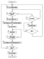
- the control unit 15 When receiving the picking information or the storage information from the upper controller, the control unit 15 starts the first traveling control (S1), and the target storage unit 1A (the plurality of target storage units 1A) specified by the picking information or the storage information.
- the traveling unit 11 arrives at the set position P1 corresponding to one of them (if one is designated), the first traveling control ends (S2, S3).
- the control unit 15 starts the display control and the first irradiation control in a state where the traveling unit 11 is located at the set position P1 (S4).
- the control unit 15 executes the reading control in accordance with the reading of the barcode of the article W by the barcode reader 17 (S5), and then completes the operation at one set position P1 by the detection control (the supporting unit). It is determined whether or not the article W has been correctly loaded and unloaded on the device 12 (S6, S7). When the work at one set position P1 is completed (S7: Yes), the display control and the first irradiation control are ended (S8). If the work has been completed for all of the plurality of target storage sections 1A specified by the picking information and storage information (S9: Yes), the second travel control is executed (S10).
- the following first travel control is started so that the travel section 11 travels to the set position P1 corresponding to the target storage section 1A for which the work has not been completed (S1).
- the control unit 15 continues the first traveling control. If the above-described event occurs during the execution and the traveling unit 11 abnormally stops (S11: Yes), the second irradiation control is executed (S12). Thereafter, the control unit 15 continues the second irradiation control (S12) until the traveling unit 11 recovers from the abnormal stop state (S13: No), and when the traveling unit 11 recovers from the abnormal stop state ( S13: Yes), the first traveling control is restarted (S1).
- the control unit 15 starts the first irradiation control as the execution of the first traveling control ends as described above, and determines that the operation at one set position P1 is completed by the detection control, and the second traveling Before executing the control, the first irradiation control is ended.
- the first irradiation control as shown in the flowchart of FIG. 8, first, light of a color corresponding to the storage type is continuously irradiated to a large range (S21).
- the identification information reading unit 19 reads the identification information by executing the reading control in a state where the light irradiation range is large (S22: No, S24: Yes)
- the worker M It is determined that the work is being performed, and the light irradiation range is changed from the large range to the small range (S25). If the set time has elapsed after the execution of the first traveling control is completed in a state where the light is continuously emitted (S23: No, S26: Yes), it is determined that the priority of the own vehicle is high. Then, the light irradiation interval is changed from the state of continuous irradiation to the state of intermittent irradiation (S27).
- the irradiation position P2 is set to the ceiling surface C, but the irradiation position P2 may be changed as appropriate.
- an irradiation target may be installed above a plurality of storage units 1 (article storage shelves 2), and an irradiation position P2 may be set for the irradiation target.
- the irradiation position P2 may be set on an installation object such as a beam installed in the picking facility.
- the work information, the priority information, the storage type information, and the abnormality information are displayed at the irradiation position P2, but the work information, the priority information, the storage type information, and the abnormality information are displayed at the irradiation position P2. It is good also as composition which displays only some of them. Further, information other than the work information, the priority information, the storage type information, and the abnormality information may be displayed at the irradiation position P2.
- the work information is displayed by the size of the light irradiation range at the irradiation position P2
- the priority information is displayed by the flashing interval of the light
- the storage type information is displayed by the color of the light
- the abnormality information is displayed.
- the display method of each information is not limited to this. That is, the configuration may be such that the work information is displayed in the blinking interval of the light, the color of the light, or the shape of the light, or the priority information may be displayed in the size of the irradiation range of the light, the color of the light, or the shape of the light.
- the storage type information may be displayed in the form of the size of the light irradiation range, the light blinking interval, and the light shape, or the abnormal information may be displayed as the light blinking interval, the size of the light irradiation range, the light shape, and the like. It may be configured to display one of the colors. Alternatively, such information may be displayed as a character string, a mark, or the like, may be displayed as light intensity (brightness), or may be displayed as to whether or not light has been irradiated. Further, a configuration may be adopted in which a plurality of various display methods described above are combined to display each information.
- the priority is determined based on the standby time of the vehicle at the current set position P1, but the priority determination condition may be changed as appropriate. Specifically, the priority may be determined so that the priority increases as the time until the shipping deadline of the article W supported by the support unit 12 decreases. In addition, the number of the set positions P1 at which the own vehicle is determined to be heading thereafter (the number of the target storage units 1A whose work has not been completed among the plurality of target storage units 1A specified by the picking information or the storage information). The priority may be determined so that the priority increases as the number increases. The priority may be determined so that the priority increases as the remaining charge of the battery 16 decreases.
- the priority may be determined based on a combination of two or more of the waiting time of the vehicle, the shipping deadline of the article W, the number of the set positions P1 heading thereafter, and the remaining charge of the battery 16. .
- the priority may be determined using conditions other than these.
- whether or not the worker M is working on the own vehicle is determined based on the identification information of the identification information reading unit 19; however, the worker M is working on the own vehicle.
- the information source for determining whether or not the information may be changed as appropriate. Specifically, based on the read information of the barcode reader 17 and the weighing information of the weighing unit 18, it may be determined whether or not the worker M is working on the own vehicle. In this case, based on whether the barcode reader 17 reads the barcode of the article W and whether the weight measured by the weighing unit 18 fluctuates in a state where the article transport vehicle 3 is at the set position P1. It is preferable to determine whether the worker M is working on the own vehicle.
- the irradiation unit 13 irradiates the light directly upward, but the irradiation unit 13 may irradiate the light obliquely upward.
- the storage unit 1 at the storage destination is also the target storage unit 1A, but only the storage unit 1 at the warehouse may be the target storage unit 1A.
- the irradiation control and the display control are started with the end of the traveling control.
- one or both of the irradiation control and the display control are started before the traveling control ends.
- the display control may be started at the same time as the start of the travel control or during the execution of the travel control, or the irradiation control may be started during the execution of the travel control.
- the irradiation unit 13 is controlled to execute the traveling control (the traveling unit 11 is traveling) or the traveling control is terminated (the traveling unit 11 stops at the set position P1).
- the irradiating unit 13 irradiates visible light, but the irradiating unit 13 may irradiate invisible light (ultraviolet light, infrared light, or the like).
- invisible light ultraviolet light, infrared light, or the like.
- a member including a phosphor that emits light by invisible light may be provided at the irradiation position P2, or a paint including the phosphor may be applied.
- the article transport vehicle includes a traveling unit that travels to a set position set corresponding to each of the plurality of storage units that store the articles, a support unit that supports the articles, an irradiation unit that emits light, and the traveling unit. And a control unit that controls the irradiation unit, wherein the storage unit in which the article to be supported by the support unit is stored is set as a target storage unit, and the control unit is set corresponding to the target storage unit. Traveling control for controlling the traveling unit so that the traveling unit travels to the set position, and corresponding to the own vehicle at a position above the plurality of storage units in a state where the traveling unit is at the set position. And irradiation control for controlling the irradiation unit so as to irradiate the irradiation position which is the position to be irradiated with light.
- the control unit executes the traveling control, so that the traveling unit travels to the set position, and the control unit executes the irradiation control, so that the irradiation unit emits light to the irradiation position.
- This irradiation position is a position above the plurality of storage units and a position corresponding to the own vehicle, so that even an operator who is away from the article transport vehicle or a worker who is in a place separated by the storage unit, etc. It is possible to recognize that the article transport vehicle that needs to perform the picking operation is at the set position. For this reason, the worker can easily recognize that it is necessary to perform the picking operation on the article transport vehicle, and can easily perform the picking operation.
- the irradiation unit is configured to be able to irradiate the irradiation position with work information that is information indicating whether or not the worker is working on the own vehicle, and the control unit is configured so that the worker
- the irradiation unit is controlled so that the work information is displayed at the irradiation position depending on whether or not the work is being performed.
- the control unit executes the irradiation control, whereby the work information is displayed at the irradiation position. For this reason, the worker who is not working on the article transport vehicle that is irradiating the irradiation position with light, confirms the light that has been irradiated on the irradiation position, and then checks the article transport vehicle that is irradiating the light with the light. On the other hand, it can be determined whether or not another worker is working. Therefore, even when the worker is away from the article transport vehicle, it is possible to determine whether or not the worker himself / herself needs to perform an operation on the article transport vehicle, thereby facilitating the picking operation.
- the control information includes an identification information reading unit that reads the identification information of the worker held in the identification information holding body of the worker, Preferably, the unit determines whether or not the worker is working on the own vehicle based on the detection information of the identification information reading unit.
- the irradiating unit is configured to be able to irradiate the irradiating position with priority information that is information indicating a priority of the own vehicle, and the control unit is configured to determine a priority determined based on a predetermined priority determining condition.
- the irradiation unit is controlled so as to display the priority information at the irradiation position according to the degree.
- the worker can recognize the priority of the work on the article transport vehicle corresponding to the light by confirming the light irradiated to the irradiation position. For this reason, it is possible for the operator to preferentially perform the work on the article transport vehicle with a high priority. Thus, it is possible to avoid delaying the work on the article transport vehicle with high priority, and to facilitate the picking work.
- the priority determination condition is a shipping deadline of an article to be supported by the support portion, a waiting time of the own vehicle at the current set position, the number of the set positions where the own vehicle is determined to be headed thereafter, And, when a battery that supplies driving power to at least one of the traveling unit, the irradiation unit, and the control unit is provided, based on at least one of the remaining charge amount of the battery. It is preferable that the condition is such that the priority is determined to be higher in descending order of necessity of urgently performing the work of the worker at the current set position.
- an article transport vehicle that transports an article whose expiration date is approaching, an article transport vehicle that has a long waiting time at the current set position, an article transport vehicle that has a large number of set positions heading thereafter, and a battery
- An article transport vehicle with a small remaining charge can be a high priority article transport vehicle. Therefore, it is possible for the operator to give priority to the work on these article transport vehicles.
- the storage unit at the storage destination storing the articles supported by the support unit is preferably the target storage unit. It is.
- the irradiation section may be configured such that the target storage section is the storage section at the delivery source or the storage section at the storage destination.
- the storage unit is configured to be capable of irradiating light so as to display the storage type information indicating the unit at the irradiation position.
- the control unit may be configured such that the target storage unit is the storage unit of the delivery source or the storage destination.
- the irradiation unit is controlled so that the storage type information corresponding to the storage unit is displayed at the irradiation position.
- the work performed on the target storage unit is performed by taking out the object from the target storage unit or storing the object in the target storage unit. Can be recognized in advance by the operator. Therefore, even when there is a possibility that both the work of taking out the article from the target storage section and the work of storing the article in the target storage section, these works can be facilitated.
- the irradiation position is set on a ceiling surface directly above the own vehicle.
- the configuration of the irradiation unit can be simplified and the control of the irradiation unit in the irradiation control can be simplified.
- the light from the irradiating section is irradiated on the ceiling surface, it is easy for an operator to visually recognize the light.
- the irradiation unit is configured to be able to irradiate the irradiation position with abnormality information indicating that an abnormality has occurred in the own vehicle, and the control unit is configured to execute the traveling unit at a position other than the set position during the traveling control. When is stopped, it is preferable to execute second irradiation control for controlling the irradiation unit so as to display the abnormality information at the irradiation position.
- the worker can recognize that the article transport vehicle has abnormally stopped at a position other than the set position by checking the light irradiated to the irradiation position. Therefore, the operator can quickly find the article transport vehicle in which the abnormality has occurred. As a result, the article transport vehicle in which the abnormality has occurred can be quickly restored.
- the technology according to the present disclosure can be used for an article transport vehicle provided with a support section that supports an article.
- storage section 1A target storage section 10: identification information holding body 11: traveling section 12: support section 13: irradiation section 15: control section 16: battery 19: identification information reading section C: ceiling surface M: worker P1: Set position P2: Irradiation position W: Article
Landscapes
- Engineering & Computer Science (AREA)
- Mechanical Engineering (AREA)
- Physics & Mathematics (AREA)
- General Physics & Mathematics (AREA)
- Theoretical Computer Science (AREA)
- Electromagnetism (AREA)
- Health & Medical Sciences (AREA)
- General Health & Medical Sciences (AREA)
- Toxicology (AREA)
- Artificial Intelligence (AREA)
- Computer Vision & Pattern Recognition (AREA)
- Warehouses Or Storage Devices (AREA)
Abstract
This article transport vehicle (3) comprises: a travel portion (11) that travels to a preset position (P1) which is set so as to correspond to each of a plurality of containers (1) in which articles are stored; a support portion (12) that supports the articles; an irradiation unit (13) that radiates light; and a control unit that controls the travel portion (11) and the irradiation unit (13). Using the container (1) in which the articles to be supported by the support portion (12) are stored, as a target container (1A), the control unit performs travel control for causing the travel portion (11) to travel to the preset position (P1) set corresponding to the target container (1A) and irradiation control for controlling the irradiation unit (13) to irradiate with light an irradiation position (P2), which is a position above the plurality of containers (1) and corresponding to the vehicle, in a state in which the travel portion (11) is located at the preset position (P1).
Description
本発明は、物品を支持する支持部を備えた物品搬送車に関する。
The present invention relates to an article transport vehicle provided with a support for supporting an article.
以下、背景技術について説明する。以下の説明において、かっこ書きの符号又は名称は、先行技術文献における符号又は名称とする。かかる物品搬送車の一例が、特開2008-247546号公報(特許文献1)に記載されている。特許文献1の物品搬送車(ピッキング作業用台車)は、ピッキング設備に備えられている。このピッキング設備では、物品搬送車を作業者の押し引き操作により移動させて、目的の収納棚(3)の収納部(物品収納部5)の近くまで移動させ、収納棚の収納部から物品を取り出して物品搬送車の支持部(コンテナ8)に支持させるピッキング作業が行われる。
背景 The background art will be described below. In the following description, the signs or names in parentheses are the signs or names in the prior art document. An example of such an article transport vehicle is described in Japanese Patent Application Laid-Open No. 2008-247546 (Patent Document 1). The article transport vehicle (picking work cart) of Patent Document 1 is provided in a picking facility. In this picking facility, the article transport vehicle is moved by a push-pull operation of an operator to move the article transport vehicle near the storage section (article storage section 5) of the target storage shelf (3), and articles are moved from the storage section of the storage shelf. A picking operation is performed in which the picked-up article is taken out and supported by the support section (container 8) of the article transport vehicle.
作業者の作業量を抑えるために、物品搬送車を、目的の収納棚の収納部の近くの設定位置まで自動的に走行するように構成し、作業者は、設定位置に停止している物品搬送車に対してピッキング作業を行うようにすることが考えられる。しかし、このように物品搬送車を自動的に走行するように構成すると、物品搬送車が作業者から見えない位置又は見えにくい位置に停止している場合に、作業者が物品搬送車に対してピッキング作業を行う必要があることに気付き難く、ピッキング作業を円滑に行えない場合が考えられる。
In order to reduce the amount of work of the worker, the article carrier is configured to automatically travel to a set position near the storage section of the target storage shelf, and the worker stops the article stopped at the set position. It is conceivable to perform a picking operation on the transport vehicle. However, when the article transport vehicle is configured to run automatically in this way, when the article transport vehicle is stopped at a position that is invisible or difficult to be seen by the worker, the worker moves the article transport vehicle relative to the article transport vehicle. It may be difficult to notice that it is necessary to perform the picking operation, and the picking operation may not be performed smoothly.
そこで、ピッキング作業を円滑に行い易い物品搬送車の実現が望まれる。
Therefore, it is desired to realize an article transport vehicle that facilitates the picking operation.
本開示に係る物品搬送車は、物品を収納する複数の収納部の夫々に対応して設定された設定位置まで走行する走行部と、物品を支持する支持部と、光を照射する照射部と、前記走行部及び前記照射部を制御する制御部と、を備え、前記支持部に支持させる物品が収納されている前記収納部を対象収納部として、前記制御部は、前記対象収納部に対応して設定された前記設定位置まで前記走行部を走行させるように前記走行部を制御する走行制御と、前記走行部が前記設定位置にある状態で、複数の前記収納部より上方の位置で且つ自車に対応する位置である照射位置に光を照射するように前記照射部を制御する照射制御と、を実行する。
The article transport vehicle according to the present disclosure is a traveling unit that travels to a set position set corresponding to each of a plurality of storage units that store articles, a support unit that supports the articles, and an irradiation unit that emits light. A control unit that controls the traveling unit and the irradiation unit, wherein the storage unit in which an article to be supported by the support unit is stored is a target storage unit, and the control unit corresponds to the target storage unit. Traveling control for controlling the traveling section so that the traveling section travels to the set position set as above, and in a state where the traveling section is at the set position, at a position above a plurality of the storage sections, and And irradiating control for controlling the irradiating unit so as to irradiate light to an irradiating position corresponding to the own vehicle.
この構成によれば、制御部が走行制御を実行することで、走行部が設定位置まで走行し、制御部が照射制御を実行することで、照射部が照射位置に光を照射する。この照射位置は、複数の収納部より上方の位置で且つ自車に対応する位置であるため、物品搬送車から離れている作業者や収納部によって隔てられた場所にいる作業者等にも、ピッキング作業を行う必要がある物品搬送車が設定位置にあることを認識することができる。このため、作業者が物品搬送車に対してピッキング作業を行う必要があることに気付き易くでき、ピッキング作業を円滑に行い易くすることができる。
According to this configuration, the control unit executes the traveling control, so that the traveling unit travels to the set position, and the control unit executes the irradiation control, so that the irradiation unit emits light to the irradiation position. This irradiation position is a position above the plurality of storage units and a position corresponding to the own vehicle, so that even an operator who is away from the article transport vehicle or a worker who is in a place separated by the storage unit, etc. It is possible to recognize that the article transport vehicle that needs to perform the picking operation is at the set position. For this reason, the worker can easily recognize that it is necessary to perform the picking operation on the article transport vehicle, and can easily perform the picking operation.
1.実施形態
ピッキング設備に用いられる物品搬送車の実施形態について図面に基づいて説明する。
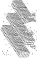
図1及び図2に示すように、ピッキング設備には、物品Wを収納する収納部1を複数備えた物品収納棚2と、床面F上を走行する物品搬送車3と、物品収納棚2に収納されている物品Wを管理し且つ物品搬送車3を制御する制御装置H(図6参照)と、が備えられている。 1. Embodiment An embodiment of an article carrier used in a picking facility will be described with reference to the drawings.
As shown in FIGS. 1 and 2, the picking equipment includes anarticle storage shelf 2 having a plurality of storage sections 1 for storing articles W, an article transport vehicle 3 running on a floor F, and an article storage shelf 2. And a control device H (see FIG. 6) that manages the articles W stored in the vehicle and controls the article transport vehicle 3.
ピッキング設備に用いられる物品搬送車の実施形態について図面に基づいて説明する。
図1及び図2に示すように、ピッキング設備には、物品Wを収納する収納部1を複数備えた物品収納棚2と、床面F上を走行する物品搬送車3と、物品収納棚2に収納されている物品Wを管理し且つ物品搬送車3を制御する制御装置H(図6参照)と、が備えられている。 1. Embodiment An embodiment of an article carrier used in a picking facility will be described with reference to the drawings.
As shown in FIGS. 1 and 2, the picking equipment includes an
以下、物品収納棚2や物品搬送車3について説明するが、上下方向Zに見た上下方向Z視において、物品収納棚2の収納部1が並ぶ方向を第1方向Xと称し、第1方向Xに対して直交する方向を第2方向Yと称する。そして、図4に示すように、第1方向Xの一方側を第1方向第1側X1と称し、その反対側を第1方向第2側X2と称する。また、第2方向Yにおいて、作業通路Lの中央に対して収納部1が存在する側を収納部側Y2と称し、その反対側(収納部1に対して作業通路Lが存在する側)を通路側Y1と称する。物品搬送車3については、物品搬送車3が直進する場合の進行方向に沿った方向を前後方向Uと称し、水平面において前後方向Uに対して直交する方向を幅方向Vと称する。そして、前後方向Uにおける物品搬送車3の進行方向側を前方側U1と称し、その反対側を後方側U2と称する。
Hereinafter, the article storage shelves 2 and the article transport vehicle 3 will be described. In the vertical direction Z when viewed in the vertical direction Z, the direction in which the storage units 1 of the article storage shelves 2 are arranged is referred to as a first direction X, and the first direction X. A direction orthogonal to X is referred to as a second direction Y. Then, as shown in FIG. 4, one side in the first direction X is referred to as a first direction first side X1, and the opposite side is referred to as a first direction second side X2. In the second direction Y, the side where the storage section 1 exists with respect to the center of the work path L is referred to as the storage section side Y2, and the opposite side (the side where the work path L exists with respect to the storage section 1). It is referred to as the passage side Y1. Regarding the article transport vehicle 3, a direction along the traveling direction when the article transport vehicle 3 goes straight ahead is referred to as a front-rear direction U, and a direction orthogonal to the front-rear direction U on a horizontal plane is referred to as a width direction V. Then, the traveling direction side of the article transport vehicle 3 in the front-rear direction U is referred to as a front side U1, and the opposite side is referred to as a rear side U2.
物品収納棚2は、上下方向Z及び第1方向Xに並ぶ状態で複数の収納部1を備えている。説明を加えると、物品収納棚2は、上下方向Zに間隔を隔てた状態で複数の棚板6を備えており、複数の棚板6上に、第1方向Xに並ぶ状態で複数の収納用容器7が載せられている。このように物品収納棚2に備えられている複数の収納用容器7のそれぞれにより収納部1が形成されている。収納用容器7(収納部1)には、複数種類の物品Wが種類別に収納されており、1つの収納用容器7には1種類の物品Wが収容されている。
The article storage shelf 2 includes a plurality of storage units 1 arranged in the vertical direction Z and the first direction X. In addition, the article storage shelf 2 includes a plurality of shelves 6 spaced apart in the vertical direction Z, and a plurality of storage shelves on the plurality of shelves 6 arranged in the first direction X. Container 7 is placed. As described above, the storage section 1 is formed by each of the plurality of storage containers 7 provided in the article storage shelf 2. The storage container 7 (storage section 1) stores a plurality of types of articles W by type, and one storage container 7 stores one type of article W.
収納用容器7は、物品Wを出し入れする開口部8を有する開口面9を備えている。収納用容器7は、開口面9が通路側Y1を向くように物品収納棚2に設置されている。そのため、この収納用容器7により形成されている収納部1のそれぞれは、物品Wを出し入れする開口部8を有する開口面9を備えている。そして、1つの物品収納棚2に備えられている複数の収納部1は、開口面9を同じ方向に向けて配列されている。
The storage container 7 has an opening surface 9 having an opening 8 into and out of the article W. The storage container 7 is installed on the article storage shelf 2 such that the opening surface 9 faces the passage side Y1. Therefore, each of the storage sections 1 formed by the storage containers 7 has an opening surface 9 having an opening 8 through which articles W are put in and out. The plurality of storage sections 1 provided in one article storage shelf 2 are arranged with the opening surfaces 9 facing in the same direction.
図1に示すように、物品収納棚2が設置されている領域は、複数のエリアEに区分けされている。そして、本実施形態では、その複数のエリアEの夫々に対して担当の作業者Mが配置されている。作業者Mは、自身が担当するエリアEにおいて、物品収納棚2から物品搬送車3に物品Wを移載するピッキング作業や、物品搬送車3から物品収納棚2に物品Wを移載する収納作業を行う。なお、エリアEの数と作業者Mの数との関係は任意に変更可能であり、例えば、1つのエリアEに複数人の作業者Mが配置されていてもよいし、複数のエリアEを1人の作業者Mが担当するようにしてもよい。作業者Mは、識別情報保持体10を有している。識別情報保持体10は、当該識別情報保持体10を有する作業者Mの識別情報を保持している。本実施形態では、識別情報保持体10を、RFIDタグを有する保持体(例えばIDカード等)としており、RFIDタグに作業者Mの識別情報が記憶されている。
領域 As shown in FIG. 1, the area where the article storage shelves 2 are installed is divided into a plurality of areas E. In the present embodiment, a worker M is assigned to each of the plurality of areas E. The worker M picks up the article W from the article storage shelf 2 to the article transport vehicle 3 in the area E in which the worker M is in charge, and stores the article W from the article transport vehicle 3 to the article storage shelf 2. Do the work. Note that the relationship between the number of areas E and the number of workers M can be arbitrarily changed. For example, a plurality of workers M may be arranged in one area E, One worker M may be in charge. The worker M has an identification information holding body 10. The identification information holder 10 holds identification information of the worker M having the identification information holder 10. In the present embodiment, the identification information holder 10 is a holder (for example, an ID card) having an RFID tag, and the identification information of the worker M is stored in the RFID tag.
図6に示す制御装置Hは、収納部1に収納されている物品Wの個数や収納部1に収納されている物品Wの種類の情報である収納物品情報を記憶している。
制御装置Hは、上位のコントローラからピッキング指令が出力されると、ピッキング指令と収納物品情報とに基づいて、ピッキング情報を物品搬送車3の制御部15に送信するように構成されている。ピッキング情報は、ピッキング作業により物品Wを取り出す収納部1(対象収納部1A)の位置を示す情報や収納部1から取り出す物品Wの種類や個数の情報である。また、制御装置Hは、上位のコントローラから収納指令が出力されると、収納指令と収納物品情報とに基づいて、収納情報を物品搬送車3の制御部15に送信するように構成されている。収納情報は、収納作業により物品Wを収納する収納部1(対象収納部1A)の位置を示す情報や収納部1に収納する物品Wの種類や個数の情報である。 The control device H illustrated in FIG. 6 stores stored article information that is information on the number of articles W stored in thestorage section 1 and the types of the articles W stored in the storage section 1.
The control device H is configured to, when a picking command is output from a higher-order controller, transmit the picking information to thecontrol unit 15 of the article transport vehicle 3 based on the picking command and the stored article information. The picking information is information indicating the position of the storage unit 1 (target storage unit 1A) from which the articles W are taken out by the picking operation, and information on the type and number of the articles W to be taken out from the storage unit 1. In addition, the control device H is configured to, when a storage command is output from a higher-level controller, transmit storage information to the control unit 15 of the article transport vehicle 3 based on the storage command and the stored article information. . The storage information is information indicating the position of the storage unit 1 (target storage unit 1A) that stores the articles W by the storage operation, and information on the type and number of the articles W stored in the storage unit 1.
制御装置Hは、上位のコントローラからピッキング指令が出力されると、ピッキング指令と収納物品情報とに基づいて、ピッキング情報を物品搬送車3の制御部15に送信するように構成されている。ピッキング情報は、ピッキング作業により物品Wを取り出す収納部1(対象収納部1A)の位置を示す情報や収納部1から取り出す物品Wの種類や個数の情報である。また、制御装置Hは、上位のコントローラから収納指令が出力されると、収納指令と収納物品情報とに基づいて、収納情報を物品搬送車3の制御部15に送信するように構成されている。収納情報は、収納作業により物品Wを収納する収納部1(対象収納部1A)の位置を示す情報や収納部1に収納する物品Wの種類や個数の情報である。 The control device H illustrated in FIG. 6 stores stored article information that is information on the number of articles W stored in the
The control device H is configured to, when a picking command is output from a higher-order controller, transmit the picking information to the
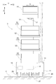
図3に示すように、物品搬送車3は、床面F上を走行する走行部11と、物品Wを支持する支持部12と、光を照射する照射部13と、ピッキング情報や収納情報を表示する表示部14と、走行部11、照射部13、及び表示部14を制御する制御部15と、を備えている。また、図6に示すように、物品搬送車3は、バッテリ16(図3参照)と、物品Wに表示されているバーコードを読み取るバーコードリーダ17と、支持部12が支持している物品Wの重量を計測する秤量部18と、作業者Mの識別情報を読み取る識別情報読み取り部19と、を備えている。バッテリ16は、走行部11、照射部13、表示部14、バーコードリーダ17、秤量部18、及び識別情報読み取り部19に駆動用電力を供給する。
As shown in FIG. 3, the article transport vehicle 3 includes a traveling unit 11 that travels on the floor F, a support unit 12 that supports the article W, an irradiation unit 13 that irradiates light, and picking information and storage information. The display unit 14 includes a display unit 14 for displaying, and a control unit 15 that controls the traveling unit 11, the irradiation unit 13, and the display unit 14. As shown in FIG. 6, the article transport vehicle 3 includes a battery 16 (see FIG. 3), a bar code reader 17 that reads a bar code displayed on the article W, and an article supported by the support unit 12. A weighing unit 18 for measuring the weight of W and an identification information reading unit 19 for reading identification information of the worker M are provided. The battery 16 supplies driving power to the traveling unit 11, the irradiation unit 13, the display unit 14, the barcode reader 17, the weighing unit 18, and the identification information reading unit 19.
走行部11は、第2方向Yに並ぶ一対の走行輪26と、この一対の走行輪26に対して第1方向Xの両側に設置された従動輪27と、走行輪26を回転駆動させる走行用モータ28(図6参照)と、を備えている。走行用モータ28は、バッテリ16から供給される駆動用電力により駆動される。走行部11は、走行用モータ28によって一対の走行輪26の双方を正転方向に回転させることで前進走行し、走行用モータ28によって一対の走行輪26の双方を逆転方向に回転させることで後進走行する。また、走行部11は、走行用モータ28によって一対の走行輪26を異なる回転速度で回転させることで旋回走行する。なお、ここでは、図4に示すように、物品搬送車3の前後方向Uが第1方向Xに沿う向きで物品搬送車3が停止している状態に基づいて、方向を定義している。図4に示す状態では、物品搬送車3の前方側U1が第1方向第2側X2を向き、物品搬送車3の後方側U2が第1方向第1側X1を向き、物品搬送車3の右側が収納部側Y2を向き、物品搬送車3の左側が通路側Y1を向いている。
The traveling unit 11 includes a pair of traveling wheels 26 arranged in the second direction Y, a driven wheel 27 installed on both sides in the first direction X with respect to the pair of traveling wheels 26, and a traveling that rotationally drives the traveling wheels 26. Motor 28 (see FIG. 6). The traveling motor 28 is driven by driving power supplied from the battery 16. The traveling unit 11 travels forward by rotating both of the pair of traveling wheels 26 in the normal rotation direction by the traveling motor 28, and rotates both of the pair of traveling wheels 26 in the reverse rotation direction by the traveling motor 28. Drive backward. In addition, the traveling unit 11 performs turning traveling by rotating the pair of traveling wheels 26 at different rotational speeds by the traveling motor 28. Here, as shown in FIG. 4, the direction is defined based on the state in which the article transport vehicle 3 is stopped with the front-rear direction U of the article transport vehicle 3 along the first direction X. In the state shown in FIG. 4, the front side U1 of the article transport vehicle 3 faces the second direction X2 in the first direction, the rear side U2 of the article transport vehicle 3 faces the first direction X1 in the first direction. The right side faces the storage unit side Y2, and the left side of the article transport vehicle 3 faces the passage side Y1.
走行部11には、支柱31が立設されている。図示の例では、この支柱31の上下方向Zの中間位置に2つの支持台32が上下方向Zに並ぶ状態で支持されている。また、支柱31の上端に表示部14が支持されている。走行部11及び2つの支持台32の夫々に搬送用容器33が支持されており、これらの搬送用容器33が、物品Wを支持する支持部12に相当する。
支 The support 31 is provided upright on the traveling section 11. In the illustrated example, two support bases 32 are supported at a middle position of the support column 31 in the vertical direction Z in a state of being aligned in the vertical direction Z. The display unit 14 is supported on the upper end of the column 31. A transport container 33 is supported by each of the traveling unit 11 and the two support stands 32, and these transport containers 33 correspond to the support unit 12 that supports the article W.
表示部14は、ピッキング情報や収納情報を表示可能に構成されている。表示部14は、タッチパネルを有しており、作業者Mが操作可能に構成されている。図4に示すように、物品搬送車3の前方側U1が第1方向第2側X2を向くように物品搬送車3が停止している状態において、表示部14は、各種情報を表示する表示画面が第1方向第1側X1で且つ上方側を向くように設置されている。
The display unit 14 is configured to display picking information and storage information. The display unit 14 has a touch panel, and is configured to be operable by the worker M. As shown in FIG. 4, in a state where the article transport vehicle 3 is stopped such that the front side U1 of the article transport vehicle 3 faces the second direction X2 in the first direction, the display unit 14 displays various information. The screen is installed so as to face the first side in the first direction X1 and upward.
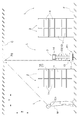
照射部13は、走行部11が設定位置P1にある状態で、物品収納棚2(複数の収納部1)より上方の位置で且つ自車に対応する位置である照射位置P2に光を照射する。説明を加えると、図5に示すように、設定位置P1は作業通路Lに設定されており、作業通路Lの上方には、ピッキング設備が設置された施設の天井がある。そのため、走行部11が設定位置P1にある状態では、照射部13から真上に向けて照射された光は、当該天井における下方を向く天井面Cに照射される。そして、このように走行部11が設定位置P1にある状態で照射部13により照射された位置が照射位置P2に相当する、つまり、照射位置P2は、自車の真上の天井面Cに設定されている。本実施形態では、照射部13は、作業者Mが肉眼で感じることのできる可視光を照射する。また、本実施形態では、照射位置P2は、この照射位置P2の真下の作業通路Lとは別の作業通路Lで作業を行っている作業者Mが目視可能となっている。
The irradiation unit 13 irradiates light to an irradiation position P2 which is a position above the article storage shelf 2 (the plurality of storage units 1) and a position corresponding to the own vehicle in a state where the traveling unit 11 is at the set position P1. . In addition, as shown in FIG. 5, the setting position P1 is set in the work passage L, and above the work passage L is the ceiling of the facility where the picking facilities are installed. Therefore, in a state where the traveling unit 11 is at the set position P1, the light emitted from the irradiation unit 13 directly upward is applied to the ceiling surface C of the ceiling facing downward. The position irradiated by the irradiation unit 13 in the state where the traveling unit 11 is at the set position P1 corresponds to the irradiation position P2, that is, the irradiation position P2 is set on the ceiling surface C directly above the own vehicle. Have been. In the present embodiment, the irradiating unit 13 irradiates visible light that the worker M can feel with the naked eye. Further, in the present embodiment, the irradiation position P2 is visible to a worker M who is working in a work path L different from the work path L immediately below the irradiation position P2.
照射部13は、作業者Mが自車に対して作業中であるか否かを示す情報である作業情報と、自車の優先度を示す情報である優先情報と、対象収納部1Aが出庫元の収納部1(ピッキング作業において物品Wを取り出す収納部1)か入庫先の収納部1(収納作業において物品Wを収納する収納部1)かを示す収納種別情報と、自車に異常が生じたことを示す異常情報と、を照射位置P2に照射可能に構成されている。本実施形態では、照射部13は、照射する光の色で収納種別情報を表示する。具体的には、照射部13は、複数色の光を照射可能に構成されており、対象収納部1Aが出庫元の収納部1である場合と対象収納部1Aが入庫先の収納部1である場合とで、照射位置P2に照射する光の色を異ならせるように構成されている。
The irradiating unit 13 includes work information that is information indicating whether the worker M is working on the own vehicle, priority information that is information indicating the priority of the own vehicle, and that the target storage unit 1A is out of stock. Storage type information indicating whether the original storage unit 1 (storage unit 1 for taking out the article W in the picking operation) or the storage unit 1 at the storage destination (the storage unit 1 for storing the article W in the storage operation), and an abnormality in the own vehicle. Irradiation position P2 and abnormality information indicating that the abnormality has occurred can be applied to the irradiation position P2. In the present embodiment, the irradiation unit 13 displays the storage type information in the color of the light to be irradiated. More specifically, the irradiation unit 13 is configured to be capable of irradiating light of a plurality of colors. It is configured such that the color of the light irradiated to the irradiation position P2 is different between a certain case.
また、照射部13は、光を照射する範囲の大きさで作業者Mが自車に対して作業中か否かを示す作業情報を表示する。本例では、照射部13は、作業者Mが自車に対して作業中でない場合は、作業者Mが自車に対して作業中である場合に比べて、広い範囲を照射するように構成されている。本実施形態では、作業者Mが自車に対して作業中でない場合は、半径が第1長さの円形で形成された範囲(以下、大範囲と称する)を照射し、作業者Mが自車に対して作業中である場合は、半径が第1長さより短い第2長さの円形で形成された範囲(以下、小範囲と称する)を照射する。
(4) The irradiation unit 13 displays work information indicating whether or not the worker M is working on the own vehicle with a size of a light irradiation range. In the present example, the irradiation unit 13 is configured to irradiate a wider range when the worker M is not working on the own vehicle than when the worker M is working on the own vehicle. Have been. In the present embodiment, when the worker M is not working on the own vehicle, the worker irradiates a range (hereinafter, referred to as a large range) having a radius of a first length and is formed by a circle. When the vehicle is being worked on, a range formed by a circle having a second length whose radius is shorter than the first length (hereinafter, referred to as a small range) is irradiated.
また、照射部13は、照射する光の点滅間隔で優先度を示す優先情報を表示するように構成されている。例えば、光の点滅間隔が短くなるに従って優先度が高いことを示すように構成することができる。ここで、優先度が2段階である場合には、光を連続的に照射することで優先度が低いことを示し、光を断続的に照射(点滅)させることで優先度が高いことを示すように構成することができる。本実施形態では、一例として、優先度を2段階で判定する構成を例として説明する。
The irradiation unit 13 is configured to display priority information indicating the priority at the blinking interval of the light to be irradiated. For example, it can be configured to indicate that the priority is higher as the light blinking interval becomes shorter. Here, when the priority has two levels, it indicates that the priority is low by continuously irradiating the light, and indicates that the priority is high by irradiating (flashing) the light intermittently. It can be configured as follows. In the present embodiment, a configuration in which the priority is determined in two stages will be described as an example.
また、照射部13は、照射する光の形状で自車に異常が生じたことを示す異常情報を表示するように構成されている。本例では、上述した作業情報や優先情報や収納種別情報とは異なる形状及び色の光を照射する。具体的には、照射部13は、上述した作業情報や優先情報や収納種別情報を示す場合には、円形で形成された範囲を照射するのに対して、異常情報を示す場合には、矩形で形成された範囲を照射する。更に本例では、照射部13は、収納種別情報を示す場合に使用する色とは異なる色(例えば赤色)の光を照射することでも異常情報であることを示す。
The irradiation unit 13 is configured to display abnormality information indicating that an abnormality has occurred in the vehicle in the shape of light to be irradiated. In this example, light of a shape and color different from the above-described work information, priority information, and storage type information is emitted. Specifically, the irradiating unit 13 irradiates the area formed in a circle when the work information, the priority information, and the storage type information are described above, whereas the irradiating unit 13 has a rectangular shape when indicating the abnormal information. The area formed by is irradiated. Further, in the present example, the irradiation unit 13 also indicates that the abnormality information is obtained by irradiating light of a color (for example, red) different from the color used when indicating the storage type information.
識別情報読み取り部19は、作業者Mが有する識別情報保持体10に保持されている作業者Mの識別情報を読み取り可能に構成されている。本実施形態では、識別情報読み取り部19は、識別情報保持体10との間で情報を無線通信可能に構成されている。具体的には、識別情報読み取り部19は、RFIDタグに記憶されている識別情報を読み取るリーダにより構成されている。そして、識別情報読み取り部19は、作業者Mが物品Wを支持部12に支持させる前にバーコードリーダ17に物品Wのバーコードを読み取らせる場合に、その作業者Mが存在すると想定される範囲が通信範囲となるように設定されている。つまり、作業者Mがバーコードリーダ17に物品Wのバーコードを読み取らせた場合に、その作業者Mが所持する識別情報保持体10の識別情報は読み取るが、自車から離れている作業者Mが所持する識別情報保持体10の識別情報は読み取らないように、通信範囲が設定されている。このような通信範囲の半径である通信距離は、例えば1mに設定されている。このように、識別情報読み取り部19は、予め設定された通信距離より近くに存在する識別情報保持体10の識別情報を読み取るように構成されている。
The identification information reading unit 19 is configured to be able to read the identification information of the worker M held in the identification information holding body 10 of the worker M. In the present embodiment, the identification information reading unit 19 is configured to be able to wirelessly communicate information with the identification information holder 10. Specifically, the identification information reading unit 19 is configured by a reader that reads the identification information stored in the RFID tag. When the operator M causes the barcode reader 17 to read the barcode of the article W before the worker M supports the article W on the support section 12, it is assumed that the worker M exists. The range is set to be the communication range. That is, when the worker M causes the barcode reader 17 to read the barcode of the article W, the worker reads the identification information of the identification information holding body 10 possessed by the worker M, but the worker who is away from the own vehicle. The communication range is set so that the identification information of the identification information holding body 10 possessed by M is not read. The communication distance, which is the radius of such a communication range, is set to, for example, 1 m. As described above, the identification information reading unit 19 is configured to read the identification information of the identification information holder 10 existing closer than the communication distance set in advance.
制御部15は、制御装置Hから送信されたピッキング情報や収納情報に基づいて、走行部11を制御する第1走行制御(走行制御に相当)及び第2走行制御、表示部14を制御する表示制御、走行部11が設定位置P1にある状態で照射位置P2に光を照射するように照射部13を制御する第1照射制御(照射制御に相当)、第1走行制御中に設定位置P1以外の位置で走行部11が停止した場合に、照射位置P2に異常情報を表示するように照射部13を制御する第2照射制御、識別情報読み取り部19により作業者Mの識別情報を読み取る読み取り制御、並びに、作業が完了したことを検出する検出制御、を実行する。
The control unit 15 performs a first traveling control (corresponding to traveling control) for controlling the traveling unit 11 and a second traveling control based on the picking information and the storage information transmitted from the control device H, and a display for controlling the display unit 14. Control, a first irradiation control (corresponding to irradiation control) for controlling the irradiation unit 13 so as to irradiate the irradiation position P2 with light in a state where the traveling unit 11 is at the set position P1, and other than the set position P1 during the first traveling control The second irradiation control that controls the irradiation unit 13 so that the abnormality information is displayed at the irradiation position P2 when the traveling unit 11 stops at the position indicated by, and the reading control that reads the identification information of the worker M by the identification information reading unit 19. , And detection control for detecting that the work is completed.
第1走行制御は、対象収納部1Aに対応して設定された設定位置P1まで走行部11を走行させるように走行部11を制御する。設定位置P1は、対象収納部1Aに対して通路側Y1であって、第1方向Xにおける第1方向第1側X1又は第1方向第2側X2に設定されている。図4に示す例では、対象収納部1Aに対して通路側Y1であって第1方向第2側X2に設定された設定位置P1に物品搬送車3が停止している。第2走行制御は、作業位置(図示せず)まで走行部11を走行させるように走行部11を制御する制御である。作業位置は、ピッキング作業により支持部12に支持された物品Wを物品搬送車3から降ろす作業や、収納作業により収納部1に収納する物品Wを支持部12に支持させる作業を行う箇所に対応して設定されている。制御部15は、第1走行制御の実行中に、バッテリ16の残量が設定値以下になった場合は、第1走行制御を中断して走行部11を停止させる。尚、第2走行制御の実行中に、バッテリ16の残量が設定値以下になった場合にも、第2走行制御を中断して走行部11を停止させるようにしてもよい。また、制御部15は、障害物の存在や、走行部11の故障等によって走行部11が正常な走行を継続できない事象が発生した場合にも、第1走行制御又は第2走行制御を中断して走行部11を停止させる。
The first traveling control controls the traveling unit 11 to travel to the set position P1 set corresponding to the target storage unit 1A. The set position P1 is on the passage side Y1 with respect to the target storage section 1A, and is set to the first direction first side X1 or the first direction second side X2 in the first direction X. In the example illustrated in FIG. 4, the article transport vehicle 3 is stopped at a set position P1 that is set on the passage side Y1 with respect to the target storage unit 1A and on the second side X2 in the first direction. The second traveling control is control for controlling the traveling unit 11 so that the traveling unit 11 travels to a work position (not shown). The work position corresponds to a place where an operation of lowering the article W supported by the support unit 12 by the picking operation from the article transport vehicle 3 and an operation of supporting the article W stored in the storage unit 1 by the support unit 12 by the storage operation. Is set. When the remaining amount of the battery 16 becomes equal to or less than the set value during the execution of the first traveling control, the control unit 15 interrupts the first traveling control and stops the traveling unit 11. Note that, even when the remaining amount of the battery 16 becomes equal to or less than the set value during the execution of the second traveling control, the second traveling control may be interrupted to stop the traveling unit 11. The control unit 15 also interrupts the first traveling control or the second traveling control when an event that the traveling unit 11 cannot continue normal traveling due to the presence of an obstacle or a failure of the traveling unit 11 occurs. To stop the traveling unit 11.
表示制御は、対象収納部1Aに対して出し入れする物品Wの数を示す数情報と、対象収納部1Aに対して出し入れする物品Wの種類を示す種類情報と、対象収納部1Aの位置を示す位置情報と、収納種別情報と、複数の搬送用容器33のうちの物品Wを出し入れする容器を示す容器情報と、を表示部14に表示させるように表示部14を制御する。制御部15は、ピッキング情報に基づいて表示制御を実行する場合は、対象収納部1Aの位置、並びに、対象収納部1Aから取り出す物品Wの数情報及び種類情報を表示部14に表示すると共に、収納種別情報としてピッキング作業であることを示す文字列やマークを表示部14に表示する。また、制御部15は、収納情報に基づいて表示制御を実行する場合は、対象収納部1Aの位置、並びに、対象収納部1Aに収納する物品Wの数情報及び種類情報を表示部14に表示すると共に、収納種別情報として収納作業であることを示す文字列やマークを表示部14に表示する。
The display control indicates number information indicating the number of articles W to be put into and taken out of the target storage section 1A, type information indicating the type of the article W to be put into and taken out of the target storage section 1A, and indicating the position of the target storage section 1A. The display unit 14 is controlled so that the display unit 14 displays the position information, the storage type information, and the container information indicating the container into which the article W is put in and out of the plurality of transport containers 33. When performing the display control based on the picking information, the control unit 15 displays, on the display unit 14, the position of the target storage unit 1A, and the number information and type information of the articles W to be taken out from the target storage unit 1A. A character string or a mark indicating the picking operation is displayed on the display unit 14 as the storage type information. When executing the display control based on the storage information, the control unit 15 displays the position of the target storage unit 1A and the number information and the type information of the articles W stored in the target storage unit 1A on the display unit 14. At the same time, the display unit 14 displays a character string or a mark indicating the storage operation as the storage type information.
制御部15は、バーコードリーダ17によって物品Wのバーコードを読み取ることで、バーコードを読み取った物品Wの種類を判別可能に構成されている。制御部15は、バーコードリーダ17によって物品Wのバーコードを読み取ることで判別した種類の物品Wが、支持部12に対して載せ降しされる物品Wと判別し、この判別した物品Wの種類と種類情報が示す物品Wの種類とが異なる場合は、表示部14にエラーを示す情報を表示させる。
The control unit 15 is configured to be able to determine the type of the article W from which the barcode has been read by reading the barcode of the article W with the barcode reader 17. The control unit 15 determines that the type of the article W determined by reading the barcode of the article W with the barcode reader 17 is the article W to be loaded and unloaded on the support unit 12, and the determined article W When the type and the type of the article W indicated by the type information are different, information indicating an error is displayed on the display unit 14.
また、制御部15には、物品Wの重量を示す重量情報が記憶されており、秤量部18は、複数の支持部12の重量を各別に計量可能、或いは複数の支持部12の全体の重量を計量可能に構成されている。制御部15は、秤量部18が計量した重量の変化と支持部12に支持させる物品Wの重量情報とに基づいて、種類情報が示す種類の物品Wが、数情報が示す個数だけ指定した支持部12に対して正しく載せ降しされたか否かを判別する。制御部15は、異なる種類の物品Wが支持部12に対して載せ降しされたと判断した場合や、数情報が示す個数とは異なる個数の物品Wが支持部12に対して載せ降しされたと判断した場合や、指定した支持部12とは異なる支持部12に対して物品Wが載せ降しされたと判断した場合は、表示部14にエラーを示す情報を表示させる。
Further, the control unit 15 stores weight information indicating the weight of the article W, and the weighing unit 18 can separately measure the weight of the plurality of support units 12 or the total weight of the plurality of support units 12. Is configured to be weighable. The control unit 15 determines, based on the change in the weight measured by the weighing unit 18 and the weight information of the article W to be supported by the support unit 12, the number of articles W of the type indicated by the type information specified by the number indicated by the number information. It is determined whether or not the component 12 has been correctly placed on and dismounted from the unit 12. When the control unit 15 determines that a different type of article W has been placed on or off the support unit 12, or that the number of articles W different from the number indicated by the number information is placed on or off the support unit 12. If it is determined that the article W has been loaded or unloaded on a support section 12 different from the designated support section 12, information indicating an error is displayed on the display section 14.
そして、制御部15は、検出制御において、バーコードリーダ17により読み取った情報に基づいて判別した物品Wの種類と種類情報が示す物品Wの種類とが一致すると共に、種類情報が示す種類の物品Wが、数情報が示す個数だけ指定した支持部12に対して載せ降しされたと判断した場合は、支持部12に対して物品Wが正しく載せ降しされたと判別する。より詳しくは、制御部15は、ピッキング情報に基づく検出制御では、支持部12に対して物品Wが正しく支持されたと判別し、収納情報に基づく検出制御では、支持部12から物品Wが正しく降ろされたと判別する。以上のように、制御部15とバーコードリーダ17と秤量部18とにより、対象収納部1Aから取り出された物品Wが正しく支持部12に支持されたことを検出する検出部35が構成されている。
In the detection control, the control unit 15 determines that the type of the article W determined based on the information read by the barcode reader 17 matches the type of the article W indicated by the type information, and the type of the article W indicated by the type information. If it is determined that W has been loaded and unloaded on the specified number of support portions 12 indicated by the number information, it is determined that the article W has been correctly loaded and unloaded on the support portion 12. More specifically, the control unit 15 determines that the article W is correctly supported on the support unit 12 in the detection control based on the picking information, and correctly removes the article W from the support unit 12 in the detection control based on the storage information. It is determined that it has been performed. As described above, the control unit 15, the barcode reader 17, and the weighing unit 18 constitute the detection unit 35 that detects that the article W taken out of the target storage unit 1A is correctly supported by the support unit 12. I have.
制御部15は、バーコードリーダ17がバーコードを読み取るのに伴って、識別情報読み取り部19により、通信範囲内に存在する作業者Mの識別情報保持体10の識別情報を読み取る。そして、制御部15は、第1走行制御によって設定位置P1まで走行部11を走行させた後、読み取り制御によって識別情報読み取り部19が作業者Mの識別情報を読み取る迄は、作業者Mが自車に対して作業をしていない(作業中ではない)と判断し、読み取り制御によって識別情報読み取り部19が作業者Mの識別情報を読み取った後、検出制御によって正しく載せ降しされたと判断するまでは、作業者Mが自車に対して作業をしている(作業中である)と判断する。このように、制御部15は、識別情報読み取り部19の検出情報に基づいて、作業者Mが自車に対して作業中か否かを判別する。
The control unit 15 causes the identification information reading unit 19 to read the identification information of the identification information holder 10 of the worker M existing within the communication range, as the bar code reader 17 reads the bar code. Then, the control unit 15 causes the traveling unit 11 to travel to the set position P1 by the first traveling control, and then keeps the worker M until the identification information reading unit 19 reads the identification information of the worker M by the reading control. It is determined that the vehicle is not working (it is not working), and after the identification information reading unit 19 reads the identification information of the worker M by the reading control, it is determined that the vehicle is correctly loaded and unloaded by the detection control. Until then, it is determined that the worker M is working on the own vehicle (work is in progress). As described above, the control unit 15 determines whether the worker M is working on the own vehicle based on the detection information of the identification information reading unit 19.
また、本実施形態では、制御部15は、第1走行制御によって設定位置P1まで走行部11を走行させた後、第1走行制御が終了してからの経過時間を計測し、当該経過時間が設定値以下の場合は、自車の優先度は低いと判断し、当該経過時間が設定値を超えた場合は、自車の優先度は高いと判定する。つまり、本実施形態では、優先度を判定する優先度判定条件は、現在の設定位置P1における自車の待機時間に基づいて、当該待機時間が長くなるに従って作業者Mの作業を急ぐ必要性の高いものとして優先度を高く判定する条件となっている。本例では、2段階で優先度を判定するため、待機時間が設定値を超えたか否かにより優先度が「高い」か「低い」かを判定している。
Further, in the present embodiment, after the traveling unit 11 travels to the set position P1 by the first traveling control, the control unit 15 measures an elapsed time after the first traveling control ends, and the elapsed time is measured. If the value is equal to or less than the set value, the priority of the own vehicle is determined to be low, and if the elapsed time exceeds the set value, the priority of the own vehicle is determined to be high. That is, in the present embodiment, the priority determination condition for determining the priority is based on the standby time of the own vehicle at the current set position P1, and the necessity of hurrying the work of the worker M as the standby time becomes longer. This is a condition for determining a higher priority as a higher priority. In this example, since the priority is determined in two stages, whether the priority is “high” or “low” is determined based on whether the standby time exceeds a set value.
第1照射制御は、照射位置P2に光を照射するように照射部13を制御する。制御部15は、作業者Mが自車に対して作業中か否かに応じて、第1照射制御において、照射位置P2に作業情報を表示するように照射部13を制御する。本実施形態では、制御部15は、識別情報読み取り部19の検出情報に基づいて、作業者Mが自車に対して作業中ではないと判断している状態では、大範囲を照射するように照射部13から光を照射し、作業者Mが自車に対して作業中であると判断している状態では、小範囲を照射するように照射部13から光を照射するように、照射部13を制御する。
The first irradiation control controls the irradiation unit 13 so as to irradiate the irradiation position P2 with light. The control unit 15 controls the irradiation unit 13 to display work information at the irradiation position P2 in the first irradiation control according to whether or not the worker M is working on the own vehicle. In the present embodiment, the control unit 15 irradiates a large area in a state where the worker M determines that the worker M is not working on the own vehicle based on the detection information of the identification information reading unit 19. In a state where the light is emitted from the irradiation unit 13 and the worker M determines that the vehicle is working on the own vehicle, the irradiation unit 13 emits light so as to irradiate a small area. 13 is controlled.
また、制御部15は、上記のような優先度判定条件に基づいて判定された優先度に応じて、第1照射制御において、照射位置P2に優先情報を表示するように照射部13を制御する。本実施形態では、制御部15は、現在の設定位置P1における自車の待機時間に応じて、優先度が低いと判断している状態では、現在の設定位置P1における作業者Mの作業を急ぐ必要性は低いと判断して照射部13から連続的に光を照射し、優先度が高いと判断している状態では、現在の設定位置P1における作業者Mの作業を急ぐ必要性は高いと判断して照射部13から断続的に光を照射するように、照射部13を制御する。
Further, the control unit 15 controls the irradiation unit 13 to display the priority information at the irradiation position P2 in the first irradiation control according to the priority determined based on the above-described priority determination condition. . In the present embodiment, the control unit 15 hasten the work of the worker M at the current set position P1 in a state where it is determined that the priority is low according to the waiting time of the own vehicle at the current set position P1. In the state where the necessity is determined to be low and the light is continuously emitted from the irradiation unit 13 and the priority is determined to be high, it is highly necessary to urgently work the worker M at the current set position P1. The irradiation unit 13 is controlled so that the light is intermittently emitted from the irradiation unit 13 upon determination.
また、制御部15は、第1照射制御において、対象収納部1Aが出庫元の収納部1か入庫先の収納部1かに応じた収納種別情報を照射位置P2に表示するように照射部13を制御する。本例では、制御部15は、ピッキング情報に基づいて第1照射制御を実行する場合と、収納情報に基づいて第1照射制御を実行する場合とで、照射部13が照射する光の色を異ならせることで、収納種別情報を照射位置P2に表示するように照射部13を制御する。
Further, in the first irradiation control, the control unit 15 causes the irradiation unit 13 to display the storage type information corresponding to whether the target storage unit 1A is the storage unit 1 of the delivery source or the storage unit 1 of the storage destination at the irradiation position P2. Control. In this example, the control unit 15 changes the color of the light irradiated by the irradiation unit 13 in a case where the first irradiation control is executed based on the picking information and in a case where the first irradiation control is executed based on the storage information. By making them different, the irradiation unit 13 is controlled so that the storage type information is displayed at the irradiation position P2.
第2照射制御は、第1照射制御と同様に、照射位置P2に光を照射するように照射部13を制御する。但し、第1照射制御は、対象収納部1Aに対して設定された設定位置P1に走行部11がある状態で実行するのに対して、第2照射制御は、対象収納部1Aに対して設定された設定位置P1以外の位置に走行部11がある状態で実行する。つまり、第2照射制御は、第1走行制御の実行中に、対象収納部1Aに対して設定された設定位置P1に到達する前に走行部11が異常停止した場合に実行する。本実施形態では、制御部15は、第1走行制御の実行中に、正常な走行を継続できない事象が発生した場合に、走行部11は異常停止する。このような事象としては、例えば、何らかの障害物によって進路を阻まれたことにより走行部11による第1走行制御を継続不可能となった場合、走行部11に走行を継続することが困難となる故障が発生した場合、或いは、バッテリ16の充電残量が設定値以下になったために第1走行制御を中断して走行部11が停止した場合等がある。そして、制御部15は、設定位置P1以外の位置で走行部11が異常停止したと判定した場合には、第2照射制御を実行する。
The second irradiation control controls the irradiation unit 13 so as to irradiate the irradiation position P2 with light, similarly to the first irradiation control. However, the first irradiation control is performed in a state where the traveling unit 11 is at the set position P1 set for the target storage unit 1A, whereas the second irradiation control is set for the target storage unit 1A. The process is executed in a state where the traveling unit 11 is located at a position other than the set position P1. That is, the second irradiation control is executed when the traveling unit 11 abnormally stops before reaching the set position P1 set for the target storage unit 1A during the execution of the first traveling control. In this embodiment, when an event that the normal traveling cannot be continued occurs during the execution of the first traveling control, the control unit 15 abnormally stops the traveling unit 11. As such an event, for example, when it is impossible to continue the first traveling control by the traveling unit 11 due to being blocked by a certain obstacle, it becomes difficult to continue traveling to the traveling unit 11. There may be a case where a failure occurs, or a case where the first traveling control is interrupted due to the remaining charge of the battery 16 being equal to or less than the set value, and the traveling unit 11 stops. Then, when the control unit 15 determines that the traveling unit 11 has abnormally stopped at a position other than the set position P1, the control unit 15 executes the second irradiation control.
次に、図7に示すフローチャートに基づいて、制御部15の制御について説明する。制御部15は、上位のコントローラからピッキング情報又は収納情報を受信すると、第1走行制御を開始(S1)し、ピッキング情報又は収納情報により指定されている対象収納部1A(複数の対象収納部1Aが指定されている場合はそのうちの1つ)に対応する設定位置P1に走行部11が到着するに伴って第1走行制御を終了する(S2、S3)。制御部15は、走行部11が設定位置P1に位置する状態で、表示制御及び第1照射制御を開始する(S4)。そして、制御部15は、バーコードリーダ17によって物品Wのバーコードを読み取るに伴って、読み取り制御を実行(S5)した後、検出制御により、1つの設定位置P1における作業が完了した(支持部12に対して物品Wが正しく載せ降しされた)か否かを判別する(S6、S7)。1つの設定位置P1における作業が完了した場合は(S7:Yes)、表示制御及び第1照射制御を終了(S8)する。そして、ピッキング情報や収納情報により指定されている複数の対象収納部1Aの全てに対する作業が完了している場合は(S9:Yes)、第2走行制御を実行する(S10)。一方、1つの設定位置P1における作業が完了した場合において、ピッキング情報や収納情報により指定されている複数の対象収納部1Aの中に、作業が完了していない対象収納部1Aがある場合は(S9:No)、作業が完了していない対象収納部1Aに対応する設定位置P1に走行部11を走行させるように、次の第1走行制御を開始する(S1)。
Next, control of the control unit 15 will be described based on the flowchart shown in FIG. When receiving the picking information or the storage information from the upper controller, the control unit 15 starts the first traveling control (S1), and the target storage unit 1A (the plurality of target storage units 1A) specified by the picking information or the storage information. When the traveling unit 11 arrives at the set position P1 corresponding to one of them (if one is designated), the first traveling control ends (S2, S3). The control unit 15 starts the display control and the first irradiation control in a state where the traveling unit 11 is located at the set position P1 (S4). Then, the control unit 15 executes the reading control in accordance with the reading of the barcode of the article W by the barcode reader 17 (S5), and then completes the operation at one set position P1 by the detection control (the supporting unit). It is determined whether or not the article W has been correctly loaded and unloaded on the device 12 (S6, S7). When the work at one set position P1 is completed (S7: Yes), the display control and the first irradiation control are ended (S8). If the work has been completed for all of the plurality of target storage sections 1A specified by the picking information and storage information (S9: Yes), the second travel control is executed (S10). On the other hand, when the work at one set position P1 is completed, if there is a target storage unit 1A for which the work has not been completed among a plurality of target storage units 1A specified by the picking information or storage information ( S9: No), the following first travel control is started so that the travel section 11 travels to the set position P1 corresponding to the target storage section 1A for which the work has not been completed (S1).
また、制御部15は、第1走行制御の実行中において、走行部11が正常に走行を継続している場合(S11:No)は、第1走行制御を継続するが、第1走行制御の実行中に、上記のような事象が発生して走行部11が異常停止した場合(S11:Yes)には、第2照射制御を実行する(S12)。その後、制御部15は、走行部11が異常停止状態から復旧するまでは(S13:No)、第2照射制御を継続し(S12)、走行部11が異常停止状態から復旧した場合には(S13:Yes)、第1走行制御を再開する(S1)。
Further, when the traveling unit 11 normally continues traveling during the execution of the first traveling control (S11: No), the control unit 15 continues the first traveling control. If the above-described event occurs during the execution and the traveling unit 11 abnormally stops (S11: Yes), the second irradiation control is executed (S12). Thereafter, the control unit 15 continues the second irradiation control (S12) until the traveling unit 11 recovers from the abnormal stop state (S13: No), and when the traveling unit 11 recovers from the abnormal stop state ( S13: Yes), the first traveling control is restarted (S1).
制御部15は、上述の如く第1走行制御の実行が終了するに伴って第1照射制御を開始し、検出制御により1つの設定位置P1における作業が完了したと判断した後で且つ第2走行制御を実行する前に第1照射制御を終了させる。第1照射制御では、図8のフローチャートに示すように、まず、収納種別に応じた色の光を大範囲に対して連続的に照射する(S21)。そして、光の照射範囲が大範囲である状態で読み取り制御の実行により識別情報読み取り部19が識別情報を読み取った場合(S22:No、S24:Yes)は、作業者Mが自車に対して作業中であると判断し、光の照射範囲を大範囲から小範囲に変更(S25)する。また、光を連続的に照射している状態で第1走行制御の実行が終了してから設定時間が経過した場合(S23:No、S26:Yes)は、自車の優先度が高いと判定し、光の照射間隔を連続的に照射する状態から断続的に照射する状態に変更する(S27)。
The control unit 15 starts the first irradiation control as the execution of the first traveling control ends as described above, and determines that the operation at one set position P1 is completed by the detection control, and the second traveling Before executing the control, the first irradiation control is ended. In the first irradiation control, as shown in the flowchart of FIG. 8, first, light of a color corresponding to the storage type is continuously irradiated to a large range (S21). When the identification information reading unit 19 reads the identification information by executing the reading control in a state where the light irradiation range is large (S22: No, S24: Yes), the worker M It is determined that the work is being performed, and the light irradiation range is changed from the large range to the small range (S25). If the set time has elapsed after the execution of the first traveling control is completed in a state where the light is continuously emitted (S23: No, S26: Yes), it is determined that the priority of the own vehicle is high. Then, the light irradiation interval is changed from the state of continuous irradiation to the state of intermittent irradiation (S27).
2.その他の実施形態
次に、物品搬送車のその他の実施形態について説明する。 2. Other Embodiments Next, other embodiments of the article transport vehicle will be described.
次に、物品搬送車のその他の実施形態について説明する。 2. Other Embodiments Next, other embodiments of the article transport vehicle will be described.
(1)上記実施形態では、照射位置P2を、天井面Cに設定したが、照射位置P2は、適宜変更してもよい。例えば、複数の収納部1(物品収納棚2)より上方に照射対象物を設置し、この照射対象物に照射位置P2を設定してもよい。また、ピッキング設備に設置されている梁等の設置物に照射位置P2を設定してもよい。
(1) In the above embodiment, the irradiation position P2 is set to the ceiling surface C, but the irradiation position P2 may be changed as appropriate. For example, an irradiation target may be installed above a plurality of storage units 1 (article storage shelves 2), and an irradiation position P2 may be set for the irradiation target. Further, the irradiation position P2 may be set on an installation object such as a beam installed in the picking facility.
(2)上記実施形態では、照射位置P2に、作業情報と優先情報と収納種別情報と異常情報とを表示したが、照射位置P2に、作業情報と優先情報と収納種別情報と異常情報とのうちの一部のみを表示する構成としてもよい。また、照射位置P2に、作業情報、優先情報、収納種別情報、及び異常情報以外の情報を表示する構成としてもよい。
(2) In the above embodiment, the work information, the priority information, the storage type information, and the abnormality information are displayed at the irradiation position P2, but the work information, the priority information, the storage type information, and the abnormality information are displayed at the irradiation position P2. It is good also as composition which displays only some of them. Further, information other than the work information, the priority information, the storage type information, and the abnormality information may be displayed at the irradiation position P2.
(3)上記実施形態では、作業情報を照射位置P2における光の照射範囲の大きさで表示し、優先情報を光の点滅間隔で表示し、収納種別情報を光の色で表示し、異常情報を照射位置P2における光の形状及び色で表示する構成を例として説明した。しかし各情報の表示方法はこれには限定されない。すなわち、作業情報を光の点滅間隔や光の色や光の形状で表示する構成としてもよいし、優先情報を光の照射範囲の大きさや光の色や光の形状で表示する構成としてもよいし、収納種別情報を光の照射範囲の大きさや光の点滅間隔や光の形状で表示する構成としてもよいし、異常情報を、光の点滅間隔や光の照射範囲の大きさや光の形状及び色の何れか一方で表示する構成としてもよい。或いはこれらの情報を、文字列やマーク等で表示する構成としたり、光の強度(明度)で表示する構成としたり、光の照射の有無で表示する構成としてもよい。また、以上で説明した各種の表示方法を複数組み合わせて、各情報を表示する構成としてもよい。
(3) In the above embodiment, the work information is displayed by the size of the light irradiation range at the irradiation position P2, the priority information is displayed by the flashing interval of the light, the storage type information is displayed by the color of the light, and the abnormality information is displayed. Has been described as an example in which light is displayed in the shape and color of light at the irradiation position P2. However, the display method of each information is not limited to this. That is, the configuration may be such that the work information is displayed in the blinking interval of the light, the color of the light, or the shape of the light, or the priority information may be displayed in the size of the irradiation range of the light, the color of the light, or the shape of the light. Then, the storage type information may be displayed in the form of the size of the light irradiation range, the light blinking interval, and the light shape, or the abnormal information may be displayed as the light blinking interval, the size of the light irradiation range, the light shape, and the like. It may be configured to display one of the colors. Alternatively, such information may be displayed as a character string, a mark, or the like, may be displayed as light intensity (brightness), or may be displayed as to whether or not light has been irradiated. Further, a configuration may be adopted in which a plurality of various display methods described above are combined to display each information.
(4)上記実施形態では、現在の設定位置P1における自車の待機時間に基づいて優先度を判定したが、優先度判定条件は適宜変更してもよい。具体的には、支持部12に支持させる物品Wの出荷期限までの時間が短くなるに従って優先度が高くなるように、優先度を判定してもよい。また、自車がその後に向かうことが決定している設定位置P1の数(ピッキング情報や収納情報により指定されている複数の対象収納部1Aのうちの作業が完了していない対象収納部1Aの数)が多くなるに従って優先度が高くなるように、優先度を判定してもよい。また、バッテリ16の充電残量が少なくなるに従って優先度が高くなるように、優先度を判定してもよい。また、自車の待機時間、物品Wの出荷期限、その後に向かう設定位置P1の数、及びバッテリ16の充電残量の内の2つ以上の組み合わせに基づいて、優先度を判定してもよい。或いは、これら以外の条件を用いて優先度を判定してもよい。
(4) In the above embodiment, the priority is determined based on the standby time of the vehicle at the current set position P1, but the priority determination condition may be changed as appropriate. Specifically, the priority may be determined so that the priority increases as the time until the shipping deadline of the article W supported by the support unit 12 decreases. In addition, the number of the set positions P1 at which the own vehicle is determined to be heading thereafter (the number of the target storage units 1A whose work has not been completed among the plurality of target storage units 1A specified by the picking information or the storage information). The priority may be determined so that the priority increases as the number increases. The priority may be determined so that the priority increases as the remaining charge of the battery 16 decreases. Further, the priority may be determined based on a combination of two or more of the waiting time of the vehicle, the shipping deadline of the article W, the number of the set positions P1 heading thereafter, and the remaining charge of the battery 16. . Alternatively, the priority may be determined using conditions other than these.
(5)上記実施形態では、識別情報読み取り部19の識別情報に基づいて、作業者Mが自車に対して作業中か否かを判別したが、作業者Mが自車に対して作業中か否かを判別する情報源は適宜変更してよい。具体的には、バーコードリーダ17の読取情報や秤量部18の秤量情報に基づいて、作業者Mが自車に対して作業中か否かを判別してもよい。この場合、物品搬送車3が設定位置P1にある状態で、バーコードリーダ17が物品Wのバーコードを読み取るか否かや、秤量部18により計量した重量に変動あるか否かに基づいて、作業者Mが自車に対して作業中か否かを判別するとよい。
(5) In the above embodiment, whether or not the worker M is working on the own vehicle is determined based on the identification information of the identification information reading unit 19; however, the worker M is working on the own vehicle. The information source for determining whether or not the information may be changed as appropriate. Specifically, based on the read information of the barcode reader 17 and the weighing information of the weighing unit 18, it may be determined whether or not the worker M is working on the own vehicle. In this case, based on whether the barcode reader 17 reads the barcode of the article W and whether the weight measured by the weighing unit 18 fluctuates in a state where the article transport vehicle 3 is at the set position P1. It is preferable to determine whether the worker M is working on the own vehicle.
(6)上記実施形態では、照射部13は、真上に向けて光を照射したが、照射部13が、斜め上方に向けて光を照射するようにしてもよい。
(6) In the above embodiment, the irradiation unit 13 irradiates the light directly upward, but the irradiation unit 13 may irradiate the light obliquely upward.
(7)上記実施形態では、出庫元の収納部1に加えて、入庫先の収納部1も対象収納部1Aとしたが、出庫元の収納部1のみを対象収納部1Aとしてもよい。
(7) In the above embodiment, in addition to the storage unit 1 at the warehouse, the storage unit 1 at the storage destination is also the target storage unit 1A, but only the storage unit 1 at the warehouse may be the target storage unit 1A.
(8)上記実施形態では、走行制御が終了するに伴って照射制御及び表示制御を開始したが、照射制御と表示制御とのうちの一方又は双方を、走行制御が終了する前に開始してもよい。つまり、例えば、表示制御を、走行制御が開始すると同時又は走行制御の実行中に開始してもよく、また、照射制御を、走行制御の実行中に開始してもよい。尚、照射制御を、走行制御の実行中に開始する場合、照射部13を、走行制御を実行中(走行部11が走行中)か走行制御が終了した(走行部11が設定位置P1に停止)かを示す情報を含む光を照射するように構成してもよい。この情報の表示に際しても、上記(3)で説明したように、各種の表示方法を用いることができる。
(8) In the above embodiment, the irradiation control and the display control are started with the end of the traveling control. However, one or both of the irradiation control and the display control are started before the traveling control ends. Is also good. That is, for example, the display control may be started at the same time as the start of the travel control or during the execution of the travel control, or the irradiation control may be started during the execution of the travel control. When the irradiation control is started during the execution of the traveling control, the irradiation unit 13 is controlled to execute the traveling control (the traveling unit 11 is traveling) or the traveling control is terminated (the traveling unit 11 stops at the set position P1). ) May be configured to irradiate light containing information indicating the above. When displaying this information, various display methods can be used as described in the above (3).
(9)上記実施形態では、照射部13が、可視光を照射したが、照射部13が、不可視光(紫外線や赤外線等)を照射するようにしてもよい。尚、この場合、照射位置P2には、不可視光によって発光する蛍光体を含む部材を設置したり、蛍光体を含む塗料を塗布したりするとよい。
(9) In the above embodiment, the irradiating unit 13 irradiates visible light, but the irradiating unit 13 may irradiate invisible light (ultraviolet light, infrared light, or the like). In this case, a member including a phosphor that emits light by invisible light may be provided at the irradiation position P2, or a paint including the phosphor may be applied.
(10)なお、上述した各実施形態で開示された構成は、矛盾が生じない限り、他の実施形態で開示された構成と組み合わせて適用することも可能である。その他の構成に関しても、本明細書において開示された実施形態は全ての点で単なる例示に過ぎない。従って、本開示の趣旨を逸脱しない範囲内で、適宜、種々の改変を行うことが可能である。
(10) The configurations disclosed in the above embodiments can be applied in combination with the configurations disclosed in other embodiments as long as no contradiction occurs. Regarding other configurations, the embodiments disclosed in this specification are merely examples in all aspects. Therefore, various modifications can be appropriately made without departing from the spirit of the present disclosure.
3.上記実施形態の概要
以下、上記において説明した物品搬送車の概要について説明する。 3. Outline of the above embodiment Hereinafter, an outline of the article transport vehicle described above will be described.
以下、上記において説明した物品搬送車の概要について説明する。 3. Outline of the above embodiment Hereinafter, an outline of the article transport vehicle described above will be described.
物品搬送車は、物品を収納する複数の収納部の夫々に対応して設定された設定位置まで走行する走行部と、物品を支持する支持部と、光を照射する照射部と、前記走行部及び前記照射部を制御する制御部と、を備え、前記支持部に支持させる物品が収納されている前記収納部を対象収納部として、前記制御部は、前記対象収納部に対応して設定された前記設定位置まで前記走行部を走行させるように前記走行部を制御する走行制御と、前記走行部が前記設定位置にある状態で、複数の前記収納部より上方の位置で且つ自車に対応する位置である照射位置に光を照射するように前記照射部を制御する照射制御と、を実行する。
The article transport vehicle includes a traveling unit that travels to a set position set corresponding to each of the plurality of storage units that store the articles, a support unit that supports the articles, an irradiation unit that emits light, and the traveling unit. And a control unit that controls the irradiation unit, wherein the storage unit in which the article to be supported by the support unit is stored is set as a target storage unit, and the control unit is set corresponding to the target storage unit. Traveling control for controlling the traveling unit so that the traveling unit travels to the set position, and corresponding to the own vehicle at a position above the plurality of storage units in a state where the traveling unit is at the set position. And irradiation control for controlling the irradiation unit so as to irradiate the irradiation position which is the position to be irradiated with light.
この構成によれば、制御部が走行制御を実行することで、走行部が設定位置まで走行し、制御部が照射制御を実行することで、照射部が照射位置に光を照射する。この照射位置は、複数の収納部より上方の位置で且つ自車に対応する位置であるため、物品搬送車から離れている作業者や収納部によって隔てられた場所にいる作業者等にも、ピッキング作業を行う必要がある物品搬送車が設定位置にあることを認識することができる。このため、作業者が物品搬送車に対してピッキング作業を行う必要があることに気付き易くでき、ピッキング作業を円滑に行い易くすることができる。
According to this configuration, the control unit executes the traveling control, so that the traveling unit travels to the set position, and the control unit executes the irradiation control, so that the irradiation unit emits light to the irradiation position. This irradiation position is a position above the plurality of storage units and a position corresponding to the own vehicle, so that even an operator who is away from the article transport vehicle or a worker who is in a place separated by the storage unit, etc. It is possible to recognize that the article transport vehicle that needs to perform the picking operation is at the set position. For this reason, the worker can easily recognize that it is necessary to perform the picking operation on the article transport vehicle, and can easily perform the picking operation.
ここで、前記照射部は、作業者が自車に対して作業中か否かを示す情報である作業情報を前記照射位置に照射可能に構成され、前記制御部は、前記作業者が自車に対して作業中か否かに応じて、前記照射制御において、前記照射位置に前記作業情報を表示するように前記照射部を制御すると好適である。
Here, the irradiation unit is configured to be able to irradiate the irradiation position with work information that is information indicating whether or not the worker is working on the own vehicle, and the control unit is configured so that the worker Preferably, in the irradiation control, the irradiation unit is controlled so that the work information is displayed at the irradiation position depending on whether or not the work is being performed.
この構成によれば、制御部が照射制御を実行することで、照射位置に作業情報が表示される。このため、照射位置に光を照射している物品搬送車に対して作業を行っていない作業者は、照射位置に照射された光を確認することで、光を照射している物品搬送車に対して他の作業者が作業中か否かを判断できる。よって、作業者は、物品搬送車から離れている場合でも当該物品搬送車に対して自身が作業を行う必要があるか否かを判断できるため、ピッキング作業を円滑に行い易くすることができる。
According to this configuration, the control unit executes the irradiation control, whereby the work information is displayed at the irradiation position. For this reason, the worker who is not working on the article transport vehicle that is irradiating the irradiation position with light, confirms the light that has been irradiated on the irradiation position, and then checks the article transport vehicle that is irradiating the light with the light. On the other hand, it can be determined whether or not another worker is working. Therefore, even when the worker is away from the article transport vehicle, it is possible to determine whether or not the worker himself / herself needs to perform an operation on the article transport vehicle, thereby facilitating the picking operation.
また、上記のように前記照射位置に前記作業情報を表示する構成において、前記作業者が有する識別情報保持体に保持されている前記作業者の識別情報を読み取る識別情報読み取り部を備え、前記制御部は、前記識別情報読み取り部の検出情報に基づいて、前記作業者が自車に対して作業中か否かを判別すると好適である。
Further, in the configuration in which the work information is displayed at the irradiation position as described above, the control information includes an identification information reading unit that reads the identification information of the worker held in the identification information holding body of the worker, Preferably, the unit determines whether or not the worker is working on the own vehicle based on the detection information of the identification information reading unit.
この構成によれば、識別情報読み取り部により作業者の識別情報が読み取れるか否かに基づいて、当該作業者が自車の周辺にいて作業中であるか否かを適切に判別することができる。
According to this configuration, it is possible to appropriately determine whether or not the worker is around the own vehicle and is working on the basis of whether or not the identification information reading unit can read the worker's identification information. .
また、前記照射部は、自車の優先度を示す情報である優先情報を前記照射位置に照射可能に構成され、前記制御部は、予め定められた優先度判定条件に基づいて判定された優先度に応じて、前記照射制御において、前記照射位置に前記優先情報を表示するように前記照射部を制御すると好適である。
Further, the irradiating unit is configured to be able to irradiate the irradiating position with priority information that is information indicating a priority of the own vehicle, and the control unit is configured to determine a priority determined based on a predetermined priority determining condition. Preferably, in the irradiation control, the irradiation unit is controlled so as to display the priority information at the irradiation position according to the degree.
この構成によれば、作業者は、照射位置に照射されている光を確認することで、それに対応する物品搬送車に対する作業の優先度を認識できる。そのため、作業者に、優先度の高い物品搬送車に対して優先して作業を行わせることが可能となる。これにより、優先度が高い物品搬送車に対する作業が遅れることを回避し、ピッキング作業の円滑化を図ることができる。
According to this configuration, the worker can recognize the priority of the work on the article transport vehicle corresponding to the light by confirming the light irradiated to the irradiation position. For this reason, it is possible for the operator to preferentially perform the work on the article transport vehicle with a high priority. Thus, it is possible to avoid delaying the work on the article transport vehicle with high priority, and to facilitate the picking work.
また、前記優先度判定条件は、前記支持部に支持させる物品の出荷期限、現在の前記設定位置における自車の待機時間、自車がその後に向かうことが決定している前記設定位置の数、及び、前記走行部と前記照射部と前記制御部との内の少なくとも一つに対して駆動電力を供給するバッテリが備えられている場合においてそのバッテリの充電残量、の少なくとも一つに基づいて、現在の前記設定位置における作業者の作業を急ぐ必要性の高い順に優先度を高く判定する条件であると好適である。
In addition, the priority determination condition is a shipping deadline of an article to be supported by the support portion, a waiting time of the own vehicle at the current set position, the number of the set positions where the own vehicle is determined to be headed thereafter, And, when a battery that supplies driving power to at least one of the traveling unit, the irradiation unit, and the control unit is provided, based on at least one of the remaining charge amount of the battery. It is preferable that the condition is such that the priority is determined to be higher in descending order of necessity of urgently performing the work of the worker at the current set position.
この構成によれば、出荷期限が迫っている物品を搬送する物品搬送車や、現在の設定位置における待機時間が長い物品搬送車や、その後に向かう設定位置の数が多い物品搬送車や、バッテリの充電残量が少ない物品搬送車を、優先度の高い物品搬送車とすることができる。従って、作業者に、これらの物品搬送車に対する作業を優先的に行わせることが可能となる。
According to this configuration, an article transport vehicle that transports an article whose expiration date is approaching, an article transport vehicle that has a long waiting time at the current set position, an article transport vehicle that has a large number of set positions heading thereafter, and a battery An article transport vehicle with a small remaining charge can be a high priority article transport vehicle. Therefore, it is possible for the operator to give priority to the work on these article transport vehicles.
また、前記支持部に支持させる物品が収納されている出庫元の前記収納部に加えて、前記支持部に支持されている物品を収納する入庫先の前記収納部も前記対象収納部とすると好適である。
In addition, in addition to the storage unit at the warehouse from which the articles to be supported by the support unit are stored, the storage unit at the storage destination storing the articles supported by the support unit is preferably the target storage unit. It is.
この構成によれば、出庫元の収納部から物品を取り出す場合に加えて、入庫先の収納部に物品を収納する場合にも、照射位置に光を照射することができる。そのため、作業者が物品の補充等のために物品を対象収納部に収納する収納作業を行う場合にも、収納作業を円滑に行い易くすることができる。
According to this configuration, it is possible to irradiate the irradiation position with light in the case where the article is stored in the storage section at the storage destination in addition to the case where the article is taken out from the storage section at the warehouse. Therefore, even when the worker performs a storage operation for storing the articles in the target storage section for replenishment of the articles or the like, the storage operation can be easily performed.
また、上記のように物品を収納する入庫先の前記収納部も前記対象収納部とする構成において、前記照射部は、前記対象収納部が前記出庫元の前記収納部か前記入庫先の前記収納部かを示す収納種別情報を前記照射位置に表示するように光を照射可能に構成され、前記制御部は、前記照射制御において、前記対象収納部が前記出庫元の前記収納部か前記入庫先の前記収納部かに応じた前記収納種別情報を前記照射位置に表示するように前記照射部を制御すると好適である。
Further, in the configuration in which the storage section at the storage destination that stores the articles is also the target storage section as described above, the irradiation section may be configured such that the target storage section is the storage section at the delivery source or the storage section at the storage destination. The storage unit is configured to be capable of irradiating light so as to display the storage type information indicating the unit at the irradiation position. In the irradiation control, the control unit may be configured such that the target storage unit is the storage unit of the delivery source or the storage destination. Preferably, the irradiation unit is controlled so that the storage type information corresponding to the storage unit is displayed at the irradiation position.
この構成によれば、収納種別情報を表示する光が照射位置に照射されるため、対象収納部に対して行う作業が、対象収納部から物品を取り出す作業か対象収納部に物品を収納する作業かを、作業者に対して事前に認識させることができる。従って、対象収納部から物品を取り出す作業と対象収納部に物品を収納する作業との双方の作業が有り得る場合であっても、これらの作業の円滑化を図ることができる。
According to this configuration, since the light indicating the storage type information is emitted to the irradiation position, the work performed on the target storage unit is performed by taking out the object from the target storage unit or storing the object in the target storage unit. Can be recognized in advance by the operator. Therefore, even when there is a possibility that both the work of taking out the article from the target storage section and the work of storing the article in the target storage section, these works can be facilitated.
また、前記照射位置は、自車の真上の天井面に設定されていると好適である。
It is preferable that the irradiation position is set on a ceiling surface directly above the own vehicle.
この構成によれば、照射部は、真上に向けて光を投光するだけでよいので、照射部の構成を簡素にできると共に照射制御における照射部の制御を簡素にできる。また、照射部からの光が天井面に照射されるため、当該光を作業者が視認することも容易となっている。
According to this configuration, since the irradiation unit only needs to project light directly above, the configuration of the irradiation unit can be simplified and the control of the irradiation unit in the irradiation control can be simplified. In addition, since the light from the irradiating section is irradiated on the ceiling surface, it is easy for an operator to visually recognize the light.
また、前記照射部は、自車に異常が生じたことを示す異常情報を前記照射位置に照射可能に構成され、前記制御部は、前記走行制御中に前記設定位置以外の位置で前記走行部が停止した場合に、前記照射位置に前記異常情報を表示するように前記照射部を制御する第2照射制御を実行すると好適である。
Further, the irradiation unit is configured to be able to irradiate the irradiation position with abnormality information indicating that an abnormality has occurred in the own vehicle, and the control unit is configured to execute the traveling unit at a position other than the set position during the traveling control. When is stopped, it is preferable to execute second irradiation control for controlling the irradiation unit so as to display the abnormality information at the irradiation position.
この構成によれば、作業者は、照射位置に照射されている光を確認することで、物品搬送車が設定位置以外の位置に異常停止していることを認識することができる。そのため、作業者は、異常が生じた物品搬送車を早期に発見することができる。これにより、異常が生じた物品搬送車を迅速に復旧させることができる。
According to this configuration, the worker can recognize that the article transport vehicle has abnormally stopped at a position other than the set position by checking the light irradiated to the irradiation position. Therefore, the operator can quickly find the article transport vehicle in which the abnormality has occurred. As a result, the article transport vehicle in which the abnormality has occurred can be quickly restored.
本開示に係る技術は、物品を支持する支持部を備えた物品搬送車に利用することができる。
技術 The technology according to the present disclosure can be used for an article transport vehicle provided with a support section that supports an article.
1:収納部
1A:対象収納部
10:識別情報保持体
11:走行部
12:支持部
13:照射部
15:制御部
16:バッテリ
19:識別情報読み取り部
C:天井面
M:作業者
P1:設定位置
P2:照射位置
W:物品 1:storage section 1A: target storage section 10: identification information holding body 11: traveling section 12: support section 13: irradiation section 15: control section 16: battery 19: identification information reading section C: ceiling surface M: worker P1: Set position P2: Irradiation position W: Article
1A:対象収納部
10:識別情報保持体
11:走行部
12:支持部
13:照射部
15:制御部
16:バッテリ
19:識別情報読み取り部
C:天井面
M:作業者
P1:設定位置
P2:照射位置
W:物品 1:
Claims (9)
- 物品を収納する複数の収納部の夫々に対応して設定された設定位置まで走行する走行部と、物品を支持する支持部と、光を照射する照射部と、前記走行部及び前記照射部を制御する制御部と、を備え、
前記支持部に支持させる物品が収納されている前記収納部を対象収納部として、
前記制御部は、前記対象収納部に対応して設定された前記設定位置まで前記走行部を走行させるように前記走行部を制御する走行制御と、前記走行部が前記設定位置にある状態で、複数の前記収納部より上方の位置で且つ自車に対応する位置である照射位置に光を照射するように前記照射部を制御する照射制御と、を実行する、物品搬送車。 A traveling unit that travels to a set position set corresponding to each of the plurality of storage units that store the articles, a support unit that supports the articles, an irradiation unit that irradiates light, the traveling unit and the irradiation unit. And a control unit for controlling,
The storage unit in which the article to be supported by the support unit is stored as a target storage unit,
The control unit is a traveling control that controls the traveling unit to travel the traveling unit to the set position set corresponding to the target storage unit, and in a state where the traveling unit is at the set position, An article transporting vehicle that executes irradiation control for controlling the irradiating unit so as to irradiate light to an irradiating position which is a position above the plurality of storage units and corresponding to the own vehicle. - 前記照射部は、作業者が自車に対して作業中か否かを示す情報である作業情報を前記照射位置に照射可能に構成され、
前記制御部は、前記作業者が自車に対して作業中か否かに応じて、前記照射制御において、前記照射位置に前記作業情報を表示するように前記照射部を制御する、請求項1に記載の物品搬送車。 The irradiation unit is configured to be able to irradiate the irradiation position with work information that is information indicating whether or not the worker is working on the vehicle,
The said control part controls the said irradiation part so that the said worker may display the said work information in the said irradiation position in the said irradiation control according to whether the said worker is working with respect to the own vehicle. An article carrier according to claim 1. - 前記作業者が有する識別情報保持体に保持されている前記作業者の識別情報を読み取る識別情報読み取り部を備え、
前記制御部は、前記識別情報読み取り部の検出情報に基づいて、前記作業者が自車に対して作業中か否かを判別する、請求項2に記載の物品搬送車。 An identification information reading unit that reads the identification information of the worker held in the identification information holding body of the worker,
The article transport vehicle according to claim 2, wherein the control unit determines whether the worker is working on the own vehicle based on the detection information of the identification information reading unit. - 前記照射部は、自車の優先度を示す情報である優先情報を前記照射位置に照射可能に構成され、
前記制御部は、予め定められた優先度判定条件に基づいて判定された優先度に応じて、前記照射制御において、前記照射位置に前記優先情報を表示するように前記照射部を制御する、請求項1から3のいずれか一項に記載の物品搬送車。 The irradiation unit is configured to be able to irradiate the irradiation position with priority information that is information indicating the priority of the vehicle,
The control unit controls the irradiation unit to display the priority information at the irradiation position in the irradiation control according to a priority determined based on a predetermined priority determination condition. Item 4. The article transport vehicle according to any one of Items 1 to 3. - 前記優先度判定条件は、前記支持部に支持させる物品の出荷期限、現在の前記設定位置における自車の待機時間、自車がその後に向かうことが決定している前記設定位置の数、及び、前記走行部と前記照射部と前記制御部との内の少なくとも一つに対して駆動電力を供給するバッテリが備えられている場合においてそのバッテリの充電残量、の少なくとも一つに基づいて、現在の前記設定位置における作業者の作業を急ぐ必要性の高い順に優先度を高く判定する条件である、請求項4に記載の物品搬送車。 The priority determination condition is a shipping deadline of an article to be supported by the support portion, a waiting time of the own vehicle at the current set position, the number of the set positions at which the own vehicle is determined to head, and In the case where a battery that supplies drive power to at least one of the traveling unit, the irradiation unit, and the control unit is provided, based on at least one of the remaining charge amount of the battery, 5. The article transport vehicle according to claim 4, wherein the condition is such that the priority is determined in descending order of the necessity of urgently urging the worker at the set position.
- 前記支持部に支持させる物品が収納されている出庫元の前記収納部に加えて、前記支持部に支持されている物品を収納する入庫先の前記収納部も前記対象収納部とする、請求項1から5のいずれか一項に記載の物品搬送車。 The storage section at a storage destination storing articles supported by the support section, in addition to the storage section at the warehouse from which articles supported by the support section are stored, is also the target storage section. The article carrier according to any one of claims 1 to 5.
- 前記照射部は、前記対象収納部が前記出庫元の前記収納部か前記入庫先の前記収納部かを示す収納種別情報を前記照射位置に表示するように光を照射可能に構成され、
前記制御部は、前記照射制御において、前記対象収納部が前記出庫元の前記収納部か前記入庫先の前記収納部かに応じた前記収納種別情報を前記照射位置に表示するように前記照射部を制御する、請求項6に記載の物品搬送車。 The irradiation unit is configured to be capable of irradiating light so as to display storage type information indicating whether the target storage unit is the storage unit of the delivery source or the storage unit of the storage destination at the irradiation position,
The control unit may be configured so that, in the irradiation control, the irradiation unit displays the storage type information at the irradiation position according to whether the target storage unit is the storage unit of the delivery source or the storage unit of the storage destination. The article transport vehicle according to claim 6, wherein the article transport vehicle is controlled. - 前記照射位置は、自車の真上の天井面に設定されている、請求項1から7のいずれか一項に記載の物品搬送車。 The article transport vehicle according to any one of claims 1 to 7, wherein the irradiation position is set on a ceiling surface directly above the own vehicle.
- 前記照射部は、自車に異常が生じたことを示す異常情報を前記照射位置に照射可能に構成され、
前記制御部は、前記走行制御中に前記設定位置以外の位置で前記走行部が停止した場合に、前記照射位置に前記異常情報を表示するように前記照射部を制御する第2照射制御を実行する、請求項1から8のいずれか一項に記載の物品搬送車。 The irradiation unit is configured to be able to irradiate the irradiation position with abnormality information indicating that an abnormality has occurred in the vehicle,
The control unit executes a second irradiation control that controls the irradiation unit to display the abnormality information at the irradiation position when the traveling unit stops at a position other than the set position during the traveling control. The article carrier according to any one of claims 1 to 8, wherein
Priority Applications (6)
| Application Number | Priority Date | Filing Date | Title |
|---|---|---|---|
| CA3104451A CA3104451A1 (en) | 2018-06-22 | 2019-06-14 | Article transport vehicle |
| CN201980038266.6A CN112203952B (en) | 2018-06-22 | 2019-06-14 | Goods transport cart |
| EP19822777.9A EP3812311A4 (en) | 2018-06-22 | 2019-06-14 | Article transport vehicle |
| CN202210601126.9A CN114772143B (en) | 2018-06-22 | 2019-06-14 | Article carrier |
| KR1020207035433A KR20210021973A (en) | 2018-06-22 | 2019-06-14 | Goods transport vehicle |
| US17/254,453 US11542098B2 (en) | 2018-06-22 | 2019-06-14 | Article transport vehicle |
Applications Claiming Priority (2)
| Application Number | Priority Date | Filing Date | Title |
|---|---|---|---|
| JP2018-119080 | 2018-06-22 | ||
| JP2018119080A JP6841270B2 (en) | 2018-06-22 | 2018-06-22 | Goods carrier |
Publications (1)
| Publication Number | Publication Date |
|---|---|
| WO2019244787A1 true WO2019244787A1 (en) | 2019-12-26 |
Family
ID=68983858
Family Applications (1)
| Application Number | Title | Priority Date | Filing Date |
|---|---|---|---|
| PCT/JP2019/023634 WO2019244787A1 (en) | 2018-06-22 | 2019-06-14 | Article transport vehicle |
Country Status (8)
| Country | Link |
|---|---|
| US (1) | US11542098B2 (en) |
| EP (1) | EP3812311A4 (en) |
| JP (1) | JP6841270B2 (en) |
| KR (1) | KR20210021973A (en) |
| CN (2) | CN114772143B (en) |
| CA (1) | CA3104451A1 (en) |
| TW (1) | TWI826470B (en) |
| WO (1) | WO2019244787A1 (en) |
Cited By (2)
| Publication number | Priority date | Publication date | Assignee | Title |
|---|---|---|---|---|
| JP6886094B1 (en) * | 2020-08-20 | 2021-06-16 | 上海姜歌机器人有限公司Django Robotics Shanghai Co.,Ltd. | Picking notification method and picking robot about picking robot |
| JP2022100272A (en) * | 2020-12-23 | 2022-07-05 | 炬星科技(深▲せん▼)有限公司 | Method for reducing latency of man-machine interaction, apparatus, and storage medium |
Families Citing this family (3)
| Publication number | Priority date | Publication date | Assignee | Title |
|---|---|---|---|---|
| US9008884B2 (en) | 2010-12-15 | 2015-04-14 | Symbotic Llc | Bot position sensing |
| TWI622540B (en) * | 2011-09-09 | 2018-05-01 | 辛波提克有限責任公司 | Automated storage and retrieval system |
| JP7468482B2 (en) * | 2021-09-03 | 2024-04-16 | 株式会社ダイフク | Goods transport vehicle |
Citations (7)
| Publication number | Priority date | Publication date | Assignee | Title |
|---|---|---|---|---|
| JPH07309409A (en) * | 1994-05-13 | 1995-11-28 | Toyo Kanetsu Kk | Picking command method and device therefor |
| JPH08244920A (en) * | 1995-03-15 | 1996-09-24 | Omron Corp | Picking device |
| JP2000142927A (en) * | 1998-11-05 | 2000-05-23 | Ishida Co Ltd | Commodity sorting system |
| JP2008247546A (en) | 2007-03-30 | 2008-10-16 | Daifuku Co Ltd | Truck for picking work, and picking apparatus having the same |
| JP2012048531A (en) * | 2010-08-27 | 2012-03-08 | Kanto Auto Works Ltd | Operation monitoring system |
| WO2018047355A1 (en) * | 2016-09-12 | 2018-03-15 | 株式会社アイオイ・システム | Picking assistance device |
| JP2018507830A (en) * | 2015-02-12 | 2018-03-22 | ワイズ,メロニー | System and method for assisting humans using robots in order execution |
Family Cites Families (13)
| Publication number | Priority date | Publication date | Assignee | Title |
|---|---|---|---|---|
| TWI228098B (en) * | 2003-04-30 | 2005-02-21 | Chunghwa Picture Tubes Ltd | Manual guided vehicle capable of working on a rail |
| US8955989B2 (en) * | 2012-01-23 | 2015-02-17 | Spectra Logic Corporation | Systems for and methods of creating a visual display associated with a data storage library robot |
| US8918202B2 (en) * | 2012-08-21 | 2014-12-23 | Amazon Technologies, Inc. | Controlling mobile drive units with active markers |
| US9809384B2 (en) * | 2014-11-24 | 2017-11-07 | Amazon Technologies, Inc. | Inventory system with efficient operator handling of inventory items |
| US9656806B2 (en) | 2015-02-13 | 2017-05-23 | Amazon Technologies, Inc. | Modular, multi-function smart storage containers |
| US9487356B1 (en) | 2015-03-02 | 2016-11-08 | Amazon Technologies, Inc. | Managing low-frequency inventory items in a fulfillment center |
| CN104803142B (en) * | 2015-03-05 | 2017-04-26 | 北京融安特智能科技有限公司 | Movable intelligent archives management platform |
| JP6164703B2 (en) * | 2015-03-19 | 2017-07-19 | Necエンジニアリング株式会社 | Work results collection system, work results collection method and program |
| CN204895275U (en) * | 2015-07-13 | 2015-12-23 | 王邑都 | Car parking position indicating device |
| US9688472B1 (en) * | 2015-12-10 | 2017-06-27 | Amazon Technologies, Inc. | Mobile robot manipulator |
| CN106144510B (en) * | 2016-08-25 | 2018-11-27 | 深圳市泽宇智能工业科技有限公司 | Feeding machanism and flexible production line comprising feeding machanism |
| CN206217740U (en) | 2016-10-08 | 2017-06-06 | 北京汽车股份有限公司 | Automobile with vehicle location instruction device |
| CN107840059B (en) * | 2017-11-30 | 2023-11-28 | 上海诺力智能科技有限公司 | Automatic reclaimer of two-way storage |
-
2018
- 2018-06-22 JP JP2018119080A patent/JP6841270B2/en active Active
-
2019
- 2019-06-14 EP EP19822777.9A patent/EP3812311A4/en active Pending
- 2019-06-14 CN CN202210601126.9A patent/CN114772143B/en active Active
- 2019-06-14 US US17/254,453 patent/US11542098B2/en active Active
- 2019-06-14 WO PCT/JP2019/023634 patent/WO2019244787A1/en active Application Filing
- 2019-06-14 CN CN201980038266.6A patent/CN112203952B/en active Active
- 2019-06-14 KR KR1020207035433A patent/KR20210021973A/en unknown
- 2019-06-14 CA CA3104451A patent/CA3104451A1/en active Pending
- 2019-06-19 TW TW108121265A patent/TWI826470B/en active
Patent Citations (7)
| Publication number | Priority date | Publication date | Assignee | Title |
|---|---|---|---|---|
| JPH07309409A (en) * | 1994-05-13 | 1995-11-28 | Toyo Kanetsu Kk | Picking command method and device therefor |
| JPH08244920A (en) * | 1995-03-15 | 1996-09-24 | Omron Corp | Picking device |
| JP2000142927A (en) * | 1998-11-05 | 2000-05-23 | Ishida Co Ltd | Commodity sorting system |
| JP2008247546A (en) | 2007-03-30 | 2008-10-16 | Daifuku Co Ltd | Truck for picking work, and picking apparatus having the same |
| JP2012048531A (en) * | 2010-08-27 | 2012-03-08 | Kanto Auto Works Ltd | Operation monitoring system |
| JP2018507830A (en) * | 2015-02-12 | 2018-03-22 | ワイズ,メロニー | System and method for assisting humans using robots in order execution |
| WO2018047355A1 (en) * | 2016-09-12 | 2018-03-15 | 株式会社アイオイ・システム | Picking assistance device |
Non-Patent Citations (1)
| Title |
|---|
| See also references of EP3812311A4 |
Cited By (4)
| Publication number | Priority date | Publication date | Assignee | Title |
|---|---|---|---|---|
| JP6886094B1 (en) * | 2020-08-20 | 2021-06-16 | 上海姜歌机器人有限公司Django Robotics Shanghai Co.,Ltd. | Picking notification method and picking robot about picking robot |
| JP2022035937A (en) * | 2020-08-20 | 2022-03-04 | 上海姜歌机器人有限公司 | Picking notification method for picking robot and picking robot |
| JP2022100272A (en) * | 2020-12-23 | 2022-07-05 | 炬星科技(深▲せん▼)有限公司 | Method for reducing latency of man-machine interaction, apparatus, and storage medium |
| JP7261859B2 (en) | 2020-12-23 | 2023-04-20 | 炬星科技(深▲せん▼)有限公司 | Method, apparatus and storage medium for reducing latency in man-machine interaction |
Also Published As
| Publication number | Publication date |
|---|---|
| CN112203952A (en) | 2021-01-08 |
| CN112203952B (en) | 2022-07-19 |
| CA3104451A1 (en) | 2019-12-26 |
| EP3812311A1 (en) | 2021-04-28 |
| KR20210021973A (en) | 2021-03-02 |
| TW202012281A (en) | 2020-04-01 |
| CN114772143B (en) | 2024-03-19 |
| JP6841270B2 (en) | 2021-03-10 |
| JP2019218209A (en) | 2019-12-26 |
| TWI826470B (en) | 2023-12-21 |
| US20210221617A1 (en) | 2021-07-22 |
| CN114772143A (en) | 2022-07-22 |
| US11542098B2 (en) | 2023-01-03 |
| EP3812311A4 (en) | 2022-08-03 |
Similar Documents
| Publication | Publication Date | Title |
|---|---|---|
| WO2019244787A1 (en) | Article transport vehicle | |
| EP2417044B1 (en) | Storage and retrieval system | |
| JP5729606B2 (en) | Article processing equipment | |
| KR20180091042A (en) | Warehouse automation systems and methods using motorized carts | |
| JP2010044530A (en) | Transfer robot system | |
| CN108910560A (en) | A kind of industry loading vehicles positioning device and method | |
| WO2019244768A1 (en) | Article transport vehicle | |
| JPS6337007A (en) | Article sorting equipment | |
| CN118426472A (en) | Automatic guided vehicle, control system, control method, control program, and recording medium for automatic guided vehicle | |
| KR102225263B1 (en) | Smart cart | |
| JPS6392506A (en) | Article collecting equipment | |
| CN112119024B (en) | Article transport vehicle | |
| JP6254976B2 (en) | Transport cart | |
| KR102119268B1 (en) | Automatic transfer apparatus of chemical container and the method thereof | |
| JP5170190B2 (en) | Transport vehicle system | |
| JPH07267347A (en) | Cargo transfer position controller for suspension conveying device | |
| WO2024100960A1 (en) | Article transport facility | |
| JP3505283B2 (en) | Electric bogie load position control device | |
| JP4314520B2 (en) | Article transfer device | |
| CN118618810A (en) | Non-stop maintenance conversion system of stocker | |
| JPH08211938A (en) | Stop position controller for motor-driven truck | |
| JPH08263139A (en) | Stop position control unit for motor-driven truck | |
| JPH10101215A (en) | Travel control device for traveling cart | |
| JPS6371002A (en) | Article assorting equipment | |
| JP2009263054A (en) | Article carrying device |
Legal Events
| Date | Code | Title | Description |
|---|---|---|---|
| 121 | Ep: the epo has been informed by wipo that ep was designated in this application |
Ref document number: 19822777 Country of ref document: EP Kind code of ref document: A1 |
|
| ENP | Entry into the national phase |
Ref document number: 3104451 Country of ref document: CA |
|
| NENP | Non-entry into the national phase |
Ref country code: DE |
|
| WWE | Wipo information: entry into national phase |
Ref document number: 2019822777 Country of ref document: EP |