WO2019142422A1 - コネクタ - Google Patents
コネクタ Download PDFInfo
- Publication number
- WO2019142422A1 WO2019142422A1 PCT/JP2018/039127 JP2018039127W WO2019142422A1 WO 2019142422 A1 WO2019142422 A1 WO 2019142422A1 JP 2018039127 W JP2018039127 W JP 2018039127W WO 2019142422 A1 WO2019142422 A1 WO 2019142422A1
- Authority
- WO
- WIPO (PCT)
- Prior art keywords
- housing main
- main body
- sheet
- wire support
- terminal
- Prior art date
Links
Images

Classifications
-
- H—ELECTRICITY
- H01—ELECTRIC ELEMENTS
- H01R—ELECTRICALLY-CONDUCTIVE CONNECTIONS; STRUCTURAL ASSOCIATIONS OF A PLURALITY OF MUTUALLY-INSULATED ELECTRICAL CONNECTING ELEMENTS; COUPLING DEVICES; CURRENT COLLECTORS
- H01R13/00—Details of coupling devices of the kinds covered by groups H01R12/70 or H01R24/00 - H01R33/00
- H01R13/46—Bases; Cases
- H01R13/502—Bases; Cases composed of different pieces
- H01R13/506—Bases; Cases composed of different pieces assembled by snap action of the parts
-
- H—ELECTRICITY
- H01—ELECTRIC ELEMENTS
- H01R—ELECTRICALLY-CONDUCTIVE CONNECTIONS; STRUCTURAL ASSOCIATIONS OF A PLURALITY OF MUTUALLY-INSULATED ELECTRICAL CONNECTING ELEMENTS; COUPLING DEVICES; CURRENT COLLECTORS
- H01R13/00—Details of coupling devices of the kinds covered by groups H01R12/70 or H01R24/00 - H01R33/00
- H01R13/46—Bases; Cases
- H01R13/514—Bases; Cases composed as a modular blocks or assembly, i.e. composed of co-operating parts provided with contact members or holding contact members between them
-
- H—ELECTRICITY
- H01—ELECTRIC ELEMENTS
- H01R—ELECTRICALLY-CONDUCTIVE CONNECTIONS; STRUCTURAL ASSOCIATIONS OF A PLURALITY OF MUTUALLY-INSULATED ELECTRICAL CONNECTING ELEMENTS; COUPLING DEVICES; CURRENT COLLECTORS
- H01R13/00—Details of coupling devices of the kinds covered by groups H01R12/70 or H01R24/00 - H01R33/00
- H01R13/56—Means for preventing chafing or fracture of flexible leads at outlet from coupling part
-
- H—ELECTRICITY
- H01—ELECTRIC ELEMENTS
- H01R—ELECTRICALLY-CONDUCTIVE CONNECTIONS; STRUCTURAL ASSOCIATIONS OF A PLURALITY OF MUTUALLY-INSULATED ELECTRICAL CONNECTING ELEMENTS; COUPLING DEVICES; CURRENT COLLECTORS
- H01R13/00—Details of coupling devices of the kinds covered by groups H01R12/70 or H01R24/00 - H01R33/00
- H01R13/58—Means for relieving strain on wire connection, e.g. cord grip, for avoiding loosening of connections between wires and terminals within a coupling device terminating a cable
- H01R13/582—Means for relieving strain on wire connection, e.g. cord grip, for avoiding loosening of connections between wires and terminals within a coupling device terminating a cable the cable being clamped between assembled parts of the housing
-
- H—ELECTRICITY
- H01—ELECTRIC ELEMENTS
- H01R—ELECTRICALLY-CONDUCTIVE CONNECTIONS; STRUCTURAL ASSOCIATIONS OF A PLURALITY OF MUTUALLY-INSULATED ELECTRICAL CONNECTING ELEMENTS; COUPLING DEVICES; CURRENT COLLECTORS
- H01R12/00—Structural associations of a plurality of mutually-insulated electrical connecting elements, specially adapted for printed circuits, e.g. printed circuit boards [PCB], flat or ribbon cables, or like generally planar structures, e.g. terminal strips, terminal blocks; Coupling devices specially adapted for printed circuits, flat or ribbon cables, or like generally planar structures; Terminals specially adapted for contact with, or insertion into, printed circuits, flat or ribbon cables, or like generally planar structures
- H01R12/50—Fixed connections
- H01R12/59—Fixed connections for flexible printed circuits, flat or ribbon cables or like structures
- H01R12/65—Fixed connections for flexible printed circuits, flat or ribbon cables or like structures characterised by the terminal
-
- H—ELECTRICITY
- H01—ELECTRIC ELEMENTS
- H01R—ELECTRICALLY-CONDUCTIVE CONNECTIONS; STRUCTURAL ASSOCIATIONS OF A PLURALITY OF MUTUALLY-INSULATED ELECTRICAL CONNECTING ELEMENTS; COUPLING DEVICES; CURRENT COLLECTORS
- H01R12/00—Structural associations of a plurality of mutually-insulated electrical connecting elements, specially adapted for printed circuits, e.g. printed circuit boards [PCB], flat or ribbon cables, or like generally planar structures, e.g. terminal strips, terminal blocks; Coupling devices specially adapted for printed circuits, flat or ribbon cables, or like generally planar structures; Terminals specially adapted for contact with, or insertion into, printed circuits, flat or ribbon cables, or like generally planar structures
- H01R12/70—Coupling devices
- H01R12/7005—Guiding, mounting, polarizing or locking means; Extractors
- H01R12/7011—Locking or fixing a connector to a PCB
- H01R12/7052—Locking or fixing a connector to a PCB characterised by the locating members
Definitions
- the present invention relates to a connector used for a wire harness wired in a car or the like.
- a connector attached to a terminal of a wire harness has a plurality of connection terminals respectively provided to a plurality of wire terminals constituting the wire harness, and a plurality of terminal accommodation chambers for respectively accommodating and holding the plurality of connection terminals. It has a connector housing.
- the terminal accommodating chamber of the connector housing is formed in a cylindrical shape in which four sides are surrounded by the peripheral wall portion, a plurality of connection terminals provided on the wire end are inserted one by one into the terminal accommodating chamber when manufacturing the connector. Work is required, which causes the deterioration of workability.
- Patent Document 1 a plate-like housing in which a plurality of groove-like terminal storage chambers are juxtaposed is adopted, and A structure is proposed in which the workability is improved by inserting a plurality of connection terminals from the upper side into a plurality of grooved terminal storage chambers that are opened.
- the upper surface of the terminal storage chamber is open, so that it extends from the rear end opening of the terminal storage chamber during assembly work and use. If stress easily concentrates on the wire and the strength itself of the wire is weak like an extremely thin wire etc., it may be difficult to secure the strength of the wire, and it may be difficult to adopt the grooved terminal storage chamber itself. there were.
- the present invention has been made against the background described above, and the problem to be solved is that the strength of the wire extending from the terminal accommodating chamber is stabilized even when the grooved terminal accommodating chamber opened upward is adopted. To provide a new structure of connector that can be secured.
- a plate-like housing main body and a groove-like terminal housing provided on the front end side in the lengthwise direction of the housing main body and opening in the upper surface of the housing main body Chamber, and a plurality of connection terminals provided at the ends of a plurality of electric wires and accommodated respectively in the terminal accommodation chamber, and provided on the rear end side in the longitudinal direction of the housing main body, after the terminal accommodation chamber
- It is a connector provided with the cover part which is put together on the above-mentioned upper surface of a housing body, covers the terminal accommodation room, and sandwiches the sheet-like reinforcing member between the wire support part.
- the present invention it is possible to provide a connector capable of stably securing the strength of the wire extending from the terminal accommodating chamber even when the grooved terminal accommodating chamber opened upward is adopted.
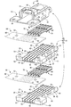
- FIG. 10 is an exploded perspective view of the connector shown in FIG. 9;
- a plate-like housing main body and a groove-like terminal housing provided on the front end side in the lengthwise direction of the housing main body and opening in the upper surface of the housing main body Chamber, and a plurality of connection terminals provided at the ends of a plurality of electric wires and accommodated respectively in the terminal accommodation chamber, and provided on the rear end side in the longitudinal direction of the housing main body, after the terminal accommodation chamber
- It is a connector provided with the cover part which is put together on the above-mentioned upper surface of a housing body, covers the terminal accommodation room, and sandwiches the sheet-like reinforcing member between the wire support part.
- the terminal accommodating chamber provided in the housing main body has a groove shape opening upward
- the step of accommodating the connection terminal provided at the end of the wire is performed to the plurality of terminal accommodating chambers.
- a plurality of connection terminals can be collectively fitted from above, as compared with the conventional case where one connection terminal is accommodated in a cylindrical terminal accommodation chamber surrounded by four peripheral walls. This can dramatically improve the workability.
- the concentration of stress on the wire extending from the terminal storage chamber which is a concern when adopting a terminal storage chamber having a groove shape, is also achieved by the plurality of wires by the wire support portion extending from the rear end side opening of the terminal storage chamber. Is reduced by being supported.
- a plurality of electric wires extending from the rear end side opening of the terminal accommodating chamber are fixed in parallel to the sheet-like reinforcing member and mounted on the upper surface of the electric wire support portion and overlapped on the upper surface of the housing main body
- the sandwiching between the combined cover portion and the upper surface of the housing main body reliably avoids or reduces the application of external force to the plurality of wires, and reliably realizes strength assurance of the wires of such a portion. be able to. Therefore, it is possible to adopt a groove-shaped terminal accommodating chamber even when employing an extremely thin wire as the electric wire.
- the upper surface of the wire support portion is connected to the rear end side opening of the terminal storage chamber to connect the housing main body
- a plurality of grooved electric wire receiving grooves open at the rear end are arranged in parallel with each other and open at the upper surface of the electric wire support portion.
- the wire receiving grooves are opened in the upper surface of the wire support portion in a plurality connected in parallel to the rear end side opening of the terminal receiving chamber, the plurality fixed to the sheet-like reinforcing member It becomes possible to insert the electric wires of the above into the electric wire receiving grooves and to store and hold them.
- the sheet-like reinforcing member can be held without a gap between the wire support portion and the cover portion, and the positional deviation of the sheet-like reinforcing member can be reliably prevented, and the transmission of external force to the wire can be further advantageously achieved. Can be realized and the strength can be secured.
- a positioning protrusion is provided on the upper surface of the wire support portion while the positioning protrusion is provided on the sheet-like reinforcing member. And a first positioning recess in which the positioning projection is fitted into the lower surface of the cover portion.
- the positioning between the wire support portion and the cover portion of the sheet-like reinforcing member is performed by cooperation of the positioning protrusion and the positioning hole of the sheet-like reinforcing member into which they are fitted and the first positioning recess of the cover portion. , Can be done reliably. As a result, the sheet-like reinforcing member is stably held at the predetermined position between the wire support portion and the cover portion, and the strength of the wire can be secured more reliably.
- the sheet-like reinforcing member since the positioning hole of the sheet-like reinforcing member can be fitted into and locked in the positioning protrusion protruding on the upper surface of the wire support portion, the sheet-like reinforcing member is The wire support portion can be stably held, and the workability can be improved.
- a plurality of the housing bodies are stacked in a plurality of upper and lower stages, and are stacked on the lower housing body.
- the lower surface of the upper housing main body is engaged with the upper surface of the lower housing main body to cover the terminal accommodating chamber and hold the sheet-like reinforcing member between the electric wire supporting portion
- the intermediate cover portion is provided with a second positioning recess in which the positioning protrusion protruding from the wire support portion of the lower housing main body is fitted.
- the intermediate cover portion is constituted by the lower surface of the housing main body and the sheet-like reinforcing member can be held between the cover of the terminal storage chamber and the wire support portion, the number of parts can be reduced and the structure can be simplified.
- the cover portion and the housing body are interlocked with each other by a locking mechanism provided on a side wall. It is
- the cover portion and the housing main body are mutually locked by the lock mechanism provided on the side wall, the overlapping state of the cover portion and the housing main body can be stably held. It becomes possible to hold the sheet-like reinforcing member more stably between the wire support portion and the cover portion.
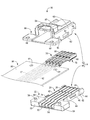
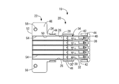
- FIGS. 1-8 A connector 10 according to a first embodiment of the invention is shown in FIGS. 1-8.
- the connector 10 is configured to include a plurality (five in the present embodiment) of electric wires 12 and a connector housing 14 provided at the end of the plurality of electric wires 12 as shown in FIGS. 1 to 3. . And it connects with the other party connector provided in the various electrical components which are not shown in figure from the front side (right side in FIG. 3) of the connector 10.
- the upper side means the upper side in FIGS. 1 and 2 and the lower side means the lower side in FIGS. 1 and 2 and the front means the right side and the rear side in FIG.
- the term “left” in FIG. 3 means “the left side in FIG. 3”
- “longitudinal direction” means the lateral direction in FIG. 3
- width direction means the vertical direction in FIG.
- the connector housing 14 is configured to include the housing main body 16 and the cover portion 18, and each of them is made of, for example, a synthetic resin such as polypropylene (PP) or polyamide (PA) by injection molding or the like. It is integrally formed.
- the housing body 16 is generally plate-shaped.
- a terminal housing portion 20 having a substantially horizontally elongated rectangular shape in plan view is provided on the front end side (right end side in FIG. 6) of the housing main body 16 in the longitudinal direction.
- a wire support portion 22 having a substantially vertically elongated rectangular shape in plan view is provided.
- the terminal accommodating portion 20 is opened in the length direction outward and the upper surface 24 of the housing main body 16 and extends in the longitudinal direction in a substantially rectangular cross-sectional shape and in the width direction (in FIG.
- a plurality of substantially groove-shaped terminal accommodating chambers 26 arranged in parallel with each other in the vertical direction) are provided.
- the central portion in the width direction of the substantially central portion in the longitudinal direction of the bottom surface 28 of the terminal accommodating chamber 26 is mutually separated in the longitudinal direction (lateral direction in FIG. 6) of the terminal accommodating chamber 26 and directed upward.
- a pair of substantially square columnar engaging projections 30, 30 are provided to project. Of the pair of engagement projections 30, 30 at the projecting end of the engagement projection 30 located on the front side (right side in FIG. 6), as shown in FIG.
- An engagement claw 32 projecting in a substantially triangular sectional shape is protruded toward the right).
- the elastic lock claw 34 is configured to include the engagement projection 30 and the engagement claw 32, and the taper is inclined downward as the upper surface 36 of the engagement claw 32 goes outward (right side in FIG. 8). It is considered to be a face.
- the protrusion height dimension of a pair of engagement protrusion 30 and 30 is formed lower on the front side than on the rear side, this will be described later, the core wire caulking portion 76 and the electric wire engaged with each other It is only formed corresponding to the height dimension from the bottom surface 28 of the terminal accommodating chamber 26 of the caulking portion 78.
- the width direction (in FIG. 6) is on the front side (right side in FIGS. 6 and 8) of the elastic lock claw 34 on the bottom surface 28 of the terminal accommodating chamber 26.
- an engagement projection 38 is formed which protrudes in a substantially rectangular shape in plan view.
- an engagement recess 40 opened to the bottom surface 28 of the terminal accommodating chamber 26 is formed (see FIGS. 6 and 8).
- FIGS. 2 and 5 to 6 the front end and the rear end of the side walls 42 and 42 in the width direction (vertical direction in FIG.
- a fitting protrusion 44 is provided which protrudes outward in a substantially rectangular cross-sectional shape and extends upward. Further, between the fitting projections 44 provided on the side walls 42, lock portions 46 which protrude outward and extend in a substantially trapezoidal cross-sectional shape in the longitudinal direction are formed.
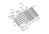
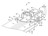
- the upper surface 48 of the wire support 22 is connected to the rear end side opening 50 of the terminal accommodating chamber 26 and at the rear end 52 of the housing main body 16.
- a substantially groove-shaped wire housing groove 54 which opens and extends in a substantially rectangular cross-sectional shape in the length direction is opened on the upper surface 48 of the wire support portion 22 and arranged in parallel in the width direction (vertical direction in FIG. 6) It is done.
- positioning projections 56 are provided in a substantially cylindrical shape.
- the protruding tip of the positioning projection 56 is slightly tapered.
- a second positioning recess 100 described later is provided on the bottom surface of the wire support 22 at a position corresponding to the positioning protrusion 56.
- the cover portion 18 has a substantially block shape, and the upper portion of the cover portion 18 is used to release the engagement between the connector 10 and a mating connector (not shown).
- An engagement release portion 58 is provided.
- An engagement frame 62 is provided.
- fitting recesses 64 opened downward and on both sides in the width direction are provided.
- a sandwiching member which protrudes in a substantially rectangular flat shape toward the rear side (left side in FIG. 3) and extends toward both sides in the width direction (vertical direction in FIG. 3)
- the part 66 is provided on the rear end side of the cover portion 18.
- Through holes 68 penetrating in a substantially circular cross-sectional shape in the vertical direction are formed on both sides in the width direction of the rear end side of the sandwiching portion 66.
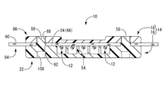
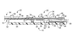
- connection terminals 70 are connected to the ends of the wires 12 respectively. More specifically, the insulation coating 72 on the tip end side (right side in FIG. 8) of the electric wire 12 is peeled off to expose the core wire 74, the core wire 74 is exposed to the core wire caulking portion 76 of the connection terminal 70, and the core wire 74 is exposed.
- the electric wire 12 is fixed and connected to the connection terminal 70 by caulking the tip end portion of the electric wire 12 in the electric wire caulking portion 78 of the connection terminal 70. Further, at the tip end portion (right side in FIG. 8) of the connection terminal 70, a cylindrical connection portion 80 opened in the length direction (left and right direction in FIG. 8) is formed. Then, as shown in FIG.
- connection terminal 70 in the connection terminal 70, a recess 82 opened in a surface opposite to the bottom surface 28 of the terminal accommodation chamber 26 between the core caulking portion 76 and the connection portion 80.
- an engaging portion 83 extending along the outer surface is formed at the lower rear end (the left end in FIG. 8) in FIG.
- an engaging portion 84 extending obliquely outward is formed.
- an elastic contact piece 86 which extends along the inner surface from the rear end portion (left end portion in FIG. 8) at the upper portion in FIG. There is.
- an embossed portion 88 is formed on the inner surface of the connection portion 80 by the inward end of the lower front end side (the right end side in FIG. 8) in FIG.
- the mating connector 89 is connected to the mating connector.
- the mating terminal 89 is described by a virtual line.
- the plurality of electric wires 12 extending from the connection terminal 70 are fixed to the sheet-like reinforcing member 90 in a state of being arranged in parallel.
- a positioning hole 92 having a substantially circular cross-sectional shape is penetrated on both sides in the width direction across the plurality of electric wires 12 on the front end side (right end side in FIG. 7) of the sheet-like reinforcing member 90.
- the electric wire 12 has a structure in which a core wire 74 obtained by bundling a plurality of copper, aluminum and other metal wires as conductors is covered with an insulating coating 72 having electrical insulation such as ethylene resin or styrene resin.
- the connection terminal 70 is integrally formed using various metal materials having conductivity and capable of being pressed or punched, such as brass, copper, copper alloy, aluminum, aluminum alloy, etc. .
- the sheet reinforcing member 90 for example, a glass fiber non-woven fabric, an aramid fiber non-woven fabric or the like impregnated with an epoxy resin or a phenol resin is used to press the sheet reinforcing member 90 against the electric wire 12 by heat press or the like. It is possible to fix by.
- the connector 10 thus configured is assembled as follows. First, the wire bundle with sheet-like reinforcing member 94 fixed to the sheet-like reinforcing member 90 is prepared in a state in which the plurality of electric wires 12 to which the connection terminals 70 are connected are connected in parallel. Then, the plurality of connection terminals 70 provided at the ends of the plurality of electric wires 12 in the sheet-like reinforcing member-attached wire bundle 94 are accommodated and arranged in the terminal accommodation chambers 26 provided in the housing main body 16, and A positioning hole 92 formed in the member 90 is fitted into the positioning projection 56 of the housing main body 16.
- the plurality of electric wires 12 extending from the rear end side opening 50 of the terminal accommodation chamber 26 is accommodated and held in the electric wire accommodation groove 54 provided in the electric wire support 22 and the front end of the sheet-like reinforcing member 90
- the side (right end side in FIG. 7) is placed on the upper surface 24 of the housing main body 16. More specifically, the connection terminal 70 is inserted from above into the terminal accommodating chamber 26 so that the pair of engagement projections 30, 30 are disposed in the recess 82.
- the elastic lock claw 34 formed of the engagement protrusion 30 having the engagement claw 32 positioned on the front side (right side in FIG. 8) is elastically deformed rearward to insert the connection terminal 70 into the terminal storage chamber 26.
- connection terminal 70 when the connection terminal 70 is placed in the terminal storage chamber 26, the elastic lock claw 34 elastically returns, and the engagement claw 32 of the elastic lock claw 34 enters the inner surface of the connection portion 80 of the connection terminal 70.
- the connection terminal 70 is advantageously prevented from coming out of the terminal accommodating chamber 26 (see FIG. 8).
- the pair of engagement projections 30, 30 are inserted into the recess 82 of the connection terminal 70, and the pair of engagement projections 30, 30 and the recess 82 are formed on both sides in the longitudinal direction (left and right direction in FIG. 8).
- connection terminals 70 are positioned and held on both sides in the longitudinal direction.
- the cylindrical connection portion 80 of the connection terminal 70 into which the mating terminal 89 is inserted is disposed on the tip end side (right side in FIG. 8) of the terminal accommodation chamber 26 in the longitudinal direction.
- the elastic lock claw 34 is elastically returned and the engagement claw 32 of the elastic lock claw 34 is engaged with the inner surface of the connection portion 80 of the connection terminal 70, the elastic lock claw 34 is engaged.
- the amount of penetration of the connecting portion 80 into the inner surface of the connecting portion 80 is set in a range that does not interfere with the mating terminal 89.
- the cover portion 18 is superimposed on the upper surface 24 of the housing main body 16 from above, and the positioning projection 56 provided on the housing main body 16 is press-fit into the through hole 68 of the cover portion 18.
- the terminal accommodating chamber 26 of the housing main body 16 is covered by the cover portion 18, and the front end portion of the sheet-like reinforcing member 90 of the sheet-like reinforcing member attached wire bundle 94 covers the wire support portion 22 of the housing main body 16 and the cover It is held between the holding portions 66 of the portion 18.
- a first positioning recess in which the positioning protrusion 56 of the housing main body 16 is fitted is formed in the lower surface of the cover portion 18 by the through hole 68 of the cover portion 18.
- the lock portion 46 constituting the lock mechanism provided in the side wall 42 of the housing main body 16 engages with the through hole 61 of the engagement frame 62 constituting the lock mechanism provided in the side wall 60 of the cover portion 18 It is united. That is, the cover portion 18 and the housing main body 16 are interlocked with each other by the lock mechanisms 62 and 46 provided on the side walls 60 and 42, respectively.
- the fitting protrusion 44 provided on the side wall 42 of the housing main body 16 is fitted into the fitting recess 64 of the engagement frame 62 provided on the side wall 60 of the cover portion 18.
- the overlapping state of the cover portion 18 and the housing main body 16 can be stably held, and the sheet-like reinforcing member 90 can be held by the wire supporting portion 22 of the housing main body 16 and the holding portion 66 of the cover portion 18 It is possible to hold it more stably.
- the connector 10 having such a structure, since the terminal accommodation chamber 26 is formed in a groove shape opening on the upper surface 24 of the housing main body 16, the plurality of electric wires 12 of the sheet-like reinforcing member-attached electric wire bundle 94
- the connection terminals 70 provided at the terminals can be collectively fitted into the plurality of terminal accommodation chambers 26 from above. Therefore, as compared with the conventional case where the connection terminals are accommodated one by one in the cylindrical terminal accommodation chamber surrounded by the circumferential wall in four sides, the workability can be dramatically improved.
- concentration of stress on the electric wire 12 extending from the terminal accommodating chamber 26 of the terminal accommodating portion 20 of the housing main body 16 is also achieved by the grooved electric wire accommodating groove 54 connected to the rear end side opening 50 of the terminal accommodating chamber 26. Is reduced by being housed and held.
- the plurality of electric wires 12 extending from the connection terminal 70 are fixed to the sheet-like reinforcing member 90 in a state of being arranged in parallel, and the front end of the sheet-like reinforcing member 90 And the wire support portion 22 of the housing main body 16.
- the application of external force to the plurality of electric wires 12 is reliably avoided or reduced, and strength assurance of the electric wires 12 at such a portion can be reliably realized. Therefore, even in the case where, for example, an extremely thin wire is adopted as the electric wire 12, it is possible to adopt the groove-shaped terminal accommodating chamber 26.
- the positioning between the housing main body 16, the sheet-like reinforcing member 90 and the cover portion 18 is performed by cooperation of the positioning projection 56 of the housing main body 16, the positioning hole 92 of the sheet-like reinforcing member 90 and the through hole 68 of the cover portion 18. Can be done reliably. Therefore, the sheet-like reinforcing member 90 is stably held at the predetermined position between the housing main body 16 and the cover portion 18, and the strength of the electric wire 12 can be secured more reliably.
- the positioning holes 92 of the sheet-like reinforcing member 90 can be engaged and locked in the positioning protrusions 56 provided on the upper surface 48 of the wire support portion 22, the sheet-like reinforcing member 90 is mounted before mounting the cover portion 18. The wire support portion 22 of the housing main body 16 can be stably held, and the workability can be improved.
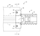
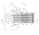
- the housing main body 16 is only one stage, but the housing main bodies 98 and 16 are the same as the connector 96 according to the second embodiment of the present invention shown in FIGS. It may be laminated and constituted up and down. More specifically, as shown in FIGS. 9 to 10, the lower surface of the upper housing main body 98 in which the housing main bodies 98 and 16 are stacked in two upper and lower stages and is superimposed on the lower housing main body 16 Is superimposed on the upper surface 24 of the lower housing body 16 to cover the terminal accommodating chamber 26 of the housing body 16.
- an intermediate cover portion for sandwiching the sheet-like reinforcing member 90 with the wire support portion 22 of the housing main body 16 is constituted by the housing main body 98
- the lower housing main body 16 is provided in the intermediate cover portion.
- a second positioning recess 100 is provided in which the positioning protrusion 56 provided to project from the wire support 22 in the second embodiment is fitted (see FIG. 10). Then, by press-fitting the positioning projection 56 into the second positioning recess 100, the housing main bodies 98 and 16 stacked one on top of the other are positioned and fixed.
- the housing main body 98 disposed between the cover portion 18 and the lowermost housing main body 16 has an engagement frame 62 constituting a lock mechanism in comparison with the lowermost housing main body 16.
- the housing body 16,98 are the same shape. Therefore, it is possible to reduce the mold cost and manufacture the housing body 16,98. Further, when the lock mechanism is not provided, only the housing main body 16 can be used, so that the configuration can be further simplified and the parts management can be facilitated.
- the housing bodies 98 and 16 are stacked in two upper and lower stages, but the number of stages to be stacked can be easily increased by increasing the number of stacked housing bodies 98. be able to.
- the fitting of the positioning protrusion 56 to the through hole 68 and the second positioning recess 100 that constitute the first positioning recess is performed by pressing, but may be inserted, and the sheet in that case
- the sandwiching of the reinforcing member 90 may be constituted by a lock mechanism such as the lock mechanisms 46 and 62, for example.
- the first positioning recess may be the through hole 68 as in the first embodiment, or may be a recess such as the second positioning recess 100.
- the combination of the positioning protrusion 56 and the through hole 68 constituting the first positioning recess and the protrusion and the recess in the second positioning recess 100 may be a combination of the recess and the protrusion. That is, the positioning projection 56 may be provided on the side of the cover body 18 or the housing main body 98 which is an intermediate cover part, and a recess may be formed on the upper surface 24 of the housing main bodies 16 and 98.
- the sheet-like reinforcing member 90 is not limited to the illustrated one, and an adhesive layer is provided on a resin-made sheet material so that the electric wire 12 is fixed, or a wire 12 for a cloth-made sheet material. Any material can be adopted as long as it can fix and hold the electric wire 12 in a sheet shape, such as a material fixed by sawing.
Abstract
上方に開口する溝状の端子収容室を採用した場合でも、端子収容室から延び出す電線の強度を安定して担保することができる、新規な構造のコネクタを提供すること。 プレート状のハウジング本体16と、ハウジング本体16の上面24に開口して複数並列配置された溝状の端子収容室26と、複数の電線12の端末に設けられて端子収容室26にそれぞれ収容配置された複数の接続端子70と、端子収容室26の後端側開口部50から延び出す複数の電線12を支持する電線支持部22と、電線支持部22の上面48に載置されると共に複数の電線12がそれぞれ並列状態で固着されたシート状補強部材90と、ハウジング本体16の上面24に重ね合されて端子収容室26を蓋覆すると共にシート状補強部材90を電線支持部22との間で挟持するカバー部18とを備えているコネクタを提供する。
Description
本発明は、自動車等に配索されるワイヤハーネスに用いられるコネクタに関するものである。
従来から、ワイヤハーネスの端末に取り付けられるコネクタは、ワイヤハーネスを構成する複数の電線端末にそれぞれ設けられた複数の接続端子と、かかる複数の接続端子をそれぞれ収容保持する複数の端子収容室を有するコネクタハウジングを備えている。ところで、コネクタハウジングの端子収容室は四方を周壁部に囲われた筒形状とされていることから、コネクタの製造時には、電線端末に設けられた複数の接続端子を1本ずつ端子収容室に挿入する作業が必要となることから、作業性の悪化を招いていた。
これに対して、例えば、特開2001-230038号公報(特許文献1)に開示されているように、溝状の端子収容室を複数併設したプレート状のハウジングを採用して、ハウジングの上面に開口した複数の溝状の端子収容室に対して、上方から複数の接続端子を挿し入れる作業を行うことにより作業性の向上を図った構造が提案されている。
ところが、このような溝状の端子収容室を採用した場合には、端子収容室の上面が開口していることから、組み付け作業時や使用時において、端子収容室の後端開口部から延び出す電線へ応力が集中し易く、極細線等のように電線の強度自体が弱い場合には、電線の強度を担保し難くなって、溝状の端子収容室を採用すること自体が難しくなる場合があった。
本発明は、上述の事情を背景に為されたものであって、その解決課題は、上方に開口する溝状の端子収容室を採用した場合でも、端子収容室から延び出す電線の強度を安定して担保することができる、新規な構造のコネクタを提供することにある。
本発明の第一の態様は、プレート状のハウジング本体と、前記ハウジング本体の長さ方向の前端側に設けられて、該ハウジング本体の上面に開口して複数並列配置された溝状の端子収容室と、複数の電線の端末に設けられて前記端子収容室にそれぞれ収容配置された複数の接続端子と、前記ハウジング本体の長さ方向の後端側に設けられて、前記端子収容室の後端側開口部から延び出す前記複数の電線を支持する電線支持部と、前記電線支持部の上面に載置されると共に前記複数の電線がそれぞれ並列状態で固着されたシート状補強部材と、前記ハウジング本体の前記上面に重ね合されて前記端子収容室を蓋覆すると共に前記シート状補強部材を前記電線支持部との間で挟持するカバー部とを備えているコネクタである。
本発明によれば、上方に開口する溝状の端子収容室を採用した場合でも、端子収容室から延び出す電線の強度を安定して担保することができるコネクタが提供される。
最初に、本発明の実施態様を列記して説明する。
本発明の第一の態様は、プレート状のハウジング本体と、前記ハウジング本体の長さ方向の前端側に設けられて、該ハウジング本体の上面に開口して複数並列配置された溝状の端子収容室と、複数の電線の端末に設けられて前記端子収容室にそれぞれ収容配置された複数の接続端子と、前記ハウジング本体の長さ方向の後端側に設けられて、前記端子収容室の後端側開口部から延び出す前記複数の電線を支持する電線支持部と、前記電線支持部の上面に載置されると共に前記複数の電線がそれぞれ並列状態で固着されたシート状補強部材と、前記ハウジング本体の前記上面に重ね合されて前記端子収容室を蓋覆すると共に前記シート状補強部材を前記電線支持部との間で挟持するカバー部とを備えているコネクタである。
本態様によれば、ハウジング本体に設けられた端子収容室が上方に開口する溝形状を有していることから、電線の端末に設けられた接続端子を収容する工程を複数の端子収容室に対して複数の接続端子を一括して上方から嵌め入れることが可能となり、従来のように四方を周壁に囲まれた筒形状の端子収容室に1本ずつ接続端子を収容する場合に比して、飛躍的な作業性の向上を図ることができる。さらに、溝形状を有する端子収容室を採用した場合に懸念される端子収容室から延び出す電線への応力の集中も、端子収容室の後端側開口部から延び出す電線支持部により複数の電線が支持されることにより低減されている。加えて、端子収容室の後端側開口部から延び出す複数の電線が、シート状補強部材に並列状態で固着されて電線支持部の上面に載置されており、かつハウジング本体の上面に重ね合されるカバー部とハウジング本体の上面との間で挟持されていることから複数の電線へ外力が加わることが確実に回避乃至は低減されて、かかる部位の電線の強度担保を確実に実現することができる。それゆえ、電線として極細線を採用する場合にも、溝形状の端子収容室を採用することが可能となる。
本発明の第二の態様は、前記第一の態様に記載のものにおいて、前記電線支持部の前記上面には、前記端子収容室の前記後端側開口部に連接して前記ハウジング本体の前記後端に開口する溝状の電線収容溝が、該電線支持部の前記上面に開口して複数並列配置されているものである。
本態様によれば、端子収容室の後端側開口部に連接して電線収容溝が電線支持部の上面に開口して複数並列配置されていることから、シート状補強部材に固着された複数の電線をそれぞれ電線収容溝に嵌め入れて収容保持することが可能となる。これにより、電線支持部とカバー部との間で隙間なくシート状補強部材を挟持することができて、シート状補強部材の位置ずれを確実に防止して、一層有利に電線への外力の伝達の回避や強度確保を実現することができる。
本発明の第三の態様は、前記第一または第二の態様に記載のものにおいて、前記電線支持部の前記上面に位置決め突起が突設されている一方、前記シート状補強部材に前記位置決め突起が嵌め入れられる位置決め穴が貫設されていると共に、前記カバー部の下面に前記位置決め突起が嵌め入れられる第一位置決め凹部が開口形成されているものである。
本態様によれば、シート状補強部材の電線支持部とカバー部との間の位置決めを位置決め突起およびそれらが嵌め入れられるシート状補強部材の位置決め穴およびカバー部の第一位置決め凹部の協働により、確実に行うことができる。これにより、シート状補強部材が電線支持部とカバー部との間の所定位置に安定して保持されて、一層確実に電線の強度を確保することができる。特に電線支持部の上面に突設された位置決め突起にシート状補強部材の位置決め穴を嵌め入れて係止させることができることから、カバー部を装着する前の段階でシート状補強部材をハウジング本体の電線支持部に安定して保持することができ、作業性の向上を図ることができる。
本発明の第四の態様は、前記第一乃至第三の何れか1つの態様に記載のものにおいて、複数の前記ハウジング本体が上下複数段に積層されており、下側の前記ハウジング本体に重ね合される上側の前記ハウジング本体の下面によって、下側の前記ハウジング本体の前記上面に重ね合されて前記端子収容室を蓋覆すると共に前記シート状補強部材を前記電線支持部との間で挟持する中間カバー部が構成されている一方、前記中間カバー部には、下側の前記ハウジング本体における前記電線支持部に突設された位置決め突起が嵌め入れられる第二位置決め凹部が設けられており、該第二位置決め凹部への前記位置決め突起の嵌合により、上下に積層された前記ハウジング本体同士が位置決め固定されるようになっているものである。
本態様によれば、複数のハウジング本体を上下複数段に積層することにより、容易に積層コネクタを設けることができる。特に、ハウジング本体の下面によって中間カバー部が構成されて端子収容室の覆蓋や電線支持部との間におけるシート状補強部材の挟持を行うことができることから、部品点数の削減や構成の簡素化を図ることができる。
本発明の第五の態様は、前記第一乃至第四の何れか1つの態様に記載のものにおいて、前記カバー部と前記ハウジング本体が側壁に設けられたロック機構によって相互にロック嵌合されているものである。
本態様によれば、カバー部とハウジング本体が側壁に設けられたロック機構によって相互にロック嵌合されていることから、カバー部とハウジング本体の重ね合わせ状態を安定して保持することができ、シート状補強部材を電線支持部とカバー部との間で一層安定して挟持することが可能となる。
以下、本発明の実施形態について、図面を参照しつつ説明する。なお、すべての図面において、同様な構成要素には同様の符号を付し、適宜説明を省略する。
図1~8には、本発明の第一の実施形態としてのコネクタ10が、示されている。コネクタ10は、図1~3に示されているように、複数(本実施形態では5本)の電線12と、複数の電線12の端末に設けられたコネクタハウジング14を含んで構成されている。そして、コネクタ10の前方側(図3中、右側)より図示しない各種電装品に設けられた相手側コネクタに連結されるようになっている。なお、以下の説明において、上方とは、図1~2,4中の上方、下方とは、図1~2,4中の下方を言い、また前方とは、図3中の右方、後方とは、図3中の左方を言い、さらに長さ方向とは、図3中の左右方向、幅方向とは、図3中の上下方向を言うものとする。
図2に示されているように、コネクタハウジング14は、ハウジング本体16とカバー部18を備えて構成されており、それぞれ例えばポリプロピレン(PP)、ポリアミド(PA)等の合成樹脂により射出成形等によって一体形成されている。図2および図5~6に示されているように、ハウジング本体16は略プレート状とされている。そして、ハウジング本体16の長さ方向の前端側(図6中、右端側)には、平面視で略横長矩形状の端子収容部20が設けられている一方、ハウジング本体16の長さ方向の後端側(図6中、左端側)には、平面視で略縦長矩形状の電線支持部22が設けられている。より詳細には、端子収容部20には、ハウジング本体16の長さ方向外方および上面24に開口して略矩形断面形状で長さ方向に向かって延出すると共に幅方向(図6中、上下方向)に対して複数並列配置された略溝状の端子収容室26が設けられている。かかる端子収容室26の底面28の長さ方向の略中央部における幅方向の中央部分には、端子収容室26の長手方向(図6中、左右方向)で相互に離隔して上方に向かって突出する略角柱状の一対の係合突起30,30が突設されている。一対の係合突起30,30のうち前方側(図6中、右側)に位置する係合突起30の突出端部には、図8に示されているように、長手方向の外方(図8中、右方)に向かって略三角断面形状で突出する係合爪32が突設されている。そして、かかる係合突起30と係合爪32を含んで弾性ロック爪34が構成されていると共に、係合爪32の上面36が外方(図8中、右側)に行くに従って下方傾斜するテーパ面とされている。なお、一対の係合突起30,30の突出高さ寸法は、前方側の方が後方側より低く形成されているが、これは後述するようにそれぞれが係合する芯線加締め部76と電線加締め部78の端子収容室26の底面28からの高さ寸法に対応して形成されているに過ぎない。
また、図5~6および図8に示されているように、端子収容室26の底面28における弾性ロック爪34の前方側(図6,8中、右側)には、幅方向(図6中、上下方向)の奥側において、平面視で略矩形状に突出する係合突部38が形成されている。さらに、かかる係合突部38の前方側(図6,8中、右側)には、端子収容室26の底面28に開口する係合凹部40が形成されている(図6,8参照)。加えて、図2および図5~6に示されているように、端子収容部20の幅方向(図6中、上下方向)の両側壁42,42の前端部と後端部にはそれぞれ、外方に向かって略矩形断面形状で突出すると共に上方に向かって延び出す嵌合突起44が設けられている。また、各側壁42に設けられた嵌合突起44,44間には、外方に向かって突出し長さ方向に向かって略台形断面形状で延び出すロック部46が形成されている。
一方、図2および図5~6に示されているように、電線支持部22の上面48には、端子収容室26の後端側開口部50に連接すると共にハウジング本体16の後端52に開口して長さ方向に向かって略矩形断面形状で延びる略溝状の電線収容溝54が、電線支持部22の上面48に開口して幅方向(図6中、上下方向)に複数並列配置されている。さらに、電線支持部22の上面48の後端側における幅方向両端部には、位置決め突起56が略円柱形状で突設されている。かかる位置決め突起56の突出先端部は、僅かに先細とされている。加えて、電線支持部22の底面には、位置決め突起56に対応する位置に後述する第二位置決め凹部100が設けられている。
カバー部18は、図1~2に示されているように、略ブロック形状とされており、カバー部18の上部には、コネクタ10と図示しない相手側コネクタとの係合を解除するための係合解除部58が設けられている。また、カバー部18の前端側の両側壁60,60には、長さ方向の略中央部において下方に向かって延出し中央部分に略矩形断面形状の貫通孔61が貫設された略枠体状の係合枠体62が設けられている。一方、かかる側壁60の長さ方向の両端部には、下方および幅方向両側に開口する嵌合凹部64が設けられている。さらに、カバー部18の後端側には、後方側(図3中、左側)に向かって略矩形平板状に突出すると共に幅方向(図3中、上下方向)両側に向かって延出する挟持部66が設けられている。かかる挟持部66の後端側の幅方向両側には、上下方向に略円形断面形状で貫通する貫通孔68が形成されている。
図2,7~8に示されているように、電線12の端末にはそれぞれ接続端子70が接続されている。より詳細には、電線12の先端側(図8中、右側)の絶縁被覆72を剥いで芯線74を露出させ、芯線74を接続端子70の芯線加締め部76に、また芯線74が露出された電線12の先端部分を接続端子70の電線加締め部78に加締め加工することにより、電線12が接続端子70に対して固定・接続される。さらに、接続端子70の先端部(図8中、右側)には、長さ方向(図8中、左右方向)に開口する筒状の接続部80が形成されている。そして、図8に示されているように、接続端子70には、芯線加締め部76と接続部80の間において、端子収容室26の底面28に対向配置される面に開口する凹所82が設けられている。加えて、接続部80の外面には、図8中、下部の後端部(図8中、左端部)において外面に沿って延びる係合部83が形成されている一方、図8中、下部の前端部(図8中、右端部)において外方斜め後方に向かって延びる係合部84が形成されている。また、接続部80の内面には、図8中、上部において後端部(図8中、左端部)から内面に沿って延びると共に内方斜め前方に向かって延びる弾性接触片86が形成されている。さらに、接続部80の内面には、図8中、下部の前端側(図8中、右端側)が内方に向かって突出することによってエンボス部88が形成されている。かかる弾性接触片86とエンボス部88によって相手側端子89を挟持することにより、相手側コネクタと接続されるようになっている。なお、図8では、理解を容易とするため、相手側端子89を仮想線で記載している。さらに、図2に示されているように、接続端子70から延び出す複数の電線12がそれぞれ並列配置された状態でシート状補強部材90に対して固着されている。かかるシート状補強部材90の前端側(図7中、右端側)の複数の電線12を挟んだ幅方向の両側には、略円形断面形状の位置決め穴92が貫設されている。
なお、電線12は、導体である銅やアルミニウムその他の金属線の複数を束ね合わせた芯線74が、エチレン系樹脂やスチレン系樹脂等の電気絶縁性を有する絶縁被覆72で覆われた構造とされている。一方、接続端子70は、導電性を有しかつプレス加工や打抜き加工等が可能な種々の金属材料、例えば真鍮や銅、銅合金、アルミニウム、アルミニウム合金等を用いて一体的に形成されている。さらに、シート状補強部材90として、例えばガラス繊維不織布やアラミド繊維不織布等に対してエポキシ樹脂やフェノール樹脂等を含浸させたものを用いて、ヒートプレス等でシート状補強部材90を電線12に押し付けることにより固着することが可能となっている。
このような構成とされたコネクタ10が、以下のようにして組み立てられる。まず、端末に接続端子70が接続されている複数の電線12がそれぞれ並列配置された状態でシート状補強部材90に対して固着されているシート状補強部材付電線束94を準備する。そして、かかるシート状補強部材付電線束94における複数の電線12の端末に設けられた複数の接続端子70を、ハウジング本体16に設けられた端子収容室26にそれぞれ収容配置すると共に、シート状補強部材90に貫設されている位置決め穴92をハウジング本体16の位置決め突起56に嵌め入れる。この結果、端子収容室26の後端側開口部50から延び出す複数の電線12が、電線支持部22に設けられた電線収容溝54に収容保持されると共に、シート状補強部材90の前端部側(図7中、右端側)がハウジング本体16の上面24に載置される。より詳細には、接続端子70を上方から端子収容室26に対して一対の係合突起30,30が凹所82に配置されるように挿入する。これにより、前方側(図8中、右側)に位置する係合爪32を有する係合突起30からなる弾性ロック爪34が後方側に弾性変形されて接続端子70の端子収容室26への挿入を許容する。続いて、接続端子70が端子収容室26に載置された際には弾性ロック爪34が弾性復帰して弾性ロック爪34の係合爪32が接続端子70の接続部80の内面に入り込んで係合することにより、接続端子70が端子収容室26から上方に抜け出すことが有利に阻止されている(図8参照)。この結果、一対の係合突起30,30が接続端子70の凹所82に挿入配置されて長手方向(図8中、左右方向)の両側で一対の係合突起30,30と凹所82の形成面である芯線加締め部76の前端部と接続部80の後端部がそれぞれ当接することにより、長手方向両側で接続端子70が端子収容室26に対して位置決め保持されている。加えて、端子収容室26の長手方向の先端側(図8中、右側)には、相手側端子89が挿入される接続端子70の筒状の接続部80が配設されている。上述のように、弾性ロック爪34が弾性復帰して弾性ロック爪34の係合爪32が接続端子70の接続部80の内面に入り込んで係合するようになっていることから、弾性ロック爪34の接続部80の内面への入り込み量が相手側端子89に干渉しない範囲に設定されている。
最後に、カバー部18を上方からハウジング本体16の上面24に重ね合わせて、ハウジング本体16に設けられた位置決め突起56をカバー部18の貫通孔68に対して圧入する。この結果、カバー部18によってハウジング本体16の端子収容室26が蓋覆されると共に、シート状補強部材付電線束94のシート状補強部材90の前端部がハウジング本体16の電線支持部22とカバー部18の挟持部66の間で挟持されるようになっている。ここで、ハウジング本体16の位置決め突起56が嵌め入れられる第一位置決め凹部が、カバー部18の貫通孔68によりカバー部18の下面に開口形成されている。さらに、カバー部18の側壁60に設けられたロック機構を構成する係合枠体62の貫通孔61に対して、ハウジング本体16の側壁42に設けられたロック機構を構成するロック部46が係合されている。すなわち、カバー部18とハウジング本体16がそれぞれの側壁60,42に設けられたロック機構62,46によって相互にロック嵌合されているのである。加えて、カバー部18の側壁60に設けられた係合枠体62の嵌合凹部64に対してハウジング本体16の側壁42に設けられた嵌合突起44が嵌め込まれている。以上のことにより、カバー部18とハウジング本体16の重ね合わせ状態を安定して保持することができると共に、シート状補強部材90をハウジング本体16の電線支持部22とカバー部18の挟持部66との間で一層安定して挟持することが可能となっている。
このような構造とされたコネクタ10によれば、端子収容室26がハウジング本体16の上面24に開口する溝形状とされていることから、シート状補強部材付電線束94の複数の電線12の端末に設けられた接続端子70を複数の端子収容室26に対して一括して上方から嵌め入れることが可能となっている。それゆえ、従来の如き四方を周壁に囲まれた筒形状の端子収容室に1本ずつ接続端子を収容する場合に比して、飛躍的な作業性の向上を図ることができる。さらに、ハウジング本体16の端子収容部20の端子収容室26から延び出す電線12に対する応力の集中も、端子収容室26の後端側開口部50に連接する溝状の電線収容溝54によって電線12が収容保持されていることにより低減されている。加えて、接続端子70から延び出す複数の電線12がそれぞれ並列配置された状態でシート状補強部材90に対して固着されると共に、シート状補強部材90の前端部がカバー部18の挟持部66とハウジング本体16の電線支持部22との間で挟持されている。これにより、複数の電線12に対して外力が加わることが確実に回避乃至は低減されており、かかる部位の電線12の強度担保を確実に実現することができる。それゆえ、電線12として例えば極細線を採用する場合であっても、かかる溝形状の端子収容室26を採用することが可能となっている。
また、ハウジング本体16とシート状補強部材90とカバー部18との間の位置決めを、ハウジング本体16の位置決め突起56とシート状補強部材90の位置決め穴92とカバー部18の貫通孔68の協働により、確実に行うことができる。それゆえ、シート状補強部材90がハウジング本体16とカバー部18との間の所定位置に安定して保持されて、一層確実に電線12の強度を確保することができる。特に、電線支持部22の上面48に突設された位置決め突起56にシート状補強部材90の位置決め穴92を嵌め入れて係止できることから、カバー部18を装着する前にシート状補強部材90をハウジング本体16の電線支持部22に安定して保持でき、作業性の向上を図ることができる。
以上、本発明の実施形態について詳述したが、本発明はこれらの具体的な記載によって限定されない。例えば、上記第一の実施形態では、ハウジング本体16は1段のみであったが、図9~10に示す本発明の第二の実施形態としてのコネクタ96のように、ハウジング本体98,16が上下に積層されて構成されていてもよい。より詳細には、図9~10に示されているように、ハウジング本体98,16が上下2段に積層されており、下側のハウジング本体16に重ね合される上側のハウジング本体98の下面が、下側のハウジング本体16の上面24に重ね合されてハウジング本体16の端子収容室26が蓋覆されている。さらに、ハウジング本体98によって、シート状補強部材90をハウジング本体16の電線支持部22との間で挟持する中間カバー部が構成されている一方、かかる中間カバー部には、下側のハウジング本体16における電線支持部22に突設された位置決め突起56が嵌め入れられる第二位置決め凹部100が設けられている(図10参照)。そして、第二位置決め凹部100への位置決め突起56の圧入により、上下に積層されたハウジング本体98,16同士が位置決め固定されるようになっている。
なお、カバー部18と最下層のハウジング本体16の間に配設されるハウジング本体98は、最下層のハウジング本体16に比してロック機構を構成する係合枠体62を有している以外は同一形状である。それゆえ、金型コストを削減してハウジング本体16,98を製造することができる。また、ロック機構を設けない場合には、ハウジング本体16のみの使用とできることから、一層の構成の簡素化や部品管理の容易化を図ることができる。さらに、図9~10に示す本発明の第二の実施形態では、ハウジング本体98,16は上下2段に積層されていたが、積層するハウジング本体98を増やすことにより容易に積層する段数を増やすことができる。
また、上記実施形態では、第一位置決め凹部を構成する貫通孔68や第二位置決め凹部100への位置決め突起56の嵌合は圧入とされていたが挿通とされていてもよく、その場合のシート状補強部材90の挟持は例えばロック機構46,62等のロック機構によって構成されていてもよい。さらに、第一位置決め凹部は、上記第一の実施形態のように貫通孔68であってもよいし、第二位置決め凹部100のような凹所であってもよい。加えて、位置決め突起56と第一位置決め凹部を構成する貫通孔68と第二位置決め凹部100における凸部と凹部の組合せは、逆に凹部と凸部の組合せであってもよい。すなわち、カバー部18や中間カバー部であるハウジング本体98側に位置決め突起56が設けられ、ハウジング本体16,98の上面24に凹部が形成されていてもよい。
加えて、シート状補強部材90は例示のものに限定されず、樹脂製のシート材に接着層が設けられて電線12が固着されるようにしたものや、布製のシート材に対して電線12をソーイングにより固着したもの等、シート状で電線12を固着保持できるものであれば任意のものが採用可能である。
10,96:コネクタ、12:電線、16:ハウジング本体、18:カバー部、22:電線支持部、24:上面、26:端子収容室、46:ロック部(ロック機構)、48:上面、50:後端側開口部、52:後端、54:電線収容溝、56:位置決め突起、62:係合枠体(ロック機構)、68:貫通孔(第一位置決め凹部)、70:接続端子、90:シート状補強部材、92:位置決め穴、98:ハウジング本体(中間カバー部)、100:第二位置決め凹部
Claims (5)
- プレート状のハウジング本体と、
前記ハウジング本体の長さ方向の前端側に設けられて、該ハウジング本体の上面に開口して複数並列配置された溝状の端子収容室と、
複数の電線の端末に設けられて前記端子収容室にそれぞれ収容配置された複数の接続端子と、
前記ハウジング本体の長さ方向の後端側に設けられて、前記端子収容室の後端側開口部から延び出す前記複数の電線を支持する電線支持部と、
前記電線支持部の上面に載置されると共に前記複数の電線がそれぞれ並列状態で固着されたシート状補強部材と、
前記ハウジング本体の前記上面に重ね合されて前記端子収容室を蓋覆すると共に前記シート状補強部材を前記電線支持部との間で挟持するカバー部とを備えているコネクタ。 - 前記電線支持部の前記上面には、前記端子収容室の前記後端側開口部に連接して前記ハウジング本体の前記後端に開口する溝状の電線収容溝が、該電線支持部の前記上面に開口して複数並列配置されている請求項1に記載のコネクタ。
- 前記電線支持部の前記上面に位置決め突起が突設されている一方、前記シート状補強部材に前記位置決め突起が嵌め入れられる位置決め穴が貫設されていると共に、前記カバー部の下面に前記位置決め突起が嵌め入れられる第一位置決め凹部が開口形成されている請求項1または2に記載のコネクタ。
- 複数の前記ハウジング本体が上下複数段に積層されており、下側の前記ハウジング本体に重ね合される上側の前記ハウジング本体の下面によって、下側の前記ハウジング本体の前記上面に重ね合されて前記端子収容室を蓋覆すると共に前記シート状補強部材を前記電線支持部との間で挟持する中間カバー部が構成されている一方、
前記中間カバー部には、下側の前記ハウジング本体における前記電線支持部に突設された位置決め突起が嵌め入れられる第二位置決め凹部が設けられており、該第二位置決め凹部への前記位置決め突起の嵌合により、上下に積層された前記ハウジング本体同士が位置決め固定されるようになっている請求項1~3の何れか1項に記載のコネクタ。 - 前記カバー部と前記ハウジング本体が側壁に設けられたロック機構によって相互にロック嵌合されている請求項1~4の何れか1項に記載のコネクタ。
Priority Applications (3)
| Application Number | Priority Date | Filing Date | Title |
|---|---|---|---|
| US16/960,429 US11245220B2 (en) | 2018-01-22 | 2018-10-22 | Connector including sandwiched configuration |
| DE112018006913.3T DE112018006913T5 (de) | 2018-01-22 | 2018-10-22 | Verbinder |
| CN201880087227.0A CN111656620B (zh) | 2018-01-22 | 2018-10-22 | 连接器 |
Applications Claiming Priority (2)
| Application Number | Priority Date | Filing Date | Title |
|---|---|---|---|
| JP2018-007953 | 2018-01-22 | ||
| JP2018007953A JP6669996B2 (ja) | 2018-01-22 | 2018-01-22 | コネクタ |
Publications (1)
| Publication Number | Publication Date |
|---|---|
| WO2019142422A1 true WO2019142422A1 (ja) | 2019-07-25 |
Family
ID=67302069
Family Applications (1)
| Application Number | Title | Priority Date | Filing Date |
|---|---|---|---|
| PCT/JP2018/039127 WO2019142422A1 (ja) | 2018-01-22 | 2018-10-22 | コネクタ |
Country Status (5)
| Country | Link |
|---|---|
| US (1) | US11245220B2 (ja) |
| JP (1) | JP6669996B2 (ja) |
| CN (1) | CN111656620B (ja) |
| DE (1) | DE112018006913T5 (ja) |
| WO (1) | WO2019142422A1 (ja) |
Cited By (2)
| Publication number | Priority date | Publication date | Assignee | Title |
|---|---|---|---|---|
| WO2021079587A1 (ja) * | 2019-10-24 | 2021-04-29 | 株式会社オートネットワーク技術研究所 | ジョイントコネクタ |
| WO2022075045A1 (ja) * | 2020-10-07 | 2022-04-14 | 住友電装株式会社 | 配線部材 |
Families Citing this family (1)
| Publication number | Priority date | Publication date | Assignee | Title |
|---|---|---|---|---|
| JP6601537B1 (ja) * | 2018-06-27 | 2019-11-06 | 株式会社オートネットワーク技術研究所 | 配線部材の固定構造 |
Citations (7)
| Publication number | Priority date | Publication date | Assignee | Title |
|---|---|---|---|---|
| JPH04329270A (ja) * | 1991-04-30 | 1992-11-18 | Fujitsu Ltd | ケーブル接続用コネクタの組立方法 |
| JPH05266935A (ja) * | 1991-04-19 | 1993-10-15 | Fujitsu Ltd | ケーブル接続用コネクタ |
| JPH09129307A (ja) * | 1995-11-01 | 1997-05-16 | Harness Sogo Gijutsu Kenkyusho:Kk | コネクタへのケーブル接続方法及び接続構造並びに接続用補強部材 |
| JP2001060477A (ja) * | 1999-08-23 | 2001-03-06 | Sumitomo Wiring Syst Ltd | 電線のコネクタ接続構造 |
| JP2001230038A (ja) * | 2000-02-15 | 2001-08-24 | Yazaki Corp | 積層プレートコネクタの製造方法 |
| JP2002158061A (ja) * | 2000-11-16 | 2002-05-31 | Sumitomo Wiring Syst Ltd | ワイヤーハーネスの保護構造 |
| JP2005190717A (ja) * | 2003-12-24 | 2005-07-14 | Fujikura Ltd | フラットハーネス用コネクタ |
Family Cites Families (10)
| Publication number | Priority date | Publication date | Assignee | Title |
|---|---|---|---|---|
| GB2261558B (en) * | 1991-10-31 | 1996-07-10 | Sumitomo Wiring Systems | A connector assembly |
| JP3775557B2 (ja) * | 1999-11-04 | 2006-05-17 | 住友電装株式会社 | コネクタ |
| JP2002110295A (ja) | 2000-10-02 | 2002-04-12 | Tyco Electronics Amp Kk | 電気コネクタ組立体およびこれに用いられる雄コネクタ |
| US6926562B1 (en) | 2004-02-09 | 2005-08-09 | Hon Hai Precision Ind. Co., Ltd. | Cable end connector assembly with improved spacer |
| JP2006294386A (ja) * | 2005-04-08 | 2006-10-26 | Tyco Electronics Amp Kk | 電気コネクタ、ワイヤハーネス及びワイヤハーネスの配置方法 |
| EP2023445B1 (en) * | 2007-08-10 | 2012-07-25 | Sumitomo Wiring Systems, Ltd. | A joint connector and an assembling method therefor |
| US7798821B2 (en) * | 2008-02-01 | 2010-09-21 | Hon Hai Precision Ind. Co., Ltd | Cable assembly with an organizer for adjusting the cable outlet |
| JP6669997B2 (ja) * | 2018-01-22 | 2020-03-18 | 株式会社オートネットワーク技術研究所 | コネクタ |
| JP6832313B2 (ja) * | 2018-07-23 | 2021-02-24 | 矢崎総業株式会社 | フレキシブルプリント配線板のコネクタ取付構造 |
| JP6820297B2 (ja) * | 2018-07-31 | 2021-01-27 | 矢崎総業株式会社 | コネクタ付き回路体、及び、バスバモジュール |
-
2018
- 2018-01-22 JP JP2018007953A patent/JP6669996B2/ja active Active
- 2018-10-22 WO PCT/JP2018/039127 patent/WO2019142422A1/ja active Application Filing
- 2018-10-22 CN CN201880087227.0A patent/CN111656620B/zh active Active
- 2018-10-22 US US16/960,429 patent/US11245220B2/en active Active
- 2018-10-22 DE DE112018006913.3T patent/DE112018006913T5/de active Pending
Patent Citations (7)
| Publication number | Priority date | Publication date | Assignee | Title |
|---|---|---|---|---|
| JPH05266935A (ja) * | 1991-04-19 | 1993-10-15 | Fujitsu Ltd | ケーブル接続用コネクタ |
| JPH04329270A (ja) * | 1991-04-30 | 1992-11-18 | Fujitsu Ltd | ケーブル接続用コネクタの組立方法 |
| JPH09129307A (ja) * | 1995-11-01 | 1997-05-16 | Harness Sogo Gijutsu Kenkyusho:Kk | コネクタへのケーブル接続方法及び接続構造並びに接続用補強部材 |
| JP2001060477A (ja) * | 1999-08-23 | 2001-03-06 | Sumitomo Wiring Syst Ltd | 電線のコネクタ接続構造 |
| JP2001230038A (ja) * | 2000-02-15 | 2001-08-24 | Yazaki Corp | 積層プレートコネクタの製造方法 |
| JP2002158061A (ja) * | 2000-11-16 | 2002-05-31 | Sumitomo Wiring Syst Ltd | ワイヤーハーネスの保護構造 |
| JP2005190717A (ja) * | 2003-12-24 | 2005-07-14 | Fujikura Ltd | フラットハーネス用コネクタ |
Cited By (5)
| Publication number | Priority date | Publication date | Assignee | Title |
|---|---|---|---|---|
| WO2021079587A1 (ja) * | 2019-10-24 | 2021-04-29 | 株式会社オートネットワーク技術研究所 | ジョイントコネクタ |
| JPWO2021079587A1 (ja) * | 2019-10-24 | 2021-04-29 | ||
| CN114503373A (zh) * | 2019-10-24 | 2022-05-13 | 株式会社自动网络技术研究所 | 接头连接器 |
| JP7177995B2 (ja) | 2019-10-24 | 2022-11-25 | 株式会社オートネットワーク技術研究所 | ジョイントコネクタ |
| WO2022075045A1 (ja) * | 2020-10-07 | 2022-04-14 | 住友電装株式会社 | 配線部材 |
Also Published As
| Publication number | Publication date |
|---|---|
| JP6669996B2 (ja) | 2020-03-18 |
| JP2019128996A (ja) | 2019-08-01 |
| US11245220B2 (en) | 2022-02-08 |
| DE112018006913T5 (de) | 2020-10-01 |
| CN111656620B (zh) | 2021-08-10 |
| US20200373702A1 (en) | 2020-11-26 |
| CN111656620A (zh) | 2020-09-11 |
Similar Documents
| Publication | Publication Date | Title |
|---|---|---|
| WO2019142442A1 (ja) | コネクタ | |
| WO2019142422A1 (ja) | コネクタ | |
| WO2014030626A1 (ja) | 電子部品、電子部品と端子金具との接続構造、電子部品を有する電気接続箱 | |
| JP2019128997A5 (ja) | ||
| JPH0785429B2 (ja) | テレホンモジユラ−ジヤツク | |
| JP5414836B2 (ja) | コネクタ | |
| JPH0718128Y2 (ja) | 多極コネクタ | |
| JP2019128996A5 (ja) | ||
| JP6955228B2 (ja) | コネクタ | |
| JPH04136870U (ja) | 圧接コネクタ | |
| JP2019122114A (ja) | 電線用外装体及び外装体付きワイヤーハーネス | |
| JP2013093226A (ja) | ジョイントコネクタ | |
| JP6974805B2 (ja) | コネクタ | |
| JP7042580B2 (ja) | コネクタ、ハウジング、カバー体、及びコネクタ付ワイヤーハーネス | |
| JP2001110466A (ja) | 圧接コネクタ | |
| JP7256094B2 (ja) | ジョイントコネクタ | |
| JP6914529B2 (ja) | 電気コネクタ | |
| JP3994820B2 (ja) | ジョイントコネクタおよびジョイントコネクタ合体ユニット | |
| WO2022202183A1 (ja) | ジョイントコネクタ、コネクタ付電線及びコネクタケース | |
| JP2001286030A (ja) | 電気接続箱 | |
| JP2001230038A (ja) | 積層プレートコネクタの製造方法 | |
| JP2024044829A (ja) | 接続金具保持部材、接続金具付電線及び電池モジュール | |
| JP2021163533A (ja) | コネクタ | |
| TW200527766A (en) | Socket connector | |
| WO2019167617A1 (ja) | コネクタ |
Legal Events
| Date | Code | Title | Description |
|---|---|---|---|
| 121 | Ep: the epo has been informed by wipo that ep was designated in this application |
Ref document number: 18901374 Country of ref document: EP Kind code of ref document: A1 |
|
| 122 | Ep: pct application non-entry in european phase |
Ref document number: 18901374 Country of ref document: EP Kind code of ref document: A1 |