WO2022202183A1 - ジョイントコネクタ、コネクタ付電線及びコネクタケース - Google Patents
ジョイントコネクタ、コネクタ付電線及びコネクタケース Download PDFInfo
- Publication number
- WO2022202183A1 WO2022202183A1 PCT/JP2022/009073 JP2022009073W WO2022202183A1 WO 2022202183 A1 WO2022202183 A1 WO 2022202183A1 JP 2022009073 W JP2022009073 W JP 2022009073W WO 2022202183 A1 WO2022202183 A1 WO 2022202183A1
- Authority
- WO
- WIPO (PCT)
- Prior art keywords
- connector
- side plate
- engaging
- plate portion
- cases
- Prior art date
Links
- 210000000078 claw Anatomy 0.000 claims abstract description 69
- 238000010030 laminating Methods 0.000 abstract 1
- 230000004048 modification Effects 0.000 abstract 1
- 238000012986 modification Methods 0.000 abstract 1
- 238000000034 method Methods 0.000 description 4
- 239000004020 conductor Substances 0.000 description 3
- 230000013011 mating Effects 0.000 description 3
- 238000002788 crimping Methods 0.000 description 2
- 230000000694 effects Effects 0.000 description 2
- 239000012212 insulator Substances 0.000 description 2
- 238000005452 bending Methods 0.000 description 1
- 238000010586 diagram Methods 0.000 description 1
- 230000001105 regulatory effect Effects 0.000 description 1
- 229920003002 synthetic resin Polymers 0.000 description 1
- 239000000057 synthetic resin Substances 0.000 description 1
Images


Classifications
-
- H—ELECTRICITY
- H01—ELECTRIC ELEMENTS
- H01R—ELECTRICALLY-CONDUCTIVE CONNECTIONS; STRUCTURAL ASSOCIATIONS OF A PLURALITY OF MUTUALLY-INSULATED ELECTRICAL CONNECTING ELEMENTS; COUPLING DEVICES; CURRENT COLLECTORS
- H01R13/00—Details of coupling devices of the kinds covered by groups H01R12/70 or H01R24/00 - H01R33/00
- H01R13/46—Bases; Cases
- H01R13/514—Bases; Cases composed as a modular blocks or assembly, i.e. composed of co-operating parts provided with contact members or holding contact members between them
-
- H—ELECTRICITY
- H01—ELECTRIC ELEMENTS
- H01R—ELECTRICALLY-CONDUCTIVE CONNECTIONS; STRUCTURAL ASSOCIATIONS OF A PLURALITY OF MUTUALLY-INSULATED ELECTRICAL CONNECTING ELEMENTS; COUPLING DEVICES; CURRENT COLLECTORS
- H01R13/00—Details of coupling devices of the kinds covered by groups H01R12/70 or H01R24/00 - H01R33/00
- H01R13/46—Bases; Cases
- H01R13/502—Bases; Cases composed of different pieces
- H01R13/508—Bases; Cases composed of different pieces assembled by a separate clip or spring
-
- H—ELECTRICITY
- H01—ELECTRIC ELEMENTS
- H01R—ELECTRICALLY-CONDUCTIVE CONNECTIONS; STRUCTURAL ASSOCIATIONS OF A PLURALITY OF MUTUALLY-INSULATED ELECTRICAL CONNECTING ELEMENTS; COUPLING DEVICES; CURRENT COLLECTORS
- H01R31/00—Coupling parts supported only by co-operation with counterpart
- H01R31/08—Short-circuiting members for bridging contacts in a counterpart
-
- H—ELECTRICITY
- H01—ELECTRIC ELEMENTS
- H01R—ELECTRICALLY-CONDUCTIVE CONNECTIONS; STRUCTURAL ASSOCIATIONS OF A PLURALITY OF MUTUALLY-INSULATED ELECTRICAL CONNECTING ELEMENTS; COUPLING DEVICES; CURRENT COLLECTORS
- H01R11/00—Individual connecting elements providing two or more spaced connecting locations for conductive members which are, or may be, thereby interconnected, e.g. end pieces for wires or cables supported by the wire or cable and having means for facilitating electrical connection to some other wire, terminal, or conductive member, blocks of binding posts
- H01R11/03—Individual connecting elements providing two or more spaced connecting locations for conductive members which are, or may be, thereby interconnected, e.g. end pieces for wires or cables supported by the wire or cable and having means for facilitating electrical connection to some other wire, terminal, or conductive member, blocks of binding posts characterised by the relationship between the connecting locations
- H01R11/05—Individual connecting elements providing two or more spaced connecting locations for conductive members which are, or may be, thereby interconnected, e.g. end pieces for wires or cables supported by the wire or cable and having means for facilitating electrical connection to some other wire, terminal, or conductive member, blocks of binding posts characterised by the relationship between the connecting locations the connecting locations having different types of direct connections
-
- H—ELECTRICITY
- H01—ELECTRIC ELEMENTS
- H01R—ELECTRICALLY-CONDUCTIVE CONNECTIONS; STRUCTURAL ASSOCIATIONS OF A PLURALITY OF MUTUALLY-INSULATED ELECTRICAL CONNECTING ELEMENTS; COUPLING DEVICES; CURRENT COLLECTORS
- H01R12/00—Structural associations of a plurality of mutually-insulated electrical connecting elements, specially adapted for printed circuits, e.g. printed circuit boards [PCB], flat or ribbon cables, or like generally planar structures, e.g. terminal strips, terminal blocks; Coupling devices specially adapted for printed circuits, flat or ribbon cables, or like generally planar structures; Terminals specially adapted for contact with, or insertion into, printed circuits, flat or ribbon cables, or like generally planar structures
- H01R12/50—Fixed connections
- H01R12/59—Fixed connections for flexible printed circuits, flat or ribbon cables or like structures
- H01R12/63—Fixed connections for flexible printed circuits, flat or ribbon cables or like structures connecting to another shape cable
-
- H—ELECTRICITY
- H01—ELECTRIC ELEMENTS
- H01R—ELECTRICALLY-CONDUCTIVE CONNECTIONS; STRUCTURAL ASSOCIATIONS OF A PLURALITY OF MUTUALLY-INSULATED ELECTRICAL CONNECTING ELEMENTS; COUPLING DEVICES; CURRENT COLLECTORS
- H01R12/00—Structural associations of a plurality of mutually-insulated electrical connecting elements, specially adapted for printed circuits, e.g. printed circuit boards [PCB], flat or ribbon cables, or like generally planar structures, e.g. terminal strips, terminal blocks; Coupling devices specially adapted for printed circuits, flat or ribbon cables, or like generally planar structures; Terminals specially adapted for contact with, or insertion into, printed circuits, flat or ribbon cables, or like generally planar structures
- H01R12/50—Fixed connections
- H01R12/59—Fixed connections for flexible printed circuits, flat or ribbon cables or like structures
- H01R12/65—Fixed connections for flexible printed circuits, flat or ribbon cables or like structures characterised by the terminal
- H01R12/69—Fixed connections for flexible printed circuits, flat or ribbon cables or like structures characterised by the terminal deformable terminals, e.g. crimping terminals
-
- H—ELECTRICITY
- H01—ELECTRIC ELEMENTS
- H01R—ELECTRICALLY-CONDUCTIVE CONNECTIONS; STRUCTURAL ASSOCIATIONS OF A PLURALITY OF MUTUALLY-INSULATED ELECTRICAL CONNECTING ELEMENTS; COUPLING DEVICES; CURRENT COLLECTORS
- H01R12/00—Structural associations of a plurality of mutually-insulated electrical connecting elements, specially adapted for printed circuits, e.g. printed circuit boards [PCB], flat or ribbon cables, or like generally planar structures, e.g. terminal strips, terminal blocks; Coupling devices specially adapted for printed circuits, flat or ribbon cables, or like generally planar structures; Terminals specially adapted for contact with, or insertion into, printed circuits, flat or ribbon cables, or like generally planar structures
- H01R12/70—Coupling devices
- H01R12/77—Coupling devices for flexible printed circuits, flat or ribbon cables or like structures
- H01R12/771—Details
-
- H—ELECTRICITY
- H01—ELECTRIC ELEMENTS
- H01R—ELECTRICALLY-CONDUCTIVE CONNECTIONS; STRUCTURAL ASSOCIATIONS OF A PLURALITY OF MUTUALLY-INSULATED ELECTRICAL CONNECTING ELEMENTS; COUPLING DEVICES; CURRENT COLLECTORS
- H01R4/00—Electrically-conductive connections between two or more conductive members in direct contact, i.e. touching one another; Means for effecting or maintaining such contact; Electrically-conductive connections having two or more spaced connecting locations for conductors and using contact members penetrating insulation
- H01R4/10—Electrically-conductive connections between two or more conductive members in direct contact, i.e. touching one another; Means for effecting or maintaining such contact; Electrically-conductive connections having two or more spaced connecting locations for conductors and using contact members penetrating insulation effected solely by twisting, wrapping, bending, crimping, or other permanent deformation
- H01R4/18—Electrically-conductive connections between two or more conductive members in direct contact, i.e. touching one another; Means for effecting or maintaining such contact; Electrically-conductive connections having two or more spaced connecting locations for conductors and using contact members penetrating insulation effected solely by twisting, wrapping, bending, crimping, or other permanent deformation by crimping
- H01R4/183—Electrically-conductive connections between two or more conductive members in direct contact, i.e. touching one another; Means for effecting or maintaining such contact; Electrically-conductive connections having two or more spaced connecting locations for conductors and using contact members penetrating insulation effected solely by twisting, wrapping, bending, crimping, or other permanent deformation by crimping for cylindrical elongated bodies, e.g. cables having circular cross-section
Definitions
- the present invention relates to joint connectors, electric wires with connectors, and connector cases.
- the joint connectors disclosed in these patent documents have case holders that accommodate stacked connector cases. Therefore, the number of stacked connector cases is limited to the maximum number that can be accommodated in the case holder. Therefore, there has been a demand for a joint connector in which the number of stacked connector cases is not limited and the number of terminals can be easily and freely changed.
- An object of the present invention is to provide a joint connector in which the number of stacked connector cases is not limited and the number of terminals can be easily and freely changed.
- the present invention is a joint connector constructed by stacking connector cases containing h, wherein the connector case includes a main plate portion for holding the connection terminals, and a main plate portion that is perpendicular to the main plate portion and parallel to each other.
- the inner surface of the tip portion of each of the side plate portions is provided with an engaging claw that protrudes in a direction approaching the opposing side plate portion or recesses in a direction away from the opposing side plate portion
- Engagement grooves are provided, and on the outer surface of the base end portion of each of the side plates, there are provided engagement grooves that are recessed in a direction approaching the opposing side plate portion or engagement claws that protrude in a direction away from the opposing side plate portion. and wherein the engaging claws of one of the connector cases and the engaging grooves of the other connector case are laminated while being engaged with each other.
- the tip portion of the side plate portion means the end portion of the side plate portion on the separated side away from the main plate portion
- the base end portion of the side plate portion means the end portion of the side plate portion on the adjacent side that is close to the main plate portion.
- the inner surface means the wall surface on the side of the internal space in which the connection terminals are accommodated
- the outer surface means the wall surface on the side opposite to the internal space.
- the number of stacked connector cases is not limited, and the number of terminals can be easily and freely changed.
- the inner surface of the tip portion of each side plate portion has an engaging claw projecting in a direction approaching the opposing side plate portion or an engaging claw recessed in a direction away from the opposing side plate portion. Grooves are provided, and the outer surface of the base end portion of each side plate portion is provided with an engagement groove that is recessed in a direction approaching the opposing side plate portion or an engagement claw that protrudes in a direction away from the opposing side plate portion. . Then, the engaging claws of one connector case and the engaging grooves of the other connector case are engaged with each other and stacked.
- another connector case can be stacked on the connector case at the end of the connector cases that constitute the joint connector. Further, by pressing the engaging claws of one connector case and the engaging grooves of the other connector case in parallel with each other, the connector cases can be easily stacked. Therefore, the number of stacked connector cases is not limited, and the number of terminals can be easily and freely changed.
- the engaging claws or the engaging grooves are provided at the tip portion of each of the side plate portions between one side end face and a midway portion in the direction along the main plate portion and the side plate portions.
- the engaging groove or the engaging claw is provided in the base end portion of each of the side plate portions between one side end surface and a midway portion in the direction along the main plate portion and the side plate portions, The stacking may be performed in a state where the other side end face of the engaging claw in the connector case and the other side end face of the engaging groove in the other connector case are in contact with each other.
- the connector cases in stacking the connector cases, can be stacked without deviation by aligning the other side end face of the engaging claw and the other side end face of the engaging groove with each other and pushing them in. .
- the engaging claws and the engaging grooves are provided relatively long with respect to the length of one side of the side plate portion, the length of mutual engagement can be ensured, so that the connector cases can be stacked firmly. .
- the length of engagement by each other can be ensured, rattling of the stacked connector cases can be suppressed.
- an extension portion having the engaging claw or the engaging groove is provided at the tip portion of each of the side plate portions from one side end face in the direction along the main plate portion and the side plate portion to a midway portion.
- a stepped portion having the engaging groove or the engaging pawl is provided between the main plate portion and the side plate portion in the direction along the main plate portion and the side plate portion from the one side end surface to the intermediate portion at the base end portion of each side plate portion.
- the extension portion of one connector case may be provided between the two connector cases, and the other end surface of the extension portion of the other connector case may be in contact with the other end surface of the stepped portion of the other connector case.
- an inner plate parallel to the side plate portion is provided on the inner surface of the main plate portion, and an outer side plate perpendicular to the side plate portion is provided on the outer surface of the main plate portion.
- a plate may be provided, and the inner plate of one of the connector cases may be laminated with the one-side end face of the inner plate and the other-side plane of the outer plate of the other connector case in contact with each other.
- the inner surface of the main plate portion means the wall surface of the main plate portion on the side of the internal space where the connection terminals are accommodated
- the outer surface of the main plate portion means the wall surface of the main plate portion on the opposite side of the internal space.
- the connector cases in the stacking operation of the connector cases, can be stacked without any deviation by aligning the one side end surface of the inner plate and the other side flat surface of the outer plate and pushing them into contact positions.
- the inner plate and the outer plate are in vertical contact with the engaging claws and the engaging groove that engage from one side to the other side, it is possible to suppress rattling of the stacked connector cases.
- the engaging claws and engaging grooves are provided from one side to the other side, there is a possibility that rattling may occur in this direction. are in contact with each other along a direction perpendicular to this direction, it is possible to restrict the movement of each other toward one side or the other, thereby suppressing rattling of the stacked connector cases.
- an inner engaging piece protruding to one side is provided on one side end surface of the inner plate, and an outer engaging piece protruding to the other side is provided on the other side plane of the outer plate.
- the inner engaging piece of one of the connector cases and the outer engaging piece of the other connector case may be stacked while being engaged with each other.
- the inner engaging piece of one connector case and the outer engaging piece of the other connector case are engaged with each other, it is possible to suppress rattling of the stacked connector cases.
- the connector cases are stacked in the stacking direction, there is a possibility that rattling may occur in this direction. Since they are engaged along a vertical direction, it is possible to restrict the movement of the connector cases toward or away from each other, thereby suppressing rattling of the stacked connector cases.
- the connector case accommodates a plurality of connection terminals parallel to a direction from one side to the other side, and the two non-conductive inner plates are adjacent to each other. It may be arranged along the connection terminals between the connection terminals.
- the non-conductive inner plate is arranged along the connection terminal between two adjacent connection terminals, it is possible to prevent short circuits between the adjacent connection terminals. Also, in the work of housing the connection terminals in the connector case, the work is simplified because the inner plate functions as a guide plate.
- each of the side plate portions is provided with a widened portion protruding in a direction approaching the opposing side plate portion, and the tip surface of the widened portion is the engaging claw.
- it may be formed in parallel with the engaging groove at a constant interval.
- the pushed-in main plate portion abuts against the tip surface of the widened portion and is supported along this tip surface, so that these connector cases can be stacked without tilting.
- each of the side plate portions is provided with a projecting portion projecting in a direction away from the opposing side plate portion on the outer surface thereof, and each of the projecting portions in the stacked connector cases may constitute a guide passage for the band clamp.
- the stacked connector cases can be bundled using the band clamp.
- the stacked connector cases can be fixed together with a band clamp to an object to be fixed.
- an electric wire with a connector may be provided, which includes the joint connector according to the present invention and electric wires connected to the connection terminals of the connector case constituting the joint connector.
- the joint connector in the present invention is a concept that includes all the joint connectors according to the inventions described above.
- the electric wire on one side and the electric wire on the other side, which are connected by the connection terminal are different, they can be configured as an electric cable that electrically connects them.
- an electric cable it is possible to prevent the electric wires from coming loose or getting entangled and to simply put them together.
- the electric wire on at least one side may be a flexible flat cable.
- the flexible flat cable in the present invention is a concept that includes all conductors arranged in parallel and sandwiched between sheet-like insulators.
- a connector case for housing connection terminals comprising a main plate portion for holding the connection terminals, and a pair of side plate portions perpendicular to the main plate portion and parallel to each other,
- the inner surface of the tip portion of each of the side plates is provided with an engaging claw projecting in a direction approaching the opposing side plate or an engaging groove recessed in a direction away from the opposing side plate.
- the outer surface of the proximal end portion is provided with an engaging groove recessed in a direction approaching the opposing side plate portion or an engaging claw projecting in a direction away from the opposing side plate portion.
- the aforementioned effects can be obtained for a joint connector configured by stacking connector cases. That is, the number of stacked connector cases is not limited, and the number of terminals can be easily and freely changed.
- FIG. 3 is a perspective view of a connector case that constitutes the joint connector; The front view seen from the direction of arrow A in FIG. The top view seen from the direction of arrow B in FIG. The side view seen from the direction of arrow C in FIG. XX arrow sectional view in FIG. Assembly explanatory drawing of a joint connector. Assembly explanatory drawing of a joint connector.
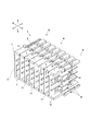
- the connector-equipped electric wire 1 is formed by electrically connecting a plurality of flexible flat cables 2 and a plurality of covered cables 3 via joint connectors 4 .
- the flexible flat cable 2 and the coated cable 3 are one aspect of electric wires.
- the joint connector 4 is constructed by stacking connector cases 10 .
- Each connector case 10 is made of a non-conductive synthetic resin and can accommodate the connection terminals 20 .
- the connector case 10 and the connection terminals 20 will be described in detail below.
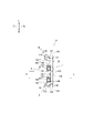
- the connector case 10 has a main plate portion 11, an upper side plate portion 12, and a lower side plate portion 13.
- the space surrounded by the main plate portion 11, the upper side plate portion 12, and the lower side plate portion 13 is defined as an internal space S.
- the internal space S can accommodate one to four connection terminals 20 .
- the main plate portion 11 is provided with a single outer plate 113 projecting rearward from the outer surface thereof.
- the outer plate 113 is arranged slightly to the left of the middle portion in the horizontal direction and parallel to the vertical direction, and is formed at a constant height (length from the main plate portion 11).
- An outer engaging piece 114 projecting rightward is provided at the tip portion. Note that only the outer plate 113 and the outer engaging piece 114 are parallel to the vertical direction, which contributes to suppressing bending deformation of the main plate portion 11 .
- the upper side plate portion 12 is formed in a substantially plate shape perpendicular to the vertical direction of the joint connector 4 .
- An extension portion 121 is provided at the tip portion of the upper side plate portion 12 so as to extend the upper side plate portion 12 from the left side end face 12a (see FIGS. 4 and 5) to the middle portion.
- the extension part 121 has a constant thickness and is formed in a rectangular shape when viewed from above.
- An engaging claw 122 protruding in a direction (downward direction) approaching the opposing lower side plate portion 13 is provided at the tip portion thereof.
- the engaging claw 122 is formed parallel to the main plate portion 11 from the left end face (left end face 12a of the upper side plate portion 12) of the extension portion 121 to the right end face 12b (see FIG. 4). .
- a stepped portion 123 is provided at the base end portion of the upper side plate portion 12 between the left side end face 12a and the middle portion so as to dig down the outer surface of the upper side plate portion 12.
- the stepped portion 123 has a constant depth and is formed in a rectangular shape when viewed from above.
- An engaging groove 124 is provided on the bottom surface of the bottom plate 13 so as to be recessed in a direction toward the lower side plate portion 13 (toward the lower side).
- the engagement groove 124 is formed parallel to the main plate portion 11 from the left end face (left end face 12a of the upper side plate portion 12) of the stepped portion 123 to the right end face 12c (see FIG. 5). .
- the right side end face of the engaging groove 124 is equal to the right side end face 12 c of the stepped portion 123 .
- the inner surface of the upper side plate portion 12 has a direction toward the opposing lower side plate portion 13 (direction toward the lower side).
- a widened portion 125 is provided that protrudes into the .
- the widened portion 125 has a constant thickness and is formed in a rectangular shape when viewed from the front side. Further, the widened portion 125 is formed to have the same height as the upper side plate portion 12 (the length from the main plate portion 11), and the tip surface 12d (see FIGS. 4 and 6) of the widened portion 125 is the tip surface of the upper side plate portion 12. and are seamlessly connected. In this way, the tip surface 12d of the widened portion 125 is formed parallel to the engaging claw 122 with a constant gap therebetween.
- the outer surface of the upper side plate portion 12 is provided with two protrusions 126 that protrude in a direction (upward direction) away from the opposing lower side plate portion 13 .
- One projecting portion 126 is provided slightly to the left of the middle portion in the horizontal direction, and the other projecting portion 126 is provided to the slightly right side of the halfway portion in the horizontal direction. Therefore, the band clamp 5 can be wound so as to pass between these projections 126 (see FIGS. 1 and 2).
- these projecting portions 126 are formed in a rectangular shape when viewed from above, they may have other shapes. Also, these projections 126 are formed to have the same shape, but they may have different shapes.
- the lower side plate portion 13 is formed in a substantially plate shape perpendicular to the vertical direction of the joint connector 4 .
- An extension portion 131 is provided at the tip portion of the lower side plate portion 13 so as to extend the lower side plate portion 13 from the left side end face 13a (see FIGS. 4 and 5) to the middle portion.
- the extension part 131 has a constant thickness and is formed in a rectangular shape when viewed from below.
- An engaging claw 132 protruding in a direction toward the opposing upper side plate portion 12 (a direction toward the upper side) is provided at the tip portion thereof.
- the engaging claw 132 is formed parallel to the main plate portion 11 from the left side end surface of the extension portion 131 (the left side end surface 13a of the lower side plate portion 13) to the right side end surface 13b (see FIG. 4). .
- a stepped portion 133 is provided at the base end portion of the lower side plate portion 13 between the left side end surface 13a and the middle portion so as to dug down the outer surface of the lower side plate portion 13.
- the stepped portion 133 has a constant depth and is formed in a rectangular shape when viewed from below.
- An engagement groove 134 is provided on the bottom surface thereof, the engaging groove 134 recessing in a direction approaching the opposing upper side plate portion 12 (in a direction toward the upper side).
- the engagement groove 134 is formed parallel to the main plate portion 11 from the left end face of the stepped portion 133 (the left end face 13a of the lower side plate portion 13) to the right end face 13c (see FIG. 5). .
- the right side end face of the engaging groove 134 is equal to the right side end face 13 c of the stepped portion 133 .
- a projecting widened portion 135 is provided between the left end surface 13a and the middle portion of the lower side plate portion 13, the inner surface of the lower side plate portion 13 extends in a direction approaching the opposing upper side plate portion 12 (upward direction).
- a projecting widened portion 135 is provided.
- the widened portion 135 has a constant thickness and is formed in a rectangular shape when viewed from the front side.
- the widened portion 135 is formed to have the same height as the lower side plate portion 13 (the length from the main plate portion 11), and the tip surface 13d (see FIGS. 4 and 6) of the widened portion 135 is the tip surface of the lower side plate portion 13. and are seamlessly connected. In this way, the tip surface 13d of the widened portion 135 is formed parallel to the engaging claw 132 at a constant interval.
- the outer surface of the lower side plate portion 13 is provided with two protrusions 136 that protrude in a direction away from the opposing upper side plate portion 12 (direction toward the lower side).
- One projecting portion 136 is provided slightly to the left of the middle portion in the horizontal direction, and the other projecting portion 136 is provided to the slightly right side of the halfway portion in the horizontal direction. Therefore, the band clamp 5 can be wound so as to pass between these projections 136 (see FIGS. 1 and 2).
- these projecting portions 136 are formed in a rectangular shape when viewed from below, they may have other shapes. Also, these projections 136 are formed to have the same shape, but they may have different shapes.
- the engaging claws 122, 132 of one connector case 10 and the engaging grooves 124, 134 of the other connector case 10 engage with each other and are stacked.
- the engaging claws 122, 132 and the engaging grooves 124, 134 which are relatively long with respect to the length of one side of the connector case 10 in the left-right direction, engage with each other over the entire length of the connector case 10. It can be laminated firmly.
- the connector cases 10 can be stacked firmly.
- the engaging claws 122, 132 and the engaging grooves 124, 134 are provided along the left-right direction, whereas the inner plate 111 and the outer plate 113 are provided along the vertical direction perpendicular to the left-right direction. Since the connector cases 10 abut on each other, the movement of the connector cases 10 that tend to move to the left or the right side of each other is restricted, and rattling of the stacked connector cases 10 can be suppressed. In addition, since the connector cases 10 are stacked in the stacking direction, the inner engaging pieces 112 and the outer engaging pieces 114 engage along the vertical direction perpendicular to the stacking direction. can be restricted from moving toward the approaching side or the separating side, and rattling of the stacked connector cases 10 can be suppressed.
- the right side end face of the engaging claws 122 and 132 of one connector case 10 and the right side of the engaging grooves 124 and 134 of the other connector case 10 are aligned.
- the end faces abut.
- the right side end faces of the engaging claws 122 and 132 and the right side end faces 12c and 13c of the extension portions 121 and 131 are equal, and the right side end faces of the engaging grooves 124 and 134 and the right side of the stepped portions 123 and 133 are equal.
- Projections 115 are provided between the inner plates 111 provided on the main plate portion 11 and between the inner plates 111 and between the inner plate 111 and the widened portions 125 and 135 . are held in mated condition.
- the connection terminals 20 are held parallel to each other in the left-right direction, and the inner plate 111 is arranged along the connection terminals 20 between the two connection terminals 20 where the connection terminals 20 are held adjacent to each other. It will be done.
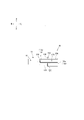
- connection terminal 20 has a pierce connection portion 21 at the right end and a barrel connection portion 22 at the left end (see FIGS. 2 and 3).
- the pierce connecting portion 21 is electrically connected to the flexible flat cable 2 by crimping the flexible flat cable 2 passed through the pierce (see FIG. 1).
- the barrel connecting portion 22 is electrically connected to the covered cable 3 by crimping the covered cable 3 inserted through the barrel (see FIG. 1).
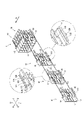
- the process of assembling the joint connector 4 for stacking the connector cases 10 containing the connection terminals 20 will be described with reference to FIG.
- the direction from the front side to the rear side of the joint connector 4 will be described as the stacking direction D. As shown in FIG.
- the connector cases 10 are stacked by pressing the engaging claws 122, 132 of one connector case 10 and the engaging grooves 124, 134 of the other connector case 10 in parallel with each other. It shows the process of In such a process, after the engaging claws 122 and 132 get over the edges of the stepped portions 123 and 133, the engaging claws 122 and 132 and the engaging grooves 124 and 134 are engaged with each other. be done.
- the connector cases 10 can be stacked without any deviation.
- the right side end faces of the engaging claws 122 and 132 and the right side end faces of the extensions 121 and 131 are equal, and the right side end faces of the engaging grooves 124 and 134 and the stepped portion 123 are the same.
- 133 are also the same, the right end faces of the extensions 121 and 131 and the right end faces of the stepped portions 123 and 133 are brought into contact with each other and pushed in, thereby making these connector cases 10 can be laminated without any deviation.
- the joint connector 4 is configured by stacking the connector cases 10 containing the connection terminals 20 .
- the connector case 10 has a main plate portion 11 that holds the connection terminals 20, and a pair of side plate portions (an upper side plate portion 12 and a lower side plate portion 13) perpendicular to the main plate portion 11 and parallel to each other.
- Engagement claws 122 and 132 projecting in a direction approaching the opposing side plate portions 12 and 13 are provided on the inner surfaces of the tip portions of the side plate portions 12 and 13, respectively.
- Engagement grooves 124 and 134 are provided on the outer surface of the base end portion of 13 so as to be recessed in a direction approaching the opposing side plate portions 12 and 13 .
- the engaging claws 122, 132 of one connector case 10 and the engaging grooves 124, 134 of the other connector case 10 are engaged with each other and stacked.
- the number of stacked connector cases 10 is not limited, and the number of terminals can be changed easily and freely. More specifically, in the joint connector 4 according to the present invention, engaging claws 122 projecting in a direction approaching the opposing side plate portions 12 and 13 are provided on the inner surfaces of the tip portions of the side plate portions 12 and 13, respectively. 132 are provided, and engagement grooves 124 and 134 are provided on the outer side surfaces of the proximal end portions of the side plate portions 12 and 13, respectively, and are recessed in a direction approaching the opposing side plate portions 12 and 13. As shown in FIG. The engaging claws 122 and 132 of one connector case 10 and the engaging grooves 124 and 134 of the other connector case 10 engage with each other and are stacked.
- another connector case 10 can be layered on the connector case 10 at the end of the connector cases 10 constituting the joint connector 4 . Further, by pressing the engaging claws 122, 132 of one connector case 10 and the engaging grooves 124, 134 of the other connector case 10 in parallel with each other, the connector cases 10 can be easily separated. Stacking becomes possible. Therefore, the number of stacked connector cases 10 is not limited, and the number of terminals can be easily and freely changed.
- engaging claws 122 and 132 are provided at the tip portions of the side plate portions 12 and 13, respectively, from the left side end surfaces 12a and 13a in the direction along the main plate portion 11 and the side plate portions 12 and 13 to the midway portion.
- Engagement grooves 124 and 134 are formed in the base end portions of the side plate portions 12 and 13, respectively, from the left side end surfaces 12a and 13a in the direction along the main plate portion 11 and the side plate portions 12 and 13. It is provided between the department. Then, when the right side end faces 12b, 13b of the engaging claws 122, 132 of one connector case 10 and the right side end faces 12c, 13c of the engaging grooves 124, 134 of the other connector case 10 are in contact with each other, Laminated.
- the right side end faces 12b, 13b of the engaging claws 122, 132 and the right side end faces 12c, 13c of the engaging grooves 124, 134 are brought into contact.
- These connector cases 10 can be stacked without deviation by pushing them in alignment with the contact positions.
- the engaging claws 122, 132 and the engaging grooves 124, 134 which are relatively long with respect to the length of one side of the side plate portions 12, 13 are provided, the engaging length by each other can be ensured. can be strongly laminated.
- the length of engagement between the connector cases 10 can be ensured, it is possible to suppress rattling of the stacked connector cases 10 .
- extension portions 121 and 131 having engaging claws 122 and 132 are provided at the tip portions of the side plate portions 12 and 13, respectively, on the left side in the direction along the main plate portion 11 and the side plate portions 12 and 13.
- Stepped portions 123, 133 having engaging grooves 124, 134 are provided between the end surfaces 12a, 13a and intermediate portions of the main plate portion 11 and the side plate portions 12, 12, 12, 13, at the base end portions of the respective side plate portions 12, 13. It is provided between left side end faces 12a and 13a in the direction along line 13 and an intermediate portion.
- the right side end faces 12b, 13b of the extensions 121, 131 of one connector case 10 and the right side end faces 12c, 13c of the stepped portions 123, 133 of the other connector case 10 are in contact with each other. be.
- the right side end faces 12b, 13b of the extension portions 121, 131 and the right side end faces 12c, 13c of the stepped portions 123, 133 are in contact with each other.
- These connector cases 10 can be stacked without any deviation by pressing them together.
- the extended portions 121, 131 and the stepped portions 123, 133 which are relatively long relative to the length of one side of the side plate portions 12, 13, are provided so that the mating length between them can be ensured. It becomes possible to laminate on Furthermore, since the mating length can be ensured, it is possible to suppress rattling of the stacked connector cases 10 .
- an inner plate 111 parallel to the side plates 12 and 13 is provided on the inner surface of the main plate 11
- an inner plate 111 parallel to the side plates 12 and 13 is provided on the outer surface of the main plate 11 .
- a vertical outer plate 113 is provided. Then, the left end surface of the inner plate 111 of one connector case 10 and the right flat surface of the outer plate 113 of the other connector case 10 are stacked in contact with each other.
- the left end surface of the inner plate 111 and the right flat surface of the outer plate 113 are aligned with the abutting positions and pushed in, so that these connectors can be stacked.
- the cases 10 can be stacked without any deviation.
- the inner plate 111 and the outer plate 113 are in vertical contact with the engaging claws 122, 132 and the engaging grooves 124, 134 that engage from the left side to the right side, the stacked connector cases 10 rattling can be suppressed.
- the engaging claws 122, 132 and the engaging grooves 124, 134 are provided along the left-right direction, there is a possibility that rattling may occur in the left-right direction.
- an inner engaging piece 112 projecting leftward is provided on the left end surface of the inner plate 111, and an inner engaging piece 112 projecting rightward is provided on the right plane of the outer plate 113.
- An outer engaging piece 114 is provided. Then, the inner engaging pieces 112 of one connector case 10 and the outer engaging pieces 114 of the other connector case 10 are stacked while being engaged with each other.
- the connector case 10 accommodates a plurality of connection terminals 20 parallel to the direction from the left side to the right side.
- a non-conductive inner plate 111 is arranged along the connection terminals 20 between two adjacent connection terminals 20 .
- the non-conductive inner plate 111 is arranged between two adjacent connection terminals 20 along the connection terminals 20, short-circuiting of the adjacent connection terminals 20 can occur. can be prevented.
- the inner plate 111 functions as a guide plate, which simplifies the work.
- widened portions 125, 135 are provided on the inner surfaces of the respective side plate portions 12, 13 and protrude in a direction approaching the opposing side plate portions 12, 13. Tip end surfaces 12d and 13d of the widened portions 125 and 135 are formed in parallel with the engaging claws 122 and 132 with a constant gap therebetween.
- the pushed-in main plate portion 11 comes into contact with the front end surfaces 12d and 13d of the widened portions 125 and 135 and is supported along the front end surfaces 12d and 13d. Therefore, these connector cases 10 can be stacked without tilting.
- projecting portions 126, 136 are provided on the outer surfaces of the side plate portions 12, 13, respectively, so as to project in a direction away from the opposing side plate portions 12, 13.
- the projecting portions 126 and 136 of the stacked connector cases 10 constitute guide passages for the band clamp 5 .
- the band clamp 5 can be used to bundle the stacked connector cases 10 . Also, the band clamp 5 can be used to fix the stacked connector cases 10 together to the fixing target.
- the object of the invention is a connector-equipped electric wire 1 having a joint connector 4 according to the present invention and electric wires (flexible flat cable 2 and covered cable 3) connected to connection terminals 20 of a connector case 10 constituting the joint connector 4. and
- the joint connector 4 in the present invention is a concept that includes all of the joint connectors 4 according to the inventions described above.
- connection terminal 20 According to such a connector-equipped wire 1, even if the specifications of the wire on one side (flexible flat cable 2) and the wire on the other side (coated cable 3) that are connected by the connection terminal 20 are different, they can be electrically connected. It can be configured as an electrical cable connected to the In such an electric cable, the electric wires 2 and 3 can be simply put together by preventing them from being separated or entangled.
- the electric wire on at least one side is the flexible flat cable 2 .
- the flexible flat cable 2 in the present invention is a concept that includes all cables in which conductors are arranged in parallel and sandwiched between sheet-like insulators.
- an electric wire 1 with a connector it is possible to construct an electric cable in which the flexible flat cable 2 and an electric wire (covered cable 3) of other specifications are electrically connected.
- the electric wires 2 and 3 can be simply put together by preventing them from being separated or entangled.
- the connector case 10 that houses the connection terminals 20 includes a main plate portion 11 that holds the connection terminals 20, and a pair of side plate portions (an upper side plate portion 12 and a lower side plate portion) that are perpendicular to the main plate portion 11 and parallel to each other. 13), and engaging claws 122 and 132 protruding in a direction approaching the opposing side plate portions 12 and 13 are provided on the inner surfaces of the tip portions of the side plate portions 12 and 13, respectively. It is characterized in that engaging grooves 124 and 134 that are recessed in a direction approaching the opposing side plate portions 12 and 13 are provided on the outer surfaces of the base end portions of the side plate portions 12 and 13, respectively. .
- the joint connector 4 configured by stacking the connector cases 10 can obtain the aforementioned effects. That is, the number of stacked connector cases 10 is not limited, and the number of terminals can be easily and freely changed.
- the electric wire with connector of the present invention corresponds to the electric wire with connector 1, and so on,
- the electric wire corresponds to the flexible flat cable 2 and the coated cable 3
- the joint connector corresponds to joint connector 4
- the connector case corresponds to the connector case 10
- the main plate portion corresponds to the main plate portion 11
- the side plate portion corresponds to the upper side plate portion 12 and the lower side plate portion 13
- the inner plate corresponds to the inner plate 111
- the inner engagement piece corresponds to the inner engagement piece 112
- the outer plate corresponds to the outer plate 113
- the outer engagement piece corresponds to the outer engagement piece 114
- the extensions correspond to extensions 121 and 131
- the engaging claws correspond to the engaging claws 122 and 132
- the stepped portion corresponds to the stepped portion 123 and the stepped portion 133
- the engagement groove corresponds to the engagement groove 124 and the engagement groove 134
- the widened portion corresponds to the widened portion 125 and the widened portion 135,
- the electric wire on one side electrically connected by the connection terminal 20 is the flexible flat cable 2, and the electric wire on the other side is the covered cable 3 having a circular cross section.
- the connection terminal 20 by changing the connection terminal 20, the flexible flat cable 2 may be connected to both.
- the coated cable 3 may be connected to both.
- the engaging claws 122, 132 of one connector case 10 and the engaging grooves 124, 134 of the other connector case 10 are arranged laterally (left and right). It is also possible to laminate the connector cases 10 by fitting them from the direction ) and sliding them. In this process, after the outer plate 113 rides over the long side of the inner plate 111, the left end surface of the inner plate 111 and the right flat surface of the outer plate 113 are brought into contact with each other, and the inner engaging piece 112 and the outer engaging piece 112 are engaged with each other. Since the joint piece 114 is engaged, a moderate feeling of moderation can be obtained.
- these connector cases 10 can be stacked without deviation.
- the right side end faces of the engaging claws 122 and 132 and the right side end faces of the extensions 121 and 131 are equal, and the right side end faces of the engaging grooves 124 and 134 and the stepped portion 123 are the same.
- 133 are also equal to each other, the right end faces of the extensions 121 and 131 and the right end faces of the stepped portions 123 and 133 abut and stop at appropriate positions. can be laminated without any deviation.
Abstract
Description
詳述すると、本願発明に係るジョイントコネクタにおいて、それぞれの側板部における先端部分の内側面には、対向する側板部に対して近接する方向に突出する係合爪又は離間する方向に陥没する係合溝が設けられ、それぞれの側板部における基端部分の外側面には、対向する側板部に対して近接する方向に陥没する係合溝又は離間する方向に突出する係合爪が設けられている。そして、一のコネクタケースにおける係合爪と他のコネクタケースにおける係合溝とが互いに係合して積層される。このため、ジョイントコネクタを構成するコネクタケースの最も末端にあるコネクタケースに対して別のコネクタケースを積層することができる。また、一のコネクタケースにおける係合爪と他のコネクタケースにおける係合溝とを平行に重ね合わせた状態で互いに対して押し込むことにより、これらコネクタケースを容易に積層することが可能となる。したがって、積層されるコネクタケースの個数について制限をなくし、ひいては端子数を容易かつ自在に変更できる。
なお、本発明におけるジョイントコネクタとは、前述した各発明に係るジョイントコネクタを全て包含した概念である。
なお、本発明におけるフレキシブルフラットケーブルとは、平行に並べた導電体をシート状の絶縁体で挟み込んだものを全て包含した概念である。
本願においては、全ての図面でジョイントコネクタ4の方向を示している。詳しくは矢印Fが前方側を示し、矢印Bが後方側を示し、矢印Rが右方側を示し、矢印Lが左方側を示している。そして、矢印Uが上方側を示し、矢印Dが下方側を示している。
詳述すると、本願発明に係るジョイントコネクタ4において、それぞれの側板部12,13における先端部分の内側面には、対向する側板部12,13に対して近接する方向に突出する係合爪122,132が設けられ、それぞれの側板部12,13における基端部分の外側面には、対向する側板部12,13に対して近接する方向に陥没する係合溝124,134が設けられている。そして、一のコネクタケース10における係合爪122,132と他のコネクタケース10における係合溝124,134とが互いに係合して積層される。このため、ジョイントコネクタ4を構成するコネクタケース10の最も末端にあるコネクタケース10に対して別のコネクタケース10を積層することができる。また、一のコネクタケース10における係合爪122,132と他のコネクタケース10における係合溝124,134とを平行に重ね合わせた状態で互いに対して押し込むことにより、これらコネクタケース10を容易に積層することが可能となる。したがって、積層されるコネクタケース10の個数について制限をなくし、ひいては端子数を容易かつ自在に変更できる。
なお、本発明におけるフレキシブルフラットケーブル2とは、平行に並べ導電体をシート状の絶縁体で挟み込んだものを全て包含した概念である。
以下同様に、
電線はフレキシブルフラットケーブル2及び被覆ケーブル3に対応し、
ジョイントコネクタはジョイントコネクタ4に対応し、
コネクタケースはコネクタケース10に対応し、
主板部は主板部11に対応し、
側板部は上方側板部12及び下方側板部13に対応し、
内側板は内側板111に対応し、
内側係合片は内側係合片112に対応し、
外側板は外側板113に対応し、
外側係合片は外側係合片114に対応し、
延長部は延長部121及び延長部131に対応し、
係合爪は係合爪122及び係合爪132に対応し、
段差部は段差部123及び段差部133に対応し、
係合溝は係合溝124及び係合溝134に対応し、
拡幅部は拡幅部125及び拡幅部135に対応し、
突出部は突出部126及び突出部136に対応し、
接続端子は接続端子20に対応し、
積層方向は積層方向Dに対応するも、この発明は、前述の実施形態の構成のみに限定されるものではなく、多くの実施形態を得ることができる。
2…フレキシブルフラットケーブル
3…被覆ケーブル
4…ジョイントコネクタ
10…コネクタケース
11…主板部
12…上方側板部
13…下方側板部
111…内側板
112…内側係合片
113…外側板
114…外側係合片
121…延長部
122…係合爪
123…段差部
124…係合溝
125…拡幅部
126…突出部
131…延長部
132…係合爪
133…段差部
134…係合溝
135…拡幅部
136…突出部
20…接続端子
D…積層方向
Claims (11)
- 接続端子を収容したコネクタケースを積層して構成されるジョイントコネクタであって、
前記コネクタケースは、前記接続端子を保持する主板部と、前記主板部に対して垂直かつ互いに対して平行となる一対の側板部とを有しており、
それぞれの前記側板部における先端部分の内側面には、対向する側板部に対して近接する方向に突出する係合爪又は離間する方向に陥没する係合溝が設けられ、
それぞれの前記側板部における基端部分の外側面には、対向する側板部に対して近接する方向に陥没する係合溝又は離間する方向に突出する係合爪が設けられ、
一の前記コネクタケースにおける前記係合爪と他の前記コネクタケースにおける前記係合溝とが互いに係合して積層された
ジョイントコネクタ。 - それぞれの前記側板部の先端部分には、前記係合爪又は前記係合溝が前記主板部ならびに前記側板部に沿う方向の一方側端面から中途部までの間に設けられ、
それぞれの前記側板部の基端部分には、前記係合溝又は前記係合爪が前記主板部ならびに前記側板部に沿う方向の一方側端面から中途部までの間に設けられ、
一の前記コネクタケースにおける前記係合爪の他方側端面と他の前記コネクタケースにおける前記係合溝の他方側端面とが当接した状態で積層された
請求項1に記載のジョイントコネクタ。 - それぞれの前記側板部の先端部分には、前記係合爪又は前記係合溝を有する延長部が前記主板部ならびに前記側板部に沿う方向の一方側端面から中途部までの間に設けられ、
それぞれの前記側板部の基端部分には、前記係合溝又は前記係合爪を有する段差部が前記主板部ならびに前記側板部に沿う方向の一方側端面から中途部までの間に設けられ、
一の前記コネクタケースにおける前記延長部の他方側端面と他の前記コネクタケースにおける前記段差部の他方側端面とが当接した状態で積層された
請求項1又は請求項2に記載のジョイントコネクタ。 - 前記主板部の内側面には、前記側板部に対して平行となる内側板が設けられ、前記主板部の外側面には、前記側板部に対して垂直となる外側板が設けられ、
一の前記コネクタケースにおける前記内側板の一方側端面と他の前記コネクタケースにおける前記外側板の他方側平面とが当接した状態で積層された
請求項1乃至請求項3のいずれかに記載のジョイントコネクタ。 - 前記内側板の一方側端面には、一方側に突出する内側係合片が設けられ、
前記外側板の他方側平面には、他方側に突出する外側係合片が設けられ、
一の前記コネクタケースにおける前記内側係合片と他の前記コネクタケースにおける前記外側係合片とが互いに係合した状態で積層された
請求項4に記載のジョイントコネクタ。 - 前記コネクタケースには、複数の接続端子が一方側から他方側に向かう方向に対して平行に収容されており、
非電導性である前記内側板が隣接する二つの前記接続端子の間で当該接続端子に沿って配置された
請求項4又は請求項5に記載のジョイントコネクタ。 - それぞれの前記側板部の内側面には、対向する側板部に対して近接する方向に突出する拡幅部が設けられており、
前記拡幅部の先端面が前記係合爪又は前記係合溝に対して平行かつ一定の間隔を隔てて対向する
請求項1乃至請求項6のいずれかに記載のジョイントコネクタ。 - それぞれの前記側板部の外側面には、対向する側板部に対して離間する方向に突出する突出部が設けられており、積層されたコネクタケースにおけるそれぞれの前記突出部がバンドクランプの案内通路を構成した
請求項1乃至請求項7のいずれかに記載のジョイントコネクタ。 - 請求項1乃至請求項8のいずれかに記載のジョイントコネクタと、
前記ジョイントコネクタを構成する前記コネクタケースの前記接続端子に接続された電線とを有している
コネクタ付電線。 - 少なくとも一方側の前記電線がフレキシブルフラットケーブルである
請求項9に記載のコネクタ付電線。 - 接続端子を収容するコネクタケースであって、
前記接続端子を保持する主板部と、前記主板部に対して垂直かつ互いに対して平行となる一対の側板部とを有しており、
それぞれの前記側板部における先端部分の内側面には、対向する側板部に対して近接する方向に突出する係合爪又は離間する方向に陥没する係合溝が設けられ、
それぞれの前記側板部における基端部分の外側面には、対向する側板部に対して近接する方向に陥没する係合溝又は離間する方向に突出する係合爪が設けられた
コネクタケース。
Priority Applications (5)
| Application Number | Priority Date | Filing Date | Title |
|---|---|---|---|
| JP2022564584A JP7214934B1 (ja) | 2021-03-23 | 2022-03-03 | ジョイントコネクタ、コネクタ付電線及びコネクタケース |
| CN202280022893.2A CN117044045A (zh) | 2021-03-23 | 2022-03-03 | 接头连接器、带连接器的电线以及连接器壳体 |
| EP22774979.3A EP4318824A1 (en) | 2021-03-23 | 2022-03-03 | Joint connector, connector-equipped electric wire, and connector case |
| KR1020237033242A KR20230150372A (ko) | 2021-03-23 | 2022-03-03 | 조인트 커넥터, 커넥터가 달린 전선 및 커넥터 케이스 |
| US18/469,612 US20240006801A1 (en) | 2021-03-23 | 2023-09-19 | Joint connector, connector-equipped wire, and connector case |
Applications Claiming Priority (2)
| Application Number | Priority Date | Filing Date | Title |
|---|---|---|---|
| JP2021-048749 | 2021-03-23 | ||
| JP2021048749 | 2021-03-23 |
Related Child Applications (1)
| Application Number | Title | Priority Date | Filing Date |
|---|---|---|---|
| US18/469,612 Continuation US20240006801A1 (en) | 2021-03-23 | 2023-09-19 | Joint connector, connector-equipped wire, and connector case |
Publications (1)
| Publication Number | Publication Date |
|---|---|
| WO2022202183A1 true WO2022202183A1 (ja) | 2022-09-29 |
Family
ID=83396939
Family Applications (1)
| Application Number | Title | Priority Date | Filing Date |
|---|---|---|---|
| PCT/JP2022/009073 WO2022202183A1 (ja) | 2021-03-23 | 2022-03-03 | ジョイントコネクタ、コネクタ付電線及びコネクタケース |
Country Status (6)
| Country | Link |
|---|---|
| US (1) | US20240006801A1 (ja) |
| EP (1) | EP4318824A1 (ja) |
| JP (1) | JP7214934B1 (ja) |
| KR (1) | KR20230150372A (ja) |
| CN (1) | CN117044045A (ja) |
| WO (1) | WO2022202183A1 (ja) |
Citations (7)
| Publication number | Priority date | Publication date | Assignee | Title |
|---|---|---|---|---|
| JPH02148583A (ja) * | 1988-11-29 | 1990-06-07 | Yazaki Corp | 多段式コネクタ |
| JP2000150055A (ja) * | 1998-11-13 | 2000-05-30 | Yazaki Corp | ジョイントコネクタ |
| JP2002359042A (ja) * | 2001-03-30 | 2002-12-13 | Sumitomo Wiring Syst Ltd | ジョイントコネクタ |
| JP2009064735A (ja) | 2007-09-07 | 2009-03-26 | Furukawa Electric Co Ltd:The | コネクタ及びそのサブハウジングの色設定方法 |
| JP2014112497A (ja) | 2012-12-05 | 2014-06-19 | Furukawa Electric Co Ltd:The | ジョイントコネクタ |
| WO2015068392A1 (ja) * | 2013-11-06 | 2015-05-14 | 古河電気工業株式会社 | 接続端子及び電線アッセンブリ |
| JP2017027810A (ja) * | 2015-07-23 | 2017-02-02 | 矢崎総業株式会社 | 積層タイプコネクタのガタ詰め構造 |
-
2022
- 2022-03-03 WO PCT/JP2022/009073 patent/WO2022202183A1/ja active Application Filing
- 2022-03-03 KR KR1020237033242A patent/KR20230150372A/ko unknown
- 2022-03-03 CN CN202280022893.2A patent/CN117044045A/zh active Pending
- 2022-03-03 EP EP22774979.3A patent/EP4318824A1/en active Pending
- 2022-03-03 JP JP2022564584A patent/JP7214934B1/ja active Active
-
2023
- 2023-09-19 US US18/469,612 patent/US20240006801A1/en active Pending
Patent Citations (7)
| Publication number | Priority date | Publication date | Assignee | Title |
|---|---|---|---|---|
| JPH02148583A (ja) * | 1988-11-29 | 1990-06-07 | Yazaki Corp | 多段式コネクタ |
| JP2000150055A (ja) * | 1998-11-13 | 2000-05-30 | Yazaki Corp | ジョイントコネクタ |
| JP2002359042A (ja) * | 2001-03-30 | 2002-12-13 | Sumitomo Wiring Syst Ltd | ジョイントコネクタ |
| JP2009064735A (ja) | 2007-09-07 | 2009-03-26 | Furukawa Electric Co Ltd:The | コネクタ及びそのサブハウジングの色設定方法 |
| JP2014112497A (ja) | 2012-12-05 | 2014-06-19 | Furukawa Electric Co Ltd:The | ジョイントコネクタ |
| WO2015068392A1 (ja) * | 2013-11-06 | 2015-05-14 | 古河電気工業株式会社 | 接続端子及び電線アッセンブリ |
| JP2017027810A (ja) * | 2015-07-23 | 2017-02-02 | 矢崎総業株式会社 | 積層タイプコネクタのガタ詰め構造 |
Also Published As
| Publication number | Publication date |
|---|---|
| US20240006801A1 (en) | 2024-01-04 |
| JPWO2022202183A1 (ja) | 2022-09-29 |
| EP4318824A1 (en) | 2024-02-07 |
| JP7214934B1 (ja) | 2023-01-30 |
| CN117044045A (zh) | 2023-11-10 |
| KR20230150372A (ko) | 2023-10-30 |
Similar Documents
| Publication | Publication Date | Title |
|---|---|---|
| WO2017057215A1 (ja) | 電池間接続装置及び電池間接続装置組立体 | |
| WO2019142442A1 (ja) | コネクタ | |
| JP2013232324A (ja) | コネクタ | |
| JP6669996B2 (ja) | コネクタ | |
| WO2022202183A1 (ja) | ジョイントコネクタ、コネクタ付電線及びコネクタケース | |
| JP2019128996A5 (ja) | ||
| JPWO2022202183A5 (ja) | ||
| JP6768304B2 (ja) | コネクタの組立方法 | |
| JP6955228B2 (ja) | コネクタ | |
| JP6617545B2 (ja) | コネクタ | |
| CN212392406U (zh) | 电连接器 | |
| WO2023042619A1 (ja) | 積層コネクタ | |
| JP6974805B2 (ja) | コネクタ | |
| WO2023042620A1 (ja) | 端子金具の接続構造及びジョイントコネクタ | |
| WO2010087473A1 (ja) | 中継コネクタ | |
| JP5566730B2 (ja) | 圧接コネクタ及びワイヤハーネスの製造方法 | |
| JP6228004B2 (ja) | コネクタ | |
| JP2023170120A (ja) | コネクタ及びコネクタ付きワイヤハーネス | |
| JP4494197B2 (ja) | 合体コネクタ | |
| JP2022142875A (ja) | ケーブルコネクタ及びその組立て方法 | |
| JP4977731B2 (ja) | コネクタのハウジング | |
| JP2001143804A (ja) | 端子金具 | |
| JP2019046699A (ja) | コネクタハウジングおよびコネクタ | |
| TW202034591A (zh) | 電連接器及電連接器組合 | |
| JPH0676868A (ja) | ばら線用圧接コネクタ |
Legal Events
| Date | Code | Title | Description |
|---|---|---|---|
| ENP | Entry into the national phase |
Ref document number: 2022564584 Country of ref document: JP Kind code of ref document: A |
|
| 121 | Ep: the epo has been informed by wipo that ep was designated in this application |
Ref document number: 22774979 Country of ref document: EP Kind code of ref document: A1 |
|
| WWE | Wipo information: entry into national phase |
Ref document number: 202280022893.2 Country of ref document: CN |
|
| ENP | Entry into the national phase |
Ref document number: 20237033242 Country of ref document: KR Kind code of ref document: A |
|
| WWE | Wipo information: entry into national phase |
Ref document number: 2022774979 Country of ref document: EP |
|
| NENP | Non-entry into the national phase |
Ref country code: DE |
|
| ENP | Entry into the national phase |
Ref document number: 2022774979 Country of ref document: EP Effective date: 20231023 |