JP7214934B1 - ジョイントコネクタ、コネクタ付電線及びコネクタケース - Google Patents
ジョイントコネクタ、コネクタ付電線及びコネクタケース Download PDFInfo
- Publication number
- JP7214934B1 JP7214934B1 JP2022564584A JP2022564584A JP7214934B1 JP 7214934 B1 JP7214934 B1 JP 7214934B1 JP 2022564584 A JP2022564584 A JP 2022564584A JP 2022564584 A JP2022564584 A JP 2022564584A JP 7214934 B1 JP7214934 B1 JP 7214934B1
- Authority
- JP
- Japan
- Prior art keywords
- connector
- side plate
- plate portion
- engaging
- portions
- Prior art date
- Legal status (The legal status is an assumption and is not a legal conclusion. Google has not performed a legal analysis and makes no representation as to the accuracy of the status listed.)
- Active
Links
- 210000000078 claw Anatomy 0.000 claims abstract description 67
- 238000000034 method Methods 0.000 description 4
- 239000004020 conductor Substances 0.000 description 3
- 230000013011 mating Effects 0.000 description 3
- 238000002788 crimping Methods 0.000 description 2
- 230000000694 effects Effects 0.000 description 2
- 239000012212 insulator Substances 0.000 description 2
- 238000005452 bending Methods 0.000 description 1
- 238000010586 diagram Methods 0.000 description 1
- 230000001105 regulatory effect Effects 0.000 description 1
- 229920003002 synthetic resin Polymers 0.000 description 1
- 239000000057 synthetic resin Substances 0.000 description 1
Images


Classifications
-
- H—ELECTRICITY
- H01—ELECTRIC ELEMENTS
- H01R—ELECTRICALLY-CONDUCTIVE CONNECTIONS; STRUCTURAL ASSOCIATIONS OF A PLURALITY OF MUTUALLY-INSULATED ELECTRICAL CONNECTING ELEMENTS; COUPLING DEVICES; CURRENT COLLECTORS
- H01R13/00—Details of coupling devices of the kinds covered by groups H01R12/70 or H01R24/00 - H01R33/00
- H01R13/46—Bases; Cases
- H01R13/514—Bases; Cases composed as a modular blocks or assembly, i.e. composed of co-operating parts provided with contact members or holding contact members between them
-
- H—ELECTRICITY
- H01—ELECTRIC ELEMENTS
- H01R—ELECTRICALLY-CONDUCTIVE CONNECTIONS; STRUCTURAL ASSOCIATIONS OF A PLURALITY OF MUTUALLY-INSULATED ELECTRICAL CONNECTING ELEMENTS; COUPLING DEVICES; CURRENT COLLECTORS
- H01R13/00—Details of coupling devices of the kinds covered by groups H01R12/70 or H01R24/00 - H01R33/00
- H01R13/46—Bases; Cases
- H01R13/502—Bases; Cases composed of different pieces
- H01R13/508—Bases; Cases composed of different pieces assembled by a separate clip or spring
-
- H—ELECTRICITY
- H01—ELECTRIC ELEMENTS
- H01R—ELECTRICALLY-CONDUCTIVE CONNECTIONS; STRUCTURAL ASSOCIATIONS OF A PLURALITY OF MUTUALLY-INSULATED ELECTRICAL CONNECTING ELEMENTS; COUPLING DEVICES; CURRENT COLLECTORS
- H01R31/00—Coupling parts supported only by co-operation with counterpart
- H01R31/08—Short-circuiting members for bridging contacts in a counterpart
-
- H—ELECTRICITY
- H01—ELECTRIC ELEMENTS
- H01R—ELECTRICALLY-CONDUCTIVE CONNECTIONS; STRUCTURAL ASSOCIATIONS OF A PLURALITY OF MUTUALLY-INSULATED ELECTRICAL CONNECTING ELEMENTS; COUPLING DEVICES; CURRENT COLLECTORS
- H01R11/00—Individual connecting elements providing two or more spaced connecting locations for conductive members which are, or may be, thereby interconnected, e.g. end pieces for wires or cables supported by the wire or cable and having means for facilitating electrical connection to some other wire, terminal, or conductive member, blocks of binding posts
- H01R11/03—Individual connecting elements providing two or more spaced connecting locations for conductive members which are, or may be, thereby interconnected, e.g. end pieces for wires or cables supported by the wire or cable and having means for facilitating electrical connection to some other wire, terminal, or conductive member, blocks of binding posts characterised by the relationship between the connecting locations
- H01R11/05—Individual connecting elements providing two or more spaced connecting locations for conductive members which are, or may be, thereby interconnected, e.g. end pieces for wires or cables supported by the wire or cable and having means for facilitating electrical connection to some other wire, terminal, or conductive member, blocks of binding posts characterised by the relationship between the connecting locations the connecting locations having different types of direct connections
-
- H—ELECTRICITY
- H01—ELECTRIC ELEMENTS
- H01R—ELECTRICALLY-CONDUCTIVE CONNECTIONS; STRUCTURAL ASSOCIATIONS OF A PLURALITY OF MUTUALLY-INSULATED ELECTRICAL CONNECTING ELEMENTS; COUPLING DEVICES; CURRENT COLLECTORS
- H01R12/00—Structural associations of a plurality of mutually-insulated electrical connecting elements, specially adapted for printed circuits, e.g. printed circuit boards [PCB], flat or ribbon cables, or like generally planar structures, e.g. terminal strips, terminal blocks; Coupling devices specially adapted for printed circuits, flat or ribbon cables, or like generally planar structures; Terminals specially adapted for contact with, or insertion into, printed circuits, flat or ribbon cables, or like generally planar structures
- H01R12/50—Fixed connections
- H01R12/59—Fixed connections for flexible printed circuits, flat or ribbon cables or like structures
- H01R12/63—Fixed connections for flexible printed circuits, flat or ribbon cables or like structures connecting to another shape cable
-
- H—ELECTRICITY
- H01—ELECTRIC ELEMENTS
- H01R—ELECTRICALLY-CONDUCTIVE CONNECTIONS; STRUCTURAL ASSOCIATIONS OF A PLURALITY OF MUTUALLY-INSULATED ELECTRICAL CONNECTING ELEMENTS; COUPLING DEVICES; CURRENT COLLECTORS
- H01R12/00—Structural associations of a plurality of mutually-insulated electrical connecting elements, specially adapted for printed circuits, e.g. printed circuit boards [PCB], flat or ribbon cables, or like generally planar structures, e.g. terminal strips, terminal blocks; Coupling devices specially adapted for printed circuits, flat or ribbon cables, or like generally planar structures; Terminals specially adapted for contact with, or insertion into, printed circuits, flat or ribbon cables, or like generally planar structures
- H01R12/50—Fixed connections
- H01R12/59—Fixed connections for flexible printed circuits, flat or ribbon cables or like structures
- H01R12/65—Fixed connections for flexible printed circuits, flat or ribbon cables or like structures characterised by the terminal
- H01R12/69—Fixed connections for flexible printed circuits, flat or ribbon cables or like structures characterised by the terminal deformable terminals, e.g. crimping terminals
-
- H—ELECTRICITY
- H01—ELECTRIC ELEMENTS
- H01R—ELECTRICALLY-CONDUCTIVE CONNECTIONS; STRUCTURAL ASSOCIATIONS OF A PLURALITY OF MUTUALLY-INSULATED ELECTRICAL CONNECTING ELEMENTS; COUPLING DEVICES; CURRENT COLLECTORS
- H01R12/00—Structural associations of a plurality of mutually-insulated electrical connecting elements, specially adapted for printed circuits, e.g. printed circuit boards [PCB], flat or ribbon cables, or like generally planar structures, e.g. terminal strips, terminal blocks; Coupling devices specially adapted for printed circuits, flat or ribbon cables, or like generally planar structures; Terminals specially adapted for contact with, or insertion into, printed circuits, flat or ribbon cables, or like generally planar structures
- H01R12/70—Coupling devices
- H01R12/77—Coupling devices for flexible printed circuits, flat or ribbon cables or like structures
- H01R12/771—Details
-
- H—ELECTRICITY
- H01—ELECTRIC ELEMENTS
- H01R—ELECTRICALLY-CONDUCTIVE CONNECTIONS; STRUCTURAL ASSOCIATIONS OF A PLURALITY OF MUTUALLY-INSULATED ELECTRICAL CONNECTING ELEMENTS; COUPLING DEVICES; CURRENT COLLECTORS
- H01R4/00—Electrically-conductive connections between two or more conductive members in direct contact, i.e. touching one another; Means for effecting or maintaining such contact; Electrically-conductive connections having two or more spaced connecting locations for conductors and using contact members penetrating insulation
- H01R4/10—Electrically-conductive connections between two or more conductive members in direct contact, i.e. touching one another; Means for effecting or maintaining such contact; Electrically-conductive connections having two or more spaced connecting locations for conductors and using contact members penetrating insulation effected solely by twisting, wrapping, bending, crimping, or other permanent deformation
- H01R4/18—Electrically-conductive connections between two or more conductive members in direct contact, i.e. touching one another; Means for effecting or maintaining such contact; Electrically-conductive connections having two or more spaced connecting locations for conductors and using contact members penetrating insulation effected solely by twisting, wrapping, bending, crimping, or other permanent deformation by crimping
- H01R4/183—Electrically-conductive connections between two or more conductive members in direct contact, i.e. touching one another; Means for effecting or maintaining such contact; Electrically-conductive connections having two or more spaced connecting locations for conductors and using contact members penetrating insulation effected solely by twisting, wrapping, bending, crimping, or other permanent deformation by crimping for cylindrical elongated bodies, e.g. cables having circular cross-section
Abstract
Description
詳述すると、本願発明に係るジョイントコネクタにおいて、それぞれの側板部における先端部分の内側面には、対向する側板部に対して近接する方向に突出する係合爪又は離間する方向に陥没する係合溝が設けられ、それぞれの側板部における基端部分の外側面には、対向する側板部に対して近接する方向に陥没する係合溝又は離間する方向に突出する係合爪が設けられている。そして、一のコネクタケースにおける係合爪と他のコネクタケースにおける係合溝とが互いに係合して積層される。このため、ジョイントコネクタを構成するコネクタケースの最も末端にあるコネクタケースに対して別のコネクタケースを積層することができる。また、一のコネクタケースにおける係合爪と他のコネクタケースにおける係合溝とを平行に重ね合わせた状態で互いに対して押し込むことにより、これらコネクタケースを容易に積層することが可能となる。したがって、積層されるコネクタケースの個数について制限をなくし、ひいては端子数を容易かつ自在に変更できる。
なお、本発明におけるジョイントコネクタとは、前述した各発明に係るジョイントコネクタを全て包含した概念である。
なお、本発明におけるフレキシブルフラットケーブルとは、平行に並べた導電体をシート状の絶縁体で挟み込んだものを全て包含した概念である。
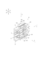
本願においては、全ての図面でジョイントコネクタ4の方向を示している。詳しくは矢印Fが前方側を示し、矢印Bが後方側を示し、矢印Rが右方側を示し、矢印Lが左方側を示している。そして、矢印Uが上方側を示し、矢印Dが下方側を示している。
詳述すると、本願発明に係るジョイントコネクタ4において、それぞれの側板部12,13における先端部分の内側面には、対向する側板部12,13に対して近接する方向に突出する係合爪122,132が設けられ、それぞれの側板部12,13における基端部分の外側面には、対向する側板部12,13に対して近接する方向に陥没する係合溝124,134が設けられている。そして、一のコネクタケース10における係合爪122,132と他のコネクタケース10における係合溝124,134とが互いに係合して積層される。このため、ジョイントコネクタ4を構成するコネクタケース10の最も末端にあるコネクタケース10に対して別のコネクタケース10を積層することができる。また、一のコネクタケース10における係合爪122,132と他のコネクタケース10における係合溝124,134とを平行に重ね合わせた状態で互いに対して押し込むことにより、これらコネクタケース10を容易に積層することが可能となる。したがって、積層されるコネクタケース10の個数について制限をなくし、ひいては端子数を容易かつ自在に変更できる。
なお、本発明におけるフレキシブルフラットケーブル2とは、平行に並べ導電体をシート状の絶縁体で挟み込んだものを全て包含した概念である。
以下同様に、
電線はフレキシブルフラットケーブル2及び被覆ケーブル3に対応し、
ジョイントコネクタはジョイントコネクタ4に対応し、
コネクタケースはコネクタケース10に対応し、
主板部は主板部11に対応し、
側板部は上方側板部12及び下方側板部13に対応し、
内側板は内側板111に対応し、
内側係合片は内側係合片112に対応し、
外側板は外側板113に対応し、
外側係合片は外側係合片114に対応し、
延長部は延長部121及び延長部131に対応し、
係合爪は係合爪122及び係合爪132に対応し、
段差部は段差部123及び段差部133に対応し、
係合溝は係合溝124及び係合溝134に対応し、
拡幅部は拡幅部125及び拡幅部135に対応し、
突出部は突出部126及び突出部136に対応し、
接続端子は接続端子20に対応し、
積層方向は積層方向Dに対応するも、この発明は、前述の実施形態の構成のみに限定されるものではなく、多くの実施形態を得ることができる。
2…フレキシブルフラットケーブル
3…被覆ケーブル
4…ジョイントコネクタ
10…コネクタケース
11…主板部
12…上方側板部
13…下方側板部
111…内側板
112…内側係合片
113…外側板
114…外側係合片
121…延長部
122…係合爪
123…段差部
124…係合溝
125…拡幅部
126…突出部
131…延長部
132…係合爪
133…段差部
134…係合溝
135…拡幅部
136…突出部
20…接続端子
D…積層方向
Claims (9)
- 接続端子を収容したコネクタケースを積層して構成されるジョイントコネクタであって、
前記コネクタケースは、前記接続端子を保持する主板部と、前記主板部に対して垂直かつ互いに対して平行となる一対の側板部とを有しており、
それぞれの前記側板部における先端部分の内側面には、対向する側板部に対して近接する方向に突出する係合爪又は離間する方向に陥没する係合溝が設けられ、
それぞれの前記側板部における基端部分の外側面には、対向する側板部に対して近接する方向に陥没する係合溝又は離間する方向に突出する係合爪が設けられ、
一の前記コネクタケースにおける前記係合爪と他の前記コネクタケースにおける前記係合溝とが互いに係合して積層され、
前記主板部の内側面には、前記側板部に対して平行となる内側板が設けられ、前記主板部の外側面には、前記側板部に対して垂直となる外側板が設けられ、
一の前記コネクタケースにおける前記内側板の一方側端面と他の前記コネクタケースにおける前記外側板の他方側平面とが当接した状態で積層され、
前記内側板の一方側端面には、一方側に突出する内側係合片が設けられ、
前記外側板の他方側平面には、他方側に突出する外側係合片が設けられ、
一の前記コネクタケースにおける前記内側係合片と他の前記コネクタケースにおける前記外側係合片とが互いに係合した状態で積層された
ジョイントコネクタ。 - それぞれの前記側板部の先端部分には、前記係合爪又は前記係合溝が前記主板部ならびに前記側板部に沿う方向の一方側端面から中途部までの間に設けられ、
それぞれの前記側板部の基端部分には、前記係合溝又は前記係合爪が前記主板部ならびに前記側板部に沿う方向の一方側端面から中途部までの間に設けられ、
一の前記コネクタケースにおける前記係合爪の他方側端面と他の前記コネクタケースにおける前記係合溝の他方側端面とが当接した状態で積層された
請求項1に記載のジョイントコネクタ。 - それぞれの前記側板部の先端部分には、前記係合爪又は前記係合溝を有する延長部が前記主板部ならびに前記側板部に沿う方向の一方側端面から中途部までの間に設けられ、
それぞれの前記側板部の基端部分には、前記係合溝又は前記係合爪を有する段差部が前記主板部ならびに前記側板部に沿う方向の一方側端面から中途部までの間に設けられ、
一の前記コネクタケースにおける前記延長部の他方側端面と他の前記コネクタケースにおける前記段差部の他方側端面とが当接した状態で積層された
請求項1又は請求項2に記載のジョイントコネクタ。 - 前記コネクタケースには、複数の接続端子が一方側から他方側に向かう方向に対して平行に収容されており、
非電導性である前記内側板が隣接する二つの前記接続端子の間で当該接続端子に沿って配置された
請求項1乃至請求項3のいずれかに記載のジョイントコネクタ。 - それぞれの前記側板部の内側面には、対向する側板部に対して近接する方向に突出する拡幅部が設けられており、
前記拡幅部の先端面が前記係合爪又は前記係合溝に対して平行かつ一定の間隔を隔てて対向する
請求項1乃至請求項4のいずれかに記載のジョイントコネクタ。 - それぞれの前記側板部の外側面には、対向する側板部に対して離間する方向に突出する突出部が設けられており、積層されたコネクタケースにおけるそれぞれの前記突出部がバンドクランプの案内通路を構成した
請求項1乃至請求項5のいずれかに記載のジョイントコネクタ。 - 請求項1乃至請求項6のいずれかに記載のジョイントコネクタと、
前記ジョイントコネクタを構成する前記コネクタケースの前記接続端子に接続された電線とを有している
コネクタ付電線。 - 少なくとも一方側の前記電線がフレキシブルフラットケーブルである
請求項7に記載のコネクタ付電線。 - 接続端子を収容するコネクタケースであって、
前記接続端子を保持する主板部と、前記主板部に対して垂直かつ互いに対して平行となる一対の側板部とを有しており、
それぞれの前記側板部における先端部分の内側面には、対向する側板部に対して近接する方向に突出する係合爪又は離間する方向に陥没する係合溝が設けられ、
それぞれの前記側板部における基端部分の外側面には、対向する側板部に対して近接する方向に陥没する係合溝又は離間する方向に突出する係合爪が設けられ、
前記主板部の内側面には、前記側板部に対して平行となる内側板が設けられ、前記主板部の外側面には、前記側板部に対して垂直となる外側板が設けられ、
一の前記コネクタケースにおける前記内側板の一方側端面と他の前記コネクタケースにおける前記外側板の他方側平面とが当接した状態で積層され、
前記内側板の一方側端面には、一方側に突出する内側係合片が設けられ、
前記外側板の他方側平面には、他方側に突出する外側係合片が設けられ、
一の前記コネクタケースにおける前記内側係合片と他の前記コネクタケースにおける前記外側係合片とが互いに係合した状態で積層された
コネクタケース。
Applications Claiming Priority (3)
| Application Number | Priority Date | Filing Date | Title |
|---|---|---|---|
| JP2021048749 | 2021-03-23 | ||
| JP2021048749 | 2021-03-23 | ||
| PCT/JP2022/009073 WO2022202183A1 (ja) | 2021-03-23 | 2022-03-03 | ジョイントコネクタ、コネクタ付電線及びコネクタケース |
Publications (3)
| Publication Number | Publication Date |
|---|---|
| JPWO2022202183A1 JPWO2022202183A1 (ja) | 2022-09-29 |
| JP7214934B1 true JP7214934B1 (ja) | 2023-01-30 |
| JPWO2022202183A5 JPWO2022202183A5 (ja) | 2023-02-21 |
Family
ID=83396939
Family Applications (1)
| Application Number | Title | Priority Date | Filing Date |
|---|---|---|---|
| JP2022564584A Active JP7214934B1 (ja) | 2021-03-23 | 2022-03-03 | ジョイントコネクタ、コネクタ付電線及びコネクタケース |
Country Status (6)
| Country | Link |
|---|---|
| US (1) | US20240006801A1 (ja) |
| EP (1) | EP4318824A1 (ja) |
| JP (1) | JP7214934B1 (ja) |
| KR (1) | KR20230150372A (ja) |
| CN (1) | CN117044045A (ja) |
| WO (1) | WO2022202183A1 (ja) |
Citations (5)
| Publication number | Priority date | Publication date | Assignee | Title |
|---|---|---|---|---|
| JPH02148583A (ja) * | 1988-11-29 | 1990-06-07 | Yazaki Corp | 多段式コネクタ |
| JP2000150055A (ja) * | 1998-11-13 | 2000-05-30 | Yazaki Corp | ジョイントコネクタ |
| JP2002359042A (ja) * | 2001-03-30 | 2002-12-13 | Sumitomo Wiring Syst Ltd | ジョイントコネクタ |
| WO2015068392A1 (ja) * | 2013-11-06 | 2015-05-14 | 古河電気工業株式会社 | 接続端子及び電線アッセンブリ |
| JP2017027810A (ja) * | 2015-07-23 | 2017-02-02 | 矢崎総業株式会社 | 積層タイプコネクタのガタ詰め構造 |
Family Cites Families (2)
| Publication number | Priority date | Publication date | Assignee | Title |
|---|---|---|---|---|
| JP4809818B2 (ja) | 2007-09-07 | 2011-11-09 | 古河電気工業株式会社 | コネクタ |
| JP5730842B2 (ja) | 2012-12-05 | 2015-06-10 | 古河電気工業株式会社 | ジョイントコネクタ |
-
2022
- 2022-03-03 JP JP2022564584A patent/JP7214934B1/ja active Active
- 2022-03-03 KR KR1020237033242A patent/KR20230150372A/ko unknown
- 2022-03-03 CN CN202280022893.2A patent/CN117044045A/zh active Pending
- 2022-03-03 WO PCT/JP2022/009073 patent/WO2022202183A1/ja active Application Filing
- 2022-03-03 EP EP22774979.3A patent/EP4318824A1/en active Pending
-
2023
- 2023-09-19 US US18/469,612 patent/US20240006801A1/en active Pending
Patent Citations (5)
| Publication number | Priority date | Publication date | Assignee | Title |
|---|---|---|---|---|
| JPH02148583A (ja) * | 1988-11-29 | 1990-06-07 | Yazaki Corp | 多段式コネクタ |
| JP2000150055A (ja) * | 1998-11-13 | 2000-05-30 | Yazaki Corp | ジョイントコネクタ |
| JP2002359042A (ja) * | 2001-03-30 | 2002-12-13 | Sumitomo Wiring Syst Ltd | ジョイントコネクタ |
| WO2015068392A1 (ja) * | 2013-11-06 | 2015-05-14 | 古河電気工業株式会社 | 接続端子及び電線アッセンブリ |
| JP2017027810A (ja) * | 2015-07-23 | 2017-02-02 | 矢崎総業株式会社 | 積層タイプコネクタのガタ詰め構造 |
Also Published As
| Publication number | Publication date |
|---|---|
| JPWO2022202183A1 (ja) | 2022-09-29 |
| US20240006801A1 (en) | 2024-01-04 |
| KR20230150372A (ko) | 2023-10-30 |
| WO2022202183A1 (ja) | 2022-09-29 |
| CN117044045A (zh) | 2023-11-10 |
| EP4318824A1 (en) | 2024-02-07 |
Similar Documents
| Publication | Publication Date | Title |
|---|---|---|
| JP5682997B2 (ja) | 電気コネクタ | |
| WO2017057215A1 (ja) | 電池間接続装置及び電池間接続装置組立体 | |
| US20170104288A1 (en) | Conductive terminal and electrical connector assembly | |
| JP2019128997A (ja) | コネクタ | |
| JP6669996B2 (ja) | コネクタ | |
| JP7214934B1 (ja) | ジョイントコネクタ、コネクタ付電線及びコネクタケース | |
| JP2019128996A5 (ja) | ||
| JPWO2022202183A5 (ja) | ||
| JP6768304B2 (ja) | コネクタの組立方法 | |
| WO2018173687A1 (ja) | コネクタ | |
| CN212392406U (zh) | 电连接器 | |
| JP5769552B2 (ja) | コネクタ | |
| JP6617545B2 (ja) | コネクタ | |
| JP2022104906A (ja) | 端子本体、接続端子および端子本体製造用シート材 | |
| JP2020080325A (ja) | コネクタ | |
| JP2022076147A (ja) | コネクタ | |
| WO2023042619A1 (ja) | 積層コネクタ | |
| WO2023042620A1 (ja) | 端子金具の接続構造及びジョイントコネクタ | |
| JP2023170120A (ja) | コネクタ及びコネクタ付きワイヤハーネス | |
| JP7351687B2 (ja) | コネクタ | |
| JP6228004B2 (ja) | コネクタ | |
| JP2022142875A (ja) | ケーブルコネクタ及びその組立て方法 | |
| JP4494197B2 (ja) | 合体コネクタ | |
| WO2010087473A1 (ja) | 中継コネクタ | |
| JP5566730B2 (ja) | 圧接コネクタ及びワイヤハーネスの製造方法 |
Legal Events
| Date | Code | Title | Description |
|---|---|---|---|
| A521 | Request for written amendment filed |
Free format text: JAPANESE INTERMEDIATE CODE: A523 Effective date: 20221024 |
|
| A621 | Written request for application examination |
Free format text: JAPANESE INTERMEDIATE CODE: A621 Effective date: 20221024 |
|
| A871 | Explanation of circumstances concerning accelerated examination |
Free format text: JAPANESE INTERMEDIATE CODE: A871 Effective date: 20221024 |
|
| TRDD | Decision of grant or rejection written | ||
| A01 | Written decision to grant a patent or to grant a registration (utility model) |
Free format text: JAPANESE INTERMEDIATE CODE: A01 Effective date: 20230110 |
|
| A61 | First payment of annual fees (during grant procedure) |
Free format text: JAPANESE INTERMEDIATE CODE: A61 Effective date: 20230118 |
|
| R151 | Written notification of patent or utility model registration |
Ref document number: 7214934 Country of ref document: JP Free format text: JAPANESE INTERMEDIATE CODE: R151 |