WO2019130774A1 - 電池管理装置、電池システム、及び車両用電源システム - Google Patents
電池管理装置、電池システム、及び車両用電源システム Download PDFInfo
- Publication number
- WO2019130774A1 WO2019130774A1 PCT/JP2018/039700 JP2018039700W WO2019130774A1 WO 2019130774 A1 WO2019130774 A1 WO 2019130774A1 JP 2018039700 W JP2018039700 W JP 2018039700W WO 2019130774 A1 WO2019130774 A1 WO 2019130774A1
- Authority
- WO
- WIPO (PCT)
- Prior art keywords
- secondary battery
- battery
- discharge
- management device
- stage
- Prior art date
- Legal status (The legal status is an assumption and is not a legal conclusion. Google has not performed a legal analysis and makes no representation as to the accuracy of the status listed.)
- Ceased
Links
Images


Classifications
-
- H—ELECTRICITY
- H01—ELECTRIC ELEMENTS
- H01M—PROCESSES OR MEANS, e.g. BATTERIES, FOR THE DIRECT CONVERSION OF CHEMICAL ENERGY INTO ELECTRICAL ENERGY
- H01M10/00—Secondary cells; Manufacture thereof
- H01M10/42—Methods or arrangements for servicing or maintenance of secondary cells or secondary half-cells
- H01M10/48—Accumulators combined with arrangements for measuring, testing or indicating the condition of cells, e.g. the level or density of the electrolyte
- H01M10/486—Accumulators combined with arrangements for measuring, testing or indicating the condition of cells, e.g. the level or density of the electrolyte for measuring temperature
-
- H—ELECTRICITY
- H02—GENERATION; CONVERSION OR DISTRIBUTION OF ELECTRIC POWER
- H02J—ELECTRIC POWER NETWORKS; CIRCUIT ARRANGEMENTS OR SYSTEMS FOR SUPPLYING OR DISTRIBUTING ELECTRIC POWER; SYSTEMS FOR STORING ELECTRIC ENERGY
- H02J7/00—Circuit arrangements for charging or discharging batteries or for supplying loads from batteries
- H02J7/80—Circuit arrangements for charging or discharging batteries or for supplying loads from batteries including monitoring or indicating arrangements
- H02J7/82—Control of state of charge [SOC]
-
- B—PERFORMING OPERATIONS; TRANSPORTING
- B60—VEHICLES IN GENERAL
- B60L—PROPULSION OF ELECTRICALLY-PROPELLED VEHICLES; SUPPLYING ELECTRIC POWER FOR AUXILIARY EQUIPMENT OF ELECTRICALLY-PROPELLED VEHICLES; ELECTRODYNAMIC BRAKE SYSTEMS FOR VEHICLES IN GENERAL; MAGNETIC SUSPENSION OR LEVITATION FOR VEHICLES; MONITORING OPERATING VARIABLES OF ELECTRICALLY-PROPELLED VEHICLES; ELECTRIC SAFETY DEVICES FOR ELECTRICALLY-PROPELLED VEHICLES
- B60L58/00—Methods or circuit arrangements for monitoring or controlling batteries or fuel cells, specially adapted for electric vehicles
- B60L58/10—Methods or circuit arrangements for monitoring or controlling batteries or fuel cells, specially adapted for electric vehicles for monitoring or controlling batteries
- B60L58/12—Methods or circuit arrangements for monitoring or controlling batteries or fuel cells, specially adapted for electric vehicles for monitoring or controlling batteries responding to state of charge [SoC]
-
- B—PERFORMING OPERATIONS; TRANSPORTING
- B60—VEHICLES IN GENERAL
- B60L—PROPULSION OF ELECTRICALLY-PROPELLED VEHICLES; SUPPLYING ELECTRIC POWER FOR AUXILIARY EQUIPMENT OF ELECTRICALLY-PROPELLED VEHICLES; ELECTRODYNAMIC BRAKE SYSTEMS FOR VEHICLES IN GENERAL; MAGNETIC SUSPENSION OR LEVITATION FOR VEHICLES; MONITORING OPERATING VARIABLES OF ELECTRICALLY-PROPELLED VEHICLES; ELECTRIC SAFETY DEVICES FOR ELECTRICALLY-PROPELLED VEHICLES
- B60L58/00—Methods or circuit arrangements for monitoring or controlling batteries or fuel cells, specially adapted for electric vehicles
- B60L58/10—Methods or circuit arrangements for monitoring or controlling batteries or fuel cells, specially adapted for electric vehicles for monitoring or controlling batteries
- B60L58/16—Methods or circuit arrangements for monitoring or controlling batteries or fuel cells, specially adapted for electric vehicles for monitoring or controlling batteries responding to battery ageing, e.g. to the number of charging cycles or the state of health [SoH]
-
- B—PERFORMING OPERATIONS; TRANSPORTING
- B60—VEHICLES IN GENERAL
- B60L—PROPULSION OF ELECTRICALLY-PROPELLED VEHICLES; SUPPLYING ELECTRIC POWER FOR AUXILIARY EQUIPMENT OF ELECTRICALLY-PROPELLED VEHICLES; ELECTRODYNAMIC BRAKE SYSTEMS FOR VEHICLES IN GENERAL; MAGNETIC SUSPENSION OR LEVITATION FOR VEHICLES; MONITORING OPERATING VARIABLES OF ELECTRICALLY-PROPELLED VEHICLES; ELECTRIC SAFETY DEVICES FOR ELECTRICALLY-PROPELLED VEHICLES
- B60L58/00—Methods or circuit arrangements for monitoring or controlling batteries or fuel cells, specially adapted for electric vehicles
- B60L58/10—Methods or circuit arrangements for monitoring or controlling batteries or fuel cells, specially adapted for electric vehicles for monitoring or controlling batteries
- B60L58/18—Methods or circuit arrangements for monitoring or controlling batteries or fuel cells, specially adapted for electric vehicles for monitoring or controlling batteries of two or more battery modules
- B60L58/22—Balancing the charge of battery modules
-
- G—PHYSICS
- G01—MEASURING; TESTING
- G01R—MEASURING ELECTRIC VARIABLES; MEASURING MAGNETIC VARIABLES
- G01R31/00—Arrangements for testing electric properties; Arrangements for locating electric faults; Arrangements for electrical testing characterised by what is being tested not provided for elsewhere
- G01R31/36—Arrangements for testing, measuring or monitoring the electrical condition of accumulators or electric batteries, e.g. capacity or state of charge [SoC]
-
- G—PHYSICS
- G01—MEASURING; TESTING
- G01R—MEASURING ELECTRIC VARIABLES; MEASURING MAGNETIC VARIABLES
- G01R31/00—Arrangements for testing electric properties; Arrangements for locating electric faults; Arrangements for electrical testing characterised by what is being tested not provided for elsewhere
- G01R31/36—Arrangements for testing, measuring or monitoring the electrical condition of accumulators or electric batteries, e.g. capacity or state of charge [SoC]
- G01R31/382—Arrangements for monitoring battery or accumulator variables, e.g. SoC
- G01R31/3842—Arrangements for monitoring battery or accumulator variables, e.g. SoC combining voltage and current measurements
-
- H—ELECTRICITY
- H01—ELECTRIC ELEMENTS
- H01M—PROCESSES OR MEANS, e.g. BATTERIES, FOR THE DIRECT CONVERSION OF CHEMICAL ENERGY INTO ELECTRICAL ENERGY
- H01M10/00—Secondary cells; Manufacture thereof
- H01M10/42—Methods or arrangements for servicing or maintenance of secondary cells or secondary half-cells
- H01M10/44—Methods for charging or discharging
-
- H—ELECTRICITY
- H01—ELECTRIC ELEMENTS
- H01M—PROCESSES OR MEANS, e.g. BATTERIES, FOR THE DIRECT CONVERSION OF CHEMICAL ENERGY INTO ELECTRICAL ENERGY
- H01M10/00—Secondary cells; Manufacture thereof
- H01M10/42—Methods or arrangements for servicing or maintenance of secondary cells or secondary half-cells
- H01M10/48—Accumulators combined with arrangements for measuring, testing or indicating the condition of cells, e.g. the level or density of the electrolyte
-
- H—ELECTRICITY
- H01—ELECTRIC ELEMENTS
- H01M—PROCESSES OR MEANS, e.g. BATTERIES, FOR THE DIRECT CONVERSION OF CHEMICAL ENERGY INTO ELECTRICAL ENERGY
- H01M10/00—Secondary cells; Manufacture thereof
- H01M10/42—Methods or arrangements for servicing or maintenance of secondary cells or secondary half-cells
- H01M10/48—Accumulators combined with arrangements for measuring, testing or indicating the condition of cells, e.g. the level or density of the electrolyte
- H01M10/482—Accumulators combined with arrangements for measuring, testing or indicating the condition of cells, e.g. the level or density of the electrolyte for several batteries or cells simultaneously or sequentially
-
- H—ELECTRICITY
- H02—GENERATION; CONVERSION OR DISTRIBUTION OF ELECTRIC POWER
- H02J—ELECTRIC POWER NETWORKS; CIRCUIT ARRANGEMENTS OR SYSTEMS FOR SUPPLYING OR DISTRIBUTING ELECTRIC POWER; SYSTEMS FOR STORING ELECTRIC ENERGY
- H02J7/00—Circuit arrangements for charging or discharging batteries or for supplying loads from batteries
- H02J7/50—Circuit arrangements for charging or discharging batteries or for supplying loads from batteries acting upon multiple batteries simultaneously or sequentially
- H02J7/52—Circuit arrangements for charging or discharging batteries or for supplying loads from batteries acting upon multiple batteries simultaneously or sequentially for charge balancing, e.g. equalisation of charge between batteries
- H02J7/54—Passive balancing, e.g. using resistors or parallel MOSFETs
-
- H—ELECTRICITY
- H02—GENERATION; CONVERSION OR DISTRIBUTION OF ELECTRIC POWER
- H02J—ELECTRIC POWER NETWORKS; CIRCUIT ARRANGEMENTS OR SYSTEMS FOR SUPPLYING OR DISTRIBUTING ELECTRIC POWER; SYSTEMS FOR STORING ELECTRIC ENERGY
- H02J7/00—Circuit arrangements for charging or discharging batteries or for supplying loads from batteries
- H02J7/855—Circuit arrangements for charging or discharging batteries or for supplying loads from batteries with circuits adapted for supplying loads from the battery
-
- H—ELECTRICITY
- H02—GENERATION; CONVERSION OR DISTRIBUTION OF ELECTRIC POWER
- H02J—ELECTRIC POWER NETWORKS; CIRCUIT ARRANGEMENTS OR SYSTEMS FOR SUPPLYING OR DISTRIBUTING ELECTRIC POWER; SYSTEMS FOR STORING ELECTRIC ENERGY
- H02J7/00—Circuit arrangements for charging or discharging batteries or for supplying loads from batteries
- H02J7/875—Charging or discharging for charge maintenance, battery initiation or rejuvenation
-
- H—ELECTRICITY
- H02—GENERATION; CONVERSION OR DISTRIBUTION OF ELECTRIC POWER
- H02J—ELECTRIC POWER NETWORKS; CIRCUIT ARRANGEMENTS OR SYSTEMS FOR SUPPLYING OR DISTRIBUTING ELECTRIC POWER; SYSTEMS FOR STORING ELECTRIC ENERGY
- H02J7/00—Circuit arrangements for charging or discharging batteries or for supplying loads from batteries
- H02J7/90—Regulation of charging or discharging current or voltage
-
- H—ELECTRICITY
- H02—GENERATION; CONVERSION OR DISTRIBUTION OF ELECTRIC POWER
- H02J—ELECTRIC POWER NETWORKS; CIRCUIT ARRANGEMENTS OR SYSTEMS FOR SUPPLYING OR DISTRIBUTING ELECTRIC POWER; SYSTEMS FOR STORING ELECTRIC ENERGY
- H02J7/00—Circuit arrangements for charging or discharging batteries or for supplying loads from batteries
- H02J7/90—Regulation of charging or discharging current or voltage
- H02J7/92—Regulation of charging or discharging current or voltage with prioritisation of loads or sources
-
- H—ELECTRICITY
- H02—GENERATION; CONVERSION OR DISTRIBUTION OF ELECTRIC POWER
- H02J—ELECTRIC POWER NETWORKS; CIRCUIT ARRANGEMENTS OR SYSTEMS FOR SUPPLYING OR DISTRIBUTING ELECTRIC POWER; SYSTEMS FOR STORING ELECTRIC ENERGY
- H02J7/00—Circuit arrangements for charging or discharging batteries or for supplying loads from batteries
- H02J7/90—Regulation of charging or discharging current or voltage
- H02J7/933—Regulation of charging or discharging current or voltage the cycle being controlled or terminated in response to electric parameters
-
- H—ELECTRICITY
- H02—GENERATION; CONVERSION OR DISTRIBUTION OF ELECTRIC POWER
- H02J—ELECTRIC POWER NETWORKS; CIRCUIT ARRANGEMENTS OR SYSTEMS FOR SUPPLYING OR DISTRIBUTING ELECTRIC POWER; SYSTEMS FOR STORING ELECTRIC ENERGY
- H02J7/00—Circuit arrangements for charging or discharging batteries or for supplying loads from batteries
- H02J7/90—Regulation of charging or discharging current or voltage
- H02J7/971—Regulation of charging or discharging current or voltage the charge cycle being controlled or terminated in response to non-electric parameters
- H02J7/975—Regulation of charging or discharging current or voltage the charge cycle being controlled or terminated in response to non-electric parameters in response to temperature
- H02J7/977—Regulation of charging or discharging current or voltage the charge cycle being controlled or terminated in response to non-electric parameters in response to temperature of the battery
-
- B—PERFORMING OPERATIONS; TRANSPORTING
- B60—VEHICLES IN GENERAL
- B60L—PROPULSION OF ELECTRICALLY-PROPELLED VEHICLES; SUPPLYING ELECTRIC POWER FOR AUXILIARY EQUIPMENT OF ELECTRICALLY-PROPELLED VEHICLES; ELECTRODYNAMIC BRAKE SYSTEMS FOR VEHICLES IN GENERAL; MAGNETIC SUSPENSION OR LEVITATION FOR VEHICLES; MONITORING OPERATING VARIABLES OF ELECTRICALLY-PROPELLED VEHICLES; ELECTRIC SAFETY DEVICES FOR ELECTRICALLY-PROPELLED VEHICLES
- B60L2240/00—Control parameters of input or output; Target parameters
- B60L2240/40—Drive Train control parameters
- B60L2240/54—Drive Train control parameters related to batteries
- B60L2240/545—Temperature
-
- B—PERFORMING OPERATIONS; TRANSPORTING
- B60—VEHICLES IN GENERAL
- B60L—PROPULSION OF ELECTRICALLY-PROPELLED VEHICLES; SUPPLYING ELECTRIC POWER FOR AUXILIARY EQUIPMENT OF ELECTRICALLY-PROPELLED VEHICLES; ELECTRODYNAMIC BRAKE SYSTEMS FOR VEHICLES IN GENERAL; MAGNETIC SUSPENSION OR LEVITATION FOR VEHICLES; MONITORING OPERATING VARIABLES OF ELECTRICALLY-PROPELLED VEHICLES; ELECTRIC SAFETY DEVICES FOR ELECTRICALLY-PROPELLED VEHICLES
- B60L2240/00—Control parameters of input or output; Target parameters
- B60L2240/40—Drive Train control parameters
- B60L2240/54—Drive Train control parameters related to batteries
- B60L2240/547—Voltage
-
- B—PERFORMING OPERATIONS; TRANSPORTING
- B60—VEHICLES IN GENERAL
- B60L—PROPULSION OF ELECTRICALLY-PROPELLED VEHICLES; SUPPLYING ELECTRIC POWER FOR AUXILIARY EQUIPMENT OF ELECTRICALLY-PROPELLED VEHICLES; ELECTRODYNAMIC BRAKE SYSTEMS FOR VEHICLES IN GENERAL; MAGNETIC SUSPENSION OR LEVITATION FOR VEHICLES; MONITORING OPERATING VARIABLES OF ELECTRICALLY-PROPELLED VEHICLES; ELECTRIC SAFETY DEVICES FOR ELECTRICALLY-PROPELLED VEHICLES
- B60L2240/00—Control parameters of input or output; Target parameters
- B60L2240/40—Drive Train control parameters
- B60L2240/54—Drive Train control parameters related to batteries
- B60L2240/549—Current
-
- H—ELECTRICITY
- H02—GENERATION; CONVERSION OR DISTRIBUTION OF ELECTRIC POWER
- H02J—ELECTRIC POWER NETWORKS; CIRCUIT ARRANGEMENTS OR SYSTEMS FOR SUPPLYING OR DISTRIBUTING ELECTRIC POWER; SYSTEMS FOR STORING ELECTRIC ENERGY
- H02J2105/00—Networks for supplying or distributing electric power characterised by their spatial reach or by the load
- H02J2105/30—Networks for supplying or distributing electric power characterised by their spatial reach or by the load the load networks being external to vehicles, i.e. exchanging power with vehicles
- H02J2105/33—Networks for supplying or distributing electric power characterised by their spatial reach or by the load the load networks being external to vehicles, i.e. exchanging power with vehicles exchanging power with road vehicles
- H02J2105/37—Networks for supplying or distributing electric power characterised by their spatial reach or by the load the load networks being external to vehicles, i.e. exchanging power with vehicles exchanging power with road vehicles exchanging power with electric vehicles [EV] or with hybrid electric vehicles [HEV]
-
- Y—GENERAL TAGGING OF NEW TECHNOLOGICAL DEVELOPMENTS; GENERAL TAGGING OF CROSS-SECTIONAL TECHNOLOGIES SPANNING OVER SEVERAL SECTIONS OF THE IPC; TECHNICAL SUBJECTS COVERED BY FORMER USPC CROSS-REFERENCE ART COLLECTIONS [XRACs] AND DIGESTS
- Y02—TECHNOLOGIES OR APPLICATIONS FOR MITIGATION OR ADAPTATION AGAINST CLIMATE CHANGE
- Y02E—REDUCTION OF GREENHOUSE GAS [GHG] EMISSIONS, RELATED TO ENERGY GENERATION, TRANSMISSION OR DISTRIBUTION
- Y02E60/00—Enabling technologies; Technologies with a potential or indirect contribution to GHG emissions mitigation
- Y02E60/10—Energy storage using batteries
-
- Y—GENERAL TAGGING OF NEW TECHNOLOGICAL DEVELOPMENTS; GENERAL TAGGING OF CROSS-SECTIONAL TECHNOLOGIES SPANNING OVER SEVERAL SECTIONS OF THE IPC; TECHNICAL SUBJECTS COVERED BY FORMER USPC CROSS-REFERENCE ART COLLECTIONS [XRACs] AND DIGESTS
- Y02—TECHNOLOGIES OR APPLICATIONS FOR MITIGATION OR ADAPTATION AGAINST CLIMATE CHANGE
- Y02T—CLIMATE CHANGE MITIGATION TECHNOLOGIES RELATED TO TRANSPORTATION
- Y02T10/00—Road transport of goods or passengers
- Y02T10/60—Other road transportation technologies with climate change mitigation effect
- Y02T10/70—Energy storage systems for electromobility, e.g. batteries
Definitions
- the present invention relates to a battery management device that manages a secondary battery, a battery system, and a power supply system for a vehicle.
- Lithium ion batteries are used in various applications such as in-vehicle applications (for example, HEV, PHEV, EV), stationary storage applications, electronic devices (for example, notebook PCs, smart phones).
- in-vehicle applications for example, HEV, PHEV, EV
- stationary storage applications for example, electronic devices (for example, notebook PCs, smart phones).
- electronic devices for example, notebook PCs, smart phones.
- shipments of HEVs, PHEVs, and EVs are increasing, and shipments of lithium-ion batteries for vehicles are increasing.
- the battery system is required to be able to discharge the necessary capacity when necessary.
- the SOC is maintained too low, the travel distance when used after long-term storage becomes short.
- the present invention has been made in view of such a situation, and an object thereof is to provide a technology for achieving both suppression of deterioration during long-term storage of a secondary battery and securing of dischargeable capacity in use after long-term storage. .
- a battery management device includes SOC (State Of Charge) of the secondary battery based on at least one of voltage, current, and temperature of the secondary battery.
- SOC State Of Charge
- a state estimation unit for estimating the state of the secondary battery, and an indicator indicating the progress of storage deterioration of the secondary battery in stages if the non-use state of the secondary battery continues for a predetermined period of time
- a discharge control unit that discharges the secondary battery.
- the indicator includes a parameter dependent on the SOC of the secondary battery, and the indicator at each stage is such that the product of the value of the indicator and the stay time has a predetermined relationship among a plurality of stages. The value of and the stay time is set.
- FIGS. 2 (a) to 2 (d) are diagrams showing specific examples of the method of discharging the secondary battery during long-term storage. It is a flowchart which shows the flow of discharge processing during long-term storage of a secondary battery. It is a figure for demonstrating the Example of the discharge plan at the time of long-term storage of a secondary battery.
- FIGS. 5A and 5B are diagrams showing an example of a graph in which the discharge ⁇ SOC at the time of discharge after long-term storage is summarized. It is a figure for demonstrating the modification of the discharge plan at the time of long-term storage of a secondary battery.
- FIG. 1 is a diagram for explaining a schematic configuration of a battery system 1 according to the embodiment of the present invention.
- the example shown in FIG. 1 is an example in which the battery system 1 according to the present embodiment is mounted on a vehicle as a drive battery of the vehicle.
- Battery system 1 is connected to motor 3 via relay RL and inverter 2.
- the inverter 2 converts DC power supplied from the battery system 1 into AC power and supplies the AC power to the motor 3.
- AC power supplied from the motor 3 is converted into DC power and supplied to the battery system 1.
- Relay RL is an example of an element for electrically interrupting battery system 1 and the vehicle side, and any element having a switch function capable of interrupting the current between the two may be used using other types of elements. It is also good.
- the battery system 1 includes a secondary battery 20 and a battery management device 10.
- the secondary battery 20 is formed by connecting a plurality of cells E1 to En in series.
- a lithium ion battery cell, a nickel hydrogen battery cell, a lead battery cell, etc. can be used for a cell.
- a lithium ion battery cell (nominal voltage: 3.6-3.7 V) is used.
- the series number of cells E1 to En is determined according to the voltage of motor 3.
- a shunt resistor Rs is connected in series with the plurality of cells E1-En.
- the shunt resistor Rs functions as a current detection element.
- a Hall element may be used instead of the shunt resistor Rs.
- a temperature sensor T1 for detecting the temperature of the plurality of cells E1-En is installed.
- a thermistor can be used for the temperature sensor T1.
- the battery management device 10 includes a voltage detection unit 11, a temperature detection unit 12, a current detection unit 13, a control unit 14, a storage unit 15, and a drive unit 16.
- the voltage detection unit 11 is connected to each node of the plurality of cells E1 to En connected in series by a plurality of voltage lines, and detects the voltage between two adjacent voltage lines, thereby obtaining each cell E1 to En. To detect the voltage of The voltage detection unit 11 outputs the detected voltage of each of the cells E1 to En to the control unit 14.
- the voltage detection unit 11 can be configured by, for example, an application specific integrated circuit (ASIC).
- the voltage detection unit 11 includes a multiplexer and an A / D converter.
- the multiplexer outputs the voltage values of the plurality of cells E1 to En to the A / D converter in a predetermined order, and the A / D converter converts the voltage value of the analog signal input from the multiplexer to the voltage value of the digital signal Convert to
- the temperature detection unit 12 estimates the temperatures of the plurality of cells E1-En based on the output value of the temperature sensor T1, and outputs the estimated temperatures to the control unit 14.
- the current detection unit 13 includes an error amplifier connected to both ends of the shunt resistor Rs. The error amplifier detects the voltage across the shunt resistor Rs. The current detection unit 13 detects the current flowing through the secondary battery 20 based on the voltage at the both ends, and outputs the detected current to the control unit 14.
- the control unit 14 can be configured by, for example, a CPU, a digital signal processor (DSP), a field-programmable gate array (FPGA), or the like. Details of the control unit 14 will be described later.
- the storage unit 15 stores various types of information.
- the storage unit 15 can be configured by, for example, a non-volatile memory.
- Drive unit 16 receives the switching instruction signal from control unit 14 to generate a drive signal for controlling on / off of relay RL, and supplies the generated signal to relay RL.
- the control unit 14 manages the secondary battery 20 based on the voltage, current, and temperature of the plurality of cells E1-En detected by the voltage detection unit 11, the temperature detection unit 12, and the current detection unit 13. For example, when an overvoltage, an undervoltage, an overcurrent, or a temperature abnormality occurs in at least one of the cells E1 to En, the control unit 14 causes the drive unit 16 to turn off the relay RL to protect the cells E1 to En. Further, the control unit 14 executes equalization processing of the cells E1 to En.
- Control unit 14 includes a state estimation unit 141 and a discharge control unit 142 as functional blocks for realizing the function of interest in the present embodiment.
- the state estimation unit 141 estimates SOC (State Of Charge) and SOH (State Of Health) of the plurality of cells E1-En.
- the SOC can be estimated by an Open Circuit Voltage (OCV) method or a current integration method.
- OCV method is a method of estimating the SOC based on the OCV detected by the voltage detection unit 11 and the characteristic data of the SOC-OCV curve held in the storage unit 15.
- the current integration method is a method of estimating the SOC based on the OCV at the start of charge and discharge detected by the voltage detection unit 11 and the integrated value of the current detected by the current detection unit 13.
- SOH is defined by the ratio of the current full charge capacity to the initial full charge capacity, and the lower the value (the closer to 0%), the more the deterioration progresses.
- SOH can be estimated based on the correlation with internal resistance.
- the internal resistance can be estimated by dividing the voltage drop generated when a predetermined current flows in the battery for a predetermined time by the current.
- the internal resistance is in the relation of decreasing as the temperature rises, and in the relation of increasing as the deterioration of the battery progresses. Deterioration of the battery progresses as the number of charge and discharge increases. Also, the deterioration of the battery depends on the individual difference and the use environment. Therefore, as the use period becomes longer, the variation in capacity of the plurality of cells E1-En basically becomes larger.
- the discharge control unit 142 discharges the capacity of the secondary battery 20 in order to suppress deterioration of the secondary battery 20 during long-term storage.
- the discharge control unit 142 generates an index (hereinafter, referred to as a storage deterioration rate index in the present specification) indicating the progress of storage deterioration of the secondary battery 20 so that the storage deterioration rate index decreases stepwise.
- the secondary battery 20 is discharged.
- the storage deterioration rate index takes a value in the range of 0 to 100%, and the larger the value, the faster the storage deterioration rate.
- the storage deterioration rate indicator includes an SOC-dependent parameter. At least one of SOC and any parameter (voltage, SOP (State Of Power), etc.) monotonously changing according to SOC can be used.
- SOC Stable Oxidizing Chemical
- As voltages, cell voltage, module voltage and system voltage can be used. When a plurality of cells connected in series are provided, the cell voltage may use the maximum value or the average value of the voltages of the plurality of cells. When multiple modules connected in series are used, the system voltage is the sum of the multiple module voltages.
- the storage deterioration rate index can also include a parameter that does not depend on the SOC of the secondary battery 20.
- Parameters not dependent on SOC include environmental parameters and degradation parameters.
- Various temperatures can be used as environmental parameters. The higher the temperature is, the higher the storage deterioration rate index is. Humidity can also be used as an environmental parameter.
- the storage deterioration rate index is in a relation of rising.
- the degree of contribution of each parameter in the storage deterioration rate index is determined for each type of secondary battery 20 based on experiments and simulations. As contributions of parameters in the storage deterioration rate index, contributions of SOC and temperature are dominant.
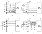
- FIGS. 2A to 2D show an example in which the secondary battery 20 is constituted of four cells E1 to E4 connected in series.
- FIG. 2A is a partial circuit diagram in the case of using discharge resistors R1-R4 of the equalizing circuit as a load for discharging the secondary battery 20 during long-term storage.
- an equalization process is generally performed to equalize the voltage among the plurality of cells E1 to En connected in series from the viewpoint of maintaining the power efficiency and securing the safety.
- discharge circuits are connected to both ends of each of the cells E1 to E4.
- the discharge circuit of the cell E1 is composed of a switch S1 and a discharge resistor R1 connected in series.
- the discharge circuit of the cell E2-E4 has the same configuration as the discharge circuit of the cell E1.
- the control unit 14 identifies the cell with the lowest voltage among the voltages of the plurality of cells E1 to E4.
- the control unit 14 controls the switches of the other cells to the on state to discharge the capacities of the other cells to the voltage of the lowest voltage cell. Thereby, the voltages of the plurality of cells E1-E4 can be made uniform.
- the discharge resistors R1-R4 used in the equalization process are used as a load for discharging the secondary battery 20 during long-term storage.
- FIG. 2B is a partial circuit diagram in the case of using the cooling fan Lf as a load for discharging the secondary battery 20 during long-term storage.
- a cooling fan Lf may be installed to cool the secondary battery 20.
- the cooling fan Lf is often attached to the storage rack.
- the cooling fan Lf is connected to both ends of the cells E1 to E4 via the switch S5.
- the control unit 14 turns on the switch S5 to operate the cooling fan Lf. Thereby, the cells E1 to E4 can be cooled.
- the operation of the cooling fan Lf has the effect of lowering the temperature of the cells E1 to E4. Therefore, there is an effect of suppressing the progress of storage deterioration from the viewpoint of temperature. Further, as compared with the case of using the discharge resistors R1-R4 shown in FIG. 2A, the power consumption is increased, so the discharge time when reducing the SOC of the cells E1 to E4 to the target value is shortened. Can.
- FIG. 2C is a partial circuit diagram when another secondary battery Eb for buffer is used as a load for discharging the secondary battery 20 during long-term storage.
- the buffer secondary battery Eb is connected to both ends of the cells E1 to E4 via the switch S6.
- As the buffer secondary battery Eb a battery having characteristics that are less likely to be stored and deteriorated than the target secondary battery 20 is used, or a battery with a higher dose than the target secondary battery 20 is used.
- the control unit 14 controls the switch S6 to the on state to charge the capacity discharged from the target secondary battery 20 to the buffer secondary battery Eb. .
- the buffer secondary battery Eb is also discharged, and the free capacity is increased.
- FIG. 2D is a partial circuit diagram in the case where both of the discharge resistors R1-R4 and the cooling fan Lf of the equalization circuit are used as a load for discharging the secondary battery 20 during long-term storage.
- the control unit 14 controls the switches S1-S5 to be in the on state to make the discharge resistors R1-R4 conductive and operate the cooling fan Lf.
- the cooling fan Lf can also cool the heat generated by the discharge resistors R1-R4. Therefore, the discharge resistors R1-R4 can be reduced, and the rated current of the discharge resistors R1-R4 can be increased. If the rated current of the discharge resistors R1-R4 is increased, the current flowing through the discharge resistors R1-R4 can be increased, and the discharge time can be shortened.
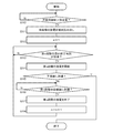
- FIG. 3 is a flow chart showing the flow of discharge processing during long-term storage of the secondary battery 20.
- the discharge control unit 142 reads the multistage discharge plan of the secondary battery 20 from the storage unit 15 (S11).
- the set value is set according to the application of the secondary battery 20. For example, in the case of an EV, it is set to about one week, and in the case of a smartphone, it is set to one to three days.
- the discharge plan includes storage degradation rate indicators and residence times at each stage. Specific examples of the method for determining the storage deterioration rate index and the staying time will be described later.
- the contents of the discharge plan change in environmental conditions such as temperature even during the discharge process based on the discharge plan (including both during the discharge process and the interval period between the discharge process and the next discharge process). If it does, it can be changed according to the change.
- the discharge control unit 142 sets 1 as an initial value to the parameter n (S12).
- the discharge control unit 142 starts the discharge of the nth stage (S14).
- the storage deterioration rate index reaches the lower limit (Y in S15)
- the discharge control unit 142 ends the discharge process of the secondary battery 20 during long-term storage.
- the comparison between the storage deterioration rate index and the lower limit value may be performed at the end of the n-th stage discharge. As a result of the comparison, when the storage deterioration rate index is equal to or less than the lower limit value, the discharge process during long-term storage is ended without shifting to the discharge of the next stage.
- the discharge process during long-term storage is also stopped when normal use of the secondary battery 20 is resumed.
- the discharge control unit 142 ends the discharge of the nth stage (S17).
- the discharge control unit 142 increments the parameter n (S18), and transitions to step S13.
- FIG. 4 is a diagram for describing an example of a discharge plan during long-term storage of the secondary battery 20.
- Storage degradation basically depends largely on SOC and temperature. The higher the SOC or the higher the temperature, the easier the storage deterioration progresses.
- the temperature is constant at normal temperature (25 ° C.), and other environmental parameters and deterioration parameters are also constant. That is, the simplified model in which the storage deterioration rate index coincides with the SOC is shown.
- the SOC of the first stage is 100%, the staying time is T1, and the storage time product is S1.
- the SOC at the second stage is 80%, the staying time is T2, and the storage time product is S2.
- the SOC of the third stage is 50%, the staying time is T3, and the storage time product is S3.
- the lower limit value of SOC is 45%.
- the total storage time product S1 + S2 + S3 is limited to a predetermined upper limit value or less. This restriction is a restriction for limiting the time scale of discharge processing during long-term storage.
- the stay time of the high SOC region where the storage deterioration rate is relatively fast is set short, and the stay time of the low SOC region where the storage deterioration rate is relatively slow is set long. That is, the stay time is set to be longer as the stage progresses.
- the decrease value ⁇ SOC of SOC in transition between stages is set to be constant or smaller as the stages progress.
- the specific SOC and the staying time in each stage can be determined based on the usage results at the time of discharge after long-term storage.
- the maker or operation management company of the battery system 1 samples a large number of data of discharge capacity (discharge ⁇ SOC) discharged by use after long-term storage.
- Discharge ⁇ SOC is defined by the difference between SOC at the start of discharge after long-term storage and SOC at the end of discharge.
- the sample data is aggregated for each attribute whose usage mode of the secondary battery 20 at the time of resumption of use after long-term storage is similar. For example, it is totaled for every product in which the battery system 1 is mounted. Furthermore, it may be tabulated for each product destination. Since the temperature and the user's habits differ depending on the destination, if the destination is considered and classified, more accurate data classification becomes possible.
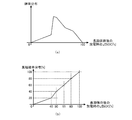
- FIGS. 5A and 5B are diagrams showing an example of a graph in which the discharge ⁇ SOC at the time of discharge after long-term storage is summarized.
- FIG. 5 (a) is a graph showing the probability distribution (Probability Density Function: PDF) of the discharge ⁇ SOC during discharge after long-term storage
- FIG. 5 (b) is the accumulation of discharge ⁇ SOC during discharge after long-term storage
- It is a graph which shows probability distribution (Cumulative Distribution Function: CDF).
- FIG. 5B is a graph in which the probability distribution of FIG. 5A is rewritten to a cumulative probability distribution.
- the number of users who discharge the SOC of about 45% at the time of discharge after long-term storage is the largest.
- the designer determines the lower limit value of the SOC of the discharge process during long-term storage, based on the actual use at the time of discharge after long-term storage.
- the lower limit value of SOC is determined to 45%. That is, a capacity of 45% of SOC is ensured for the secondary battery 20 as the minimum ensured capacity of the secondary battery 20.
- the lower limit value of SOC may be a value customized for each user.
- the designer determines the ratio of storage time product in a plurality of stages constituting the discharge plan based on the probability distribution of discharge ⁇ SOC at the time of discharge after long-term storage.
- the storage time product S1 of the first stage in the discharge plan the storage time product S2 of the second stage: the ratio of the storage time product S3 of the third stage and the probability of the discharge ⁇ SOC
- Storage time product S1 of the first stage, storage time product of the second stage so that the ratio of the area corresponding to the second stage to the area corresponding to the second stage is proportional to the area corresponding to the first stage of the distribution
- the storage time product S3 of S2 and the third stage is determined (probability distribution of S1: S2: S3 ⁇ discharge ⁇ SOC).
- the area corresponding to the first stage of the probability distribution of the discharge ⁇ SOC is the area of the region sandwiched between 0% and the first stage SOC (100% in FIG. 4).
- the area corresponding to the second stage of the probability distribution of the discharge ⁇ SOC is the area of the region sandwiched between 0% and the SOC of the second stage (80% in FIG. 4).
- the area corresponding to the third stage of the probability distribution of the discharge ⁇ SOC is the area of the region sandwiched between 0% and the SOC of the third stage (50% in FIG. 4).
- the ratio of the storage time product S1 of the first stage in the discharge plan: the storage time product S2 of the second stage: the storage time product S3 of the third stage may be weighted.
- the weighting factor W is set to a larger value as the stage progresses (W_S1 ⁇ W_S2 ⁇ W_S3).
- FIG. 5 (b) shows an example of classifying the discharge ⁇ SOC in 20% increments of the cumulative probability distribution.
- the cumulative probability distribution of the discharge ⁇ SOC is 20%, and the use of the discharge ⁇ SOC of 40% or less is covered.
- the cumulative probability distribution of the discharge ⁇ SOC is 40%, and the use of the discharge ⁇ SOC of 50% or less is covered.
- the cumulative probability distribution of the discharge ⁇ SOC is 60%, and the use of the discharge ⁇ SOC of 65% or less is covered.
- the cumulative probability distribution of the discharge ⁇ SOC is 80%, and the use of the discharge ⁇ SOC of 80% or less is covered.
- the cumulative probability distribution of the discharge ⁇ SOC is 100%, and the use of the discharge ⁇ SOC of 100% or less is covered.
- the designer determines the SOC of each stage in the discharge plan based on the classified discharge ⁇ SOC.
- the SOC of the first stage is set to 100%
- the SOC of the second stage is set to 80%
- the SOC of the third stage is set to 65%.
- the ratio of SOC1 of the first stage to SOC2 of the second stage to SOC3 of the third stage in the discharge plan may be weighted.
- the weighting factor W is set to a larger value as the stage progresses (W_SOC1 ⁇ W_SOC2 ⁇ W_SOC3).
- the designer stores in the storage unit 15 the discharge plan including the SOC and the stay time in each stage generated from the above findings.
- data other than discharge ⁇ SOC such as temperature and SOH can be collected from sample data
- the horizontal axis in FIGS. 5 (a) and 5 (b) is the storage deterioration rate index before and after discharge during discharge after long-term storage. It becomes a difference.
- the above probability distribution can also be updated by learning.
- the discharge control unit 142 acquires data such as the discharge ⁇ SOC, temperature, and the like and stores the data in the storage unit 15 each time a discharge after long-term storage of the secondary battery 20 in the battery system 1 occurs.
- the discharge control unit 142 updates the current probability distribution stored in the storage unit 15 to a probability distribution including the sample data.
- the discharge control unit 142 updates the discharge plan including the discharge deterioration rate index (or SOC) and the staying time in each stage based on the updated probability distribution. As the number of sample data collected from the self battery system 1 increases, the probability distribution more closely reflects the behavior of the user of the battery system 1 and a more accurate discharge plan can be generated.
- the discharge control unit 142 can adjust the lower limit value of the SOC according to the detected temperature of the cells E1 to E4 at the start of the discharge process during long-term storage. For example, the lower the SOC lower limit value is set as the temperature of the cells E1 to E4 is higher.
- the lower limit value of the discharge degradation rate index does not have to be changed. The influence of the temperature of the cells E1 to E4 is reflected in the value of the discharge degradation rate index. That is, when the temperature of the cells E1 to E4 is high, the discharge deterioration rate index is increased, so that it is difficult to reach the lower limit value.
- the storage degradation rate index (or SOC) is reduced to the target value by discharging the capacity of the secondary battery 20 in multiple stages during long-term storage of the battery system 1
- the stay time in a state in which the storage deterioration rate index (or SOC) is high is shortened, and the stay time in a state in which the storage deterioration rate index (or SOC) is low is lengthened.
- control is performed such that the staying time becomes longer as the stage progresses.
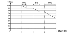
- FIG. 6 is a view for explaining a modification of the discharge plan during long-term storage of the secondary battery 20.
- the stay time of the high SOC region is set long, and the stay time of the low SOC region is set short.
- the time until the first discharge is made longer, and if it is not used before, it is judged that it will not be used thereafter, and the time until the next discharge operation is shortened. That is, the staying time in each stage is set shorter as the stage progresses.
- the decrease value ⁇ SOC of the SOC in the transition between the stages is set to be larger as the stage progresses.
- the SOC and the stay time in each stage are set such that the storage time product decreases as the stage progresses.
- the SOC and the residence time in each stage may be set so that the storage time products in the plurality of stages become substantially equal.
- FIG. 6 shows an example in the case of discharging a 50 [Ah] battery module with a discharge capacity of 50 [mAh].
- the discharge process during long-term storage starts.
- the capacity of SOC 10% is discharged over 10 hours.
- the capacity of SOC 15% is discharged over 15 hours.
- the capacity of SOC 25% is discharged over 25 hours.
- SOC 50% which is the target value of SOC during long-term storage, is reached.
- the SOC is simply used, but the storage deterioration rate index may be used instead of the SOC as in the above embodiment.
- the discharge plan is not necessarily limited to one created based on the use results, and an assumed value It may be created based on The discharge plan in that case is also in accordance with the storage degradation rate index (or SOC), the staying time, and the storage time product constraints described above.
- the embodiment may be specified by the following items.
- An estimation unit (141) When the non-use state of the secondary battery (20) continues for a predetermined period, the secondary battery (20) is gradually reduced so that the index indicating the progress of storage deterioration of the secondary battery (20) gradually decreases.
- a discharge control unit (142) for discharging the The index includes a parameter dependent on the SOC of the secondary battery, The battery management device (10), wherein the value of the index and the stay time in each stage are set such that the product of the value of the index and the stay time has a predetermined relationship among a plurality of stages. .
- the ratio of the product among the plurality of stages is a long-term non-use generated by sampling a plurality of data of capacity discharged by use after the non-use state of the secondary battery (20) continues for a predetermined period.
- the value of the indicator at each stage is the discharge capacity after long-term non-use generated by sampling a plurality of data of the capacity discharged by use after the non-use state of the secondary battery (20) continues for a predetermined period.
- the battery management device (10) according to any one of items 1, 3 and 4, wherein the cumulative probability distribution is set so as to be substantially equally spaced based on the cumulative probability distribution. ). According to this, it is possible to create a discharge plan in which a suitable dischargeable capacity is secured.
- the battery management device (10) according to Item 1, wherein the staying time in each stage is set to be shorter as the stage progresses. According to this, it is possible to suppress the storage deterioration while preventing the dischargeable capacity from becoming too small.
- the battery management device (10) according to any one of items 1 and 7, wherein the value of the indicator and the staying time in each stage are set so that the product decreases as the stage progresses. ). According to this, it is possible to suppress the storage deterioration while preventing the dischargeable capacity from becoming too small.
- the lower limit value of the indicator at the time of discharge by the discharge control unit (142) due to the non-use state of the secondary battery (20) continuing for a predetermined period, the non-use state of the secondary battery (20) continues for a predetermined period The battery management device (10) according to any one of items 1 to 8, wherein the battery management device (10) is set based on the usage record at the time of discharge after the battery pack.
- the lower limit value of the index can be set to a suitable value.
- the lower limit value of the indicator at the time of discharge by the discharge control unit (142) when the non-use state of the secondary battery (20) continues for a predetermined period is a parameter depending on the environment and / or the secondary battery (20.
- the battery management device (10) according to any one of items 1 to 9, wherein the battery management device (10) is adjusted according to a parameter depending on the degree of deterioration of According to this, the lower limit value of the index can be adjusted to a suitable value.
- the index includes an environment-dependent parameter and / or a parameter dependent on the degree of deterioration of the secondary battery (20) in addition to the SOC-dependent parameter.
- the battery management device (10) according to any one of the items. According to this, storage degradation of the secondary battery (20) can be managed more accurately.
- a battery system (1) comprising: According to this, it is possible to achieve both the request for suppressing storage deterioration during long-term storage of the secondary battery (20) and the request for securing the dischargeable capacity.
- the secondary battery (20) includes a plurality of cells (E1-En) connected in series.
- the battery system (1) further includes a plurality of equalizing discharge resistors (R1-R4) connected in parallel with the plurality of cells (E1-En), respectively.
- the battery system (1) according to Item 12, characterized in that the capacity is discharged. According to this, it is possible to reduce the capacity of the secondary battery (20) while the target load is not in operation.
- the battery system (1) further includes a fan (Lf) connected in parallel to the secondary battery (20) for cooling the secondary battery (20), The discharge control unit (142) causes the fan (Lf) to discharge the capacity of the secondary battery (20) when the secondary battery (20) is discharged when the non-use state continues for a predetermined period.
- the battery system (1) according to Item 12 characterized in that According to this, it is possible to reduce the capacity of the secondary battery (20) while the target load is not in operation.
- the battery system (1) further includes a buffer battery (Eb) connected in parallel to the secondary battery (20), The discharge control unit (142) discharges the capacity of the secondary battery (20) to the buffer battery (Eb) when the secondary battery (20) is discharged when the non-use state continues for a predetermined period.
- the battery system (1) according to Item 12 characterized in that According to this, it is possible to reduce the capacity of the secondary battery (20) while the target load is not in operation.
- the battery system (1) according to any one of items 12 to 15, The DC power supplied from the secondary battery (20) is converted to AC power during power running and supplied to a motor (3) in the vehicle, and the AC power supplied from the motor (3) is converted to DC power during regeneration.
- a vehicle power supply system comprising: According to this, it is possible to achieve both the request for storage deterioration suppression and the request for securing the dischargeable capacity during long-term storage of the vehicle-mounted secondary battery (20).
Landscapes
- Engineering & Computer Science (AREA)
- Power Engineering (AREA)
- Manufacturing & Machinery (AREA)
- Chemical & Material Sciences (AREA)
- Chemical Kinetics & Catalysis (AREA)
- Electrochemistry (AREA)
- General Chemical & Material Sciences (AREA)
- Life Sciences & Earth Sciences (AREA)
- Sustainable Development (AREA)
- Sustainable Energy (AREA)
- Transportation (AREA)
- Mechanical Engineering (AREA)
- Physics & Mathematics (AREA)
- General Physics & Mathematics (AREA)
- Secondary Cells (AREA)
- Combinations Of Printed Boards (AREA)
- Charge And Discharge Circuits For Batteries Or The Like (AREA)
Abstract
状態推定部141は、二次電池20の電圧、電流、温度の少なくとも1つをもとに、二次電池20のSOC(State Of Charge)を含む二次電池20の状態を推定する、放電制御部142は、二次電池20の不使用状態が所定期間継続すると、二次電池20の保存劣化の進行しやすさを示す指標が段階的に減少するように、二次電池20を放電させる。当該指標には、二次電池20のSOCに依存するパラメータが含まれている。当該指標の値と滞在時間との積が複数の段階間において所定の関係になるように、各段階における指標の値と滞在時間が設定されている。
Description
本発明は、二次電池を管理する電池管理装置、電池システム、及び車両用電源システムに関する。
近年、リチウムイオン電池の需要が拡大している。リチウムイオン電池は、車載用途(例えば、HEV、PHEV、EV)、定置型蓄電用途、電子機器用途(例えば、ノートPC、スマートフォン)など、様々な用途に使用されている。特にHEV、PHEV、EVの出荷台数が増えてきており、車載用のリチウムイオン電池の出荷が伸びている。
長期出張などにより、自家用のEVや蓄電システムを長期間使用しない場合が発生し得る。このような電池を長期保存する場合において、電池を高SOCのまま放置すると、速いペースで保存劣化が進行する。電池の保存劣化を抑制するため、放電が不要となる可能性が高い時間帯においてSOCを比較的低く維持する手法(例えば、特許文献1参照)や、車両の長期間の停車が予測されるとき、充電の開始を遅らせる手法(例えば、特許文献2参照)が提案されている。
一方で、電池システムには、必要な時に必要な容量を放電できることが要求される。例えば、車載電池の長期保存の場合にSOCを低く維持しすぎると、長期保存後に使用する際の走行距離が短くなってしまう。
本発明はこうした状況に鑑みなされたものであり、その目的は、二次電池の長期保存時の劣化抑制と、長期保存後の使用における放電可能容量の確保を両立させる技術を提供することにある。
上記課題を解決するために、本発明のある態様の電池管理装置は、二次電池の電圧、電流、温度の少なくとも1つをもとに、前記二次電池のSOC(State Of Charge)を含む前記二次電池の状態を推定する状態推定部と、前記二次電池の不使用状態が所定期間継続すると、前記二次電池の保存劣化の進行しやすさを示す指標が段階的に減少するように、前記二次電池を放電させる放電制御部と、を備える。前記指標には、前記二次電池のSOCに依存するパラメータが含まれており、前記指標の値と滞在時間との積が複数の段階間において所定の関係になるように、各段階における前記指標の値と滞在時間が設定されている。
なお、以上の構成要素の任意の組み合わせ、本発明の表現を方法、装置、システム、コンピュータプログラムなどの間で変換したものもまた、本発明の態様として有効である。
本発明によれば、二次電池の長期保存時の劣化抑制と、長期保存後の使用における放電可能容量の確保を両立させることができる。
図1は、本発明の実施の形態に係る電池システム1の概略構成を説明するための図である。図1に示す例は、本実施の形態に係る電池システム1が、車両の駆動用電池として車両に搭載される例である。電池システム1は、リレーRL及びインバータ2を介してモータ3に接続される。インバータ2は力行時、電池システム1から供給される直流電力を交流電力に変換してモータ3に供給する。回生時、モータ3から供給される交流電力を直流電力に変換して電池システム1に供給する。なおリレーRLは電池システム1と車両側とを電気的に遮断するための素子の一例であり、両者の間の電流を遮断できるスイッチ機能を備える素子であれば、他の種類の素子を用いてもよい。
電池システム1は二次電池20及び電池管理装置10を備える。二次電池20は複数のセルE1~Enが直列接続されて形成される。セルには、リチウムイオン電池セル、ニッケル水素電池セル、鉛電池セル等を用いることができる。以下、本明細書ではリチウムイオン電池セル(公称電圧:3.6-3.7V)を使用する例を想定する。セルE1~Enの直列数は、モータ3の電圧に応じて決定される。
複数のセルE1-Enと直列にシャント抵抗Rsが接続される。シャント抵抗Rsは電流検出素子として機能する。なおシャント抵抗Rsの代わりにホール素子を用いてもよい。また複数のセルE1-Enの温度を検出するための温度センサT1が設置される。温度センサT1には例えば、サーミスタを使用することができる。
電池管理装置10は電圧検出部11、温度検出部12、電流検出部13、制御部14、記憶部15及び駆動部16を備える。電圧検出部11は、直列接続された複数のセルE1-Enの各ノードと複数の電圧線で接続され、隣接する2本の電圧線間の電圧をそれぞれ検出することにより、各セルE1-Enの電圧を検出する。電圧検出部11は、検出した各セルE1-Enの電圧を制御部14に出力する。電圧検出部11は例えば、ASIC(Application Specific Integrated Circuit)で構成できる。電圧検出部11は、マルチプレクサ及びA/D変換器を含む。マルチプレクサは、複数のセルE1-Enの各電圧値を所定の順番でA/D変換器に出力し、A/D変換器は、マルチプレクサから入力されるアナログ信号の電圧値をデジタル信号の電圧値に変換する。
温度検出部12は温度センサT1の出力値をもとに複数のセルE1-Enの温度を推定し、推定した温度を制御部14に出力する。電流検出部13は、シャント抵抗Rsの両端に接続された誤差増幅器を含む。誤差増幅器はシャント抵抗Rsの両端電圧を検出する。電流検出部13は当該両端電圧をもとに、二次電池20に流れる電流を検出し、検出した電流を制御部14に出力する。
制御部14は例えば、CPU、DSP(Digital Signal Processor)、FPGA(Field-Programmable Gate Array)等で構成できる。制御部14の詳細は後述する。記憶部15は各種の情報を記憶する。記憶部15は例えば、不揮発性メモリで構成できる。駆動部16は、制御部14からの切替指示信号を受けてリレーRLのオン/オフを制御するための駆動信号を生成し、リレーRLに供給する。
制御部14は、電圧検出部11、温度検出部12及び電流検出部13により検出された複数のセルE1-Enの電圧、電流、温度をもとに二次電池20を管理する。例えば制御部14は、セルE1~Enの少なくとも1つに過電圧、過小電圧、過電流、温度異常が発生すると、駆動部16にリレーRLをターンオフさせ、セルE1~Enを保護する。また制御部14はセルE1~Enの均等化処理を実行する。
制御部14は、本実施の形態において注目する機能を実現するための機能ブロックとして、状態推定部141及び放電制御部142を含む。状態推定部141は複数のセルE1-EnのSOC(State Of Charge)及びSOH(State Of Health)を推定する。
SOCは、OCV(Open Circuit Voltage)法または電流積算法により推定できる。OCV法は、電圧検出部11により検出されるOCVと、記憶部15に保持されるSOC-OCVカーブの特性データをもとにSOCを推定する方法である。電流積算法は、電圧検出部11により検出される充放電開始時のOCVと、電流検出部13により検出される電流の積算値をもとにSOCを推定する方法である。
SOHは、初期の満充電容量に対する現在の満充電容量の比率で規定され、数値が低いほど(0%に近いほど)劣化が進行していることを示す。SOHは、内部抵抗との相関関係をもとに推定することができる。内部抵抗は、電池に所定の電流を所定時間流した際に発生する電圧降下を、当該電流で割ることにより推定することができる。内部抵抗は温度が上がるほど低下する関係にあり、電池の劣化が進行するほど増加する関係にある。電池の劣化は充放電回数が増加するにつれ進行する。また電池の劣化は個体差や使用環境にも依存する。従って使用期間が長くになるにつれ基本的に、複数のセルE1-Enの容量のばらつきが大きくなっていく。
放電制御部142は、二次電池20の長期保存時の劣化を抑制するために二次電池20の容量を放電する。放電制御部142は、二次電池20の保存劣化の進行しやすさを示す指標(以下、本明細書では保存劣化速度指標という)を生成し、保存劣化速度指標が段階的に低下するように二次電池20を放電させる。保存劣化速度指標は0~100%の範囲の値をとり、値が大きいほど保存劣化速度が速いことを示す。
保存劣化速度指標には、SOCに依存するパラメータが含まれる。SOC、あるいはSOCに応じて単調変化する任意のパラメータ(電圧、SOP(State Of Power)など)のうち、少なくとも一つを使用できる。電圧として、セル電圧、モジュール電圧、システム電圧を使用することができる。直列接続された複数のセルが設けられる場合、セル電圧は、複数のセルの電圧の最大値を使用してもよいし、平均値を使用してもよい。直列接続された複数のモジュールが使用される場合、システム電圧は、複数のモジュール電圧の合算値になる。
また保存劣化速度指標には、二次電池20のSOCに依存しないパラメータも含めることができる。SOCに依存しないパラメータには、環境パラメータと劣化パラメータが含まれる。環境パラメータとして、各種の温度(セルの表面、セルの内部、モジュール、システム、外気など)を使用することができる。温度が高いほど、保存劣化速度指標が上昇する関係にある。なお環境パラメータとして湿度を使用することもできる。
劣化パラメータとして、SOH、R-SOH、内部抵抗値、満充電容量、総充電/総放電容量、サイクル数、総充電/総放電時間、総使用時間、最大/最小電圧履歴、最大/最小温度履歴の少なくとも1つを使用することができる。セルの劣化が進行しているほど、保存劣化速度指標が上昇する関係にある。
保存劣化速度指標における各パラメータの寄与度は、二次電池20の種類ごとに実験やシミュレーションにもとづき決定される。保存劣化速度指標におけるパラメータの寄与度としては、SOCと温度の寄与度が支配的である。
図2(a)-(d)は、長期保存中の二次電池20の放電方法の具体例を示す図である。図2(a)-(d)では二次電池20が、直列接続された4つのセルE1-E4で構成される例を示している。
図2(a)は、長期保存中の二次電池20の放電用の負荷として、均等化回路の放電抵抗R1-R4を利用する場合の部分回路図である。リチウムイオン電池では電力効率の維持および安全性担保の観点から、直列接続された複数のセルE1~En間において電圧を均等化する均等化処理が実行されることが一般的である。
図2(a)に示す例では、セルE1-E4のそれぞれの両端に放電回路が接続される。セルE1の放電回路は、直列接続されたスイッチS1と放電抵抗R1により構成される。セルE2-E4の放電回路も、セルE1の放電回路と同様の構成である。制御部14は均等化処理する際、複数のセルE1-E4の電圧の内、最も電圧が低いセルを特定する。制御部14は、他のセルのスイッチをオン状態に制御して、当該最も電圧が低いセルの電圧まで、他のセルの容量を放電する。これにより、複数のセルE1-E4の電圧を揃えることができる。図2(a)に示す例では、均等化処理に使用する放電抵抗R1-R4を、長期保存中の二次電池20の放電用の負荷として利用する。
図2(b)は、長期保存中の二次電池20の放電用の負荷として、冷却ファンLfを利用する場合の部分回路図である。電池システム1では、二次電池20を冷却するために冷却ファンLfが設置されることがある。特に定置型の大型蓄電システムでは、蓄電ラックに冷却ファンLfが取り付けられることが多い。
図2(b)に示す例では、セルE1-E4の両端に、スイッチS5を介して冷却ファンLfが接続される。制御部14はセルE1~E4の温度が所定値以上に上昇したとき、スイッチS5をオン状態に制御して、冷却ファンLfを稼働させる。これにより、セルE1~E4を冷却することができる。
図2(b)に示す例では冷却ファンLfが稼働することにより、セルE1~E4の温度を低下させる効果もある。従って保存劣化の進行を温度面からも抑制する効果がある。また図2(a)に示した放電抵抗R1-R4を使用する場合と比較して、消費電力が大きくなるため、セルE1~E4のSOCを目標値まで低下させる際の放電時間を短縮することができる。
図2(c)は、長期保存中の二次電池20の放電用の負荷として、バッファ用の別の二次電池Ebを利用する場合の部分回路図である。セルE1-E4の両端に、スイッチS6を介してバッファ用の二次電池Ebが接続される。バッファ用の二次電池Ebには、対象となる二次電池20より保存劣化しにくい特性の電池を使用するか、対象となる二次電池20より高用量の電池を使用する。制御部14は長期保存中の二次電池20を放電させる際、スイッチS6をオン状態に制御して、対象となる二次電池20から放電される容量をバッファ用の二次電池Ebに充電させる。対象となる二次電池20の使用が再開されると、バッファ用の二次電池Ebからも放電され、空き容量が増加される。
図2(d)は、長期保存中の二次電池20の放電用の負荷として、均等化回路の放電抵抗R1-R4と冷却ファンLfの両方を利用する場合の部分回路図である。制御部14は長期保存中の二次電池20を放電させる際、スイッチS1-S5をオン状態に制御して、放電抵抗R1-R4を導通させるとともに冷却ファンLfを稼働させる。冷却ファンLfは、放電抵抗R1-R4の発熱も冷却することができる。従って放電抵抗R1-R4を小さくすることができ、放電抵抗R1-R4の定格電流を上げることができる。放電抵抗R1-R4の定格電流を上げれば、放電抵抗R1-R4に流れる電流を多くすることができ、放電時間を短縮することができる。
図3は、二次電池20の長期保存中の放電処理の流れを示すフローチャートである。放電制御部142は、二次電池20の不使用期間が設定値を超えると(S10のY)、記憶部15から二次電池20の多段階の放電計画を読み出す(S11)。当該設定値は、二次電池20の用途に応じて設定される。例えば、EVであれば1週間程度、スマートフォンであれば1~3日に設定される。放電計画は、各段階における保存劣化速度指標と滞在時間を含んでいる。この保存劣化速度指標と滞在時間の決定方法の具体例は後述する。なお放電計画の内容は、放電計画に基づく放電処理の実行中(放電処理の最中と、放電処理と次の放電処理とのインターバル期間の両方を含む)においても、温度などの環境条件が変化した場合、その変化に応じて変更可能である。
放電制御部142は、パラメータnに初期値として1を設定する(S12)。放電制御部142は、第n段階の滞在終了時刻が到来すると(S13のY)、第n段階の放電を開始する(S14)。放電制御部142は、保存劣化速度指標が下限値に到達すると(S15のY)、二次電池20の長期保存中の放電処理を終了する。なお、保存劣化速度指標と下限値との比較は、第n段階の放電が終了した時点で行ってもよい。当該比較の結果、保存劣化速度指標が下限値以下の場合、次の段階の放電に移行せずに長期保存中の放電処理を終了する。なお、長期保存中の放電処理は、二次電池20の通常の使用が再開した場合も停止する。
放電制御部142は、保存劣化速度指標が第n段階の目標値に到達すると(S15のN、S16のY)、第n段階の放電を終了する(S17)。放電制御部142は、パラメータnをインクリメントして(S18)、ステップS13に遷移する。
図4は、二次電池20の長期保存時における放電計画の実施例を説明するための図である。保存劣化は基本的にSOCと温度に大きく依存している。SOCが高いほど、又は温度が高いほど保存劣化が進行しやすくなる。図4に示す例は、温度が常温(25℃)で一定とし、その他の環境パラメータと劣化パラメータも一定としている。即ち、保存劣化速度指標がSOCと一致する簡易モデルを示している。
放電計画では、複数の段階における保存劣化速度指標(=SOC)の値と滞在時間の積(以下、保存時間積という)の関係が考慮される。図4に示す例において第1段階のSOCは100%、滞在時間はT1、保存時間積はS1である。第2段階のSOCは80%、滞在時間はT2、保存時間積はS2である。第3段階のSOCは50%、滞在時間はT3、保存時間積はS3である。SOCの下限値は45%である。保存時間積の合計S1+S2+S3は、所定の上限値以下に制限される。この制約は、長期保存中の放電処理のタイムスケールの枠をはめるための制約である。
実施例では、保存劣化速度が相対的に早くなる高SOC領域の滞在時間を短く設定し、保存劣化速度が相対的に遅くなる低SOC領域の滞在時間を長く設定する。即ち、段階が進むほど滞在時間が長くなるように設定される。実施例に係る放電計画では、段階間の遷移におけるSOCの減少値ΔSOCは、一定または段階が進むほど小さくなるように設定される。
実施例に係る放電計画では、段階が進むほど保存時間積が大きくなるように(S1<S2<S3)、各段階におけるSOCと滞在時間が設定される。また、複数の段階における保存時間積が実質的に等しくなるように(S1=S2=S3)、各段階におけるSOCと滞在時間が設定されてもよい。
各段階における具体的なSOCと滞在時間は、長期保存後の放電時の使用実績をもとに決定することができる。電池システム1のメーカまたは運用管理会社は、長期保存後の使用により放電された放電容量(放電ΔSOC)のデータを多数サンプリングする。放電ΔSOCは、長期保存後の放電開始時のSOCと放電終了時のSOCの差分で規定される。サンプルデータは、長期保存後の使用再開時における二次電池20の使用態様が類似する属性ごとに集計される。例えば、電池システム1が搭載される製品ごとに集計される。さらに製品の仕向地ごとに集計されてもよい。仕向地により気温やユーザの習慣が異なるため、仕向地を考慮して分類すると、より高精度なデータ分類が可能となる。
図5(a)、(b)は、長期保存後の放電時の放電ΔSOCを集計したグラフの一例を示す図である。図5(a)は、長期保存後の放電時の放電ΔSOCの確率分布(Probability Density Function:PDF)を示すグラフであり、図5(b)は、長期保存後の放電時の放電ΔSOCの累積確率分布(Cumulative Distribution Function:CDF)を示すグラフである。図5(b)は、図5(a)の確率分布を、累積確率分布に書き換えたグラフである。
図5(a)に示すグラフを見ると、長期保存後の放電時に約45%のSOCを放電するユーザが最も多いことが分かる。設計者は、長期保存後の放電時の使用実績をもとに、長期保存中の放電処理のSOCの下限値を決定する。この例ではSOCの下限値を45%に決定する。即ち、二次電池20の最低確保容量として、SOC45%の容量を二次電池20に確保する。なお、SOCの下限値はユーザごとにカスタマイズされた値を使用してもよい。
設計者は、長期保存後の放電時の放電ΔSOCの確率分布をもとに、放電計画を構成する複数の段階における保存時間積の比率を決定する。図4、図5(a)に示す例では、放電計画における第1段階の保存時間積S1:第2段階の保存時間積S2:第3段階の保存時間積S3の比率と、放電ΔSOCの確率分布の第1段階に対応する面積:第2段階に対応する面積:第3段階に対応する面積の比率とが比例するように、第1段階の保存時間積S1、第2段階の保存時間積S2及び第3段階の保存時間積S3が決定される(S1:S2:S3∝放電ΔSOCの確率分布)。
放電ΔSOCの確率分布の第1段階に対応する面積は、0%と第1段階のSOC(図4では100%)との間に挟まれた領域の面積である。放電ΔSOCの確率分布の第2段階に対応する面積は、0%と第2段階のSOC(図4では80%)との間に挟まれた領域の面積である。放電ΔSOCの確率分布の第3段階に対応する面積は、0%と第3段階のSOC(図4では50%)との間に挟まれた領域の面積である。
なお、放電計画における第1段階の保存時間積S1:第2段階の保存時間積S2:第3段階の保存時間積S3の比率は、重み付けされてもよい。その場合、重み係数Wは、段階が進むほど大きな値に設定される(W_S1<W_S2<W_S3)。
また設計者は、長期保存後の放電時の放電ΔSOCの累積確率分布をもとに、当該累積確率分布が実質的に等間隔になるように、長期保存後の放電時の放電ΔSOCを分類してもよい。図5(b)では、累積確率分布を20%刻みで放電ΔSOCを分類した例を示している。放電ΔSOCの累積確率分布が20%で、放電ΔSOCが40%以下の使用がカバーされる。放電ΔSOCの累積確率分布が40%で、放電ΔSOCが50%以下の使用がカバーされる。放電ΔSOCの累積確率分布が60%で、放電ΔSOCが65%以下の使用がカバーされる。放電ΔSOCの累積確率分布が80%で、放電ΔSOCが80%以下の使用がカバーされる。放電ΔSOCの累積確率分布が100%で、放電ΔSOCが100%以下の使用がカバーされる。
設計者は、分類した放電ΔSOCをもとに、放電計画における各段階のSOCを決定する。図5(b)に示す例では第1段階のSOCを100%に設定し、第2段階のSOCを80%に設定し、第3段階のSOCを65%に設定する。
なお、放電計画における第1段階のSOC1:第2段階のSOC2:第3段階のSOC3の比率は、重み付けされてもよい。その場合、重み係数Wは、段階が進むほど大きな値に設定される(W_SOC1<W_SOC2<W_SOC3)。
設計者は、以上の知見から生成した各段階におけるSOCと滞在時間を含む放電計画を、記憶部15に保存する。なお、サンプルデータから温度やSOH等の放電ΔSOC以外のデータを収集できる場合は、図5(a)、(b)の横軸は、長期保存後の放電時における放電前後の保存劣化速度指標の差分となる。
上記の確率分布は学習により更新することも可能である。放電制御部142は、自己の電池システム1における二次電池20の長期保存後の放電が発生する度に、放電ΔSOCや温度などのデータを取得して記憶部15に保存する。自己の電池システム1から1つ以上のサンプルデータが新たに収集されると、放電制御部142は、記憶部15に保存される現在の確率分布を、当該サンプルデータを含む確率分布に更新する。放電制御部142は、更新後の確率分布をもとに各段階における放電劣化速度指標(またはSOC)と滞在時間を含む放電計画を更新する。自己の電池システム1から収集されるサンプルデータの数が多くなるほど、当該電池システム1のユーザの行動様式をより反映した確率分布となり、より高精度な放電計画を生成することができる。
放電制御部142は、長期保存中の放電処理の開始時に、セルE1-E4の検出温度に応じて、SOCの下限値を調整することができる。例えば、セルE1-E4の温度が高いほどSOCの下限値を低く設定する。なお放電劣化速度指標を使用する場合において、放電劣化速度指標のパラメータに温度が含まれている場合、放電劣化速度指標の下限値は変動させる必要はない。セルE1-E4の温度の影響は、放電劣化速度指標の値に反映される。即ち、セルE1-E4の温度が高い場合、放電劣化速度指標が上昇するため下限値に到達しにくくなる。
以上説明したように本実施の形態によれば、電池システム1が長期保存中において、二次電池20の容量を多段階で放電することにより、保存劣化速度指標(またはSOC)を目標値まで低下させる。その際、保存劣化速度指標(またはSOC)が高い状態の滞在時間を短くし、保存劣化速度指標(またはSOC)が低い状態の滞在時間を長くする。例えば、段階が進むにつれ滞在時間が長くなるように制御する。また段階が進むにつれ保存時間積(=保存劣化速度指標×滞在時間)が大きくなるように制御する。これにより、長期保存時の保存劣化抑制の要請と放電可能容量確保の要請を両立させることができる。
また、SOCの下限値を温度に応じて変化させることにより、また保存劣化速度指標のパラメータに温度を含めることにより、保存劣化抑制と放電可能容量のバランスを調整することができる。また長期保存後の使用実績をもとに生成された長期保存中の放電計画を使用することにより、好適な放電可能容量を確保することができる。
以上、本発明を実施の形態をもとに説明した。実施の形態は例示であり、それらの各構成要素や各処理プロセスの組み合わせにいろいろな変形例が可能なこと、またそうした変形例も本発明の範囲にあることは当業者に理解されるところである。
図6は、二次電池20の長期保存時における放電計画の変形例を説明するための図である。変形例では、実施例と反対に高SOC領域の滞在時間を長く設定し、低SOC領域の滞在時間を短く設定している。最初の放電までの時間を長くとり、それまでに使用されない場合、以後も使用されないと判断し、次の放電動作までの時間を短くしていく。即ち、各段階における滞在時間は、段階が進むほど短く設定される。
変形例に係る放電計画では、段階間の遷移におけるSOCの減少値ΔSOCが、一定または段階が進むほど大きくなるように設定される。また変形例に係る放電計画では、段階が進むほど保存時間積が小さくなるように、各段階におけるSOCと滞在時間が設定される。また複数の段階における保存時間積が実質的に等しくなるように、各段階におけるSOCと滞在時間が設定されてもよい。
図6は、50[Ah]の電池モジュールを、50[mAh]の放電容量で放電する場合の例を示している。電池モジュールが24時間放置されると、長期保存中の放電処理が開始する。最初の放電ではSOC10%の容量を10時間かけて放電する。2回目の放電ではSOC15%の容量を15時間かけて放電する。3回目の放電ではSOC25%の容量を25時間かけて放電する。これにより、長期保存中のSOCの目標値であるSOC50%に到達する。なお変形例の説明では簡易的にSOCを用いて説明したが、上記実施例と同様にSOCの代わりに保存劣化速度指標を使用してもよい。
なお上記の実施の形態では、長期保存後の使用実績をもとに放電計画を作成する例を説明したが、放電計画は必ずしも使用実績をもとに作成されるものに限定されず、想定値をもとに作成されてもよい。その場合の放電計画も、上述した保存劣化速度指標(またはSOC)、滞在時間、保存時間積に関する制約条件に従う。
なお、実施の形態は、以下の項目によって特定されてもよい。
[項目1]
二次電池(20)の電圧、電流、温度の少なくとも1つをもとに、前記二次電池(20)のSOC(State Of Charge)を含む前記二次電池(20)の状態を推定する状態推定部(141)と、
前記二次電池(20)の不使用状態が所定期間継続すると、前記二次電池(20)の保存劣化の進行しやすさを示す指標が段階的に減少するように、前記二次電池(20)を放電させる放電制御部(142)と、を備え、
前記指標には、前記二次電池のSOCに依存するパラメータが含まれており、
前記指標の値と滞在時間との積が複数の段階間において所定の関係になるように、各段階における前記指標の値と滞在時間が設定されていることを特徴とする電池管理装置(10)。
これによれば、二次電池(20)の長期保存時の保存劣化抑制の要請と放電可能容量確保の要請を両立させることができる。
[項目2]
前記段階間の遷移における前記指標の減少値は、一定または段階が進むほど小さくなるように設定されていることを特徴とする項目1に記載の電池管理装置(10)。
これによれば、放電可能容量が少なすぎる状態になることを防止することができる。
[項目3]
各段階における前記指標の値と滞在時間は、段階が進むほど、前記積が大きくなるように設定されていることを特徴とする項目1または2に記載の電池管理装置(10)。
これによれば、保存劣化を抑制しつつ、放電可能容量が少なすぎる状態になることを防止することができる。
[項目4]
各段階における前記指標の値と滞在時間は、前記複数の段階間において前記積が実質的に等しくなるように設定されていることを特徴とする項目1または2に記載の電池管理装置(10)。
これによれば、保存劣化を抑制しつつ、放電可能容量が少なすぎる状態になることを防止することができる。
[項目5]
前記複数の段階間における前記積の比率は、二次電池(20)の不使用状態が所定期間継続した後の使用により放電された容量のデータが複数サンプリングされて生成された長期不使用後の放電容量の確率分布をもとに設定されていることを特徴とする項目1から4のいずれか1項に記載の電池管理装置(10)。
これによれば、好適な放電可能容量が確保された放電計画を作成することができる。
[項目6]
各段階における前記指標の値は、二次電池(20)の不使用状態が所定期間継続した後の使用により放電された容量のデータが複数サンプリングされて生成された長期不使用後の放電容量の累積確率分布をもとに、当該累積確率分布が実質的に等間隔になるように設定されていることを特徴とする項目1、3、4のいずれか1項に記載の電池管理装置(10)。
これによれば、好適な放電可能容量が確保された放電計画を作成することができる。
[項目7]
各段階における滞在時間は、段階が進むほど短く設定されていることを特徴とする項目1に記載の電池管理装置(10)。
これによれば、放電可能容量が少なすぎる状態になることを防止しつつ、保存劣化を抑制することができる。
[項目8]
各段階における前記指標の値と滞在時間は、段階が進むほど、前記積が小さくなるように設定されていることを特徴とする項目1、7のいずれか1項に記載の電池管理装置(10)。
これによれば、放電可能容量が少なすぎる状態になることを防止しつつ、保存劣化を抑制することができる。
[項目9]
前記二次電池(20)の不使用状態が所定期間継続することによる前記放電制御部(142)による放電時の前記指標の下限値は、二次電池(20)の不使用状態が所定期間継続した後の放電時の使用実績をもとに設定されていることを特徴とする項目1から8のいずれか1項に記載の電池管理装置(10)。
これによれば、指標の下限値を好適な値に設定することができる。
[項目10]
前記二次電池(20)の不使用状態が所定期間継続することによる前記放電制御部(142)による放電時の前記指標の下限値は、環境に依存するパラメータ及び/又は前記二次電池(20)の劣化度に依存するパラメータに応じて調整されることを特徴とする項目1から9のいずれか1項に記載の電池管理装置(10)。
これによれば、指標の下限値を好適な値に調整することができる。
[項目11]
前記指標には、前記SOCに依存するパラメータに加えて、環境に依存するパラメータ及び/又は前記二次電池(20)の劣化度に依存するパラメータが含まれることを特徴とする項目1から9のいずれか1項に記載の電池管理装置(10)。
これによれば、二次電池(20)の保存劣化を、より正確に管理することができる。
[項目12]
二次電池(20)と、
前記二次電池(20)を管理する項目1から11のいずれか1項に記載の電池管理装置(10)と、
を備えることを特徴とする電池システム(1)。
これによれば、二次電池(20)の長期保存時の保存劣化抑制の要請と放電可能容量確保の要請を両立させることができる。
[項目13]
前記二次電池(20)は、直列接続された複数のセル(E1-En)を含み、
前記電池システム(1)は、前記複数のセル(E1-En)とそれぞれ並列に接続された均等化用の複数の放電抵抗(R1-R4)をさらに備え、
前記放電制御部(142)は、前記二次電池(20)の不使用状態が所定期間継続することにより放電する際、前記複数の放電抵抗(R1-R4)に前記二次電池(20)の容量を放電させることを特徴とする項目12に記載の電池システム(1)。
これによれば、目的の負荷が稼働しない期間に、二次電池(20)の容量を減らすことができる。
[項目14]
前記電池システム(1)は、前記二次電池(20)と並列に接続された、前記二次電池(20)を冷却するためのファン(Lf)をさらに備え、
前記放電制御部(142)は、前記二次電池(20)の不使用状態が所定期間継続することにより放電する際、前記ファン(Lf)に前記二次電池(20)の容量を放電させることを特徴とする項目12に記載の電池システム(1)。
これによれば、目的の負荷が稼働しない期間に、二次電池(20)の容量を減らすことができる。
[項目15]
前記電池システム(1)は、前記二次電池(20)と並列に接続されたバッファ用電池(Eb)をさらに備え、
前記放電制御部(142)は、前記二次電池(20)の不使用状態が所定期間継続することにより放電する際、前記バッファ用電池(Eb)に前記二次電池(20)の容量を放電させることを特徴とする項目12に記載の電池システム(1)。
これによれば、目的の負荷が稼働しない期間に、二次電池(20)の容量を減らすことができる。
[項目16]
項目12から15のいずれか1項に記載の電池システム(1)と、
力行時に前記二次電池(20)から供給される直流電力を交流電力に変換して車両内のモータ(3)に供給し、回生時に前記モータ(3)から供給される交流電力を直流電力に変換して前記二次電池(20)に供給するインバータ(2)と、
前記電池システム(1)と前記インバータ(2)の間に接続されるスイッチ(RL)と、
を備えることを特徴とする車両用電源システム。
これによれば、車載用の二次電池(20)の長期保存時の保存劣化抑制の要請と放電可能容量確保の要請を両立させることができる。
二次電池(20)の電圧、電流、温度の少なくとも1つをもとに、前記二次電池(20)のSOC(State Of Charge)を含む前記二次電池(20)の状態を推定する状態推定部(141)と、
前記二次電池(20)の不使用状態が所定期間継続すると、前記二次電池(20)の保存劣化の進行しやすさを示す指標が段階的に減少するように、前記二次電池(20)を放電させる放電制御部(142)と、を備え、
前記指標には、前記二次電池のSOCに依存するパラメータが含まれており、
前記指標の値と滞在時間との積が複数の段階間において所定の関係になるように、各段階における前記指標の値と滞在時間が設定されていることを特徴とする電池管理装置(10)。
これによれば、二次電池(20)の長期保存時の保存劣化抑制の要請と放電可能容量確保の要請を両立させることができる。
[項目2]
前記段階間の遷移における前記指標の減少値は、一定または段階が進むほど小さくなるように設定されていることを特徴とする項目1に記載の電池管理装置(10)。
これによれば、放電可能容量が少なすぎる状態になることを防止することができる。
[項目3]
各段階における前記指標の値と滞在時間は、段階が進むほど、前記積が大きくなるように設定されていることを特徴とする項目1または2に記載の電池管理装置(10)。
これによれば、保存劣化を抑制しつつ、放電可能容量が少なすぎる状態になることを防止することができる。
[項目4]
各段階における前記指標の値と滞在時間は、前記複数の段階間において前記積が実質的に等しくなるように設定されていることを特徴とする項目1または2に記載の電池管理装置(10)。
これによれば、保存劣化を抑制しつつ、放電可能容量が少なすぎる状態になることを防止することができる。
[項目5]
前記複数の段階間における前記積の比率は、二次電池(20)の不使用状態が所定期間継続した後の使用により放電された容量のデータが複数サンプリングされて生成された長期不使用後の放電容量の確率分布をもとに設定されていることを特徴とする項目1から4のいずれか1項に記載の電池管理装置(10)。
これによれば、好適な放電可能容量が確保された放電計画を作成することができる。
[項目6]
各段階における前記指標の値は、二次電池(20)の不使用状態が所定期間継続した後の使用により放電された容量のデータが複数サンプリングされて生成された長期不使用後の放電容量の累積確率分布をもとに、当該累積確率分布が実質的に等間隔になるように設定されていることを特徴とする項目1、3、4のいずれか1項に記載の電池管理装置(10)。
これによれば、好適な放電可能容量が確保された放電計画を作成することができる。
[項目7]
各段階における滞在時間は、段階が進むほど短く設定されていることを特徴とする項目1に記載の電池管理装置(10)。
これによれば、放電可能容量が少なすぎる状態になることを防止しつつ、保存劣化を抑制することができる。
[項目8]
各段階における前記指標の値と滞在時間は、段階が進むほど、前記積が小さくなるように設定されていることを特徴とする項目1、7のいずれか1項に記載の電池管理装置(10)。
これによれば、放電可能容量が少なすぎる状態になることを防止しつつ、保存劣化を抑制することができる。
[項目9]
前記二次電池(20)の不使用状態が所定期間継続することによる前記放電制御部(142)による放電時の前記指標の下限値は、二次電池(20)の不使用状態が所定期間継続した後の放電時の使用実績をもとに設定されていることを特徴とする項目1から8のいずれか1項に記載の電池管理装置(10)。
これによれば、指標の下限値を好適な値に設定することができる。
[項目10]
前記二次電池(20)の不使用状態が所定期間継続することによる前記放電制御部(142)による放電時の前記指標の下限値は、環境に依存するパラメータ及び/又は前記二次電池(20)の劣化度に依存するパラメータに応じて調整されることを特徴とする項目1から9のいずれか1項に記載の電池管理装置(10)。
これによれば、指標の下限値を好適な値に調整することができる。
[項目11]
前記指標には、前記SOCに依存するパラメータに加えて、環境に依存するパラメータ及び/又は前記二次電池(20)の劣化度に依存するパラメータが含まれることを特徴とする項目1から9のいずれか1項に記載の電池管理装置(10)。
これによれば、二次電池(20)の保存劣化を、より正確に管理することができる。
[項目12]
二次電池(20)と、
前記二次電池(20)を管理する項目1から11のいずれか1項に記載の電池管理装置(10)と、
を備えることを特徴とする電池システム(1)。
これによれば、二次電池(20)の長期保存時の保存劣化抑制の要請と放電可能容量確保の要請を両立させることができる。
[項目13]
前記二次電池(20)は、直列接続された複数のセル(E1-En)を含み、
前記電池システム(1)は、前記複数のセル(E1-En)とそれぞれ並列に接続された均等化用の複数の放電抵抗(R1-R4)をさらに備え、
前記放電制御部(142)は、前記二次電池(20)の不使用状態が所定期間継続することにより放電する際、前記複数の放電抵抗(R1-R4)に前記二次電池(20)の容量を放電させることを特徴とする項目12に記載の電池システム(1)。
これによれば、目的の負荷が稼働しない期間に、二次電池(20)の容量を減らすことができる。
[項目14]
前記電池システム(1)は、前記二次電池(20)と並列に接続された、前記二次電池(20)を冷却するためのファン(Lf)をさらに備え、
前記放電制御部(142)は、前記二次電池(20)の不使用状態が所定期間継続することにより放電する際、前記ファン(Lf)に前記二次電池(20)の容量を放電させることを特徴とする項目12に記載の電池システム(1)。
これによれば、目的の負荷が稼働しない期間に、二次電池(20)の容量を減らすことができる。
[項目15]
前記電池システム(1)は、前記二次電池(20)と並列に接続されたバッファ用電池(Eb)をさらに備え、
前記放電制御部(142)は、前記二次電池(20)の不使用状態が所定期間継続することにより放電する際、前記バッファ用電池(Eb)に前記二次電池(20)の容量を放電させることを特徴とする項目12に記載の電池システム(1)。
これによれば、目的の負荷が稼働しない期間に、二次電池(20)の容量を減らすことができる。
[項目16]
項目12から15のいずれか1項に記載の電池システム(1)と、
力行時に前記二次電池(20)から供給される直流電力を交流電力に変換して車両内のモータ(3)に供給し、回生時に前記モータ(3)から供給される交流電力を直流電力に変換して前記二次電池(20)に供給するインバータ(2)と、
前記電池システム(1)と前記インバータ(2)の間に接続されるスイッチ(RL)と、
を備えることを特徴とする車両用電源システム。
これによれば、車載用の二次電池(20)の長期保存時の保存劣化抑制の要請と放電可能容量確保の要請を両立させることができる。
1 電池システム、 2 インバータ、 3 モータ、 10 電池管理装置、 11 電圧検出部、 12 温度検出部、 13 電流検出部、 14 制御部、 141 状態推定部、 142 放電制御部、 15 記憶部、 16 駆動部、 20 二次電池、 E1-En セル、 S1-S6 スイッチ、 R1-R4 放電抵抗、 Rs シャント抵抗、 RL リレー、 Lf 冷却ファン、 Eb バッファ用電池。
Claims (16)
- 二次電池の電圧、電流、温度の少なくとも1つをもとに、前記二次電池のSOC(State Of Charge)を含む前記二次電池の状態を推定する状態推定部と、
前記二次電池の不使用状態が所定期間継続すると、前記二次電池の保存劣化の進行しやすさを示す指標が段階的に減少するように、前記二次電池を放電させる放電制御部と、を備え、
前記指標には、前記二次電池のSOCに依存するパラメータが含まれており、
前記指標の値と滞在時間との積が複数の段階間において所定の関係になるように、各段階における前記指標の値と滞在時間が設定されていることを特徴とする電池管理装置。 - 前記段階間の遷移における前記指標の減少値は、一定または段階が進むほど小さくなるように設定されていることを特徴とする請求項1に記載の電池管理装置。
- 各段階における前記指標の値と滞在時間は、段階が進むほど、前記積が大きくなるように設定されていることを特徴とする請求項1または2に記載の電池管理装置。
- 各段階における前記指標の値と滞在時間は、前記複数の段階間において前記積が実質的に等しくなるように設定されていることを特徴とする請求項1または2に記載の電池管理装置。
- 前記複数の段階間における前記積の比率は、二次電池の不使用状態が所定期間継続した後の使用により放電された容量のデータが複数サンプリングされて生成された長期不使用後の放電容量の確率分布をもとに設定されていることを特徴とする請求項1から4のいずれか1項に記載の電池管理装置。
- 各段階における前記指標の値は、二次電池の不使用状態が所定期間継続した後の使用により放電された容量のデータが複数サンプリングされて生成された長期不使用後の放電容量の累積確率分布をもとに、当該累積確率分布が実質的に等間隔になるように設定されていることを特徴とする請求項1、3、4のいずれか1項に記載の電池管理装置。
- 各段階における滞在時間は、段階が進むほど短く設定されていることを特徴とする請求項1に記載の電池管理装置。
- 各段階における前記指標の値と滞在時間は、段階が進むほど、前記積が小さくなるように設定されていることを特徴とする請求項1、7のいずれか1項に記載の電池管理装置。
- 前記二次電池の不使用状態が所定期間継続することによる前記放電制御部による放電時の前記指標の下限値は、二次電池の不使用状態が所定期間継続した後の放電時の使用実績をもとに設定されていることを特徴とする請求項1から8のいずれか1項に記載の電池管理装置。
- 前記二次電池の不使用状態が所定期間継続することによる前記放電制御部による放電時の前記指標の下限値は、環境に依存するパラメータ及び/又は前記二次電池の劣化度に依存するパラメータに応じて調整されることを特徴とする請求項1から9のいずれか1項に記載の電池管理装置。
- 前記指標には、前記SOCに依存するパラメータに加えて、環境に依存するパラメータ及び/又は前記二次電池の劣化度に依存するパラメータが含まれることを特徴とする請求項1から9のいずれか1項に記載の電池管理装置。
- 二次電池と、
前記二次電池を管理する請求項1から11のいずれか1項に記載の電池管理装置と、
を備えることを特徴とする電池システム。 - 前記二次電池は、直列接続された複数のセルを含み、
前記電池システムは、前記複数のセルとそれぞれ並列に接続された均等化用の複数の放電抵抗をさらに備え、
前記放電制御部は、前記二次電池の不使用状態が所定期間継続することにより放電する際、前記複数の放電抵抗に前記二次電池の容量を放電させることを特徴とする請求項12に記載の電池システム。 - 前記電池システムは、前記二次電池と並列に接続された、前記二次電池を冷却するためのファンをさらに備え、
前記放電制御部は、前記二次電池の不使用状態が所定期間継続することにより放電する際、前記ファンに前記二次電池の容量を放電させることを特徴とする請求項12に記載の電池システム。 - 前記電池システムは、前記二次電池と並列に接続されたバッファ用電池をさらに備え、
前記放電制御部は、前記二次電池の不使用状態が所定期間継続することにより放電する際、前記バッファ用電池に前記二次電池の容量を放電させることを特徴とする請求項12に記載の電池システム。 - 請求項12から15のいずれか1項に記載の電池システムと、
力行時に前記二次電池から供給される直流電力を交流電力に変換して車両内のモータに供給し、回生時に前記モータから供給される交流電力を直流電力に変換して前記二次電池に供給するインバータと、
前記電池システムと前記インバータの間に接続されるスイッチと、
を備えることを特徴とする車両用電源システム。
Priority Applications (3)
| Application Number | Priority Date | Filing Date | Title |
|---|---|---|---|
| JP2019562792A JP7054868B2 (ja) | 2017-12-26 | 2018-10-25 | 電池管理装置、電池システム、及び車両用電源システム |
| US16/957,054 US11502530B2 (en) | 2017-12-26 | 2018-10-25 | Battery management device, battery system, and vehicle power supply system for managing battery state of charge level when in non-use state |
| CN201880083860.2A CN111527641B (zh) | 2017-12-26 | 2018-10-25 | 电池管理装置、电池系统、及车辆用电源系统 |
Applications Claiming Priority (2)
| Application Number | Priority Date | Filing Date | Title |
|---|---|---|---|
| JP2017249442 | 2017-12-26 | ||
| JP2017-249442 | 2017-12-26 |
Publications (1)
| Publication Number | Publication Date |
|---|---|
| WO2019130774A1 true WO2019130774A1 (ja) | 2019-07-04 |
Family
ID=67063036
Family Applications (1)
| Application Number | Title | Priority Date | Filing Date |
|---|---|---|---|
| PCT/JP2018/039700 Ceased WO2019130774A1 (ja) | 2017-12-26 | 2018-10-25 | 電池管理装置、電池システム、及び車両用電源システム |
Country Status (4)
| Country | Link |
|---|---|
| US (1) | US11502530B2 (ja) |
| JP (1) | JP7054868B2 (ja) |
| CN (1) | CN111527641B (ja) |
| WO (1) | WO2019130774A1 (ja) |
Cited By (5)
| Publication number | Priority date | Publication date | Assignee | Title |
|---|---|---|---|---|
| DE102020214168A1 (de) | 2020-11-11 | 2022-05-12 | Robert Bosch Gesellschaft mit beschränkter Haftung | Verfahren zur Überführung einer Batterie in einen sicheren Zustand und eine Batterie |
| EP4003778A1 (de) * | 2019-07-22 | 2022-06-01 | Volkswagen Aktiengesellschaft | Verfahren zum betreiben einer batterie eines geparkten kraftfahrzeugs und kraftfahrzeug |
| CN115298057A (zh) * | 2020-03-20 | 2022-11-04 | 珀金斯发动机有限公司 | 电动车辆和建筑机器的充电 |
| JP2024510053A (ja) * | 2022-02-18 | 2024-03-06 | 寧徳時代新能源科技股▲分▼有限公司 | 電池モジュール充電システムとその制御方法、装置、ユニット及び記憶媒体 |
| JP2025014108A (ja) * | 2023-07-17 | 2025-01-29 | レノボ・(ベイジン)・リミテッド | バッテリー容量算出装置およびバッテリー容量算出方法 |
Families Citing this family (16)
| Publication number | Priority date | Publication date | Assignee | Title |
|---|---|---|---|---|
| JP6791180B2 (ja) * | 2018-03-01 | 2020-11-25 | Tdk株式会社 | センサ |
| CN111801586B (zh) * | 2018-03-07 | 2023-08-01 | 松下知识产权经营株式会社 | 可充电电池的残存性能评价方法、可充电电池的残存性能评价程序、运算装置及残存性能评价系统 |
| WO2019176395A1 (ja) * | 2018-03-13 | 2019-09-19 | パナソニックIpマネジメント株式会社 | 管理装置、蓄電システム |
| JP7010191B2 (ja) * | 2018-10-23 | 2022-02-10 | トヨタ自動車株式会社 | 二次電池システムおよび二次電池の充電制御方法 |
| US12296714B2 (en) * | 2019-06-12 | 2025-05-13 | Mitsubishi Electric Corporation | Charge and discharge control device and charge and discharge control method including first, second, and third charge level ranges |
| US12212163B2 (en) * | 2019-07-25 | 2025-01-28 | Samsung Sdi Co., Ltd. | Battery system |
| JP7616053B6 (ja) * | 2019-08-20 | 2025-02-04 | 株式会社Gsユアサ | 蓄電装置、及び、蓄電素子の劣化抑制方法 |
| EP4176505A1 (en) * | 2020-07-01 | 2023-05-10 | Vestas Wind Systems A/S | Battery testing in operation |
| CN117120860A (zh) * | 2021-04-15 | 2023-11-24 | 三星电子株式会社 | 管理多个电池的方法和装置 |
| US12044739B2 (en) * | 2021-05-28 | 2024-07-23 | International Business Machines Corporation | Battery state of charge management for storage |
| EP4231483A4 (en) * | 2021-09-08 | 2024-04-10 | Contemporary Amperex Technology Co., Limited | Power battery charging method and battery management system |
| US20250028006A1 (en) * | 2021-11-18 | 2025-01-23 | Panasonic Intellectual Property Management Co., Ltd. | Degradation state estimation system, degradation state estimation method, and non-transitory computer-readable recording medium |
| CN116215318B (zh) * | 2021-12-02 | 2025-09-23 | 通用汽车环球科技运作有限责任公司 | 用于电池串荷电状态平衡的切换持续时间设定 |
| WO2023107785A1 (en) * | 2021-12-06 | 2023-06-15 | Google Llc | Extending battery life after long-term and high-temperature storage |
| CN114506244B (zh) * | 2022-01-28 | 2023-05-23 | 重庆长安新能源汽车科技有限公司 | 一种电动汽车充电剩余时间的估算方法及估算系统 |
| CN117207778B (zh) * | 2023-09-08 | 2024-02-13 | 嘉丰盛精密电子科技(孝感)有限公司 | 一种车辆部件无损检测方法及系统 |
Citations (5)
| Publication number | Priority date | Publication date | Assignee | Title |
|---|---|---|---|---|
| JPH0833220A (ja) * | 1994-07-11 | 1996-02-02 | Sony Corp | 充放電装置 |
| JP2001023588A (ja) * | 1999-07-02 | 2001-01-26 | Hitachi Maxell Ltd | 電池パック |
| JP2001327092A (ja) * | 2000-05-11 | 2001-11-22 | Internatl Business Mach Corp <Ibm> | 電源装置、充電制御装置、充電制御方法、コンピュータ、及び電気自動車 |
| JP2012249390A (ja) * | 2011-05-26 | 2012-12-13 | Panasonic Corp | 蓄電池制御システム |
| JP2014023222A (ja) * | 2012-07-13 | 2014-02-03 | Toshiba Corp | 蓄電池装置の制御方法、蓄電池装置、および、蓄電池システム |
Family Cites Families (103)
| Publication number | Priority date | Publication date | Assignee | Title |
|---|---|---|---|---|
| US3794905A (en) * | 1972-10-17 | 1974-02-26 | Lester Electrical Of Nebraska | Battery charger control |
| US5545969A (en) * | 1992-12-02 | 1996-08-13 | Matsushita Electric Industrial Co., Ltd. | Battery residual capacity displaying system with discharged electrical quantity computation section |
| US5514946A (en) * | 1993-03-19 | 1996-05-07 | Compaq Computer Corp. | Battery pack including static memory and a timer for charge management |
| US5825155A (en) * | 1993-08-09 | 1998-10-20 | Kabushiki Kaisha Toshiba | Battery set structure and charge/ discharge control apparatus for lithium-ion battery |
| US6060864A (en) * | 1994-08-08 | 2000-05-09 | Kabushiki Kaisha Toshiba | Battery set structure and charge/discharge control apparatus for lithium-ion battery |
| JP3136926B2 (ja) * | 1994-11-08 | 2001-02-19 | 松下電器産業株式会社 | 蓄電池の状態管理システム |
| JPH0946916A (ja) * | 1995-08-02 | 1997-02-14 | Honda Motor Co Ltd | 充電制御装置 |
| WO1998006013A1 (en) * | 1996-08-01 | 1998-02-12 | Citizen Watch Co., Ltd. | Electronic timepiece |
| EP0887654B1 (en) * | 1997-06-24 | 2004-10-13 | Matsushita Electric Industrial Co., Ltd. | Method for detecting working condition of non-aqueous electrolyte secondary batteries |
| EP0921620B1 (en) * | 1997-12-03 | 2005-07-20 | Matsushita Electric Industrial Co., Ltd. | Method for temperature dependent charging of a back-up power source which is subject to self-discharging |
| US6462507B2 (en) * | 1998-08-07 | 2002-10-08 | Okc Products, Inc. | Apparatus and method for initial charging, self-starting, and operation of a power supply with an intermittent and/or variable energy source and a rechargeable energy storage device |
| JP3669673B2 (ja) * | 1999-06-18 | 2005-07-13 | 松下電器産業株式会社 | 電気化学素子の劣化検出方法、残容量検出方法、並びにこれらを用いた充電器および放電制御装置 |
| JP4001708B2 (ja) * | 2000-04-28 | 2007-10-31 | 松下電器産業株式会社 | 二次電池の交換方法 |
| EP1160953B1 (en) * | 2000-05-29 | 2009-12-02 | Panasonic Corporation | Method for charging battery |
| JP3867581B2 (ja) * | 2002-01-17 | 2007-01-10 | 松下電器産業株式会社 | 組電池システム |
| GB0312303D0 (en) * | 2003-05-29 | 2003-07-02 | Yuasa Battery Uk Ltd | Battery life monitor and battery state of charge monitor |
| JP2005172784A (ja) * | 2003-11-19 | 2005-06-30 | Yazaki Corp | バッテリの放電可能容量推定方法および劣化度算出方法 |
| US20060001399A1 (en) * | 2004-07-02 | 2006-01-05 | Lembit Salasoo | High temperature battery system for hybrid locomotive and offhighway vehicles |
| US7688033B2 (en) * | 2004-09-29 | 2010-03-30 | Panasonic Ev Energy Co., Ltd. | Method for detecting state of secondary battery and device for detecting state of secondary battery |
| US7429436B2 (en) * | 2005-01-31 | 2008-09-30 | Honeywell International Inc. | Method for determining state of charge of lead-acid batteries of various specific gravities |
| TWI253194B (en) * | 2005-02-05 | 2006-04-11 | Compal Electronics Inc | Method for charging and maintaining a battery |
| US7165530B2 (en) * | 2005-06-01 | 2007-01-23 | Caterpillar Inc | Method for controlling a variable-speed engine |
| EP1933158B1 (en) * | 2005-09-16 | 2018-04-25 | The Furukawa Electric Co., Ltd. | Secondary cell degradation judgment method, secondary cell degradation judgment device, and power supply system |
| KR100686826B1 (ko) * | 2005-09-20 | 2007-02-26 | 삼성에스디아이 주식회사 | 리튬 이온 전지 및 리튬 이온 전지의 장기 보존 방법 |
| US7157881B1 (en) * | 2005-12-02 | 2007-01-02 | Southwest Electronic Energy Corporation | Safety device for managing batteries |
| KR100740114B1 (ko) * | 2006-05-12 | 2007-07-16 | 삼성에스디아이 주식회사 | 배터리 관리 시스템 및 그 구동방법 |
| JP4866187B2 (ja) * | 2006-09-05 | 2012-02-01 | プライムアースEvエナジー株式会社 | 電池制御装置、電動車両、及び二次電池の充電状態を推定するための処理をコンピュータに実行させるためのプログラム |
| US7746026B2 (en) * | 2006-12-22 | 2010-06-29 | Chrysler Group Llc | Controlling state of charge of a vehicle battery |
| JP4432985B2 (ja) * | 2007-03-12 | 2010-03-17 | ソニー株式会社 | 電池パック |
| JP5393956B2 (ja) * | 2007-04-10 | 2014-01-22 | 三洋電機株式会社 | 電池の満充電容量検出方法 |
| JP2009005450A (ja) | 2007-06-20 | 2009-01-08 | Mazda Motor Corp | 車両用バッテリの制御装置 |
| JP4216898B1 (ja) * | 2008-03-28 | 2009-01-28 | 和征 榊原 | 電池パック |
| JP5106272B2 (ja) * | 2008-06-30 | 2012-12-26 | パナソニック株式会社 | 劣化判定回路、電源装置、及び二次電池の劣化判定方法 |
| US8785023B2 (en) * | 2008-07-07 | 2014-07-22 | Enervault Corparation | Cascade redox flow battery systems |
| TWI394971B (zh) * | 2008-09-23 | 2013-05-01 | Ind Tech Res Inst | 電池特性追蹤方法及電路 |
| JP5624333B2 (ja) * | 2009-03-31 | 2014-11-12 | プライムアースEvエナジー株式会社 | 二次電池の制御装置及びマップの補正方法 |
| JP4744622B2 (ja) * | 2009-07-01 | 2011-08-10 | トヨタ自動車株式会社 | 車両の制御装置 |
| JP5206989B2 (ja) * | 2009-09-01 | 2013-06-12 | 三菱自動車工業株式会社 | 車両用二次電池装置 |
| US20110082621A1 (en) * | 2009-10-02 | 2011-04-07 | Eric Berkobin | Method and system for predicting battery life based on vehicle battery, usage, and environmental data |
| JP5789736B2 (ja) * | 2009-10-23 | 2015-10-07 | パナソニックIpマネジメント株式会社 | 電力供給装置 |
| JP2011113688A (ja) * | 2009-11-25 | 2011-06-09 | Sanyo Electric Co Ltd | 二次電池の状態検知方法 |
| JP2011122951A (ja) * | 2009-12-11 | 2011-06-23 | Honda Motor Co Ltd | 二次電池の充電状態推定装置および劣化状態推定装置 |
| JP5418301B2 (ja) * | 2010-02-26 | 2014-02-19 | 株式会社デンソー | 車載充電制御装置 |
| WO2012007024A1 (en) * | 2010-07-13 | 2012-01-19 | Tomtom International B.V. | A system and method for extending the physical life of batteries in mobile devices |
| JP5842179B2 (ja) * | 2010-08-23 | 2016-01-13 | パナソニックIpマネジメント株式会社 | 電力管理システム |
| CN102598468A (zh) * | 2010-09-10 | 2012-07-18 | 松下电器产业株式会社 | 电力控制装置、电力控制方法及电力供给系统 |
| KR101198801B1 (ko) * | 2010-09-30 | 2012-11-12 | 기아자동차주식회사 | 하이브리드 차량의 아이들 충전장치 및 방법 |
| US9077209B2 (en) * | 2011-01-20 | 2015-07-07 | Panasonic Intellectual Property Management Co., Ltd. | Power generation system, power generating module, module fixing device and method for installing power generation system |
| CN103392133A (zh) * | 2011-03-07 | 2013-11-13 | 株式会社日立制作所 | 电池状态推定方法和电池管理系统 |
| WO2013008814A1 (ja) * | 2011-07-13 | 2013-01-17 | 三洋電機株式会社 | 電源装置及び電源装置を備える車両 |
| CN102419422B (zh) * | 2011-08-19 | 2014-03-12 | 奇瑞汽车股份有限公司 | 一种荷电状态的估计方法 |
| US20130127611A1 (en) * | 2011-11-20 | 2013-05-23 | Battery Marvel, Llc. | Battery marvel 1.0 |
| JP5919525B2 (ja) * | 2011-11-22 | 2016-05-18 | パナソニックIpマネジメント株式会社 | 車両管理システム |
| WO2013132663A1 (ja) * | 2012-03-09 | 2013-09-12 | トヨタ自動車株式会社 | 非水電解液二次電池 |
| JP2013238472A (ja) * | 2012-05-15 | 2013-11-28 | Renesas Electronics Corp | 半導体装置および電圧測定装置 |
| KR20150023446A (ko) * | 2012-05-24 | 2015-03-05 | 하트웨어, 인코포레이티드 | 안전 시스템을 갖는 저전력 배터리 팩 |
| CA2876066C (en) * | 2012-06-13 | 2021-03-30 | Donald S. Berkowitz | Power grid photo-voltaic integration using distributed energy storage and management |
| JP5693792B2 (ja) * | 2012-06-14 | 2015-04-01 | 三菱電機株式会社 | 車両の発電装置および発電制御方法 |
| WO2014083856A1 (ja) * | 2012-11-30 | 2014-06-05 | 三洋電機株式会社 | 電池管理装置、電源装置およびsoc推定方法 |
| CN104237791A (zh) * | 2013-06-20 | 2014-12-24 | 电子科技大学 | 一种锂电池荷电状态估算方法及电池管理系统和电池系统 |
| JP6235251B2 (ja) * | 2013-06-28 | 2017-11-22 | 日立オートモティブシステムズ株式会社 | 二次電池システム |
| US10300806B2 (en) * | 2013-10-09 | 2019-05-28 | Ford Global Technologies, Llc | Vehicle and method for controlling a battery in a vehicle |
| JP6260812B2 (ja) * | 2013-12-05 | 2018-01-17 | パナソニックIpマネジメント株式会社 | 電池残存容量推定装置、電池残存容量判定方法及び電池残存容量判定プログラム |
| US9428072B2 (en) * | 2014-01-09 | 2016-08-30 | Ford Global Technologies, Llc | Method and system for extending battery life |
| US10026998B2 (en) * | 2014-05-15 | 2018-07-17 | Ford Global Technologies, Llc | Electric vehicle operation to manage battery capacity |
| JP2016012989A (ja) | 2014-06-30 | 2016-01-21 | 船井電機株式会社 | バッテリ制御装置 |
| JP6443656B2 (ja) * | 2014-07-02 | 2018-12-26 | パナソニックIpマネジメント株式会社 | 電池状態判定装置 |
| US9823310B2 (en) * | 2014-07-25 | 2017-11-21 | Duracell U.S. Operations, Inc. | Battery state of charge indicator with an indicator circuit |
| WO2016051684A1 (ja) * | 2014-09-29 | 2016-04-07 | パナソニックIpマネジメント株式会社 | 蓄電セル制御装置および蓄電モジュールマネジメントシステム |
| US20160105044A1 (en) * | 2014-10-08 | 2016-04-14 | Panasonic Intellectual Property Management Co., Ltd. | Power-storage-system control method and power-storage-system control apparatus |
| US10355509B2 (en) * | 2015-08-21 | 2019-07-16 | Panasonic Intellectual Property Management Co., Ltd. | Management apparatus, charge and discharge control apparatus, power storage system, and charge and discharge control method |
| US9656621B2 (en) * | 2015-09-14 | 2017-05-23 | Pearl Automation Inc. | System and method for sensor module power management |
| CN106611888B (zh) * | 2015-10-22 | 2019-01-11 | 松下知识产权经营株式会社 | 蓄电系统以及蓄电系统的控制方法 |
| CN105277898B (zh) * | 2015-10-27 | 2018-07-10 | 浙江大学 | 一种电池荷电状态的检测方法 |
| KR20170092984A (ko) * | 2016-02-04 | 2017-08-14 | 삼성전자주식회사 | 배터리 관리 장치 및 방법 |
| US10114079B2 (en) * | 2016-02-24 | 2018-10-30 | Ford Global Technologies, Llc | System and method for identifying vehicle battery decay |
| US10011186B2 (en) * | 2016-04-05 | 2018-07-03 | Ford Global Technologies, Llc | Methods and systems for extending electric idle |
| JP6876994B2 (ja) * | 2016-06-16 | 2021-05-26 | パナソニックIpマネジメント株式会社 | 管理装置、及び蓄電システム |
| JP6883742B2 (ja) * | 2016-09-16 | 2021-06-09 | パナソニックIpマネジメント株式会社 | 電池の診断方法、電池の診断プログラム、電池管理装置、及び蓄電システム |
| FR3060484A1 (fr) * | 2016-12-21 | 2018-06-22 | Bluecar | Procede et systeme de gestion d'un vehicule electrique ou hybride rechargeable |
| US10471831B2 (en) * | 2016-12-30 | 2019-11-12 | Textron Innovations Inc. | Handling a fault condition on a lithium-battery-powered utility vehicle |
| US10195953B2 (en) * | 2016-12-30 | 2019-02-05 | Textron Innovations Inc. | Charging a lithium battery on a utility vehicle |
| US10195948B2 (en) * | 2017-03-07 | 2019-02-05 | Textron Innovations Inc. | Controlling charge on a lithium battery of a utility vehicle |
| JP6941789B2 (ja) * | 2017-04-27 | 2021-09-29 | パナソニックIpマネジメント株式会社 | 電力供給装置、蓄電システム、及び充電方法 |
| US10594001B2 (en) * | 2017-05-08 | 2020-03-17 | Packet Digital, Llc | Smart battery |
| EP3425762A1 (en) * | 2017-07-03 | 2019-01-09 | Ningbo Geely Automobile Research & Development Co. Ltd. | Method and electronic device for managing charging |
| US10664365B2 (en) * | 2017-08-21 | 2020-05-26 | Google Llc | System and method for monitoring and controlling a back-up power supply using temperature controlled batteries |
| US10890923B2 (en) * | 2017-08-23 | 2021-01-12 | Textron Innovations Inc. | Methods and systems for charge control |
| US11108249B2 (en) * | 2017-08-31 | 2021-08-31 | Textron Innovations Inc. | Communication to control charging of a rechargeable battery |
| CN111066195B (zh) * | 2017-09-15 | 2024-02-02 | 松下知识产权经营株式会社 | 电池管理装置、电池系统及电池管理方法 |
| JP6605008B2 (ja) * | 2017-10-20 | 2019-11-13 | 本田技研工業株式会社 | 電源システム及び車両 |
| CN111801586B (zh) * | 2018-03-07 | 2023-08-01 | 松下知识产权经营株式会社 | 可充电电池的残存性能评价方法、可充电电池的残存性能评价程序、运算装置及残存性能评价系统 |
| US10840720B2 (en) * | 2018-03-30 | 2020-11-17 | Lenovo (Singapore) Pte. Ltd. | Restricting battery charging |
| WO2020021888A1 (ja) * | 2018-07-25 | 2020-01-30 | パナソニックIpマネジメント株式会社 | 管理装置、及び電源システム |
| US11772512B2 (en) * | 2018-08-27 | 2023-10-03 | Panasonic Intellectual Property Management Co., Ltd. | Vehicle power supply system and vehicle dispatch system |
| US10608446B1 (en) * | 2018-09-19 | 2020-03-31 | Zero Motorcycles, Inc. | System and method for maximizing battery capacity while in long term storage |
| JP7373805B2 (ja) * | 2018-10-31 | 2023-11-06 | パナソニックIpマネジメント株式会社 | 情報処理システム、制御装置、及び車両用電源システム |
| US11912156B2 (en) * | 2019-10-07 | 2024-02-27 | Ddanigo Llc | Electromechanical drive apparatus, braking systems, and battery management systems |
| CN112512943B (zh) * | 2019-02-01 | 2023-12-08 | 松下电器(美国)知识产权公司 | 信息处理方法及信息处理系统 |
| KR102678203B1 (ko) * | 2019-02-01 | 2024-06-26 | 에스케이온 주식회사 | 배터리 관리 시스템 |
| JP7603236B2 (ja) * | 2019-03-04 | 2024-12-20 | パナソニックIpマネジメント株式会社 | 情報処理方法、及び情報処理システム |
| US20200403428A1 (en) * | 2019-06-18 | 2020-12-24 | Harris Battery Company, Inc. | Battery pack and battery management system for use therewith |
| US11383614B2 (en) * | 2019-10-01 | 2022-07-12 | Ford Global Technologies, Llc | Vehicle battery power management systems and methods |
-
2018
- 2018-10-25 CN CN201880083860.2A patent/CN111527641B/zh active Active
- 2018-10-25 US US16/957,054 patent/US11502530B2/en active Active
- 2018-10-25 JP JP2019562792A patent/JP7054868B2/ja active Active
- 2018-10-25 WO PCT/JP2018/039700 patent/WO2019130774A1/ja not_active Ceased
Patent Citations (5)
| Publication number | Priority date | Publication date | Assignee | Title |
|---|---|---|---|---|
| JPH0833220A (ja) * | 1994-07-11 | 1996-02-02 | Sony Corp | 充放電装置 |
| JP2001023588A (ja) * | 1999-07-02 | 2001-01-26 | Hitachi Maxell Ltd | 電池パック |
| JP2001327092A (ja) * | 2000-05-11 | 2001-11-22 | Internatl Business Mach Corp <Ibm> | 電源装置、充電制御装置、充電制御方法、コンピュータ、及び電気自動車 |
| JP2012249390A (ja) * | 2011-05-26 | 2012-12-13 | Panasonic Corp | 蓄電池制御システム |
| JP2014023222A (ja) * | 2012-07-13 | 2014-02-03 | Toshiba Corp | 蓄電池装置の制御方法、蓄電池装置、および、蓄電池システム |
Cited By (7)
| Publication number | Priority date | Publication date | Assignee | Title |
|---|---|---|---|---|
| EP4003778A1 (de) * | 2019-07-22 | 2022-06-01 | Volkswagen Aktiengesellschaft | Verfahren zum betreiben einer batterie eines geparkten kraftfahrzeugs und kraftfahrzeug |
| CN115298057A (zh) * | 2020-03-20 | 2022-11-04 | 珀金斯发动机有限公司 | 电动车辆和建筑机器的充电 |
| DE102020214168A1 (de) | 2020-11-11 | 2022-05-12 | Robert Bosch Gesellschaft mit beschränkter Haftung | Verfahren zur Überführung einer Batterie in einen sicheren Zustand und eine Batterie |
| JP2024510053A (ja) * | 2022-02-18 | 2024-03-06 | 寧徳時代新能源科技股▲分▼有限公司 | 電池モジュール充電システムとその制御方法、装置、ユニット及び記憶媒体 |
| JP7536886B2 (ja) | 2022-02-18 | 2024-08-20 | 寧徳時代新能源科技股▲分▼有限公司 | 電池モジュール充電システムとその制御方法、装置、ユニット及び記憶媒体 |
| JP2025014108A (ja) * | 2023-07-17 | 2025-01-29 | レノボ・(ベイジン)・リミテッド | バッテリー容量算出装置およびバッテリー容量算出方法 |
| JP7690091B2 (ja) | 2023-07-17 | 2025-06-09 | レノボ・(ベイジン)・リミテッド | バッテリー容量算出装置およびバッテリー容量算出方法 |
Also Published As
| Publication number | Publication date |
|---|---|
| JP7054868B2 (ja) | 2022-04-15 |
| JPWO2019130774A1 (ja) | 2021-01-14 |
| US11502530B2 (en) | 2022-11-15 |
| US20200395775A1 (en) | 2020-12-17 |
| CN111527641A (zh) | 2020-08-11 |
| CN111527641B (zh) | 2024-07-02 |
Similar Documents
| Publication | Publication Date | Title |
|---|---|---|
| JP7054868B2 (ja) | 電池管理装置、電池システム、及び車両用電源システム | |
| EP3929606B1 (en) | Battery management system, battery pack, electric vehicle, and battery management method | |
| JP7463008B2 (ja) | 電池セル診断装置および方法 | |
| US12203996B2 (en) | Battery management system, battery pack, electric vehicle and battery management method | |
| JP7289113B2 (ja) | 管理装置、及び電源システム | |
| JP7338126B2 (ja) | 電池管理装置および電池管理方法 | |
| US10408887B2 (en) | Method for estimating degradation of rechargeable battery, degradation estimation circuit, electronic apparatus and vehicle including same | |
| EP2712046B1 (en) | Battery control device | |
| US20070145954A1 (en) | Battery management system | |
| EP4105669B1 (en) | Method and apparatus for calculating aging degree of battery | |
| JP2021501895A (ja) | 電流測定装置、電流測定方法及び前記電流測定装置を含むバッテリーパック | |
| JP6041040B2 (ja) | 蓄電池、蓄電池の制御方法、制御装置及び制御方法 | |
| CN106471386A (zh) | 估计开路电压的设备和方法 | |
| CN102934314B (zh) | 电池包 | |
| KR20190106061A (ko) | 배터리 랙 상태 추정 장치 및 방법 | |
| KR102688034B1 (ko) | 이차 전지의 충전 시간 추정 장치 및 방법 | |
| JP7215657B2 (ja) | 並列マルチパックシステムの出力制御装置及び方法 | |
| CN104808151B (zh) | 蓄电装置的残存容量推定装置 | |
| JP2020018085A (ja) | 電源システム、及び管理装置 | |
| KR102375843B1 (ko) | 배터리 관리 장치 및 방법 | |
| CN104426177B (zh) | 一种均衡控制电路 | |
| JP2021129487A (ja) | 蓄電装置 | |
| CN111262285A (zh) | 电池管理系统及其方法 | |
| JP2018081060A (ja) | 電池監視システム |
Legal Events
| Date | Code | Title | Description |
|---|---|---|---|
| 121 | Ep: the epo has been informed by wipo that ep was designated in this application |
Ref document number: 18895412 Country of ref document: EP Kind code of ref document: A1 |
|
| ENP | Entry into the national phase |
Ref document number: 2019562792 Country of ref document: JP Kind code of ref document: A |
|
| NENP | Non-entry into the national phase |
Ref country code: DE |
|
| 122 | Ep: pct application non-entry in european phase |
Ref document number: 18895412 Country of ref document: EP Kind code of ref document: A1 |