WO2019093408A1 - 製品取り出し装置,製品搬出装置,及び製品取り出し方法 - Google Patents
製品取り出し装置,製品搬出装置,及び製品取り出し方法 Download PDFInfo
- Publication number
- WO2019093408A1 WO2019093408A1 PCT/JP2018/041440 JP2018041440W WO2019093408A1 WO 2019093408 A1 WO2019093408 A1 WO 2019093408A1 JP 2018041440 W JP2018041440 W JP 2018041440W WO 2019093408 A1 WO2019093408 A1 WO 2019093408A1
- Authority
- WO
- WIPO (PCT)
- Prior art keywords
- product
- vibrator
- touch plate
- contact
- skeleton
- Prior art date
Links
Images


Classifications
-
- B—PERFORMING OPERATIONS; TRANSPORTING
- B65—CONVEYING; PACKING; STORING; HANDLING THIN OR FILAMENTARY MATERIAL
- B65G—TRANSPORT OR STORAGE DEVICES, e.g. CONVEYORS FOR LOADING OR TIPPING, SHOP CONVEYOR SYSTEMS OR PNEUMATIC TUBE CONVEYORS
- B65G61/00—Use of pick-up or transfer devices or of manipulators for stacking or de-stacking articles not otherwise provided for
-
- B—PERFORMING OPERATIONS; TRANSPORTING
- B65—CONVEYING; PACKING; STORING; HANDLING THIN OR FILAMENTARY MATERIAL
- B65G—TRANSPORT OR STORAGE DEVICES, e.g. CONVEYORS FOR LOADING OR TIPPING, SHOP CONVEYOR SYSTEMS OR PNEUMATIC TUBE CONVEYORS
- B65G47/00—Article or material-handling devices associated with conveyors; Methods employing such devices
- B65G47/74—Feeding, transfer, or discharging devices of particular kinds or types
- B65G47/90—Devices for picking-up and depositing articles or materials
- B65G47/91—Devices for picking-up and depositing articles or materials incorporating pneumatic, e.g. suction, grippers
-
- B—PERFORMING OPERATIONS; TRANSPORTING
- B21—MECHANICAL METAL-WORKING WITHOUT ESSENTIALLY REMOVING MATERIAL; PUNCHING METAL
- B21D—WORKING OR PROCESSING OF SHEET METAL OR METAL TUBES, RODS OR PROFILES WITHOUT ESSENTIALLY REMOVING MATERIAL; PUNCHING METAL
- B21D43/00—Feeding, positioning or storing devices combined with, or arranged in, or specially adapted for use in connection with, apparatus for working or processing sheet metal, metal tubes or metal profiles; Associations therewith of cutting devices
- B21D43/003—Positioning devices
-
- B—PERFORMING OPERATIONS; TRANSPORTING
- B23—MACHINE TOOLS; METAL-WORKING NOT OTHERWISE PROVIDED FOR
- B23Q—DETAILS, COMPONENTS, OR ACCESSORIES FOR MACHINE TOOLS, e.g. ARRANGEMENTS FOR COPYING OR CONTROLLING; MACHINE TOOLS IN GENERAL CHARACTERISED BY THE CONSTRUCTION OF PARTICULAR DETAILS OR COMPONENTS; COMBINATIONS OR ASSOCIATIONS OF METAL-WORKING MACHINES, NOT DIRECTED TO A PARTICULAR RESULT
- B23Q7/00—Arrangements for handling work specially combined with or arranged in, or specially adapted for use in connection with, machine tools, e.g. for conveying, loading, positioning, discharging, sorting
- B23Q7/04—Arrangements for handling work specially combined with or arranged in, or specially adapted for use in connection with, machine tools, e.g. for conveying, loading, positioning, discharging, sorting by means of grippers
-
- B—PERFORMING OPERATIONS; TRANSPORTING
- B21—MECHANICAL METAL-WORKING WITHOUT ESSENTIALLY REMOVING MATERIAL; PUNCHING METAL
- B21D—WORKING OR PROCESSING OF SHEET METAL OR METAL TUBES, RODS OR PROFILES WITHOUT ESSENTIALLY REMOVING MATERIAL; PUNCHING METAL
- B21D45/00—Ejecting or stripping-off devices arranged in machines or tools dealt with in this subclass
- B21D45/02—Ejecting devices
- B21D45/04—Ejecting devices interrelated with motion of tool
-
- B—PERFORMING OPERATIONS; TRANSPORTING
- B23—MACHINE TOOLS; METAL-WORKING NOT OTHERWISE PROVIDED FOR
- B23K—SOLDERING OR UNSOLDERING; WELDING; CLADDING OR PLATING BY SOLDERING OR WELDING; CUTTING BY APPLYING HEAT LOCALLY, e.g. FLAME CUTTING; WORKING BY LASER BEAM
- B23K26/00—Working by laser beam, e.g. welding, cutting or boring
- B23K26/36—Removing material
- B23K26/38—Removing material by boring or cutting
-
- B—PERFORMING OPERATIONS; TRANSPORTING
- B65—CONVEYING; PACKING; STORING; HANDLING THIN OR FILAMENTARY MATERIAL
- B65G—TRANSPORT OR STORAGE DEVICES, e.g. CONVEYORS FOR LOADING OR TIPPING, SHOP CONVEYOR SYSTEMS OR PNEUMATIC TUBE CONVEYORS
- B65G2203/00—Indexing code relating to control or detection of the articles or the load carriers during conveying
- B65G2203/04—Detection means
- B65G2203/047—Switches
Definitions
- the present invention relates to a product takeout device, a product carry-out device, and a product take-out method, and in particular, a product take-out device, a product carry-out device, and a product take-out method for taking out a product cut out from a workpiece separately from a work residual material (skeleton). About.
- Patent Document 1 describes a technique for separating a workpiece material from a remaining workpiece (skeleton) when punching out a plate material product by punching.
- Patent Document 1 slightly engages the outer shape of the product and the inner shape of the skeleton so that they are not separated by friction, and they are struck by the impact vibration during the separation. It separates the two.
- the separation of the product from the skeleton is not limited to the press processing as described in Patent Document 1, and the cutting processing by laser light is similarly performed.
- the product is cut by laser light and cut out of the outer shape. Then, the cut-out product is sucked by the suction device of the take-out loader and carried out and collected on the adjacent shelf or the like.
- the cutting width (kerf width) in laser cutting is relatively narrow, and a part of the product intrudes into the lower side of the skeleton during or after processing, or heat generated by processing causes distortion near the cutting site, Depending on the degree of distortion, the product and the skeleton may overlap slightly in the vertical direction.
- the skeleton interferes when the product is sucked and raised by the suction device of the takeout loader, causing a failure in the product ascent and separation.
- Patent Document 1 The separation technique by impact described in Patent Document 1 is effective for eliminating the integrated state due to the friction between the outer shape and the inner shape, but it is difficult to eliminate the vertical overlap between the product and the skeleton.
- a product removal device capable of favorably performing upward separation of a product with respect to a skeleton.
- the product take-out apparatus is in contact with a suction portion that sucks and lifts a metal plate-like product, and a position at which the product suctioned by the suction portion is separated from the product. And a vibrator for vibrating the touch plate.
- a product unloading device includes a pallet having a support member for supporting a skeleton which is a product and a remaining material cut out from a work of a metal plate, and the product supported by the support member.
- a touch plate that moves between a suction position that suctions and rises, and a position at which the product suctioned by the suction portion is in contact with a separated position, a vibrator that vibrates the touch plate, the suction, The suction unit lifts the product supported by the support member and raises the predetermined distance, and then the touch plate is brought into contact with the product suctioned by the suction unit and the vibrator is operated for a predetermined time
- a control device for controlling.
- the method for taking out the product comprises: an adsorption raising step of adsorbing and raising the product from the skeleton cut out of the metal plate and the residual material supported by the support member by the adsorbing part; and adsorbing in the adsorbing part And contacting the product with a touch plate, and vibrating the touch plate in contact with the product by a vibrator.
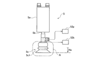
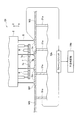
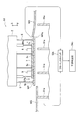
- FIG. 1 is a perspective view showing a processing system ST including a product carry-out device 52 provided with a takeout loader 51 which is an example of a product take-out device according to an embodiment of the present invention.
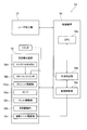
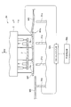
- FIG. 2 is a block diagram showing the configuration of the processing system ST.
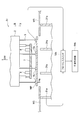
- FIG. 3 is a perspective view showing the takeout loader 51.
- FIG. 4 is a side view showing the suction unit 5 provided in the takeout loader 51.
- FIG. 5 is a partial cross-sectional view for explaining the internal structure of the suction pad portion 5 c provided in the suction unit 5.
- FIG. 6 is a schematic bottom view showing the takeout loader 51. As shown in FIG. FIG. FIG.
- FIG. 7 is a perspective view showing the vibration unit 6 provided in the takeout loader 51.
- FIG. FIG. 8 is a first operation diagram for explaining the product taking out operation by the takeout loader 51.
- FIG. 9 is a second operation diagram for explaining the product taking out operation by the takeout loader 51.
- FIG. 10 is a third operation diagram for explaining the product taking out operation by the takeout loader 51.
- FIG. 11 is a fourth operation diagram for explaining the product taking out operation by the takeout loader 51.
- FIG. FIG. 12 is a fifth operation diagram for explaining the product taking out operation by the takeout loader 51.
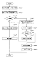
- FIG. 13 is a flowchart for explaining the procedure of the product taking out operation by the takeout loader 51. As shown in FIG.
- the product takeout apparatus will be described using a takeout loader unit 51 as an example thereof, and a laser processing system ST including a product delivery apparatus 52 provided with the takeout loader unit 51 and a laser processing machine 53.
- a takeout loader unit 51 is referred to as a TK unit 51.
- FIG. 1 The entire configuration of the laser processing system ST will be described with reference to FIG. 1 as a perspective view and FIG. 2 as a block diagram.
- FIG. 2 the directions of upper, lower, left, right, front, and back are defined by the arrows in FIG.
- the vertical direction is the vertical direction
- the front is the standing position of the operator.
- the laser processing system ST includes a laser processing machine 53, a product unloading device 52 disposed adjacent to one of the left and right (right side in FIG. 1) of the laser processing machine 53, and a control device 54 for controlling the operation of the entire system. It is comprised including.
- the laser processing machine 53 has a laser oscillator 53a and a laser processing head (not shown) for emitting the laser beam generated by the laser oscillator 53a.
- the laser oscillator is, for example, a fiber laser, and the laser light generated by the laser oscillator 53a is supplied to the laser processing head via the process fiber 53b.
- the laser processing machine 53 also makes it possible to move the work pallet 31 on which the work W is placed in the left-right direction in the processing machine, and allows the laser processing head to move back and forth and up and down. Further, the laser processing machine 53 has a pallet port 53c on the right side in FIG. 1 for moving the work pallet 31 in and out so that the work pallet 31 can be taken in and out from the laser processing machine 53 through the pallet port 53c. .
- FIG. 1 the work pallet 31 discharged from the laser processing machine 53 to the product carry-out device 52 is shown in a state in which the work W (indicated by a dashed line) is placed.
- the laser processing machine 53 can perform laser processing by irradiating the laser beam from the laser processing head to any horizontal position (front, rear, left, and right positions) of the work W placed on the work pallet 31. There is.
- the product carry-out device 52 has a pallet table 52a provided at a position corresponding to the pallet inlet / outlet 53c on the right of the laser processing machine 53, and a transfer table 52b provided in parallel in front of the pallet table 52a. There is. In FIG. 1, the work pallets 31 are shown transported to the pallet table 52a.
- the product carry-out device 52 includes a pair of top frames 52c and 52d supported in a posture extending in parallel to the left and right and in parallel with each other by the plurality of columns 52e and the wall 52f.
- the pair of top frames 52c, 52d is disposed at a position corresponding to the width of the pallet table 52a, and at least in a range corresponding to the longitudinal length of the pallet table 52a and the transfer table 52b, the rails 52g, 52h Is provided.
- a movable frame 52j extending in the left-right direction is supported by the rails 52g, 52h so as to be movable in the front-rear direction (arrow DRa).
- the TK unit 51 is supported by the movable frame 52j so as to be movable in the left-right direction (arrow DRb).
- the product delivery device 52 includes a TK unit drive unit 52m and a pallet drive unit 52n (see FIG. 2).
- the TK unit drive unit 52m executes back and forth movement of the movable frame 52j with respect to the rails 52g and 52h and left and right movement of the TK unit 51 with respect to the movable frame 52j by control of the control device 54.
- the TK unit 51 can move above the arbitrary horizontal position of the pallet table 52a and the transfer table 52b.
- the TK unit 51 includes, at a lower portion thereof, a suction unit 51a having a plurality of suction pads capable of suctioning a plate-like member such as a product. Further, the TK unit 51 includes an elevation drive unit 51b that raises and lowers the suction unit 51a with respect to the movable frame 52j. The operation of the elevation drive unit 51 b is controlled by the control device 54.
- control device 54 is configured to include a central processing unit (CPU) 54a, an interference determination unit 54b, and a vibration control unit 54c.
- CPU central processing unit
- interference determination unit 54b an interference determination unit
- vibration control unit 54c an interference control unit
- the product carry-out device 52 transfers the product WP to the transfer table 52b from the product WP on the work pallet 31 transported from the laser processing machine 53 and the skeleton WS (see FIG. 8) which is the remaining material. be able to.
- the TK unit 51 is moved, positioned above the product WP and lowered.
- the product WP is adsorbed and raised by the suction pad 5c of the suction unit 51a, moved to the upper side of the transfer table 52b by horizontal movement, and then lowered to release the suction.
- the product WP is transferred from the work pallet 31 onto the transfer table 52b.
- the work pallet 31 is a rectangular pallet in which a plurality of skids 31a, which are metal plates having a plurality of pointed protrusions 31a1 pointed upward, are arranged in parallel.
- the workpiece W placed on the workpiece pallet 31 is supported by the plurality of pointed protrusions 31a1.
- the plurality of skids 31a are electrically connected in parallel with the floatless switch 52k (see FIG. 2).
- FIG. 3 is a perspective view of the TK unit 51 as viewed slightly obliquely from the upper right.
- the movable frame 52 j supporting the TK unit 51 is shown by a dashed line.
- the TK unit 51 has a servomotor (not shown) and an elevation drive unit 51b supported by the movable frame 52j, and a pillar-shaped main body which ascends and descends with respect to the movable frame 52j using the servomotor as a power source. 1 and a suction unit 51 a attached to the lower part of the main unit 1.
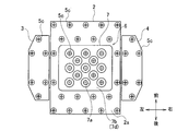
- the suction portion 51a moves between a base position 2 substantially in the shape of a hexahedron, and a base position closely supported by the support arms 3a and 4a and in close contact with the base 2 and an extended position extended leftward and rightward ( Arrow DRc), and a pair of auxiliary parts 3 and 4 are provided.
- the auxiliary portions 3 and 4 in the basic position are indicated by solid lines
- the auxiliary portions 3 and 4 in the extended position are indicated by dashed lines.
- FIG. 4 is a side view showing a single unit of the suction unit 5
- FIG. 5 is a partial cross-sectional view of a portion A in FIG.
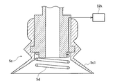
- the suction unit 5 has an air cylinder 5a, a rod 5b contracted from its lower part by the operation of the air cylinder 5a, and a suction pad portion 5c attached to the tip of the rod 5b.
- a pump 52p (see also FIG. 2) for generating a negative pressure is connected to the suction pad portion 5c, and the flat member such as the product WP can be adsorbed by making the inside of the rubber suction portion 5c1 at the tip negative pressure. It is supposed to be.
- the operation of the pump 52p is controlled by the controller 54.
- a coil spring 5d which is made of a conductive material and which can be compressed in the vertical direction is attached.
- the suction pad portion 5c adsorbs the metal plate material, the coil spring 5d is brought into pressure contact with the metal plate material to achieve conduction.
- the coil spring 5d of each of the plurality of suction pad portions 5c is electrically connected in parallel with the floatless switch 52k (see FIG. 2) to function as a contact for detecting conduction.
- the coil spring 5d is also referred to as a contact 5d.
- the floatless switch 52k directs the ON signal to the interference determination unit 54b of the control device 54 when the skid 31a and the contact 5d (the coil spring 5d) do not conduct, and when the floatless switch 52k does not take the conduction. Output.
- the height positions of the suction surfaces of the suction pads are aligned at a predetermined distance Ha below the lower surface of the base 2.
- the suction part 51a only the contact 5d can be conducted to the product WP, and the other part is in an insulated state.
- the base 2 is provided with a vibration unit 6.
- the vibration unit 6 includes a touch plate 7 which is a rectangular resin plate with rounded corners and a tip of a rod 9a connected to the vicinity of the corner of the touch plate 7 And 4 elevating cylinders 9 fixed to the base 2 at the base side.
- the vibration unit 6 has two vibrators 8 (8a, 8b) offset and attached in the lateral direction in the vicinity of the edge portions of the two opposite sides of the touch plate 7.
- the touch plate 7 is provided with openings 7 a through which the respective suction pad portions 5 c at positions overlapping the touch plate 7 are inserted.
- the plurality of elevating cylinders 9 synchronously perform the in / out operation of the rod 9a. That is, the touch plate 7 is lifted and lowered in the horizontal posture by the operation of the lift cylinder 9, and the lifting and lowering operation is controlled by the control device 54. As described above, the lowermost position in the lifting and lowering operation of the touch plate 7 is a position where the lower surface 7 b of the touch plate 7 is a predetermined distance Ha downward from the lower surface 2 a of the base 2.
- the touch plate 7 has a flat portion 7d (FIG. 6) as a flat surface of a predetermined area on at least a part of the lower surface 2a.
- the entire lower surface 2a is a flat portion 7d.
- the flat portion 7 d is moved up and down with the horizontal cylinder 7 operated.
- the vibrator 8 is an air vibrator that generates a vibration with compressed air. More specifically, it is a general-purpose product also called a turbine vibrator that generates vibrations by rotating an impeller with an eccentric weight with compressed air, and is attached to the upper surface 7c of the touch plate 7 by bolts (not shown) .
- the amplitude and the vibration frequency are made variable according to the pressure (for example, 0.2 to 0.6 MPa) of the compressed air supplied, and the variable range of the vibration frequency is about 100 to several hundreds Hz.
- FIG. 8 is a front sectional view including the product WP and the skeleton WS after the product WP is cut out of the work on the skid 31 a by the cutting process of the laser processing machine 53.
- some members such as the suction unit 5 are schematically described.
- the CPU 54a of the control device 54 moves the TK unit 51 above the product WP and then lowers the product WP, and suctions the product WP by the suction pad portion 5c of the suction unit 5 (Step 1).
- the TK unit 51 is raised by a predetermined height Hb (for example, about 30 mm) (FIG. 9: arrow DRf) (Step 2).
- the product WP also rises with the suction pad portion 5c, and if there is no interference with the skeleton WS, as shown in FIG. 9, the product WP rises alone.
- the skeleton WS remains mounted on the skid 31a without rising.
- the interference determination unit 54b of the control device 54 confirms whether the output of the floatless switch 52k is on or off.
- the plurality of skids 31a and the plurality of suction units 5 are connected in parallel to the floatless switch 52k.
- the interference determination unit 54b can determine that the output of the floatless switch 52k is ON / OFF, and that there is conduction / non-conduction (Step 3).
- FIG. 8 shows the case where the product WP is lifted contactlessly to the skeleton WS without interference, so the output of the floatless switch 52k is turned off, and the interference determination unit 54b determines that “no conduction” ( Step 3: NO).
- the CPU 54a raises the TK unit 51 to the uppermost position together with the product WP adsorbing it, on the assumption that no interference occurs between the product WP and the skeleton WS (Step 4).
- Step 5 the product WP is transported and accumulated to a transfer destination such as the transfer table 52b by horizontal movement and subsequent lowering.
- Step 2 is performed in a state where the product WP and the skeleton WS interfere with each other and a part WPa of the product WP overlaps the lower side of the skeleton WS.
- execution of (Step 2) results in the state shown in FIG.
- the skeleton WS is lifted.
- the contact 5d in the suction pad 5c in contact with the product WP and the skid 31a in contact with the skeleton WS are conducted.
- the output of the floatless switch 52k is turned on, and the interference determination unit 54b determines that "there is conduction" (Step 3: YES).
- the vibration control unit 54 c operates the lift cylinder 9 to lower the vibration unit 6 (FIG. 11: arrow DRg) in response to the determination of “conduction”, and the flat surface portion 7 d of the touch plate 7 is the upper surface WPb of the product WP.
- Contact (Step 6).
- the predetermined area of the flat portion 7d in the touch plate 7 is set in advance as an area that can reliably contact other parts even if the product WP has a partially missing part such as a hole.
- the force by which the touch plate 7 pushes the product WP downward is set to be lower than the suction force of the product WP by the suction unit 5. Therefore, the product WP is not released from the suction of the suction unit 5 by the contact of the touch plate 7 and does not fall off.
- the touch plate 7 is formed of a resin, the product WP is not scratched.
- the base material may be a hard material such as a metal material, and the contact portion with the product WP may be formed of resin or rubber softer than metal to avoid damage to the product WP.
- the contact of the touch plate 7 with the product WP is grasped by, for example, the extension amount of the rod 9 a of the lifting and lowering cylinder 9.
- the vibration control unit 54c operates the vibrator 8 for a predetermined time t1 after the flat surface portion 7d of the touch plate 7 contacts the product WP, and applies vibration to the product WP and the skeleton WS contacting at the site WPa. (Step 7).
- the two vibrators 8a and 8b as the vibrator 8 apply, to the touch plate 7, a reciprocating motion with a minute amplitude generated at, for example, about 100 to several hundreds Hz.
- the predetermined time t1 is set in advance. For example, 2 to 3 seconds.
- the interference determination unit 54b determines whether the product WP and the skeleton WS are conductive based on whether the signal from the floatless switch 52k is on or off (Step 8).
- the product WP is given a minute vibration generated by each of the vibrators 8a and 8b, and the relative position with the skeleton WS changes. In many cases, this reduces the degree of interference and cancels the interference.
- the vibrators 8a and 8b operate in a state in which the product WP is lifted to a predetermined height by the execution of (Step 2), the interfering skeleton WS is not lifted only partially by the site WPa. It is in a stable state.
- the interference determination unit 54b determines that there is continuity (Yes) in (Step 8)
- the CPU 54a cancels the suction of the product WP by the suction pad unit 5c, assuming that the interference is not eliminated and a defect state is occurring. Release the WP (Step 9).
- the CPU 54a outputs an alarm by voice or image from an output unit (not shown) (Step 10).
- the interference determination unit 54b determines that there is no conduction (No) in (Step 8)
- the CPU 54a determines that the interference between the product WP and the skeleton WS has been eliminated and the product WP is in a separated good condition.
- the control unit 54c raises the vibration unit 6 to separate the touch plate 7 from the product WP (Step 11). Then, the process proceeds to (Step 4) to execute the above-described product conveyance.
- the process may return to (Step 7), operate the vibrators 8a and 8b again, and apply vibration to the product WP and the interfering skeleton WS.
- a determination step of whether or not vibration application has reached a predetermined number of times is provided between (Step 8) and (Step 9), and vibration is continuously applied when it is determined in (Step 8) that conduction is present.
- the operation may be set to repeat up to a predetermined number of upper limits.
- the processing efficiency per product is reduced by the vibration operation time, the probability that the product WP and the skeleton WS get stuck (interference) increases. Therefore, the number of alarm occurrences may be reduced, and the efficiency of the entire processing operation may be improved.
- the number of vibration applying operations may be appropriately set according to the degree of occurrence of the interference.
- the number of vibrators 8 installed on the touch plate 7 may be one, two as described above, or three or more.
- the touch plates 7 be provided at random positions as much as possible.
- the vibrator may be installed at a position deviated in the left and right direction near the edge facing in the front and rear direction of the touch plate 7.
- the vibration mode generated in the touch plate 7 becomes irregular, and the overlapping which is the interference between the product WP and the skeleton WS is resolved better and in a short time .
- the vibration of the vibrator 8 causes the touch plate 7 not to move in one direction but to reciprocate and to reciprocate by minute displacement, so that the variation is offset even at the point of displacement, and adsorption by the adsorption pad portion 5c The impact on it can be ignored.
- the laser processing machine 53 is a laser complex processing machine
- punching is performed by punching to expand the cutting width along the outer shape, and product WP and skeleton WS It was also done to avoid interference.
- the embodiments of the present invention are not limited to the above-described configurations and procedures, and may be modified within the scope of the present invention.
- the shape and size of the touch plate 7 are not limited. It may be appropriately set according to the shape of the product WP, and the type of the vibrator 8 is not limited. Not limited to the above-described air type, it may be an electric type.
- the predetermined height Hb to be raised in (Step 2) is preferably set to a small size in accordance with the thickness of the work W, that is, the thickness of the product WP and the thickness of the skeleton WS.
- the skeleton WS is less likely to be deformed and the deformation resistance is increased. Therefore, in the suction rise of the product WP when the product WP and the skeleton WS interfere with each other, the thicker the plate thickness, the larger the deformation resistance received from the skeleton WS, and the product WP may fall off the suction pad 5c. is there.
- the predetermined height Hb which is the rising height of the product WP in (Step 2), to be smaller as the thickness is larger.
- the outer edge position which interferes with the skeleton WS is farther from the suction portion 51a, and the moment of resistance received from the skeleton WS becomes larger, which is disadvantageous to the suction.
- Step 2 it is desirable to set the predetermined height Hb in (Step 2) smaller as the product WP is larger, and to reduce the moment of resistance received from the skeleton WS.
- the touch plate 7 is not limited to one that contacts the upper surface of the product WP, but may be one that rises from the work pallet 31 side and contacts the lower surface.
- the product WP is not limited to one that has been cut by laser light. It may be cut by a thermal cutting device other than a laser or a punch processing machine.
Landscapes
- Engineering & Computer Science (AREA)
- Mechanical Engineering (AREA)
- Laser Beam Processing (AREA)
- Feeding Of Workpieces (AREA)
- Manipulator (AREA)
- Sheets, Magazines, And Separation Thereof (AREA)
Abstract
製品取り出し装置は、金属板状の製品(WP)を吸着して上昇する吸着部(51a)と、吸着部(51a)で吸着している製品(WP)に対し、離隔する位置と接触する位置との間で移動するタッチプレート(7)と、タッチプレート(7)を振動させるバイブレータ(8)とを備える。
Description
本発明は、製品取り出し装置,製品搬出装置,及び製品取り出し方法に係り、特に、ワークから切り出した製品をワーク残材(スケルトン)から分離して取り出す製品取り出し装置,製品搬出装置,及び製品取り出し方法に関する。
日本国特許公開公報特開2005-272118号(特許文献1)には、板材製品をパンチ加工で打ち抜いて取り出す際の、ワーク残材(スケルトン)からの分離技術について記載されている。
特許文献1に記載された分離技術は、製品の外形とスケルトンの内形とをわずかに噛み合わせて摩擦力により切り離されない一体化状態としておき、分離の際に打撃を加え、その打撃振動で両者を分離するものである。
製品のスケルトンからの分離は、特許文献1に記載されたようなプレス加工に限らず、レーザ光による切断加工でも同様に行われる。
例えば、レーザ加工とパンチ加工とを実行可能なレーザ複合加工機を用いた加工では、多くの場合、製品は、外形がレーザ光で切断されて切り出される。そして、切り出された製品は、テイクアウトローダの吸着装置で吸着して隣接設置された棚などに搬出集積される。
しかしながら、レーザ切断加工における切断幅(カーフ幅)は比較的狭く、加工中或いは加工後に製品の一部がスケルトンの下側にもぐり込んだり、或いは、加工に伴う発熱で切断部位近傍に歪みが生じ、その歪み具合によっては製品とスケルトンとが僅かに上下方向に重なってしまう場合があった。
製品がスケルトンの下側に重なると、テイクアウトローダの吸着装置で製品を吸着上昇させた際にスケルトンが干渉し、製品の上昇分離に不具合が生じる。
特許文献1に記載された打撃による分離技術では、外形と内形の摩擦による一体化状態の解消に対しては有効であるものの、製品とスケルトンとの上下方向の重なりの解消は難しい。
そのため、ワークから切り出された製品を取り出す際の、スケルトンに対する上昇分離を良好に行える工夫が望まれていた。
本発明によれば、スケルトンに対する製品の上昇分離を良好に行うことができる製品取り出し装置,製品搬出装置,及び製品取り出し方法を提供することができる。
本発明の技術的側面によれば、製品取り出し装置は、金属板状の製品を吸着して上昇する吸着部と、前記吸着部で吸着している前記製品に対し、離隔する位置と接触する位置との間で移動するタッチプレートと、前記タッチプレートを振動させるバイブレータとを備えることを特徴とする。
他の技術的側面によれば、製品搬出装置は、金属板状のワークから切り出された製品及び残材であるスケルトンを支持する支持部材を有するパレットと、前記支持部材に支持された前記製品を吸着して上昇する吸着部と、前記吸着部で吸着している前記製品に対し、離隔する位置と接触する位置との間で移動するタッチプレートと、前記タッチプレートを振動させるバイブレータと、前記吸着部を、前記支持部材に支持された前記製品を吸着して所定距離上昇させた後に、前記タッチプレートを前記吸着部が吸着している前記製品に接触させると共に前記バイブレータを所定時間だけ動作させるよう制御する制御装置とを備えることを特徴とする。
また、製品取り出し方法は、支持部材に支持された、金属板から切り出された製品及び残材であるスケルトンから前記製品を、吸着部により吸着して上昇する吸着上昇ステップと、前記吸着部で吸着している前記製品に対し、タッチプレートを接触させる接触ステップと、バイブレータによって前記製品に接触している前記タッチプレートを振動させる振動付与ステップとを含むことを特徴とする。
本発明の実施の形態に係る製品取り出し装置を、その実施例であるテイクアウトローダユニット51と、テイクアウトローダユニット51を備えた製品搬出装置52及びレーザ加工機53を含むレーザ加工システムSTと、により説明する。以下、テイクアウトローダユニット51をTKユニット51と称する。
(実施例)
レーザ加工システムSTの全体構成について、斜視図である図1及びブロック図である図2を参照して説明する。説明の便宜上、上下左右前後の各方向を図1の矢印で規定する。上下方向は鉛直方向であり、前方は作業者の立ち位置側である。
レーザ加工システムSTの全体構成について、斜視図である図1及びブロック図である図2を参照して説明する。説明の便宜上、上下左右前後の各方向を図1の矢印で規定する。上下方向は鉛直方向であり、前方は作業者の立ち位置側である。
レーザ加工システムSTは、レーザ加工機53と、レーザ加工機53の左右いずれか(図1では右側)に隣接配置された製品搬出装置52と、システム全体の動作を制御する制御装置54と、を含んで構成されている。
レーザ加工機53は、レーザ発振器53aと、レーザ発振器53aで生成されたレーザ光を出射するレーザ加工ヘッド(不図示)とを有する。レーザ発振器は、例えばファイバレーザであり、レーザ発振器53aで生成されたレーザ光は、プロセスファイバ53bを介してレーザ加工ヘッドに供給される。
レーザ加工機53は、また、ワークWを載置したワークパレット31を加工機内で左右方向に移動可能にすると共に、レーザ加工ヘッドを前後及び上下方向に移動可能としている。 また、レーザ加工機53は、図1における右側面に、ワークパレット31を出入りさせるパレット出入口53cを有し、レーザ加工機53の内外にパレット出入口53cを通してワークパレット31を出し入れできるようになっている。図1では、レーザ加工機53から製品搬出装置52側に排出されたワークパレット31が、ワークW(鎖線記載)を載置した状態で示されている。
このように、レーザ加工機53は、ワークパレット31に載置されたワークWの任意の水平位置(前後左右位置)に対しレーザ加工ヘッドからレーザ光を照射してレーザ加工を行えるようになっている。
製品搬出装置52は、レーザ加工機53の右隣におけるパレット出入口53cに対応した位置に備えられたパレットテーブル52aと、パレットテーブル52aの前方に並設された移し替えテーブル52bと、を有している。図1において、ワークパレット31は、パレットテーブル52aに移送された状態で示されている。
さらに、製品搬出装置52は、複数の支柱52e及び壁部52fによって、左右に離隔し前後に平行延在する姿勢で支持された一対のトップフレーム52c,52dを備えている。
一対のトップフレーム52c,52dは、パレットテーブル52aの幅に対応した位置に配設されており、少なくともパレットテーブル52a及び移し替えテーブル52bの前後方向長さに対応した範囲それぞれに、レール52g,52hが設けられている。 レール52g,52hには、左右方向に延びる可動フレーム52jが前後方向に移動可能(矢印DRa)に支持されている。
可動フレーム52jには、TKユニット51が左右方向に移動可能(矢印DRb)に支持されている。
製品搬出装置52は、TKユニット駆動部52m及びパレット駆動部52n(図2参照)を備えている。TKユニット駆動部52mは、レール52g,52hに対する可動フレーム52jの前後移動、及び可動フレーム52jに対するTKユニット51の左右移動を、制御装置54の制御によって実行する。
TKユニット駆動部52mの動作により、TKユニット51は、パレットテーブル52a及び移し替えテーブル52bの任意水平位置の上方に移動可能である。
TKユニット51は、下部に、製品などの板状部材を吸着可能な吸着パッドを複数有する吸着部51aを備える。また、TKユニット51は、可動フレーム52jに対し吸着部51aを昇降させる昇降駆動部51bを有している。昇降駆動部51bの動作は、制御装置54によって制御される。
図2に示されるように、制御装置54は、中央処理装置(CPU)54a,干渉判定部54b,及び振動制御部54cを含んで構成されている。
以上の構成により、製品搬出装置52は、レーザ加工機53から搬送されたワークパレット31上の製品WP及び残材であるスケルトンWS(図8参照)から、製品WPを移し替えテーブル52bに移送させることができる。
具体的には、TKユニット51を移動し、製品WPの上方に位置させて下降させる。次いで、吸着部51aの吸着パッド部5cによって製品WPを吸着して上昇させ、水平移動により移し替えテーブル52bの上方に移動した後、下降して吸着を解除する。 これにより、製品WPは、ワークパレット31上から移し替えテーブル52b上に移送される。
図1に示されるように、ワークパレット31は、上方に尖った複数の尖突部31a1を有する金属板であるスキッド31aを複数枚並設した矩形のパレットである。ワークパレット31に載置されたワークWは、複数の尖突部31a1によって支持される。複数のスキッド31aは、フロートレススイッチ52k(図2参照)と、電気的に並列接続される。
次に、TKユニット51を、図3~図7を参照して説明する。図3は、TKユニット51を前方わずかに右斜め上方から見た斜視図である。TKユニット51を支持する可動フレーム52jは、鎖線で示されている。
TKユニット51は、サーボモータ(不図示)を有し可動フレーム52jに支持された昇降駆動部51bと、昇降駆動部51bに対しサーボモータを動力源として可動フレーム52jに対し昇降する柱状の本体部1と、本体部1の下部に取り付けられた吸着部51aとを有する。
吸着部51aは、概ね六面体形状の基部2と、左右それぞれ支持腕部3a,4aに支持されて基部2に密着した基本位置と左方及び右方に張り出した張り出し位置との間で移動する(矢印DRc参照)、一対の補助部3,4と、を備えている。図2では、基本位置にある補助部3,4を実線で、張り出し位置にある補助部3,4を鎖線で示している。
基部2及び補助部3,4の下部には、吸着ユニット5が上下方向を軸として複数配置されている。図4は、吸着ユニット5の単体を示す側面図であり、図5は、図4におけるA部の部分断面図である。
吸着ユニット5は、エアシリンダ5aと、エアシリンダ5aの動作によりその下部から延縮するロッド5bと、ロッド5bの先端に取り付けられた吸着パッド部5cと、を有する。
吸着パッド部5cには、負圧を発生するポンプ52p(図2も参照)が接続されており、先端のゴム製の吸盤部5c1の内部を負圧にして製品WPなどの平板部材を吸着できるようになっている。ポンプ52pの動作は制御装置54により制御される。
図5に示されるように、吸着パッド部5cの内部には、導電材で形成され上下方向に圧縮可能なコイルばね5dが取り付けられている。コイルばね5dは、吸着パッド部5cが金属板材を吸着したときに、その金属板材に押圧接触して導通が図られる。
複数の吸着パッド部5cそれぞれのコイルばね5dは、フロートレススイッチ52k(図2参照)と電気的に並列接続されて、導通検出のための接触子として機能する。以下、コイルばね5dを接触子5dとも称する。
フロートレススイッチ52kは、スキッド31aと接触子5d(コイルばね5d)との間に導通が取れている場合にON信号を、取れていない場合にOFF信号を制御装置54の干渉判定部54bに向け出力する。
図3に示されるように、複数の吸着ユニット5は、各吸着パッド吸着面の高さ位置が、基部2の下面から下方に所定距離Haとなる位置で揃うようになっている。吸着部51aは、製品WPに対し、接触子5dのみ導通可能として他の部位は絶縁状態とされている。
また、基部2には、振動ユニット6が備えられている。図6及び図7に示されるように、振動ユニット6は、角にR付された矩形の樹脂板であるタッチプレート7と、タッチプレート7の角部近傍それぞれにロッド9aの先端が連結され本体根本側が基部2に固定された4つの昇降シリンダ9と、を有する。また、振動ユニット6は、タッチプレート7の対向する二辺の縁部近傍において、左右方向にずれて取り付けられた二つのバイブレータ8(8a,8b)とを有する。タッチプレート7には、タッチプレート7と重なる位置にある吸着パッド部5cそれぞれを挿通させる開口部7aが設けられている。
複数の昇降シリンダ9は、ロッド9aの出入り動作を同調して行う。すなわち、タッチプレート7は、昇降シリンダ9の動作により水平姿勢のまま昇降し、この昇降動作は制御装置54によって制御される。タッチプレート7の昇降動作における最下位置は、既述のように、タッチプレート7の下面7bが、基部2の下面2aから下方に所定距離Haとなる位置とされる。
タッチプレート7は、下面2aの少なくとも一部に、所定の面積の平面として平面部7d(図6)を有している。この例では、下面2a全体が平面部7dとなっている。タッチプレート7は、昇降シリンダ9の動作によって平面部7dが水平を維持して昇降する。
バイブレータ8は、圧縮空気で振動を発生するエアバイブレータである。より詳しくは、偏心錘の付いた羽根車を圧縮空気で回転させることにより振動を発生するタービンバイブレータとも称される汎用品であり、不図示のボルトによってタッチプレート7の上面7cに取り付けられている。供給する圧縮空気の圧力(例えば0.2~0.6MPa)に応じ、振幅及び振動周波数が可変とされ、振動周波数の可変範囲は約100~数百Hzである。
以上詳述したレーザ加工システムSTの製品搬出装置52における、スケルトンWSに対する製品WPの取り出し手順について、図8~図12の模式図及び図13のフロー図を主に参照して説明する。まず、図8,図9,及び図13を参照して、製品WPがスケルトンWSとの干渉なく取り出せる場合について説明する。
図8は、レーザ加工機53の切断加工によってスキッド31a上のワークから製品WPを切り出した後の、製品WPとスケルトンWSとを含む前方視断面図である。図8において、吸着ユニット5など一部の部材は模式的に記載してある。
まず、切断加工が終了したら、制御装置54のCPU54aは、TKユニット51を製品WPの上方に移動後下降させ、吸着ユニット5の吸着パッド部5cで製品WPを吸着する(Step1)。
吸着パッド部5cで製品WPを吸着したら、TKユニット51を所定の高さHb(例えば30mm程度)上昇させる(図9:矢印DRf)(Step2)。
これにより、吸着パッド部5cと共に製品WPも上昇しようとして、スケルトンWSとの干渉がない場合には、図9に示されるように、製品WPは単独で上昇する。一方、スケルトンWSはスキッド31a上に浮き上がり無く載置されたままとなる。
次に、制御装置54の干渉判定部54bは、フロートレススイッチ52kの出力がオン/オフのいずれであるかを確認する。
図9及び既述のように、フロートレススイッチ52kには、複数のスキッド31a及び複数の吸着ユニット5がそれぞれ並列に接続されている。
従って、製品WPとスケルトンWSとが一箇所でも接触して導通していると、接触子5dとスキッド31aとの間の導通がとれてフロートレススイッチ52kの出力がオンになる。一方、製品WPとスケルトンWSとが非接触で導通がとれていない場合、フロートレススイッチ52kの出力はオフとなる。これにより、干渉判定部54bは、フロートレススイッチ52kの出力のオン/オフで、それぞれ導通あり/導通なしと判定できる(Step3)。
図8は、製品WPがスケルトンWSに対し干渉なく非接触で持ち上げられた場合が示されているので、フロートレススイッチ52kの出力はオフとなり、干渉判定部54bは「導通なし」と判定する(Step3:NO)。
この「導通なし」判定を受け、CPU54aは、製品WPとスケルトンWSとの干渉が生じていないとして、TKユニット51を吸着している製品WPと共に最上位置まで上昇させる(Step4)。
次いで、製品WPを、水平移動及びその後の下降によって移し替えテーブル52bなどの移送先に搬送、集積する(Step5)。
次に、製品WPとスケルトンWSとが干渉し、製品WPの一部の部位WPaがスケルトンWSの下側に重なっている状態で(Step2)を実行した場合を説明する。この場合、(Step2)の実行により図10に示される状態となる。
すなわち、製品WPの部位WPaにおいて、スケルトンWSが持ち上げられている状態である。この場合、部位WPaがスケルトンWSと接触しているため、製品WPに接触している吸着パッド部5c内の接触子5dと、スケルトンWSに接触しているスキッド31aと、が導通する。これにより、フロートレススイッチ52kの出力がオンとなるので、干渉判定部54bは「導通あり」と判定する(Step3:YES)。
この「導通あり」の判定を受け、振動制御部54cは、昇降シリンダ9を動作させて振動ユニット6を下降させ(図11:矢印DRg)、タッチプレート7の平面部7dを製品WPの上面WPbに接触させる(Step6)。タッチプレート7における平面部7dの所定の面積は、製品WPが孔などの部分的に欠落した部分を有していても、他の部分に確実に接触できる面積として予め設定される。
タッチプレート7が製品WPを下方へ押す力は、吸着ユニット5による製品WPの吸着力を下回るように設定されている。従って、製品WPは、タッチプレート7の接触で吸着ユニット5の吸着から開放されて脱落してしまうことはない。
また、タッチプレート7は、樹脂で形成されているので、製品WPに傷を付けることはない。もちろん、基材を金属材などの硬質材とし製品WPとの接触部位を金属より柔らかい樹脂やゴムなどで形成して製品WPへの傷付きを回避してもよい。
タッチプレート7の製品WPへの接触は、例えば昇降シリンダ9のロッド9aの延び出し量などで把握される。
振動制御部54cは、タッチプレート7の平面部7dが製品WPに接触した後、バイブレータ8を所定の時間t1だけ動作させ、製品WP及びその部位WPaで接触しているスケルトンWSに振動を付与する(Step7)。
バイブレータ8としての二つのバイブレータ8a,8bは、既述のように、例えば、100~数百Hz程度で発生した微小振幅の往復動を、タッチプレート7に対し付与するものである。所定の時間t1は予め設定しておく。例えば、2~3秒とする。
バイブレータ8a,8bの時間t1の動作後、干渉判定部54bは、フロートレススイッチ52kからの信号がオンかオフかに基づいて、製品WPとスケルトンWSとの導通有無を判定する(Step8)。
製品WPには、バイブレータ8a,8bそれぞれが発生する微小振動が付与されて、スケルトンWSとの相対位置が変化する。これにより、多くの場合、干渉程度が低減して干渉が解消される。
特に、バイブレータ8a,8bが動作するのが、製品WPが(Step2)の実行により所定の高さに持ち上げられた状態であるため、干渉するスケルトンWSは部位WPaによって一部のみが持ち上げられた不安定な状態にある。
不安定な状態の物体に微小振動が付与されると、安定状態へ移行しようとする場合が多いことから、スケルトンWSは、振動の付与により、部位WPaにより部分的に持ち上げられた不安定な状態から全体がスキッド31a上に支持された安定状態へ移行しようとするので、製品WPとの干渉が解消する傾向にある。
(Step8)において、干渉判定部54bが、導通有り(Yes)と判定したら、CPU54aは、干渉が解消されてなく不良状態が生じているとして、吸着パッド部5cによる製品WPの吸着を解除し製品WPを開放する(Step9)。
次いで、CPU54aは、不図示の出力部からアラームを音声又は画像により出力する(Step10)。
一方、(Step8)において、干渉判定部54bが、導通無し(No)と判定したら、CPU54aは、製品WPとスケルトンWSとの干渉が解消され製品WPは切り離された良好状態になったとして、振動制御部54cは、振動ユニット6を上昇させてタッチプレート7を製品WPから離隔させる(Step11)。そして、(Step4)に移行し、既述の製品搬送を実行する。
(Step8)で干渉判定部54bが導通有りと判定した場合、(Step7)へ戻り、再度バイブレータ8a,8bを動作させて、製品WP及び干渉しているスケルトンWSに振動を付与してもよい。
すなわち、(Step8)と(Step9)との間に、振動付与が予め定めた所定回数に達したか否かの判定ステップを設け、(Step8)で導通有りとの判定が続いた場合に振動付与動作を所定回数の上限まで繰り返すように設定してもよい。
これにより、振動の動作時間の分、製品一個あたりの加工効率が低下するものの、製品WPとスケルトンWSとの引っ掛かり(干渉)が解消する確率は上昇する。そのため、アラーム発生回数が減って、加工作業全体の効率は向上する場合もあり、振動付与動作の回数は、干渉の発生具合に応じて適宜設定するとよい。
タッチプレート7に設置するバイブレータ8は、一つでもよく、上述のように2個であってもよく、3個以上であってもよい。
バイブレータ8を複数設置する場合は、タッチプレート7において、できるだけランダムな位置に設置することが望ましい。上述のバイブレータ8a,8bの2個の場合は、タッチプレート7の前後方向に対向する縁部近傍の左右方向にはずれた位置に設置するとよい。
バイブレータ7を少なくとも二つの複数個設置することにより、タッチプレート7に生じる振動様式が不規則となって、製品WPとスケルトンWSとの干渉である重なりが、より良好に、かつ短時間に解消する。
また、バイブレータ8により振動するタッチプレート7の振動は微小であるから、吸着パッド部5cによる製品WPの吸着力への影響は無視できる。
また、バイブレータ8の振動により、タッチプレート7は一方方向への移動ではなく、往復動をし、しかも微小変位の往復動となるので、変位の点でも変動が相殺され、吸着パッド部5cによる吸着への影響は無視できる。
また、レーザ加工機53がレーザ複合加工機の場合、従来、レーザ光による製品外形加工後に、その外形に沿って切断幅を拡張する孔明けをパンチ加工で行って、製品WPとスケルトンWSとの干渉を回避することも行われていた。
この場合、稼働効率が落ちコストアップになるという問題があったが、上述の製品搬出装置52を用いれば、レーザ加工後のパンチ加工を行うことなく、良好に製品WPのスケルトンWSからの分離上昇を行うことができる。そのため、パンチ加工を実施する場合と比べて稼働効率が大幅に良化しコストアップが抑制される。
本発明の実施例は、上述した構成及び手順に限定されるものではなく、本発明の要旨を逸脱しない範囲において変形例としてもよい。タッチプレート7の形状及びサイズは限定されるものではない。製品WPの形状に応じて適宜設定してよい、また、バイブレータ8の種類も限定されない。上述のエアー式に限らず電気式であってもよい。
(Step2)で上昇させる所定の高さHbは、ワークWの板厚、すなわち製品WP及びスケルトンWSの板厚の大小に応じて小大に設定することが好ましい。
例えば、スケルトンWSは、板厚が厚いほど変形しにくく変形抵抗が大きくなる。そのため、製品WPとスケルトンWSとが干渉していた場合の製品WPの吸着上昇において、板厚が厚いほどスケルトンWSから受ける変形抵抗が大きく、製品WPが吸着パッド部5cから脱落してしまう虞もある。
そこで、板厚が厚いほど、(Step2)における製品WPの上昇高さである所定の高さHbを小さく設定することは望ましい。
また、製品WPが大きいほど、スケルトンWSと干渉する外縁位置が吸着部51aから遠く、スケルトンWSから受ける抵抗のモーメントが大きくなるため吸着に不利となる。
そこで、製品WPが大きいほど、(Step2)における所定の高さHbを小さく設定して、スケルトンWSから受ける抵抗のモーメントを小さくすることは望ましい。
タッチプレート7は、製品WPの上面に接触するものに限定されず、ワークパレット31側から上昇して下面に接触するものであってもよい。
製品WPは、レーザ光により外形切断されたものに限定されない。レーザ以外の熱切断装置や、パンチ加工機で外形切断されたものであってもよい。
本発明によれば、スケルトンに対する製品の上昇分離を良好に行うことができる、という効果が得られる。
(米国指定)
本国際特許出願は米国指定に関し、2017年11月9日に出願された日本国特許出願第2017-216316号について米国特許法第119条(a)に基づく優先権の利益を援用し、当該開示内容を引用する。
本国際特許出願は米国指定に関し、2017年11月9日に出願された日本国特許出願第2017-216316号について米国特許法第119条(a)に基づく優先権の利益を援用し、当該開示内容を引用する。
Claims (10)
- 金属板状の製品を吸着して上昇する吸着部と、
前記吸着部で吸着している前記製品に対し、離隔する位置と接触する位置との間で移動するタッチプレートと、
前記タッチプレートを振動させるバイブレータとを具備することを特徴とする製品取り出し装置。 - 前記吸着部は、吸着した前記製品と導通する接触子を有することを特徴とする請求項1記載の製品取り出し装置。
- 前記タッチプレートは、下面に平面部を有することを特徴とする請求項1又は請求項2記載の製品取り出し装置。
- 前記バイブレータは、供給する圧縮空気の圧力に応じた振動数で振動するエアバイブレータであることを特徴とする請求項1~3のいずれか1項に記載の製品取り出し装置。
- 前記バイブレータは、少なくとも二つ備えられていることを特徴とする請求項1~4のいずれか1項に記載の製品取り出し装置。
- 金属板状のワークから切り出された製品及び残材であるスケルトンを支持する支持部材を有するパレットと、
前記支持部材に支持された前記製品を吸着して上昇する吸着部と、
前記吸着部で吸着している前記製品に対し、離隔する位置と接触する位置との間で移動するタッチプレートと、
前記タッチプレートを振動させるバイブレータと、
前記吸着部を、前記支持部材に支持された前記製品を吸着して所定距離上昇させた後に、前記タッチプレートを前記吸着部が吸着している前記製品に接触させると共に前記バイブレータを所定時間だけ動作させるよう制御する制御装置と、
を具備することを特徴とする製品搬出装置。 - 前記支持部材は、支持している前記スケルトンと導通し、
前記吸着部は、吸着している前記製品と導通する接触子を有し、
前記制御装置は、前記支持部材と前記接触子との間の導通有無に基づいて前記バイブレータの動作を制御することを特徴とする請求項6記載の製品搬出装置。 - 前記バイブレータは、供給する圧縮空気の圧力に応じた振動数で振動するエアバイブレータであって、
前記制御装置は、前記バイブレータを動作させる前記所定時間の間に前記圧力を変化させることを特徴とする請求項6又は請求項7記載の製品搬出装置。 - 支持部材に支持された、金属板から切り出された製品及び残材であるスケルトンから前記製品を、吸着部により吸着して上昇する吸着上昇ステップと、
前記吸着部で吸着している前記製品に対し、タッチプレートを接触させる接触ステップと、
バイブレータによって前記製品に接触している前記タッチプレートを振動させる振動付与ステップと、
を含むことを特徴とする製品取り出し方法。 - 前記吸着部が吸着している前記製品と導通する接触子を設けておき、
前記吸着部が前記製品を吸着して上昇した後に、
前記接触子と、前記スケルトンを支持している前記支持部材と、の間の導通有無を把握する導通有無把握ステップを含み、
前記導通有無把握ステップで導通有りと把握された場合に、前記タッチプレートを前記製品に接触させると共に前記バイブレータを振動させることを特徴とする請求項9記載の製品取り出し方法。
Priority Applications (3)
| Application Number | Priority Date | Filing Date | Title |
|---|---|---|---|
| EP18875340.4A EP3708524B1 (en) | 2017-11-09 | 2018-11-08 | Product taking out device, product carrying out device, and product taking out method |
| CN201880072345.4A CN111601762A (zh) | 2017-11-09 | 2018-11-08 | 制品取出装置、制品搬出装置以及制品取出方法 |
| US16/761,585 US11001458B2 (en) | 2017-11-09 | 2018-11-08 | Product taking-out apparatus, product carrying-out apparatus, and product taking-out method |
Applications Claiming Priority (2)
| Application Number | Priority Date | Filing Date | Title |
|---|---|---|---|
| JP2017-216316 | 2017-11-09 | ||
| JP2017216316A JP6535066B2 (ja) | 2017-11-09 | 2017-11-09 | 製品取り出し装置,製品搬出装置,及び製品取り出し方法 |
Publications (1)
| Publication Number | Publication Date |
|---|---|
| WO2019093408A1 true WO2019093408A1 (ja) | 2019-05-16 |
Family
ID=66437909
Family Applications (1)
| Application Number | Title | Priority Date | Filing Date |
|---|---|---|---|
| PCT/JP2018/041440 WO2019093408A1 (ja) | 2017-11-09 | 2018-11-08 | 製品取り出し装置,製品搬出装置,及び製品取り出し方法 |
Country Status (5)
| Country | Link |
|---|---|
| US (1) | US11001458B2 (ja) |
| EP (1) | EP3708524B1 (ja) |
| JP (1) | JP6535066B2 (ja) |
| CN (1) | CN111601762A (ja) |
| WO (1) | WO2019093408A1 (ja) |
Families Citing this family (3)
| Publication number | Priority date | Publication date | Assignee | Title |
|---|---|---|---|---|
| CN108367450B (zh) * | 2015-12-18 | 2021-04-02 | 村田机械株式会社 | 工件输送系统以及工件输送方法 |
| JP7156067B2 (ja) * | 2019-02-07 | 2022-10-19 | トヨタ自動車株式会社 | 把持誤差補正方法、装置、及び、プログラム |
| JP7460383B2 (ja) | 2020-02-10 | 2024-04-02 | コマツ産機株式会社 | 取り出し装置のための制御システムおよび制御方法 |
Citations (8)
| Publication number | Priority date | Publication date | Assignee | Title |
|---|---|---|---|---|
| JPS5991216U (ja) * | 1982-12-10 | 1984-06-20 | 三菱自動車工業株式会社 | 加振装置 |
| WO1994001355A1 (en) * | 1992-07-13 | 1994-01-20 | Finn-Power International, Inc. | Apparatus and method for enhancing worksheet separation |
| JP2748424B2 (ja) * | 1988-08-26 | 1998-05-06 | ソニー株式会社 | 内部磁気シールド自動供給装置 |
| JP2571253Y2 (ja) * | 1992-06-30 | 1998-05-18 | 鋼管ドラム株式会社 | 板状部材搬出装置 |
| JP2862999B2 (ja) * | 1990-11-30 | 1999-03-03 | 富士通株式会社 | リードフレームのピックアップ機構 |
| JP2005272118A (ja) | 2004-03-26 | 2005-10-06 | Daiichi Kinzoku Kk | プレス製品分離機 |
| JP2013184805A (ja) * | 2012-03-09 | 2013-09-19 | Amada Co Ltd | 製品分離方法及び装置並びにスケルトン台車 |
| JP2017216316A (ja) | 2016-05-31 | 2017-12-07 | 京セラディスプレイ株式会社 | 光プリンタヘッド |
Family Cites Families (18)
| Publication number | Priority date | Publication date | Assignee | Title |
|---|---|---|---|---|
| JPS5486173A (en) * | 1977-12-19 | 1979-07-09 | Fuji Electric Co Ltd | One sheet extracting separator of laminated board material |
| JPS6486173A (en) | 1987-06-19 | 1989-03-30 | Konishiroku Photo Ind | Color image forming device |
| JP2571253B2 (ja) * | 1988-02-04 | 1997-01-16 | 東京電力株式会社 | 蓄熱冷暖房装置の製氷熱交換器 |
| JPH06127716A (ja) | 1992-10-16 | 1994-05-10 | Mitsubishi Kasei Corp | 薄層シ−トのハンドリング装置 |
| US5676364A (en) * | 1994-08-19 | 1997-10-14 | Amada Company, Limited | Plate material separating apparatus |
| JP4072227B2 (ja) | 1997-01-20 | 2008-04-09 | 株式会社アマダ | 板材搬入出装置 |
| EP1014241B1 (en) * | 1998-12-25 | 2005-03-16 | Yamazaki Mazak Kabushiki Kaisha | Parts classification unit |
| US6606531B1 (en) * | 2002-02-07 | 2003-08-12 | Trumpf, Inc. | Sheet material loader/unloader for machine tools |
| JP4323129B2 (ja) * | 2002-02-15 | 2009-09-02 | 株式会社ディスコ | 板状物の搬送機構 |
| KR100507072B1 (ko) | 2002-07-08 | 2005-08-08 | 현대자동차주식회사 | 패널 이송용 어탯치먼트 |
| JP4935442B2 (ja) | 2007-03-16 | 2012-05-23 | 村田機械株式会社 | 板材搬出装置および板材搬出方法 |
| CN101830356A (zh) * | 2009-03-11 | 2010-09-15 | 中茂电子(深圳)有限公司 | 抵触式分离设备 |
| DE102010040686B3 (de) | 2010-09-14 | 2012-01-05 | Trumpf Werkzeugmaschinen Gmbh + Co. Kg | Elektrische Überwachung von Sauggreifern |
| DE102011106214A1 (de) * | 2011-06-07 | 2012-12-13 | Brötje-Automation GmbH | Endeffektor |
| US8985936B2 (en) * | 2012-09-11 | 2015-03-24 | Nidec Minster Corporation | Method and apparatus for orienting a lamination |
| TWI505981B (zh) | 2014-01-02 | 2015-11-01 | All Ring Tech Co Ltd | Material to undertake positioning device |
| JP6309371B2 (ja) | 2014-07-01 | 2018-04-11 | 株式会社ディスコ | 板状ワークの搬出方法 |
| CN205222063U (zh) | 2015-12-22 | 2016-05-11 | 苏州晟成光伏设备有限公司 | 一种自动吸玻璃装置 |
-
2017
- 2017-11-09 JP JP2017216316A patent/JP6535066B2/ja active Active
-
2018
- 2018-11-08 US US16/761,585 patent/US11001458B2/en active Active
- 2018-11-08 WO PCT/JP2018/041440 patent/WO2019093408A1/ja unknown
- 2018-11-08 CN CN201880072345.4A patent/CN111601762A/zh active Pending
- 2018-11-08 EP EP18875340.4A patent/EP3708524B1/en active Active
Patent Citations (8)
| Publication number | Priority date | Publication date | Assignee | Title |
|---|---|---|---|---|
| JPS5991216U (ja) * | 1982-12-10 | 1984-06-20 | 三菱自動車工業株式会社 | 加振装置 |
| JP2748424B2 (ja) * | 1988-08-26 | 1998-05-06 | ソニー株式会社 | 内部磁気シールド自動供給装置 |
| JP2862999B2 (ja) * | 1990-11-30 | 1999-03-03 | 富士通株式会社 | リードフレームのピックアップ機構 |
| JP2571253Y2 (ja) * | 1992-06-30 | 1998-05-18 | 鋼管ドラム株式会社 | 板状部材搬出装置 |
| WO1994001355A1 (en) * | 1992-07-13 | 1994-01-20 | Finn-Power International, Inc. | Apparatus and method for enhancing worksheet separation |
| JP2005272118A (ja) | 2004-03-26 | 2005-10-06 | Daiichi Kinzoku Kk | プレス製品分離機 |
| JP2013184805A (ja) * | 2012-03-09 | 2013-09-19 | Amada Co Ltd | 製品分離方法及び装置並びにスケルトン台車 |
| JP2017216316A (ja) | 2016-05-31 | 2017-12-07 | 京セラディスプレイ株式会社 | 光プリンタヘッド |
Non-Patent Citations (1)
| Title |
|---|
| See also references of EP3708524A4 |
Also Published As
| Publication number | Publication date |
|---|---|
| EP3708524A1 (en) | 2020-09-16 |
| EP3708524B1 (en) | 2022-08-10 |
| US11001458B2 (en) | 2021-05-11 |
| EP3708524A4 (en) | 2021-01-20 |
| JP6535066B2 (ja) | 2019-06-26 |
| JP2019085252A (ja) | 2019-06-06 |
| CN111601762A (zh) | 2020-08-28 |
| US20200270075A1 (en) | 2020-08-27 |
Similar Documents
| Publication | Publication Date | Title |
|---|---|---|
| WO2019093408A1 (ja) | 製品取り出し装置,製品搬出装置,及び製品取り出し方法 | |
| JP2002263981A (ja) | 板材吸着持ち上げ装置の吸着制御装置 | |
| JP6561896B2 (ja) | ワーク取り出し装置 | |
| JP2019129028A (ja) | 積層装置及び積層方法 | |
| JP7158324B2 (ja) | 製品搬出装置及び製品搬出方法 | |
| JP2013035056A (ja) | レーザ加工システム | |
| JP2020163436A (ja) | 製品搬出装置及び製品搬出方法 | |
| JP6061573B2 (ja) | 板材の載置有無検出装置,板材の搬送装置,及び板材の載置有無検出方法 | |
| JP2016203294A (ja) | ワークピースの搬出方法及び装置並びに吸着パッド装置 | |
| JP6845555B2 (ja) | トレイ分離装置及びトレイ分離方法 | |
| JP2002211776A (ja) | シート材の吸着移送装置における重送防止機構 | |
| JP2019123607A (ja) | ワーク積載装置およびワーク積載方法 | |
| JP2024031036A (ja) | 製品搬出装置、及び製品搬出方法 | |
| JPH01281228A (ja) | ブランクの分離方法 | |
| JP2005230883A (ja) | 自動プレス装置 | |
| JP4923752B2 (ja) | 板材加工搬送システム | |
| JP2012130974A (ja) | 板状ワークの取扱方法 | |
| CN110294343B (zh) | 衬垫纸去除装置及衬垫纸去除方法 | |
| JP2019150856A (ja) | ミクロジョイント切断装置及び切断方法 | |
| JP6895268B2 (ja) | 切断片の搬出方法及びレーザ切断加工機 | |
| JPH08169546A (ja) | 板材分離装置 | |
| JP6715029B2 (ja) | 切断片の吸着搬出方法及びレーザ加工装置 | |
| JPH05212475A (ja) | プレス加工用溶接接合材料の取出搬送装置 | |
| JP2000000624A (ja) | ワーク搬送装置 | |
| JPH0532331A (ja) | 板材分離装置 |
Legal Events
| Date | Code | Title | Description |
|---|---|---|---|
| 121 | Ep: the epo has been informed by wipo that ep was designated in this application |
Ref document number: 18875340 Country of ref document: EP Kind code of ref document: A1 |
|
| NENP | Non-entry into the national phase |
Ref country code: DE |
|
| ENP | Entry into the national phase |
Ref document number: 2018875340 Country of ref document: EP Effective date: 20200609 |