WO2019058821A1 - 蓄電装置 - Google Patents
蓄電装置 Download PDFInfo
- Publication number
- WO2019058821A1 WO2019058821A1 PCT/JP2018/030468 JP2018030468W WO2019058821A1 WO 2019058821 A1 WO2019058821 A1 WO 2019058821A1 JP 2018030468 W JP2018030468 W JP 2018030468W WO 2019058821 A1 WO2019058821 A1 WO 2019058821A1
- Authority
- WO
- WIPO (PCT)
- Prior art keywords
- voltage
- storage battery
- side switch
- bus line
- storage device
- Prior art date
Links
Images

Classifications
-
- H—ELECTRICITY
- H02—GENERATION; CONVERSION OR DISTRIBUTION OF ELECTRIC POWER
- H02J—CIRCUIT ARRANGEMENTS OR SYSTEMS FOR SUPPLYING OR DISTRIBUTING ELECTRIC POWER; SYSTEMS FOR STORING ELECTRIC ENERGY
- H02J7/00—Circuit arrangements for charging or depolarising batteries or for supplying loads from batteries
- H02J7/007—Regulation of charging or discharging current or voltage
- H02J7/00712—Regulation of charging or discharging current or voltage the cycle being controlled or terminated in response to electric parameters
-
- H—ELECTRICITY
- H02—GENERATION; CONVERSION OR DISTRIBUTION OF ELECTRIC POWER
- H02M—APPARATUS FOR CONVERSION BETWEEN AC AND AC, BETWEEN AC AND DC, OR BETWEEN DC AND DC, AND FOR USE WITH MAINS OR SIMILAR POWER SUPPLY SYSTEMS; CONVERSION OF DC OR AC INPUT POWER INTO SURGE OUTPUT POWER; CONTROL OR REGULATION THEREOF
- H02M3/00—Conversion of dc power input into dc power output
- H02M3/02—Conversion of dc power input into dc power output without intermediate conversion into ac
- H02M3/04—Conversion of dc power input into dc power output without intermediate conversion into ac by static converters
- H02M3/10—Conversion of dc power input into dc power output without intermediate conversion into ac by static converters using discharge tubes with control electrode or semiconductor devices with control electrode
- H02M3/145—Conversion of dc power input into dc power output without intermediate conversion into ac by static converters using discharge tubes with control electrode or semiconductor devices with control electrode using devices of a triode or transistor type requiring continuous application of a control signal
- H02M3/155—Conversion of dc power input into dc power output without intermediate conversion into ac by static converters using discharge tubes with control electrode or semiconductor devices with control electrode using devices of a triode or transistor type requiring continuous application of a control signal using semiconductor devices only
- H02M3/156—Conversion of dc power input into dc power output without intermediate conversion into ac by static converters using discharge tubes with control electrode or semiconductor devices with control electrode using devices of a triode or transistor type requiring continuous application of a control signal using semiconductor devices only with automatic control of output voltage or current, e.g. switching regulators
- H02M3/158—Conversion of dc power input into dc power output without intermediate conversion into ac by static converters using discharge tubes with control electrode or semiconductor devices with control electrode using devices of a triode or transistor type requiring continuous application of a control signal using semiconductor devices only with automatic control of output voltage or current, e.g. switching regulators including plural semiconductor devices as final control devices for a single load
-
- H—ELECTRICITY
- H01—ELECTRIC ELEMENTS
- H01M—PROCESSES OR MEANS, e.g. BATTERIES, FOR THE DIRECT CONVERSION OF CHEMICAL ENERGY INTO ELECTRICAL ENERGY
- H01M10/00—Secondary cells; Manufacture thereof
- H01M10/42—Methods or arrangements for servicing or maintenance of secondary cells or secondary half-cells
- H01M10/44—Methods for charging or discharging
-
- H—ELECTRICITY
- H01—ELECTRIC ELEMENTS
- H01M—PROCESSES OR MEANS, e.g. BATTERIES, FOR THE DIRECT CONVERSION OF CHEMICAL ENERGY INTO ELECTRICAL ENERGY
- H01M10/00—Secondary cells; Manufacture thereof
- H01M10/42—Methods or arrangements for servicing or maintenance of secondary cells or secondary half-cells
- H01M10/48—Accumulators combined with arrangements for measuring, testing or indicating the condition of cells, e.g. the level or density of the electrolyte
-
- H—ELECTRICITY
- H02—GENERATION; CONVERSION OR DISTRIBUTION OF ELECTRIC POWER
- H02J—CIRCUIT ARRANGEMENTS OR SYSTEMS FOR SUPPLYING OR DISTRIBUTING ELECTRIC POWER; SYSTEMS FOR STORING ELECTRIC ENERGY
- H02J3/00—Circuit arrangements for ac mains or ac distribution networks
- H02J3/28—Arrangements for balancing of the load in a network by storage of energy
- H02J3/32—Arrangements for balancing of the load in a network by storage of energy using batteries with converting means
-
- H—ELECTRICITY
- H02—GENERATION; CONVERSION OR DISTRIBUTION OF ELECTRIC POWER
- H02J—CIRCUIT ARRANGEMENTS OR SYSTEMS FOR SUPPLYING OR DISTRIBUTING ELECTRIC POWER; SYSTEMS FOR STORING ELECTRIC ENERGY
- H02J7/00—Circuit arrangements for charging or depolarising batteries or for supplying loads from batteries
- H02J7/0047—Circuit arrangements for charging or depolarising batteries or for supplying loads from batteries with monitoring or indicating devices or circuits
- H02J7/0048—Detection of remaining charge capacity or state of charge [SOC]
- H02J7/0049—Detection of fully charged condition
-
- H—ELECTRICITY
- H02—GENERATION; CONVERSION OR DISTRIBUTION OF ELECTRIC POWER
- H02J—CIRCUIT ARRANGEMENTS OR SYSTEMS FOR SUPPLYING OR DISTRIBUTING ELECTRIC POWER; SYSTEMS FOR STORING ELECTRIC ENERGY
- H02J7/00—Circuit arrangements for charging or depolarising batteries or for supplying loads from batteries
- H02J7/007—Regulation of charging or discharging current or voltage
- H02J7/00712—Regulation of charging or discharging current or voltage the cycle being controlled or terminated in response to electric parameters
- H02J7/007182—Regulation of charging or discharging current or voltage the cycle being controlled or terminated in response to electric parameters in response to battery voltage
-
- H—ELECTRICITY
- H02—GENERATION; CONVERSION OR DISTRIBUTION OF ELECTRIC POWER
- H02J—CIRCUIT ARRANGEMENTS OR SYSTEMS FOR SUPPLYING OR DISTRIBUTING ELECTRIC POWER; SYSTEMS FOR STORING ELECTRIC ENERGY
- H02J7/00—Circuit arrangements for charging or depolarising batteries or for supplying loads from batteries
- H02J7/007—Regulation of charging or discharging current or voltage
- H02J7/007188—Regulation of charging or discharging current or voltage the charge cycle being controlled or terminated in response to non-electric parameters
- H02J7/007192—Regulation of charging or discharging current or voltage the charge cycle being controlled or terminated in response to non-electric parameters in response to temperature
- H02J7/007194—Regulation of charging or discharging current or voltage the charge cycle being controlled or terminated in response to non-electric parameters in response to temperature of the battery
-
- H—ELECTRICITY
- H02—GENERATION; CONVERSION OR DISTRIBUTION OF ELECTRIC POWER
- H02J—CIRCUIT ARRANGEMENTS OR SYSTEMS FOR SUPPLYING OR DISTRIBUTING ELECTRIC POWER; SYSTEMS FOR STORING ELECTRIC ENERGY
- H02J7/00—Circuit arrangements for charging or depolarising batteries or for supplying loads from batteries
- H02J7/32—Circuit arrangements for charging or depolarising batteries or for supplying loads from batteries for charging batteries from a charging set comprising a non-electric prime mover rotating at constant speed
-
- H—ELECTRICITY
- H02—GENERATION; CONVERSION OR DISTRIBUTION OF ELECTRIC POWER
- H02J—CIRCUIT ARRANGEMENTS OR SYSTEMS FOR SUPPLYING OR DISTRIBUTING ELECTRIC POWER; SYSTEMS FOR STORING ELECTRIC ENERGY
- H02J7/00—Circuit arrangements for charging or depolarising batteries or for supplying loads from batteries
- H02J7/34—Parallel operation in networks using both storage and other dc sources, e.g. providing buffering
- H02J7/35—Parallel operation in networks using both storage and other dc sources, e.g. providing buffering with light sensitive cells
-
- H—ELECTRICITY
- H02—GENERATION; CONVERSION OR DISTRIBUTION OF ELECTRIC POWER
- H02M—APPARATUS FOR CONVERSION BETWEEN AC AND AC, BETWEEN AC AND DC, OR BETWEEN DC AND DC, AND FOR USE WITH MAINS OR SIMILAR POWER SUPPLY SYSTEMS; CONVERSION OF DC OR AC INPUT POWER INTO SURGE OUTPUT POWER; CONTROL OR REGULATION THEREOF
- H02M3/00—Conversion of dc power input into dc power output
- H02M3/02—Conversion of dc power input into dc power output without intermediate conversion into ac
- H02M3/04—Conversion of dc power input into dc power output without intermediate conversion into ac by static converters
- H02M3/10—Conversion of dc power input into dc power output without intermediate conversion into ac by static converters using discharge tubes with control electrode or semiconductor devices with control electrode
- H02M3/145—Conversion of dc power input into dc power output without intermediate conversion into ac by static converters using discharge tubes with control electrode or semiconductor devices with control electrode using devices of a triode or transistor type requiring continuous application of a control signal
- H02M3/155—Conversion of dc power input into dc power output without intermediate conversion into ac by static converters using discharge tubes with control electrode or semiconductor devices with control electrode using devices of a triode or transistor type requiring continuous application of a control signal using semiconductor devices only
- H02M3/156—Conversion of dc power input into dc power output without intermediate conversion into ac by static converters using discharge tubes with control electrode or semiconductor devices with control electrode using devices of a triode or transistor type requiring continuous application of a control signal using semiconductor devices only with automatic control of output voltage or current, e.g. switching regulators
- H02M3/158—Conversion of dc power input into dc power output without intermediate conversion into ac by static converters using discharge tubes with control electrode or semiconductor devices with control electrode using devices of a triode or transistor type requiring continuous application of a control signal using semiconductor devices only with automatic control of output voltage or current, e.g. switching regulators including plural semiconductor devices as final control devices for a single load
- H02M3/1582—Buck-boost converters
-
- H—ELECTRICITY
- H02—GENERATION; CONVERSION OR DISTRIBUTION OF ELECTRIC POWER
- H02J—CIRCUIT ARRANGEMENTS OR SYSTEMS FOR SUPPLYING OR DISTRIBUTING ELECTRIC POWER; SYSTEMS FOR STORING ELECTRIC ENERGY
- H02J2207/00—Indexing scheme relating to details of circuit arrangements for charging or depolarising batteries or for supplying loads from batteries
- H02J2207/20—Charging or discharging characterised by the power electronics converter
-
- H—ELECTRICITY
- H02—GENERATION; CONVERSION OR DISTRIBUTION OF ELECTRIC POWER
- H02J—CIRCUIT ARRANGEMENTS OR SYSTEMS FOR SUPPLYING OR DISTRIBUTING ELECTRIC POWER; SYSTEMS FOR STORING ELECTRIC ENERGY
- H02J2300/00—Systems for supplying or distributing electric power characterised by decentralized, dispersed, or local generation
- H02J2300/20—The dispersed energy generation being of renewable origin
- H02J2300/22—The renewable source being solar energy
- H02J2300/24—The renewable source being solar energy of photovoltaic origin
-
- Y—GENERAL TAGGING OF NEW TECHNOLOGICAL DEVELOPMENTS; GENERAL TAGGING OF CROSS-SECTIONAL TECHNOLOGIES SPANNING OVER SEVERAL SECTIONS OF THE IPC; TECHNICAL SUBJECTS COVERED BY FORMER USPC CROSS-REFERENCE ART COLLECTIONS [XRACs] AND DIGESTS
- Y02—TECHNOLOGIES OR APPLICATIONS FOR MITIGATION OR ADAPTATION AGAINST CLIMATE CHANGE
- Y02E—REDUCTION OF GREENHOUSE GAS [GHG] EMISSIONS, RELATED TO ENERGY GENERATION, TRANSMISSION OR DISTRIBUTION
- Y02E10/00—Energy generation through renewable energy sources
- Y02E10/50—Photovoltaic [PV] energy
- Y02E10/56—Power conversion systems, e.g. maximum power point trackers
-
- Y—GENERAL TAGGING OF NEW TECHNOLOGICAL DEVELOPMENTS; GENERAL TAGGING OF CROSS-SECTIONAL TECHNOLOGIES SPANNING OVER SEVERAL SECTIONS OF THE IPC; TECHNICAL SUBJECTS COVERED BY FORMER USPC CROSS-REFERENCE ART COLLECTIONS [XRACs] AND DIGESTS
- Y02—TECHNOLOGIES OR APPLICATIONS FOR MITIGATION OR ADAPTATION AGAINST CLIMATE CHANGE
- Y02E—REDUCTION OF GREENHOUSE GAS [GHG] EMISSIONS, RELATED TO ENERGY GENERATION, TRANSMISSION OR DISTRIBUTION
- Y02E60/00—Enabling technologies; Technologies with a potential or indirect contribution to GHG emissions mitigation
- Y02E60/10—Energy storage using batteries
Definitions
- the present invention relates to a power storage device for storing power generated by a solar power generation system in a storage battery or supplying power stored in the storage battery to a load device as needed.
- DC power generated by a solar panel is converted to a predetermined AC voltage by an inverter in a power conditioner and supplied to load devices in the home, or to a power system Supplied.
- a storage device that stores DC power generated by a solar panel in a storage battery, and can supply power stored in the storage battery to load devices in a home via a power conditioner when necessary. .
- DC power generated by the solar panel is supplied to the high voltage DC bus line via the PV converter in the power conditioner, and is stepped down by the bidirectional converter to charge the storage battery.
- the DC power stored in the storage battery is boosted by the bi-directional converter and smoothed by the smoothing capacitor before being supplied to the high voltage DC bus line, converted to AC voltage by the inverter in the power conditioner, and loaded in the home It is supplied to the equipment.
- Patent Document 1 is known as a charge / discharge circuit capable of charging a storage battery via a buck-boost chopper, or discharging the storage battery from the storage battery via the buck-boost chopper.
- the chopper circuit In the power storage device as described above, after the storage battery is charged to the fully charged state, it is necessary to reliably interrupt the charging current to the storage battery to prevent deterioration of the storage battery due to overcharging.
- the chopper circuit generally uses an FET as a switching element in order to improve power conversion efficiency.
- the FETs constituting the chopper circuit are alternately turned on and off in equal time to make the charging and discharging currents cancel each other There is a need.
- the objective is to provide the electrical storage apparatus which can interrupt
- a power storage device to solve the above problems includes: a storage battery that can be charged and discharged; a boosting operation that generates a boosted voltage obtained by boosting a voltage supplied from the storage battery by PWM control; and supplies the boosted voltage to a high voltage DC bus line
- a controller configured to maintain the high side switch of the buck-boost circuit in the OFF state based on the input of the detection signal.
- a command signal for requesting an output of a boosted voltage from the step-up / step-down circuit is input from an external device while the control unit maintains the high side switch in an off state. At this time, it is preferable to return the operation of the step-up / step-down circuit to the step-up operation.
- the control unit operates the step-up / step-down circuit when the voltage of the high-pressure DC bus line drops from a normal voltage while the high-side switch is maintained in the off state. It is preferable to return to the boosting operation.
- the detection signal includes a detection signal detected that the ambient temperature of the storage battery is out of a predetermined range.
- the external device is preferably a power conditioner that supplies a high voltage DC voltage to the high voltage DC bus line based on the generated power of a solar panel.
- the step-up / step-down circuit is connected to a connection point between the high side switch and the low side switch serially connected between a pair of terminals of the high voltage DC bus line, the high side switch and the low side switch.
- the high-side switch and the low-side switch are configured by MOSFETs that are PWM-controlled by the control unit, and the high-side switch includes an inductor connected at one end and connected at the other end to one terminal of the storage battery. It is preferable to provide a body diode that causes the discharge current of the storage battery to flow from the inductor toward the high voltage DC bus line.
- charging current to the storage battery can be cut off.
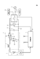
- the circuit diagram which shows the electrical storage apparatus of a solar power generation system. 6 is a flowchart showing an operation of the power storage device.
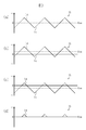
- (A)-(d) is a wave form diagram which shows the electric current which flows into the coil of a pressure
- the battery pack 1 includes a storage battery 5 and a BMU (battery management unit) that manages the charge / discharge state of the storage battery 5.
- the BMU 6 detects the cell voltage of the storage battery 5, SOC (State of charge: charge amount), the ambient temperature of the storage battery 5, and the like, and outputs each detection signal X to the charge / discharge control unit 4.
- the step-up / step-down circuit 2 includes a coil 7, a first switch 8 on the high side and a second switch 9 on the low side, each of which comprises a MOSFET (metal-oxide-semiconductor field-effect transistor). It is connected to high voltage DC bus line 10 via terminals t1 and t2.
- MOSFET metal-oxide-semiconductor field-effect transistor
- the first switch 8 and the second switch 9 are connected in series between the terminals t1 and t2, and the coil 7 is connected between the connection point of the first switch 8 and the second switch 9 and the positive terminal of the storage battery 5. Connected between. Further, the negative side terminal of the storage battery 5 is connected to the terminal t 2 via the step-up / step-down circuit 2.
- Control signals Q1 and Q2 from the charge / discharge control unit 4 are input to the gates of the first switch 8 and the second switch 9. Then, the first switch 8 and the second switch 9 are PWM-controlled by the control signals Q1 and Q2, and a step-up operation or a step-down operation is performed by cooperation with the coil 7.
- the output voltage of the storage battery 5 of 300 V is boosted to 380 V and supplied to the high voltage DC bus line 10.
- a direct-current voltage of 380 V supplied to the high-pressure direct-current bus line 10 is reduced to 300 V and supplied to the storage battery 5.
- a body diode D2 is interposed between the source and drain of the second switch 9, and a body diode D1 is interposed between the source and drain of the first switch 8.
- the body diode D2 is interposed such that the coil 7 side is a cathode, and the body diode D1 is interposed such that the coil 7 side is an anode.
- the smoothing capacitor 3 is connected between the terminals t 1 and t 2 to smooth the boosted voltage output from the step-up / step-down circuit 2 and output it to the high voltage DC bus line 10.
- a power conditioner 11 is connected to the high voltage DC bus line 10. To the power conditioner 11, the solar panel 12, the AC load 13 in the home, and the commercial power grid 14 are connected.
- the DC power generated by the solar panel 12 is boosted by the PV converter in the power conditioner 11 and converted into commercial AC power by the inverter and supplied to the AC load 13 or the commercial power system 14 in the home. Ru.
- the high voltage DC voltage boosted by the PV converter is supplied to the high voltage DC bus line 10.
- the voltage supplied to the high voltage DC bus line 10 is detected by the voltmeter 15, and the detected voltage V 1 is output to the charge / discharge control unit 4. Further, command signal CS for requesting the supply of the boosted voltage from power conditioner 11 to high voltage DC bus line 10 is input to charge / discharge control unit 4.
- the charge / discharge control unit 4 outputs control signals Q1 and Q2 based on a preset program to perform PWM control of the first and second switches 8 and 9.
- the step-up / step-down circuit 2 performs a step-up operation or a step-down operation based on the input of the control signals Q1 and Q2.
- the first switch 8 When the detection signal X is input from the BMU 6 to the charge / discharge control unit 4, the first switch 8 is turned off, and the supply of the charging current to the storage battery 5 is cut off.
- the charge / discharge control unit 4 receives the command signal CS from the power conditioner 11 when the detected voltage V1 inputted from the voltmeter 15 falls to a normal voltage of the high voltage DC bus line 10, for example, less than 380V. At this time, the step-up / step-down circuit 2 is boosted to supply a boosted voltage to the high-pressure DC bus line 10.
- the first and second switches 8 and 9 of the step-up / down circuit 2 are PWM-controlled by the charge / discharge control unit 4 by the control signals Q1 and Q2 and alternately turned on / off. Then, a boosting operation for boosting the output voltage of storage battery 5 and supplying the same to high voltage DC bus line 10 or a bucking operation for stepping down the high voltage supplied from high voltage DC bus line 10 from power conditioner 11 to storage battery 5 Is performed (step S1).
- step S2 based on the detection signal X output from the BMU 6, it is determined whether the ambient temperature of the storage battery 5 is within a predetermined temperature range set in advance (step S2), and if it is within the predetermined range, step S3. It is determined whether or not the cell voltage of the storage battery 5 has reached the preset upper limit value.
- step S4 the control signal Q1 for turning off the first switch 8 from the charge / discharge control unit 4 It is output. As a result, the supply of the charging current to the storage battery 5 is stopped.
- step S2 in order to avoid such a failure, it is determined based on the ambient temperature of the storage battery 5 whether the charging current to the storage battery 5 can be supplied.
- the charge / discharge control unit 4 continues to determine whether or not the SOC value of the storage battery 5 has become less than 100 based on the input detection signal X in a state in which the first switch 8 is maintained in the off state. (Steps S5 and S8).
- step S2 it is determined whether the ambient temperature of the storage battery 5 is within a predetermined temperature range set in advance (step S6).
- step S7 the off operation of the first switch 8 is released, and the process returns to step S1.
- step S6 If the ambient temperature of the storage battery 5 is out of the predetermined range in step S6, the first switch 8 is maintained in the OFF state, and the process returns to step S5. Therefore, the first switch 8 is maintained in the OFF state until the SOC value of the storage battery 5 is less than 100 and the ambient temperature of the storage battery 5 is within the predetermined range.
- step S8 When the detection voltage V1 of the voltmeter 15 decreases or the command signal CS is input from the power conditioner 11 while the first switch 8 is maintained in the OFF state in step S8, charge / discharge control is performed.
- the unit 4 resumes the PWM control of the first and second switches 8 and 9 and outputs the boosted voltage to the high voltage DC bus line 10.
- the current IL is a current flowing through the coil 7 when the first and second switches 8 and 9 of the step-up / down circuit 2 are PWM controlled, and the current on the + side is
- the discharge current Id flowing from the storage battery 5 toward the buck-boost circuit 2 is the charge current Ic flowing from the buck-boost circuit 2 toward the coil 7.
- the charging current Ic and the discharging current Id are in an equilibrium state, so the charging current Ic is not supplied to the storage battery 5, The discharge current Id does not flow from the storage battery 5.
- the charging current Ic becomes larger than the discharging current Id, so the charging current flows from the buck-boost circuit 2 to the storage battery 5 .
- the value of the current IL at the moment when the first switch 8 is turned off is sampled and held, and when the switching operation of the first switch 8 is resumed, the current obtained by sampling and holding the charging current Ic flowing through the coil 7
- the switching operation of the first and second switches 8 and 9 may be controlled so as not to exceed the value.
- the following effects can be obtained with the power storage device configured as described above.
- CS When CS is output, the first and second switches 8 and 9 can be returned to normal PWM control. Therefore, based on a drop in voltage of high voltage DC bus line 10 or an input of command signal CS from power conditioner 11, a discharge mode from storage battery 5, that is, boosted voltage is supplied to high voltage DC bus line 10 from buck-boost circuit 2. It is possible to immediately shift to the boost mode.
- step S3 shown in FIG. 2 it may be detected whether the SOC value has reached the upper limit value.
- the charge / discharge control unit 4 is configured to execute one or more memories storing computer readable instructions configured to realize various controls described in the embodiment and the computer readable instructions, for example. And one or more processors.
- the charge / discharge control unit 4 may be an integrated circuit such as an application specific IC (ASIC).
- ASIC application specific IC
Priority Applications (3)
| Application Number | Priority Date | Filing Date | Title |
|---|---|---|---|
| JP2019543480A JP6962379B2 (ja) | 2017-09-22 | 2018-08-17 | 蓄電装置 |
| CN201880061272.9A CN111149275B (zh) | 2017-09-22 | 2018-08-17 | 蓄电装置 |
| US16/823,546 US11522380B2 (en) | 2017-09-22 | 2020-03-19 | Power storage apparatus with voltage stepping-up/down bi-directional converter |
Applications Claiming Priority (2)
| Application Number | Priority Date | Filing Date | Title |
|---|---|---|---|
| JP2017-182595 | 2017-09-22 | ||
| JP2017182595 | 2017-09-22 |
Related Child Applications (1)
| Application Number | Title | Priority Date | Filing Date |
|---|---|---|---|
| US16/823,546 Continuation US11522380B2 (en) | 2017-09-22 | 2020-03-19 | Power storage apparatus with voltage stepping-up/down bi-directional converter |
Publications (1)
| Publication Number | Publication Date |
|---|---|
| WO2019058821A1 true WO2019058821A1 (ja) | 2019-03-28 |
Family
ID=65810388
Family Applications (1)
| Application Number | Title | Priority Date | Filing Date |
|---|---|---|---|
| PCT/JP2018/030468 WO2019058821A1 (ja) | 2017-09-22 | 2018-08-17 | 蓄電装置 |
Country Status (4)
| Country | Link |
|---|---|
| US (1) | US11522380B2 (zh) |
| JP (1) | JP6962379B2 (zh) |
| CN (1) | CN111149275B (zh) |
| WO (1) | WO2019058821A1 (zh) |
Families Citing this family (1)
| Publication number | Priority date | Publication date | Assignee | Title |
|---|---|---|---|---|
| CN113161637A (zh) * | 2021-03-03 | 2021-07-23 | 广西电网有限责任公司南宁供电局 | 一种铅酸电池硫酸盐化缓解方法及系统 |
Citations (4)
| Publication number | Priority date | Publication date | Assignee | Title |
|---|---|---|---|---|
| JP2005102469A (ja) * | 2003-09-05 | 2005-04-14 | Sanyo Electric Co Ltd | 電源ユニット及びこれを有する電源システム |
| JP2007252154A (ja) * | 2006-03-20 | 2007-09-27 | Fujitsu Ltd | Dc−dcコンバータ、dc−dcコンバータの制御回路、及びdc−dcコンバータの制御方法 |
| JP2010093888A (ja) * | 2008-10-06 | 2010-04-22 | Nippon Reliance Kk | 電源装置 |
| WO2017126175A1 (ja) * | 2016-01-18 | 2017-07-27 | 住友電気工業株式会社 | 電力変換システム及びその制御方法 |
Family Cites Families (90)
| Publication number | Priority date | Publication date | Assignee | Title |
|---|---|---|---|---|
| US4737702A (en) * | 1982-06-07 | 1988-04-12 | Norand Corporation | Battery charging control system particularly for hand held device |
| US5477132A (en) * | 1992-01-10 | 1995-12-19 | Space Systems/Loral, Inc. | Multi-sectioned power converter having current-sharing controller |
| JPH07115730A (ja) | 1993-10-15 | 1995-05-02 | Fuji Electric Co Ltd | 蓄電池の充放電回路の制御方法およびその制御器 |
| US5557188A (en) | 1994-02-01 | 1996-09-17 | Sun Microsystems, Inc. | Smart battery system and interface |
| US6184660B1 (en) * | 1998-03-26 | 2001-02-06 | Micro International, Ltd. | High-side current-sensing smart battery charger |
| US6118248A (en) * | 1998-04-02 | 2000-09-12 | The Procter & Gamble Company | Battery having a built-in controller to extend battery service run time |
| FR2777715B1 (fr) * | 1998-04-15 | 2000-06-09 | Agence Spatiale Europeenne | Module convertisseur d'alimentation electrique et systeme le comprenant |
| US6246220B1 (en) * | 1999-09-01 | 2001-06-12 | Intersil Corporation | Synchronous-rectified DC to DC converter with improved current sensing |
| US6700802B2 (en) * | 2000-02-14 | 2004-03-02 | Aura Systems, Inc. | Bi-directional power supply circuit |
| US6700214B2 (en) * | 2000-02-14 | 2004-03-02 | Aura Systems, Inc. | Mobile power generation system |
| US6166527A (en) * | 2000-03-27 | 2000-12-26 | Linear Technology Corporation | Control circuit and method for maintaining high efficiency in a buck-boost switching regulator |
| US6674274B2 (en) * | 2001-02-08 | 2004-01-06 | Linear Technology Corporation | Multiple phase switching regulators with stage shedding |
| US7034586B2 (en) * | 2004-03-05 | 2006-04-25 | Intersil Americas Inc. | Startup circuit for converter with pre-biased load |
| US7940016B2 (en) * | 2004-08-09 | 2011-05-10 | Railpower, Llc | Regenerative braking methods for a hybrid locomotive |
| JP4882235B2 (ja) * | 2005-01-27 | 2012-02-22 | ミツミ電機株式会社 | 電池保護用モジュール |
| JP3907123B1 (ja) * | 2006-02-17 | 2007-04-18 | 株式会社パワーシステム | キャパシタ蓄電電源用充電装置 |
| TWI320626B (en) * | 2006-09-12 | 2010-02-11 | Ablerex Electronics Co Ltd | Bidirectional active power conditioner |
| JP4179383B2 (ja) * | 2007-02-13 | 2008-11-12 | トヨタ自動車株式会社 | 駆動力発生システムおよびそれを備える車両、ならびにその制御方法 |
| US7932700B2 (en) * | 2007-03-26 | 2011-04-26 | The Gillette Company | Battery with integrated voltage converter |
| US7671574B1 (en) * | 2007-05-30 | 2010-03-02 | National Semiconductor Corporation | Ground voltage drop reduction circuit for a buck DC-DC converter |
| US7809517B1 (en) * | 2007-09-07 | 2010-10-05 | National Semiconductor Corporation | Apparatus and method for measuring phase noise/jitter in devices under test |
| US7889524B2 (en) * | 2007-10-19 | 2011-02-15 | Illinois Institute Of Technology | Integrated bi-directional converter for plug-in hybrid electric vehicles |
| JP5260957B2 (ja) * | 2007-12-28 | 2013-08-14 | 三菱電機株式会社 | 電力変換装置 |
| US8358107B2 (en) * | 2007-12-31 | 2013-01-22 | Intel Corporation | Bidirectional power management techniques |
| US7990119B2 (en) * | 2008-07-29 | 2011-08-02 | Telefonaktiebolaget L M Ericsson (Publ) | Multimode voltage regulator circuit |
| WO2010050046A1 (ja) * | 2008-10-31 | 2010-05-06 | トヨタ自動車株式会社 | 電動車両および電動車両の制御方法 |
| US8571733B2 (en) * | 2008-10-31 | 2013-10-29 | Toyota Jidosha Kabushiki Kaisha | Hybrid vehicle and method for controlling the same |
| WO2010050040A1 (ja) * | 2008-10-31 | 2010-05-06 | トヨタ自動車株式会社 | 電動車両の電源システムおよびその制御方法 |
| JP5287983B2 (ja) * | 2009-05-08 | 2013-09-11 | トヨタ自動車株式会社 | 電源システムおよびそれを備える車両 |
| WO2010138948A2 (en) * | 2009-05-28 | 2010-12-02 | Deeya Energy, Inc. | Buck-boost control circuit |
| JP4798305B2 (ja) * | 2009-06-10 | 2011-10-19 | トヨタ自動車株式会社 | 電動車両の電源システムおよびその制御方法 |
| EP2441617B1 (en) * | 2009-06-10 | 2018-08-29 | Toyota Jidosha Kabushiki Kaisha | Power supply system for electric vehicle, electric vehicle, and control method of power supply system for electric vehicle |
| JP5152408B2 (ja) * | 2009-06-10 | 2013-02-27 | トヨタ自動車株式会社 | ハイブリッド車両およびその制御方法 |
| JP5029784B2 (ja) * | 2009-06-10 | 2012-09-19 | トヨタ自動車株式会社 | 電動車両および電動車両の制御方法 |
| US8085005B2 (en) * | 2009-06-18 | 2011-12-27 | Micrel, Inc. | Buck-boost converter with sample and hold circuit in current loop |
| CN102511118B (zh) * | 2009-10-05 | 2014-08-06 | 日本碍子株式会社 | 控制装置、控制装置网以及控制方法 |
| JP5628820B2 (ja) * | 2009-10-05 | 2014-11-19 | 日本碍子株式会社 | 制御装置、制御装置網及び制御方法 |
| KR101084214B1 (ko) * | 2009-12-03 | 2011-11-18 | 삼성에스디아이 주식회사 | 계통 연계형 전력 저장 시스템 및 전력 저장 시스템 제어 방법 |
| KR101097260B1 (ko) * | 2009-12-15 | 2011-12-22 | 삼성에스디아이 주식회사 | 계통 연계형 전력 저장 시스템 및 전력 저장 시스템 제어 방법 |
| JP5189607B2 (ja) * | 2010-02-04 | 2013-04-24 | トヨタ自動車株式会社 | 車両用電源装置 |
| US20120074901A1 (en) * | 2010-09-27 | 2012-03-29 | Tim Mohammed | Centralized charging station |
| JPWO2012050207A1 (ja) * | 2010-10-15 | 2014-02-24 | 三洋電機株式会社 | 蓄電システム |
| JP5223932B2 (ja) * | 2011-01-19 | 2013-06-26 | 株式会社日本自動車部品総合研究所 | 直流電力供給装置 |
| US8669744B1 (en) * | 2011-02-15 | 2014-03-11 | Vlt, Inc. | Adaptive control of switching losses in power converters |
| CN108964442A (zh) * | 2011-05-05 | 2018-12-07 | 北极砂技术有限公司 | 用于电源转换的装置 |
| CN202218055U (zh) * | 2011-09-14 | 2012-05-09 | 华侨大学 | 一种离网型风光互补供电系统智能控制器 |
| US9473023B2 (en) * | 2012-08-10 | 2016-10-18 | Texas Instruments Incorporated | Switched mode assisted linear regulator with seamless transition between power tracking configurations |
| US9276475B2 (en) * | 2012-08-10 | 2016-03-01 | Texas Instruments Incorporated | Switched mode assisted linear regulator with decoupled output impedance and signal path bandwidth |
| US9112409B2 (en) * | 2012-08-10 | 2015-08-18 | Texas Instruments Incorporated | Switched mode assisted linear regulator with dynamic buck turn-off using ZCD-controlled tub switching |
| CN105052004A (zh) * | 2012-09-03 | 2015-11-11 | 罗伯特·博世(东南亚)私人有限公司 | 混合存储系统的拓扑和控制策略 |
| US9118193B2 (en) * | 2012-10-10 | 2015-08-25 | Ming-Hsiang Yeh | Bidirectional wireless charging/discharging device for portable electronic device |
| US20150073632A1 (en) * | 2013-03-12 | 2015-03-12 | Nicholas Hill | Tri-hybrid automotive power plant |
| JP6148882B2 (ja) * | 2013-03-13 | 2017-06-14 | 株式会社マキタ | バッテリパック及び充電器 |
| US10374447B2 (en) * | 2013-03-14 | 2019-08-06 | Infineon Technologies Austria Ag | Power converter circuit including at least one battery |
| US9548619B2 (en) * | 2013-03-14 | 2017-01-17 | Solaredge Technologies Ltd. | Method and apparatus for storing and depleting energy |
| US20190218894A9 (en) * | 2013-03-15 | 2019-07-18 | Fastcap Systems Corporation | Power system for downhole toolstring |
| US10333319B2 (en) * | 2013-05-17 | 2019-06-25 | Electro Standards Laboratories | Hybrid super-capacitor / rechargeable battery system |
| US9882380B2 (en) * | 2013-05-17 | 2018-01-30 | Electro Standards Laboratories | For hybrid super-capacitor / battery systems in pulsed power applications |
| US9634512B1 (en) * | 2013-12-03 | 2017-04-25 | Google Inc. | Battery backup with bi-directional converter |
| US9620975B2 (en) * | 2014-01-20 | 2017-04-11 | Nokia Technologies Oy | Methods and apparatus for battery characteristic conversion |
| WO2015132626A1 (en) * | 2014-03-03 | 2015-09-11 | Robert Bosch (Sea) Pte. Ltd. | Hybird storage system |
| WO2015132625A1 (en) * | 2014-03-03 | 2015-09-11 | Robert Bosch (Sea) Pte. Ltd. | Topology and control strategy for hybrid storage systems |
| CN106165241B (zh) * | 2014-03-06 | 2018-11-13 | 罗伯特·博世有限公司 | 改进的混合存储系统 |
| JP6247176B2 (ja) * | 2014-08-20 | 2017-12-13 | コーセル株式会社 | スイッチング電源装置 |
| US10056858B2 (en) * | 2014-09-17 | 2018-08-21 | Arm Limited | Motor driver and a method of operating thereof |
| JPWO2016103818A1 (ja) * | 2014-12-25 | 2017-08-31 | 株式会社村田製作所 | パワーコンディショナ |
| TWI614979B (zh) * | 2015-02-20 | 2018-02-11 | 線性科技股份有限公司 | 具有分離的高頻及低頻路徑信號的快速暫態電力供應器 |
| US9796277B2 (en) * | 2015-02-27 | 2017-10-24 | GM Global Technology Operations LLC | Electric bike extended range battery power electronics and control |
| US9812879B2 (en) * | 2015-07-21 | 2017-11-07 | John Russell Gravett | Battery thermal monitoring system |
| US10270275B2 (en) * | 2015-08-27 | 2019-04-23 | General Electric Company | Systems and methods for controlling energy storage systems having multiple battery types |
| CA2997565A1 (en) * | 2015-09-11 | 2017-03-16 | Invertedpower Pty Ltd | A controller for an inductive load having one or more inductive windings |
| US20170072812A1 (en) * | 2015-09-16 | 2017-03-16 | Qualcomm Incorporated | Battery Management Systems for Autonomous Vehicles |
| KR20170050014A (ko) * | 2015-10-29 | 2017-05-11 | 엘에스오토모티브 주식회사 | 역률 보상 장치 및 이의 동작 방법 |
| US20170170732A1 (en) * | 2015-12-15 | 2017-06-15 | Neofocal Systems, Inc. | System and method for zero voltage switching and switch capacator modulation |
| JP6399239B2 (ja) * | 2016-01-08 | 2018-10-03 | 株式会社村田製作所 | 電力変換装置 |
| US10050559B2 (en) * | 2016-01-20 | 2018-08-14 | Linear Technology Llc | Control architecture with improved transient response |
| US10326296B2 (en) * | 2016-02-01 | 2019-06-18 | Qualcomm Incorporated | Dual-phase operation for concurrently charging a battery and powering a peripheral device |
| US9882476B2 (en) * | 2016-05-31 | 2018-01-30 | Infineon Tehnologies Austria AG | Method and apparatus for phase current estimation in semi-resonant voltage converters |
| KR20180017339A (ko) * | 2016-08-09 | 2018-02-21 | 삼성전자주식회사 | 전원 관리 집적 회로를 포함하는 전자 장치 |
| JP6677186B2 (ja) * | 2017-01-26 | 2020-04-08 | 株式会社村田製作所 | 直流給電システム |
| US10439404B2 (en) * | 2017-04-13 | 2019-10-08 | Microsoft Technology Licensing, Llc | Hybrid battery pack including bi-directional charge regulator |
| WO2019054138A1 (ja) * | 2017-09-15 | 2019-03-21 | 株式会社村田製作所 | 蓄電装置用昇降圧装置及び蓄電装置 |
| CN109683104A (zh) * | 2017-10-12 | 2019-04-26 | 本田技研工业株式会社 | 电池状态推定方法以及电池状态推定装置 |
| CN111226364B (zh) * | 2017-10-17 | 2022-06-28 | 株式会社村田制作所 | 电源装置、电力控制装置、电源装置的继电器判定方法 |
| WO2019097926A1 (ja) * | 2017-11-16 | 2019-05-23 | 株式会社村田製作所 | 蓄電モジュールおよび電源システム |
| CN107947578B (zh) * | 2017-12-04 | 2020-09-15 | 成都芯源系统有限公司 | 一种应用于升降压电路的电流采样电路及其控制方法 |
| US10014778B1 (en) * | 2018-01-12 | 2018-07-03 | BravoTek Electronics Co., Ltd. | SIBO buck-boost converter and control method thereof |
| EP3530516B1 (en) * | 2018-02-23 | 2022-07-06 | Ningbo Geely Automobile Research & Development Co. Ltd. | Electrical battery system |
| JP6649418B2 (ja) * | 2018-02-26 | 2020-02-19 | ファナック株式会社 | 蓄電装置を有するモータ駆動システム |
| US20200070806A1 (en) * | 2018-08-31 | 2020-03-05 | N4 Innovations, Llc | Vehicle Power Control System |
-
2018
- 2018-08-17 WO PCT/JP2018/030468 patent/WO2019058821A1/ja active Application Filing
- 2018-08-17 JP JP2019543480A patent/JP6962379B2/ja active Active
- 2018-08-17 CN CN201880061272.9A patent/CN111149275B/zh active Active
-
2020
- 2020-03-19 US US16/823,546 patent/US11522380B2/en active Active
Patent Citations (4)
| Publication number | Priority date | Publication date | Assignee | Title |
|---|---|---|---|---|
| JP2005102469A (ja) * | 2003-09-05 | 2005-04-14 | Sanyo Electric Co Ltd | 電源ユニット及びこれを有する電源システム |
| JP2007252154A (ja) * | 2006-03-20 | 2007-09-27 | Fujitsu Ltd | Dc−dcコンバータ、dc−dcコンバータの制御回路、及びdc−dcコンバータの制御方法 |
| JP2010093888A (ja) * | 2008-10-06 | 2010-04-22 | Nippon Reliance Kk | 電源装置 |
| WO2017126175A1 (ja) * | 2016-01-18 | 2017-07-27 | 住友電気工業株式会社 | 電力変換システム及びその制御方法 |
Also Published As
| Publication number | Publication date |
|---|---|
| JP6962379B2 (ja) | 2021-11-05 |
| US20200220370A1 (en) | 2020-07-09 |
| CN111149275B (zh) | 2023-09-12 |
| CN111149275A (zh) | 2020-05-12 |
| US11522380B2 (en) | 2022-12-06 |
| JPWO2019058821A1 (ja) | 2020-10-15 |
Similar Documents
| Publication | Publication Date | Title |
|---|---|---|
| KR101308783B1 (ko) | 무정전 전원 장치 | |
| JP6741169B2 (ja) | 電源装置、電力制御装置、電源装置のリレー判定方法 | |
| WO2012115098A1 (ja) | 蓄電システム | |
| JP2017126477A (ja) | 燃料電池システム及びその制御方法 | |
| EP3525317B1 (en) | Electrical device | |
| JP2018170930A (ja) | 電力変換装置、電力変換システム | |
| CN105337335B (zh) | 针对多个电池匹配放电结束的系统和方法 | |
| JP2017085892A (ja) | 蓄電池用変換装置、電力供給システムおよび電力供給制御方法 | |
| US10826318B2 (en) | Voltage increasing and decreasing device for power storage apparatus and power storage apparatus | |
| JPWO2012043744A1 (ja) | 充電制御装置 | |
| CN108832710B (zh) | 用于不间断电源的充放电平衡变换器 | |
| US10263446B2 (en) | Battery control circuit for power generation system using renewable energy | |
| US11522380B2 (en) | Power storage apparatus with voltage stepping-up/down bi-directional converter | |
| JP2015046992A (ja) | 車両用電源供給装置 | |
| JP2013070547A (ja) | 電力変換装置 | |
| JP2015213384A (ja) | 電池電圧補償システム | |
| JP2008035573A (ja) | 電気二重層コンデンサを用いた蓄電装置 | |
| JP2017205013A (ja) | 蓄電池用変換装置、電力供給システムおよび電力供給制御方法 | |
| JP2015198474A (ja) | 電池システム | |
| US20230147151A1 (en) | Charging Apparatus and Method Using Auxiliary Battery | |
| US20230253815A1 (en) | Battery charge/discharge testing device and battery discharge power control method | |
| CN215835191U (zh) | 一种直流不间断电源 | |
| WO2022234784A1 (ja) | 電力変換装置 | |
| CN116349125A (zh) | 电压转换电路的控制方法、装置及电子设备 | |
| JP2023082913A (ja) | 充放電装置、蓄電システム、及び、充放電制御方法 |
Legal Events
| Date | Code | Title | Description |
|---|---|---|---|
| 121 | Ep: the epo has been informed by wipo that ep was designated in this application |
Ref document number: 18859652 Country of ref document: EP Kind code of ref document: A1 |
|
| ENP | Entry into the national phase |
Ref document number: 2019543480 Country of ref document: JP Kind code of ref document: A |
|
| NENP | Non-entry into the national phase |
Ref country code: DE |
|
| 122 | Ep: pct application non-entry in european phase |
Ref document number: 18859652 Country of ref document: EP Kind code of ref document: A1 |