WO2018203168A1 - 正極活物質粒子の作製方法、および二次電池 - Google Patents
正極活物質粒子の作製方法、および二次電池 Download PDFInfo
- Publication number
- WO2018203168A1 WO2018203168A1 PCT/IB2018/052700 IB2018052700W WO2018203168A1 WO 2018203168 A1 WO2018203168 A1 WO 2018203168A1 IB 2018052700 W IB2018052700 W IB 2018052700W WO 2018203168 A1 WO2018203168 A1 WO 2018203168A1
- Authority
- WO
- WIPO (PCT)
- Prior art keywords
- positive electrode
- secondary battery
- active material
- electrode active
- lithium
- Prior art date
- Legal status (The legal status is an assumption and is not a legal conclusion. Google has not performed a legal analysis and makes no representation as to the accuracy of the status listed.)
- Ceased
Links
Images




Classifications
-
- H—ELECTRICITY
- H01—ELECTRIC ELEMENTS
- H01M—PROCESSES OR MEANS, e.g. BATTERIES, FOR THE DIRECT CONVERSION OF CHEMICAL ENERGY INTO ELECTRICAL ENERGY
- H01M4/00—Electrodes
- H01M4/02—Electrodes composed of, or comprising, active material
- H01M4/04—Processes of manufacture in general
- H01M4/0471—Processes of manufacture in general involving thermal treatment, e.g. firing, sintering, backing particulate active material, thermal decomposition, pyrolysis
-
- H—ELECTRICITY
- H01—ELECTRIC ELEMENTS
- H01M—PROCESSES OR MEANS, e.g. BATTERIES, FOR THE DIRECT CONVERSION OF CHEMICAL ENERGY INTO ELECTRICAL ENERGY
- H01M4/00—Electrodes
- H01M4/02—Electrodes composed of, or comprising, active material
- H01M4/36—Selection of substances as active materials, active masses, active liquids
- H01M4/362—Composites
- H01M4/366—Composites as layered products
-
- H—ELECTRICITY
- H01—ELECTRIC ELEMENTS
- H01M—PROCESSES OR MEANS, e.g. BATTERIES, FOR THE DIRECT CONVERSION OF CHEMICAL ENERGY INTO ELECTRICAL ENERGY
- H01M10/00—Secondary cells; Manufacture thereof
- H01M10/05—Accumulators with non-aqueous electrolyte
- H01M10/052—Li-accumulators
-
- H—ELECTRICITY
- H01—ELECTRIC ELEMENTS
- H01M—PROCESSES OR MEANS, e.g. BATTERIES, FOR THE DIRECT CONVERSION OF CHEMICAL ENERGY INTO ELECTRICAL ENERGY
- H01M10/00—Secondary cells; Manufacture thereof
- H01M10/05—Accumulators with non-aqueous electrolyte
- H01M10/052—Li-accumulators
- H01M10/0525—Rocking-chair batteries, i.e. batteries with lithium insertion or intercalation in both electrodes; Lithium-ion batteries
-
- H—ELECTRICITY
- H01—ELECTRIC ELEMENTS
- H01M—PROCESSES OR MEANS, e.g. BATTERIES, FOR THE DIRECT CONVERSION OF CHEMICAL ENERGY INTO ELECTRICAL ENERGY
- H01M4/00—Electrodes
- H01M4/02—Electrodes composed of, or comprising, active material
- H01M4/04—Processes of manufacture in general
- H01M4/0402—Methods of deposition of the material
- H01M4/0419—Methods of deposition of the material involving spraying
-
- H—ELECTRICITY
- H01—ELECTRIC ELEMENTS
- H01M—PROCESSES OR MEANS, e.g. BATTERIES, FOR THE DIRECT CONVERSION OF CHEMICAL ENERGY INTO ELECTRICAL ENERGY
- H01M4/00—Electrodes
- H01M4/02—Electrodes composed of, or comprising, active material
- H01M4/13—Electrodes for accumulators with non-aqueous electrolyte, e.g. for lithium-accumulators; Processes of manufacture thereof
- H01M4/139—Processes of manufacture
- H01M4/1391—Processes of manufacture of electrodes based on mixed oxides or hydroxides, or on mixtures of oxides or hydroxides, e.g. LiCoOx
-
- H—ELECTRICITY
- H01—ELECTRIC ELEMENTS
- H01M—PROCESSES OR MEANS, e.g. BATTERIES, FOR THE DIRECT CONVERSION OF CHEMICAL ENERGY INTO ELECTRICAL ENERGY
- H01M4/00—Electrodes
- H01M4/02—Electrodes composed of, or comprising, active material
- H01M4/36—Selection of substances as active materials, active masses, active liquids
- H01M4/48—Selection of substances as active materials, active masses, active liquids of inorganic oxides or hydroxides
- H01M4/485—Selection of substances as active materials, active masses, active liquids of inorganic oxides or hydroxides of mixed oxides or hydroxides for inserting or intercalating light metals, e.g. LiTi2O4 or LiTi2OxFy
-
- H—ELECTRICITY
- H01—ELECTRIC ELEMENTS
- H01M—PROCESSES OR MEANS, e.g. BATTERIES, FOR THE DIRECT CONVERSION OF CHEMICAL ENERGY INTO ELECTRICAL ENERGY
- H01M4/00—Electrodes
- H01M4/02—Electrodes composed of, or comprising, active material
- H01M4/36—Selection of substances as active materials, active masses, active liquids
- H01M4/48—Selection of substances as active materials, active masses, active liquids of inorganic oxides or hydroxides
- H01M4/50—Selection of substances as active materials, active masses, active liquids of inorganic oxides or hydroxides of manganese
- H01M4/505—Selection of substances as active materials, active masses, active liquids of inorganic oxides or hydroxides of manganese of mixed oxides or hydroxides containing manganese for inserting or intercalating light metals, e.g. LiMn2O4 or LiMn2OxFy
-
- H—ELECTRICITY
- H01—ELECTRIC ELEMENTS
- H01M—PROCESSES OR MEANS, e.g. BATTERIES, FOR THE DIRECT CONVERSION OF CHEMICAL ENERGY INTO ELECTRICAL ENERGY
- H01M4/00—Electrodes
- H01M4/02—Electrodes composed of, or comprising, active material
- H01M4/36—Selection of substances as active materials, active masses, active liquids
- H01M4/48—Selection of substances as active materials, active masses, active liquids of inorganic oxides or hydroxides
- H01M4/52—Selection of substances as active materials, active masses, active liquids of inorganic oxides or hydroxides of nickel, cobalt or iron
- H01M4/525—Selection of substances as active materials, active masses, active liquids of inorganic oxides or hydroxides of nickel, cobalt or iron of mixed oxides or hydroxides containing iron, cobalt or nickel for inserting or intercalating light metals, e.g. LiNiO2, LiCoO2 or LiCoOxFy
-
- H—ELECTRICITY
- H01—ELECTRIC ELEMENTS
- H01M—PROCESSES OR MEANS, e.g. BATTERIES, FOR THE DIRECT CONVERSION OF CHEMICAL ENERGY INTO ELECTRICAL ENERGY
- H01M4/00—Electrodes
- H01M4/02—Electrodes composed of, or comprising, active material
- H01M4/36—Selection of substances as active materials, active masses, active liquids
- H01M4/58—Selection of substances as active materials, active masses, active liquids of inorganic compounds other than oxides or hydroxides, e.g. sulfides, selenides, tellurides, halogenides or LiCoFy; of polyanionic structures, e.g. phosphates, silicates or borates
- H01M4/583—Carbonaceous material, e.g. graphite-intercalation compounds or CFx
- H01M4/5835—Comprising fluorine or fluoride salts
-
- H—ELECTRICITY
- H01—ELECTRIC ELEMENTS
- H01M—PROCESSES OR MEANS, e.g. BATTERIES, FOR THE DIRECT CONVERSION OF CHEMICAL ENERGY INTO ELECTRICAL ENERGY
- H01M4/00—Electrodes
- H01M4/02—Electrodes composed of, or comprising, active material
- H01M4/62—Selection of inactive substances as ingredients for active masses, e.g. binders, fillers
-
- H—ELECTRICITY
- H01—ELECTRIC ELEMENTS
- H01M—PROCESSES OR MEANS, e.g. BATTERIES, FOR THE DIRECT CONVERSION OF CHEMICAL ENERGY INTO ELECTRICAL ENERGY
- H01M4/00—Electrodes
- H01M4/02—Electrodes composed of, or comprising, active material
- H01M4/62—Selection of inactive substances as ingredients for active masses, e.g. binders, fillers
- H01M4/624—Electric conductive fillers
- H01M4/625—Carbon or graphite
-
- H—ELECTRICITY
- H01—ELECTRIC ELEMENTS
- H01M—PROCESSES OR MEANS, e.g. BATTERIES, FOR THE DIRECT CONVERSION OF CHEMICAL ENERGY INTO ELECTRICAL ENERGY
- H01M4/00—Electrodes
- H01M4/02—Electrodes composed of, or comprising, active material
- H01M2004/026—Electrodes composed of, or comprising, active material characterised by the polarity
- H01M2004/027—Negative electrodes
-
- H—ELECTRICITY
- H01—ELECTRIC ELEMENTS
- H01M—PROCESSES OR MEANS, e.g. BATTERIES, FOR THE DIRECT CONVERSION OF CHEMICAL ENERGY INTO ELECTRICAL ENERGY
- H01M4/00—Electrodes
- H01M4/02—Electrodes composed of, or comprising, active material
- H01M2004/026—Electrodes composed of, or comprising, active material characterised by the polarity
- H01M2004/028—Positive electrodes
-
- H—ELECTRICITY
- H01—ELECTRIC ELEMENTS
- H01M—PROCESSES OR MEANS, e.g. BATTERIES, FOR THE DIRECT CONVERSION OF CHEMICAL ENERGY INTO ELECTRICAL ENERGY
- H01M2220/00—Batteries for particular applications
- H01M2220/20—Batteries in motive systems, e.g. vehicle, ship, plane
-
- H—ELECTRICITY
- H01—ELECTRIC ELEMENTS
- H01M—PROCESSES OR MEANS, e.g. BATTERIES, FOR THE DIRECT CONVERSION OF CHEMICAL ENERGY INTO ELECTRICAL ENERGY
- H01M2300/00—Electrolytes
- H01M2300/0017—Non-aqueous electrolytes
- H01M2300/0065—Solid electrolytes
- H01M2300/0068—Solid electrolytes inorganic
-
- H—ELECTRICITY
- H01—ELECTRIC ELEMENTS
- H01M—PROCESSES OR MEANS, e.g. BATTERIES, FOR THE DIRECT CONVERSION OF CHEMICAL ENERGY INTO ELECTRICAL ENERGY
- H01M2300/00—Electrolytes
- H01M2300/0017—Non-aqueous electrolytes
- H01M2300/0065—Solid electrolytes
- H01M2300/0068—Solid electrolytes inorganic
- H01M2300/0071—Oxides
-
- Y—GENERAL TAGGING OF NEW TECHNOLOGICAL DEVELOPMENTS; GENERAL TAGGING OF CROSS-SECTIONAL TECHNOLOGIES SPANNING OVER SEVERAL SECTIONS OF THE IPC; TECHNICAL SUBJECTS COVERED BY FORMER USPC CROSS-REFERENCE ART COLLECTIONS [XRACs] AND DIGESTS
- Y02—TECHNOLOGIES OR APPLICATIONS FOR MITIGATION OR ADAPTATION AGAINST CLIMATE CHANGE
- Y02E—REDUCTION OF GREENHOUSE GAS [GHG] EMISSIONS, RELATED TO ENERGY GENERATION, TRANSMISSION OR DISTRIBUTION
- Y02E60/00—Enabling technologies; Technologies with a potential or indirect contribution to GHG emissions mitigation
- Y02E60/10—Energy storage using batteries
Definitions
- One embodiment of the present invention relates to an object, a method, or a manufacturing method. Alternatively, one embodiment of the present invention relates to a process, a machine, a manufacture, or a composition (composition of matter). One embodiment of the present invention relates to a semiconductor device, a display device, a light-emitting device, a power storage device, a lighting device, an electronic device, or a manufacturing method thereof. In particular, the present invention relates to a positive electrode active material that can be used for a secondary battery, a secondary battery, and an electronic device having the secondary battery.
- a power storage device refers to all elements and devices having a power storage function.
- a storage battery also referred to as a secondary battery
- a lithium ion secondary battery such as a lithium ion secondary battery, a lithium ion capacitor, and an electric double layer capacitor are included.
- High-power, high-capacity lithium-ion secondary batteries can be used for portable information terminals such as mobile phones, smartphones or notebook computers, portable music players, digital cameras, medical devices, hybrid vehicles (HEV), electric vehicles (EV), or next-generation clean energy vehicles such as plug-in hybrid vehicles (PHEV), and the demand for them rapidly expands with the development of the semiconductor industry, and is essential for the modern information society as a source of rechargeable energy It has become a thing.
- portable information terminals such as mobile phones, smartphones or notebook computers, portable music players, digital cameras, medical devices, hybrid vehicles (HEV), electric vehicles ( EV), or next-generation clean energy vehicles such as plug-in hybrid vehicles (PHEV), and the demand for them rapidly expands with the development of the semiconductor industry, and is essential for the modern information society as a source of rechargeable energy It has become a thing.
- HEV hybrid vehicles
- EV electric vehicles
- PHEV plug-in hybrid vehicles
- lithium ion secondary batteries are required to have high capacity, high energy density, small size, and light weight.
- Patent Document 1 discloses plate-like particles of a positive electrode active material.
- the charging voltage applied to the secondary battery can be increased, the time for charging at a high voltage is extended, the amount of charge per unit time is increased, and the charging time is shortened.
- battery deterioration occurs when the voltage exceeds a high voltage of 4.5V.
- the side reaction refers to the formation of a reaction product generated by causing a chemical reaction of the active material or the electrolytic solution.
- Other side reactions refer to the promotion of oxidation and decomposition of the electrolyte. Further, gas decomposition and volume expansion may occur due to decomposition of the electrolytic solution.
- An object of one embodiment of the present invention is to suppress side reactions with an electrolytic solution and to improve high voltage resistance and rate characteristics.
- Another object of one embodiment of the present invention is to provide a novel material, active material particles, a secondary battery, or a manufacturing method thereof.
- the positive electrode active material particles it is preferable to modify the positive electrode active material particles so that side reactions do not occur even when charge / discharge is performed in a state where the modified positive electrode active material particles are in contact with the electrolytic solution. . Further, since the positive electrode active material particles are small and many, it is desired to modify each one.
- the secondary battery is deteriorated by a chemical reaction such as a side reaction.
- a chemical reaction such as a side reaction.
- an unintended chemical reaction is not performed, and the state of the positive electrode, the state of the electrolytic solution, or the state of the negative electrode is maintained.
- the protective layer In order to prevent side reactions in charge and discharge, it is desirable to provide a protective layer between the electrolytic solution and the positive electrode active particles, and the protective layer should pass carrier ions such as lithium ions.
- the protective layer In order not to inhibit the movement of carrier ions such as lithium ions, the protective layer is thinned, or the protective layer is provided only on a part of the surface of the positive electrode active material particles. In addition, the protective layer may not be provided as long as it can be modified into particles that do not easily react with the electrolytic solution.
- the positive electrode active material particles that are not modified remain by simply mixing, or each positive electrode active material particle
- the positive active material particles having a protective layer are mixed with positive active material particles having no protective layer.
- carrier ions such as lithium ions are preferentially taken in and out due to the presence of unmodified positive electrode active material particles and the presence of positive electrode active material particles without a protective layer. The deterioration of these particles is accelerated compared to other particles, and the life of the secondary battery is shortened.
- the present inventors use a graphene compound, lithium compound particles having lithium, a transition metal element, and oxygen, a graphene compound, and a solid
- a suspension containing an electrolyte and a solvent from a nozzle of a spray drying device
- the positive electrode active material particles contained in droplets discharged from the nozzle can be dried in a state where the graphene compound is clinging together.
- a suspension is a liquid in which solid particles are dispersed in a liquid, and the particles sprayed from the nozzle include solid single particles, solid agglomerated particles, liquid-only particles, There are mixed particles of liquid and solid particles. Note that solid particles may settle in the suspension and have a concentration gradient.
- the structure related to the manufacturing method disclosed in this specification includes spraying a suspension including lithium compound particles including lithium, a transition metal element, and oxygen, a graphene compound, a solid electrolyte, and a solvent, and is included in the surface by heating.
- This is a method for producing positive electrode active material particles by changing carbon to carbon dioxide gas and volatilizing it.
- spraying may be performed using a spray nozzle, and the nozzle diameter may be larger than the size of the lithium compound particles.
- a nozzle having a larger nozzle diameter than the particles contained in the suspension is used.
- a NASICON type phosphoric acid compound is used as the solid electrolyte.
- the solvent is water and ethanol.
- the heating is performed at a temperature equal to or higher than the melting point of the solid electrolyte in an air atmosphere.
- the solid electrolyte has ion conductivity and is solid at room temperature, for example, 15 ° C. or more and 25 ° C. or less.
- the solid electrolyte may be crystalline or amorphous.
- a gel polymer solid electrolyte containing a solution may be included.
- the transition metal is cobalt.
- a solid phase method is used for producing lithium compound particles.
- the solid phase method is not particularly limited, and a sol-gel method may be used.
- a secondary battery using positive electrode active material particles obtained by the above production method is one of the inventions disclosed in this specification, and the configuration thereof includes lithium compound particles having lithium, a transition metal element, and oxygen
- the secondary battery includes a positive electrode having a phosphoric acid compound in contact with the lithium compound particles, an electrolytic solution in contact with the lithium compound particles and the phosphoric acid compound, and a negative electrode.
- the protective layer is a secondary battery containing carbon.
- a solid electrolyte material through which carrier ions such as lithium ions can pass is used. That is, a plurality of materials limited to one droplet, specifically, solid electrolyte particles, positive electrode active material particles, and a graphene compound are included and sprayed from a spray nozzle to efficiently produce positive electrode active material particles. And solid electrolyte particles can be attached.
- the lithium compound particles have magnesium and fluorine, and have a gradient in which magnesium or fluorine is contained at a higher concentration on the surface of the lithium compound particles than in the lithium compound particles. Further, after the heating, the titanium contained in the solid electrolyte particles is diffused so that the positive electrode active material particles contain titanium. Further, the graphene compound may remain after heating, and a protective layer containing carbon may be provided on the surface of the positive electrode active material particles. This carbon can be detected by XRD analysis or Raman spectroscopic analysis.
- a phosphoric acid compound is preferable. Phosphoric acid compounds are easier to handle than sulfurized compounds and do not generate harmful gases such as sulfurized gas in the manufacturing process. Further, the phosphoric acid compound is a compound that is stable even in the air atmosphere, and has an advantage that it does not require large-scale atmosphere control.
- a phosphate compound containing lithium, aluminum, and titanium (hereinafter referred to as LATP) is also called a ceramic electrolyte, and is a material having high water resistance, and is a glass ceramic electrolyte.
- LATP is, Li 1 + X Al X Ti 2-X (PO 4) 3.
- LATP is one of solid electrolyte materials having a NASICON type crystal structure.
- the protective layer is not limited to one type of material, and a plurality of types of protective layers may be in contact with the surface.
- the positive electrode active material particles obtained according to the present invention have a surface that does not easily react with the electrolyte even after repeated charge and discharge, and can suppress a decrease in capacity during the charge and discharge cycle. Moreover, the secondary battery using the positive electrode active material particles obtained by the present invention can realize a high capacity. Moreover, the secondary battery using the positive electrode active material particles obtained by the present invention exhibits excellent charge / discharge characteristics. Moreover, the secondary battery using the positive electrode active material particles obtained by the present invention has high safety or high reliability.
- FIG. 6 is a diagram illustrating a manufacturing flow illustrating one embodiment of the present invention. It is a SEM photograph before the heating of the positive electrode active material particle which shows 1 aspect of this invention. It is the SEM photograph after heating of the positive electrode active material particle which shows one aspect
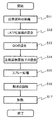
- FIG. 1 shows a process flow diagram.
- starting materials are prepared (S11).
- lithium cobalt oxide (LCO) as a positive electrode active material
- graphene oxide also referred to as GO
- LATP Li 1.3 Al 0.3 Ti 1.7 (PO 4 ) 3 as a solid electrolyte.
- LATP particles were obtained by performing ball mill crushing and drying in order to control to an appropriate particle size.
- the composition of the LATP particles can be confirmed from the result of X-ray diffraction analysis (XRD). According to the particle size distribution measurement, the particle size of the LATP particles is about 100 nm to 5 ⁇ m, and the average is 700 nm.
- Water and ethanol are put into a container containing LATP particles, and mixing and stirring are performed (S12).
- the ratio of ethanol and pure water is 4: 6.
- a stirrer is used for stirring, the rotation speed is 750 rpm, and ultrasonic waves are applied for 1 minute.
- pure water and ethanol are used as a dispersion medium in (S12), it is not specifically limited, You may use organic solvents, such as only ethanol or acetone, 2-propanol.
- graphene oxide is put into the container, and mixing and stirring are performed (S13).
- a stirrer is used for stirring, the rotation speed is 750 rpm, and ultrasonic waves are applied for 1 minute.
- LATP can be mixed without precipitation.
- the positive electrode active material particles are put into a container and mixed and stirred (S14).
- a stirrer is used for stirring, the rotation speed is 750 rpm, and ultrasonic waves are applied for 1 minute.
- a suspension is completed using lithium cobaltate particles (trade name: C-20F) manufactured by Nippon Chemical Industry Co., Ltd. as positive electrode active material particles.
- the lithium cobalt oxide particles (trade name: C-20F) manufactured by Nippon Chemical Industry Co., Ltd. are lithium cobalt oxide particles containing at least fluorine, magnesium, calcium, sodium, silicon, sulfur, and phosphorus, and have a particle size of about 20 ⁇ m. It is.
- the suspension is sprayed using a spray dryer (S15).
- FIG. 1 A schematic diagram of the spray drying apparatus 280 is shown in FIG.
- the spray drying apparatus 280 has a chamber 281 and a nozzle 282.
- the suspension 284 is supplied to the nozzle 282 through the tube 283.
- the suspension 284 is supplied as a spray from the nozzle 282 into the chamber 281 and dried in the chamber 281.
- the nozzle 282 may be heated by the heater 285.
- the heater 285 also heats a region near the nozzle 282 in the chamber 281, for example, a region surrounded by a two-dot chain line shown in FIG. 4.
- the positive electrode active material powder to which LATP and graphene oxide are attached is collected into the collection containers 286, 287 through the chamber 281. Is done.
- the atmosphere in the chamber 281 may be sucked by an aspirator or the like through a path indicated by an arrow 288.
- the suspension was sprayed uniformly with a spray nozzle (nozzle diameter 20 ⁇ m) to obtain a powder.
- the inlet temperature was 160 ° C.
- the outlet temperature was 40 ° C.
- the nitrogen gas flow rate was 10 L / min.
- nitrogen gas is used here, argon gas may be used.
- FIG. 2 An SEM photograph of the powder obtained in the collection container 287 is shown in FIG. In FIG. 2, a portion where small LATP particles are attached to one particle of the positive electrode active material and graphene oxide is further attached thereto can be observed. Since it is composed of a plurality of materials, the particle shown in FIG. 2 can also be called a composite structure.
- the powder obtained in the collection container 287 is heated at a heating temperature equal to or higher than the synthesis temperature of LATP, here 900 ° C., for 2 hours in an air atmosphere (S17).
- the temperature rise temperature is 200 ° C./hour.
- An SEM photograph of the powder after the heat treatment is shown in FIG. In the photograph of the powder after the heat treatment, it is not possible to confirm that the graphene oxide seen before the heating is attached, and it seems that most of the carbon dioxide gas was produced.
- FIG. 3A A cross-sectional view taken along a straight line in FIG. 3A is shown in FIG.
- Heat treatment causes a solid diffusion reaction, and magnesium and fluorine are diffused from the inside of the positive electrode active material particles to the vicinity of the surface, defect areas such as grain boundaries and cracks, and the concentration of magnesium and fluorine near the surface increases. It is thought. In addition, it is considered that small LATP particles adhered to lithium cobaltate particles, titanium diffused from LATP, and was detected near the surface. Thus, it can be said that the positive electrode active material particles are surface-modified and a new layer is formed on the surface of the positive electrode active material particles.
- a positive electrode of a secondary battery When a positive electrode of a secondary battery is constructed using positive electrode active material particles in which this new layer functions as a protective layer, it has a surface that does not easily react with the electrolyte even if it is repeatedly charged and discharged, and the capacity in the charge / discharge cycle Can be suppressed.
- a layered rock salt type lithium cobalt oxide is used as the positive electrode active material particles, but the present invention is not particularly limited, and a material having a high charging voltage (4.5 V or more), specifically a layered rock salt type.
- Nickel-manganese-lithium cobaltate, lithium nickelate, nickel-cobalt-lithium aluminum oxide, spinel-type nickel-lithium manganate (LiNi 0.5 Mn 1.5 O 4 ), and the like can be used.
- the amount of LATP particles is preferable to control the amount of LATP particles to a very small amount, more than 0.2 wt% and less than 8 wt%, preferably 1 wt% or more and 3 wt% or less.
- the graphene oxide is preferably 0.2 wt% or more, and is preferably 0.6 wt% or less considering the cost of the graphene oxide.
- a next-generation clean energy vehicle such as a hybrid vehicle (HEV), an electric vehicle (EV), or a plug-in hybrid vehicle (PHEV) can be realized.
- HEV hybrid vehicle
- EV electric vehicle
- PHEV plug-in hybrid vehicle
- FIG. 11 illustrates a vehicle using the secondary battery which is one embodiment of the present invention.
- a car 8400 illustrated in FIG. 11A is an electric car that uses an electric motor as a power source for traveling. Or it is a hybrid vehicle which can select and use an electric motor and an engine suitably as a motive power source for driving
- the automobile 8400 includes a secondary battery.
- the secondary battery may be used by arranging a module of a laminate type secondary battery on the floor portion in the vehicle. Moreover, you may install the battery pack which combined multiple secondary batteries with respect to the floor part in a vehicle.
- the secondary battery not only drives the electric motor 8406 but can supply power to a light-emitting device such as a headlight 8401 or a room light (not shown).
- the secondary battery can supply power to a display device such as a speedometer or a tachometer included in the automobile 8400.
- the secondary battery can supply power to a semiconductor device such as a navigation system included in the automobile 8400.
- FIG. 11B An automobile 8500 illustrated in FIG. 11B can charge a secondary battery of the automobile 8500 by receiving power from an external charging facility by a plug-in method, a non-contact power feeding method, or the like.
- FIG. 11B illustrates a state where the secondary battery 8024 mounted on the automobile 8500 is charged through the cable 8022 from the ground-installed charging device 8021.
- the charging method, connector standard, and the like may be appropriately performed by a predetermined method such as CHAdeMO (registered trademark) or a combo.
- the charging device 8021 may be a charging station provided in a commercial facility, or may be a household power source.
- the secondary battery 8024 mounted on the automobile 8500 can be charged by power supply from the outside by plug-in technology. Charging can be performed by converting AC power into DC power via a converter such as an ACDC converter.
- the power receiving device can be mounted on the vehicle, and electric power can be supplied from the ground power transmitting device in a contactless manner and charged.
- charging can be performed not only when the vehicle is stopped but also during traveling by incorporating a power transmission device on a road or an outer wall.
- this non-contact power feeding method may be used to transmit and receive power between vehicles.
- a solar battery may be provided in the exterior part of the vehicle, and the secondary battery may be charged when the vehicle is stopped or traveling.
- An electromagnetic induction method or a magnetic field resonance method can be used for such non-contact power supply.
- FIG. 11C illustrates an example of a motorcycle using the secondary battery of one embodiment of the present invention.
- a scooter 8600 illustrated in FIG. 11C includes a secondary battery 8602, a side mirror 8601, and a direction indicator lamp 8603.
- the secondary battery 8602 can supply electricity to the direction indicator lamp 8603.
- the scooter 8600 illustrated in FIG. 11C can store the secondary battery 8602 in the under-seat storage 8604.
- the secondary battery 8602 can be stored in the under-seat storage 8604 even if the under-seat storage 8604 is small.
- the secondary battery 8602 can be removed.
- the secondary battery 8602 can be carried indoors, charged, and stored before traveling.
- the cycle characteristics of the secondary battery are improved, and the capacity of the secondary battery can be increased. Therefore, the secondary battery itself can be reduced in size and weight. If the secondary battery itself can be reduced in size and weight, the cruising distance can be improved because it contributes to weight reduction of the vehicle.
- the secondary battery mounted in the vehicle can also be used as a power supply source other than the vehicle. In this case, for example, it is possible to avoid using a commercial power source at the peak of power demand. If it can be avoided to use a commercial power source at the peak of power demand, it can contribute to energy saving and reduction of carbon dioxide emissions.
- the secondary battery can be used for a long period if the cycle characteristics are good, the amount of rare metals such as cobalt can be reduced.
- FIG. 12A illustrates an example of an electric bicycle using a plurality of secondary batteries of one embodiment of the present invention for a battery pack.
- An electric bicycle 8700 illustrated in FIG. 12A includes a battery pack 8702.
- the battery pack 8702 can supply electricity to a motor that assists the driver. Further, the battery pack 8702 can be carried, and FIG. 12B shows a state where the battery pack 8702 is detached from the bicycle.
- the battery pack 8702 includes a plurality of laminated secondary batteries 8701 so that the remaining amount of the battery can be displayed on the display portion 8703. Note that in the case where a plurality of secondary batteries are incorporated, the battery pack 8702 includes a charge control circuit and a protection circuit.
- This embodiment can be implemented in appropriate combination with any of the other embodiments.
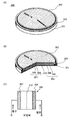
- FIG. 5A is an external view of a coin-type (single-layer flat type) secondary battery
- FIG. 5B is a cross-sectional view thereof.
- a positive electrode can 301 also serving as a positive electrode terminal and a negative electrode can 302 also serving as a negative electrode terminal are insulated and sealed with a gasket 303 formed of polypropylene or the like.
- the positive electrode 304 is formed by a positive electrode current collector 305 and a positive electrode active material layer 306 provided so as to be in contact therewith.
- the negative electrode 307 is formed of a negative electrode current collector 308 and a negative electrode active material layer 309 provided so as to be in contact therewith.
- each of the positive electrode 304 and the negative electrode 307 used in the coin-type secondary battery 300 may have an active material layer formed only on one side.
- the positive electrode can 301 and the negative electrode can 302 a metal such as nickel, aluminum, titanium, or the like having corrosion resistance to the electrolytic solution, or an alloy thereof or an alloy of these with another metal (for example, stainless steel) is used. it can. In order to prevent corrosion due to the electrolytic solution, it is preferable to coat nickel, aluminum, or the like.
- the positive electrode can 301 and the negative electrode can 302 are electrically connected to the positive electrode 304 and the negative electrode 307, respectively.
- the negative electrode 307, the positive electrode 304, and the separator 310 are impregnated in an electrolyte, and the positive electrode 304, the separator 310, the negative electrode 307, and the negative electrode can 302 are laminated in this order with the positive electrode can 301 facing down, as shown in FIG. Then, the positive electrode can 301 and the negative electrode can 302 are pressure-bonded via a gasket 303 to manufacture a CR2032-type (diameter 20 mm, height 3.2 mm) coin-shaped secondary battery 300.
- the flow of current when the secondary battery is charged will be described with reference to FIG.
- a secondary battery using lithium is regarded as one closed circuit
- the movement of lithium ions and the flow of current are in the same direction.
- the anode (anode) and the cathode (cathode) are interchanged by charging and discharging, and the oxidation reaction and the reduction reaction are interchanged. Therefore, the electrode having a high reaction potential is called the positive electrode.
- An electrode having a low reaction potential is called a negative electrode. Therefore, in the present specification, the positive electrode is referred to as “positive electrode” or “whether the battery is being charged, discharged, a reverse pulse current is applied, or a charge current is applied.
- the positive electrode is referred to as a “positive electrode”, and the negative electrode is referred to as a “negative electrode” or a “ ⁇ electrode (negative electrode)”.
- the terms anode (anode) and cathode (cathode) related to the oxidation reaction or reduction reaction are used, the charge and discharge are reversed, which may cause confusion. Therefore, the terms anode (anode) and cathode (cathode) are not used in this specification. If the terms anode (anode) or cathode (cathode) are used, specify whether charging or discharging, and indicate whether it corresponds to the positive electrode (positive electrode) or the negative electrode (negative electrode). To do.
- a charger is connected to the two terminals illustrated in FIG. 5C, and the secondary battery 300 is charged. As charging of the secondary battery 300 proceeds, the potential difference between the electrodes increases.
- the battery flows from the external terminal of the secondary battery 300 toward the positive electrode 304, flows from the positive electrode 304 toward the negative electrode 307 in the secondary battery 300, and flows from the negative electrode 307 to the secondary battery 300.
- the direction of the current flowing toward the external terminal is positive. That is, the direction in which the charging current flows is the current direction.
- the coin-type secondary battery 300 having excellent cycle characteristics can be obtained.
- an aluminum foil coated with carbon is used as a current collector, and a lithium foil is used as a negative electrode.
- polypropylene is used as a separator, 1 mol / L lithium hexafluorophosphate (LiPF 6 ) is used as one component of the electrolytic solution, and ethylene carbonate (EC) and diethyl carbonate (DEC) are used as the components of the other electrolytic solutions.
- EC mol / L lithium hexafluorophosphate
- DEC diethyl carbonate
- a slurry in which the positive electrode active material described in the above embodiment, acetylene black (AB), and polyvinylidene fluoride (PVDF) are mixed at LCO: AB: PVDF 95: 3: 2 (weight ratio) is collected.
- the one coated on the electric body was used. Drying was performed at 80 ° C. and press treatment was performed at a pressure of 210 kN / m.
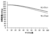
- Sample 1 GO is 0.5 wt% (LATP is 5 wt%)
- Sample 2 GO is 0.2 wt% (LATP is 5 wt%)
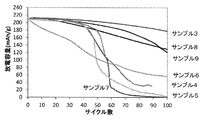
- Sample 3 LATP is 2 wt% (GO is 0.5 wt%)
- Sample 4 4 wt% LATP (GO is 0.5 wt%)
- Sample 5 8 wt% LATP (GO is 0.5 wt%)
- Sample 6 No GO, no LATP
- Sample 7 GO 0.5 wt%, no LATP
- Sample 8 LATP 0.2 wt% (GO is 0.5 wt%)
- Sample 9 LATP 0.5 wt% (GO 0.5 wt%)
- Samples 5 and 6 are comparative examples.
- charging was performed with CC / CV, 1.0C, 4.55V, 0.05C cutoff, and discharging was performed with CC, 1.0C, 3.0V cutoff.
- the measurement temperature for cycle characteristics was 45 ° C., and 100 cycles were measured. The results are shown in FIG. From the results of FIG. 7, the cycle characteristics of Sample 3 in which LATP was 2 wt% were better than those of other samples.
- Sample 3 had an initial discharge capacity of about 210 mAh / g, about 177 mAh / g even after 100 cycles, and a discharge capacity retention rate of 83.8%.
- charging / discharging of a secondary battery can be performed as follows, for example.
- CC charging is a charging method in which a constant current is supplied to the secondary battery throughout the charging period and charging is stopped when a predetermined voltage is reached.
- the secondary battery is assumed to be an equivalent circuit of an internal resistance R and a secondary battery capacity C as shown in FIG.
- the secondary battery voltage V B is the sum of the voltage V C applied to the voltage V R and the secondary battery capacity C according to the internal resistance R.
- the switch is turned on, and a constant current I flows through the secondary battery.
- the voltage V C applied to the secondary battery capacity C increases with time. Therefore, the secondary battery voltage V B increases with time.
- FIG. 8C shows an example of the secondary battery voltage V B and the charging current during the CC charging and after the CC charging is stopped. It is shown that the secondary battery voltage B , which has been increasing during the CC charging, slightly decreases after the CC charging is stopped.
- CCCV charging is a charging method in which charging is first performed up to a predetermined voltage by CC charging, and then charging is performed until the current flowing through CV (constant voltage) charging is reduced, specifically until the end current value is reached. .
- the constant current power source switch is turned on, the constant voltage power source switch is turned off, and a constant current I flows through the secondary battery.
- the voltage V C applied to the secondary battery capacity C increases with time. Therefore, the secondary battery voltage V B increases with time.
- the secondary battery voltage V B is has reached a predetermined voltage, for example 4.3 V, switching from CC charging to CV charging.
- a predetermined voltage for example 4.3 V
- the constant voltage power source switch is turned on, the constant current power source switch is turned off, and the secondary battery voltage V B becomes constant.
- FIG. 9D shows an example of the secondary battery voltage V B and the charging current during the CCCV charging and after the CCCV charging is stopped. It is shown that the secondary battery voltage V B hardly decreases even when CCCV charging is stopped.
- CC discharge which is one of the discharge methods, will be described.
- CC discharge constant current in all the discharge period flowed from the secondary battery, a discharge process for stopping the discharge when the secondary battery voltage V B is has reached a predetermined voltage, for example 2.5V.
- the discharge rate is the relative ratio of the current during discharge to the battery capacity, and is expressed in units C.
- the current corresponding to 1 C is X (A).
- X (A) When discharged at a current of 2X (A), it is said that it was discharged at 2C, and when discharged at a current of X / 5 (A), it was discharged at 0.2C.
- the charging rate is also the same.
Landscapes
- Chemical & Material Sciences (AREA)
- Chemical Kinetics & Catalysis (AREA)
- Electrochemistry (AREA)
- General Chemical & Material Sciences (AREA)
- Engineering & Computer Science (AREA)
- Inorganic Chemistry (AREA)
- Manufacturing & Machinery (AREA)
- Composite Materials (AREA)
- Materials Engineering (AREA)
- Battery Electrode And Active Subsutance (AREA)
- Advance Control (AREA)
- Executing Machine-Instructions (AREA)
- Devices For Executing Special Programs (AREA)
- Secondary Cells (AREA)
- Electric Double-Layer Capacitors Or The Like (AREA)
Abstract
Description
図1に工程フロー図を示す。

本実施の形態では、車両に本発明の一態様である二次電池を搭載する例を示す。
サンプル1:GOは0.5wt%(LATPを5wt%)
サンプル2:GOは0.2wt%(LATPを5wt%)
サンプル3:LATPを2wt%(GOは0.5wt%)
サンプル4:LATPを4wt%(GOは0.5wt%)
サンプル5:LATPを8wt%(GOは0.5wt%)
サンプル6:GOなし、LATPなし
サンプル7:GO0.5wt%、LATPなし
サンプル8:LATPを0.2wt%(GOは0.5wt%)
サンプル9:LATPを0.5wt%(GOは0.5wt%)
次に、上記で作製したサンプル1、2の二次電池のサイクル特性の評価を行った。結果を図6に示す。図6の結果から、GOは、0.2wt%よりも0.5wt%としたサンプル1のサイクル特性が良好であった。
なお、二次電池の充放電は、たとえば下記のように行うことができる。
Claims (10)
- リチウムと遷移金属元素と酸素を有するリチウム化合物粒子と、グラフェン化合物と、固体電解質と、溶媒とを含む懸濁液を噴霧し、
加熱により表面に含まれる炭素を炭酸ガスに変えて揮散させて正極活物質粒子を作製する方法。 - 請求項1において、前記噴霧はスプレーノズルを用いることを特徴とする正極活物質粒子を作製する方法。
- 請求項1において、前記固体電解質はNASICON型のリン酸化合物である正極活物質粒子を作製する方法。
- 請求項1において、前記溶媒は、水およびエタノールである正極活物質粒子を作製する方法。
- 請求項1において、前記加熱は大気雰囲気下で前記固体電解質の融点以上の温度で行う正極活物質粒子を作製する方法。
- 請求項1において、前記遷移金属はコバルトである正極活物質粒子を作製する方法。
- リチウムと遷移金属元素と酸素を有するリチウム化合物粒子と、該リチウム化合物粒子に接するリン酸化合物とを有する正極と、
前記リチウム化合物粒子及び前記リン酸化合物と接する電解液と、
負極とを有する二次電池。 - リチウムと遷移金属元素と酸素を有するリチウム化合物粒子と、該リチウム化合物粒子に接する保護層とを有する正極と、
前記保護層と接する電解液と、
負極とを有し、
前記保護層は炭素を含む二次電池。 - 請求項7または請求項8において、前記リチウム化合物粒子は、マグネシウムとフッ素を有し、前記マグネシウムまたは前記フッ素が前記リチウム化合物粒子の内部と比べて前記リチウム化合物粒子の表面に高濃度に含まれる勾配を有することを特徴とする二次電池。
- 請求項7または請求項8において、前記リチウム化合物粒子は、チタンを含む二次電池。
Priority Applications (7)
| Application Number | Priority Date | Filing Date | Title |
|---|---|---|---|
| KR1020197035788A KR102685436B1 (ko) | 2017-05-03 | 2018-04-19 | 양극 활물질 입자의 제작 방법 및 이차 전지 |
| JP2019516295A JP7092752B2 (ja) | 2017-05-03 | 2018-04-19 | 正極活物質粒子の作製方法 |
| US16/609,621 US20200152961A1 (en) | 2017-05-03 | 2018-04-19 | Method for Manufacturing Positive Electrode Active Material Particles and Secondary Battery |
| CN201880029345.6A CN110603673B (zh) | 2017-05-03 | 2018-04-19 | 正极活性物质的制造方法以及二次电池 |
| JP2022097411A JP2022113870A (ja) | 2017-05-03 | 2022-06-16 | 二次電池 |
| US18/221,776 US20230361267A1 (en) | 2017-05-03 | 2023-07-13 | Method for Manufacturing Positive Electrode Active Material Particles and Secondary Battery |
| JP2024008552A JP2024032847A (ja) | 2017-05-03 | 2024-01-24 | 二次電池 |
Applications Claiming Priority (2)
| Application Number | Priority Date | Filing Date | Title |
|---|---|---|---|
| JP2017092039 | 2017-05-03 | ||
| JP2017-092039 | 2017-05-03 |
Related Child Applications (2)
| Application Number | Title | Priority Date | Filing Date |
|---|---|---|---|
| US16/609,621 A-371-Of-International US20200152961A1 (en) | 2017-05-03 | 2018-04-19 | Method for Manufacturing Positive Electrode Active Material Particles and Secondary Battery |
| US18/221,776 Division US20230361267A1 (en) | 2017-05-03 | 2023-07-13 | Method for Manufacturing Positive Electrode Active Material Particles and Secondary Battery |
Publications (1)
| Publication Number | Publication Date |
|---|---|
| WO2018203168A1 true WO2018203168A1 (ja) | 2018-11-08 |
Family
ID=64015988
Family Applications (1)
| Application Number | Title | Priority Date | Filing Date |
|---|---|---|---|
| PCT/IB2018/052700 Ceased WO2018203168A1 (ja) | 2017-05-03 | 2018-04-19 | 正極活物質粒子の作製方法、および二次電池 |
Country Status (5)
| Country | Link |
|---|---|
| US (2) | US20200152961A1 (ja) |
| JP (3) | JP7092752B2 (ja) |
| KR (1) | KR102685436B1 (ja) |
| CN (1) | CN110603673B (ja) |
| WO (1) | WO2018203168A1 (ja) |
Cited By (8)
| Publication number | Priority date | Publication date | Assignee | Title |
|---|---|---|---|---|
| US20210167368A1 (en) * | 2019-11-28 | 2021-06-03 | Semiconductor Energy Laboratory Co., Ltd. | Positive electrode active material, secondary battery, and electronic device |
| JPWO2021240292A1 (ja) * | 2020-05-29 | 2021-12-02 | ||
| KR20230097054A (ko) | 2020-10-26 | 2023-06-30 | 가부시키가이샤 한도오따이 에네루기 켄큐쇼 | 양극 활물질의 제작 방법, 양극, 이차 전지, 전자 기기, 축전 시스템, 및 차량 |
| KR20230118554A (ko) | 2020-12-11 | 2023-08-11 | 가부시키가이샤 한도오따이 에네루기 켄큐쇼 | 양극, 양극의 제작 방법, 이차 전지, 전자 기기, 축전 시스템, 및 차량 |
| KR20230138499A (ko) | 2021-02-05 | 2023-10-05 | 가부시키가이샤 한도오따이 에네루기 켄큐쇼 | 양극 활물질의 제작 방법, 이차 전지, 및 차량 |
| KR20230156083A (ko) | 2021-03-09 | 2023-11-13 | 가부시키가이샤 한도오따이 에네루기 켄큐쇼 | 복합 산화물의 제작 방법, 양극, 리튬 이온 이차 전지, 전자 기기, 축전 시스템, 및 이동체 |
| KR20240011717A (ko) | 2021-05-21 | 2024-01-26 | 가부시키가이샤 한도오따이 에네루기 켄큐쇼 | 양극 활물질의 제작 방법, 양극, 리튬 이온 이차 전지, 이동체, 축전 시스템, 및 전자 기기 |
| KR20260020384A (ko) | 2023-06-02 | 2026-02-11 | 가부시키가이샤 한도오따이 에네루기 켄큐쇼 | 이차 전지, 전자 기기, 및 차량 |
Families Citing this family (16)
| Publication number | Priority date | Publication date | Assignee | Title |
|---|---|---|---|---|
| CN116544491A (zh) | 2016-07-05 | 2023-08-04 | 株式会社半导体能源研究所 | 锂离子二次电池 |
| US12308421B2 (en) | 2016-09-12 | 2025-05-20 | Semiconductor Energy Laboratory Co., Ltd. | Electrode and power storage device comprising graphene compound |
| KR102530225B1 (ko) | 2016-10-12 | 2023-05-08 | 가부시키가이샤 한도오따이 에네루기 켄큐쇼 | 양극 활물질 입자 및 양극 활물질 입자의 제작 방법 |
| US20180145317A1 (en) * | 2016-11-18 | 2018-05-24 | Semiconductor Energy Laboratory Co., Ltd. | Positive electrode active material, method for manufacturing positive electrode active material, and secondary battery |
| CN115966675A (zh) * | 2016-11-24 | 2023-04-14 | 株式会社半导体能源研究所 | 正极活性物质粒子及正极活性物质粒子的制造方法 |
| KR102469162B1 (ko) | 2017-05-12 | 2022-11-22 | 가부시키가이샤 한도오따이 에네루기 켄큐쇼 | 양극 활물질 입자 |
| KR102656986B1 (ko) | 2017-05-19 | 2024-04-11 | 가부시키가이샤 한도오따이 에네루기 켄큐쇼 | 양극 활물질, 양극 활물질의 제작 방법, 및 이차 전지 |
| KR102529616B1 (ko) | 2017-06-26 | 2023-05-04 | 가부시키가이샤 한도오따이 에네루기 켄큐쇼 | 양극 활물질의 제작 방법 및 이차 전지 |
| KR20250048814A (ko) | 2018-06-22 | 2025-04-10 | 가부시키가이샤 한도오따이 에네루기 켄큐쇼 | 양극 활물질, 양극, 이차 전지, 및 양극의 제작 방법 |
| KR102371918B1 (ko) * | 2020-02-20 | 2022-03-08 | 한국세라믹기술원 | 양극재-고체전해질 복합체 분말의 제조방법 |
| CN115803910A (zh) * | 2020-07-14 | 2023-03-14 | 株式会社半导体能源研究所 | 电极、二次电池、移动体、电子设备以及用于锂离子二次电池的电极的制造方法 |
| CN111933928B (zh) * | 2020-08-18 | 2022-08-05 | 中国科学院宁波材料技术与工程研究所 | 一种石墨烯包覆的镍锰酸锂正极材料及其制备方法 |
| JPWO2022244416A1 (ja) * | 2021-05-20 | 2022-11-24 | ||
| CN113964377B (zh) * | 2021-09-28 | 2024-04-19 | 安普瑞斯(无锡)有限公司 | 一种固态电解质及其制备方法 |
| JP2025076257A (ja) * | 2023-10-31 | 2025-05-15 | 株式会社オハラ | 無機粒子分散スラリー、電極シート、電解質シートおよびリチウムイオン電池 |
| JP7796271B1 (ja) * | 2025-02-27 | 2026-01-08 | 株式会社オハラ | 無機酸化物粉体、および、それを含む電極あるいは電解質層を備えるリチウムイオン二次電池 |
Citations (9)
| Publication number | Priority date | Publication date | Assignee | Title |
|---|---|---|---|---|
| JP2004363097A (ja) * | 2003-05-15 | 2004-12-24 | Nichia Chem Ind Ltd | 非水電解質二次電池用正極活物質および非水電解質二次電池 |
| JP2005158612A (ja) * | 2003-11-27 | 2005-06-16 | Nichia Chem Ind Ltd | 非水電解質二次電池用正極副活物質、非水電解質二次電池用正極活物質、非水電解質二次電池および非水電解質二次電池の製造方法 |
| JP2012099468A (ja) * | 2010-10-08 | 2012-05-24 | Semiconductor Energy Lab Co Ltd | 正極活物質、及び蓄電装置 |
| JP2012169217A (ja) * | 2011-02-16 | 2012-09-06 | Asahi Glass Co Ltd | リチウムイオン二次電池用の正極活物質およびその製造方法 |
| WO2012165422A1 (ja) * | 2011-05-31 | 2012-12-06 | 日本ゼオン株式会社 | リチウム二次電池正極用複合粒子、リチウム二次電池正極用複合粒子の製造方法、リチウム二次電池用正極の製造方法、リチウム二次電池用正極、及びリチウム二次電池 |
| JP2012256591A (ja) * | 2011-05-18 | 2012-12-27 | Fuji Heavy Ind Ltd | 蓄電デバイス及び蓄電デバイス用正極 |
| JP2015220123A (ja) * | 2014-05-19 | 2015-12-07 | トヨタ自動車株式会社 | 非水電解質二次電池およびその製造方法 |
| JP2016189321A (ja) * | 2015-03-27 | 2016-11-04 | Tdk株式会社 | リチウムイオン二次電池用正極活物質、リチウムイオン二次電池用正極およびこれを用いたリチウムイオン二次電池 |
| JP2018092934A (ja) * | 2016-12-02 | 2018-06-14 | 株式会社半導体エネルギー研究所 | 電極、電極の製造方法および蓄電装置 |
Family Cites Families (19)
| Publication number | Priority date | Publication date | Assignee | Title |
|---|---|---|---|---|
| JP2003173777A (ja) * | 2001-12-07 | 2003-06-20 | Hitachi Metals Ltd | 非水系リチウム二次電池用正極活物質と導電助材の複合方法およびその複合材料、それを用いた正極および非水系リチウム二次電池 |
| US8592090B2 (en) * | 2004-08-18 | 2013-11-26 | Central Research Institute Of Electric Power Industry | Solid polymer electrolyte battery and method for manufacturing positive electrode sheet used therein |
| CN101465418B (zh) * | 2007-12-19 | 2011-06-15 | 比亚迪股份有限公司 | 一种锂离子二次电池用正极复合材料的制备方法 |
| CN102171864A (zh) | 2008-12-24 | 2011-08-31 | 日本碍子株式会社 | 锂二次电池的正极活性物质用的板状粒子、同物质膜及锂二次电池 |
| US9325001B2 (en) * | 2011-02-02 | 2016-04-26 | Toyota Jidosha Kabushiki Kaisha | Composite active material, method for producing composite active material, and battery |
| WO2013073038A1 (ja) * | 2011-11-17 | 2013-05-23 | トヨタ自動車株式会社 | 電解質被覆型正極活物質粒子、全固体電池、および電解質被覆型正極活物質粒子の製造方法 |
| JP6016597B2 (ja) * | 2011-12-16 | 2016-10-26 | 株式会社半導体エネルギー研究所 | リチウムイオン二次電池用正極の製造方法 |
| JP6009343B2 (ja) * | 2011-12-26 | 2016-10-19 | 株式会社半導体エネルギー研究所 | 二次電池用正極および二次電池用正極の作製方法 |
| JP2013161529A (ja) * | 2012-02-01 | 2013-08-19 | Toyota Motor Corp | 固体電池用電極層の製造方法及び固体電池用電極体の製造装置 |
| WO2013132663A1 (ja) * | 2012-03-09 | 2013-09-12 | トヨタ自動車株式会社 | 非水電解液二次電池 |
| JP5828304B2 (ja) * | 2012-06-29 | 2015-12-02 | トヨタ自動車株式会社 | 複合活物質、固体電池および複合活物質の製造方法 |
| WO2014181784A1 (ja) * | 2013-05-07 | 2014-11-13 | Dowaホールディングス株式会社 | 正極活物質粉末およびその製造方法 |
| WO2016063607A1 (ja) * | 2014-10-20 | 2016-04-28 | アルプス電気株式会社 | 固体電解質粉末、全固体リチウムイオン二次電池、及び固体電解質粉末の製造方法 |
| JP2017004672A (ja) * | 2015-06-08 | 2017-01-05 | セイコーエプソン株式会社 | 電極複合体、電極複合体の製造方法およびリチウム電池 |
| CN115966675A (zh) * | 2016-11-24 | 2023-04-14 | 株式会社半导体能源研究所 | 正极活性物质粒子及正极活性物质粒子的制造方法 |
| KR102469162B1 (ko) * | 2017-05-12 | 2022-11-22 | 가부시키가이샤 한도오따이 에네루기 켄큐쇼 | 양극 활물질 입자 |
| KR20250048814A (ko) * | 2018-06-22 | 2025-04-10 | 가부시키가이샤 한도오따이 에네루기 켄큐쇼 | 양극 활물질, 양극, 이차 전지, 및 양극의 제작 방법 |
| KR20260027273A (ko) * | 2018-11-21 | 2026-02-27 | 가부시키가이샤 한도오따이 에네루기 켄큐쇼 | 양극 활물질 및 이차 전지 |
| KR20260051460A (ko) * | 2018-12-17 | 2026-04-16 | 가부시키가이샤 한도오따이 에네루기 켄큐쇼 | 양극 활물질 및 이차 전지 |
-
2018
- 2018-04-19 US US16/609,621 patent/US20200152961A1/en not_active Abandoned
- 2018-04-19 JP JP2019516295A patent/JP7092752B2/ja not_active Expired - Fee Related
- 2018-04-19 KR KR1020197035788A patent/KR102685436B1/ko active Active
- 2018-04-19 CN CN201880029345.6A patent/CN110603673B/zh active Active
- 2018-04-19 WO PCT/IB2018/052700 patent/WO2018203168A1/ja not_active Ceased
-
2022
- 2022-06-16 JP JP2022097411A patent/JP2022113870A/ja not_active Withdrawn
-
2023
- 2023-07-13 US US18/221,776 patent/US20230361267A1/en not_active Abandoned
-
2024
- 2024-01-24 JP JP2024008552A patent/JP2024032847A/ja not_active Withdrawn
Patent Citations (9)
| Publication number | Priority date | Publication date | Assignee | Title |
|---|---|---|---|---|
| JP2004363097A (ja) * | 2003-05-15 | 2004-12-24 | Nichia Chem Ind Ltd | 非水電解質二次電池用正極活物質および非水電解質二次電池 |
| JP2005158612A (ja) * | 2003-11-27 | 2005-06-16 | Nichia Chem Ind Ltd | 非水電解質二次電池用正極副活物質、非水電解質二次電池用正極活物質、非水電解質二次電池および非水電解質二次電池の製造方法 |
| JP2012099468A (ja) * | 2010-10-08 | 2012-05-24 | Semiconductor Energy Lab Co Ltd | 正極活物質、及び蓄電装置 |
| JP2012169217A (ja) * | 2011-02-16 | 2012-09-06 | Asahi Glass Co Ltd | リチウムイオン二次電池用の正極活物質およびその製造方法 |
| JP2012256591A (ja) * | 2011-05-18 | 2012-12-27 | Fuji Heavy Ind Ltd | 蓄電デバイス及び蓄電デバイス用正極 |
| WO2012165422A1 (ja) * | 2011-05-31 | 2012-12-06 | 日本ゼオン株式会社 | リチウム二次電池正極用複合粒子、リチウム二次電池正極用複合粒子の製造方法、リチウム二次電池用正極の製造方法、リチウム二次電池用正極、及びリチウム二次電池 |
| JP2015220123A (ja) * | 2014-05-19 | 2015-12-07 | トヨタ自動車株式会社 | 非水電解質二次電池およびその製造方法 |
| JP2016189321A (ja) * | 2015-03-27 | 2016-11-04 | Tdk株式会社 | リチウムイオン二次電池用正極活物質、リチウムイオン二次電池用正極およびこれを用いたリチウムイオン二次電池 |
| JP2018092934A (ja) * | 2016-12-02 | 2018-06-14 | 株式会社半導体エネルギー研究所 | 電極、電極の製造方法および蓄電装置 |
Cited By (11)
| Publication number | Priority date | Publication date | Assignee | Title |
|---|---|---|---|---|
| US20210167368A1 (en) * | 2019-11-28 | 2021-06-03 | Semiconductor Energy Laboratory Co., Ltd. | Positive electrode active material, secondary battery, and electronic device |
| US11936036B2 (en) * | 2019-11-28 | 2024-03-19 | Semiconductor Energy Laboratory Co., Ltd. | Positive electrode active material, secondary battery, and electronic device |
| US12244007B2 (en) | 2019-11-28 | 2025-03-04 | Semiconductor Energy Laboratory Co., Ltd. | Positive electrode active material, secondary battery, and electronic device |
| JPWO2021240292A1 (ja) * | 2020-05-29 | 2021-12-02 | ||
| WO2021240292A1 (ja) * | 2020-05-29 | 2021-12-02 | 株式会社半導体エネルギー研究所 | 二次電池および二次電池を有する車両 |
| KR20230097054A (ko) | 2020-10-26 | 2023-06-30 | 가부시키가이샤 한도오따이 에네루기 켄큐쇼 | 양극 활물질의 제작 방법, 양극, 이차 전지, 전자 기기, 축전 시스템, 및 차량 |
| KR20230118554A (ko) | 2020-12-11 | 2023-08-11 | 가부시키가이샤 한도오따이 에네루기 켄큐쇼 | 양극, 양극의 제작 방법, 이차 전지, 전자 기기, 축전 시스템, 및 차량 |
| KR20230138499A (ko) | 2021-02-05 | 2023-10-05 | 가부시키가이샤 한도오따이 에네루기 켄큐쇼 | 양극 활물질의 제작 방법, 이차 전지, 및 차량 |
| KR20230156083A (ko) | 2021-03-09 | 2023-11-13 | 가부시키가이샤 한도오따이 에네루기 켄큐쇼 | 복합 산화물의 제작 방법, 양극, 리튬 이온 이차 전지, 전자 기기, 축전 시스템, 및 이동체 |
| KR20240011717A (ko) | 2021-05-21 | 2024-01-26 | 가부시키가이샤 한도오따이 에네루기 켄큐쇼 | 양극 활물질의 제작 방법, 양극, 리튬 이온 이차 전지, 이동체, 축전 시스템, 및 전자 기기 |
| KR20260020384A (ko) | 2023-06-02 | 2026-02-11 | 가부시키가이샤 한도오따이 에네루기 켄큐쇼 | 이차 전지, 전자 기기, 및 차량 |
Also Published As
| Publication number | Publication date |
|---|---|
| US20230361267A1 (en) | 2023-11-09 |
| JP2022113870A (ja) | 2022-08-04 |
| JP2024032847A (ja) | 2024-03-12 |
| KR20190140072A (ko) | 2019-12-18 |
| JP7092752B2 (ja) | 2022-06-28 |
| JPWO2018203168A1 (ja) | 2020-03-26 |
| CN110603673B (zh) | 2025-03-07 |
| CN110603673A (zh) | 2019-12-20 |
| KR102685436B1 (ko) | 2024-07-15 |
| US20200152961A1 (en) | 2020-05-14 |
Similar Documents
| Publication | Publication Date | Title |
|---|---|---|
| JP7092752B2 (ja) | 正極活物質粒子の作製方法 | |
| KR102807187B1 (ko) | 리튬 이온 2차 전지용 음극의 제조 방법 | |
| US11962013B2 (en) | Positive electrode for secondary battery and manufacturing method of positive electrode for secondary battery | |
| JP7010913B2 (ja) | 非水系リチウム二次電池用正極の作製方法 | |
| CN100544107C (zh) | 蓄电池系统、车载电源系统、车辆和蓄电池系统的充电方法 | |
| CN100524933C (zh) | 非水电解质电池、电池组和汽车 | |
| JP2023123505A (ja) | 活物質層及び二次電池 | |
| JP5149927B2 (ja) | リチウム二次電池用正極材料、リチウム二次電池及びそれを用いた二次電池モジュール | |
| JP2019079817A (ja) | 電子機器 | |
| CN111710870B (zh) | 电极的制造方法、电极、蓄电池及电子设备 | |
| CN108631007A (zh) | 二次电池、电池包及车辆 | |
| JP2007048525A (ja) | 非水電解質リチウムイオン電池用正極材料およびこれを用いた電池 | |
| CN102347484B (zh) | 电池用活性物质、非水电解质电池、电池包以及汽车 | |
| CN107210479A (zh) | 电气设备 | |
| WO2021130610A1 (ja) | 正極活物質層、活物質層、正極、二次電池および車両 | |
| CN108630906A (zh) | 活性物质、电极、二次电池、组电池、电池包及车辆 | |
| JP5880942B2 (ja) | 非水電解液二次電池 | |
| JP7858563B2 (ja) | ニオブチタン系酸化物、電極、二次電池、電池パック、車両、及び定置用電源 | |
| JP7248136B2 (ja) | リチウムイオン二次電池用正極活物質 | |
| WO2023119056A1 (ja) | 前駆体の製造方法、及び正極活物質の製造方法 | |
| WO2023062473A1 (ja) | バッテリ制御システム及び車両 |
Legal Events
| Date | Code | Title | Description |
|---|---|---|---|
| 121 | Ep: the epo has been informed by wipo that ep was designated in this application |
Ref document number: 18794204 Country of ref document: EP Kind code of ref document: A1 |
|
| ENP | Entry into the national phase |
Ref document number: 2019516295 Country of ref document: JP Kind code of ref document: A |
|
| NENP | Non-entry into the national phase |
Ref country code: DE |
|
| ENP | Entry into the national phase |
Ref document number: 20197035788 Country of ref document: KR Kind code of ref document: A |
|
| 122 | Ep: pct application non-entry in european phase |
Ref document number: 18794204 Country of ref document: EP Kind code of ref document: A1 |
|
| WWG | Wipo information: grant in national office |
Ref document number: 201880029345.6 Country of ref document: CN |