WO2018139573A1 - 電解コンデンサ用電解液、電解コンデンサ、及び電解コンデンサの製造方法 - Google Patents
電解コンデンサ用電解液、電解コンデンサ、及び電解コンデンサの製造方法 Download PDFInfo
- Publication number
- WO2018139573A1 WO2018139573A1 PCT/JP2018/002418 JP2018002418W WO2018139573A1 WO 2018139573 A1 WO2018139573 A1 WO 2018139573A1 JP 2018002418 W JP2018002418 W JP 2018002418W WO 2018139573 A1 WO2018139573 A1 WO 2018139573A1
- Authority
- WO
- WIPO (PCT)
- Prior art keywords
- group
- silica
- silane coupling
- electrolytic capacitor
- coupling agent
- Prior art date
- Legal status (The legal status is an assumption and is not a legal conclusion. Google has not performed a legal analysis and makes no representation as to the accuracy of the status listed.)
- Ceased
Links
Classifications
-
- H—ELECTRICITY
- H01—ELECTRIC ELEMENTS
- H01G—CAPACITORS; CAPACITORS, RECTIFIERS, DETECTORS, SWITCHING DEVICES, LIGHT-SENSITIVE OR TEMPERATURE-SENSITIVE DEVICES OF THE ELECTROLYTIC TYPE
- H01G9/00—Electrolytic capacitors, rectifiers, detectors, switching devices, light-sensitive or temperature-sensitive devices; Processes of their manufacture
-
- H—ELECTRICITY
- H01—ELECTRIC ELEMENTS
- H01G—CAPACITORS; CAPACITORS, RECTIFIERS, DETECTORS, SWITCHING DEVICES, LIGHT-SENSITIVE OR TEMPERATURE-SENSITIVE DEVICES OF THE ELECTROLYTIC TYPE
- H01G9/00—Electrolytic capacitors, rectifiers, detectors, switching devices, light-sensitive or temperature-sensitive devices; Processes of their manufacture
- H01G9/004—Details
- H01G9/022—Electrolytes; Absorbents
- H01G9/035—Liquid electrolytes, e.g. impregnating materials
Definitions
- the present invention relates to an electrolytic solution for an electrolytic capacitor, an electrolytic capacitor, and a method for manufacturing the electrolytic capacitor.
- Electrolytic capacitors have valve action metals such as tantalum or aluminum as anode foil and cathode foil.
- the anode foil is enlarged by forming the valve metal into a shape such as a sintered body or an etching foil, and has a dielectric oxide film layer on the enlarged surface.
- An electrolytic solution is interposed between the anode foil and the cathode foil. The electrolytic solution is in close contact with the uneven surface of the anode foil and functions as a true cathode.
- the electrolytic solution is interposed between the dielectric oxide film layer of the anode foil and the cathode foil, and exchanges electrons between the anode foil and the cathode foil. Therefore, the electrical conductivity and temperature characteristics of the electrolytic solution greatly affect the electrical characteristics of the electrolytic capacitor such as impedance, dielectric loss (tan ⁇ ), and equivalent series resistance (ESR). Further, the electrolytic solution has a chemical property of repairing a deteriorated portion such as deterioration or damage of the dielectric oxide film formed on the anode foil, and affects the leakage current (LC) and life characteristics of the electrolytic capacitor.
- LC leakage current
- an electrolytic solution having at least a high electrical conductivity is suitable for the electrolytic capacitor.
- the conductivity of the electrolytic solution is increased, the spark voltage tends to decrease, and the withstand voltage characteristic of the electrolytic capacitor may be impaired.
- the electrolyte with silica modified on the surface with a silylating agent or silane coupling agent is added with silica that is not surface-modified, although gelation of the electrolyte and precipitation and aggregation of silica are suppressed.
- the present inventors have found that the effect of improving the initial withstand voltage is small compared to the electrolytic solution prepared. It is presumed that the effect of improving the initial withstand voltage is reduced because the hydroxyl group on the silica surface is modified and the affinity with the hydrophilic dielectric oxide film is lowered.
- the present invention has been proposed to solve the above-mentioned problems, and its object is to provide an electrolytic solution having a further withstand voltage effect, an electrolytic capacitor using the electrolytic solution, and a method for manufacturing the electrolytic capacitor. There is to do.
- the inventors of the present invention impregnate a capacitor element with an electrolytic solution to which surface-modified silica is added by subjecting silica to a surface modification reaction with a silylating agent or a silane coupling agent in an electrolytic capacitor. It has been found that an electrolytic capacitor having an initial breakdown voltage higher than the case can be obtained.
- silica is adsorbed on the surface of the electrode foil and becomes a resistance component, whereby the withstand voltage of the electrolytic capacitor is improved.
- the dielectric oxide film is hydrophilic, the hydroxyl group present on the silica surface and the dielectric oxide film on the electrode foil surface are considered to have high affinity. For this reason, when an electrolytic capacitor is produced using an electrolytic solution to which silica and a silylating agent or a silane coupling agent are added, in the initial stage, physical adsorption between silica having a large amount of remaining hydroxyl groups and the dielectric oxide film occurs first. Next, it is considered that a large amount of the phenomenon that the surface of the silica adsorbed on the dielectric oxide film is modified by the silylating agent or the silane coupling agent occurs in the electrolytic capacitor.
- the initial withstand voltage is improved by adsorbing silica on the surface of the electrode foil.
- the surface modification reaction of silica with the silylating agent or the silane coupling agent proceeds, and the dielectric oxide film and the silylating agent or the silane coupling agent also bind.
- the silylating agent or silane coupling agent bonded to silica and the silylating agent or silane coupling agent bonded to the dielectric oxide film increase the affinity between the dielectric oxide film and silica, and the silica approaches the dielectric oxide film. It becomes easy.
- the surface of silica is modified with a silylating agent or silane coupling agent in an electrolytic capacitor, the surface of the electrode foil combined with the silylating agent or silane coupling agent and the silica combined with the silylating agent or silane coupling agent It is considered that the improvement of the affinity and the suppression of the gelation of the electrolytic solution due to the aggregation of silica can maintain the pressure resistance after being left high.
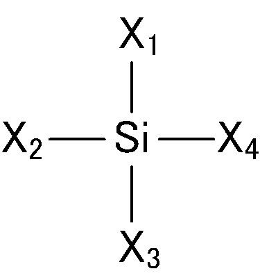
- the electrolytic solution of the present invention is for an electrolytic capacitor, and includes a solvent, a solute, silica, and a silylating agent or silane cup represented by the following general formula (Formula 1). And a ring agent.
- the silica contained in the electrolytic solution is surface-modified with the silylating agent or silane coupling agent contained in the electrolytic solution, thereby improving the initial withstand voltage and the withstand voltage after standing.
- a capacitor is obtained.
- X 1 is an alkyl group, alkenyl group, aryl group or aralkyl group having 1 to 20 carbon atoms, and a part of the hydrogen is a carboxyl group, an ester group, an amide group, a cyano group, a ketone group, A hydrocarbon group (—R) optionally substituted by a formyl group, an ether group, a hydroxyl group, an amino group, a mercapto group, a sulfide group, a sulfoxide group, a sulfone group, an isocyanate group or a ureido group.
- X 2 to X 4 are an acetoxy group, an alkoxy group having 1 to 5 carbon atoms, or an alkyl group, and at least two of X 2 to X 4 are alkoxy groups.
- the silylating agent or silane coupling agent represented by the general formula (Chemical Formula 1) is 3-glycidoxypropylmethyldimethoxysilane, 3-methacryloxypropyltriethoxysilane, 2- (3,4-epoxycyclohexyl).
- One or more selected from the group of silane and 3-glycidoxypropylmethyldiethoxysilane may be used.
- the amount of the silylating agent or silane coupling agent added to the silica may be from 1: 0.01 to 3.33 by weight. Within this range, gelation of the electrolytic solution due to aggregation of silica does not occur, and the effect of improving the withstand voltage by silica becomes remarkable.
- the present inventors have suppressed the decrease in withstand voltage over time when the amount of the silylating agent or silane coupling agent added to silica is 1: 0.03 or more by weight. It was found that an electrolytic capacitor was obtained.
- the present inventors presume this reason as follows, although the present invention is not limited to the following presumption mechanism. That is, after time elapses, the silica surface modification reaction with the silylating agent or silane coupling agent proceeds, and the silylating agent or silane coupling agent that was not involved in the surface modification of the silica is oxidized by the dielectric. It is thought that the phenomenon of bonding with the film also occurs.
- the silylating agent or silane coupling agent bonded to silica and the silylating agent or silane coupling agent bonded to the dielectric oxide film increase the affinity between the dielectric oxide film and silica, and the silica approaches the dielectric oxide film. It becomes easy.
- silica when silica is surface-modified with a silylating agent or silane coupling agent in an electrolytic capacitor, the affinity of the electrode foil surface combined with the silylating agent or silane coupling agent and the silica combined with the silylating agent or silane coupling agent It is considered that a decrease in withstand voltage with time is suppressed by a combination of the improvement of the property and the suppression of gelation of the electrolytic solution due to the aggregation of silica.
- the amount of the silylating agent or silane coupling agent added to the silica may be 1: 0.03 or more by weight. This suppresses a decrease in high initial breakdown voltage with time.
- the addition amount of the silica may be 2 wt% or more and 35 wt% or less with respect to the entire electrolytic solution for electrolytic capacitor. This suppresses a decrease in high initial withstand voltage over time, and the effect of improving the withstand voltage due to silica becomes remarkable.
- An electrolytic capacitor provided with an electrolytic solution for this electrolytic capacitor is also an embodiment of the present invention.
- the electrolytic capacitor includes a pair of electrode foils, and the silylating agent or the silane coupling agent is bonded to silica and / or the surface of the electrode foil, and the silica is present on the surface of the electrode foil. It is desirable. Moreover, it is desirable that the silica surface-modified with the silylating agent or the silane coupling agent is adsorbed on the surface of the electrode foil with a hydroxyl group.
- the silylating agent or the silane coupling agent is bonded to silica and the surface of the electrode foil, and the surface of the electrode foil is interposed through the silylating agent or the silane coupling agent. It is desirable that the silica is close.
- the term “silica is close to the electrode foil” means that the silica may be in contact with the electrode foil surface, or the silica may not be in contact with the electrode foil but may be present in the vicinity of the electrode foil surface.
- the method for producing an electrolytic capacitor of the present invention comprises forming a capacitor element by making an anode foil and a cathode foil on which a dielectric oxide film is formed face each other via a separator, and at least a solvent, a solute, silica And impregnating a silylating agent or a silane coupling agent represented by the above general formula (Formula 1).
- the silica in the electrolytic solution is surface-modified with the silylating agent or the silane coupling agent in the electrolytic solution. Is good.
- heat treatment may be performed after the step of impregnating the capacitor element with the electrolytic solution.
- the affinity between the electrolyte silica and the dielectric oxide film of the anode foil is increased, and a higher breakdown voltage improvement effect is produced while maintaining high conductivity.
- the electrolytic capacitor is a passive element that stores and discharges electric charge by electrostatic capacity.
- the electrolytic capacitor has a capacitor element in which an anode foil and a cathode foil are opposed to each other through a separator, and the capacitor element is impregnated with an electrolytic solution.
- the anode foil and the cathode foil have a porous structure on the surface, and a dielectric oxide film layer is formed at least on the porous structure portion of the anode foil.
- the electrolyte is interposed between the anode foil and the cathode foil, is in close contact with the dielectric oxide film layer of the anode foil, and becomes a true cathode that transmits the electric field of the foil.
- the separator prevents a short circuit between the anode foil and the cathode foil, and holds the electrolytic solution.
- the anode foil and the cathode foil are long foil bodies made of a valve metal.
- the valve action metal include aluminum, tantalum, niobium, niobium oxide, titanium, hafnium, zirconium, zinc, tungsten, bismuth, and antimony.
- the purity is preferably about 99.9% or more for the anode foil and about 99% or more for the cathode, but may contain impurities such as silicon, iron, copper, magnesium, and zinc.
- the anode foil and the cathode foil are a sintered body obtained by sintering a powder of a valve action metal, or an etching foil obtained by performing an etching process on a stretched foil. That is, the porous structure has tunnel-like pits, sponges, and the like. Pits or voids between dense powders.
- the porous structure is typically formed by DC etching or AC etching in which direct current or alternating current is applied in an acidic aqueous solution in which halogen ions such as hydrochloric acid are present, or metal particles or the like are deposited or sintered on the core. Is formed. Since the cathode foil has less surface area influence on the capacitance of the electrolytic capacitor than the anode foil, the surface roughness due to the porous structure may be small.
- the dielectric oxide film layer is typically an oxide film formed on the surface layer of the anode foil. If the anode foil is made of aluminum, the dielectric oxide film layer is an aluminum oxide layer obtained by oxidizing the porous structure region. Moreover, you may provide a dielectric oxide film layer in cathode foil. This dielectric oxide film layer is formed by a chemical conversion treatment in which voltage is applied in a solution free of halogen ions such as an acid such as ammonium borate, ammonium phosphate, or ammonium adipate or an aqueous solution of these acids.
- halogen ions such as an acid such as ammonium borate, ammonium phosphate, or ammonium adipate or an aqueous solution of these acids.
- Separator is made of cellulose such as kraft, manila hemp, esparto, hemp, rayon and mixed paper, polyethylene terephthalate, polybutylene terephthalate, polyethylene naphthalate, derivatives thereof such as polytetrafluoroethylene resin, polyfluoride.
- Polyamide resins such as vinylidene resins, vinylon resins, aliphatic polyamides, semi-aromatic polyamides, wholly aromatic polyamides, polyimide resins, polyethylene resins, polypropylene resins, trimethylpentene resins, polyphenylene sulfide resins, acrylic resins, etc. These resins can be used alone or in combination.
- the electrolytic solution is a mixed solution in which a solute is dissolved in a solvent and an additive is added.
- the solvent may be either a protic organic polar solvent or an aprotic organic polar solvent.
- Representative examples of the protic organic polar solvent include monohydric alcohols, polyhydric alcohols, and oxyalcohol compounds.
- Typical examples of the aprotic organic polar solvent include sulfone, amide, lactone, cyclic amide, nitrile, and oxide.
- Examples of monohydric alcohols include ethanol, propanol, butanol, pentanol, hexanol, cyclobutanol, cyclopentanol, cyclohexanol, and benzyl alcohol.
- Examples of the polyhydric alcohols and oxyalcohol compounds include ethylene glycol, propylene glycol, glycerin, methyl cellosolve, ethyl cellosolve, methoxypropylene glycol, and dimethoxypropanol.
- Examples of the sulfone type include dimethyl sulfone, ethyl methyl sulfone, diethyl sulfone, sulfolane, 3-methyl sulfolane, and 2,4-dimethyl sulfolane.
- Examples of amides include N-methylformamide, N, N-dimethylformamide, N-ethylformamide, N, N-diethylformamide, N-methylacetamide, N, N-dimethylacetamide, N-ethylacetamide, N, N- Examples include diethylacetamide and hexamethylphosphoric amide.
- lactones and cyclic amides include ⁇ -butyrolactone, ⁇ -valerolactone, ⁇ -valerolactone, N-methyl-2-pyrrolidone, ethylene carbonate, propylene carbonate, butylene carbonate, isobutylene carbonate, and isobutylene carbonate.
- nitriles include acetonitrile, 3-methoxypropionitrile, glutaronitrile and the like.
- oxides include dimethyl sulfoxide. As the solvent, these may be used alone or in combination of two or more.
- ethylene glycol has high hygroscopicity, and when a large amount of ethylene glycol is present, it is necessary to highly control the water content of the electrolyte. In this respect, if the amount of ethylene glycol in the solvent is less than 35 wt%, it is preferable because management of the moisture content of the electrolytic solution is facilitated and, for example, the possibility that the electrolytic capacitor swells during reflow is reduced.
- solute contained in the electrolytic solution examples include at least one salt of an organic acid, an inorganic acid, and a compound compound of an organic acid and an inorganic acid, which are usually used in an electrolytic solution for driving an electrolytic capacitor. These may be used alone or in combination of two or more.
- Organic acids include phthalic acid, isophthalic acid, terephthalic acid, maleic acid, adipic acid, benzoic acid, toluic acid, enanthic acid, malonic acid, 1,6-decanedicarboxylic acid, 1,7-octanedicarboxylic acid, azelaic acid , Carboxylic acids such as undecanedioic acid, dodecanedioic acid, and tridecanedioic acid, phenols, and sulfonic acid.
- inorganic acids include boric acid, phosphoric acid, phosphorous acid, hypophosphorous acid, carbonic acid, and silicic acid.
- Examples of the complex compound of an organic acid and an inorganic acid include borodisalicylic acid, borodisuccinic acid, borodiglycolic acid, and the like.
- Examples of at least one salt of an organic acid, an inorganic acid, and a compound compound of an organic acid and an inorganic acid include ammonium salts, quaternary ammonium salts, quaternized amidinium salts, amine salts, sodium salts, potassium salts, and the like. It is done.
- Examples of the quaternary ammonium ion of the quaternary ammonium salt include tetramethylammonium, triethylmethylammonium, and tetraethylammonium.
- Examples of quaternized amidinium include ethyldimethylimidazolinium and tetramethylimidazolinium.
- Examples of the amine of the amine salt include primary amines, secondary amines, and tertiary amines.
- Primary amines include methylamine, ethylamine, propylamine
- secondary amines include dimethylamine, diethylamine, ethylmethylamine, dibutylamine, etc.
- tertiary amines include trimethylamine, triethylamine, tributylamine, ethyldimethylamine, Examples thereof include ethyldiisopropylamine.
- the electrolytic solution contains silica and a silylating agent or silane coupling agent as additives.
- the silylating agent or silane coupling agent is a monomer represented by the following general formula (Formula 2).
- the silane coupling agent refers to a silylating agent or a silane coupling agent.
- X 1 is an alkyl group, alkenyl group, aryl group or aralkyl group having 1 to 20 carbon atoms, and a part of the hydrogen is a carboxyl group, an ester group, an amide group, a cyano group, a ketone group, A hydrocarbon group (—R) optionally substituted by a formyl group, an ether group, a hydroxyl group, an amino group, a mercapto group, a sulfide group, a sulfoxide group, a sulfone group, an isocyanate group or a ureido group.
- X 2 to X 4 are an acetoxy group, an alkoxy group having 1 to 5 carbon atoms, or an alkyl group, and at least two of X 2 to X 4 are alkoxy groups.
- X 1 examples include alkyl groups such as methyl group, ethyl group, propyl group, butyl group, decyl group and octadecyl group; alkenyl groups such as vinyl group and allyl group; phenyl group, naphthyl group and styryl group Aryl groups such as benzyl groups, hydrocarbon groups such as aralkyl groups such as phenethyl groups, methoxy hydrocarbon groups such as methoxy groups, ethoxy groups, propoxy groups, butoxy groups, vinyloxy groups, phenoxy groups, benzyloxy groups, etc. A hydroxyl group can be mentioned.
- acrylic groups such as 3-methacryloxypropyl group and 3-acryloxypropyl group; 3-glycidoxypropyl group, 2- (3,4-epoxycyclohexyl) ethyl group
- Epoxy groups such as; amino groups such as 3-aminopropyl group, N-phenyl-3-aminopropyl group, N-2- (aminoethyl) -3-aminopropyl group; mercapto such as 3-mercaptopropyl group Groups; isocyanate groups such as 3-isocyanatopropyl group; ureido groups such as 3-ureidopropyl group and the like.
- X 2 ⁇ X 4 a methoxy group, an ethoxy group, a propoxy group, an alkoxy group such as butoxy group; a methyl group, an ethyl group, a propyl group, a butyl group, a decyl group, an alkyl group such as an octadecyl group
- X 2 to X 4 are alkoxy groups.
- an additive other than silica, a silylating agent or a silane coupling agent may be further added to the electrolytic solution as an additive.
- an additive other than silica, a silylating agent or a silane coupling agent may be further added to the electrolytic solution as an additive.
- nitro compounds such as o-nitrobenzoic acid, m-nitrobenzoic acid, p-nitrobenzoic acid, o-nitrophenol, m-nitrophenol, p-nitrophenol, m-nitroacetophenone
- phosphoric acid Phosphorus compounds such as phosphate esters
- Such an electrolytic solution is prepared as follows. Here, a case where a silane coupling agent is used will be described, but an electrolyte can be prepared by a similar method also when a silylating agent is used.
- a solvent, a solute, silica, and a silane coupling agent are mixed to prepare an electrolytic solution.
- the order of adding the silica and the silane coupling agent to the electrolytic solution is not particularly limited, and the silane coupling agent may be added after adding the silica, or the silica may be added after adding the silane coupling agent. Further, silica and a silane coupling agent may be added simultaneously. At this point, the hydrolysis reaction of the silane coupling agent is started. If necessary, the by-product may be removed.
- this electrolytic solution is impregnated into a capacitor element, the capacitor element impregnated with the electrolytic solution is inserted into a bottomed cylindrical outer case, and the outer case is sealed with sealing rubber by crimping.
- the capacitor element may be impregnated separately with a solvent, a solute, silica, and a silane coupling agent.
- a capacitor element is first impregnated with a solution in which a solute is mixed with a solvent, then a capacitor element is impregnated with a solution in which silica is mixed with a solvent, and finally a solution in which a silane coupling agent is mixed with the solvent is added to the capacitor element. It may be impregnated.
- a capacitor element is first impregnated with a solution in which a solute is mixed with a solvent, then a capacitor element is impregnated with a solution in which a silane coupling agent is mixed with the solvent, and finally a solution in which silica is mixed with the solvent is used. May be impregnated.
- the heat treatment method is not particularly limited, and examples thereof include aging treatment and leaving at high temperature. During the aging treatment, heat is generated in the electrolytic capacitor, or the electrolytic capacitor is heated. During this heat treatment, a surface modification reaction of silica with a silane coupling agent occurs. The surface modification reaction of silica does not need to be completed, and may continue to react when an electrolytic capacitor is used.
- the dielectric oxide film of the anode foil is hydrophilic. Therefore, before heat treatment, a phenomenon that silica is physically adsorbed on the dielectric oxide film of the anode foil frequently occurs, and this silica becomes a resistance component and improves the initial withstand voltage of the electrolytic capacitor.
- the silylating agent or the silane coupling agent is bonded to each of the dielectric oxide film of the anode foil and the silica by heating. Therefore, the affinity between the dielectric oxide film of the anode foil and silica is increased through the mutual silylating agent or silane coupling agent, and even if the dielectric oxide film of the anode foil and silica are separated from each other. In addition, silica is easy to approach the dielectric oxide film.
- silica is modified with a silylating agent or a silane coupling agent, there is a lot of silica adsorbed on the dielectric oxide film, and this silica becomes a resistance component, which reduces the breakdown voltage of the electrolytic capacitor over time. Suppress.
- the addition amount of the silylating agent or the silane coupling agent to silica is desirably 1: 0.01 or more and 3.33 or less.
- the surface of the silica is modified with the silylating agent or silane coupling agent in the electrolytic solution, gelling of the electrolytic solution due to the aggregation of silica is suppressed, and the dispersion stability is improved.
- both the dielectric oxide film of the anode foil and the silica bind to the silylating agent or the silane coupling agent, and the affinity between the dielectric oxide film and the silica via the silylating agent or the silane coupling agent.
- the silica is likely to approach the dielectric oxide film. These improve the withstand voltage characteristics of the electrolytic capacitor.
- the amount of silylating agent or silane coupling agent added to silica is 1: 0.03 or more.
- Silica modified with a silane coupling agent because the silylating agent or silane coupling agent that did not participate in the surface modification reaction of the silica is present in the electrolyte and easily binds to the dielectric oxide film of the anode foil. Compared with the electrolytic solution to which only is added, a decrease in withstand voltage with time is suppressed.
- the amount of silylating agent or silane coupling agent added to silica is preferably 1: 1.67 or less. Within this range, while having good withstand voltage characteristics, the initial equivalent series resistance (ESR) of the electrolytic capacitor is within a good range, the dielectric loss tangent (tan ⁇ ) and leakage current (LC) rise is small. If the silylating agent or silane coupling agent is excessive, the amount of substances that inhibit ionic conduction increases, and it is considered that ESR deteriorates.
- the silane coupling agent that is not involved in the surface modification and silica react with the electrode foil to suppress deterioration of the dielectric oxide film due to heat. Conceivable.
- the addition amount of the silylating agent or the silane coupling agent with respect to silica exceeds 1: 1.67, the silane coupling agent and silica not involved in the surface modification are excessively deposited on the electrode foil, resulting in a resistance component. Thus, it is considered that the characteristics of tan ⁇ and LC are deteriorated.
- the amount of the silylating agent or silane coupling agent added to silica is more preferably 1: 0.84 or less.
- silica, silylating agent, and silane coupling agent are not added to the electrolyte solution while having good withstand voltage characteristics, only silica that is not surface-modified is added to the electrolyte solution.
- the capacitance change rate ( ⁇ Cap) after standing is small compared to the case where the agent and the silane coupling agent are not added and the case where only the surface-modified silica is added to the electrolytic solution, and the dielectric after standing
- the tangent change rate ( ⁇ tan ⁇ ) is also small, and the leakage current (LC) is also small.
- silane coupling agent 3-glycidoxypropylmethyldimethoxysilane, 3-methacryloxypropyltriethoxysilane, N-2- (aminoethyl) -3-aminopropylmethyldimethoxysilane, 2- ( 3,4-Epoxycyclohexyl) ethyltrimethoxysilane, vinyltrimethoxysilane, p-styryltrimethoxysilane, 3-acryloxypropyltrimethoxysilane, 3-isocyanatopropyltriethoxysilane and 3-glycidoxypropylmethyldi One or more selected from the group of ethoxysilane.
- the addition amount of silica with respect to the total amount of the electrolytic solution is not particularly limited because it does not affect the effect of suppressing the decrease in withstand voltage over time or has little influence, but the withstand voltage is 2 wt% or more and 35 wt% or less. It is preferable because it improves. If it is less than 2 wt%, the withstand voltage will be relatively low, although the effect of suppressing the withstand voltage reduction is exhibited. On the other hand, if it exceeds 35 wt%, the equivalent series resistance (ESR) and the dielectric loss tangent (tan ⁇ ) are deteriorated, although the effect of suppressing the decrease of the withstand voltage and the effect of improving the withstand voltage are seen.
- ESR equivalent series resistance
- tan ⁇ dielectric loss tangent
- Such an electrolytic capacitor is, for example, a winding type, and the capacitor element is formed by sandwiching a separator between an anode foil and a cathode foil to which a lead wire is connected and winding it.
- the capacitor element is impregnated with an electrolytic solution, and the capacitor element impregnated with the electrolytic solution is inserted into a bottomed cylindrical outer case.
- the outer case is sealed with sealing rubber by caulking.
- the electrolytic capacitor is then aged. During this aging treatment, it is considered that a surface modification reaction of silica occurs, and the surface modification reaction may not be completed at the time of producing the electrolytic capacitor, and the reaction may be performed even when the produced electrolytic capacitor is left at a high temperature. Good.
- Example 1 As Example 1 of the electrolytic capacitor according to the embodiment of the present invention, a wound electrolytic capacitor having a rated voltage of 50 WV, a rated capacity of 47 ⁇ F, a capacitor element size of 6.3 mm in diameter and 8 mm in length was manufactured.
- the surface of the aluminum foil was expanded by etching, and then an aluminum anode foil in which a dielectric oxide film layer was formed by chemical conversion was prepared. Moreover, the surface of the aluminum foil was expanded by etching treatment to produce an aluminum cathode foil. An electrode drawing means was connected to the produced anode foil and cathode foil, and a capacitor element was produced by winding with a cellulose-based separator interposed.
- the electrolyte uses 1,2,3,4-tetramethylimidazolinium phthalate (hereinafter referred to as TMIP) as a solute, ⁇ -butyrolactone and sulfolane as solvents, silica, silane coupling agent and nitro compound.
- TMIP 1,2,3,4-tetramethylimidazolinium phthalate
- ⁇ -butyrolactone and sulfolane as solvents
- silica silica
- silane coupling agent was nitro compound.
- TMIP tetramethyl-1-butane
- silica 6 wt%
- p-nitrophenol 1 wt%
- 3-glycidoxypropylmethyldimethoxysilane was 1 wt%.
- the addition amount of 3-glycidoxypropylmethyldimethoxysilane with respect to silica is 0.17 in terms of weight ratio with silica as 1.
- TMIP, silica, and p-nitrophenol were mixed with a mixed solution of ⁇ -butyrolactone and sulfolane, and 3-glycidoxypropylmethyldimethoxysilane was added to the mixed solution.
- this electrolytic solution was impregnated into the capacitor element, it was housed in a bottomed cylindrical outer case and sealed with a sealing rubber.
- each evaluation test of an evaluation test for gelation, an evaluation test for a withstand voltage characteristic, an evaluation test for various initial characteristics, and an evaluation test for various characteristics after being left unloaded is performed. went. In the following other examples and comparative examples, each evaluation test was similarly performed without performing the aging treatment.
- Example 2 The electrolytic capacitor of Example 2 was fabricated using the same material, the same method, and the same conditions as the electrolytic capacitor of Example 1. However, 3-glycidoxypropylmethyldimethoxysilane added to the electrolytic solution was 3 wt% with respect to the total amount of the electrolytic solution. The amount of 3-glycidoxypropylmethyldimethoxysilane added to silica is 0.5 in terms of the weight ratio with silica as 1.
- Example 3 The electrolytic capacitor of Example 3 was manufactured using the same material, the same method, and the same conditions as the electrolytic capacitor of Example 1. However, 3-glycidoxypropylmethyldimethoxysilane added to the electrolytic solution was 5 wt% with respect to the total amount of the electrolytic solution. The addition amount of 3-glycidoxypropylmethyldimethoxysilane with respect to silica is 0.83 in terms of weight ratio where silica is 1.
- Example 4 The electrolytic capacitor of Example 4 was fabricated using the same material, the same method, and the same conditions as the electrolytic capacitor of Example 1. However, 3-glycidoxypropylmethyldimethoxysilane added to the electrolytic solution was 10 wt% with respect to the total amount of the electrolytic solution. The amount of 3-glycidoxypropylmethyldimethoxysilane added to silica is 1.67 by weight with silica as 1.
- Example 5 The electrolytic capacitor of Example 5 was fabricated using the same material, the same method, and the same conditions as the electrolytic capacitor of Example 1. However, 3-glycidoxypropylmethyldimethoxysilane added to the electrolytic solution was 20 wt% with respect to the total amount of the electrolytic solution. The amount of 3-glycidoxypropylmethyldimethoxysilane added to silica is 3.33 in terms of a weight ratio with silica as 1.
- Example 6 The electrolytic capacitor of Example 6 was fabricated using the same material, the same method, and the same conditions as the electrolytic capacitor of Example 1. However, 3-methacryloxypropyltriethoxysilane (KBE-503 manufactured by Shin-Etsu Silicone) was added to the electrolyte as a silane coupling agent. The amount of 3-methacryloxypropyltriethoxysilane was 1 wt% with respect to the total amount of the electrolytic solution. The addition amount of 3-methacryloxypropyltriethoxysilane with respect to silica is 0.17 in terms of weight ratio where silica is 1.
- Example 7 The electrolytic capacitor of Example 7 was fabricated using the same material, the same method, and the same conditions as the electrolytic capacitor of Example 1. However, N-2- (aminoethyl) -3-aminopropylmethyldimethoxysilane (KBM-602 made by Shin-Etsu Silicone) was added to the electrolyte as a silane coupling agent. N-2- (aminoethyl) -3-aminopropylmethyldimethoxysilane was 1 wt% with respect to the total amount of the electrolytic solution. The amount of N-2- (aminoethyl) -3-aminopropylmethyldimethoxysilane added to silica is 0.17 in terms of weight ratio with silica as 1.
- Example 8 The electrolytic capacitor of Example 8 was manufactured using the same material, the same method, and the same conditions as the electrolytic capacitor of Example 1. However, the amount of 3-glycidoxypropylmethyldimethoxysilane added to the electrolytic solution was 0.06 wt% with respect to the total amount of the electrolytic solution. The amount of 3-glycidoxypropylmethyldimethoxysilane added to silica is 0.01 in terms of weight ratio with silica as 1.
- Example 9 The electrolytic capacitor of Example 9 was fabricated using the same material, the same method, and the same conditions as the electrolytic capacitor of Example 1. However, the amount of 3-glycidoxypropylmethyldimethoxysilane added to the electrolytic solution was 0.5 wt% with respect to the total amount of the electrolytic solution. The amount of 3-glycidoxypropylmethyldimethoxysilane added to silica is 0.083 in terms of weight ratio with silica as 1.
- Example 10 The electrolytic capacitor of Example 10 was fabricated using the same material, the same method, and the same conditions as the electrolytic capacitor of Example 1. However, 2- (3,4-epoxycyclohexyl) ethyltrimethoxysilane (KBM-303 manufactured by Shin-Etsu Silicone) was used as the silane coupling agent in the electrolytic solution, and 1 wt% was added to the total amount of the electrolytic solution. The amount of 2- (3,4-epoxycyclohexyl) ethyltrimethoxysilane added to silica is 0.17 in terms of weight ratio with silica as 1.
- Example 11 The electrolytic capacitor of Example 11 was fabricated using the same material, the same method, and the same conditions as those of the electrolytic capacitor of Example 1. However, 2- (3,4-epoxycyclohexyl) ethyltrimethoxysilane was used as the silane coupling agent in the electrolytic solution, and 3 wt% was added to the total amount of the electrolytic solution. The addition amount of 2- (3,4-epoxycyclohexyl) ethyltrimethoxysilane with respect to silica is 0.5 in terms of weight ratio with silica as 1.
- Example 12 The electrolytic capacitor of Example 12 was fabricated using the same material, the same method, and the same conditions as the electrolytic capacitor of Example 1. However, 2- (3,4-epoxycyclohexyl) ethyltrimethoxysilane was used as the silane coupling agent in the electrolytic solution, and 5 wt% was added to the total amount of the electrolytic solution. The amount of 2- (3,4-epoxycyclohexyl) ethyltrimethoxysilane added to the silica is 0.83 in terms of the weight ratio where silica is 1.
- Example 13 The electrolytic capacitor of Example 13 was fabricated using the same material, the same method, and the same conditions as the electrolytic capacitor of Example 1. However, 2- (3,4-epoxycyclohexyl) ethyltrimethoxysilane was used as the silane coupling agent in the electrolytic solution, and 10 wt% was added to the total amount of the electrolytic solution. The amount of 2- (3,4-epoxycyclohexyl) ethyltrimethoxysilane added to silica is 1.67 in terms of the weight ratio with silica as 1.
- Example 14 The electrolytic capacitor of Example 14 was fabricated using the same material, the same method, and the same conditions as the electrolytic capacitor of Example 1. However, 2- (3,4-epoxycyclohexyl) ethyltrimethoxysilane was used as the silane coupling agent in the electrolytic solution, and the concentration was 20 wt% with respect to the total amount of the electrolytic solution. The amount of 2- (3,4-epoxycyclohexyl) ethyltrimethoxysilane added to silica is 3.33 in terms of weight ratio with silica as 1.
- Example 15 The electrolytic capacitor of Example 15 was fabricated using the same material, the same method, and the same conditions as the electrolytic capacitor of Example 1. However, 3-glycidoxypropylmethyldimethoxysilane added to the electrolytic solution was 0.1 wt% with respect to the total amount of the electrolytic solution. The amount of 3-glycidoxypropylmethyldimethoxysilane added to the silica is 0.017 in terms of weight ratio with silica as 1.
- Example 16 The electrolytic capacitor of Example 16 was fabricated using the same material, the same method, and the same conditions as the electrolytic capacitor of Example 1. However, the amount of 3-glycidoxypropylmethyldimethoxysilane added to the electrolytic solution was 0.2 wt% with respect to the total amount of the electrolytic solution. The amount of 3-glycidoxypropylmethyldimethoxysilane added to silica is 0.033 in terms of the weight ratio with silica as 1.
- Example 17 The electrolytic capacitor of Example 17 was fabricated using the same material, the same method, and the same conditions as the electrolytic capacitor of Example 1. However, 3-glycidoxypropylmethyldimethoxysilane added to the electrolytic solution was 0.3 wt% with respect to the total amount of the electrolytic solution. The amount of 3-glycidoxypropylmethyldimethoxysilane added to silica is 0.05 in terms of a weight ratio with silica as 1.
- Example 18 The electrolytic capacitor of Example 18 was fabricated using the same material, the same method, and the same conditions as the electrolytic capacitor of Example 1. However, the amount of 3-glycidoxypropylmethyldimethoxysilane added to the electrolytic solution was 0.4 wt% with respect to the total amount of the electrolytic solution. The amount of 3-glycidoxypropylmethyldimethoxysilane added to silica is 0.067 in terms of the weight ratio with silica as 1.
- Example 19 The electrolytic capacitor of Example 19 was fabricated using the same material, the same method, and the same conditions as the electrolytic capacitor of Example 1. However, 3-methacryloxypropyltriethoxysilane was used as the silane coupling agent in the electrolytic solution, and 0.06 wt% was added to the total amount of the electrolytic solution. The amount of 3-methacryloxypropyltriethoxysilane added to silica is 0.01 by weight with silica as 1.
- Example 20 The electrolytic capacitor of Example 20 was fabricated using the same material, the same method, and the same conditions as the electrolytic capacitor of Example 1. However, 3-methacryloxypropyltriethoxysilane was used as the silane coupling agent in the electrolytic solution, and 0.1 wt% was added to the total amount of the electrolytic solution. The amount of 3-methacryloxypropyltriethoxysilane added to silica is 0.017 in terms of weight ratio with silica as 1.
- Example 21 The electrolytic capacitor of Example 21 was fabricated using the same material, the same method, and the same conditions as the electrolytic capacitor of Example 1. However, 3-methacryloxypropyltriethoxysilane was used as the silane coupling agent in the electrolytic solution, and 0.3 wt% was added to the total amount of the electrolytic solution. The amount of 3-methacryloxypropyltriethoxysilane added to silica is 0.05 in terms of the weight ratio with silica as 1.
- Example 22 The electrolytic capacitor of Example 22 was fabricated using the same material, the same method, and the same conditions as the electrolytic capacitor of Example 1. However, 3-methacryloxypropyltriethoxysilane was used as the silane coupling agent in the electrolytic solution, and 0.5 wt% was added to the total amount of the electrolytic solution. The amount of 3-methacryloxypropyltriethoxysilane added to silica is 0.083 in terms of a weight ratio with silica as 1.
- Example 23 The electrolytic capacitor of Example 23 was fabricated using the same material, the same method, and the same conditions as the electrolytic capacitor of Example 1. However, 3-methacryloxypropyltriethoxysilane was used as the silane coupling agent in the electrolytic solution, and 2 wt% was added to the total amount of the electrolytic solution. The amount of 3-methacryloxypropyltriethoxysilane added to silica is 0.33 by weight with silica as 1.
- Example 24 The electrolytic capacitor of Example 24 was fabricated using the same material, the same method, and the same conditions as the electrolytic capacitor of Example 1. However, 3-methacryloxypropyltriethoxysilane was used as the silane coupling agent in the electrolyte, and 3 wt% was added to the total amount of the electrolyte. The amount of 3-methacryloxypropyltriethoxysilane added to silica is 0.5 in terms of a weight ratio with silica as 1.
- Example 25 The electrolytic capacitor of Example 25 was manufactured using the same material, the same method, and the same conditions as the electrolytic capacitor of Example 1. However, in the electrolytic solution, 2- (3,4-epoxycyclohexyl) ethyltrimethoxysilane was used as a silane coupling agent, and 1-ethyl-2,3-dimethylimidazolinium phthalate (hereinafter referred to as solute) was used as a solute. EDMIP) was used.
- 2- (3,4-Eposoxycyclohexyl) ethyltrimethoxysilane was added at 3 wt% with respect to the total amount of the electrolytic solution, and EDMIP was added at 20 wt% with respect to the total amount of the electrolytic solution.
- the amount of 3-methacryloxypropyltriethoxysilane added to silica is 0.5 in terms of a weight ratio with silica as 1.
- Example 26 The electrolytic capacitor of Example 26 was manufactured using the same material, the same method, and the same conditions as those of the electrolytic capacitor of Example 1. However, a mixture of silica and 3-glycidoxypropylmethyldimethoxysilane in advance was added to a mixed solvent of ⁇ -butyrolactone and sulfolane together with TMIP and a nitro compound to prepare an electrolytic solution.
- Example 27 The electrolytic capacitor of Example 27 was fabricated using the same material, the same method, and the same conditions as those of the electrolytic capacitor of Example 1. However, in the electrolytic solution, 2- (3,4-epoxycyclohexyl) ethyltrimethoxysilane was used as a silane coupling agent, and triethylamine phthalate (hereinafter referred to as PhA / TEA) was used as a solute.
- 2- (3,4-epoxycyclohexyl) ethyltrimethoxysilane was used as a silane coupling agent
- PhA / TEA triethylamine phthalate
- 2- (3,4-Epoxycyclohexyl) ethyltrimethoxysilane was added at 3 wt% with respect to the total amount of the electrolytic solution, and PhA / TEA was added at 20 wt% with respect to the total amount of the electrolytic solution.
- the amount of 3-methacryloxypropyltriethoxysilane added to silica is 0.5 in terms of a weight ratio with silica as 1.
- Example 28 The electrolytic capacitor of Example 28 was fabricated using the same material, the same method, and the same conditions as the electrolytic capacitor of Example 1. However, vinyltrimethoxysilane (KBM-1003 manufactured by Shin-Etsu Silicone) was added to the electrolyte as a silane coupling agent. Vinyltrimethoxysilane was 1 wt% with respect to the total amount of the electrolyte. The amount of vinyltrimethoxysilane added to silica is 0.17 by weight with silica as 1.
- Example 29 The electrolytic capacitor of Example 29 was fabricated using the same material, the same method, and the same conditions as those of the electrolytic capacitor of Example 1. However, p-styryltrimethoxysilane (KBM-1403 made by Shin-Etsu Silicone) was added to the electrolyte as a silane coupling agent. p-styryltrimethoxysilane was 1 wt% with respect to the total amount of the electrolyte. The amount of p-styryltrimethoxysilane added to silica is 0.17 in terms of the weight ratio with silica as 1.
- Example 30 The electrolytic capacitor of Example 30 was fabricated using the same material, the same method, and the same conditions as the electrolytic capacitor of Example 1. However, 3-acryloxypropyltrimethoxysilane (KBM-5103 manufactured by Shin-Etsu Silicone) was added to the electrolyte as a silane coupling agent. 3-Acryloxypropyltrimethoxysilane was 1 wt% with respect to the total amount of the electrolytic solution. The amount of 3-acryloxypropyltrimethoxysilane added to the silica is 0.17 in terms of the weight ratio with silica as 1.
- Example 31 The electrolytic capacitor of Example 31 was manufactured using the same material, the same method, and the same conditions as the electrolytic capacitor of Example 1. However, 3-isocyanatopropyltriethoxysilane (KBE-9007 manufactured by Shin-Etsu Silicone) was added to the electrolyte as a silane coupling agent. 3-isocyanatopropyltriethoxysilane was 1 wt% with respect to the total amount of the electrolyte. The amount of 3-isocyanatopropyltriethoxysilane added to silica is 0.17 in terms of weight ratio with silica as 1.
- Example 32 The electrolytic capacitor of Example 32 was fabricated using the same material, the same method, and the same conditions as those of the electrolytic capacitor of Example 1. However, silica was 1 wt% in the electrolytic solution.
- silane coupling agent 2- (3,4-epoxycyclohexyl) ethyltrimethoxysilane was used.
- 2- (3,4-Epoxycyclohexyl) ethyltrimethoxysilane was added in an amount of 0.33 wt% with respect to the total amount of the electrolytic solution.
- the amount of 2- (3,4-epoxycyclohexyl) ethyltrimethoxysilane added to silica is 0.33 in terms of weight ratio with silica as 1.
- Example 33 The electrolytic capacitor of Example 33 was manufactured using the same material, the same method, and the same conditions as those of the electrolytic capacitor of Example 32. However, silica was 2 wt% in the electrolytic solution. Further, 0.66 wt% of 2- (3,4-epoxycyclohexyl) ethyltrimethoxysilane was added with respect to the total amount of the electrolytic solution. The amount of 2- (3,4-epoxycyclohexyl) ethyltrimethoxysilane added to silica is 0.33 in terms of the weight ratio with silica as 1, as in Example 32.
- Example 34 The electrolytic capacitor of Example 34 was manufactured using the same material, the same method, and the same conditions as those of the electrolytic capacitor of Example 32. However, silica was 6 wt% in the electrolytic solution. Further, 2- (3,4-epoxycyclohexyl) ethyltrimethoxysilane was added at 2 wt% with respect to the total amount of the electrolytic solution. The amount of 2- (3,4-epoxycyclohexyl) ethyltrimethoxysilane added to silica is 0.33 in terms of the weight ratio with silica as 1, as in Example 32.
- Example 35 The electrolytic capacitor of Example 35 was manufactured using the same material, the same method, and the same conditions as those of the electrolytic capacitor of Example 32. However, silica was 9 wt% in the electrolyte. Further, 3- (3,4-epoxycyclohexyl) ethyltrimethoxysilane was added at 3 wt% with respect to the total amount of the electrolytic solution. The amount of 2- (3,4-epoxycyclohexyl) ethyltrimethoxysilane added to silica is 0.33 in terms of the weight ratio with silica as 1, as in Example 32.
- Example 36 The electrolytic capacitor of Example 36 was manufactured using the same material, the same method, and the same conditions as the electrolytic capacitor of Example 32. However, the silica was 15 wt% in the electrolytic solution. Moreover, 4- (3,4-epoxycyclohexyl) ethyltrimethoxysilane was added at 4 wt% with respect to the total amount of the electrolytic solution. The amount of 2- (3,4-epoxycyclohexyl) ethyltrimethoxysilane added to silica is 0.33 in terms of the weight ratio with silica as 1, as in Example 32.
- Example 37 The electrolytic capacitor of Example 37 was manufactured using the same material, the same method, and the same conditions as the electrolytic capacitor of Example 1. However, 3-glycidoxypropylmethyldiethoxysilane (KBE-402 manufactured by Shin-Etsu Silicone) was added to the electrolyte as a silane coupling agent. The amount of 3-glycidoxypropylmethyldiethoxysilane was 1 wt% with respect to the total amount of the electrolytic solution. The addition amount of 3-glycidoxypropylmethyldiethoxysilane with respect to silica is 0.17 in terms of weight ratio where silica is 1.
- Comparative Example 1 The electrolytic capacitor of Comparative Example 1 was fabricated using the same material, the same method, and the same conditions as the electrolytic capacitor of Example 1. However, neither silica nor a silane coupling agent was added to the electrolytic solution.
- Comparative Example 2 The electrolytic capacitor of Comparative Example 2 was fabricated using the same material, the same method, and the same conditions as the electrolytic capacitor of Example 1. However, no silane coupling agent was added to the electrolyte.
- Comparative Example 3 The electrolytic capacitor of Comparative Example 3 was fabricated using the same material, the same method, and the same conditions as the electrolytic capacitor of Example 1. However, silica and 3-glycidoxypropylmethyldimethoxysilane previously mixed and heated (125 ° C., 45 minutes) are added to a mixed solvent of ⁇ -butyrolactone and sulfolane together with a solute and a nitro compound, An electrolyte was used.
- this heating step it is considered that the surface modification of silica with 3-glycidoxypropylmethyldimethoxysilane occurs in the electrolytic solution before the capacitor element is impregnated with the electrolytic solution.
- 3-glycidoxypropylmethyldimethoxysilane that was not involved in the surface modification of silica by this heating step is volatilized. That is, in the electrolyte solution of Comparative Example 3, silica whose surface was modified with 3-glycidoxypropylmethyldimethoxysilane was present, and almost no 3-glycidoxypropylmethyldimethoxysilane that was not bonded to silica was present. In this state, it is considered that the electrolytic solution is impregnated in the capacitor element.
- Comparative Example 4 The electrolytic capacitor of Comparative Example 4 was fabricated using the same material, the same method, and the same conditions as the electrolytic capacitor of Example 1. However, no silica was added to the electrolyte.
- Comparative Example 5 The electrolytic capacitor of Comparative Example 5 was produced using the same material, the same method, and the same conditions as those of the electrolytic capacitor of Example 32. However, the silane coupling agent was not added to the electrolytic solution, and the amount of silica added was 2 wt% with respect to the total amount of the electrolytic solution.
- Comparative Example 6 The electrolytic capacitor of Comparative Example 6 was fabricated using the same material, the same method, and the same conditions as the electrolytic capacitor of Example 32. However, the silane coupling agent was not added to the electrolytic solution, and the amount of silica added was 9 wt% with respect to the total amount of the electrolytic solution.
- Comparative Example 7 The electrolytic capacitor of Comparative Example 7 was fabricated using the same material, the same method, and the same conditions as those of the electrolytic capacitor of Example 32. However, the silane coupling agent was not added to the electrolytic solution, and the amount of silica added was 15 wt% with respect to the total amount of the electrolytic solution.
- silane coupling agent A is 3-glycidoxypropylmethyldimethoxysilane
- B is 3-methacryloxypropyltriethoxysilane
- C is N-2- (aminoethyl) -3-aminopropylmethyldimethoxysilane
- D is 2- (3,4-epoxycyclohexyl) ethyltrimethoxysilane
- E is vinyltrimethoxysilane
- F is p-styryltrimethoxysilane
- G is 3-acryloxypropyltrimethoxysilane
- H is 3-isocyanatopropyl Triethoxysilane
- I is 3-glycidoxypropylmethyldiethoxysilane.
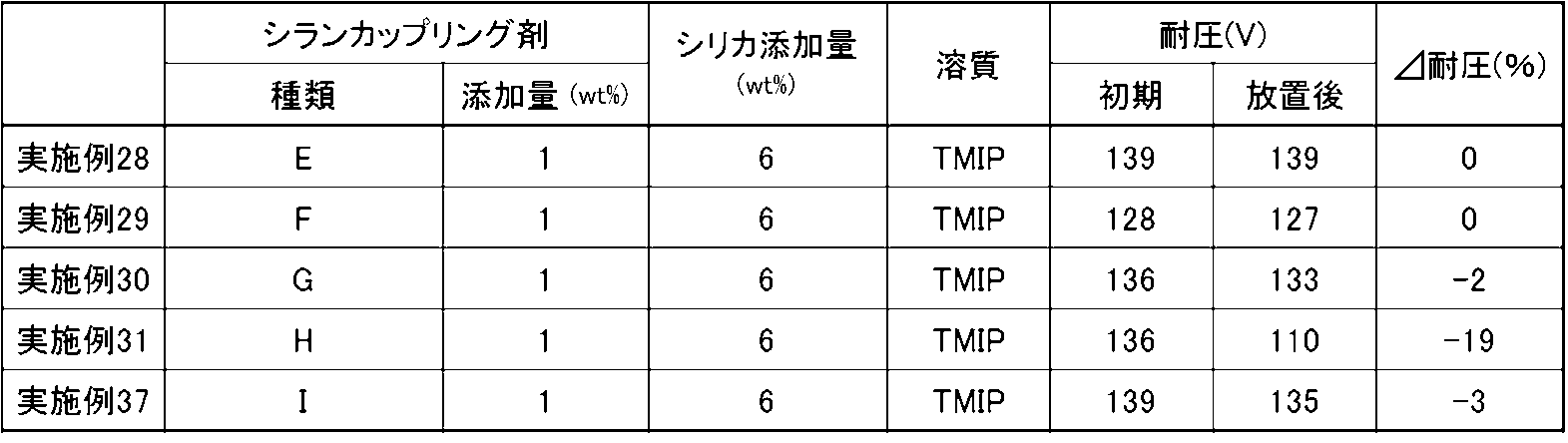
- the electrolytic capacitors of each example have improved withstand voltage at the initial stage and after standing as compared with Comparative Examples 1 and 4 in which silica and silane coupling agents were not added.
- Silica is adsorbed on the dielectric oxide film, and it is considered that silica becomes a resistance component, and it was confirmed that the withstand voltage after initial and after standing was improved according to this estimation mechanism.
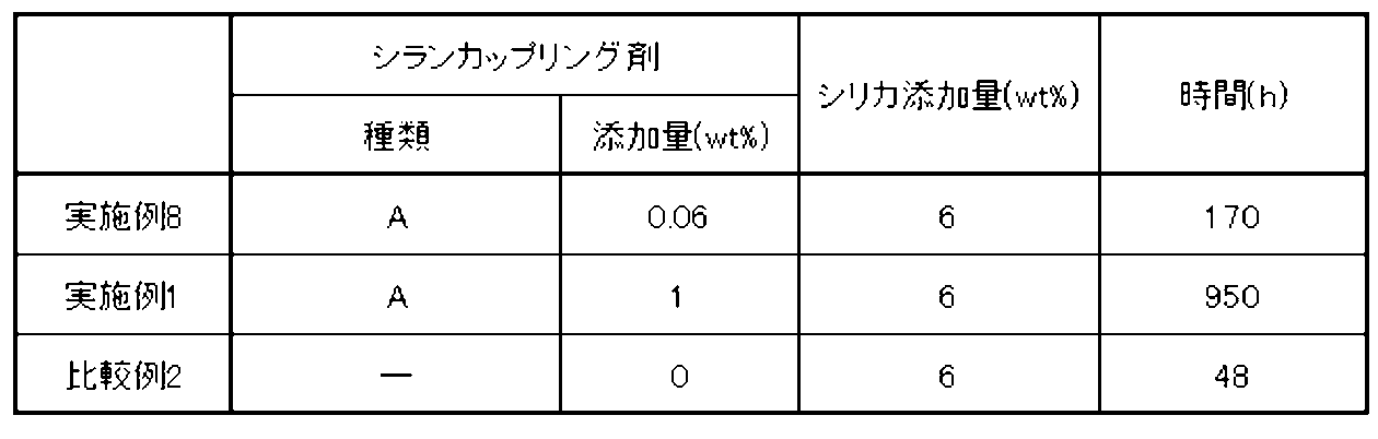
- the electrolytic capacitor of each example has a lower withstand voltage change rate than Comparative Example 2 in which only silica was added and no silane coupling agent was added. That is, when combined with the results shown in Table 1, it was confirmed that the gelation of the electrolyte due to the aggregation of silica was suppressed, thereby improving the withstand voltage and reducing the rate of change in the withstand voltage after standing.
- the initial withstand voltage was high in almost all of the examples.
- the silica of the example is not surface-modified in the initial stage, and since the number of hydroxyl groups is large, it is considered that the adsorptivity to the hydrophilic dielectric oxide film is high. It has been confirmed that the breakdown voltage is improved.
- Example 26 which mixed the silane coupling agent and the silica beforehand has a pressure
- Silane coupling agent A is 3-glycidoxypropylmethyldimethoxysilane
- B is 3-methacryloxypropyltriethoxysilane
- C is N-2- (aminoethyl) -3-aminopropylmethyldimethoxysilane
- D is 2- (3,4-Epooxycyclohexyl) ethyltrimethoxysilane.
- the silylating agent or silane coupling agent is 1, and the weight ratio was preferably 1.67 or less. More desirably, the addition amount of the silylating agent or the silane coupling agent is 5 wt% or less with respect to the total amount of the electrolytic solution, in other words, the silica is 1 and the weight ratio is 0.84 or less.
- an increase in equivalent series resistance or the like does not depend on the organic modifying group possessed by the silylating agent or the silane coupling agent.
- Silane coupling agent A is 3-glycidoxypropylmethyldimethoxysilane
- B is 3-methacryloxypropyltriethoxysilane
- C is N-2- (aminoethyl) -3-aminopropylmethyldimethoxysilane
- D is 2- (3,4-Epooxycyclohexyl) ethyltrimethoxysilane.
- Examples 1 to 3 are lower in capacitance after standing than Comparative Example 1 in which neither silica nor silane coupling agent was added to the electrolytic solution and Comparative Example 2 in which only silica was added to the electrolytic solution.
- ( ⁇ Cap) was small, increase in dielectric loss tangent after standing ( ⁇ tan ⁇ ) was small, and leakage current (LC) was also small.
- the effect of improving the pressure resistance is increased by adding a silane coupling agent and silica to the electrolytic solution.
- addition of a silylating agent or a silane coupling agent it was confirmed that the amount was desirably 10 wt% or less, more desirably 5 wt%, with respect to the total amount of the electrolytic solution.
- the addition amount of the silylating agent or the silane coupling agent of 5 wt% or less with respect to the total amount of the electrolytic solution is 0.84 or less in terms of the weight ratio with silica as 1.
Landscapes
- Engineering & Computer Science (AREA)
- Power Engineering (AREA)
- Chemical & Material Sciences (AREA)
- Chemical Kinetics & Catalysis (AREA)
- Electrochemistry (AREA)
- Microelectronics & Electronic Packaging (AREA)
- Compositions Of Macromolecular Compounds (AREA)
Abstract
Description

本発明の実施形態に係る電解コンデンサの実施例1として、定格電圧が50WV、定格容量が47μF、コンデンサ素子寸法が径6.3mm及び長さ8mmの巻回型の電解コンデンサを作製した。
実施例1の電解コンデンサと同一材料、同一方法及び同一条件にて実施例2の電解コンデンサを作製した。但し、電解液に添加する3-グリシドキシプロピルメチルジメトキシシランは、電解液の全量に対して3wt%とした。シリカに対する3-グリシドキシプロピルメチルジメトキシシランの添加量は、シリカを1として重量比で0.5となる。
実施例1の電解コンデンサと同一材料、同一方法及び同一条件にて実施例3の電解コンデンサを作製した。但し、電解液に添加する3-グリシドキシプロピルメチルジメトキシシランは、電解液の全量に対して5wt%とした。シリカに対する3-グリシドキシプロピルメチルジメトキシシランの添加量は、シリカを1として重量比で0.83となる。
実施例1の電解コンデンサと同一材料、同一方法及び同一条件にて実施例4の電解コンデンサを作製した。但し、電解液に添加する3-グリシドキシプロピルメチルジメトキシシランは、電解液の全量に対して10wt%とした。シリカに対する3-グリシドキシプロピルメチルジメトキシシランの添加量は、シリカを1として重量比で1.67となる。
実施例1の電解コンデンサと同一材料、同一方法及び同一条件にて実施例5の電解コンデンサを作製した。但し、電解液に添加する3-グリシドキシプロピルメチルジメトキシシランは、電解液の全量に対して20wt%とした。シリカに対する3-グリシドキシプロピルメチルジメトキシシランの添加量は、シリカを1として重量比で3.33となる。
実施例1の電解コンデンサと同一材料、同一方法及び同一条件にて実施例6の電解コンデンサを作製した。但し、電解液には、シランカップリング剤として3-メタクリロキシプロピルトリエトキシシラン(信越シリコーン製 KBE-503)を添加した。3-メタクリロキシプロピルトリエトキシシランは、電解液の全量に対して1wt%とした。シリカに対する3-メタクリロキシプロピルトリエトキシシランの添加量は、シリカを1として重量比で0.17となる。
実施例1の電解コンデンサと同一材料、同一方法及び同一条件にて実施例7の電解コンデンサを作製した。但し、電解液には、シランカップリング剤としてN-2-(アミノエチル)-3-アミノプロピルメチルジメトキシシラン(信越シリコーン製 KBM-602)を添加した。N-2-(アミノエチル)-3-アミノプロピルメチルジメトキシシランは、電解液の全量に対して1wt%とした。シリカに対するN-2-(アミノエチル)-3-アミノプロピルメチルジメトキシシランの添加量は、シリカを1として重量比で0.17となる。
実施例1の電解コンデンサと同一材料、同一方法及び同一条件にて実施例8の電解コンデンサを作製した。但し、電解液に添加する3-グリシドキシプロピルメチルジメトキシシランは、電解液の全量に対して0.06wt%とした。シリカに対する3-グリシドキシプロピルメチルジメトキシシランの添加量は、シリカを1として重量比で0.01となる。
実施例1の電解コンデンサと同一材料、同一方法及び同一条件にて実施例9の電解コンデンサを作製した。但し、電解液に添加する3-グリシドキシプロピルメチルジメトキシシランは、電解液の全量に対して0.5wt%とした。シリカに対する3-グリシドキシプロピルメチルジメトキシシランの添加量は、シリカを1として重量比で0.083となる。
実施例1の電解コンデンサと同一材料、同一方法及び同一条件にて実施例10の電解コンデンサを作製した。但し、電解液にはシランカップリング剤として、2-(3,4-エポシキシシクロヘキシル)エチルトリメトキシシラン(信越シリコーン製 KBM-303)を用い、電解液の全量に対して1wt%添加した。シリカに対する2-(3,4-エポシキシシクロヘキシル)エチルトリメトキシシランの添加量は、シリカを1として重量比で0.17となる。
実施例1の電解コンデンサと同一材料、同一方法及び同一条件にて実施例11の電解コンデンサを作製した。但し、電解液にはシランカップリング剤として、2-(3,4-エポシキシシクロヘキシル)エチルトリメトキシシランを用い、電解液の全量に対して3wt%添加した。シリカに対する2-(3,4-エポシキシシクロヘキシル)エチルトリメトキシシランの添加量は、シリカを1として重量比で0.5となる。
実施例1の電解コンデンサと同一材料、同一方法及び同一条件にて実施例12の電解コンデンサを作製した。但し、電解液にはシランカップリング剤として、2-(3,4-エポシキシシクロヘキシル)エチルトリメトキシシランを用い、電解液の全量に対して5wt%添加した。シリカに対する2-(3,4-エポシキシシクロヘキシル)エチルトリメトキシシランの添加量は、シリカを1として重量比で0.83となる。
実施例1の電解コンデンサと同一材料、同一方法及び同一条件にて実施例13の電解コンデンサを作製した。但し、電解液にはシランカップリング剤として、2-(3,4-エポシキシシクロヘキシル)エチルトリメトキシシランを用い、電解液の全量に対して10wt%添加した。シリカに対する2-(3,4-エポシキシシクロヘキシル)エチルトリメトキシシランの添加量は、シリカを1として重量比で1.67となる。
実施例1の電解コンデンサと同一材料、同一方法及び同一条件にて実施例14の電解コンデンサを作製した。但し、電解液にはシランカップリング剤として、2-(3,4-エポシキシシクロヘキシル)エチルトリメトキシシランを用い、電解液の全量に対して20wt%とした。シリカに対する2-(3,4-エポシキシシクロヘキシル)エチルトリメトキシシランの添加量は、シリカを1として重量比で3.33となる。
実施例1の電解コンデンサと同一材料、同一方法及び同一条件にて実施例15の電解コンデンサを作製した。但し、電解液に添加する3-グリシドキシプロピルメチルジメトキシシランは、電解液の全量に対して0.1wt%とした。シリカに対する3-グリシドキシプロピルメチルジメトキシシランの添加量は、シリカを1として重量比で0.017となる。
実施例1の電解コンデンサと同一材料、同一方法及び同一条件にて実施例16の電解コンデンサを作製した。但し、電解液に添加する3-グリシドキシプロピルメチルジメトキシシランは、電解液の全量に対して0.2wt%とした。シリカに対する3-グリシドキシプロピルメチルジメトキシシランの添加量は、シリカを1として重量比で0.033となる。
実施例1の電解コンデンサと同一材料、同一方法及び同一条件にて実施例17の電解コンデンサを作製した。但し、電解液に添加する3-グリシドキシプロピルメチルジメトキシシランは、電解液の全量に対して0.3wt%とした。シリカに対する3-グリシドキシプロピルメチルジメトキシシランの添加量は、シリカを1として重量比で0.05となる。
実施例1の電解コンデンサと同一材料、同一方法及び同一条件にて実施例18の電解コンデンサを作製した。但し、電解液に添加する3-グリシドキシプロピルメチルジメトキシシランは、電解液の全量に対して0.4wt%とした。シリカに対する3-グリシドキシプロピルメチルジメトキシシランの添加量は、シリカを1として重量比で0.067となる。
実施例1の電解コンデンサと同一材料、同一方法及び同一条件にて実施例19の電解コンデンサを作製した。但し、電解液にはシランカップリング剤として、3-メタクリロキシプロピルトリエトキシシランを用い、電解液の全量に対して0.06wt%添加した。シリカに対する3-メタクリロキシプロピルトリエトキシシランの添加量は、シリカを1として重量比で0.01となる。
実施例1の電解コンデンサと同一材料、同一方法及び同一条件にて実施例20の電解コンデンサを作製した。但し、電解液にはシランカップリング剤として、3-メタクリロキシプロピルトリエトキシシランを用い、電解液の全量に対して0.1wt%添加した。シリカに対する3-メタクリロキシプロピルトリエトキシシランの添加量は、シリカを1として重量比で0.017となる。
実施例1の電解コンデンサと同一材料、同一方法及び同一条件にて実施例21の電解コンデンサを作製した。但し、電解液にはシランカップリング剤として、3-メタクリロキシプロピルトリエトキシシランを用い、電解液の全量に対して0.3wt%添加した。シリカに対する3-メタクリロキシプロピルトリエトキシシランの添加量は、シリカを1として重量比で0.05となる。
実施例1の電解コンデンサと同一材料、同一方法及び同一条件にて実施例22の電解コンデンサを作製した。但し、電解液にはシランカップリング剤として、3-メタクリロキシプロピルトリエトキシシランを用い、電解液の全量に対して0.5wt%添加した。シリカに対する3-メタクリロキシプロピルトリエトキシシランの添加量は、シリカを1として重量比で0.083となる。
実施例1の電解コンデンサと同一材料、同一方法及び同一条件にて実施例23の電解コンデンサを作製した。但し、電解液にはシランカップリング剤として、3-メタクリロキシプロピルトリエトキシシランを用い、電解液の全量に対して2wt%添加した。シリカに対する3-メタクリロキシプロピルトリエトキシシランの添加量は、シリカを1として重量比で0.33となる。
実施例1の電解コンデンサと同一材料、同一方法及び同一条件にて実施例24の電解コンデンサを作製した。但し、電解液にはシランカップリング剤として、3-メタクリロキシプロピルトリエトキシシランを用い、電解液の全量に対して3wt%添加した。シリカに対する3-メタクリロキシプロピルトリエトキシシランの添加量は、シリカを1として重量比で0.5となる。
実施例1の電解コンデンサと同一材料、同一方法及び同一条件にて実施例25の電解コンデンサを作製した。但し、電解液には、シランカップリング剤として、2-(3,4-エポシキシシクロヘキシル)エチルトリメトキシシランを用い、溶質としてフタル酸1-エチル-2,3-ジメチルイミダゾリニウム(以下、EDMIPという)を用いた。2-(3,4-エポシキシシクロヘキシル)エチルトリメトキシシランは電解液の全量に対して3wt%、また、EDMIPは電解液の全量に対して20wt%添加した。シリカに対する3-メタクリロキシプロピルトリエトキシシランの添加量は、シリカを1として重量比で0.5となる。
実施例1の電解コンデンサと同一材料、同一方法及び同一条件にて実施例26の電解コンデンサを作製した。但し、予めシリカと3-グリシドキシプロピルメチルジメトキシシランとを混合したものを、γ‐ブチロラクトンとスルホランの混合溶媒に、TMIPおよびニトロ化合物と共に添加し、電解液を調製した。
実施例1の電解コンデンサと同一材料、同一方法及び同一条件にて実施例27の電解コンデンサを作製した。但し、電解液には、シランカップリング剤として、2-(3,4-エポシキシシクロヘキシル)エチルトリメトキシシランを用い、溶質としてフタル酸トリエチルアミン(以下、PhA/TEAという)を用いた。2-(3,4-エポシキシシクロヘキシル)エチルトリメトキシシランは電解液の全量に対して3wt%、また、PhA/TEAは電解液の全量に対して20wt%添加した。シリカに対する3-メタクリロキシプロピルトリエトキシシランの添加量は、シリカを1として重量比で0.5となる。
実施例1の電解コンデンサと同一材料、同一方法及び同一条件にて実施例28の電解コンデンサを作製した。但し、電解液には、シランカップリング剤としてビニルトリメトキシシラン(信越シリコーン製 KBM-1003)を添加した。ビニルトリメトキシシランは、電解液の全量に対して1wt%とした。シリカに対するビニルトリメトキシシランの添加量は、シリカを1として重量比で0.17となる。
実施例1の電解コンデンサと同一材料、同一方法及び同一条件にて実施例29の電解コンデンサを作製した。但し、電解液には、シランカップリング剤としてp-スチリルトリメトキシシラン(信越シリコーン製 KBM-1403)を添加した。p-スチリルトリメトキシシランは、電解液の全量に対して1wt%とした。シリカに対するp-スチリルトリメトキシシランの添加量は、シリカを1として重量比で0.17となる。
実施例1の電解コンデンサと同一材料、同一方法及び同一条件にて実施例30の電解コンデンサを作製した。但し、電解液には、シランカップリング剤として3-アクリロキシプロピルトリメトキシシラン(信越シリコーン製 KBM-5103)を添加した。3-アクリロキシプロピルトリメトキシシランは、電解液の全量に対して1wt%とした。シリカに対する3-アクリロキシプロピルトリメトキシシランの添加量は、シリカを1として重量比で0.17となる。
実施例1の電解コンデンサと同一材料、同一方法及び同一条件にて実施例31の電解コンデンサを作製した。但し、電解液には、シランカップリング剤として3-イソシアネートプロピルトリエトキシシラン(信越シリコーン製 KBE-9007)を添加した。3-イソシアネートプロピルトリエトキシシランは、電解液の全量に対して1wt%とした。シリカに対する3-イソシアネートプロピルトリエトキシシランの添加量は、シリカを1として重量比で0.17となる。
実施例1の電解コンデンサと同一材料、同一方法及び同一条件にて実施例32の電解コンデンサを作製した。但し、電解液中、シリカは1wt%とした。また、シランカップリング剤として、2-(3,4-エポシキシシクロヘキシル)エチルトリメトキシシランを用いた。2-(3,4-エポシキシシクロヘキシル)エチルトリメトキシシランは、電解液の全量に対して0.33wt%添加した。シリカに対する2-(3,4-エポシキシシクロヘキシル)エチルトリメトキシシランの添加量は、シリカを1として重量比で0.33となる。
実施例32の電解コンデンサと同一材料、同一方法及び同一条件にて実施例33の電解コンデンサを作製した。但し、電解液中、シリカは2wt%とした。また、2-(3,4-エポシキシシクロヘキシル)エチルトリメトキシシランは、電解液の全量に対して0.66wt%添加した。シリカに対する2-(3,4-エポシキシシクロヘキシル)エチルトリメトキシシランの添加量は、実施例32と同じく、シリカを1として重量比で0.33となる。
実施例32の電解コンデンサと同一材料、同一方法及び同一条件にて実施例34の電解コンデンサを作製した。但し、電解液中、シリカは6wt%とした。また、2-(3,4-エポシキシシクロヘキシル)エチルトリメトキシシランは、電解液の全量に対して2wt%添加した。シリカに対する2-(3,4-エポシキシシクロヘキシル)エチルトリメトキシシランの添加量は、実施例32と同じく、シリカを1として重量比で0.33となる。
実施例32の電解コンデンサと同一材料、同一方法及び同一条件にて実施例35の電解コンデンサを作製した。但し、電解液中、シリカは9wt%とした。また、2-(3,4-エポシキシシクロヘキシル)エチルトリメトキシシランは、電解液の全量に対して3wt%添加した。シリカに対する2-(3,4-エポシキシシクロヘキシル)エチルトリメトキシシランの添加量は、実施例32と同じく、シリカを1として重量比で0.33となる。
実施例32の電解コンデンサと同一材料、同一方法及び同一条件にて実施例36の電解コンデンサを作製した。但し、電解液中、シリカは15wt%とした。また、2-(3,4-エポシキシシクロヘキシル)エチルトリメトキシシランは、電解液の全量に対して4wt%添加した。シリカに対する2-(3,4-エポシキシシクロヘキシル)エチルトリメトキシシランの添加量は、実施例32と同じく、シリカを1として重量比で0.33となる。
実施例1の電解コンデンサと同一材料、同一方法及び同一条件にて実施例37の電解コンデンサを作製した。但し、電解液には、シランカップリング剤として3-グリシドキシプロピルメチルジエトキシシラン(信越シリコーン製 KBE-402)を添加した。3-グリシドキシプロピルメチルジエトキシシランは、電解液の全量に対して1wt%とした。シリカに対する3-グリシドキシプロピルメチルジエトキシシランの添加量は、シリカを1として重量比で0.17となる。
実施例1の電解コンデンサと同一材料、同一方法及び同一条件にて比較例1の電解コンデンサを作製した。但し、電解液にはシリカもシランカップリング剤も添加しなかった。
実施例1の電解コンデンサと同一材料、同一方法及び同一条件にて比較例2の電解コンデンサを作製した。但し、電解液にはシランカップリング剤を添加しなかった。
実施例1の電解コンデンサと同一材料、同一方法及び同一条件にて比較例3の電解コンデンサを作製した。但し、予めシリカと3-グリシドキシプロピルメチルジメトキシシランとを混合し、加熱(125℃、45分間)したものを、溶質およびニトロ化合物とともに、γ-ブチロラクトンとスルホランとの混合溶媒に添加し、電解液とした。
実施例1の電解コンデンサと同一材料、同一方法及び同一条件にて比較例4の電解コンデンサを作製した。但し、電解液にはシリカを添加しなかった。
実施例32の電解コンデンサと同一材料、同一方法及び同一条件にて比較例5の電解コンデンサを作製した。但し、電解液にはシランカップリング剤を添加せず、シリカの添加量を電解液全量に対して2wt%とした。
実施例32の電解コンデンサと同一材料、同一方法及び同一条件にて比較例6の電解コンデンサを作製した。但し、電解液にはシランカップリング剤を添加せず、シリカの添加量を電解液全量に対して9wt%とした。
実施例32の電解コンデンサと同一材料、同一方法及び同一条件にて比較例7の電解コンデンサを作製した。但し、電解液にはシランカップリング剤を添加せず、シリカの添加量を電解液全量に対して15wt%とした。
実施例1及び8並びに比較例2の電解コンデンサの電解液を用い、各電解液がゲル化するまでの時間を計測した。各電解液をアンプル管に入れ、150℃で保持し、各測定時間においてゲル化しているか目視にて確認した。電解液を収容したアンプル管を傾けても内容物に流動性がない状態をゲル化とした。その結果を表1に示す。表1に記載の時間は、ゲル化したことを確認した時間を記載しており、ゲル化した時間ではない。また、表1中、シランカップリング剤Aは3-グリシドキシプロピルメチルジメトキシシランを示す。
次に、シリカの添加量が6wt%である各実施例及び比較例の電解コンデンサの耐圧特性を評価した(実施例32~36及び比較例5~7を除く)。評価のために、各実施例および比較例の初期耐圧と125℃、100時間無負荷放置後の耐圧を測定し、また耐圧変化率(Δ耐圧)を算出した。尚、耐圧変化率を検証するために、外装ケースの加締め後にエージング処理を行っていない電解コンデンサを用いた。その結果を表2及び表3に示す。ここで、シランカップリング剤Aは3-グリシドキシプロピルメチルジメトキシシラン、Bは3-メタクリロキシプロピルトリエトキシシラン、CはN-2-(アミノエチル)-3-アミノプロピルメチルジメトキシシラン、Dは2-(3,4-エポシキシシクロヘキシル)エチルトリメトキシシラン、Eはビニルトリメトキシシラン、Fはp-スチリルトリメトキシシラン、Gは3-アクリロキシプロピルトリメトキシシラン、Hは3-イソシアネートプロピルトリエトキシシラン、Iは3-グリシドキシプロピルメチルジエトキシシランである。

シリカの添加量を変化させた実施例32~36及び比較例2及び5~7の電解コンデンサの耐圧特性を評価した。評価のために、各実施例および比較例の初期耐圧と125℃、100時間無負荷放置後の耐圧を測定し、また耐圧変化率(Δ耐圧)を算出した。尚、耐圧変化率を検証するために、外装ケースの加締め後にエージング処理を行っていない電解コンデンサを用いた。その結果を表4に示す。

実施例1~7及び10~14、並びに比較例1、2及び4の電解コンデンサの初期特性を評価した。電解コンデンサの初期特性として、静電容量(Cap)、等価直列抵抗(ESR)及び誘電正接(tanδ)を測定した。その結果を表5に示す。シランカップリング剤Aは3-グリシドキシプロピルメチルジメトキシシラン、Bは3-メタクリロキシプロピルトリエトキシシラン、CはN-2-(アミノエチル)-3-アミノプロピルメチルジメトキシシラン、Dは2-(3,4-エポシキシシクロヘキシル)エチルトリメトキシシランである。

実施例1~5及び10~14、並びに比較例1、2及び4の電解コンデンサの無負荷放置試験を行った。試験の評価のために、実施例1~5及び比較例1及び2の初期と155℃、270時間無負荷放置後との間の静電容量変化率(ΔCap)、等価直列抵抗変化率(ΔESR)、誘電正接変化率(Δtanδ)を算出し、また無負荷放置試験後の漏れ電流(LC)を測定した。その結果を表6に示す。シランカップリング剤Aは3-グリシドキシプロピルメチルジメトキシシラン、Bは3-メタクリロキシプロピルトリエトキシシラン、CはN-2-(アミノエチル)-3-アミノプロピルメチルジメトキシシラン、Dは2-(3,4-エポシキシシクロヘキシル)エチルトリメトキシシランである。

Claims (13)
- 溶媒、溶質、シリカ及び下記一般式(化1)で表されるシリル化剤又はシランカップリング剤とを含むこと、
を特徴とする電解コンデンサ用電解液。

- 前記一般式(化1)で表されるシリル化剤又はシランカップリング剤は、3-グリシドキシプロピルメチルジメトキシシラン、3-メタクリロキシプロピルトリエトキシシラン、2-(3,4-エポシキシシクロヘキシル)エチルトリメトキシシラン、N-2-(アミノエチル)-3-アミノプロピルメチルジメトキシシラン、ビニルトリメトキシシラン、p-スチリルトリメトキシシラン、3-アクリロキシプロピルトリメトキシシラン、3-イソシアネートプロピルトリエトキシシラン及び3-グリシドキシプロピルメチルジエトキシシランの群から選ばれる1種以上であること、
を特徴とする請求項1記載の電解コンデンサ用電解液。 - 前記シリカに対する前記シリル化剤又はシランカップリング剤の添加量は、重量比で1:0.01以上~3.33以下であること、
を特徴とする請求項1又は2記載の電解コンデンサ用電解液。 - 前記シリカに対する前記シリル化剤又はシランカップリング剤の添加量は、
重量比で1:0.03以上であること、
を特徴とする請求項1又は2記載の電解コンデンサ用電解液。 - 前記シリカの添加量は、当該電解コンデンサ用電解液全体に対して2wt%以上35wt%以下であること、
を特徴とする請求項1乃至4の何れかに記載の電解コンデンサ用電解液。 - 請求項1乃至5の何れかに記載の電解コンデンサ用電解液を備えること、
を特徴とする電解コンデンサ。 - 一対の電極箔を備え、
前記シリル化剤又は前記シランカップリング剤は、シリカ及び/又は前記電極箔の表面に結合し、
前記電極箔の表面に前記シリカが存在していること、
を特徴とする請求項6記載の電解コンデンサ。 - 前記シリル化剤又は前記シランカップリング剤で表面修飾された前記シリカが水酸基で前記電極箔の表面に吸着していること、
を特徴とする請求項7記載の電解コンデンサ。 - 前記シリル化剤又は前記シランカップリング剤は、シリカ及び前記電極箔の表面に結合し、
前記シリル化剤又は前記シランカップリング剤を介して、前記電極箔の表面に前記シリカが近接していること、
を特徴とする請求項8記載の電解コンデンサ。 - 誘電体酸化皮膜が形成された陽極箔と陰極箔をセパレータを介して対向させてコンデンサ素子を形成し、
前記コンデンサ素子に、少なくとも溶媒、溶質、シリカ及び下記一般式(化2)で表されるシリル化剤又はシランカップリング剤を含浸させること、
を特徴とする電解コンデンサの製造方法。
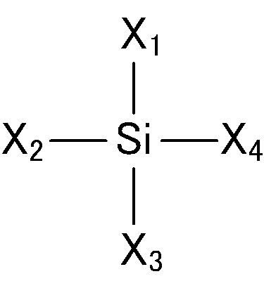
- 前記一般式(化2)で表されるシリル化剤又はシランカップリング剤は、3-グリシドキシプロピルメチルジメトキシシラン、3-メタクリロキシプロピルトリエトキシシラン、2-(3,4-エポシキシシクロヘキシル)エチルトリメトキシシラン、N-2-(アミノエチル)-3-アミノプロピルメチルジメトキシシラン、ビニルトリメトキシシラン、p-スチリルトリメトキシシラン、3-アクリロキシプロピルトリメトキシシラン、3-イソシアネートプロピルトリエトキシシラン及び3-グリシドキシプロピルメチルジエトキシシランの群から選ばれる1種以上であること、
を特徴とする請求項10記載の電解コンデンサの製造方法。 - 前記コンデンサ素子への前記電解液の含浸工程以降に、前記電解液中の前記シリカを前記電解液中の前記シリル化剤又は前記シランカップリング剤で表面修飾すること、
を特徴とする請求項10又は11記載の電解コンデンサの製造方法。 - 前記コンデンサ素子への前記電解液の含浸工程以降に、熱処理すること、
を特徴とする請求項12記載の電解コンデンサの製造方法。
Priority Applications (3)
| Application Number | Priority Date | Filing Date | Title |
|---|---|---|---|
| CN201880008035.6A CN110199367B (zh) | 2017-01-26 | 2018-01-26 | 电解电容器用电解液、电解电容器以及电解电容器的制造方法 |
| JP2018564647A JP7200677B2 (ja) | 2017-01-26 | 2018-01-26 | 電解コンデンサ用電解液、電解コンデンサ、及び電解コンデンサの製造方法 |
| KR1020197021558A KR102423622B1 (ko) | 2017-01-26 | 2018-01-26 | 전해 콘덴서용 전해액, 전해 콘덴서 및 전해 콘덴서의 제조 방법 |
Applications Claiming Priority (2)
| Application Number | Priority Date | Filing Date | Title |
|---|---|---|---|
| JP2017-012163 | 2017-01-26 | ||
| JP2017012163 | 2017-01-26 |
Publications (1)
| Publication Number | Publication Date |
|---|---|
| WO2018139573A1 true WO2018139573A1 (ja) | 2018-08-02 |
Family
ID=62978935
Family Applications (1)
| Application Number | Title | Priority Date | Filing Date |
|---|---|---|---|
| PCT/JP2018/002418 Ceased WO2018139573A1 (ja) | 2017-01-26 | 2018-01-26 | 電解コンデンサ用電解液、電解コンデンサ、及び電解コンデンサの製造方法 |
Country Status (5)
| Country | Link |
|---|---|
| JP (1) | JP7200677B2 (ja) |
| KR (1) | KR102423622B1 (ja) |
| CN (1) | CN110199367B (ja) |
| TW (1) | TWI762559B (ja) |
| WO (1) | WO2018139573A1 (ja) |
Cited By (4)
| Publication number | Priority date | Publication date | Assignee | Title |
|---|---|---|---|---|
| WO2020111093A1 (ja) * | 2018-11-30 | 2020-06-04 | パナソニックIpマネジメント株式会社 | 電解コンデンサおよびその製造方法 |
| WO2020116582A1 (ja) * | 2018-12-05 | 2020-06-11 | 日立化成株式会社 | 電解液及び電気化学デバイス |
| JP2021163847A (ja) * | 2020-03-31 | 2021-10-11 | 三菱ケミカル株式会社 | 変性シリカ、及びこれを含む電解コンデンサ用電解液 |
| CN114783777A (zh) * | 2022-05-17 | 2022-07-22 | 富之庆电子(深圳)有限公司 | 一种高压用铝电解电容器及电解液 |
Families Citing this family (1)
| Publication number | Priority date | Publication date | Assignee | Title |
|---|---|---|---|---|
| TWI810503B (zh) * | 2019-12-18 | 2023-08-01 | 日商日本貴彌功股份有限公司 | 電解電容器 |
Citations (3)
| Publication number | Priority date | Publication date | Assignee | Title |
|---|---|---|---|---|
| JPH06196368A (ja) * | 1992-12-24 | 1994-07-15 | Mitsubishi Petrochem Co Ltd | 電解コンデンサ用電解液 |
| JPH10241999A (ja) * | 1997-03-03 | 1998-09-11 | Nippon Chemicon Corp | 電解コンデンサ用電解液 |
| JP2016171110A (ja) * | 2015-03-11 | 2016-09-23 | Necトーキン株式会社 | 電解コンデンサ用電解液、電解コンデンサ |
-
2018
- 2018-01-26 KR KR1020197021558A patent/KR102423622B1/ko active Active
- 2018-01-26 JP JP2018564647A patent/JP7200677B2/ja active Active
- 2018-01-26 CN CN201880008035.6A patent/CN110199367B/zh active Active
- 2018-01-26 TW TW107102502A patent/TWI762559B/zh active
- 2018-01-26 WO PCT/JP2018/002418 patent/WO2018139573A1/ja not_active Ceased
Patent Citations (3)
| Publication number | Priority date | Publication date | Assignee | Title |
|---|---|---|---|---|
| JPH06196368A (ja) * | 1992-12-24 | 1994-07-15 | Mitsubishi Petrochem Co Ltd | 電解コンデンサ用電解液 |
| JPH10241999A (ja) * | 1997-03-03 | 1998-09-11 | Nippon Chemicon Corp | 電解コンデンサ用電解液 |
| JP2016171110A (ja) * | 2015-03-11 | 2016-09-23 | Necトーキン株式会社 | 電解コンデンサ用電解液、電解コンデンサ |
Cited By (8)
| Publication number | Priority date | Publication date | Assignee | Title |
|---|---|---|---|---|
| WO2020111093A1 (ja) * | 2018-11-30 | 2020-06-04 | パナソニックIpマネジメント株式会社 | 電解コンデンサおよびその製造方法 |
| WO2020116582A1 (ja) * | 2018-12-05 | 2020-06-11 | 日立化成株式会社 | 電解液及び電気化学デバイス |
| CN113396500A (zh) * | 2018-12-05 | 2021-09-14 | 昭和电工材料株式会社 | 电解液及电化学器件 |
| JPWO2020116582A1 (ja) * | 2018-12-05 | 2021-10-21 | 昭和電工マテリアルズ株式会社 | 電解液及び電気化学デバイス |
| JP7415947B2 (ja) | 2018-12-05 | 2024-01-17 | 株式会社レゾナック | 電解液及び電気化学デバイス |
| JP2021163847A (ja) * | 2020-03-31 | 2021-10-11 | 三菱ケミカル株式会社 | 変性シリカ、及びこれを含む電解コンデンサ用電解液 |
| JP7547757B2 (ja) | 2020-03-31 | 2024-09-10 | 三菱ケミカル株式会社 | 変性シリカ、及びこれを含む電解コンデンサ用電解液 |
| CN114783777A (zh) * | 2022-05-17 | 2022-07-22 | 富之庆电子(深圳)有限公司 | 一种高压用铝电解电容器及电解液 |
Also Published As
| Publication number | Publication date |
|---|---|
| TW201840540A (zh) | 2018-11-16 |
| KR102423622B1 (ko) | 2022-07-20 |
| KR20190105017A (ko) | 2019-09-11 |
| JPWO2018139573A1 (ja) | 2019-11-14 |
| CN110199367A (zh) | 2019-09-03 |
| TWI762559B (zh) | 2022-05-01 |
| JP7200677B2 (ja) | 2023-01-10 |
| CN110199367B (zh) | 2021-11-26 |
Similar Documents
| Publication | Publication Date | Title |
|---|---|---|
| JP7200677B2 (ja) | 電解コンデンサ用電解液、電解コンデンサ、及び電解コンデンサの製造方法 | |
| JP7384161B2 (ja) | 電解コンデンサ用電解液及び電解コンデンサ | |
| WO2020059609A1 (ja) | 電極体、電極体を備える電解コンデンサ、及び電極体の製造方法 | |
| TWI399771B (zh) | 電解電容器 | |
| JP3669804B2 (ja) | 電解コンデンサ用電解液 | |
| JP6260925B2 (ja) | 電解コンデンサ用電解液及び電解コンデンサ | |
| JP7375540B2 (ja) | 固体電解コンデンサ | |
| JP4128465B2 (ja) | 電解コンデンサ用電解液 | |
| CN104704584B (zh) | 电解电容器用电解液及电解电容器 | |
| JP4707538B2 (ja) | 電解コンデンサの駆動用電解液及びそれを用いた電解コンデンサ | |
| JP3176611B2 (ja) | 電解コンデンサ用電解液 | |
| JP2006165001A (ja) | アルミニウム電解コンデンサ | |
| JP4449305B2 (ja) | アルミ電解コンデンサ | |
| JP4724336B2 (ja) | 電解コンデンサの駆動用電解液 | |
| JP2023097332A (ja) | 電解コンデンサ用電解液及び電解コンデンサ | |
| JP2026009801A (ja) | 電解コンデンサ用電解液、電解コンデンサ及び電解コンデンサの製造方法 | |
| JP2025125536A (ja) | 電解コンデンサ及び製造方法 | |
| JP4576070B2 (ja) | 電解コンデンサの駆動用電解液 | |
| JP2021163864A (ja) | 電解コンデンサ及び電力変換器 | |
| WO2025205661A1 (ja) | 電解コンデンサ及び製造方法 | |
| JP2025059293A (ja) | 電解コンデンサ及び製造方法 | |
| JP2008091371A (ja) | 電解コンデンサおよびその製造方法 | |
| JP2007184303A (ja) | 電解コンデンサの駆動用電解液、および電解コンデンサ | |
| JP2008085241A (ja) | 電解コンデンサ | |
| JP2007273927A (ja) | 電解コンデンサ |
Legal Events
| Date | Code | Title | Description |
|---|---|---|---|
| 121 | Ep: the epo has been informed by wipo that ep was designated in this application |
Ref document number: 18744846 Country of ref document: EP Kind code of ref document: A1 |
|
| ENP | Entry into the national phase |
Ref document number: 2018564647 Country of ref document: JP Kind code of ref document: A |
|
| ENP | Entry into the national phase |
Ref document number: 20197021558 Country of ref document: KR Kind code of ref document: A |
|
| NENP | Non-entry into the national phase |
Ref country code: DE |
|
| 122 | Ep: pct application non-entry in european phase |
Ref document number: 18744846 Country of ref document: EP Kind code of ref document: A1 |