WO2018123288A1 - 表示装置 - Google Patents
表示装置 Download PDFInfo
- Publication number
- WO2018123288A1 WO2018123288A1 PCT/JP2017/040402 JP2017040402W WO2018123288A1 WO 2018123288 A1 WO2018123288 A1 WO 2018123288A1 JP 2017040402 W JP2017040402 W JP 2017040402W WO 2018123288 A1 WO2018123288 A1 WO 2018123288A1
- Authority
- WO
- WIPO (PCT)
- Prior art keywords
- main body
- display device
- display panel
- stand
- attached
- Prior art date
Links
- 238000009434 installation Methods 0.000 claims abstract description 29
- 238000004891 communication Methods 0.000 claims description 16
- 230000000087 stabilizing effect Effects 0.000 claims description 2
- 239000011347 resin Substances 0.000 description 7
- 229920005989 resin Polymers 0.000 description 7
- 230000000694 effects Effects 0.000 description 5
- 229910052782 aluminium Inorganic materials 0.000 description 4
- XAGFODPZIPBFFR-UHFFFAOYSA-N aluminium Chemical compound [Al] XAGFODPZIPBFFR-UHFFFAOYSA-N 0.000 description 4
- 238000010586 diagram Methods 0.000 description 4
- 230000006641 stabilisation Effects 0.000 description 4
- 238000011105 stabilization Methods 0.000 description 4
- 239000011521 glass Substances 0.000 description 3
- 230000000052 comparative effect Effects 0.000 description 2
- 239000000463 material Substances 0.000 description 2
- 229910052751 metal Inorganic materials 0.000 description 2
- 239000002184 metal Substances 0.000 description 2
- 238000012986 modification Methods 0.000 description 2
- 230000004048 modification Effects 0.000 description 2
- 238000012545 processing Methods 0.000 description 2
- 230000003014 reinforcing effect Effects 0.000 description 2
- 238000013461 design Methods 0.000 description 1
- 238000009792 diffusion process Methods 0.000 description 1
- 238000005516 engineering process Methods 0.000 description 1
- 238000007667 floating Methods 0.000 description 1
- 230000017525 heat dissipation Effects 0.000 description 1
- 238000000034 method Methods 0.000 description 1
- 230000001151 other effect Effects 0.000 description 1
- 230000002093 peripheral effect Effects 0.000 description 1
Images


Classifications
-
- G—PHYSICS
- G06—COMPUTING; CALCULATING OR COUNTING
- G06F—ELECTRIC DIGITAL DATA PROCESSING
- G06F1/00—Details not covered by groups G06F3/00 - G06F13/00 and G06F21/00
- G06F1/16—Constructional details or arrangements
- G06F1/1601—Constructional details related to the housing of computer displays, e.g. of CRT monitors, of flat displays
- G06F1/1605—Multimedia displays, e.g. with integrated or attached speakers, cameras, microphones
-
- F—MECHANICAL ENGINEERING; LIGHTING; HEATING; WEAPONS; BLASTING
- F16—ENGINEERING ELEMENTS AND UNITS; GENERAL MEASURES FOR PRODUCING AND MAINTAINING EFFECTIVE FUNCTIONING OF MACHINES OR INSTALLATIONS; THERMAL INSULATION IN GENERAL
- F16M—FRAMES, CASINGS OR BEDS OF ENGINES, MACHINES OR APPARATUS, NOT SPECIFIC TO ENGINES, MACHINES OR APPARATUS PROVIDED FOR ELSEWHERE; STANDS; SUPPORTS
- F16M11/00—Stands or trestles as supports for apparatus or articles placed thereon ; Stands for scientific apparatus such as gravitational force meters
- F16M11/02—Heads
- F16M11/04—Means for attachment of apparatus; Means allowing adjustment of the apparatus relatively to the stand
- F16M11/06—Means for attachment of apparatus; Means allowing adjustment of the apparatus relatively to the stand allowing pivoting
- F16M11/10—Means for attachment of apparatus; Means allowing adjustment of the apparatus relatively to the stand allowing pivoting around a horizontal axis
-
- F—MECHANICAL ENGINEERING; LIGHTING; HEATING; WEAPONS; BLASTING
- F16—ENGINEERING ELEMENTS AND UNITS; GENERAL MEASURES FOR PRODUCING AND MAINTAINING EFFECTIVE FUNCTIONING OF MACHINES OR INSTALLATIONS; THERMAL INSULATION IN GENERAL
- F16M—FRAMES, CASINGS OR BEDS OF ENGINES, MACHINES OR APPARATUS, NOT SPECIFIC TO ENGINES, MACHINES OR APPARATUS PROVIDED FOR ELSEWHERE; STANDS; SUPPORTS
- F16M11/00—Stands or trestles as supports for apparatus or articles placed thereon ; Stands for scientific apparatus such as gravitational force meters
- F16M11/20—Undercarriages with or without wheels
- F16M11/22—Undercarriages with or without wheels with approximately constant height, e.g. with constant length of column or of legs
-
- G—PHYSICS
- G06—COMPUTING; CALCULATING OR COUNTING
- G06F—ELECTRIC DIGITAL DATA PROCESSING
- G06F1/00—Details not covered by groups G06F3/00 - G06F13/00 and G06F21/00
- G06F1/16—Constructional details or arrangements
- G06F1/1613—Constructional details or arrangements for portable computers
- G06F1/1633—Constructional details or arrangements of portable computers not specific to the type of enclosures covered by groups G06F1/1615 - G06F1/1626
- G06F1/1656—Details related to functional adaptations of the enclosure, e.g. to provide protection against EMI, shock, water, or to host detachable peripherals like a mouse or removable expansions units like PCMCIA cards, or to provide access to internal components for maintenance or to removable storage supports like CDs or DVDs, or to mechanically mount accessories
- G06F1/1658—Details related to functional adaptations of the enclosure, e.g. to provide protection against EMI, shock, water, or to host detachable peripherals like a mouse or removable expansions units like PCMCIA cards, or to provide access to internal components for maintenance or to removable storage supports like CDs or DVDs, or to mechanically mount accessories related to the mounting of internal components, e.g. disc drive or any other functional module
-
- G—PHYSICS
- G06—COMPUTING; CALCULATING OR COUNTING
- G06F—ELECTRIC DIGITAL DATA PROCESSING
- G06F1/00—Details not covered by groups G06F3/00 - G06F13/00 and G06F21/00
- G06F1/16—Constructional details or arrangements
- G06F1/1613—Constructional details or arrangements for portable computers
- G06F1/1633—Constructional details or arrangements of portable computers not specific to the type of enclosures covered by groups G06F1/1615 - G06F1/1626
- G06F1/1684—Constructional details or arrangements related to integrated I/O peripherals not covered by groups G06F1/1635 - G06F1/1675
- G06F1/1688—Constructional details or arrangements related to integrated I/O peripherals not covered by groups G06F1/1635 - G06F1/1675 the I/O peripheral being integrated loudspeakers
-
- G—PHYSICS
- G06—COMPUTING; CALCULATING OR COUNTING
- G06F—ELECTRIC DIGITAL DATA PROCESSING
- G06F1/00—Details not covered by groups G06F3/00 - G06F13/00 and G06F21/00
- G06F1/16—Constructional details or arrangements
- G06F1/1613—Constructional details or arrangements for portable computers
- G06F1/1633—Constructional details or arrangements of portable computers not specific to the type of enclosures covered by groups G06F1/1615 - G06F1/1626
- G06F1/1684—Constructional details or arrangements related to integrated I/O peripherals not covered by groups G06F1/1635 - G06F1/1675
- G06F1/1698—Constructional details or arrangements related to integrated I/O peripherals not covered by groups G06F1/1635 - G06F1/1675 the I/O peripheral being a sending/receiving arrangement to establish a cordless communication link, e.g. radio or infrared link, integrated cellular phone
-
- G—PHYSICS
- G09—EDUCATION; CRYPTOGRAPHY; DISPLAY; ADVERTISING; SEALS
- G09F—DISPLAYING; ADVERTISING; SIGNS; LABELS OR NAME-PLATES; SEALS
- G09F9/00—Indicating arrangements for variable information in which the information is built-up on a support by selection or combination of individual elements
-
- H—ELECTRICITY
- H04—ELECTRIC COMMUNICATION TECHNIQUE
- H04N—PICTORIAL COMMUNICATION, e.g. TELEVISION
- H04N5/00—Details of television systems
- H04N5/64—Constructional details of receivers, e.g. cabinets or dust covers
- H04N5/655—Construction or mounting of chassis, e.g. for varying the elevation of the tube
-
- H—ELECTRICITY
- H04—ELECTRIC COMMUNICATION TECHNIQUE
- H04R—LOUDSPEAKERS, MICROPHONES, GRAMOPHONE PICK-UPS OR LIKE ACOUSTIC ELECTROMECHANICAL TRANSDUCERS; DEAF-AID SETS; PUBLIC ADDRESS SYSTEMS
- H04R7/00—Diaphragms for electromechanical transducers; Cones
- H04R7/02—Diaphragms for electromechanical transducers; Cones characterised by the construction
- H04R7/04—Plane diaphragms
- H04R7/045—Plane diaphragms using the distributed mode principle, i.e. whereby the acoustic radiation is emanated from uniformly distributed free bending wave vibration induced in a stiff panel and not from pistonic motion
-
- F—MECHANICAL ENGINEERING; LIGHTING; HEATING; WEAPONS; BLASTING
- F16—ENGINEERING ELEMENTS AND UNITS; GENERAL MEASURES FOR PRODUCING AND MAINTAINING EFFECTIVE FUNCTIONING OF MACHINES OR INSTALLATIONS; THERMAL INSULATION IN GENERAL
- F16M—FRAMES, CASINGS OR BEDS OF ENGINES, MACHINES OR APPARATUS, NOT SPECIFIC TO ENGINES, MACHINES OR APPARATUS PROVIDED FOR ELSEWHERE; STANDS; SUPPORTS
- F16M2200/00—Details of stands or supports
- F16M2200/08—Foot or support base
-
- G—PHYSICS
- G06—COMPUTING; CALCULATING OR COUNTING
- G06F—ELECTRIC DIGITAL DATA PROCESSING
- G06F2200/00—Indexing scheme relating to G06F1/04 - G06F1/32
- G06F2200/16—Indexing scheme relating to G06F1/16 - G06F1/18
- G06F2200/163—Indexing scheme relating to constructional details of the computer
- G06F2200/1631—Panel PC, e.g. single housing hosting PC and display panel
-
- H—ELECTRICITY
- H04—ELECTRIC COMMUNICATION TECHNIQUE
- H04R—LOUDSPEAKERS, MICROPHONES, GRAMOPHONE PICK-UPS OR LIKE ACOUSTIC ELECTROMECHANICAL TRANSDUCERS; DEAF-AID SETS; PUBLIC ADDRESS SYSTEMS
- H04R7/00—Diaphragms for electromechanical transducers; Cones
- H04R7/02—Diaphragms for electromechanical transducers; Cones characterised by the construction
- H04R7/04—Plane diaphragms
- H04R7/06—Plane diaphragms comprising a plurality of sections or layers
- H04R7/08—Plane diaphragms comprising a plurality of sections or layers comprising superposed layers separated by air or other fluid
Definitions
- This disclosure relates to a display device.
- a speaker is often arranged at the bottom of the main body including the display unit.
- a stand is attached to the lower part of the main body.
- the installation space makes it possible to effectively emit the sound from the speakers to the front side.
- a display device includes a main body having a display panel and a sound generation unit, a stand that supports the main body from the back side with respect to the installation surface, a lower surface of the main body, and an installation surface. And a receiving member that supports the main body so that a gap is left between the main body and the main body.
- the main body is supported by the receiving member attached to the lower part of the main body.
- the receiving member since the receiving member is attached to the lower portion of the main body, the installation space in the lower portion of the main body can be reduced.
- the effects described here are not necessarily limited, and may be any of the effects described in the present disclosure.
- FIG. 3 is an external view schematically illustrating a configuration example of a back side of the display device according to the first embodiment of the present disclosure. It is a side view which shows one structural example of the side of the display apparatus which concerns on 1st Embodiment. It is a rear view which shows one structural example of the back side of the display apparatus which concerns on 1st Embodiment. It is a block diagram which shows one structural example of the support stabilization member attached to the lower part of the stand in the display apparatus which concerns on 1st Embodiment. It is a side view which shows the example of 1 structure at the time of attaching the display apparatus which concerns on 1st Embodiment to the wall.
- FIG. 9 is a cross-sectional view showing a cross-sectional configuration example taken along the line A-A ′ of FIG. 8. It is sectional drawing which expands and shows the example of a cross-sectional structure of the center area
- FIG. 13 is a cross-sectional view illustrating a cross-sectional configuration example taken along line B-B ′ of FIG. 12. It is sectional drawing which simplifies and shows the example of a cross-sectional structure of FIG. It is sectional drawing which shows the cross-sectional structural example of the comparative example corresponding to the cross-sectional structural example of FIG.
- FIG. 1 shows a simplified configuration example of the back side of the display device 100 according to the first embodiment of the present disclosure.
- FIG. 2 shows a configuration example of the side of the display device 100.
- FIG. 3 shows a configuration example of the back side of the display device 100.
- the display device includes a main body 1 and a stand 2 that supports the main body 1 from the back side with respect to the installation surface 90.
- the main body 1 has a display panel 10 shown in FIGS.
- the display panel 10 is an organic EL display panel using, for example, an OLED (Organic Light Emitting Diode).
- OLED Organic Light Emitting Diode
- a side on which an image is displayed by the display panel 10 is a front side, and a side opposite to the display panel 10 is a back side.
- the main body 1 has a receiving structure shown in FIGS. 8 to 11 to be described later, and can be directly placed on an installation surface 90 such as a floor surface through a receiving member 60 to be described later.
- a plate-like reinforcing member 3 is provided in the horizontal direction at the center of the back surface of the main body 1.
- vibrators (actuators) 31L and 31R for generating sound are provided in the main body 1 in a part of the region corresponding to the position where the reinforcing member 3 is provided. ing.
- the positions where the vibrators 31L and 31R are provided are not limited to the positions shown in FIG. However, considering that the vibrators 31L and 31R function as stereo speakers, the vibrator 31R and the approximate center in the left half region of the main body 1 are located at the approximate center in the right half region of the main body 1 when viewed from the front side. It is preferable that a vibrator 31L is provided in the part.
- a plurality of vibrators 31R may be provided in a substantially central portion in the right half region of the main body 1.
- a plurality of vibrators 31L may be provided in a substantially central portion in the left half region of the main body 1.
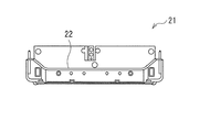
- a support stabilization member 21 (weight) for adding weight downward may be attached to the lower portion of the stand 2. Thereby, it becomes possible to improve the stability when the main body 1 is placed directly on the installation surface 90. For example, even if the installation surface 90 is an inclined surface inclined about 15 ° on the back side, it is possible to improve the installation stability so that the main body 1 does not fall down.
- the support stabilization member 21 has a fitting portion 22 and may be detachable from the lower portion of the stand 2.
- the top of the stand 2 is attached to the main body 1 so that it can be opened and closed by a hinge 4.
- the stand 2 is opened to the main body 1.
- the stand 2 is closed with respect to the main body 1.
- the stand 2 is attached to a wall surface via the wall attachment member 5, for example.
- the support stabilizing member 21 may be removed from the stand 2.
- the display device 100 includes a plurality of circuits related to the display panel 10. It is preferable that the plurality of circuits are divided and arranged both inside the main body 1 and inside the stand 2. For example, it is preferable to arrange a circuit (circuit board) that generates heat relatively on the stand 2 side. Thereby, the influence of the heat with respect to the display panel 10 by a circuit can be reduced.
- a circuit circuit board
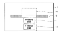
- FIG. 6 shows a configuration example of the circuit unit 40 inside the main body 1.
- the circuit unit 40 may include a video processing circuit 41 and a panel control circuit 42.
- the circuit unit 40 may be provided with a circuit for driving the vibrators 31L and 31R.
- a cover that covers the circuit unit 40 may be attached to the back side of the main body 1.
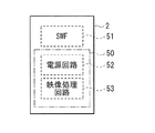
- FIG. 7 shows a configuration example of the circuit unit 50 inside the stand 2.
- the circuit unit 50 may include, for example, a power supply circuit 52 and a video processing circuit 53.
- the power supply circuit 52 is a circuit (circuit board) that is relatively easy to generate heat, and is preferably arranged on the stand 2 side.
- a subwoofer (SWF) 51 may be provided in the upper part.
- the vibrators 31L and 31R provided inside the main body 1 may function as a speaker that bears the mid-high range, and the subwoofer 51 may bear the low range.
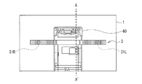
- FIG. 8 shows a configuration example of the back side of the main body 1.
- FIG. 9 shows a cross-sectional configuration example taken along the line AA ′ of FIG.
- FIG. 10 shows an enlarged cross-sectional configuration example of the lower central region 20 of FIG.
- FIG. 11 shows a simplified cross-sectional configuration example of FIG. In FIG. 11, for the sake of explanation, only necessary components are simplified and illustrated, and other components are not shown. 8 to 11, the cover that covers the circuit unit 40 is omitted on the back side of the main body 1.
- the main body 1 includes a display panel 10, an inner plate 11, a back glass 14, and a back chassis 12 in order from the front side to the back side.
- the main body 1 includes a bezel 15 that is an outer frame.
- the main part of the bezel 15 is preferably a metal member such as aluminum, but may be partially a resin member as shown in FIGS.
- the outer peripheral part of the display panel 10, the inner plate 11, and the rear glass 14 is sandwiched by the bezel 15.
- the inner plate 11 and the back chassis 12 are preferably members excellent in heat dissipation characteristics and heat diffusion characteristics.
- the inner plate 11 and the back chassis 12 are preferably metal members such as aluminum.
- the inner plate 11 is disposed with a space 13 between the display panel 10.
- the vibrators 31L and 31R constitute a part of the sound generator.
- the vibrators 31 ⁇ / b> L and 31 ⁇ / b> R may be actuators that are attached to the inner plate 11 and generate sound by vibrating the display panel 10 through the space 13 between the inner plate 11 and the display panel 10.
- the receiving member 60 is attached to the lower central portion 20 (FIG. 9) of the main body 1. As shown in FIG. 11, the receiving member 60 has a gap 65 between the installation surface 90 and the main body 1, in other words, other than the receiving member 60 with respect to the installation surface 90 at the lower part of the main body 1.
- the main body 1 is supported so that the portion is in a floating state.
- the receiving member 60 is preferably a material that easily absorbs an impact when the main body 1 is installed on the installation surface 90.
- the receiving member 60 is preferably a rubber foot, for example.
- the receiving member 60 is fixed to the back chassis 12 via an intermediate mounting member 63.
- the receiving member 60 and the intermediate mounting member 63 are fixed to each other with a screw 61 as a fixing member.
- the intermediate mounting member 63 and the back chassis 12 are fixed to each other with a screw 62 as a fixing member. Further, the screw 62 is fixed to the stud 64.
- the back glass 14, the back chassis 12, and the intermediate mounting member 63 are connected by the screws 62 and the studs 64.
- the receiving member 60 is made of a material that easily absorbs impact, and the receiving member 60 is fixed to the back chassis 12 via the screws 61 and 62 and the intermediate mounting member 63, whereby the main body 1 is installed on the installation surface 90.
- the structure is such that an impact when installed to the display panel 10 is not easily transmitted to the display panel 10.
- the bottom surface of the receiving member 60 may have a shape inclined at a predetermined inclination angle ⁇ with respect to the horizontal plane 92 as shown in FIG. 10, for example. Thereby, stability when the main body 1 is inclined and arranged with respect to the horizontal plane 92 can be improved.
- FIG. 12 shows a configuration example of the lower part of the circuit unit 40 in the main body 1.
- FIG. 13 shows a cross-sectional configuration example taken along the line BB ′ of FIG.
- FIG. 14 shows a simplified cross-sectional configuration example of FIG.
- FIG. 15 shows a cross-sectional configuration example of a comparative example corresponding to the cross-sectional configuration example of FIG.
- FIG. 14 and FIG. 15 only necessary components are illustrated in a simplified manner for the sake of explanation, and illustration of other components is omitted. 12 to 15, the cover that covers the circuit unit 40 is omitted on the back side of the main body 1.
- the circuit unit 40 in the main body 1 may be provided with communication circuit units 71 and 72 that perform wireless communication.
- the communication circuit unit 71 may be a circuit unit for Wi-Fi (registered trademark), for example.
- the communication circuit unit 72 may be a circuit unit for Bluetooth (registered trademark), for example.
- the communication circuit units 71 and 72 have an antenna unit for transmitting and receiving the radio signal 73.
- the communication circuit units 71 and 72 may be arranged in the vicinity of the bezel 15 as the outer frame on the back side of the main body 1.
- the bezel 15 is partially It is preferable to use a member through which the radio signal 73 can pass.
- the lower central region of the bezel 15 may be a resin member 15B through which the radio signal 73 can pass, and the other main parts of the bezel 15 may be formed of an aluminum member 15A.
- the communication circuit units 71 and 72 may be arranged so that at least the antenna units of the communication circuit units 71 and 72 are positioned corresponding to the resin member 15B. As a result, as shown in FIG. 14, the wireless signal 73 passes through the resin member 15 ⁇ / b> B, thereby enabling wireless communication with the front side of the main body 1.
- the wireless signal 73 is shielded by the aluminum member 15A as shown in FIG.
- a conventional general display device by providing an installation space in the lower part of the main body 1, it may be possible to perform wireless communication without providing a configuration region by the resin member 15 ⁇ / b> B.
- the configuration region by the resin member 15B it is possible to wirelessly communicate with the front side of the main body 1 without providing an installation space in the lower part of the main body 1.
- this technique can also take the following structures.
- a display device comprising: a receiving member attached to a lower portion of the main body and supporting the main body so that a gap is formed between the installation surface and the main body.
- the main body further includes a back chassis disposed on the back side with respect to the display panel;
- the display device according to (1), wherein the receiving member is fixed to the back chassis via an intermediate mounting member.
- a plurality of circuits related to the display panel The display device according to any one of (1) to (3), wherein the plurality of circuits are arranged both inside the main body and inside the stand.
- the main body further includes an outer frame partially formed of a member through which a radio signal can pass,
- the main body further includes an inner plate disposed between the display panel and the back chassis and disposed with a space with respect to the display panel,
- the sound generation unit includes a vibrator that is attached to the inner plate and generates a sound by vibrating the display panel through a space between the inner plate and the display panel. Display device.
Landscapes
- Engineering & Computer Science (AREA)
- General Engineering & Computer Science (AREA)
- Theoretical Computer Science (AREA)
- Computer Hardware Design (AREA)
- Physics & Mathematics (AREA)
- General Physics & Mathematics (AREA)
- Human Computer Interaction (AREA)
- Mechanical Engineering (AREA)
- Multimedia (AREA)
- Signal Processing (AREA)
- Acoustics & Sound (AREA)
- Devices For Indicating Variable Information By Combining Individual Elements (AREA)
- Transforming Electric Information Into Light Information (AREA)
Abstract
本開示の表示装置は、表示パネルと音発生部とを有する本体と、設置面に対して前記本体を背面側から支持するスタンドと、前記本体の下部に取り付けられ、前記設置面と前記本体との間に隙間が空くように前記本体を支持する受け部材とを備える。
Description
本開示は、表示装置に関する。
テレビジョン用途等の表示装置では、表示部を含む本体の下部にスピーカーが配置されていることが多い。一般に、このような表示装置では、床面等の設置面に設置する場合、本体の下部にスタンドが取り付けられる。
一般に、表示装置にスタンドを取り付けた場合、本体下部と設置面との間には、ある程度の設置空間が生じる。設置空間があることで、スピーカーからの音を効果的に前側に発することを可能にしている。
本体下部の設置空間を少なくすることが可能な表示装置を提供することが望ましい。
本開示の一実施の形態に係る表示装置は、表示パネルと音発生部とを有する本体と、設置面に対して本体を背面側から支持するスタンドと、本体の下部に取り付けられ、設置面と本体との間に隙間が空くように本体を支持する受け部材とを備えたものである。
本開示の一実施の形態に係る表示装置では、本体の下部に取り付けられた受け部材によって、本体が支持される。
本開示の一実施の形態に係る表示装置によれば、本体の下部に受け部材を取り付けるようにしたので、本体下部の設置空間を少なくすることが可能となる。
なお、ここに記載された効果は必ずしも限定されるものではなく、本開示中に記載されたいずれかの効果であってもよい。
なお、ここに記載された効果は必ずしも限定されるものではなく、本開示中に記載されたいずれかの効果であってもよい。
以下、本開示の実施の形態について図面を参照して詳細に説明する。なお、説明は以下の順序で行う。
1.第1の実施の形態
1.1 表示装置の全体構成(図1~図7)
1.2 本体の受け構造(図8~図11)
1.3 無線通信に対応する構造(図12~図15)
1.4 効果
2.その他の実施の形態
1.第1の実施の形態
1.1 表示装置の全体構成(図1~図7)
1.2 本体の受け構造(図8~図11)
1.3 無線通信に対応する構造(図12~図15)
1.4 効果
2.その他の実施の形態
<1.第1の実施の形態>
[1.1 表示装置の全体構成]
図1は、本開示の第1の実施の形態に係る表示装置100の背面側の一構成例を簡略化して示している。図2は、表示装置100の側方側の一構成例を示している。図3は、表示装置100の背面側の一構成例を示している。
[1.1 表示装置の全体構成]
図1は、本開示の第1の実施の形態に係る表示装置100の背面側の一構成例を簡略化して示している。図2は、表示装置100の側方側の一構成例を示している。図3は、表示装置100の背面側の一構成例を示している。
本実施の形態に係る表示装置は、本体1と、設置面90に対して本体1を背面側から支持するスタンド2とを備えている。
本体1は、後述する図10~図11に示す表示パネル10を有している。表示パネル10は、例えばOLED(Organic Light Emitting Diode)を用いた有機ELディスプレイパネルである。
なお、本実施の形態において、表示パネル10によって画像を表示する側を前側、表示パネル10とは反対側を背面側とする。
なお、本実施の形態において、表示パネル10によって画像を表示する側を前側、表示パネル10とは反対側を背面側とする。
本体1は、後述する図8~図11に示す受け構造を有し、後述する受け部材60を介して床面等の設置面90に対して直置きすることが可能な構成とされている。
本体1の背面の中央部には、水平方向に板状の補強部材3が設けられている。本体1の内部には、補強部材3が設けられた位置に対応する一部の領域に、図3に示したように、音を発生させるための加振器(アクチュエータ)31L,31Rが設けられている。なお、加振器31L,31Rを設ける位置は、図3に示した位置に限定されるものではない。ただし、加振器31L,31Rをステレオスピーカーとして機能させることを考慮し、前側から見て本体1の右側半分の領域における略中央部に加振器31R、本体1の左側半分の領域における略中央部に加振器31Lが設けられていることが好ましい。本体1の右側半分の領域における略中央部において、加振器31Rは複数、設けられていてもよい。本体1の左側半分の領域における略中央部において、加振器31Lは複数、設けられていてもよい。
スタンド2の下部には、下方向に重量を付加する支持安定化部材21(重り)が取り付けられていてもよい。これにより、本体1を、設置面90に直置きした場合の安定性を向上させることが可能となる。例えば、設置面90が背面側に15°程度傾斜した傾斜面であっても、本体1が転倒することのないように、設置の安定性を向上させることが可能となる。支持安定化部材21は、図4に示したように嵌合部22を有し、スタンド2の下部に対して着脱可能となっていてもよい。
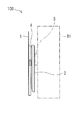
スタンド2は、上部がヒンジ4によって本体1に対して開閉可能に取り付けられている。図1、および図2に示したように、本体1を設置面90に対して直置きする場合には、スタンド2を本体1に対して開いた状態とする。一方、例えば、図5に示したように、表示装置100を壁91等に取り付ける場合には、スタンド2を本体1に対して閉じた状態とする。壁91等に取り付ける場合には、例えば、壁取り付け部材5を介してスタンド2を壁面に取り付ける。壁91等に取り付ける場合には、支持安定化部材21はスタンド2から外した状態にしてもよい。
表示装置100は、表示パネル10に関わる複数の回路を備えている。複数の回路は、本体1の内部とスタンド2の内部との双方に分割されて配置されていることが好ましい。例えば、相対的に熱を発生しやすい回路(回路基板)をスタンド2側に配置することが好ましい。これにより、回路による表示パネル10に対する熱の影響を低減できる。
図6は、本体1の内部における回路部40の一構成例を示している。
回路部40は、例えば、映像処理回路41と、パネル制御回路42とを有していてもよい。その他、回路部40には加振器31L,31Rを駆動するための回路等が設けられていてもよい。なお、本体1の背面側には、回路部40を覆うカバーが取り付けられていてもよい。
回路部40は、例えば、映像処理回路41と、パネル制御回路42とを有していてもよい。その他、回路部40には加振器31L,31Rを駆動するための回路等が設けられていてもよい。なお、本体1の背面側には、回路部40を覆うカバーが取り付けられていてもよい。
図7は、スタンド2の内部における回路部50の一構成例を示している。
回路部50は、例えば、電源回路52と、映像処理回路53とを有していてもよい。電源回路52は、相対的に熱を発生しやすい回路(回路基板)であり、スタンド2側に配置することが好ましい。
回路部50は、例えば、電源回路52と、映像処理回路53とを有していてもよい。電源回路52は、相対的に熱を発生しやすい回路(回路基板)であり、スタンド2側に配置することが好ましい。
また、スタンド2の内部において、例えば上部には、サブウーファ(SWF)51が設けられていてもよい。本体1の内部に設けられた加振器31L,31Rが中高音域を担い、サブウーファ51が低音域を担うスピーカーとして機能させてもよい。
[1.2 本体の受け構造]
図8は、本体1の背面側の一構成例を示している。図9は、図8のA-A’線の断面構成例を示している。図10は、図9の中央領域下部20の断面構成例を拡大して示している。図11は、図10の断面構成例を簡略化して示している。図11では、説明上、必要とされる構成要素のみを簡略化して図示し、他の構成要素の図示を省略している。
なお、図8~図11では、本体1の背面側において、回路部40を覆うカバーを省略した状態で図示している。
図8は、本体1の背面側の一構成例を示している。図9は、図8のA-A’線の断面構成例を示している。図10は、図9の中央領域下部20の断面構成例を拡大して示している。図11は、図10の断面構成例を簡略化して示している。図11では、説明上、必要とされる構成要素のみを簡略化して図示し、他の構成要素の図示を省略している。
なお、図8~図11では、本体1の背面側において、回路部40を覆うカバーを省略した状態で図示している。
本体1は、前側から背面側へ向かって順に、表示パネル10と、インナープレート11と、背面ガラス14と、バックシャーシ12とを備えている。
また、本体1は、外枠であるベゼル15を備えている。ベゼル15は、例えば、主要部分がアルミ等の金属部材であることが好ましいが、後述する図12~図14に示すように、部分的に樹脂部材であってもよい。表示パネル10とインナープレート11と背面ガラス14は、ベゼル15によって外周部分が挟持されている。
インナープレート11とバックシャーシ12は、放熱特性、熱拡散特性に優れた部材であることが好ましい。例えば、インナープレート11とバックシャーシ12は、アルミ等の金属部材であることが好ましい。
インナープレート11は、図13に示すように、表示パネル10に対して空間13を空けて配置されている。加振器31L,31Rは、音発生部の一部を構成している。加振器31L,31Rは、インナープレート11に取り付けられ、インナープレート11と表示パネル10との間の空間13を介して表示パネル10を振動させて音を発生させるアクチュエータであってもよい。これにより、従来の一般的な表示装置では、本体1の下部の設置空間からスピーカーの音を前側に発しているのに対し、本実施の形態では、表示パネル10自体から前側に音が発生する。すなわち、本実施の形態では、音を前側に発生させるために本体1の下部に設置空間を設ける必要がない構造とされている。
受け部材60は、本体1の中央領域下部20(図9)に取り付けられている。受け部材60は、図11に示したように、設置面90と本体1との間に隙間65が空くように、換言すれば、本体1の下部において、設置面90に対して受け部材60以外の部分が浮いた状態となるように、本体1を支持する。
受け部材60は、本体1を設置面90へ設置したときの衝撃を吸収しやすい素材であることが好ましい。受け部材60は、例えばゴム足状のものであることが好ましい。
受け部材60は、中間取り付け部材63を介してバックシャーシ12に固定されている。受け部材60と中間取り付け部材63は、固定部材としてのねじ61で互いに固定されている。中間取り付け部材63とバックシャーシ12は、固定部材としてのねじ62で互いに固定されている。さらに、ねじ62は、スタッド64に固定されている。ねじ62とスタッド64とによって、背面ガラス14とバックシャーシ12と中間取り付け部材63とが接続されている。
このように、受け部材60を衝撃を吸収しやすい素材とし、かつ、受け部材60をねじ61,62と中間取り付け部材63とを介してバックシャーシ12に固定することで、本体1を設置面90へ設置したときの衝撃が表示パネル10に伝わりにくい構造とされている。
受け部材60の底面は、例えば図10に示したように、水平面92に対して所定の傾斜角θで傾斜した形状であってもよい。これにより、本体1を水平面92に対して傾斜させて配置にした場合の安定性を向上させることができる。
[1.3 無線通信に対応する構造]
図12は、本体1における回路部40の下部の一構成例を示している。図13は、図12のB-B’線の断面構成例を示している。図14は、図13の断面構成例を簡略化して示している。図15は、図14の断面構成例に対応する比較例の断面構成例を示している。図14および図15では、説明上、必要とされる構成要素のみを簡略化して図示し、他の構成要素の図示を省略している。
なお、図12~図15では、本体1の背面側において、回路部40を覆うカバーを省略した状態で図示している。
図12は、本体1における回路部40の下部の一構成例を示している。図13は、図12のB-B’線の断面構成例を示している。図14は、図13の断面構成例を簡略化して示している。図15は、図14の断面構成例に対応する比較例の断面構成例を示している。図14および図15では、説明上、必要とされる構成要素のみを簡略化して図示し、他の構成要素の図示を省略している。
なお、図12~図15では、本体1の背面側において、回路部40を覆うカバーを省略した状態で図示している。
本体1における回路部40には、無線通信を行う通信回路部71,72が設けられてもよい。通信回路部71は、例えばWi-Fi(登録商標)用の回路部であってもよい。通信回路部72は、例えばBluetooth(ブルートゥース)(登録商標)用の回路部であってもよい。通信回路部71,72は、無線信号73を送受信するためのアンテナ部を有している。
通信回路部71,72は、図12~図14に示したように、本体1の背面側において外枠であるベゼル15の近傍に配置されてもよい、この場合、ベゼル15を、部分的に無線信号73が通過可能な部材で構成することが好ましい。例えば、ベゼル15の下部の中央領域を無線信号73が通過可能な樹脂部材15Bとし、その他のベゼル15の主要な部分をアルミ部材15Aで構成してもよい。
そして、少なくとも、通信回路部71,72のアンテナ部が樹脂部材15Bに対応する位置となるように、通信回路部71,72を配置してもよい。これにより、図14に示したように、無線信号73が樹脂部材15Bを通過することで、本体1の前側に対して無線通信が可能となる。
ベゼル15に樹脂部材15Bによる構成領域を設けなかった場合、図15に示したように、アルミ部材15Aによって無線信号73が遮蔽されるので、本体1の前側に対して無線通信が困難となる。従来の一般的な表示装置では、本体1の下部に設置空間を設けることで、樹脂部材15Bによる構成領域を設けることなく無線通信を行うことが可能になり得る。これに対して、本実施の形態では、樹脂部材15Bによる構成領域を設けたことで、本体1の下部に設置空間を設けることなく、本体1の前側に対して無線通信が可能となる。
[1.4 効果]
以上のように、本実施の形態によれば、本体1の下部に受け部材60を取り付けるようにしたので、本体下部の設置空間を少なくすることが可能となる。
以上のように、本実施の形態によれば、本体1の下部に受け部材60を取り付けるようにしたので、本体下部の設置空間を少なくすることが可能となる。
なお、本明細書に記載された効果はあくまでも例示であって限定されるものではなく、また他の効果があってもよい。
<2.その他の実施の形態>
本開示による技術は、上記各実施の形態の説明に限定されず種々の変形実施が可能である。
本開示による技術は、上記各実施の形態の説明に限定されず種々の変形実施が可能である。
例えば、本技術は以下のような構成を取ることもできる。
(1)
表示パネルと音発生部とを有する本体と、
設置面に対して前記本体を背面側から支持するスタンドと、
前記本体の下部に取り付けられ、前記設置面と前記本体との間に隙間が空くように前記本体を支持する受け部材と
を備える
表示装置。
(2)
前記本体は、前記表示パネルに対して背面側に配置されたバックシャーシをさらに有し、
前記受け部材は、中間取り付け部材を介して前記バックシャーシに固定されている
上記(1)に記載の表示装置。
(3)
前記受け部材は、前記本体の中央領域の下部に取り付けられている
上記(1)または(2)に記載の表示装置。
(4)
前記表示パネルに関わる複数の回路をさらに備え、
前記複数の回路が、前記本体の内部と前記スタンドの内部との双方に配置されている
上記(1)ないし(3)のいずれか1つに記載の表示装置。
(5)
前記スタンドの下部に取り付けられ、前記スタンドの下方向に重量を付加する支持安定化部材、をさらに備える
上記(1)ないし(4)のいずれか1つに記載の表示装置。
(6)
前記本体は、部分的に無線信号が通過可能な部材で構成された外枠をさらに有し、
前記本体の背面側において前記外枠の近傍に配置され、無線通信を行う通信回路部をさらに備える
上記(1)ないし(5)のいずれか1つに記載の表示装置。
(7)
前記本体は、前記表示パネルと前記バックシャーシとの間に配置されると共に前記表示パネルに対して空間を空けて配置されたインナープレートをさらに有し、
前記音発生部は、前記インナープレートに取り付けられ、前記インナープレートと前記表示パネルとの間の空間を介して前記表示パネルを振動させて音を発生させる加振器を含む
上記(2)に記載の表示装置。
本出願は、日本国特許庁において2016年12月27日に出願された日本特許出願番号第2016-253587号を基礎として優先権を主張するものであり、この出願のすべての内容を参照によって本出願に援用する。
当業者であれば、設計上の要件や他の要因に応じて、種々の修正、コンビネーション、サブコンビネーション、および変更を想到し得るが、それらは添付の請求の範囲やその均等物の範囲に含まれるものであることが理解される。
Claims (7)
- 表示パネルと音発生部とを有する本体と、
設置面に対して前記本体を背面側から支持するスタンドと、
前記本体の下部に取り付けられ、前記設置面と前記本体との間に隙間が空くように前記本体を支持する受け部材と
を備える
表示装置。 - 前記本体は、前記表示パネルに対して背面側に配置されたバックシャーシをさらに有し、
前記受け部材は、中間取り付け部材を介して前記バックシャーシに固定されている
請求項1に記載の表示装置。 - 前記受け部材は、前記本体の中央領域下部に取り付けられている
請求項1に記載の表示装置。 - 前記表示パネルに関わる複数の回路をさらに備え、
前記複数の回路が、前記本体の内部と前記スタンドの内部との双方に配置されている
請求項1に記載の表示装置。 - 前記スタンドの下部に取り付けられ、前記スタンドの下方向に重量を付加する支持安定化部材、をさらに備える
請求項1に記載の表示装置。 - 前記本体は、部分的に無線信号が通過可能な部材で構成された外枠をさらに有し、
前記本体の背面側において前記外枠の近傍に配置され、無線通信を行う通信回路部をさらに備える
請求項1に記載の表示装置。 - 前記本体は、前記表示パネルと前記バックシャーシとの間に配置されると共に前記表示パネルに対して空間を空けて配置されたインナープレートをさらに有し、
前記音発生部は、前記インナープレートに取り付けられ、前記インナープレートと前記表示パネルとの間の空間を介して前記表示パネルを振動させて音を発生させる加振器を含む
請求項2に記載の表示装置。
Priority Applications (4)
| Application Number | Priority Date | Filing Date | Title |
|---|---|---|---|
| JP2018558876A JP7024731B2 (ja) | 2016-12-27 | 2017-11-09 | 表示装置 |
| EP17885876.7A EP3564932A4 (en) | 2016-12-27 | 2017-11-09 | DISPLAY DEVICE |
| US16/338,772 US10989352B2 (en) | 2016-12-27 | 2017-11-09 | Display apparatus |
| CN201780064570.9A CN109891480B (zh) | 2016-12-27 | 2017-11-09 | 显示装置 |
Applications Claiming Priority (2)
| Application Number | Priority Date | Filing Date | Title |
|---|---|---|---|
| JP2016253587 | 2016-12-27 | ||
| JP2016-253587 | 2016-12-27 |
Publications (1)
| Publication Number | Publication Date |
|---|---|
| WO2018123288A1 true WO2018123288A1 (ja) | 2018-07-05 |
Family
ID=62707165
Family Applications (1)
| Application Number | Title | Priority Date | Filing Date |
|---|---|---|---|
| PCT/JP2017/040402 WO2018123288A1 (ja) | 2016-12-27 | 2017-11-09 | 表示装置 |
Country Status (5)
| Country | Link |
|---|---|
| US (1) | US10989352B2 (ja) |
| EP (1) | EP3564932A4 (ja) |
| JP (1) | JP7024731B2 (ja) |
| CN (1) | CN109891480B (ja) |
| WO (1) | WO2018123288A1 (ja) |
Cited By (2)
| Publication number | Priority date | Publication date | Assignee | Title |
|---|---|---|---|---|
| CN111447518A (zh) * | 2020-05-12 | 2020-07-24 | 枣庄学院 | 一种基于舞台演出的古琴桌电源音箱安装组件 |
| WO2022138128A1 (ja) | 2020-12-21 | 2022-06-30 | ソニーグループ株式会社 | 表示装置 |
Families Citing this family (1)
| Publication number | Priority date | Publication date | Assignee | Title |
|---|---|---|---|---|
| USD848386S1 (en) * | 2016-12-28 | 2019-05-14 | Sony Corporation | Television receiver |
Citations (6)
| Publication number | Priority date | Publication date | Assignee | Title |
|---|---|---|---|---|
| JP2002032028A (ja) * | 2000-07-18 | 2002-01-31 | Matsushita Electric Ind Co Ltd | 画像表示装置 |
| JP3096746U (ja) * | 2003-03-27 | 2003-10-03 | 船井電機株式会社 | 液晶テレビジョン |
| JP2005184393A (ja) * | 2003-12-18 | 2005-07-07 | Alps Electric Co Ltd | 音響再生装置 |
| JP2009194541A (ja) * | 2008-02-13 | 2009-08-27 | Tetsuo Murayama | 薄型構造の薄型テレビ |
| JP2014095858A (ja) * | 2012-11-12 | 2014-05-22 | Sharp Corp | 薄型表示装置 |
| JP2015152719A (ja) * | 2014-02-13 | 2015-08-24 | ソニー株式会社 | 表示装置 |
Family Cites Families (41)
| Publication number | Priority date | Publication date | Assignee | Title |
|---|---|---|---|---|
| JPH11258580A (ja) * | 1998-03-16 | 1999-09-24 | Hitachi Ltd | 液晶表示モニタ |
| US6191940B1 (en) * | 1999-01-06 | 2001-02-20 | His-Kuang Ma | Foldable and portable planar display device |
| JP2001061194A (ja) | 1999-08-23 | 2001-03-06 | Authentic Ltd | パネル型スピーカ |
| KR100367586B1 (ko) * | 1999-10-08 | 2003-01-10 | 엘지전자 주식회사 | 평판 모니터 |
| GB2360901A (en) | 2000-03-29 | 2001-10-03 | Nokia Mobile Phones Ltd | A loudspeaker which uses an electronic display as a diaphragm |
| JP2003005660A (ja) * | 2001-06-22 | 2003-01-08 | Casio Comput Co Ltd | 情報処理装置 |
| WO2003079718A1 (fr) * | 2002-03-15 | 2003-09-25 | Sharp Kabushiki Kaisha | Dispositif d'affichage d'image |
| KR20050073879A (ko) * | 2004-01-12 | 2005-07-18 | 엘지전자 주식회사 | Dmb tv용 지지부 구조 |
| DE102004032223A1 (de) | 2004-07-02 | 2006-01-19 | Siemens Ag | Audiovisuelle Anordnung |
| US20060050471A1 (en) * | 2004-09-03 | 2006-03-09 | Yin-Hung Chen | Monitor frame structure |
| JP3966320B2 (ja) * | 2004-09-28 | 2007-08-29 | セイコーエプソン株式会社 | 電気光学装置及び電子機器 |
| JP4396726B2 (ja) * | 2007-05-23 | 2010-01-13 | ソニー株式会社 | 表示装置 |
| JP2009162811A (ja) * | 2007-12-28 | 2009-07-23 | Orion Denki Kk | 表示装置 |
| JP4798462B2 (ja) * | 2008-01-22 | 2011-10-19 | ソニー株式会社 | 画像表示装置 |
| JP4935738B2 (ja) * | 2008-03-28 | 2012-05-23 | 富士通株式会社 | 電子機器およびパネル |
| CN101661689B (zh) * | 2008-08-29 | 2012-06-20 | 鸿富锦精密工业(深圳)有限公司 | 显示装置 |
| CN201436650U (zh) * | 2009-04-15 | 2010-04-07 | 王明俊 | 视频装置 |
| KR101749302B1 (ko) * | 2010-12-24 | 2017-06-21 | 삼성전자주식회사 | 디스플레이 장치 |
| US8649166B2 (en) * | 2011-01-11 | 2014-02-11 | Z124 | Multi-positionable portable computer |
| CN102762254B (zh) * | 2011-02-18 | 2015-09-23 | 麦德托尼克公司 | 模块化医疗设备编程器 |
| CN201956006U (zh) * | 2011-03-21 | 2011-08-31 | 京东方科技集团股份有限公司 | 平板显示装置 |
| KR101840029B1 (ko) * | 2011-09-06 | 2018-05-08 | 삼성디스플레이 주식회사 | 표시장치 |
| CN102384348A (zh) * | 2011-11-24 | 2012-03-21 | 冠捷显示科技(厦门)有限公司 | 可壁挂式电视底座 |
| JP2013130600A (ja) * | 2011-12-20 | 2013-07-04 | Sanyo Electric Co Ltd | 薄型表示装置 |
| CN107426515B (zh) * | 2011-12-27 | 2020-09-29 | 索尼公司 | 连接装置 |
| JP5395924B2 (ja) * | 2012-03-30 | 2014-01-22 | 株式会社東芝 | 電子機器 |
| JP5362069B2 (ja) * | 2012-04-25 | 2013-12-11 | 株式会社東芝 | 電子機器 |
| JP5627032B2 (ja) * | 2012-04-27 | 2014-11-19 | レノボ・シンガポール・プライベート・リミテッド | 筐体用材料、当該筐体用材料の製造方法、当該筐体用材料を用いた電子機器用筐体、当該電子機器用筐体の製造方法、当該電子機器用筐体を用いた電子機器 |
| JP5358717B2 (ja) | 2012-06-04 | 2013-12-04 | 日立コンシューマエレクトロニクス株式会社 | 平面型表示装置 |
| JP2014016564A (ja) | 2012-07-11 | 2014-01-30 | Sony Corp | 表示装置 |
| US9602760B2 (en) * | 2012-07-25 | 2017-03-21 | Dell Products, Lp | Modular display monitor |
| CN103809669A (zh) | 2012-11-09 | 2014-05-21 | 辉达公司 | 用于平板电子设备的后盖和具有该后盖的平板电子设备 |
| JP6015497B2 (ja) * | 2013-03-01 | 2016-10-26 | 船井電機株式会社 | 表示装置 |
| JP2014191059A (ja) * | 2013-03-26 | 2014-10-06 | Sony Corp | 表示装置 |
| US9255661B2 (en) * | 2013-05-31 | 2016-02-09 | Hewlett-Packard Development Company, L.P. | Adjusters to control lower joints and upper joints |
| CN103672335B (zh) * | 2013-09-25 | 2016-02-03 | 青岛海信电器股份有限公司 | 电视机 |
| KR102229137B1 (ko) * | 2014-05-20 | 2021-03-18 | 삼성디스플레이 주식회사 | 표시장치 |
| US9838781B2 (en) * | 2014-05-27 | 2017-12-05 | Nokia Technologies Oy | Apparatus and method for reducing sound coupling |
| CN105739610A (zh) * | 2014-12-12 | 2016-07-06 | 鸿富锦精密工业(武汉)有限公司 | 一体机 |
| JP6700783B2 (ja) * | 2015-01-22 | 2020-05-27 | キヤノン株式会社 | 表示装置 |
| CN205229614U (zh) * | 2015-11-30 | 2016-05-11 | Tcl海外电子(惠州)有限公司 | 显示模组 |
-
2017
- 2017-11-09 EP EP17885876.7A patent/EP3564932A4/en active Pending
- 2017-11-09 WO PCT/JP2017/040402 patent/WO2018123288A1/ja unknown
- 2017-11-09 US US16/338,772 patent/US10989352B2/en active Active
- 2017-11-09 CN CN201780064570.9A patent/CN109891480B/zh active Active
- 2017-11-09 JP JP2018558876A patent/JP7024731B2/ja active Active
Patent Citations (6)
| Publication number | Priority date | Publication date | Assignee | Title |
|---|---|---|---|---|
| JP2002032028A (ja) * | 2000-07-18 | 2002-01-31 | Matsushita Electric Ind Co Ltd | 画像表示装置 |
| JP3096746U (ja) * | 2003-03-27 | 2003-10-03 | 船井電機株式会社 | 液晶テレビジョン |
| JP2005184393A (ja) * | 2003-12-18 | 2005-07-07 | Alps Electric Co Ltd | 音響再生装置 |
| JP2009194541A (ja) * | 2008-02-13 | 2009-08-27 | Tetsuo Murayama | 薄型構造の薄型テレビ |
| JP2014095858A (ja) * | 2012-11-12 | 2014-05-22 | Sharp Corp | 薄型表示装置 |
| JP2015152719A (ja) * | 2014-02-13 | 2015-08-24 | ソニー株式会社 | 表示装置 |
Non-Patent Citations (1)
| Title |
|---|
| See also references of EP3564932A4 * |
Cited By (2)
| Publication number | Priority date | Publication date | Assignee | Title |
|---|---|---|---|---|
| CN111447518A (zh) * | 2020-05-12 | 2020-07-24 | 枣庄学院 | 一种基于舞台演出的古琴桌电源音箱安装组件 |
| WO2022138128A1 (ja) | 2020-12-21 | 2022-06-30 | ソニーグループ株式会社 | 表示装置 |
Also Published As
| Publication number | Publication date |
|---|---|
| US10989352B2 (en) | 2021-04-27 |
| JPWO2018123288A1 (ja) | 2019-10-31 |
| CN109891480A (zh) | 2019-06-14 |
| JP7024731B2 (ja) | 2022-02-24 |
| US20200224818A1 (en) | 2020-07-16 |
| CN109891480B (zh) | 2021-10-01 |
| EP3564932A4 (en) | 2020-07-15 |
| EP3564932A1 (en) | 2019-11-06 |
Similar Documents
| Publication | Publication Date | Title |
|---|---|---|
| JP6468731B2 (ja) | 曲面ディスプレイ装置 | |
| JP6010013B2 (ja) | 表示装置 | |
| WO2018123288A1 (ja) | 表示装置 | |
| JP2022009473A (ja) | フラットパネルスピーカおよび表示装置 | |
| JP2010256607A (ja) | 画像表示装置 | |
| JP2009267577A (ja) | 薄型表示装置 | |
| JP5166973B2 (ja) | スピーカ装置及びその駆動方法 | |
| WO2017104118A1 (ja) | スピーカ装置 | |
| JP2020092306A (ja) | スピーカ装置 | |
| JP5203329B2 (ja) | スタンド及び表示装置 | |
| WO2015093445A1 (ja) | 表示装置及びテレビジョン受信機 | |
| JP5563861B2 (ja) | スタンド及び表示装置 | |
| KR102622979B1 (ko) | 표시 장치 | |
| JP5552285B2 (ja) | スタンドおよび表示装置 | |
| JP2008109605A (ja) | 情報機器のスピーカシステム | |
| JPH11243591A (ja) | スピーカ装置 | |
| JP2015091020A (ja) | 薄型表示装置 | |
| JP2015144479A (ja) | 薄型表示装置 | |
| WO2014157644A1 (ja) | 表示装置の筐体およびテレビジョン受像機 | |
| JP2021083064A (ja) | スピーカーシステム | |
| JP2008211746A (ja) | 画像表示装置 | |
| JP2012080338A (ja) | 画像表示装置 | |
| JP2020001463A (ja) | 車載機器の取付装置 | |
| JP2008271142A (ja) | スピーカ装置 | |
| JP2006229605A (ja) | スピーカを有する機器、表示装置 |
Legal Events
| Date | Code | Title | Description |
|---|---|---|---|
| 121 | Ep: the epo has been informed by wipo that ep was designated in this application |
Ref document number: 17885876 Country of ref document: EP Kind code of ref document: A1 |
|
| ENP | Entry into the national phase |
Ref document number: 2018558876 Country of ref document: JP Kind code of ref document: A |
|
| NENP | Non-entry into the national phase |
Ref country code: DE |
|
| ENP | Entry into the national phase |
Ref document number: 2017885876 Country of ref document: EP Effective date: 20190729 |