WO2018100939A1 - Machine d'enfoncement - Google Patents
Machine d'enfoncement Download PDFInfo
- Publication number
- WO2018100939A1 WO2018100939A1 PCT/JP2017/038895 JP2017038895W WO2018100939A1 WO 2018100939 A1 WO2018100939 A1 WO 2018100939A1 JP 2017038895 W JP2017038895 W JP 2017038895W WO 2018100939 A1 WO2018100939 A1 WO 2018100939A1
- Authority
- WO
- WIPO (PCT)
- Prior art keywords
- valve
- push lever
- chamber
- pressure
- trigger
- Prior art date
Links
Images


Classifications
-
- B—PERFORMING OPERATIONS; TRANSPORTING
- B25—HAND TOOLS; PORTABLE POWER-DRIVEN TOOLS; MANIPULATORS
- B25C—HAND-HELD NAILING OR STAPLING TOOLS; MANUALLY OPERATED PORTABLE STAPLING TOOLS
- B25C1/00—Hand-held nailing tools; Nail feeding devices
- B25C1/04—Hand-held nailing tools; Nail feeding devices operated by fluid pressure, e.g. by air pressure
- B25C1/047—Mechanical details
-
- B—PERFORMING OPERATIONS; TRANSPORTING
- B25—HAND TOOLS; PORTABLE POWER-DRIVEN TOOLS; MANIPULATORS
- B25C—HAND-HELD NAILING OR STAPLING TOOLS; MANUALLY OPERATED PORTABLE STAPLING TOOLS
- B25C1/00—Hand-held nailing tools; Nail feeding devices
- B25C1/04—Hand-held nailing tools; Nail feeding devices operated by fluid pressure, e.g. by air pressure
- B25C1/041—Hand-held nailing tools; Nail feeding devices operated by fluid pressure, e.g. by air pressure with fixed main cylinder
- B25C1/043—Trigger valve and trigger mechanism
Definitions
- the present invention relates to a structure of a driving machine for driving a stopper member.
- the driving machine is used for driving a stopper member into a plate material as a material to be driven, for example, wood, gypsum board, steel plate or the like.
- the stopper member includes a nail, a screw, and the like as an example.
- the driving machine includes a nailing machine and a screw driving machine as an example.
- the nailing machine performs an operation of driving a nail into a material to be driven in one direction with a strong driving force.
- the screw driving machine is designed to drive the screw into the driven material in one direction and a distance shorter than the total length of the screw, rotate the screw driven into the driven material, and screw the screw into the driven material. Do.
- the structure of what uses compressed air as a power source of a driving machine is described in Patent Document 1, for example.
- the driving machine described in Patent Document 1 includes a main body, a handle, a nose, a cylinder, a piston, a push lever, a trigger, a pressure accumulation chamber, and a piston upper chamber.
- the cylinder and the piston upper chamber are provided in the main body.
- the piston can reciprocate within the cylinder.
- a driver blade is fixed to the piston.
- the handle is connected to the main body, and the nose is fixed to the main body.
- the pressure accumulating chamber is provided over the inside of the main body and the handle.
- the trigger is provided at a connection portion between the main body and the handle.
- the push lever is attached to the nose.
- the push lever is movable relative to the nose.
- the push lever is biased in a direction away from the main body by a spring. Then, when driving the stopper member into the plate member positioned below the push lever, the operator presses the tip of the push lever against the plate member with the nose facing down. By this operation, the push lever comes into contact with the plate material and moves in a direction approaching the main body along the nose.
- the trigger is provided at a connection portion between the main body and the handle portion, that is, a portion where the operator holds the handle portion. The trigger can rotate around the support shaft, and the trigger rotates when the operator operates the trigger.
- the driving machine starts driving operation when both the push lever is pressed against the plate material and the operator operates the trigger.
- an operator can drive a fastener member correctly to a desired location by operating a trigger.
- compressed air is supplied to the piston upper chamber by the operation of the trigger, and the driving machine starts driving operation.
- the operator presses the push lever against the plate material, and then the operator operates the trigger so that the driving machine performs driving, that is, the single driving operation is performed once for the stopper member. It is suitable for work that requires driving to be driven.
- the operator may perform the driving operation with the driving machine by bringing the push lever into contact with the plate material or the like while maintaining the state in which the trigger is operated in advance, that is, performing the continuous driving operation. it can.
- the driving machine starts driving operation.
- Such a continuous driving operation is suitable for a case where the stopper member is driven continuously at a plurality of locations in the plate material at short time intervals.
- the driving operation of the stopper member can be performed particularly efficiently. The worker selects whether to perform a single shot operation or a continuous shot operation according to the work content.
- An object of this invention is to provide the driving machine which can suppress driving a fastener member in the position shifted
- the driving machine is provided with an operation member operated by an operator, a contact member that comes into contact with the driven material, and an operation member.
- the driving member is driven into the driven material.
- a driving machine having a striking unit and a first pressure chamber that operates the striking unit with the pressure of a compressed fluid when the operation member is operated and the contact member comes into contact with the workpiece.
- a valve body operable to open and close a first path for sending the compressed fluid to the first pressure chamber, a control mechanism having a first state and a second state for controlling opening and closing of the valve body, and the control
- a restriction mechanism that permits and restricts switching between the first state and the second state of the mechanism, and the first state is that the operation member is operated and the contact member is When the contact with the driven material is established, the valve body
- the first path is opened, and the second state is that at least one of the operation member being operated and the contact member being in contact with the driven material is not established.
- the first path is closed by the valve body, and the restriction mechanism is predetermined from a reference time when both the operation member is operated and the contact member is separated from the driven material.
- the operation member When it is within the time, the operation member is operated with a first function that allows the contact member to contact the workpiece and the control mechanism to change from the second state to the first state. And when the contact member is in contact with the driven material when the contact member exceeds the predetermined time from the reference time when the contact member is separated from the driven material. Changes from the second state to the first state. And a, a second function of regulating the.
- the driving machine of one embodiment can suppress a shift of a position where the stopper member is driven into the driven material.
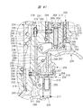
- FIG. 2 is an enlarged cross-sectional view showing a structural example of a trigger valve and a push lever valve in a state where both a trigger and a push lever are off in the driving machine shown in FIG. .
- FIG. 3 is a cross-sectional view illustrating a main part of a specific example 1 of the restriction mechanism illustrated in FIG. 2 in a state where a lock pin is in an initial position.
- FIG. 4 is a cross-sectional view illustrating a main part of the first specific example of the restriction mechanism illustrated in FIG.
- FIG. 4 is a cross-sectional view illustrating a main part of a specific example 1 of the restriction mechanism illustrated in FIG.
- FIG. 6 is a cross-sectional view illustrating a main part of the first specific example of the restriction mechanism illustrated in FIG. 2 in a state where the lock pin is moved from the restriction position toward the initial position.
- FIG. 3 is a cross-sectional view illustrating a state of the push lever valve after a short time has elapsed since the trigger valve, the push lever valve, and the restriction mechanism illustrated in FIG.
- FIG. 3 is a cross-sectional view illustrating a state of the push lever valve after a long time has elapsed since the trigger valve, the push lever valve, and the restriction mechanism illustrated in FIG.
- FIG. 3 is a specific example 1 of the trigger valve, the push lever valve, and the restriction mechanism shown in FIG.
- FIG. 3 is a specific example 1 of the trigger valve, the push lever valve, and the restriction mechanism shown in FIG. 2, and is a cross-sectional view illustrating a state in which the push lever is pushed up after a short time has elapsed since turning on only the trigger.
- region A in FIG. FIG. 3 is a specific example 1 of the trigger valve, the push lever valve, and the restriction mechanism shown in FIG. 2, and is a cross-sectional view illustrating a state in which the push lever is pushed up after a short time has elapsed since turning on only the trigger.
- FIG. 3 is a specific example 1 of the trigger valve, the push lever valve, and the restriction mechanism shown in FIG.
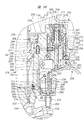
- FIG. 12 is a plan sectional view showing the operation of the restriction mechanism shown in FIG. 11. It is a perspective view of the contact protrusion provided in the push lever and block shown in FIG. It is an expanded sectional view which shows the principal part of FIG.
- FIG. 12 is a plan sectional view showing a relative position of a contact protrusion provided on the push lever and the block shown in FIG. 11.
- FIG. 4 is a specific example 2 of a restriction mechanism used in the driving machine of FIG. 1, and is a cross-sectional view of a main part in which a push lever is in an on state.
- FIG. 4 is a specific example 2 of a trigger valve, a push lever valve, and a restriction mechanism used in the driving machine of FIG.
- FIG. 4 is a specific example 2 of a restriction mechanism used in the driving machine of FIG. 1, and is a cross-sectional view of a main part in which a push lever is in an off state.
- FIG. 4 is a specific example 2 of a restriction mechanism used in the driving machine of FIG. 1, and is a cross-sectional view of a main part in which a push lever is in an off state.
- FIG. 5 is a specific example 2 of a trigger valve, a push lever valve, and a restriction mechanism used in the driving machine of FIG. 1, and is a cross-sectional view in a state where the trigger valve is turned on and the push lever valve is turned off.
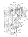
- FIG. 4 is a specific example 3 of the trigger valve, push lever valve, and regulating mechanism used in the driving machine of FIG. It is sectional drawing which expands and shows the principal part of FIG.
- FIG. 6 is a specific example 3 of the trigger valve, push lever valve, and regulating mechanism used in the driving machine of FIG. 1, and is a cross-sectional view in a state where both the trigger valve and the push lever valve are on. It is sectional drawing which expands and shows the principal part of FIG. FIG.
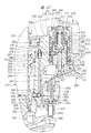
- FIG. 4 is a specific example 3 of a trigger valve, a push lever valve, and a restriction mechanism used in the driving machine of FIG. 1, and is a cross-sectional view in a state where the trigger valve is on and the operation of the push lever valve is restricted. It is sectional drawing which expands and shows the principal part of FIG. It is sectional drawing which shows the whole driving machine which is Embodiment 2 in this invention.
- FIG. 28 is an enlarged cross-sectional view of a hitting portion shown in FIG. 27. It is a fragmentary sectional view which shows the specific example 4 of the control mechanism provided in the driving machine shown in FIG. It is an expanded sectional view of the timeout valve which the specific example 4 of a control mechanism has.
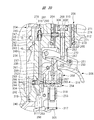
- FIG. 28 is a partial cross-sectional view of the driving machine shown in FIG. 27 in a state where compressed air is introduced.
- FIG. 28 is a partial cross-sectional view showing a state where compressed air is introduced into the driving machine shown in FIG. 27 and the lock valve is operated.
- FIG. 28 is a partial cross-sectional view of the driving machine shown in FIG. 27 with the trigger turned on.
- FIG. 28 is an overall cross-sectional view of the driving machine shown in FIG. 27 in a state where the hitting unit performs a hitting operation.
- FIG. 28 is a partial cross-sectional view of the driving machine shown in FIG.
- FIG. 28 is a partial cross-sectional view showing a state in which a predetermined time has passed since the trigger is turned on and the push lever is turned off in the driving machine shown in FIG. 27.
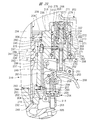
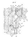
- FIG. 1 is a cross-sectional view showing a driving machine 100 corresponding to Embodiment 1.
- the driving machine 100 discloses a nailing machine as an example.
- the driving machine 100 drives a nail 80, which is an example of a stopper member, into a material 81 to be driven.
- FIG. 1 shows a cross-sectional view before the nail 80 is driven into the driven material 81.
- FIG. 1 is a cross-sectional view including an axis 82 of the driving machine 100 and is a view showing a part of the driving machine 100 as seen through.
- the driving machine 100 shown in FIG. 1 shows an example in which a nail 80 is driven in a vertical direction with respect to the driven material 81. For this reason, the axis 82 in FIG. 1 is arranged along the vertical direction.
- the vertical direction is the vertical direction in FIG.
- the driving machine 100 shown in FIG. 1 is an example in which a driving force downward in FIG. 1 is applied to the nail 80 and the nail 80 is driven into the driven
- the driving machine 100 includes a main housing 10, a handle 50, a nose 12, and a hitting unit 16.
- the main housing 10 has a substantially cylindrical shape extending in the vertical direction in FIG.
- the handle 50 is connected to the main housing 10 and protrudes outward in the radial direction of the main housing 10.
- the nose 12 is attached to the end of the main housing 10 in the longitudinal direction.
- the longitudinal direction of the main housing 10 and the direction of the axis line 82 are described as the vertical direction.
- the longitudinal direction of the main housing 10 is the same as the direction along the axis 82, the direction parallel to the axis 82, or the direction of the axis 82.
- the direction along the axis 82, the direction parallel to the axis 82, and the direction of the axis 82 are technically synonymous.
- the direction approaching the nose 12 is represented by any term of downward, downward, downward, and downward in this embodiment.
- the direction away from the nose 12 is represented by any term of upward, upward, upward, and upward in this embodiment.
- an air valve 51 is provided at an end portion of the handle 50 opposite to the end portion connected to the main housing 10.
- the air valve 51 is detachable from an air hose for supplying compressed air.
- the air hose is not shown.
- it may be described as the front-rear direction.
- separates from the air valve 51 among the front-back direction may be represented by the term in any one among the front, the front side, and the front.
- the direction which approaches the air valve 51 among front-back directions is represented by any term among back, back, and back. Note that, in FIG. 1 in which the driving machine 100 is viewed from the side, an imaginary line 83 and an axis 82 intersect each other.
- the striking portion 16 is provided inside the main housing 10.
- the striking portion 16 is a mechanism that applies a driving force to the nail 80 toward the lower side in FIG. 1 using compressed air.
- a cylinder 15 is provided in the main housing 10.
- the center line of the cylinder 15 is represented as an axis 82 in FIG.
- a pressure accumulation chamber 50 ⁇ / b> A is provided in the handle 50, the upper side of the cylinder 15, and the outer periphery of the cylinder 15.
- the compressed air supplied from the air hose is stored in the pressure accumulating chamber 50A.
- a known pressure reducing valve may be provided in the air path between the air valve 51 and the pressure accumulating chamber 50A. The pressure reducing valve adjusts the pressure of the compressed air using a differential pressure between the spring pressure and the air pressure. That is, the pressure of the compressed air supplied into the pressure accumulating chamber 50A can be adjusted.
- the piston 14 is provided in the cylinder 15, and the piston 14 can reciprocate in the direction of the axis 82 in the cylinder 15.
- An exhaust valve chamber 103 is provided above the cylinder 15 in the main housing 10.
- a piston upper chamber 84 is provided between the exhaust valve chamber 103 and the piston 14.
- the exhaust valve chamber 103 is connected to the cylinder valve chamber 101.
- An exhaust passage 85 is provided above the cylinder 15 in the main housing 10.
- a port 86 that connects the exhaust passage 85 and the piston upper chamber 84 is provided.
- An exhaust valve 102 is provided between the exhaust valve chamber 103 and the port 86. The exhaust valve 102 opens and closes the port 86.
- a bumper 89 is provided on the cylinder 15 in the main housing 10.
- the bumper 89 is a synthetic rubber as an example.
- a piston lower chamber 15 ⁇ / b> A is provided below the piston 14 in the cylinder 15.
- a return chamber 10 ⁇ / b> A is provided between the main housing 10 and the outer peripheral surface of the cylinder 15.
- the cylinder 15 has a check valve 90 for connecting and blocking the piston lower chamber 15A and the return chamber 10A.
- a bumper 87 is provided between the cylinder 15 and the nose 12.
- the bumper 87 is a buffer member made of synthetic rubber.
- a return elastic member 88 is provided in the main housing 10, and the elastic member 88 biases the cylinder 15 upward.
- the elastic member 88 is, for example, a metal compression spring.
- the operation of the driving machine 100 driving the nail 80 downward is performed by moving the piston 14 and the driver blade 11 in the direction of the axis 82.
- the driver blade 11 moves downward in FIG. 1, the nail 80 is driven into the driven material 81.
- FIG. 1 the state before the driver blade 11 drives the nail 80 into the driven material 81, that is, the initial state is shown.
- the nose 12 protrudes downward from the main housing 10 in FIG.
- the nose 12 has an injection path, and the driver blade 11 is movable in the direction of the axis 82 in the injection path.
- the lower end of the driver blade 11 moves up and down in the injection path in FIG.
- a push lever 13 is attached to the nose 12, and the push lever 13 can move in the vertical direction along the nose 12.
- the push lever 13 moves upward along the nose 12.
- a magazine 60 that accommodates a plurality of nails is attached to the rear of the nose 12.
- the nail 80 sent to the injection path is driven into the driven material 81 by the driver blade 11.
- the piston 14 is fixed to the upper side of the driver blade 11, and the piston 14 moves up and down in the cylinder 15.
- the striking portion 16 includes a piston 14, a driver blade 11, and a piston upper chamber 84.
- the end of the cylinder 15 is pressed against the bumper 89 by the force of the elastic member 88, and the port 321 is closed.
- the port 321 is formed between the end of the cylinder 15 and the bumper 89. When the port 321 is closed, the pressure accumulation chamber 50A and the piston upper chamber 84 are blocked.
- the piston 14 and the driver blade 11 are urged upward by the air pressure in the piston lower chamber 15A.
- both the trigger plunger 21 and the push lever plunger 31 are off, the piston 14 is pressed against the bumper 89, and the piston 14 and the driver blade 11 are stopped at the top dead center shown in FIG.
- the off of the trigger plunger 21 means that the operating force applied to the trigger 41 is released as shown in FIG. 2 and the trigger valve 20 is closed.
- the trigger plunger 21 is stopped at the initial position.
- the push lever plunger 31 is turned off when the operating force of the push lever 13 is not transmitted to the push lever valve 30 and the push lever valve 30 is closed.
- the push lever plunger 31 is off.
- the push lever plunger 31 is stopped at the initial position as shown in FIG.
- the driving operation of the driving machine 100 includes an operation in which the cylinder 15 moves downward in FIG. 1 and an operation in which the driver blade 11 and the piston 14 move from the top dead center toward the bottom dead center.
- the on state of the trigger plunger 21 is a state where the operating force of the trigger 41 shown in FIG. 8 is transmitted to the trigger valve 20 and the trigger valve 20 is opened.
- the push lever plunger 31 is turned on, a force that moves the push lever 13 in the direction of the axis 115 is transmitted to the push lever valve 30 to open the push lever valve 30.
- a pressure chamber 30 ⁇ / b> A is provided at a connection location between the main housing 10 and the handle 50.
- the compressed air in the pressure accumulating chamber 50A flows into the cylinder valve chamber 101 via the pressure chamber 30A.
- the push lever valve 30 is disposed downstream of the trigger valve 20 in the flow direction of the air that supplies the compressed air of the pressure accumulating chamber 50 ⁇ / b> A to the cylinder valve chamber 101.
- the air pressure in the cylinder valve chamber 101 rises, the cylinder 15 moves downward against the urging force of the elastic member 88 to open the port 321, and the pressure accumulation chamber 50 ⁇ / b> A and the piston upper chamber 84 communicate with each other.
- the compressed air in the pressure accumulating chamber 50A is supplied to the piston upper chamber 84, the air pressure in the piston upper chamber 84 is increased, and the piston 14 is lowered in FIG.
- the piston 14 and the driver blade 11 move to the bottom dead center and stop, and the driving operation of the driving machine 100 is completed.
- the cylinder valve 99 is closed, the pressure accumulation chamber 50A and the piston upper chamber 84 are shut off, and the air pressure in the cylinder valve chamber 101 decreases. To do.
- the cylinder 15 is raised by the biasing force of the elastic member 88.
- the compressed air in the cylinder valve chamber 101 and the exhaust valve chamber 103 is exhausted to the outside of the main housing 10.
- the exhaust valve 102 is operated to open the port 86, and the compressed air in the piston upper chamber 84 is discharged to the outside of the main housing 10 through the exhaust passage 85.
- the air pressure in the piston upper chamber 84 decreases.
- the air in the return chamber 10A flows into the piston lower chamber 15A.
- the piston 14 and the driver blade 11 rise from the bottom dead center toward the top dead center, the piston 14 contacts the bumper 89 as shown in FIG. 1, and the piston 14 stops at the top dead center.
- the driving machine 100 starts the operation of driving the nail 80 into the driven material 81 by moving the driver blade 11 by supplying compressed air to the piston upper chamber 84.
- this driving machine 100 the structure of the path for supplying and blocking the compressed air in the pressure accumulating chamber 50A to the piston upper chamber 84 and the structure around the path will be described.
- the driving machine 100 switches between a state in which compressed air is supplied to the piston upper chamber 84 and a state in which the supply of compressed air to the piston upper chamber 84 is blocked by the operation of the trigger valve 20 and the push lever valve 30.
- the driving machine 100 supplies compressed air to the piston upper chamber 84 and starts driving operation.
- the driving machine 100 cuts off the supply of compressed air to the piston upper chamber 84 and ends the driving operation.
- Both the trigger valve 20 and the push lever valve 30 are provided in the vicinity of the connecting portion between the handle 50 and the main housing 10. On / off of the trigger valve 20 and on / off of the push lever valve 30 can be switched independently.
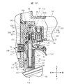
- FIG. 2 is an enlarged sectional view showing the structure around the trigger valve 20 and the push lever valve 30.
- FIG. 2 shows an example in which the trigger valve 20 and the push lever valve 30 are both off.
- the trigger valve 20 is turned on and off by operating the trigger 41.
- the trigger 41 is attached to the main housing 10 so as to be rotatable about a trigger shaft 41A.
- the trigger 41 is provided below the trigger valve 20 in the direction of the axis 82.
- a guide member 91 is attached to the main housing 10.
- An elastic member 92 is provided, and the elastic member 92 urges the trigger 41 clockwise around the trigger shaft 41A in FIG.
- the trigger 41 is urged by the elastic member 92 and stops at a position where it contacts the guide member 91 as shown in FIG.
- the trigger valve 20 has a function of connecting and blocking the pressure accumulation chamber 50A and the pressure chamber 30A.
- the trigger valve 20 When the trigger valve 20 is on, that is, in the open state, the pressure accumulation chamber 50A and the pressure chamber 30A are connected.
- the trigger valve 20 When the trigger valve 20 is off, that is, in the closed state, the pressure accumulation chamber 50A and the pressure chamber 30A are shut off.
- the trigger valve 20 includes a cylindrical guide portion 22 attached to the handle 50, a trigger valve chamber 20A provided in the guide portion 22, a guide portion 22, and a pressure accumulating chamber 50A and a trigger valve chamber 20A. , A ball-shaped valve member 23 that opens and closes the port 93, and a trigger plunger 21 that is movably provided in the shaft hole 95 of the guide portion 22.
- the guide portion 22 guides the trigger plunger 21 so as to move in the vertical direction in FIG. A part of the trigger plunger 21 in the longitudinal direction is disposed outside the guide portion 22, specifically, outside the handle 50.
- the valve member 23 is pressed against the guide portion 22 by the air pressure in the pressure accumulating chamber 50 ⁇ / b> A and closes the port 93.
- the trigger valve chamber 20A is connected to the pressure chamber 30A.
- a flange 24 is provided at a position arranged outside the handle 50, and a seal member 94 is attached to the outer peripheral surface of the trigger plunger 21.
- the seal member 94 seals the shaft hole 95.
- the seal member 94 is a synthetic rubber O-ring.
- the valve member 23 When no operating force is applied to the trigger 41 and the trigger 41 is stopped at the initial position as shown in FIG. 2, the valve member 23 is pressed against the guide portion 22 by the air pressure of the pressure accumulating chamber 50A, and the valve member 23 Is blocking the port 93. That is, the trigger valve 20 is off, in other words, closed. When the trigger valve 20 is off, the compressed air in the pressure accumulating chamber 50A does not flow into the pressure chamber 30A.
- the flange 24 does not push the seal member 94 into the shaft hole 95. That is, the seal member 94 does not seal the shaft hole 95. For this reason, the compressed air in the trigger valve chamber 20 ⁇ / b> A and the pressure chamber 30 ⁇ / b> A is discharged from the shaft hole 95 to the outside of the main housing 10.
- the trigger 41 rotates counterclockwise in FIG. 2 and the trigger 41 is pressed against the trigger plunger 21. Then, the trigger plunger 21 moves upward in FIG. 2, pushes up the valve member 23, and the port 93 opens as shown in FIG. The flange 24 pushes the seal member 94 into the shaft hole 95, and the seal member 94 seals the shaft hole 95. That is, the trigger valve 20 is on, in other words, an open state.
- the trigger valve 20 is on, the compressed air in the pressure accumulating chamber 50A flows into the pressure chamber 30A via the port 93 and the trigger valve chamber 20A.
- the push lever valve 30 is provided between the cylinder 15 and the trigger valve 20 in the main housing 10.
- the push lever valve 30 urges a pressure chamber 30A, a push lever valve chamber 30B, a push lever plunger 31, a cylindrical valve body 32 in which the push lever plunger 31 is movably accommodated, a valve member 33, and the valve member 33.
- a spring 34 is provided.
- the push lever plunger 31 and the valve member 33 are arranged concentrically around the axis 115. In the side view of the driving machine 100 illustrated in FIG. 1, the axis 115 is parallel to the axis 82.
- the push lever plunger 31 and the valve member 33 are relatively movable in the vertical direction in FIG. 2 and are disposed so as to contact each other.
- FIGS. 2, 4, 5, 6, 8, and 10 is a direction parallel to the axis 115.
- the front-rear direction in FIGS. 2, 4, 5, 6, 8, and 10 is a direction intersecting the axis 115, specifically, a direction perpendicular to the axis 115.
- the pressure chamber 30 ⁇ / b> A is provided in the valve body 32.
- a port 96 is provided in the valve body 32, and the port 96 connects the pressure chamber 30A and the push lever valve chamber 30B.
- the valve body 32 has an exhaust passage 151 connected to the push lever valve chamber 30B.
- a seal member 97 is attached to the valve member 33, and the seal member 97 opens and closes the port 96.
- the spring 34 urges the valve member 33 downward in FIG. 2, and the valve member 33 is pressed against the push lever plunger 31.
- an outer cylinder member 35 is provided, and the outer cylinder member 35 is supported by the guide member 91 and is movable in the direction of the axis 115 with respect to the main housing 10, that is, in the vertical direction in FIG.
- a part of the valve body 32 is disposed in the outer cylinder member 35.
- a lock pin engaging portion 36 is provided on the outer peripheral surface of the outer cylinder member 35 at a location close to the trigger shaft 41 ⁇ / b> A in the direction of the axis 115. As shown in FIG. 9, the lock pin engaging portion 36 has a lock pin engaging surface 36A, an inclined surface 36B, and a vertical surface 36C.
- the lock pin locking surface 36 ⁇ / b> A is perpendicular to the axis 115
- the inclined surface 36 ⁇ / b> B is inclined with respect to the axis 115
- the vertical surface 36 ⁇ / b> C is parallel to the axis 115.
- a flange 112 is provided at the lower end of the push lever plunger 31.
- An elastic member 98 is provided between the flange 112 and the valve body 32.
- the elastic member 98 is, for example, a metal compression coil spring.
- the elastic member 98 has a vertical elastic force in FIG.
- the push lever 13 has a push lever arm portion 131, and the push lever arm portion 131 has a hook 110.
- a stopper 111 is provided on the guide member 91.
- the push lever plunger 31 that is pressed downward in FIG. 2 is pressed against the outer cylinder member 35 by the urging force of the elastic member 98. Further, the outer cylinder member 35 is pressed against the push lever arm portion 131.
- the hook 110 is engaged with the stopper 111, the push lever 13 is stopped at the initial position, and the push lever plunger 31 is stopped at the initial position.
- the valve body 32 is urged upward in FIG. 2 by the elastic force of the elastic member 98 and is pressed against the step 113 to stop.
- the step portion 113 is provided at a connection location between the main housing 10 and the handle 50.
- the push lever plunger 31 opens the exhaust passage 151, and the driving flow path 10 ⁇ / b> B is connected to the outside of the main housing 10 via the push lever valve chamber 30 ⁇ / b> B and the exhaust passage 151.
- the push lever valve 30 when the push lever valve 30 is on, that is, in the open state, the compressed air in the pressure chamber 30A is supplied to the cylinder valve chamber 101 via the push lever valve chamber 30B and the driving flow path 10B. Then, the cylinder 15 descends in FIG. 15 to open the port 321, and the compressed air in the pressure accumulating chamber 50 ⁇ / b> A is sent to the piston upper chamber 84. For this reason, the striking unit 16 performs a driving operation.
- the driving device 100 supplies compressed air to the piston upper chamber 84 and the driving unit 16 drives the nail 80.
- the driving machine 100 when at least one of the trigger valve 20 and the push lever valve 30 is off, compressed air is not supplied to the piston upper chamber 84, and the driving machine 100 performs the driving operation. Not performed.
- the driving operation using the driving machine 100 includes a third driving operation in addition to a single driving operation that is the first driving operation and a continuous driving operation that is the second driving operation.
- the single shot operation is to push the push lever 13 against the workpiece 81 to turn on the push lever valve 30 and then turn on the trigger valve 20 to operate the hitting portion 16.
- the operator separates the push lever 13 from the driven material 81 to turn off the push lever valve 30 and turn off the trigger valve 20. Thereafter, the above operation is repeated, and the nail 80 is driven into the workpiece 81.
- the continuous firing operation alternately repeats an operation of switching the push lever valve 30 from off to on and an operation of switching the push lever valve 30 from on to off while the trigger valve 20 is kept on.
- the nail 80 is driven into the driven material 81.
- the third driving operation is to turn on the push lever valve 30 after the trigger valve 20 is turned on and operate the hitting portion 16.
- the operator separates the push lever 13 from the driven material 81 to turn off the push lever valve 30 and turn off the trigger valve 20. Thereafter, the above operation is repeated, and the nail 80 is driven into the workpiece 81.
- the operation can be performed particularly efficiently by performing the continuous driving operation.
- the compressed air is discharged from the piston upper chamber 84, and the piston 14 and the driver blade 11 are moved downward. Ascending from the dead center, the piston 14 and the driver blade 11 stop at the top dead center shown in FIG. 1, that is, at the initial position.
- the timing for pressing the push lever 13 against the workpiece 81 is left to the operator. For this reason, the waiting time from when the trigger valve 20 is turned on and the push lever valve 30 is turned off until the push lever valve 30 switches from off to on, that is, the time interval is not constant. The waiting time varies depending on the situation. Even during the waiting time, the push lever 13 may be close to the workpiece 81.
- the push lever valve 30 is switched from OFF to ON, and from a desired position on the driven material 81. The nail 80 may be driven into the detached position.
- the striking unit 16 In order to prevent the nail 80 from being driven into a position deviated from the desired position in the driven material 81, the striking unit 16 is restricted from driving the nail 80 when the waiting time exceeds a predetermined time. do it. On the other hand, in order to prevent the workability when the hitting portion 16 next drives the nail 80 into the driven material 81, it is desirable that the restriction on the hitting of the hitting portion 16 can be easily and quickly released. .
- the driving machine 100 described above has a regulating mechanism 154 for regulating the driving operation.
- the restriction mechanism 154 has a function of restricting the operation of the push lever plunger 31 and a function of releasing the restriction.
- the regulation mechanism 154 regulates the operation of switching the push lever valve 30 from off to on when a predetermined time has elapsed from the time when the push lever valve 30 is off and the trigger valve 20 is on. It is a timeout mechanism.
- examples where both the push lever valve 30 is off and the trigger valve 20 is on include the first example and the second example.
- the first example is a case where the trigger valve 20 is switched from off to on from the state where both the push lever valve 30 and the trigger valve 20 are off.
- the second example is a case where the push lever valve 30 is switched from on to off from the state where the push lever valve 30 is on and the trigger valve 20 is on.
- specific examples of the restriction mechanism 154 that can be provided in the driving machine 100 will be sequentially described.
- the regulation mechanism 154 includes an outer cylinder member 35 and a pin driving unit 70.
- the pin driver 70 has a first function and a second function.
- the first function allows the push lever valve 30 to be switched from off to on within a predetermined time from when both the push lever valve 30 is off and the trigger valve 20 is on. It is a function.
- the second function restricts the push lever valve 30 from switching from off to on after a predetermined time has elapsed since both the push lever valve 30 is off and the trigger valve 20 is on. It is a function to do.
- the main housing 10 has a wall portion 155 that forms the return chamber 10 ⁇ / b> A, and the pin driving portion 70 is provided on the wall portion 155.
- the pin drive unit 70 is disposed between the cylinder 15 and the valve body 32 in the radial direction of the cylinder 15.
- the pin driving unit 70 has a pin 71.
- the pin 71 is an element that restricts the push lever 13 from moving upward in FIG.
- the pin drive unit 70 operates the pin 71 using compressed air and restricts the push lever 13 from moving upward in FIG. 2 according to the state of the trigger 41. Further, the restriction given to the push lever 13 by the pin 71 can be easily released.
- the pin driver 70 is shown in FIGS. 3A, 3B, 3C, and 3D.
- the pin drive unit 70 includes an outer cylinder part 72, an inner cylinder part 73, and an outer wall part 75.
- the pin 71 is movable rightward and leftward about the axis 114. 2, 3, 4, 6, 8, and 10, the axis 114 intersects the axis 115, and is disposed at a right angle as an example.
- the pin 71 moves to the right in any of FIGS. 3A, 3B, 3C, and 3D.
- the pin 71 moves in any of FIGS. 2, 3, 4, 6, 8, and 10. To move backwards.
- the pin 71 moves rearward, the pin 71 approaches the valve body 32 in the direction of the axis 114.
- the pin 71 moves to the left in any of FIG. 3A, FIG. 3B, FIG. 3C, or FIG. 3D.
- the pin 71 moves in any of FIG. 2, FIG. 3, FIG. 4, FIG. Is to move forward.
- the pin 71 moves forward, the pin 71 moves away from the valve body 32 in the direction of the axis 114.
- the outer cylinder member 35 is stopped at the initial position as shown in FIG.
- the pin 71 moves from the initial position shown in FIG. 3A to the right along the axis 114 shown in FIG. 3B, and the pin 71 stops at the restriction position shown in FIGS. 3C and 5. It is possible.
- the pin driving unit 70 operates using the compressed air in the pressure chamber 30A.
- a control flow path 10 ⁇ / b> C is provided in the main housing 10.
- the pin driving unit 70 has a first air chamber 70A, and the control flow channel 10C connects the first air chamber 70A and the pressure chamber 30A.
- 3A shows a state in which the pin 71 is stopped at the initial position
- FIG. 3B shows a state in which the pin 71 has started to move rightward from the initial position
- FIG. 3C shows a state in which the pin 71 has stopped at the restricted position
- the push lever 13 When the pin 71 is in the initial position of FIG. 3A, the push lever 13 can be switched from the off state to the on state. When the pin 71 is in the restriction position of FIG. 3C, the push lever 13 cannot be switched from off to on.
- the outer cylinder part 72 constitutes an outer shell of the pin driving part 70.
- An inner cylinder portion 73 is provided in the outer cylinder portion 72.
- the first air chamber 70 ⁇ / b> A is formed between the outer cylinder portion 72 and the inner cylinder portion 73.
- the outer cylinder part 72, the inner cylinder part 73, and the pin 71 are disposed concentrically around the axis 114.
- a first end portion of the outer cylinder portion 72 in the direction of the axis 114 is closed by a wall portion 116.
- An outer wall portion 75 is fixed in a second end portion located opposite to the wall portion 116 in the direction of the axis 114 of the outer cylinder portion 72.
- the inner cylinder portion 73 is disposed between the wall portion 116 and the outer wall portion 75 in the direction of the axis 114.
- An end portion close to the wall portion 116 in the direction of the axis 114 of the inner cylinder portion 73 is closed by the wall portion 76. Further, the end of the inner cylinder portion 73 opposite to the wall portion 76 in the direction of the axis 114 is closed by the outer wall portion 75. For this reason, the inner cylinder part 73 is fixed to the outer cylinder part 72 in the direction of the axis 114.
- the outer wall 75 has a shaft hole 117 centered on the axis 114.
- the pin 71 has a tip portion 711, a piston portion 712 and a central portion 713.
- the central portion 713 is disposed between the tip portion 711 and the piston portion 712 in the direction of the axis 114.
- the piston part 712 and the center part 713 are arranged in the inner cylinder part 73 so as to be movable in the direction of the axis 114.
- the tip 711 is movably disposed in the shaft hole 117.
- a spring 77 is provided between the piston part 712 and the outer wall part 75 in the inner cylinder part 73.
- the spring 77 is, for example, a metal compression coil spring, and the spring 77 biases the pin 71 toward the wall 76.
- a second air chamber 70 ⁇ / b> B is formed between the piston portion 712 and the wall portion 76.
- the wall portion 76 has a passage 118 and a small hole 76A.
- the passage 118 and the small hole 76A are connected, the passage 118 is connected to the first air chamber 70A, and the small hole 76A is connected to the second air chamber 70B.
- a passage 119 penetrating the inner cylinder portion 73 in the radial direction is provided. The passage 119 connects the first air chamber 70A and the second air chamber 70B.
- a check valve 73 ⁇ / b> A is attached to the outer peripheral surface of the inner cylinder portion 73.
- the check valve 73A is a synthetic rubber ring as an example.
- the check valve 73A opens the passage 119, the compressed air in the second air chamber 70B is allowed to be discharged to the first air chamber 70A via the passage 119.
- the check valve 73A closes the passage 119, the compressed air in the first air chamber 70A is prevented from flowing into the second air chamber 70B via the passage 119.
- the pin driving unit 70 can move and stop the pin 71 in the direction of the axis 114 according to the air pressure in the second air chamber 70B.
- the flow of compressed air between the pressure chamber 30A and the second air chamber 70B is performed via the first air chamber 70A.
- the flow of compressed air between the first air chamber 70A and the second air chamber 70B is performed via at least one of the small hole 76A or the passage 119.
- the flow rate of air passing through the small holes 76A that is, the flow rate per unit time is set smaller than the flow rate of air passing through the passage 119.
- the pin 71 is urged away from the valve body 32 in the direction of the axis 114 by the urging force of the spring 77. Further, when compressed air is introduced into the second air chamber 70B, the air pressure in the second air chamber 70B moves in the direction toward the valve body 32 in the direction of the axis 114 against the elastic force of the spring 77. Further, when the air pressure in the second air chamber 70B decreases, the pin 71 moves by the urging force of the spring 77, contacts the wall 76 as shown in FIG. 3A, and stops at the initial position.
- the pressure chamber 30A is at atmospheric pressure. Since the first air chamber 70A communicates with the pressure chamber 30A, the first air chamber 70A also becomes atmospheric pressure, and compressed air is not introduced into the second air chamber 70B. For this reason, the pin 71 is pushed by the urging force of the spring 77 and stops at the initial position in FIG. 3A.
- the compressed air in the pressure accumulating chamber 50A is introduced into the pressure chamber 30A.
- a part of the compressed air in the pressure chamber 30A is introduced into the first air chamber 70A.
- the air pressure in the second air chamber 70B is lower than the pressure at which the check valve 73A opens, and the check valve 73A is closed.
- the compressed air in the first air chamber 70A gradually flows into the second air chamber 70B through the passage 118 and the small hole 76A, and the pressure in the second air chamber 70B gradually increases.
- the pin 71 moves to the right along the axis 114.
- the center part 713 contacts the outer wall part 75, and the pin 71 stops in a control position.
- the pressure in the second air chamber 70B is equal to the pressure in the first air chamber 70A and the pressure chamber 30A. That is, the pin 71 can be moved from the initial position to the restricted position by introducing the compressed air in the pressure chamber 30A into the second air chamber 70B via the first air chamber 70A.
- the moving speed of the pin 71 is in accordance with the flow rate of the air flowing through the small hole 76A.
- the operation when the trigger valve 20 is switched from on to off and the compressed air in the pressure chamber 30A is exhausted to the outside of the main housing 10 will be described.
- the pressure in the pressure chamber 30A decreases, the pressure in the first air chamber 70A also decreases, and the compressed air in the second air chamber 70B passes through the small holes 76A and the passage 118 and passes through the first air chamber 70A as shown in FIG. 3D.
- the check valve 73A is opened due to a decrease in the air pressure in the first air chamber 70A, and a part of the compressed air in the second air chamber 70B is discharged to the first air chamber 70A through the passage 119.
- the piston portion 712 is biased leftward in FIG. Therefore, when the pin 71 is moved in the right direction in FIG. 3B, the pin 71 is moved in the left direction as shown in FIG. 3D rather than the flow rate of air introduced from the first air chamber 70A to the second air chamber 70B.
- the flow rate of the air discharged from the second air chamber 70B to the first air chamber 70A is large. For this reason, the moving speed when the pin 71 moves leftward as shown in FIG. 3D can be made larger than the moving speed when the pin 71 moves rightward as shown in FIG. 3B.
- the trigger 41 and the push lever 13 are both turned off.
- the pin 71 is stopped at the initial position as shown in FIG. 3A.
- the push lever 13 is pressed against the driven material 81 and the push lever 13 is moved upward in FIG. 1 with the pin 71 stopped at the initial position, the pin 71 is engaged with the lock pin engaging portion 36.
- the push lever 13 is moved upward in FIG. 1 with the pin 71 stopped at the initial position, the pin 71 is engaged with the lock pin engaging portion 36.
- the pin driver 70 enters the state shown in FIGS. 5 and 3C.
- the pin 71 stops at the position moved to the rightmost in the direction of the axis 114, that is, at the restriction position.
- the lock pin is locked to the pin 71.
- the part 36 is locked.
- the push lever plunger 31 is restricted in the amount of upward movement in FIG. 5, and the push lever valve 30 is kept off, that is, closed. That is, the pin 71 restricts the push lever valve 30 from switching from off to on. Therefore, the striking unit 16 does not start the driving operation.
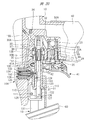
- FIG. 4 and 5 show the operation of the pin driving unit 70 when the trigger 41 is kept on while the push lever 13 is off. That is, in order to perform a continuous driving operation, the waiting time from when the trigger 41 is switched from OFF to ON until the push lever 13 is switched from OFF to ON and the driving machine 100 performs the first driving operation is reduced. It corresponds to the course. That is, when the waiting time exceeds a predetermined time and the pin driving unit 70 is in the state shown in FIG. 5, even if the push lever 13 is switched from OFF to ON, the lock pin locking unit 36 is locked to the pin 71 and pushed. Switching the lever 13 from off to on is restricted.
- the moving speed at which the pin 71 stopped at the initial position moves toward the restriction position is slow. For this reason, the pin 71 stops at the initial position as in FIG. 2 within a predetermined time from when the trigger 41 is turned on. Therefore, immediately after the trigger 41 is switched from off to on, the push lever 13 can be switched from off to on, and the driving machine 100 can perform the driving operation.
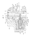
- FIG. 6 shows the state of the pin drive unit 70 when the push lever 13 is to be switched from OFF to ON while the pin 71 reaches the restriction position from the initial position.
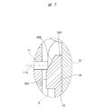
- FIG. 7 is an enlarged view of a region A surrounded by a broken line in FIG.
- the tip end portion 711 of the pin 71 contacts the inclined surface 36 ⁇ / b> B.
- a component force in the direction of the axis 114 is applied to the pin 71 from the inclined surface 36 ⁇ / b> B.
- the pin 71 can be moved to the left along the axis 114.
- the compressed air in the second air chamber 70B flows into the first air chamber 70A via the small hole 76A and the passage 119.
- the left cylindrical force is applied to the pin 71 from the outer cylinder member 35 without reducing the pressure of the first air chamber 70 ⁇ / b> A.
- the compressed air in the second air chamber 70B can be discharged to the first air chamber 70A, and the pin 71 can be moved leftward.
- the compressed air in the first air chamber 70A is discharged to the outside of the main housing 10 through the pressure chamber 30A, or a leftward force is applied to the pin 71 in FIG. Can be moved toward the initial position.
- the check valve 73A opens the passage 119, the moving speed at which the pin 71 shown in FIG. 3C moves to the left is larger than the moving speed at which the pin 71 shown in FIG. 3A moves to the right. can do.
- FIG. 8 shows a state where the push lever 13 shown in FIG. 6 is further raised.
- FIG. 9 shows a contact state between the pin 71 and the outer cylinder member 35 when the push lever 13 shown in FIG. 6 is further raised.
- the pin 71 shown in FIG. 9 is in contact with the vertical surface 36C below the inclined surface 36B, and can push up the push lever 13 so that the pin 71 slides on the vertical surface 36C. State. At this time, the pin 71 moves to the initial position in FIG. 3A.
- the push lever is moved after a predetermined time has elapsed from the time when only the trigger 41 is turned on and the pin 71 moves from the initial position to the restricted position. 13 cannot be switched from off to on.
- the push lever 13 when the push lever 13 is pressed against the driven material 81 within a predetermined time from when the trigger 41 is turned on, for example, before the pin 71 reaches the restriction position, as shown in FIG. And the lock pin engaging portion 36 come into contact with each other, but the pin 71 can be moved to the left as in FIG. 3D to switch the push lever 13 from OFF to ON. That is, in the continuous driving operation, if the waiting time after turning on the trigger 41 exceeds a predetermined time, the driving machine 100 cannot start the first driving operation. On the other hand, if the waiting time is within a predetermined time in the continuous driving operation, the driving machine 100 can start the first driving operation.
- the pin 71 shown in FIG. 8 is stopped at the initial position similarly to the pin 71 shown in FIG. 3A. Even if the push lever 13 is once switched from on to off from the state where the pin 71 is stopped at the initial position as shown in FIG. 8, if the trigger 41 is maintained in the on state, With the compressed air, the pin 71 gradually moves from the initial position in FIG. 3A toward the restriction position in FIG. 3C. The operation of the pin 71 is the same as the operation of the pin 71 when the trigger 41 is turned on from the state where both the trigger 41 and the push lever 13 are turned off.
- the pin 71 is changed from the state of FIG. 3A until the push lever 13 is once again turned off to on after the push lever 13 in the on state is once turned off as shown in FIG. It changes to the state of 3C. That is, when the waiting time from when the push lever 13 is once turned off until the push lever 13 is turned on again is within a predetermined time, the push lever 13 can be switched from off to on again. . On the other hand, if the waiting time from when the push lever 13 is once turned off until the push lever 13 is turned on again exceeds a predetermined time, the pin 71 turns the push lever 13 from off to on. To switch to.
- FIG. 10 shows a situation when the trigger 41 is turned off from the state of FIG. 5 where the push lever 13 cannot be turned on from off.
- the supply of the compressed air to the pressure chamber 30A is stopped, and at the same time, the pressure chamber 30A is opened to the atmosphere via the trigger valve chamber 20A.
- the first air chamber 70A is also released to the atmosphere, the pin 71 moves leftward, and returns to the initial position of FIG. 3A. That is, since both the push lever 13 and the trigger 41 are off, a single shot operation can be performed by turning on the push lever 13 again, and a continuous shot operation is performed again by turning on the trigger 41. Can be made.
- the time required for the pin 71 to move from the initial position to the restricting position can be significantly longer than the time required for the pin 71 to move from the restricting position to the initial position. For this reason, it is possible to suppress the push lever 13 from being turned off to on only when the waiting time in the continuous hitting operation is long, and to enable the push lever 13 from being turned off to on when the waiting time is short. Continuous hitting operation can be performed. At this time, the state where the push lever 13 cannot be turned on can be released in a short time by turning off the trigger 41, and thereafter, either the continuous hitting operation or the single shot hitting operation can be performed. .
- the trigger 41 is turned on when the driving machine 100 performs the first driving operation.
- the operation of turning the push lever 13 from OFF to ON is allowed before the elapse of the first time T1 from the time point.
- the pin 71 restricts switching of the push lever 13 from OFF to ON.
- the first time T1 is the time from when the pin 71 is at the initial position shown in FIG. 3A to when the pin 71 moves to the restriction position shown in FIG. 3C.
- FIG. 8 shows the state of the push lever 13 and the pin driving unit 70 when the driving machine 100 performs the driving operation by switching the push lever 13 from OFF to ON before the first time T1 has elapsed. Show.
- the pin 71 is temporarily turned off when the push lever 13 is turned off once for the next driving operation. After moving to the state, the operation when the driving machine 100 performs the driving operation after that is the same as the case where the driving machine 100 performs the first driving operation.
- the operation of turning the push lever 13 from the off state to the on state is allowed before the first time T1 elapses from the time point when the push lever 13 is turned off.
- the pin 71 regulates the operation of turning the push lever 13 from OFF to ON. Therefore, the first time T1 is preferably in the range of 1 second to 30 seconds, and particularly preferably in the range of 2 seconds to 20 seconds. More preferably, the first time T1 is preferably 3 seconds or longer and 10 seconds or shorter.
- the state of the pin 71 when the push lever 13 is once turned off from the state of FIG. 8 does not have to be exactly the same at the position of FIG. 3A and the position of FIG.
- the position of the pin 71 in FIG. 3A can be set to the right with respect to the position of the pin 71 in FIG.
- the driving machine 100 performs the second and subsequent driving operations
- the position is closer to the restriction position than the position when starting the operation.
- the time-out time when the driving device 100 performs the second and subsequent driving operations is shorter than the time-out time when the driving device 100 performs the first driving operation.
- the pin 71 restricts the push lever 13 from switching from OFF to ON, the trigger 41 is turned OFF, and after the second time T2 has elapsed since the trigger 41 is turned ON again, the pin 71 is The push lever 13 is allowed to be switched from off to on.
- the second time T2 is preferably short, and is preferably at least shorter than the above-described timeout time, that is, the first time T1. If the second time T2 is too long, it takes a long time for the restriction by the pin 71 to be released, so that an efficient operation using the driving machine 100 becomes difficult. For this reason, the second time T2 is preferably set to a range of 1 second or less, particularly 0.5 seconds or less.
- the first time T1 and the second time T2 are the moving speed at which the pin 71 moves rightward in FIGS. 3A and 3B, the moving speed at which the pin 71 moves leftward in FIGS. 3C and 3D, and the lock pin function. It can be adjusted by the shape of the stopper 36, that is, the angle of the lock pin engaging surface 36A and the inclined surface 36B. Among these, the moving speed and moving speed of the pin 71 are adjusted by the air flow amount in the small hole 76A in FIGS. 3A, 3B, 3C and 3D, the air flow amount in the passage 119, and the characteristics of the spring 77. be able to. The amount of air flow in the small hole 76A can be adjusted by setting the opening area of the small hole 76A. The amount of air flow in the passage 119 can be adjusted by the opening area of the passage 119.
- the pin driving unit 70 operates the pin 71 as described above when the trigger 41 and the push lever 13 are operated using only the compressed air used for the driving operation of the driving machine 100. be able to. For this reason, a sensor, an actuator, a motor, or the like used only for operating the pin 71 is unnecessary, and the driving machine 100 can be made inexpensive.
- the compressed air supplied from the trigger valve 20 side to the pressure chamber 30 ⁇ / b> A is used to drive the pin 71.
- a configuration other than the above-described configuration is also possible as a configuration for supplying compressed air to the striking unit according to the movement of the trigger and the push lever.
- the compressed air for driving the regulating member can be appropriately set according to the compressed air path in such a case.
- the pin 71 is in the initial state by the movement of the lock pin engaging portion 36 when performing control for the second and subsequent driving in the continuous driving operation.
- the pin 71 may be in the initial state by removing the compressed air from the first air chamber 70A after the driving device 100 has completed one driving operation.
- the restriction on the movement of the push lever 13 as described above is applied only to the first driving operation of the continuous driving operation, and is not applied to the second driving operation and thereafter. Also good.
- the guide member 91 supports the plunger guide 120.
- the plunger guide 120 has a cylindrical shape, and the push lever plunger 31 is movable in the direction of the axis 115 within the shaft hole 121 of the valve body 32 and the plunger guide 120. Further, the push lever plunger 31 is rotatable with respect to the plunger guide 120 about the axis 115.
- An elastic member 122 is disposed between the hook 110 and the plunger guide 120.
- the elastic member 122 is, for example, a metal compression spring. The elastic member 122 biases the push lever 13 downward in FIG.
- the push lever plunger 31 has a groove 123.
- the groove 123 is provided in a predetermined range in the direction of the axis 115 as shown in FIG.
- An urging member 124 is provided in the shaft hole 121, and the urging member 124 is, for example, a metal compression spring. A part of the urging member 124 is disposed in the groove 123, and the urging member 124 is pressed against the push lever plunger 31.
- the biasing member 124 applies a biasing force in the circumferential direction about the axis 115 to the push lever plunger 31.
- FIG. 12 shows a structure in which the biasing member 124 applies a clockwise biasing force to the push lever plunger 31 as an example.
- a groove 139 is provided on the outer peripheral surface of the push lever plunger 31. The groove 139 is provided with a predetermined length in the direction of the axis 115.
- the contact protrusion 125 is provided at the end closest to the push lever arm 131 in the longitudinal direction of the push lever 13.
- One contact protrusion 125 is provided in the circumferential direction around the axis 115 or a plurality, for example, two are provided at intervals.
- a block 127 is fixed to the hook 110, and the block 127 has a contact protrusion 126.
- One, or a plurality of, for example, two contact protrusions 126 are provided in the circumferential direction around the axis 115.
- the two contact protrusions 125 and the two contact protrusions are disposed on the same circumference.
- a pin driving portion 128 is provided on a wall portion 155 that forms the return chamber 10 ⁇ / b> A of the main housing 10.
- the pin driving unit 128 includes an outer cylinder member 129, an inner cylinder member 130, and a pin 152.
- the outer cylinder member 129 and the inner cylinder member 130 are provided around the axis 114.
- the axis 114 intersects with the axis 115, for example, at a right angle.
- a passage 132 that penetrates the outer cylinder member 129 in the radial direction is provided.
- the outer cylinder member 129 has a wall portion 149 that protrudes inward in the radial direction.
- the wall portion 149 is provided at a location closest to the plunger guide 120 in the direction of the axis 134.
- An axial hole 133 that penetrates the wall portion 149 in the direction of the axis 134 is provided.
- the shaft hole 133 is provided around the axis 134.
- the inner cylinder member 130 is provided in the outer cylinder member 129 and is provided so as not to move in the direction of the axis 134.
- a passage 135 is provided between the outer cylinder member 129 and the inner cylinder member 130, and the passage 132 connects the passage 135 and the control flow path 10C.
- the inner cylinder member 130 includes a cylinder part 136 and a wall part 137 in which one end part in the longitudinal direction of the cylinder part 136 is closed.
- a shaft hole 138 that penetrates the plunger guide 120 in and out is provided.
- the pin 152 has a large diameter part 147, a small diameter part 148, and a land part 140.
- the outer diameter of the large diameter portion 147 is larger than the outer diameter of the small diameter portion 148.
- a step portion 153 is provided at the boundary between the large diameter portion 147 and the small diameter portion 148.
- the step portion 153 is perpendicular to the axis 134 and is an annular plane.
- the large diameter portion 147 is disposed in the cylindrical portion 136, and the small diameter portion 148 is disposed over the shaft holes 133 and 138.
- the pin 152 is movable in the direction of the axis 134.
- the land portion 140 protrudes in the radial direction from the outer peripheral surface of the large diameter portion 147 and is provided in an annular shape.
- a seal member 141 is attached to the outer peripheral surface of the land portion 140.
- an air chamber 142 is provided between the land portion 140 and the outer cylinder member 129.
- the seal member 141 seals the air chamber 142.
- a seal member 150 is attached to the inner surface of the shaft hole 133 in the wall portion 149, and the seal member 150 seals the air chamber 142.
- a passage 143 that penetrates the cylindrical portion 136 in the radial direction is provided, and the passage 143 connects the passage 135 and the air chamber 142.
- the opening area of the passage 143 is narrower than the opening area of the passage 132.
- a passage 144 that penetrates the cylindrical portion 136 in the radial direction is provided, and a check valve 145 that opens and closes the passage 144 is provided.
- the check valve 145 allows air in the air chamber 142 to flow into the passage 135 via the passage 144.
- the check valve 145 prevents the air in the passage 135 from flowing into the air chamber 142 via the passage 144.
- the opening area of the passage 144 is wider than the opening area of the passage 143.
- an elastic member 146 is provided between the wall portion 137 and the land portion 140.
- the elastic member 146 urges the pin 152 in the right direction along the axis 134 in FIG. 14, that is, in a direction approaching the plunger guide 120.
- Specific example 2 of the restriction mechanism 154 includes a pin drive unit 128, a push lever plunger 31, an urging member 124, and a block 127.
- the trigger valve 20 When the compressed air is supplied to the pressure accumulating chamber 50A and the operating force is not applied to the trigger 41 as shown in FIG. 11, the trigger valve 20 is off, that is, closed.
- the push lever 13 When the push lever 13 is away from the workpiece 81, the push lever valve 30 is off, that is, in the closed state.
- the push lever 13 is pushed by the urging force of the elastic member 122, the hook 110 is engaged with the stopper 111, and the push lever 13 is stopped at the initial position.
- the action of the trigger valve 20 being closed is the same as in FIG.
- the push lever plunger 31 is biased by a biasing member 124 as shown in the upper part of FIG.
- the pin 152 is stopped at the initial position, the small diameter portion 148 of the pin 152 is positioned in the groove 139 and the pin 152 is pressed against the push lever plunger 31 as shown in the upper part of FIG. For this reason, the push lever plunger 31 is stopped at the first position P1 in the circumferential direction.
- the first position P1 will be described with reference to a location where the biasing member 124 is in contact with the push lever plunger 31.
- the contact protrusion 125 and the contact protrusion 126 are at the same position in the circumferential direction of the push lever plunger 31, as shown in the upper part of FIG. Further, as shown in the upper part of FIG. 16, the contact protrusion 125 and the contact protrusion 126 are in contact with each other.
- the trigger valve 20 when the operator applies an operating force to the trigger 41 in a state where the trigger 41 is turned off and the push lever 13 is turned off, the trigger valve 20 is switched from off to on.
- the trigger valve 20 is switched from OFF to ON, the compressed air in the pressure accumulating chamber 50A is sent to the trigger valve chamber 20A, the pressure chamber 30A, the control channel 10C, and the passages 132 and 135.
- the air sent to the passage 135 gradually flows into the air chamber 142 via the passage 143, and the pressure of the air chamber 142 increases.
- the pressure of the air chamber 142 applies an urging force opposite to the urging force of the elastic member 146 to the pin 152. That is, the pin 152 receives a leftward force in FIG. 14, that is, a force away from the push lever plunger 31 due to the pressure of the air chamber 142.
- the push lever plunger 31 is stopped at the first position P1 shown in the upper part of FIG. 12, or the angle at which the push lever plunger 31 moves in the circumferential direction from the first position P1 is lower in FIG. Is less than a predetermined angle ⁇ 1. For this reason, in the circumferential direction of the push lever plunger 31, the position of the contact protrusion 125 and the position of the contact protrusion 126 overlap at least partially as shown in the upper part of FIG.
- the push lever plunger 31 shown in FIG. 11 moves up along the axis 115.
- the small diameter portion 148 of the pin 152 slides in the groove 139.
- the push lever plunger 31 is pressed against the valve member 33 after the push lever plunger 31 blocks the exhaust passage 151 and the push lever valve chamber 30B.
- the valve member 33 is lifted along the axis 115 as shown in FIG. 17 by the moving force of the push lever plunger 31, and the push lever valve 30 is turned on, that is, the push lever valve 30 is opened as shown in FIG.
- the compressed air is sent to the driving channel 10B through the pressure chamber 30A and the push lever valve chamber 30B. Therefore, in the driving machine 100 shown in FIG. 1, the hitting unit 16 performs a driving operation.
- the compressed air in the passage 135 flows through the passage 132 and the control passage 10C to the pressure chamber 30A, and the pressure in the passage 135 decreases. To do.
- the check valve 145 opens and the compressed air in the air chamber 142 is discharged to the passage 135 through the passage 144. For this reason, the pressure of the air chamber 142 decreases, the pin 152 moves by the urging force of the elastic member 146, and the pin 152 stops at the initial position.
- the push lever 13 After the hitting portion 16 performs the driving operation, when the operator keeps the trigger 41 on and releases the push lever 13 from the driven material 81, the push lever 13 is urged by the urging force of the elastic member 122 as shown in FIG.
- the push lever plunger 31 opens the exhaust passage 151. For this reason, the compressed air in the driving flow path 10 ⁇ / b> B passes through the push lever valve chamber 30 ⁇ / b> B and the exhaust passage 151 and is discharged to the outside of the main housing 10. Further, when the hook 110 is engaged with the stopper 111, the push lever 13 stops at the initial position.
- the push lever plunger 31 While the movement amount of the pin 152 is less than the predetermined amount, the push lever plunger 31 is urged clockwise from the urging member 124 as shown in FIG. For this reason, the angle at which the push lever plunger 31 operates in the circumferential direction is increasing. And if the moving amount
- the predetermined angle ⁇ 1 is 45 degrees as an example.
- the operator presses the push lever 13 against the workpiece 81 after a predetermined time has elapsed from when the trigger 41 is switched from off to on, and the push lever 13 resists the force of the elastic member 122. 11, the contact protrusion 126 does not contact the push lever plunger 31 and the contact protrusion 125 does not contact the block 127 even when moved upward in FIG. 11. For this reason, the moving force of the push lever 13 is not transmitted to the push lever plunger 31.
- the push lever 13 moves downward in FIG. 17 by the urging force of the elastic member 122, and the push lever plunger 31 opens the exhaust passage 151. Further, the push lever 13 stops when the hook 110 is engaged with the stopper 111.
- the push lever 13 is driven into the target material within a predetermined time from when the trigger valve 20 is switched from off to on.
- the restriction mechanism 154 allows the push lever valve 30 to switch from OFF to ON, and the striking portion 16 performs a driving operation.
- the push lever 13 is not covered after a predetermined time from when the trigger valve 20 is switched from off to on.
- the restricting mechanism 154 restricts the push lever valve 30 from switching from OFF to ON, and the striking portion 16 does not perform the driving operation.
- the restriction mechanism 154 releasing the restriction applied to the push lever valve 30 will be described.
- the restricting mechanism 154 restricts the push lever valve 30 from switching from off to on
- the trigger valve 20 is switched from on to off.
- the compressed air in the pressure chamber 30A is discharged to the outside of the main housing 10 through the trigger valve chamber 20A and the shaft hole 95, and the pressure in the pressure chamber 30A decreases.
- the check valve 145 opens, and the compressed air in the air chamber 142 flows into the pressure chamber 30A through the passage 144, the passage 135, the passage 132, and the control flow passage 10C.
- the pressure drops.
- the pin 152 moves in a direction approaching the push lever plunger 31 in FIG. 19 by the biasing force of the elastic member 146. Then, a counterclockwise turning force is applied from the pin 152 to the push lever plunger 31 in the lower stage of FIG.
- the push lever plunger 31 operates counterclockwise at the lower stage of FIG. 12 against the urging force of the urging member 124, and returns to the first position P1 shown at the upper stage of FIG. 12 and stops.
- the relative position between the contact protrusion 125 and the contact protrusion 126 is in the state shown in the upper part of FIG. Therefore, the restriction applied to the push lever valve 30 by the restriction mechanism 154 is released. That is, when the push lever 13 is pressed against the driven material 81, the moving force of the push lever 13 is transmitted to the valve member 33 via the push lever plunger 31, and the push lever valve 30 can be switched from OFF to ON. .
- the operation speed when the pin 152 moves away from the wall portion 137 by the urging force of the elastic member 146 for a predetermined time is determined according to the opening area of the passage 143 and the spring constant of the elastic member 146.
- the restriction mechanism 154 includes a pin driving unit 70, a first plunger 161, a second plunger 156, and elastic members 157, 158, 159.
- the configuration of the pin driver 70 is the same as the configuration of the pin driver 70 shown in FIGS. 3A, 3B, 3C, and 3D.
- the first plunger 161 is fixed to the push lever 13.
- the second plunger 156 is disposed between the first plunger 161 and the valve member 33 in the direction of the axis 115. Both the first plunger 161 and the second plunger 156 are arranged concentrically around the axis 115. A part of the first plunger 161 is disposed in the shaft hole 121, and the first plunger 161 is movable in the direction of the axis 115 in the shaft hole 121.
- the second plunger 156 is disposed over the shaft hole 121 and the valve body 32, and the second plunger 156 is movable in the direction of the axis 115.
- the elastic member 157 is disposed between the push lever 13 and the plunger guide 120.
- the elastic member 157 is a metal compression spring, for example, and the elastic member 57 urges the push lever 13 downward in FIG.
- the elastic member 158 is disposed between the first plunger 161 and the second plunger 156.
- the elastic member 158 is, for example, a metal compression spring, and both ends of the elastic member 158 in the direction of the axis 115 are in contact with the first plunger 161 and the second plunger 156, respectively.
- the elastic member 159 is, for example, a metal compression spring, and both ends of the elastic member 159 in the direction of the axis 115 are in contact with the second plunger 156 and the valve member 33, respectively.
- the second plunger 156 has an annular engagement groove 160.
- a shaft hole 138 that penetrates the plunger guide 120 in the radial direction is provided, and when the pin 71 moves in the direction of the axis 114, the tip portion 711 enters and exits into the shaft hole 121 of the plunger guide 120 through the shaft hole 138. Is possible.
- the push lever 13 is separated from the workpiece 81, the push lever 13 is stopped at the initial position. For this reason, moving force is not transmitted from the first plunger 161 to the second plunger 156 from the push lever 13, and the second plunger 156 is stopped at the initial position.
- the urging force applied from the second plunger 156 to the valve member 33 is the minimum value. For this reason, the valve member 33 biased by the spring 34 is stopped in a state where the seal member 97 is pressed against the valve body 32. Therefore, the push lever valve 30 is off, that is, in a closed state.
- the second plunger 156 connects the push lever valve chamber 30 ⁇ / b> B and the exhaust passage 151. For this reason, the compressed air in the driving flow path 10 ⁇ / b> B is discharged to the outside of the main housing 10 through the push lever valve chamber 30 ⁇ / b> B and the exhaust passage 151.
- the trigger valve 20 When the operator applies an operating force to the trigger 41 in a state where the trigger valve 20 is turned off and the push lever valve 30 is turned off, the trigger valve 20 is switched from off to on.
- the trigger valve 20 When the trigger valve 20 is switched from OFF to ON, the compressed air in the pressure accumulating chamber 50A passes through the trigger valve chamber 20A, the pressure chamber 30A, the control flow channel 10C, the passage 118, the first air chamber 70A, and the small hole 76A. 2 Flows into the air chamber 70B. Then, the pressure in the second air chamber 70B gradually increases.
- the compressed air in the pressure accumulating chamber 50A passes through the trigger valve chamber 20A, the pressure chamber 30A, the control flow channel 10C, the passage 118, and the small hole 76A, and the second air chamber 70B.
- the pressure in the second air chamber 70B increases. For this reason, the pin 71 moves in the direction of the axis 114 in a direction approaching the second plunger 156 against the urging force of the spring 77.
- the trigger valve 20 is switched from OFF to ON within a predetermined time, the amount of movement of the pin 71 in the direction approaching the second plunger 156 from the initial position is less than the predetermined value, and the tip 711 is engaged. It does not enter the groove 160.
- the first plunger 161 resists the urging force of the elastic member 157. Then, it moves upward along the axis 115 in FIG. Then, the moving force of the first plunger 161 is transmitted to the second plunger 156 via the elastic member 158, and the second plunger 156 moves upward along the axis 115 in FIGS. For this reason, the second plunger 156 blocks the exhaust passage 151 and the push lever valve chamber 30B. Further, the moving force of the second plunger 156 is transmitted to the valve member 33 via the elastic member 159. As a result, the valve member 33 moves upward as shown in FIG. 23, and the push lever valve 30 is turned on, that is, opened.
- the striking unit 16 performs a driving operation.
- the compressed air in the passage 118 flows from the control channel 10C to the pressure chamber 30A, and the pressure in the passage 118 decreases.
- the check valve 73A opens, the compressed air in the second air chamber 70B is discharged to the passage 118, and the pressure in the second air chamber 70B decreases.
- the pin 71 moves in a direction away from the second plunger 156 by the biasing force of the spring 77, returns to the initial position, and stops. Further, the check valve 73A is closed.
- the second plunger 156 operates downward in FIG. 23 by the biasing force of the elastic member 159 to connect the push lever valve chamber 30B and the exhaust passage 151, and then stops at the initial position shown in FIG. Further, the valve member 33 operates downward in FIG. 23 by the biasing force of the spring 34, and the push lever valve 30 is turned off, that is, closed as shown in FIG.
- the tip portion 711 of the pin 71 passes through the shaft hole 138 and enters the shaft hole 121 of the plunger guide 120, and FIG. Stop at the restricted position as shown. That is, the tip 711 enters the engagement groove 160.
- the push lever 13 is driven into the target material within a predetermined time from when the trigger valve 20 is switched from off to on.
- the restriction mechanism 154 allows the push lever valve 30 to switch from OFF to ON, and the striking portion 16 performs a driving operation.
- the push lever 13 is not covered after a predetermined time from when the trigger valve 20 is switched from off to on.
- the restricting mechanism 154 restricts the push lever valve 30 from switching from OFF to ON, and the striking portion 16 does not perform the driving operation.
- the restriction mechanism 154 restricts the push lever valve 30 from switching from off to on, when the operator releases the operating force on the trigger 41, the trigger valve 20 is switched from on to off. Then, the compressed air in the pressure chamber 30A is discharged to the outside of the main housing 10 through the trigger valve chamber 20A and the shaft hole 95, and the pressure in the pressure chamber 30A decreases.
- the check valve 73A opens, and the compressed air in the second air chamber 70B flows into the pressure chamber 30A through the passage 119, the passage 118, and the control flow passage 10C.
- the pressure of 70B decreases.
- the pin 71 moves in a direction away from the push lever plunger 31 in FIGS. 25 and 26 by the biasing force of the spring 77.
- the tip 711 comes out of the shaft hole 138 as shown in FIG. Therefore, the restriction applied to the push lever valve 30 by the restriction mechanism 154 is released. That is, when the push lever 13 is pressed against the driven material 81 shown in FIG. 1, the moving force of the push lever 13 is transmitted to the valve member 33 via the first plunger 161 and the second plunger 156, and the push lever valve 30. Can be switched from off to on.
- the driving machine 200 shown in FIG. 27 includes a main housing 201, a handle 202, It has a nose 203, a cylinder 204, a striking part 205, a trigger valve 206, a push lever 207, a trigger 208 and a magazine 209.
- the main housing 201 is connected to the handle 202, and a pressure accumulating chamber 210 is formed across the main housing 201 and the handle 202.
- An air hose is attached to and detached from the handle 202, and compressed air is supplied from the air hose into the pressure accumulating chamber 210.
- the main housing 201 has a cylindrical shape, and the nose 203 has a cylindrical portion 239 and a flange 240.
- the flange 240 is provided at the end of the cylindrical portion 239 in the longitudinal direction.
- a nose 203 is fixed to the flange 240 at a first end 219 in the longitudinal direction of the main housing 201.
- An outer cylinder portion 211 and an inner cylinder portion 212 are provided on the inner surface of the second end portion 220 in the longitudinal direction of the main housing 201.
- the outer cylinder portion 211 and the inner cylinder portion 212 are provided around the axis 213.
- the longitudinal direction of the main housing 201 is a direction parallel to the axis 213.
- the axis 213 is the center of the cylinder 204.
- the outer cylinder part 211 is arranged outside the inner cylinder part 212, and the movable member 214 is arranged between the outer cylinder part 211 and the inner cylinder part 212.
- the movable member 214 is an annular body centered on the axis 213.
- a seal member 215 is provided between the movable member 214 and the outer cylinder portion 211, and a seal member 216 is provided between the movable member 214 and the inner cylinder portion 212.
- the movable member 214 is disposed between the cylinder 204 and the second end 220 in the direction of the axis 213.
- the movable member 214 is movable in parallel with the axis 213.
- a head valve 225 is attached to the movable member 214.
- the head valve 225 is annular, and is made of synthetic rubber as an example.
- the head valve 225 is movable in parallel with the axis 213 of the cylinder 204 together with the movable member 214.
- the head valve 225 can contact and separate from the end of the cylinder 204 in the direction of the axis 213.
- a head valve chamber 217 is provided between the outer cylinder portion 211, the inner cylinder portion 212, and the movable member 214.
- a biasing member 224 is disposed in the head valve chamber 217.
- the urging member 224 urges the movable member 214 in a direction along the axis 213 so as to approach the cylinder 204.
- the biasing member 224 is, for example, a metal compression spring.
- An air passage 218 connected to the head valve chamber 217 is provided in the main housing 201.
- a cover 221 is attached to the second end 220, and the cover 221 holds the bumper 222.
- the bumper 222 is disposed on the inner side of the inner cylindrical portion 212 and the inner side of the movable member 214 in the radial direction centering on the axis 213.
- the bumper 222 is a buffer member made of synthetic rubber as an example.
- An exhaust passage 223 is provided between the bumper 222 and the inner cylindrical portion 212 and between the cover 221 and the second end portion 220.
- the striking portion 205 includes a piston 226, a driver blade 227, and a piston upper chamber 229.
- the piston 226 is movable in the direction of the axis 213 in the cylinder 204, and the driver blade 227 is fixed to the piston 226.
- a seal member 228 is attached to the outer peripheral surface of the piston 226.
- a piston upper chamber 229 is formed between the piston 226 and the bumper 222 in the cylinder 204.
- a port 230 is formed between the bumper 222 and the movable member 214. When the movable member 214 moves in the direction of the axis 213, the movable member 214 and the bumper 222 come into contact with and separate from each other, and the port 230 is opened and closed. When the port 230 is opened, the piston upper chamber 229 and the exhaust passage 223 are connected, and when the port 230 is closed, the piston upper chamber 229 and the exhaust passage 223 are blocked.
- a port 231 is formed between the head valve 225 and the end of the cylinder 204.
- the head valve 225 operates in the direction of the axis 213, the head valve 225 and the cylinder 204 come into contact with and separate from each other, and the port 231 is opened and closed.
- the port 231 is opened, the pressure accumulation chamber 210 and the piston upper chamber 229 are connected.
- the port 231 is closed, the pressure accumulation chamber 210 and the piston upper chamber 229 are shut off.
- a bumper 232 is provided in the cylinder 204 at the end closest to the nose 203.
- the bumper 232 is a buffer member made of synthetic rubber as an example.
- the bumper 232 has a shaft hole 233.
- a wall portion 235 is provided on the inner surface of the main housing 201 and the connection portion of the handle 202.
- the wall portion 235 holds the holder 236.
- the holder 236 has an annular shape, and the holder 236 supports the cylinder 204 so as to be movable in the direction of the axis 213.
- the holder 236 positions the cylinder 204 in the radial direction.
- a piston lower chamber 234 is provided between the piston 226 and the bumper 232 in the cylinder 204.
- a partition wall 241 is provided outside the outer peripheral surface of the cylinder 204.
- the partition wall 241 is provided over the entire circumference of the cylinder 204.
- the partition wall 241 is provided between the holder 236 and the bumper 232 in the direction of the axis 213.
- a seal member 242 is attached to the outer peripheral surface of the partition wall 241. The seal member 242 contacts and seals the inner surface of the main housing 201 and the inner surface of the wall portion 235.
- a return chamber 237 is provided in the main housing 201.
- the return chamber 237 is provided between the main housing 201 and the wall portion 235 and the cylinder 204 and between the partition wall 241 and the first end portion 219.
- a passage 238 passing through the cylinder 204 in the radial direction is provided.
- a passage 238 connects the piston lower chamber 234 and the return chamber 237.
- a check valve 243 is provided in the return chamber 237. The check valve 243 allows the compressed air in the piston lower chamber 234 to flow into the return chamber 237 and prevents the compressed air in the return chamber 237 from flowing into the piston lower chamber 234.
- a passage 244 that penetrates the cylinder 204 in the radial direction is provided. The passage 244 connects the piston lower chamber 234 and the return chamber 237.
- a reset chamber 245 is provided between the cylinder 204 and the main housing 201 and the wall portion 235.
- the reset chamber 245 is provided between the holder 236 and the partition wall 241 in the direction of the axis 213.
- a passage 246 penetrating the cylinder 204 in the radial direction is provided.
- the passage 246 connects the piston lower chamber 234 and the reset chamber 245.
- a check valve 247 is provided in the reset chamber 245. The check valve 247 allows the compressed air in the piston lower chamber 234 to flow into the reset chamber 245 and prevents the compressed air in the reset chamber 245 from flowing into the piston lower chamber 234.
- the cylindrical portion 239 is disposed along the direction of the axis 213, and the cylindrical portion 239 has an injection path 248.
- the injection path 248 and the shaft hole 233 are arranged concentrically around the axis 213.
- the driver blade 227 is movable in the direction of the axis 213 within the shaft hole 233 and the injection path 248.
- the push lever 207 is attached to the cylinder portion 239 so as to be movable in the direction of the axis 213.
- the magazine 209 accommodates the nail 80.
- a plurality of nails 80 are connected to each other.
- the magazine 209 accommodates a plurality of nails 80 arranged in a spiral.
- the magazine 209 has a feed mechanism that feeds the nails 80 one by one to the injection path 248.
- a regulation mechanism 316 shown in FIG. 29 includes a timeout valve 315, a lock valve 293, and a holder 254.
- An arm 318 connected to the push lever 207 is provided, and a pin 253 is attached to the arm 318.
- the pin 253 can move in the direction of the axis 213 together with the push lever 207.
- a holder 254 is attached to the pin 253.
- the holder 254 has a cylindrical portion 255, and the holder 254 holds the plunger 256.
- the pin 253 holder 254 and the plunger 256 are operable in the direction of the axis 257.
- the axis 257 is parallel to the axis 213.
- the nose 203 has a support portion 305.
- a cylinder 258 is attached to the plunger 256.
- the cylinder 258 is movable in the direction of the axis 257 with respect to the plunger 256.
- the plunger 256 has a disc portion 259, and an elastic member 260 is provided between the disc portion 259 and the cylinder 258.
- the elastic member 260 is a metal compression spring as an example.
- the elastic member 260 generates a biasing force that separates the disk portion 259 and the cylinder 258 in the direction of the axis 257.
- a stopper 261 is provided on the wall 235, and the cylinder 258 biased by the elastic member 260 is fixed to the wall 235 by the stopper 261.
- the cylinder 258 has a cylindrical portion 262 and is provided with a shaft hole 263 that penetrates the cylindrical portion 262 in the radial direction.
- the plunger 256, the holder 254, and the pin 253 urged in the direction of the axis 257 by the elastic member 260 are stopped when the holder 254 contacts the support portion 305.
- the trigger 208 is supported so as to be rotatable about the support shaft 249 with respect to the main housing 201.
- a trigger arm 250 is attached to the trigger 208 so as to be rotatable about a support shaft 251.
- a biasing member 252 that biases the trigger arm 250 is provided.
- the biasing member 252 is a metal compression spring as an example. In FIG. 29, the urging member 252 urges the trigger arm 250 clockwise about the support shaft 251.
- the configuration of the trigger valve 206 will be described.
- the trigger valve 206 includes a trigger valve guide 264, a plunger guide 265, a valve member 266, and plungers 267 and 268.
- the wall 235 is provided with a recess 269, and the trigger valve guide 264 is provided in the recess 269.
- the trigger valve guide 264 has a cylindrical shape with the axis 270 as the center. The trigger valve guide 264 does not move in the direction of the axis 270 with respect to the wall 235. Further, the trigger valve guide 264 and the inner surface of the wall portion 235 are sealed with a seal member 271.
- the plunger guide 265 is provided inside the trigger valve guide 264.
- the plunger guide 265 does not move in the direction of the axis 270 with respect to the trigger valve guide 264.
- the plunger guide 265 has a cylindrical shape and has a shaft hole 273.
- a passage 274 parallel to the axis 270 is provided on the outer peripheral surface of the plunger guide 265. The passage 274 connects the inside 272 and the outside of the main housing 201.
- the plunger 267 is disposed in the shaft hole 273 and outside the main housing 201 and is movable in the direction of the axis 270.
- the end of the plunger 267 contacts the trigger arm 250.
- a seal member 312 is attached to the outer peripheral surface of the plunger 267.
- the valve member 266 is disposed in the trigger valve guide 264.
- the valve member 266 is movable in the direction of the axis 270 with respect to the trigger valve guide 264.
- a passage 275 is formed between the valve member 266 and the trigger valve guide 264.
- a passage 276 passing through the trigger valve guide 264 in the radial direction is provided, and the passage 276 connects the passage 275 and the air passage 218.
- Seal members 277 and 278 are attached to the outer peripheral surface of the valve member 266. When the seal member 277 is pressed against the inner surface of the trigger valve guide 264, the seal member 277 blocks the pressure accumulation chamber 210 and the passage 275. When the seal member 277 is separated from the inner surface of the trigger valve guide 264, the pressure accumulating chamber 210 and the passage 275 are connected.
- the seal member 314 When the seal member 314 is pressed against the inner surface of the trigger valve guide 264, the seal member 314 blocks the passage 276 and the passage 274. When the seal member 277 is separated from the inner surface of the trigger valve guide 264, the passage 276 and the passage 274 are connected.
- the plunger guide 265 has a recess 310, and a part of the plunger 268 in the longitudinal direction is disposed in the recess 310.
- the plungers 267 and 268 are arranged coaxially with respect to the axis 270 and in series.
- a part of the valve member 266 is disposed in the recess 310.
- a seal member 280 is attached to the outer peripheral surface of the valve member 266.
- the seal member 280 blocks the inside of the recess 310 and the inside 272.
- a spring 307 is provided between the plunger 268 and the valve member 266.
- the spring 307 is a metal compression spring as an example.
- the plunger 268 is pressed against the step portion 306 by the biasing force of the spring 307.
- the valve member 266 is biased in the direction away from the step portion 306 in the direction of the axis 270 by the biasing force of the spring 307.
- a seal member 308 is attached to the outer peripheral surface of the plunger 26. When the seal member 308 is separated from the valve member 266, the pressure accumulation chamber 210 is connected to the space 309 through the recess 310. When the seal member 308 comes into contact with the valve member 266, the pressure accumulating chamber 210 and the recess 310 are shut off.
- the recess 310 and the shaft hole 273 are connected, and a space 309 is formed between the plunger 268 and the plunger 267.
- a step portion 306 is provided at a location where the recess 310 and the shaft hole 273 are connected.
- the step portion 306 is an end surface perpendicular to the axis 270.
- a space 309 is provided between the plunger 267 and the plunger 268. The space 309 is connected to the recess 310.
- a timeout valve 315 is provided on the wall 235.
- the time-out valve 315 includes a valve member 319, a time-out valve chamber 279, and a spring 320 as shown in FIG.
- the timeout valve chamber 279 is connected to the reset chamber 245 through the passage 283.
- the valve member 319 has a large diameter portion 285 and a small diameter portion 286.
- the valve member 319 has timer passages 281 and 282.
- the timer passage 281 penetrates the small diameter portion 286 in the radial direction, and the timer passage 281 is connected to the timeout valve chamber 279.
- the opening area of the timer passage 281 is narrower than the opening area of the timer passage 282.
- a passage 290 is provided in the wall portion 235, and the timer passage 281 is connected to the passage 290.
- the passage 290 is connected to the space 309 as shown in FIG.
- An accommodating portion 287 is formed in the wall portion 235, and the valve member 319 is movable in the direction of the axis 288 within the accommodating portion 287.
- the time-out valve chamber 279 is disposed on the one end side of the valve member 319 in the direction of the axis 288 in the accommodating portion 287.
- a seal member 289 is attached to the outer peripheral surface of the large diameter portion 285.
- the seal member 289 seals between the passage 290 and the timeout valve chamber 279.
- a space 284 is formed between the inner surface of the accommodating portion 287 and the outer peripheral surface of the small diameter portion 286.
- the space 284 is connected to the passage 290 regardless of the position of the valve member 319 in the direction of the axis 288.
- a space 291 is formed between the inner surface of the accommodating portion 287 and the end surface of the small diameter portion 286.
- the space 291 is connected to the timer passage 281.
- a seal member 292 is attached to the outer peripheral surface of the small diameter portion 286.
- the spring 320 is a metal compression spring as an example. The spring 320 urges the valve member 319 in the direction of narrowing the space 291 in the direction of the axis 288.
- a lock valve 293 is provided on the wall portion 25.
- the lock valve 293 includes a storage chamber 294, a lock pin 295, and a spring 296.
- the lock pin 295 can move in the direction of the axis 301.
- the lock pin 295 has a large diameter portion 297 and a small diameter portion 298.
- the outer diameter of the large diameter portion 297 is larger than the outer diameter of the small diameter portion 298.
- a lock chamber 311 is formed between the large diameter portion 297 and the inner surface of the storage chamber 294.
- a passage 299 is provided in the wall portion 235, and the passage 299 connects the lock chamber 311 and the timeout valve chamber 279.
- a shaft hole 300 is provided in the wall portion 235, and the small-diameter portion 298 is disposed over the shaft hole 300 and the shaft hole 263.
- the small diameter portion 298 is movable in the direction of the axis 301 within the shaft hole 300 and the shaft hole 263.
- a seal member 302 is provided between the shaft hole 300 and the small diameter portion 298.
- a seal member 303 is provided on the outer peripheral surface of the large diameter portion 297. Seal members 302 and 303 seal the lock chamber 311.
- the spring 296 is, for example, a metal compression spring.
- the spring 296 urges the lock pin 295 in the direction of approaching the holder 254 in the direction of the axis 301.
- a passage 304 is provided in the wall 235.
- the passage 304 connects the space in the accommodation chamber 294 where the spring 296 is disposed and the outside of the main housing 10.
- the initial state of the driving machine 200 is a state in which the operator does not apply an operating force to the trigger 208 and the push lever 207 is separated from the driven material 81. It can be grasped as the trigger 208 being turned off that the operator does not apply operating force to the trigger 208.
- the state in which the push lever 207 is separated from the workpiece 81 can be grasped as the push lever 207 being turned off.
- the push lever 207 is restricted from moving in the direction away from the flange 240 in the direction of the axis 213. Further, since the small diameter portion 298 is located in the shaft hole 263, the cylinder 258 is prevented from moving in the direction of the axis 257.
- the valve member 319 is pressed by the urging force of the spring 28, the large diameter portion 285 is pressed against the wall portion 235, and the valve member 319 is stopped. Further, the seal member 292 is in contact with the inner surface of the wall portion 235. For this reason, the space 291, the passage 290, and the space 284 are blocked. Further, as shown in FIG. 32, the trigger arm 250 and the trigger 208 that receive the urging force of the urging member 252 are both stopped at the initial position in contact with the cylinder 258.
- the seal member 277 has a trigger valve guide away from 264. For this reason, the pressure accumulating chamber 210 and the passage 275 are connected. Further, the seal member 314 is pressed against the trigger valve guide 264. The seal member 314 blocks the passage 275 and the passage 274.
- the urging force of the urging member 224 is transmitted to the cylinder 204 via the movable member 214 and the head valve 225.
- the end of the cylinder 204 in the direction of the axis 213 is pressed against the flange 240, and the cylinder 204 is stopped.
- the port 231 is closed.
- the movable member 214 is away from the bumper 222 and the port 230 is open.
- the piston 226 contacts the bumper 222, and the hitting portion 205 stops at the top dead center.
- the compressed air in the pressure accumulating chamber 210 is converted into a space 313 between the valve member 266 and the plunger 268, It flows into the space 309 through the recess 310. Then, the plunger 267 is pressed against the trigger arm 250 by the pressure of the compressed air, and the space 309 and the passage 290 are connected.
- the element to which the operating force is transmitted is divided into two plungers 267 and 268. Therefore, in a state where compressed air is supplied to the pressure accumulating chamber 210, the trigger arm 250 is pushed downward in FIG. 32 by the pressure of the compressed air sent from the pressure accumulating chamber 210 to the space 309, and the trigger 208 contacts the cylinder 358. To stop at the initial position. Therefore, it is not necessary to provide a biasing member that biases the trigger 208 toward the cylinder 358 in order to hold the trigger 208 in the initial position.
- the state where the space 309 and the passage 290 are connected can be grasped as the trigger valve 206 being on.
- the compressed air in the space 309 flows into the timer passage 281 through the passage 290.
- the valve member 319 moves in a direction approaching the passage 299 against the biasing force of the spring 320.
- the space 284 is connected to the timer passage 282 through the space 291.
- the compressed air is supplied to the lock chamber 311 through the spaces 284, 291, the timer passage 282, the timeout valve chamber 279 and the passage 299.
- the large diameter portion 297 receives the pressure of the compressed air, and the lock pin 295 moves away from the holder 254 against the urging force of the spring 296. For this reason, the small diameter portion 298 moves out of the cylindrical portion 262. Accordingly, the push lever 207 can move in a direction approaching the flange 240 in FIG.
- the check valve 247 is closed by the pressure in the reset chamber 245.
- valve member 319 When the pressure in the passage 290 and the pressure in the passage 299 become the same, the valve member 319 operates in a direction away from the passage 299 by the biasing force of the spring 320, and the end surface of the large diameter portion 285 is a wall as shown in FIG. When contacting the part 235, the valve member 319 stops. Therefore, the seal member 292 blocks the space 284 and the space 291 from each other.
- the trigger 208 In a state where compressed air is supplied to the pressure accumulating chamber 210 and the push lever 207 is away from the driven material 81, when the operator applies an operating force to the trigger 208, the trigger 208 is supported as shown in FIG. It moves counterclockwise about the shaft 249, the trigger 208 moves away from the cylinder 258, and the trigger 208 comes into contact with the plunger guide 265 and stops.
- the trigger arm 250 is maintained in contact with the cylinder 258. It can be grasped as the trigger 208 being turned on that the operator applies operating force to the trigger 208.
- the plunger 267 operates in a direction approaching the plunger 268 with the rotational force of the trigger 208, and the seal member 312 blocks the space 309 and the passage 290.
- the passage 290 is connected to the outside of the main housing 201 through a gap between the plunger 267 and the plunger guide 265. Therefore, the compressed air in the lock chamber 311 passes through the passage 299, the timeout valve chamber 279, the timer passage 281, and the passage 290 and is gradually discharged to the outside of the main housing 201.
- the lock pin 295 starts to move toward the holder 254 by the biasing force of the spring 296.
- the time point when the pressure in the lock chamber 311 decreases and the lock pin 295 starts to operate with the urging force of the spring 296 is referred to as a reference time point.
- the small diameter portion 298 of the lock pin 295 does not reach the cylindrical portion 262.
- the push lever 207 is pressed against the workpiece 81 within a predetermined time from the reference time and the push lever 207 moves in the direction of the axis 213 toward the flange 240, the operating force of the push lever 207 is the pin 253. And transmitted to the plunger 256 via the holder 254.
- the plunger 256 operates in a direction approaching the plunger guide 265 in the direction of the axis 257 against the urging force of the elastic member 260.
- the trigger arm 250 operates clockwise about the support shaft 251 against the biasing force of the biasing member 252 by the operating force of the plunger 256.
- the plunger 267 is pressed against the plunger 268 by the operating force of the trigger arm 250 as shown in FIG. 36, and the plunger 268 moves in a direction away from the step portion 306.
- the seal member 308 blocks the pressure accumulation chamber 210 and the space 313.
- the pressure in the pressure accumulating chamber 210 increases, and the valve member 266 operates in a direction approaching the step portion 306 under the pressure in the pressure accumulating chamber 210.
- the seal member 277 is pressed against the trigger valve guide 264 and the pressure accumulating chamber 210 and the passage 275 are shut off.
- the seal member 314 is separated from the trigger valve guide 264, and the passage 275 and the passage 274 are connected. In this way, the head valve chamber 217 is connected to the outside of the main housing 201 via the air passage 218, the passage 276, the passage 275, and the passage 274.
- the head valve 225 receives the pressure in the pressure accumulating chamber 210, and the head valve 225 and the movable member 214 operate in a direction approaching the cover 221 in the direction of the axis 213 as shown in FIG. Then, the movable member 214 and the bumper 222 come into contact with each other, the port 230 is shut off, and the port 231 is opened. For this reason, the compressed air in the pressure accumulation chamber 210 flows into the piston upper chamber 229, and the pressure in the piston upper chamber 229 increases. Then, the hitting unit 205 starts a driving operation. That is, the hitting portion 205 is lowered so as to approach the bumper 232 in the direction of the axis 213, and the driver blade 227 drives the nail 80 in the injection path 248 into the driven material 81.
- the check valve 247 opens, and a part of the compressed air in the piston upper chamber 229 flows into the reset chamber 245.
- the compressed air that has flowed into the reset chamber 245 flows into the lock chamber 311 through the passage 283 and the passage 299.
- the pressure in the lock chamber 311 increases, and the lock pin 295 operates in a direction away from the holder 254 against the biasing force of the spring 296. That is, the lock pin 295 returns to the position before starting the operation at the reference time.
- the piston 226 collides with the bumper 232, the striking portion 205 reaches the bottom dead center, and the bumper 232 absorbs the impact.
- the push lever 207 is moved to the elastic member 260.
- the holder 254 and the plunger 256 move in the direction of the axis 257 in a direction away from the plunger guide 265 by the urging force of the elastic member 260.
- the push lever 207 stops at the initial position, and the plunger 256 also stops.
- the compressed air in the return chamber 237 flows into the piston lower chamber 234 through the passage 244. For this reason, the striking part 205 rises from the bottom dead center, the piston 226 contacts the bumper 222 and the head valve 225, and the striking part 205 stops at the top dead center.
- the hitting portion 205 is operated to sequentially drive the plurality of nails 80 into the driven material 81.
- the hitting unit 205 can perform the first driving operation, and the hitting unit 205 is the second and subsequent times. Can also be performed.
- the operation examples include a first operation example and a second operation example.
- the time point when the trigger valve 206 is switched from OFF to ON from the state where the push lever 207 is OFF and the trigger valve 206 is OFF is set as the reference time point.
- a time point at which the push lever 207 is switched from on to off from a state in which the push lever 207 is on and the trigger valve 206 is on is set as a reference time.
- the trigger valve 206 is on and the push lever 207 is off at the reference time.
- the compressed air in the lock chamber 331 passes through the gaps between the passages 299 and 290 and the plunger 267 and the plunger guide 265 and is discharged to the outside of the main housing 201. For this reason, the lock pin 295 operates in a direction approaching the holder 254 by the urging force of the spring 296. Then, when a predetermined time has elapsed from the reference time point, the small diameter portion 298 enters the cylindrical portion 262 as shown in FIGS.
- the holder 254 contacts the lock pin 295. For this reason, the moving force of the push lever 207 is not transmitted to the plunger 268, and the compressed air in the head valve chamber 217 is not discharged from the air passage 218 to the outside of the main housing 201. Therefore, the striking unit 205 does not perform the striking operation.
- the head valve chamber 217 has a function of preventing the driving operation of the hitting unit 205.
- the trigger valve 206 When the trigger 208 is turned off and the push lever 207 is turned off before or after the reference time exceeds the predetermined time, the trigger valve 206 is turned off, and the timeout valve 315 and the lock valve 293 are The state shown in FIG. 33 is obtained. That is, as shown in FIG. 30, the time-out valve 315 stops when the large-diameter portion 285 is pressed against the wall portion 235, and the seal member 292 blocks the space 284 and the space 291. That is, the pressure in the passage 290 and the passage 299 is the same.
- the speed at which the lock pin 295 operates in the direction approaching the holder 254 and the predetermined time are determined according to the spring constant of the spring 296 and the opening area of the timer passage 281.
- the regulation mechanism 316 shown in FIG. 38 includes a timeout valve 315, a lock valve 293, and a holder 254.
- the timeout valve 315 is the same as that shown in FIG.
- the lock valve 293 is the same as that shown in FIG.
- the spring 317 in which the spring 317 is interposed between the arm 318 and the support portion 305 is, for example, a metal compression spring.
- the spring 317 biases the push lever 207 shown in FIG. 27 upward in the direction of the axis 213, and the pin 253, the holder 254, and the plunger 256 approach the plunger guide 265 in FIG. Energize towards.
- the spring constant of the spring 317 is smaller than the spring constant of the biasing member 252.
- the elastic member 260 shown in FIG. 29 is not provided.
- Other configurations in FIGS. 38, 39, 40, 41, and 42 are the same as the configurations shown in FIGS. 27, 28, 29, 30, and 31.
- the operation and action when the restriction mechanism 316 of FIG. 38 is provided will be described.
- the initial state of the driving machine 200 is that compressed air is not supplied to the pressure accumulating chamber 210 shown in FIG. 27, the operator has separated the push lever 207 shown in FIG. This means that the user has not applied any operating force to the trigger 208.
- the urging force of the spring 317 is transmitted to the cylinder 258 via the disk portion 259, and the cylinder 258 comes into contact with the stopper 261 and stops.
- the trigger 208 comes into contact with the cylinder 258 and stops, and the trigger arm 250 comes into contact with the plunger 256 and stops.
- the small-diameter portion 298 of the lock pin 295 is located in the shaft hole 263 and is in contact with the outer peripheral surface of the holder 254 so that the lock pin 295 is stopped. That is, the lock pin 295 positions the cylinder 258 in the direction of the axis 270. Further, the recess 310 and the passage 290 are connected.
- the trigger arm 250 uses the support shaft 251 as a force point, uses the contact point between the plunger 267 and the trigger arm 250 as a fulcrum, and uses the contact point between the trigger arm 250 and the plunger 256 as an action point.
- the spring 317 contracts, and the plunger 256 moves toward the support portion 305 in the direction of the axis 270.
- the plunger 267 operates in a direction approaching the plunger 268, and the seal member 312 blocks the recess 310 and the passage 290.
- the plunger 268 does not move away from the step 306. Therefore, the trigger valve 206 is separated from the plunger guide 265 in the same manner as the trigger valve 206 shown in FIG. For this reason, the compressed air in the pressure accumulating chamber 210 is supplied to the head valve chamber 217 via the air passage 218, and the striking unit 205 does not perform the driving operation.
- the regulating mechanism 316 when the regulating mechanism 316 is in the state shown in FIG. 40, the operator is maintaining the state where the operator is applying the operating force to the trigger 208, and within a predetermined time from the reference time point, the small diameter portion of the lock pin 295 298 is located in the shaft hole 263 and does not reach the cylindrical portion 262. That is, the holder 254 can move in the direction away from the support portion 305 in the direction of the axis 270.
- the holder 254 and the plunger 256 are As shown at 41, it operates in the direction away from the support portion 305 in the direction of the axis 270. Then, the operating force of the trigger arm 250 is transmitted to the plunger 267 with the support shaft 251 as a fulcrum, the contact point between the plunger 256 and the trigger arm 250 as the force point, and the contact point between the trigger arm 250 and the plunger 267 as the action point.
- the seal member 277 blocks the pressure accumulating chamber 210 and the passage 276 as in the trigger valve 206 shown in FIG. Further, the seal member 314 is separated from the trigger valve guide 264, and the passage 276 and the passage 274 are connected. Therefore, the compressed air in the head valve chamber 217 is discharged to the outside of the main housing 201 through the air passage 218, the passage 276, and the passage 274. Accordingly, the striking unit 205 performs a driving machine operation, and the piston 226 collides with the bumper 232 as shown in FIG.
- the regulation mechanism 316 when the regulation mechanism 316 is in the state shown in FIG. 40, the state where the operator applies operating force to the trigger 208, and a predetermined time is exceeded from the reference time point, the state shown in FIG. As described above, the small diameter portion 298 of the lock pin 295 reaches the inside of the cylindrical portion 262. The small diameter portion 298 is located between the holder 254 and the stopper 261 in the direction of the axis 270.
- the lock pin 295 has the holder 254 and the plunger 256 in the direction away from the support portion 305 in the direction of the axis 270 in FIG. Prevent it from working.
- the speed at which the lock pin 295 approaches the holder 254 and the predetermined time are determined according to the opening area of the timer passage 281 and the spring constant of the spring 296, as in the fourth specific example of the restriction mechanism. .
- the operating force is first applied to the trigger 208, and then the push lever 207 is brought into contact with the driven material 81 to operate the hitting unit 205. It is an example.
- compressed air is supplied to the pressure accumulating chamber 210 in FIG. 27 to bring the regulating mechanism 316 into the state shown in FIG. 39, and the operator pushes the push lever 207 into the driven material 81. Then, an operating force is applied to the trigger 208.
- the reaction force when the push lever 207 is brought into contact with the driven material 81 is transmitted to the stopper 261 via the pin 253, the holder 254, the disk portion 259, and the cylinder 258. For this reason, the trigger 208 and the trigger arm 250 are held in a stopped state.
- the hitting unit 205 performs a driving operation as in FIG.
- the restriction mechanism 316 is in the state shown in FIG.
- a plurality of operations are performed.
- the nail 80 can be continuously driven into the workpiece 81, that is, a continuous driving operation can be performed.
- the driving machine 200 provided with the regulation mechanism 316 can also perform other operation examples.
- the operating force is first applied to the trigger 208, and thereafter
- the hitting unit 205 performs the driving operation.
- the operator applies an operating force to the trigger 208 first and then presses the push lever 207 against the workpiece 81
- the push is performed after a predetermined time from the reference time.
- the striking unit 205 does not perform the driving operation. Therefore, the same effect as in the first specific example can be obtained.
- the predetermined time is preferably longer than 1 second and shorter than 8 seconds.
- the predetermined time is preferably more than 2 seconds and less than 5 seconds.
- the predetermined time is preferably more than 2 seconds and less than 3 seconds.
- the driving machines 100 and 200 are examples of driving machines.
- the triggers 41 and 208 are examples of operation members.
- the push levers 13 and 207 are examples of contact members.
- the nail 80 is an example of a stopper member.
- the nail 80 includes those with a head and those without a head.
- the nail 80 includes an axial shape and an arch shape.
- the hitting units 16 and 205 are an example of a hitting unit.
- the piston upper chambers 84 and 229 are examples of the first pressure chamber.
- the cylinder valve chamber 101 is an example of a second pressure chamber.
- the ports 231 and 321 are an example of the first route.
- the cylinder 15 and the head valve 225 are an example of a valve body.
- the trigger valve 206 and the push lever valve 30 are examples of a control mechanism.
- the trigger valve 20 is an example of a first valve.
- the push lever valve 30 is an example of a second valve.
- the trigger valve 206 is an example of a third valve.
- the regulation mechanisms 154 and 316 are examples of regulation mechanisms.
- the pressure accumulating chambers 50A and 210 are an example of a pressure accumulating chamber.
- the pin driving units 70 and 128 and the lock valve 293 are examples of restriction valves.
- the outer cylinder member 35, the second plunger 156, the trigger arm 250, the plunger 256, and the disk portion 259 are examples of a transmission member.
- the second air chamber 70b, the air chamber 142, and the lock chamber 311 are examples of a restriction chamber.
- the pins 71 and 295 and the pin 152 are examples of pins.
- the plunger 268 is an example of a first plunger, and the plunger 267 is an example of a second plunger.
- the space 309 is an example of a space, and the space 309 can be grasped as a fourth pressure chamber.
- the cylinder 258 is an example of a support member.
- the initial positions of the pins 71, 295 and the pin 152 are examples of the permitted positions of the pins, and the restriction positions of the pins 71, 295 and the pin 152 are examples of the restriction positions of the pins.
- An example of the first function is that the pins 71 and 295 and the pin 152 stop at the initial positions.
- An example of the second function is that the pins 71, 295 and the pin 152 are in the restriction positions.
- the port 96 of the push lever valve 30 is opened, that is, the push lever valve 30 is in the first state.
- the port 96 is closed, that is, the push lever valve 30 is in the second state.
- the first state of the trigger valve 206 is that the seal member 277 of the trigger valve 206 contacts the trigger valve guide 264 to open the port 231.
- the second state of the trigger valve 206 is that the seal member 277 of the trigger valve 206 moves away from the trigger valve guide 264 and closes the port 231.
- the first pressure and the second pressure are the pressures of the compressed fluid applied to the valve body in the direction in which the valve body opens the first path.
- Compressed air is an example of a compressed fluid.
- an inert gas such as nitrogen gas or a rare gas can be used in addition to air.
- Regulating push lever operation, regulating push lever valve operation, regulating trigger valve operation, regulating plunger operation, regulating holder operation, pushing lever plunger operation Regulating is an example of prohibiting the operation of these elements or mechanisms.
- the driving machine is not limited to the above embodiment, and various changes can be made without departing from the scope of the driving machine.
- a lock pin or a pin that moves in a direction intersecting with the moving direction of the push lever 13 is used as a part of the regulating mechanism.
- the form and operation of the restricting member are arbitrary. Accordingly, the structure on the push lever side that is regulated by the regulating member is also set.
- compressed air is used for driving the striking part and the regulating member driving part.
- it is effective to provide a regulating mechanism that functions in the same manner as described above as long as the driving operation is controlled using a trigger and a push lever that are set to ON / OFF during the driving operation.
- the same power source that is, compressed air
- the power source of the striking unit and the power source of the restriction mechanism can be different.
- the driving source of the restricting member and the driving source of the striking unit are the same.
- the above-described configuration may be selectable only in the continuous hitting operation mode, and the configuration may not be operated in the single shot operation.
- the first pressure and the second pressure acting in the direction of opening the valve body may both be the same as the pressure in the pressure accumulation chamber, or both The pressure may be different.
- a nailing machine is described as an example of a driving machine.
- the driving machine of the embodiment is not limited to the nail driving machine as long as it has a trigger and a push lever and drives the stopper member into the driven material.
- the present invention can also be applied to a driving machine in which the hitting unit performs a driving operation on the screw and also applies a rotational force to the screw to tighten the screw.
Landscapes
- Physics & Mathematics (AREA)
- Fluid Mechanics (AREA)
- Engineering & Computer Science (AREA)
- Mechanical Engineering (AREA)
- Portable Nailing Machines And Staplers (AREA)
Abstract
L'objectif de la présente invention est d'empêcher qu'une position d'enfoncement, d'un élément d'arrêt par rapport à un matériau devant être entraîné, se décale. La machine d'enfoncement selon la présente invention comprend : un élément d'actionnement (41) ; un élément de contact ; une partie de frappe ; et une première chambre de pression, la machine d'enfoncement comprenant en outre : un élément de vanne pour ouvrir et fermer un premier passage à travers lequel un fluide comprimé est envoyé à la première chambre de pression ; un mécanisme de commande (30) ayant un premier état et un second état dans lesquels l'élément de vanne est commandé ; et un mécanisme de restriction (154) pour permettre et restreindre la commutation entre le premier état et le second état du mécanisme de commande (30). Le premier état est un état dans lequel le premier passage est ouvert par l'élément de vanne, et le second état est un état dans lequel le premier passage est fermé par l'élément de vanne. Le mécanisme de restriction (154) a une première fonction pour permettre au mécanisme de commande (30) d'être commuté du second état au premier état lorsque le point dans le temps actuel se situe dans un temps prédéterminé à partir d'un point dans le temps de référence, et une seconde fonction pour restreindre la commutation du mécanisme de commande (30) du second état au premier état lorsque le temps prédéterminé ou davantage de temps s'est écoulé depuis le point dans le temps de référence.
Priority Applications (4)
| Application Number | Priority Date | Filing Date | Title |
|---|---|---|---|
| JP2018553718A JP6677317B2 (ja) | 2016-11-30 | 2017-10-27 | 打込機 |
| DE112017006083.4T DE112017006083T5 (de) | 2016-11-30 | 2017-10-27 | Einschlagmaschine |
| US16/462,533 US11267116B2 (en) | 2016-11-30 | 2017-10-27 | Drive-in machine |
| CN201780070523.5A CN109952174B (zh) | 2016-11-30 | 2017-10-27 | 驱动机 |
Applications Claiming Priority (4)
| Application Number | Priority Date | Filing Date | Title |
|---|---|---|---|
| JP2016232705 | 2016-11-30 | ||
| JP2016-232705 | 2016-11-30 | ||
| JP2017191731 | 2017-09-29 | ||
| JP2017-191731 | 2017-09-29 |
Publications (1)
| Publication Number | Publication Date |
|---|---|
| WO2018100939A1 true WO2018100939A1 (fr) | 2018-06-07 |
Family
ID=62242673
Family Applications (1)
| Application Number | Title | Priority Date | Filing Date |
|---|---|---|---|
| PCT/JP2017/038895 WO2018100939A1 (fr) | 2016-11-30 | 2017-10-27 | Machine d'enfoncement |
Country Status (6)
| Country | Link |
|---|---|
| US (1) | US11267116B2 (fr) |
| JP (1) | JP6677317B2 (fr) |
| CN (1) | CN109952174B (fr) |
| DE (1) | DE112017006083T5 (fr) |
| TW (1) | TWI756304B (fr) |
| WO (1) | WO2018100939A1 (fr) |
Cited By (3)
| Publication number | Priority date | Publication date | Assignee | Title |
|---|---|---|---|---|
| TWI705876B (zh) * | 2019-03-13 | 2020-10-01 | 力肯實業股份有限公司 | 氣動釘槍的氣路結構 |
| TWI705877B (zh) * | 2019-05-21 | 2020-10-01 | 力肯實業股份有限公司 | 氣動釘槍單擊模式的自動復歸裝置 |
| US11065749B2 (en) | 2018-03-26 | 2021-07-20 | Tti (Macao Commercial Offshore) Limited | Powered fastener driver |
Families Citing this family (6)
| Publication number | Priority date | Publication date | Assignee | Title |
|---|---|---|---|---|
| JP6575679B2 (ja) * | 2016-04-28 | 2019-09-18 | 工機ホールディングス株式会社 | 打込機 |
| JP7114934B2 (ja) * | 2018-03-01 | 2022-08-09 | マックス株式会社 | 空気圧工具 |
| US11130221B2 (en) | 2019-01-31 | 2021-09-28 | Milwaukee Electric Tool Corporation | Powered fastener driver |
| TWI808135B (zh) * | 2019-03-06 | 2023-07-11 | 鑽全實業股份有限公司 | 電動釘槍 |
| EP3960376B1 (fr) | 2019-04-26 | 2024-02-14 | Max Co., Ltd. | Outil pneumatique |
| JP7435311B2 (ja) * | 2020-06-30 | 2024-02-21 | マックス株式会社 | 空気圧工具 |
Citations (7)
| Publication number | Priority date | Publication date | Assignee | Title |
|---|---|---|---|---|
| JPH0170980U (fr) * | 1987-10-30 | 1989-05-11 | ||
| JPH0261580U (fr) * | 1988-10-24 | 1990-05-08 | ||
| JPH0733575U (ja) * | 1993-12-06 | 1995-06-20 | マックス株式会社 | 可搬形電動ステープル打機 |
| JP2002254348A (ja) * | 2001-01-16 | 2002-09-10 | Illinois Tool Works Inc <Itw> | 空圧式締結具駆動工具 |
| US20140110452A1 (en) * | 2012-10-22 | 2014-04-24 | Illinois Tool Works Inc. | Fastener-driving tool including a reversion trigger |
| US20150034693A1 (en) * | 2013-08-02 | 2015-02-05 | Fasco S.R.L. | Safety Device For A Nailer |
| WO2016179081A1 (fr) * | 2015-05-06 | 2016-11-10 | Illinois Tool Works Inc. | Outil d'enfoncement avec dispositif de sécurité amélioré |
Family Cites Families (15)
| Publication number | Priority date | Publication date | Assignee | Title |
|---|---|---|---|---|
| US3612379A (en) * | 1965-05-24 | 1971-10-12 | Spotnails | Pneumatically operated fastener-driving machine |
| JPH0261580A (ja) | 1988-08-29 | 1990-03-01 | Nec Corp | レーダビデオ帯域圧縮装置 |
| JPH0270980A (ja) | 1988-09-06 | 1990-03-09 | Nippon Denso Co Ltd | 内燃機関のノッキング制御装置 |
| JPH0632308Y2 (ja) * | 1988-11-17 | 1994-08-24 | マックス株式会社 | 空気圧式釘打機 |
| JPH0733575A (ja) | 1993-07-14 | 1995-02-03 | Central Glass Co Ltd | 肥料被覆用組成物及び被覆粒状肥料及びその製造法 |
| US6186386B1 (en) * | 1999-08-06 | 2001-02-13 | Stanley Fastening Systems, Lp | Fastener driving device with enhanced depth adjusting assembly |
| US6371348B1 (en) * | 1999-08-06 | 2002-04-16 | Stanley Fastening Systems, Lp | Fastener driving device with enhanced sequential actuation |
| US6431429B1 (en) * | 1999-08-06 | 2002-08-13 | Stanley Fastening Systems, Lp | Fastener driving device with enhanced adjustable exhaust directing assembly |
| JP4135574B2 (ja) * | 2003-06-20 | 2008-08-20 | 日立工機株式会社 | 釘打機 |
| JP4102998B2 (ja) * | 2003-09-10 | 2008-06-18 | マックス株式会社 | 釘打機の起動装置 |
| CN102039580B (zh) * | 2009-10-21 | 2015-06-17 | 美克司株式会社 | 紧固件打入机 |
| JP5589804B2 (ja) | 2010-11-30 | 2014-09-17 | 日立工機株式会社 | 打込機 |
| DE102013106657A1 (de) * | 2013-06-25 | 2015-01-08 | Illinois Tool Works Inc. | Eintreibwerkzeug zum Eintreiben von Befestigungsmitteln in ein Werkstück |
| EP2826599A1 (fr) | 2013-07-16 | 2015-01-21 | HILTI Aktiengesellschaft | Procédé de commande et machine-outil manuelle |
| JP6090086B2 (ja) | 2013-09-27 | 2017-03-08 | 日立工機株式会社 | 打込機 |
-
2017
- 2017-10-27 WO PCT/JP2017/038895 patent/WO2018100939A1/fr active Application Filing
- 2017-10-27 US US16/462,533 patent/US11267116B2/en active Active
- 2017-10-27 DE DE112017006083.4T patent/DE112017006083T5/de not_active Withdrawn
- 2017-10-27 JP JP2018553718A patent/JP6677317B2/ja active Active
- 2017-10-27 CN CN201780070523.5A patent/CN109952174B/zh not_active Expired - Fee Related
- 2017-11-22 TW TW106140462A patent/TWI756304B/zh active
Patent Citations (7)
| Publication number | Priority date | Publication date | Assignee | Title |
|---|---|---|---|---|
| JPH0170980U (fr) * | 1987-10-30 | 1989-05-11 | ||
| JPH0261580U (fr) * | 1988-10-24 | 1990-05-08 | ||
| JPH0733575U (ja) * | 1993-12-06 | 1995-06-20 | マックス株式会社 | 可搬形電動ステープル打機 |
| JP2002254348A (ja) * | 2001-01-16 | 2002-09-10 | Illinois Tool Works Inc <Itw> | 空圧式締結具駆動工具 |
| US20140110452A1 (en) * | 2012-10-22 | 2014-04-24 | Illinois Tool Works Inc. | Fastener-driving tool including a reversion trigger |
| US20150034693A1 (en) * | 2013-08-02 | 2015-02-05 | Fasco S.R.L. | Safety Device For A Nailer |
| WO2016179081A1 (fr) * | 2015-05-06 | 2016-11-10 | Illinois Tool Works Inc. | Outil d'enfoncement avec dispositif de sécurité amélioré |
Cited By (4)
| Publication number | Priority date | Publication date | Assignee | Title |
|---|---|---|---|---|
| US11065749B2 (en) | 2018-03-26 | 2021-07-20 | Tti (Macao Commercial Offshore) Limited | Powered fastener driver |
| US11654538B2 (en) | 2018-03-26 | 2023-05-23 | Techtronic Power Tools Technology Limited | Powered fastener driver |
| TWI705876B (zh) * | 2019-03-13 | 2020-10-01 | 力肯實業股份有限公司 | 氣動釘槍的氣路結構 |
| TWI705877B (zh) * | 2019-05-21 | 2020-10-01 | 力肯實業股份有限公司 | 氣動釘槍單擊模式的自動復歸裝置 |
Also Published As
| Publication number | Publication date |
|---|---|
| US11267116B2 (en) | 2022-03-08 |
| JPWO2018100939A1 (ja) | 2019-06-27 |
| TWI756304B (zh) | 2022-03-01 |
| DE112017006083T5 (de) | 2019-08-08 |
| CN109952174A (zh) | 2019-06-28 |
| CN109952174B (zh) | 2022-05-03 |
| JP6677317B2 (ja) | 2020-04-08 |
| TW201821229A (zh) | 2018-06-16 |
| US20190344415A1 (en) | 2019-11-14 |
Similar Documents
| Publication | Publication Date | Title |
|---|---|---|
| WO2018100939A1 (fr) | Machine d'enfoncement | |
| CN108602179B (zh) | 打入机 | |
| JP5509770B2 (ja) | 空気打込機 | |
| US11331779B2 (en) | Driving machine | |
| CN109070322B (zh) | 打钉机 | |
| JP5509771B2 (ja) | 空気打込機 | |
| EP2274138B1 (fr) | Ensemble capuchon d'un outil d'enfoncement d'organe de fixation ayant un mécanisme de commutation incorporé dans celui-ci pour une commutation des modes de fonctionnement de l'outil d'enfoncement d'organe de fixation | |
| WO2016002540A1 (fr) | Machine d'enfoncement | |
| CN111372730A (zh) | 具有安全阀组件的气动钉枪 | |
| JP6634702B2 (ja) | 打込機 | |
| JP4752751B2 (ja) | 打込機 | |
| WO2013168719A1 (fr) | Outil d'entraînement | |
| CN111225769B (zh) | 具有安全调节元件的气动钉枪 | |
| JP6950424B2 (ja) | 打込み工具 | |
| TWI759578B (zh) | 釘打機 | |
| JP2004017206A (ja) | 圧縮空気駆動衝撃工具の起動バルブ機構 | |
| JP2020146821A (ja) | 打込機 | |
| JP7380818B2 (ja) | 空気圧工具 | |
| RU2800110C2 (ru) | Пневматический гвоздезабивной пистолет c предохранительным механизмом | |
| JP7205372B2 (ja) | 空気圧工具 | |
| JP2736840B2 (ja) | 空気圧式固定具打込機 | |
| RU2781824C2 (ru) | Пневматический гвоздезабивной пистолет с предохранительным клапанным блоком | |
| JP5741940B2 (ja) | 打込機 | |
| JP2016221618A (ja) | 打込機 | |
| AU2023285977A1 (en) | Fastener-driving tool with chamber member retaining assembly |
Legal Events
| Date | Code | Title | Description |
|---|---|---|---|
| 121 | Ep: the epo has been informed by wipo that ep was designated in this application |
Ref document number: 17876765 Country of ref document: EP Kind code of ref document: A1 |
|
| ENP | Entry into the national phase |
Ref document number: 2018553718 Country of ref document: JP Kind code of ref document: A |
|
| 122 | Ep: pct application non-entry in european phase |
Ref document number: 17876765 Country of ref document: EP Kind code of ref document: A1 |