WO2018100939A1 - 打込機 - Google Patents
打込機 Download PDFInfo
- Publication number
- WO2018100939A1 WO2018100939A1 PCT/JP2017/038895 JP2017038895W WO2018100939A1 WO 2018100939 A1 WO2018100939 A1 WO 2018100939A1 JP 2017038895 W JP2017038895 W JP 2017038895W WO 2018100939 A1 WO2018100939 A1 WO 2018100939A1
- Authority
- WO
- WIPO (PCT)
- Prior art keywords
- valve
- push lever
- chamber
- pressure
- trigger
- Prior art date
- Legal status (The legal status is an assumption and is not a legal conclusion. Google has not performed a legal analysis and makes no representation as to the accuracy of the status listed.)
- Ceased
Links
Images















Classifications
-
- B—PERFORMING OPERATIONS; TRANSPORTING
- B25—HAND TOOLS; PORTABLE POWER-DRIVEN TOOLS; MANIPULATORS
- B25C—HAND-HELD NAILING OR STAPLING TOOLS; MANUALLY OPERATED PORTABLE STAPLING TOOLS
- B25C1/00—Hand-held nailing tools; Nail feeding devices
- B25C1/04—Hand-held nailing tools; Nail feeding devices operated by fluid pressure, e.g. by air pressure
- B25C1/047—Mechanical details
-
- B—PERFORMING OPERATIONS; TRANSPORTING
- B25—HAND TOOLS; PORTABLE POWER-DRIVEN TOOLS; MANIPULATORS
- B25C—HAND-HELD NAILING OR STAPLING TOOLS; MANUALLY OPERATED PORTABLE STAPLING TOOLS
- B25C1/00—Hand-held nailing tools; Nail feeding devices
- B25C1/04—Hand-held nailing tools; Nail feeding devices operated by fluid pressure, e.g. by air pressure
- B25C1/041—Hand-held nailing tools; Nail feeding devices operated by fluid pressure, e.g. by air pressure with fixed main cylinder
- B25C1/043—Trigger valve and trigger mechanism
Definitions
- the present invention relates to a structure of a driving machine for driving a stopper member.
- the driving machine is used for driving a stopper member into a plate material as a material to be driven, for example, wood, gypsum board, steel plate or the like.
- the stopper member includes a nail, a screw, and the like as an example.
- the driving machine includes a nailing machine and a screw driving machine as an example.
- the nailing machine performs an operation of driving a nail into a material to be driven in one direction with a strong driving force.
- the screw driving machine is designed to drive the screw into the driven material in one direction and a distance shorter than the total length of the screw, rotate the screw driven into the driven material, and screw the screw into the driven material. Do.
- the structure of what uses compressed air as a power source of a driving machine is described in Patent Document 1, for example.
- the driving machine described in Patent Document 1 includes a main body, a handle, a nose, a cylinder, a piston, a push lever, a trigger, a pressure accumulation chamber, and a piston upper chamber.
- the cylinder and the piston upper chamber are provided in the main body.
- the piston can reciprocate within the cylinder.
- a driver blade is fixed to the piston.
- the handle is connected to the main body, and the nose is fixed to the main body.
- the pressure accumulating chamber is provided over the inside of the main body and the handle.
- the trigger is provided at a connection portion between the main body and the handle.
- the push lever is attached to the nose.
- the push lever is movable relative to the nose.
- the push lever is biased in a direction away from the main body by a spring. Then, when driving the stopper member into the plate member positioned below the push lever, the operator presses the tip of the push lever against the plate member with the nose facing down. By this operation, the push lever comes into contact with the plate material and moves in a direction approaching the main body along the nose.
- the trigger is provided at a connection portion between the main body and the handle portion, that is, a portion where the operator holds the handle portion. The trigger can rotate around the support shaft, and the trigger rotates when the operator operates the trigger.
- the driving machine starts driving operation when both the push lever is pressed against the plate material and the operator operates the trigger.
- an operator can drive a fastener member correctly to a desired location by operating a trigger.
- compressed air is supplied to the piston upper chamber by the operation of the trigger, and the driving machine starts driving operation.
- the operator presses the push lever against the plate material, and then the operator operates the trigger so that the driving machine performs driving, that is, the single driving operation is performed once for the stopper member. It is suitable for work that requires driving to be driven.
- the operator may perform the driving operation with the driving machine by bringing the push lever into contact with the plate material or the like while maintaining the state in which the trigger is operated in advance, that is, performing the continuous driving operation. it can.
- the driving machine starts driving operation.
- Such a continuous driving operation is suitable for a case where the stopper member is driven continuously at a plurality of locations in the plate material at short time intervals.
- the driving operation of the stopper member can be performed particularly efficiently. The worker selects whether to perform a single shot operation or a continuous shot operation according to the work content.
- An object of this invention is to provide the driving machine which can suppress driving a fastener member in the position shifted
- the driving machine is provided with an operation member operated by an operator, a contact member that comes into contact with the driven material, and an operation member.
- the driving member is driven into the driven material.
- a driving machine having a striking unit and a first pressure chamber that operates the striking unit with the pressure of a compressed fluid when the operation member is operated and the contact member comes into contact with the workpiece.
- a valve body operable to open and close a first path for sending the compressed fluid to the first pressure chamber, a control mechanism having a first state and a second state for controlling opening and closing of the valve body, and the control
- a restriction mechanism that permits and restricts switching between the first state and the second state of the mechanism, and the first state is that the operation member is operated and the contact member is When the contact with the driven material is established, the valve body
- the first path is opened, and the second state is that at least one of the operation member being operated and the contact member being in contact with the driven material is not established.
- the first path is closed by the valve body, and the restriction mechanism is predetermined from a reference time when both the operation member is operated and the contact member is separated from the driven material.
- the operation member When it is within the time, the operation member is operated with a first function that allows the contact member to contact the workpiece and the control mechanism to change from the second state to the first state. And when the contact member is in contact with the driven material when the contact member exceeds the predetermined time from the reference time when the contact member is separated from the driven material. Changes from the second state to the first state. And a, a second function of regulating the.
- the driving machine of one embodiment can suppress a shift of a position where the stopper member is driven into the driven material.
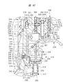
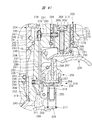
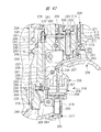
- FIG. 2 is an enlarged cross-sectional view showing a structural example of a trigger valve and a push lever valve in a state where both a trigger and a push lever are off in the driving machine shown in FIG. .
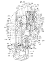
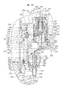
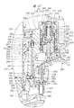
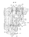
- FIG. 3 is a cross-sectional view illustrating a main part of a specific example 1 of the restriction mechanism illustrated in FIG. 2 in a state where a lock pin is in an initial position.
- FIG. 4 is a cross-sectional view illustrating a main part of the first specific example of the restriction mechanism illustrated in FIG.
- FIG. 4 is a cross-sectional view illustrating a main part of a specific example 1 of the restriction mechanism illustrated in FIG.
- FIG. 6 is a cross-sectional view illustrating a main part of the first specific example of the restriction mechanism illustrated in FIG. 2 in a state where the lock pin is moved from the restriction position toward the initial position.
- FIG. 3 is a cross-sectional view illustrating a state of the push lever valve after a short time has elapsed since the trigger valve, the push lever valve, and the restriction mechanism illustrated in FIG.
- FIG. 3 is a cross-sectional view illustrating a state of the push lever valve after a long time has elapsed since the trigger valve, the push lever valve, and the restriction mechanism illustrated in FIG.
- FIG. 3 is a specific example 1 of the trigger valve, the push lever valve, and the restriction mechanism shown in FIG.
- FIG. 3 is a specific example 1 of the trigger valve, the push lever valve, and the restriction mechanism shown in FIG. 2, and is a cross-sectional view illustrating a state in which the push lever is pushed up after a short time has elapsed since turning on only the trigger.
- region A in FIG. FIG. 3 is a specific example 1 of the trigger valve, the push lever valve, and the restriction mechanism shown in FIG. 2, and is a cross-sectional view illustrating a state in which the push lever is pushed up after a short time has elapsed since turning on only the trigger.
- FIG. 3 is a specific example 1 of the trigger valve, the push lever valve, and the restriction mechanism shown in FIG.
- FIG. 12 is a plan sectional view showing the operation of the restriction mechanism shown in FIG. 11. It is a perspective view of the contact protrusion provided in the push lever and block shown in FIG. It is an expanded sectional view which shows the principal part of FIG.
- FIG. 12 is a plan sectional view showing a relative position of a contact protrusion provided on the push lever and the block shown in FIG. 11.
- FIG. 4 is a specific example 2 of a restriction mechanism used in the driving machine of FIG. 1, and is a cross-sectional view of a main part in which a push lever is in an on state.
- FIG. 4 is a specific example 2 of a trigger valve, a push lever valve, and a restriction mechanism used in the driving machine of FIG.
- FIG. 4 is a specific example 2 of a restriction mechanism used in the driving machine of FIG. 1, and is a cross-sectional view of a main part in which a push lever is in an off state.
- FIG. 4 is a specific example 2 of a restriction mechanism used in the driving machine of FIG. 1, and is a cross-sectional view of a main part in which a push lever is in an off state.
- FIG. 5 is a specific example 2 of a trigger valve, a push lever valve, and a restriction mechanism used in the driving machine of FIG. 1, and is a cross-sectional view in a state where the trigger valve is turned on and the push lever valve is turned off.
- FIG. 4 is a specific example 3 of the trigger valve, push lever valve, and regulating mechanism used in the driving machine of FIG. It is sectional drawing which expands and shows the principal part of FIG.
- FIG. 6 is a specific example 3 of the trigger valve, push lever valve, and regulating mechanism used in the driving machine of FIG. 1, and is a cross-sectional view in a state where both the trigger valve and the push lever valve are on. It is sectional drawing which expands and shows the principal part of FIG. FIG.
- FIG. 4 is a specific example 3 of a trigger valve, a push lever valve, and a restriction mechanism used in the driving machine of FIG. 1, and is a cross-sectional view in a state where the trigger valve is on and the operation of the push lever valve is restricted. It is sectional drawing which expands and shows the principal part of FIG. It is sectional drawing which shows the whole driving machine which is Embodiment 2 in this invention.
- FIG. 28 is an enlarged cross-sectional view of a hitting portion shown in FIG. 27. It is a fragmentary sectional view which shows the specific example 4 of the control mechanism provided in the driving machine shown in FIG. It is an expanded sectional view of the timeout valve which the specific example 4 of a control mechanism has.
- FIG. 28 is a partial cross-sectional view of the driving machine shown in FIG. 27 in a state where compressed air is introduced.
- FIG. 28 is a partial cross-sectional view showing a state where compressed air is introduced into the driving machine shown in FIG. 27 and the lock valve is operated.
- FIG. 28 is a partial cross-sectional view of the driving machine shown in FIG. 27 with the trigger turned on.
- FIG. 28 is an overall cross-sectional view of the driving machine shown in FIG. 27 in a state where the hitting unit performs a hitting operation.
- FIG. 28 is a partial cross-sectional view of the driving machine shown in FIG.
- FIG. 28 is a partial cross-sectional view showing a state in which a predetermined time has passed since the trigger is turned on and the push lever is turned off in the driving machine shown in FIG. 27.
- FIG. 1 is a cross-sectional view showing a driving machine 100 corresponding to Embodiment 1.
- the driving machine 100 discloses a nailing machine as an example.
- the driving machine 100 drives a nail 80, which is an example of a stopper member, into a material 81 to be driven.
- FIG. 1 shows a cross-sectional view before the nail 80 is driven into the driven material 81.
- FIG. 1 is a cross-sectional view including an axis 82 of the driving machine 100 and is a view showing a part of the driving machine 100 as seen through.
- the driving machine 100 shown in FIG. 1 shows an example in which a nail 80 is driven in a vertical direction with respect to the driven material 81. For this reason, the axis 82 in FIG. 1 is arranged along the vertical direction.
- the vertical direction is the vertical direction in FIG.
- the driving machine 100 shown in FIG. 1 is an example in which a driving force downward in FIG. 1 is applied to the nail 80 and the nail 80 is driven into the driven
- the driving machine 100 includes a main housing 10, a handle 50, a nose 12, and a hitting unit 16.
- the main housing 10 has a substantially cylindrical shape extending in the vertical direction in FIG.
- the handle 50 is connected to the main housing 10 and protrudes outward in the radial direction of the main housing 10.
- the nose 12 is attached to the end of the main housing 10 in the longitudinal direction.
- the longitudinal direction of the main housing 10 and the direction of the axis line 82 are described as the vertical direction.
- the longitudinal direction of the main housing 10 is the same as the direction along the axis 82, the direction parallel to the axis 82, or the direction of the axis 82.
- the direction along the axis 82, the direction parallel to the axis 82, and the direction of the axis 82 are technically synonymous.
- the direction approaching the nose 12 is represented by any term of downward, downward, downward, and downward in this embodiment.
- the direction away from the nose 12 is represented by any term of upward, upward, upward, and upward in this embodiment.
- an air valve 51 is provided at an end portion of the handle 50 opposite to the end portion connected to the main housing 10.
- the air valve 51 is detachable from an air hose for supplying compressed air.
- the air hose is not shown.
- it may be described as the front-rear direction.
- separates from the air valve 51 among the front-back direction may be represented by the term in any one among the front, the front side, and the front.
- the direction which approaches the air valve 51 among front-back directions is represented by any term among back, back, and back. Note that, in FIG. 1 in which the driving machine 100 is viewed from the side, an imaginary line 83 and an axis 82 intersect each other.
- the striking portion 16 is provided inside the main housing 10.
- the striking portion 16 is a mechanism that applies a driving force to the nail 80 toward the lower side in FIG. 1 using compressed air.
- a cylinder 15 is provided in the main housing 10.
- the center line of the cylinder 15 is represented as an axis 82 in FIG.
- a pressure accumulation chamber 50 ⁇ / b> A is provided in the handle 50, the upper side of the cylinder 15, and the outer periphery of the cylinder 15.
- the compressed air supplied from the air hose is stored in the pressure accumulating chamber 50A.
- a known pressure reducing valve may be provided in the air path between the air valve 51 and the pressure accumulating chamber 50A. The pressure reducing valve adjusts the pressure of the compressed air using a differential pressure between the spring pressure and the air pressure. That is, the pressure of the compressed air supplied into the pressure accumulating chamber 50A can be adjusted.
- the piston 14 is provided in the cylinder 15, and the piston 14 can reciprocate in the direction of the axis 82 in the cylinder 15.
- An exhaust valve chamber 103 is provided above the cylinder 15 in the main housing 10.
- a piston upper chamber 84 is provided between the exhaust valve chamber 103 and the piston 14.
- the exhaust valve chamber 103 is connected to the cylinder valve chamber 101.
- An exhaust passage 85 is provided above the cylinder 15 in the main housing 10.
- a port 86 that connects the exhaust passage 85 and the piston upper chamber 84 is provided.
- An exhaust valve 102 is provided between the exhaust valve chamber 103 and the port 86. The exhaust valve 102 opens and closes the port 86.
- a bumper 89 is provided on the cylinder 15 in the main housing 10.
- the bumper 89 is a synthetic rubber as an example.
- a piston lower chamber 15 ⁇ / b> A is provided below the piston 14 in the cylinder 15.
- a return chamber 10 ⁇ / b> A is provided between the main housing 10 and the outer peripheral surface of the cylinder 15.
- the cylinder 15 has a check valve 90 for connecting and blocking the piston lower chamber 15A and the return chamber 10A.
- a bumper 87 is provided between the cylinder 15 and the nose 12.
- the bumper 87 is a buffer member made of synthetic rubber.
- a return elastic member 88 is provided in the main housing 10, and the elastic member 88 biases the cylinder 15 upward.
- the elastic member 88 is, for example, a metal compression spring.
- the operation of the driving machine 100 driving the nail 80 downward is performed by moving the piston 14 and the driver blade 11 in the direction of the axis 82.
- the driver blade 11 moves downward in FIG. 1, the nail 80 is driven into the driven material 81.
- FIG. 1 the state before the driver blade 11 drives the nail 80 into the driven material 81, that is, the initial state is shown.
- the nose 12 protrudes downward from the main housing 10 in FIG.
- the nose 12 has an injection path, and the driver blade 11 is movable in the direction of the axis 82 in the injection path.
- the lower end of the driver blade 11 moves up and down in the injection path in FIG.
- a push lever 13 is attached to the nose 12, and the push lever 13 can move in the vertical direction along the nose 12.
- the push lever 13 moves upward along the nose 12.
- a magazine 60 that accommodates a plurality of nails is attached to the rear of the nose 12.
- the nail 80 sent to the injection path is driven into the driven material 81 by the driver blade 11.
- the piston 14 is fixed to the upper side of the driver blade 11, and the piston 14 moves up and down in the cylinder 15.
- the striking portion 16 includes a piston 14, a driver blade 11, and a piston upper chamber 84.
- the end of the cylinder 15 is pressed against the bumper 89 by the force of the elastic member 88, and the port 321 is closed.
- the port 321 is formed between the end of the cylinder 15 and the bumper 89. When the port 321 is closed, the pressure accumulation chamber 50A and the piston upper chamber 84 are blocked.
- the piston 14 and the driver blade 11 are urged upward by the air pressure in the piston lower chamber 15A.
- both the trigger plunger 21 and the push lever plunger 31 are off, the piston 14 is pressed against the bumper 89, and the piston 14 and the driver blade 11 are stopped at the top dead center shown in FIG.
- the off of the trigger plunger 21 means that the operating force applied to the trigger 41 is released as shown in FIG. 2 and the trigger valve 20 is closed.
- the trigger plunger 21 is stopped at the initial position.
- the push lever plunger 31 is turned off when the operating force of the push lever 13 is not transmitted to the push lever valve 30 and the push lever valve 30 is closed.
- the push lever plunger 31 is off.
- the push lever plunger 31 is stopped at the initial position as shown in FIG.
- the driving operation of the driving machine 100 includes an operation in which the cylinder 15 moves downward in FIG. 1 and an operation in which the driver blade 11 and the piston 14 move from the top dead center toward the bottom dead center.
- the on state of the trigger plunger 21 is a state where the operating force of the trigger 41 shown in FIG. 8 is transmitted to the trigger valve 20 and the trigger valve 20 is opened.
- the push lever plunger 31 is turned on, a force that moves the push lever 13 in the direction of the axis 115 is transmitted to the push lever valve 30 to open the push lever valve 30.
- a pressure chamber 30 ⁇ / b> A is provided at a connection location between the main housing 10 and the handle 50.
- the compressed air in the pressure accumulating chamber 50A flows into the cylinder valve chamber 101 via the pressure chamber 30A.
- the push lever valve 30 is disposed downstream of the trigger valve 20 in the flow direction of the air that supplies the compressed air of the pressure accumulating chamber 50 ⁇ / b> A to the cylinder valve chamber 101.
- the air pressure in the cylinder valve chamber 101 rises, the cylinder 15 moves downward against the urging force of the elastic member 88 to open the port 321, and the pressure accumulation chamber 50 ⁇ / b> A and the piston upper chamber 84 communicate with each other.
- the compressed air in the pressure accumulating chamber 50A is supplied to the piston upper chamber 84, the air pressure in the piston upper chamber 84 is increased, and the piston 14 is lowered in FIG.
- the piston 14 and the driver blade 11 move to the bottom dead center and stop, and the driving operation of the driving machine 100 is completed.
- the cylinder valve 99 is closed, the pressure accumulation chamber 50A and the piston upper chamber 84 are shut off, and the air pressure in the cylinder valve chamber 101 decreases. To do.
- the cylinder 15 is raised by the biasing force of the elastic member 88.
- the compressed air in the cylinder valve chamber 101 and the exhaust valve chamber 103 is exhausted to the outside of the main housing 10.
- the exhaust valve 102 is operated to open the port 86, and the compressed air in the piston upper chamber 84 is discharged to the outside of the main housing 10 through the exhaust passage 85.
- the air pressure in the piston upper chamber 84 decreases.
- the air in the return chamber 10A flows into the piston lower chamber 15A.
- the piston 14 and the driver blade 11 rise from the bottom dead center toward the top dead center, the piston 14 contacts the bumper 89 as shown in FIG. 1, and the piston 14 stops at the top dead center.
- the driving machine 100 starts the operation of driving the nail 80 into the driven material 81 by moving the driver blade 11 by supplying compressed air to the piston upper chamber 84.
- this driving machine 100 the structure of the path for supplying and blocking the compressed air in the pressure accumulating chamber 50A to the piston upper chamber 84 and the structure around the path will be described.
- the driving machine 100 switches between a state in which compressed air is supplied to the piston upper chamber 84 and a state in which the supply of compressed air to the piston upper chamber 84 is blocked by the operation of the trigger valve 20 and the push lever valve 30.
- the driving machine 100 supplies compressed air to the piston upper chamber 84 and starts driving operation.
- the driving machine 100 cuts off the supply of compressed air to the piston upper chamber 84 and ends the driving operation.
- Both the trigger valve 20 and the push lever valve 30 are provided in the vicinity of the connecting portion between the handle 50 and the main housing 10. On / off of the trigger valve 20 and on / off of the push lever valve 30 can be switched independently.
- FIG. 2 is an enlarged sectional view showing the structure around the trigger valve 20 and the push lever valve 30.
- FIG. 2 shows an example in which the trigger valve 20 and the push lever valve 30 are both off.
- the trigger valve 20 is turned on and off by operating the trigger 41.
- the trigger 41 is attached to the main housing 10 so as to be rotatable about a trigger shaft 41A.
- the trigger 41 is provided below the trigger valve 20 in the direction of the axis 82.
- a guide member 91 is attached to the main housing 10.
- An elastic member 92 is provided, and the elastic member 92 urges the trigger 41 clockwise around the trigger shaft 41A in FIG.
- the trigger 41 is urged by the elastic member 92 and stops at a position where it contacts the guide member 91 as shown in FIG.
- the trigger valve 20 has a function of connecting and blocking the pressure accumulation chamber 50A and the pressure chamber 30A.
- the trigger valve 20 When the trigger valve 20 is on, that is, in the open state, the pressure accumulation chamber 50A and the pressure chamber 30A are connected.
- the trigger valve 20 When the trigger valve 20 is off, that is, in the closed state, the pressure accumulation chamber 50A and the pressure chamber 30A are shut off.
- the trigger valve 20 includes a cylindrical guide portion 22 attached to the handle 50, a trigger valve chamber 20A provided in the guide portion 22, a guide portion 22, and a pressure accumulating chamber 50A and a trigger valve chamber 20A. , A ball-shaped valve member 23 that opens and closes the port 93, and a trigger plunger 21 that is movably provided in the shaft hole 95 of the guide portion 22.
- the guide portion 22 guides the trigger plunger 21 so as to move in the vertical direction in FIG. A part of the trigger plunger 21 in the longitudinal direction is disposed outside the guide portion 22, specifically, outside the handle 50.
- the valve member 23 is pressed against the guide portion 22 by the air pressure in the pressure accumulating chamber 50 ⁇ / b> A and closes the port 93.
- the trigger valve chamber 20A is connected to the pressure chamber 30A.
- a flange 24 is provided at a position arranged outside the handle 50, and a seal member 94 is attached to the outer peripheral surface of the trigger plunger 21.
- the seal member 94 seals the shaft hole 95.
- the seal member 94 is a synthetic rubber O-ring.
- the valve member 23 When no operating force is applied to the trigger 41 and the trigger 41 is stopped at the initial position as shown in FIG. 2, the valve member 23 is pressed against the guide portion 22 by the air pressure of the pressure accumulating chamber 50A, and the valve member 23 Is blocking the port 93. That is, the trigger valve 20 is off, in other words, closed. When the trigger valve 20 is off, the compressed air in the pressure accumulating chamber 50A does not flow into the pressure chamber 30A.
- the flange 24 does not push the seal member 94 into the shaft hole 95. That is, the seal member 94 does not seal the shaft hole 95. For this reason, the compressed air in the trigger valve chamber 20 ⁇ / b> A and the pressure chamber 30 ⁇ / b> A is discharged from the shaft hole 95 to the outside of the main housing 10.
- the trigger 41 rotates counterclockwise in FIG. 2 and the trigger 41 is pressed against the trigger plunger 21. Then, the trigger plunger 21 moves upward in FIG. 2, pushes up the valve member 23, and the port 93 opens as shown in FIG. The flange 24 pushes the seal member 94 into the shaft hole 95, and the seal member 94 seals the shaft hole 95. That is, the trigger valve 20 is on, in other words, an open state.
- the trigger valve 20 is on, the compressed air in the pressure accumulating chamber 50A flows into the pressure chamber 30A via the port 93 and the trigger valve chamber 20A.
- the push lever valve 30 is provided between the cylinder 15 and the trigger valve 20 in the main housing 10.
- the push lever valve 30 urges a pressure chamber 30A, a push lever valve chamber 30B, a push lever plunger 31, a cylindrical valve body 32 in which the push lever plunger 31 is movably accommodated, a valve member 33, and the valve member 33.
- a spring 34 is provided.
- the push lever plunger 31 and the valve member 33 are arranged concentrically around the axis 115. In the side view of the driving machine 100 illustrated in FIG. 1, the axis 115 is parallel to the axis 82.
- the push lever plunger 31 and the valve member 33 are relatively movable in the vertical direction in FIG. 2 and are disposed so as to contact each other.
- FIGS. 2, 4, 5, 6, 8, and 10 is a direction parallel to the axis 115.
- the front-rear direction in FIGS. 2, 4, 5, 6, 8, and 10 is a direction intersecting the axis 115, specifically, a direction perpendicular to the axis 115.
- the pressure chamber 30 ⁇ / b> A is provided in the valve body 32.
- a port 96 is provided in the valve body 32, and the port 96 connects the pressure chamber 30A and the push lever valve chamber 30B.
- the valve body 32 has an exhaust passage 151 connected to the push lever valve chamber 30B.
- a seal member 97 is attached to the valve member 33, and the seal member 97 opens and closes the port 96.
- the spring 34 urges the valve member 33 downward in FIG. 2, and the valve member 33 is pressed against the push lever plunger 31.
- an outer cylinder member 35 is provided, and the outer cylinder member 35 is supported by the guide member 91 and is movable in the direction of the axis 115 with respect to the main housing 10, that is, in the vertical direction in FIG.
- a part of the valve body 32 is disposed in the outer cylinder member 35.
- a lock pin engaging portion 36 is provided on the outer peripheral surface of the outer cylinder member 35 at a location close to the trigger shaft 41 ⁇ / b> A in the direction of the axis 115. As shown in FIG. 9, the lock pin engaging portion 36 has a lock pin engaging surface 36A, an inclined surface 36B, and a vertical surface 36C.
- the lock pin locking surface 36 ⁇ / b> A is perpendicular to the axis 115
- the inclined surface 36 ⁇ / b> B is inclined with respect to the axis 115
- the vertical surface 36 ⁇ / b> C is parallel to the axis 115.
- a flange 112 is provided at the lower end of the push lever plunger 31.
- An elastic member 98 is provided between the flange 112 and the valve body 32.
- the elastic member 98 is, for example, a metal compression coil spring.
- the elastic member 98 has a vertical elastic force in FIG.
- the push lever 13 has a push lever arm portion 131, and the push lever arm portion 131 has a hook 110.
- a stopper 111 is provided on the guide member 91.
- the push lever plunger 31 that is pressed downward in FIG. 2 is pressed against the outer cylinder member 35 by the urging force of the elastic member 98. Further, the outer cylinder member 35 is pressed against the push lever arm portion 131.
- the hook 110 is engaged with the stopper 111, the push lever 13 is stopped at the initial position, and the push lever plunger 31 is stopped at the initial position.
- the valve body 32 is urged upward in FIG. 2 by the elastic force of the elastic member 98 and is pressed against the step 113 to stop.
- the step portion 113 is provided at a connection location between the main housing 10 and the handle 50.
- the push lever plunger 31 opens the exhaust passage 151, and the driving flow path 10 ⁇ / b> B is connected to the outside of the main housing 10 via the push lever valve chamber 30 ⁇ / b> B and the exhaust passage 151.
- the push lever valve 30 when the push lever valve 30 is on, that is, in the open state, the compressed air in the pressure chamber 30A is supplied to the cylinder valve chamber 101 via the push lever valve chamber 30B and the driving flow path 10B. Then, the cylinder 15 descends in FIG. 15 to open the port 321, and the compressed air in the pressure accumulating chamber 50 ⁇ / b> A is sent to the piston upper chamber 84. For this reason, the striking unit 16 performs a driving operation.
- the driving device 100 supplies compressed air to the piston upper chamber 84 and the driving unit 16 drives the nail 80.
- the driving machine 100 when at least one of the trigger valve 20 and the push lever valve 30 is off, compressed air is not supplied to the piston upper chamber 84, and the driving machine 100 performs the driving operation. Not performed.
- the driving operation using the driving machine 100 includes a third driving operation in addition to a single driving operation that is the first driving operation and a continuous driving operation that is the second driving operation.
- the single shot operation is to push the push lever 13 against the workpiece 81 to turn on the push lever valve 30 and then turn on the trigger valve 20 to operate the hitting portion 16.
- the operator separates the push lever 13 from the driven material 81 to turn off the push lever valve 30 and turn off the trigger valve 20. Thereafter, the above operation is repeated, and the nail 80 is driven into the workpiece 81.
- the continuous firing operation alternately repeats an operation of switching the push lever valve 30 from off to on and an operation of switching the push lever valve 30 from on to off while the trigger valve 20 is kept on.
- the nail 80 is driven into the driven material 81.
- the third driving operation is to turn on the push lever valve 30 after the trigger valve 20 is turned on and operate the hitting portion 16.
- the operator separates the push lever 13 from the driven material 81 to turn off the push lever valve 30 and turn off the trigger valve 20. Thereafter, the above operation is repeated, and the nail 80 is driven into the workpiece 81.
- the operation can be performed particularly efficiently by performing the continuous driving operation.
- the compressed air is discharged from the piston upper chamber 84, and the piston 14 and the driver blade 11 are moved downward. Ascending from the dead center, the piston 14 and the driver blade 11 stop at the top dead center shown in FIG. 1, that is, at the initial position.
- the timing for pressing the push lever 13 against the workpiece 81 is left to the operator. For this reason, the waiting time from when the trigger valve 20 is turned on and the push lever valve 30 is turned off until the push lever valve 30 switches from off to on, that is, the time interval is not constant. The waiting time varies depending on the situation. Even during the waiting time, the push lever 13 may be close to the workpiece 81.
- the push lever valve 30 is switched from OFF to ON, and from a desired position on the driven material 81. The nail 80 may be driven into the detached position.
- the striking unit 16 In order to prevent the nail 80 from being driven into a position deviated from the desired position in the driven material 81, the striking unit 16 is restricted from driving the nail 80 when the waiting time exceeds a predetermined time. do it. On the other hand, in order to prevent the workability when the hitting portion 16 next drives the nail 80 into the driven material 81, it is desirable that the restriction on the hitting of the hitting portion 16 can be easily and quickly released. .
- the driving machine 100 described above has a regulating mechanism 154 for regulating the driving operation.
- the restriction mechanism 154 has a function of restricting the operation of the push lever plunger 31 and a function of releasing the restriction.
- the regulation mechanism 154 regulates the operation of switching the push lever valve 30 from off to on when a predetermined time has elapsed from the time when the push lever valve 30 is off and the trigger valve 20 is on. It is a timeout mechanism.
- examples where both the push lever valve 30 is off and the trigger valve 20 is on include the first example and the second example.
- the first example is a case where the trigger valve 20 is switched from off to on from the state where both the push lever valve 30 and the trigger valve 20 are off.
- the second example is a case where the push lever valve 30 is switched from on to off from the state where the push lever valve 30 is on and the trigger valve 20 is on.
- specific examples of the restriction mechanism 154 that can be provided in the driving machine 100 will be sequentially described.
- the regulation mechanism 154 includes an outer cylinder member 35 and a pin driving unit 70.
- the pin driver 70 has a first function and a second function.
- the first function allows the push lever valve 30 to be switched from off to on within a predetermined time from when both the push lever valve 30 is off and the trigger valve 20 is on. It is a function.
- the second function restricts the push lever valve 30 from switching from off to on after a predetermined time has elapsed since both the push lever valve 30 is off and the trigger valve 20 is on. It is a function to do.
- the main housing 10 has a wall portion 155 that forms the return chamber 10 ⁇ / b> A, and the pin driving portion 70 is provided on the wall portion 155.
- the pin drive unit 70 is disposed between the cylinder 15 and the valve body 32 in the radial direction of the cylinder 15.
- the pin driving unit 70 has a pin 71.
- the pin 71 is an element that restricts the push lever 13 from moving upward in FIG.
- the pin drive unit 70 operates the pin 71 using compressed air and restricts the push lever 13 from moving upward in FIG. 2 according to the state of the trigger 41. Further, the restriction given to the push lever 13 by the pin 71 can be easily released.
- the pin driver 70 is shown in FIGS. 3A, 3B, 3C, and 3D.
- the pin drive unit 70 includes an outer cylinder part 72, an inner cylinder part 73, and an outer wall part 75.
- the pin 71 is movable rightward and leftward about the axis 114. 2, 3, 4, 6, 8, and 10, the axis 114 intersects the axis 115, and is disposed at a right angle as an example.
- the pin 71 moves to the right in any of FIGS. 3A, 3B, 3C, and 3D.
- the pin 71 moves in any of FIGS. 2, 3, 4, 6, 8, and 10. To move backwards.
- the pin 71 moves rearward, the pin 71 approaches the valve body 32 in the direction of the axis 114.
- the pin 71 moves to the left in any of FIG. 3A, FIG. 3B, FIG. 3C, or FIG. 3D.
- the pin 71 moves in any of FIG. 2, FIG. 3, FIG. 4, FIG. Is to move forward.
- the pin 71 moves forward, the pin 71 moves away from the valve body 32 in the direction of the axis 114.
- the outer cylinder member 35 is stopped at the initial position as shown in FIG.
- the pin 71 moves from the initial position shown in FIG. 3A to the right along the axis 114 shown in FIG. 3B, and the pin 71 stops at the restriction position shown in FIGS. 3C and 5. It is possible.
- the pin driving unit 70 operates using the compressed air in the pressure chamber 30A.
- a control flow path 10 ⁇ / b> C is provided in the main housing 10.
- the pin driving unit 70 has a first air chamber 70A, and the control flow channel 10C connects the first air chamber 70A and the pressure chamber 30A.
- 3A shows a state in which the pin 71 is stopped at the initial position
- FIG. 3B shows a state in which the pin 71 has started to move rightward from the initial position
- FIG. 3C shows a state in which the pin 71 has stopped at the restricted position
- the push lever 13 When the pin 71 is in the initial position of FIG. 3A, the push lever 13 can be switched from the off state to the on state. When the pin 71 is in the restriction position of FIG. 3C, the push lever 13 cannot be switched from off to on.
- the outer cylinder part 72 constitutes an outer shell of the pin driving part 70.
- An inner cylinder portion 73 is provided in the outer cylinder portion 72.
- the first air chamber 70 ⁇ / b> A is formed between the outer cylinder portion 72 and the inner cylinder portion 73.
- the outer cylinder part 72, the inner cylinder part 73, and the pin 71 are disposed concentrically around the axis 114.
- a first end portion of the outer cylinder portion 72 in the direction of the axis 114 is closed by a wall portion 116.
- An outer wall portion 75 is fixed in a second end portion located opposite to the wall portion 116 in the direction of the axis 114 of the outer cylinder portion 72.
- the inner cylinder portion 73 is disposed between the wall portion 116 and the outer wall portion 75 in the direction of the axis 114.
- An end portion close to the wall portion 116 in the direction of the axis 114 of the inner cylinder portion 73 is closed by the wall portion 76. Further, the end of the inner cylinder portion 73 opposite to the wall portion 76 in the direction of the axis 114 is closed by the outer wall portion 75. For this reason, the inner cylinder part 73 is fixed to the outer cylinder part 72 in the direction of the axis 114.
- the outer wall 75 has a shaft hole 117 centered on the axis 114.
- the pin 71 has a tip portion 711, a piston portion 712 and a central portion 713.
- the central portion 713 is disposed between the tip portion 711 and the piston portion 712 in the direction of the axis 114.
- the piston part 712 and the center part 713 are arranged in the inner cylinder part 73 so as to be movable in the direction of the axis 114.
- the tip 711 is movably disposed in the shaft hole 117.
- a spring 77 is provided between the piston part 712 and the outer wall part 75 in the inner cylinder part 73.
- the spring 77 is, for example, a metal compression coil spring, and the spring 77 biases the pin 71 toward the wall 76.
- a second air chamber 70 ⁇ / b> B is formed between the piston portion 712 and the wall portion 76.
- the wall portion 76 has a passage 118 and a small hole 76A.
- the passage 118 and the small hole 76A are connected, the passage 118 is connected to the first air chamber 70A, and the small hole 76A is connected to the second air chamber 70B.
- a passage 119 penetrating the inner cylinder portion 73 in the radial direction is provided. The passage 119 connects the first air chamber 70A and the second air chamber 70B.
- a check valve 73 ⁇ / b> A is attached to the outer peripheral surface of the inner cylinder portion 73.
- the check valve 73A is a synthetic rubber ring as an example.
- the check valve 73A opens the passage 119, the compressed air in the second air chamber 70B is allowed to be discharged to the first air chamber 70A via the passage 119.
- the check valve 73A closes the passage 119, the compressed air in the first air chamber 70A is prevented from flowing into the second air chamber 70B via the passage 119.
- the pin driving unit 70 can move and stop the pin 71 in the direction of the axis 114 according to the air pressure in the second air chamber 70B.
- the flow of compressed air between the pressure chamber 30A and the second air chamber 70B is performed via the first air chamber 70A.
- the flow of compressed air between the first air chamber 70A and the second air chamber 70B is performed via at least one of the small hole 76A or the passage 119.
- the flow rate of air passing through the small holes 76A that is, the flow rate per unit time is set smaller than the flow rate of air passing through the passage 119.
- the pin 71 is urged away from the valve body 32 in the direction of the axis 114 by the urging force of the spring 77. Further, when compressed air is introduced into the second air chamber 70B, the air pressure in the second air chamber 70B moves in the direction toward the valve body 32 in the direction of the axis 114 against the elastic force of the spring 77. Further, when the air pressure in the second air chamber 70B decreases, the pin 71 moves by the urging force of the spring 77, contacts the wall 76 as shown in FIG. 3A, and stops at the initial position.
- the pressure chamber 30A is at atmospheric pressure. Since the first air chamber 70A communicates with the pressure chamber 30A, the first air chamber 70A also becomes atmospheric pressure, and compressed air is not introduced into the second air chamber 70B. For this reason, the pin 71 is pushed by the urging force of the spring 77 and stops at the initial position in FIG. 3A.
- the compressed air in the pressure accumulating chamber 50A is introduced into the pressure chamber 30A.
- a part of the compressed air in the pressure chamber 30A is introduced into the first air chamber 70A.
- the air pressure in the second air chamber 70B is lower than the pressure at which the check valve 73A opens, and the check valve 73A is closed.
- the compressed air in the first air chamber 70A gradually flows into the second air chamber 70B through the passage 118 and the small hole 76A, and the pressure in the second air chamber 70B gradually increases.
- the pin 71 moves to the right along the axis 114.
- the center part 713 contacts the outer wall part 75, and the pin 71 stops in a control position.
- the pressure in the second air chamber 70B is equal to the pressure in the first air chamber 70A and the pressure chamber 30A. That is, the pin 71 can be moved from the initial position to the restricted position by introducing the compressed air in the pressure chamber 30A into the second air chamber 70B via the first air chamber 70A.
- the moving speed of the pin 71 is in accordance with the flow rate of the air flowing through the small hole 76A.
- the operation when the trigger valve 20 is switched from on to off and the compressed air in the pressure chamber 30A is exhausted to the outside of the main housing 10 will be described.
- the pressure in the pressure chamber 30A decreases, the pressure in the first air chamber 70A also decreases, and the compressed air in the second air chamber 70B passes through the small holes 76A and the passage 118 and passes through the first air chamber 70A as shown in FIG. 3D.
- the check valve 73A is opened due to a decrease in the air pressure in the first air chamber 70A, and a part of the compressed air in the second air chamber 70B is discharged to the first air chamber 70A through the passage 119.
- the piston portion 712 is biased leftward in FIG. Therefore, when the pin 71 is moved in the right direction in FIG. 3B, the pin 71 is moved in the left direction as shown in FIG. 3D rather than the flow rate of air introduced from the first air chamber 70A to the second air chamber 70B.
- the flow rate of the air discharged from the second air chamber 70B to the first air chamber 70A is large. For this reason, the moving speed when the pin 71 moves leftward as shown in FIG. 3D can be made larger than the moving speed when the pin 71 moves rightward as shown in FIG. 3B.
- the trigger 41 and the push lever 13 are both turned off.
- the pin 71 is stopped at the initial position as shown in FIG. 3A.
- the push lever 13 is pressed against the driven material 81 and the push lever 13 is moved upward in FIG. 1 with the pin 71 stopped at the initial position, the pin 71 is engaged with the lock pin engaging portion 36.
- the push lever 13 is moved upward in FIG. 1 with the pin 71 stopped at the initial position, the pin 71 is engaged with the lock pin engaging portion 36.
- the pin driver 70 enters the state shown in FIGS. 5 and 3C.
- the pin 71 stops at the position moved to the rightmost in the direction of the axis 114, that is, at the restriction position.
- the lock pin is locked to the pin 71.
- the part 36 is locked.
- the push lever plunger 31 is restricted in the amount of upward movement in FIG. 5, and the push lever valve 30 is kept off, that is, closed. That is, the pin 71 restricts the push lever valve 30 from switching from off to on. Therefore, the striking unit 16 does not start the driving operation.
- FIG. 4 and 5 show the operation of the pin driving unit 70 when the trigger 41 is kept on while the push lever 13 is off. That is, in order to perform a continuous driving operation, the waiting time from when the trigger 41 is switched from OFF to ON until the push lever 13 is switched from OFF to ON and the driving machine 100 performs the first driving operation is reduced. It corresponds to the course. That is, when the waiting time exceeds a predetermined time and the pin driving unit 70 is in the state shown in FIG. 5, even if the push lever 13 is switched from OFF to ON, the lock pin locking unit 36 is locked to the pin 71 and pushed. Switching the lever 13 from off to on is restricted.
- the moving speed at which the pin 71 stopped at the initial position moves toward the restriction position is slow. For this reason, the pin 71 stops at the initial position as in FIG. 2 within a predetermined time from when the trigger 41 is turned on. Therefore, immediately after the trigger 41 is switched from off to on, the push lever 13 can be switched from off to on, and the driving machine 100 can perform the driving operation.
- FIG. 6 shows the state of the pin drive unit 70 when the push lever 13 is to be switched from OFF to ON while the pin 71 reaches the restriction position from the initial position.
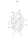
- FIG. 7 is an enlarged view of a region A surrounded by a broken line in FIG.
- the tip end portion 711 of the pin 71 contacts the inclined surface 36 ⁇ / b> B.
- a component force in the direction of the axis 114 is applied to the pin 71 from the inclined surface 36 ⁇ / b> B.
- the pin 71 can be moved to the left along the axis 114.
- the compressed air in the second air chamber 70B flows into the first air chamber 70A via the small hole 76A and the passage 119.
- the left cylindrical force is applied to the pin 71 from the outer cylinder member 35 without reducing the pressure of the first air chamber 70 ⁇ / b> A.
- the compressed air in the second air chamber 70B can be discharged to the first air chamber 70A, and the pin 71 can be moved leftward.
- the compressed air in the first air chamber 70A is discharged to the outside of the main housing 10 through the pressure chamber 30A, or a leftward force is applied to the pin 71 in FIG. Can be moved toward the initial position.
- the check valve 73A opens the passage 119, the moving speed at which the pin 71 shown in FIG. 3C moves to the left is larger than the moving speed at which the pin 71 shown in FIG. 3A moves to the right. can do.
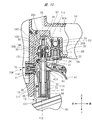
- FIG. 8 shows a state where the push lever 13 shown in FIG. 6 is further raised.
- FIG. 9 shows a contact state between the pin 71 and the outer cylinder member 35 when the push lever 13 shown in FIG. 6 is further raised.
- the pin 71 shown in FIG. 9 is in contact with the vertical surface 36C below the inclined surface 36B, and can push up the push lever 13 so that the pin 71 slides on the vertical surface 36C. State. At this time, the pin 71 moves to the initial position in FIG. 3A.
- the push lever is moved after a predetermined time has elapsed from the time when only the trigger 41 is turned on and the pin 71 moves from the initial position to the restricted position. 13 cannot be switched from off to on.
- the push lever 13 when the push lever 13 is pressed against the driven material 81 within a predetermined time from when the trigger 41 is turned on, for example, before the pin 71 reaches the restriction position, as shown in FIG. And the lock pin engaging portion 36 come into contact with each other, but the pin 71 can be moved to the left as in FIG. 3D to switch the push lever 13 from OFF to ON. That is, in the continuous driving operation, if the waiting time after turning on the trigger 41 exceeds a predetermined time, the driving machine 100 cannot start the first driving operation. On the other hand, if the waiting time is within a predetermined time in the continuous driving operation, the driving machine 100 can start the first driving operation.
- the pin 71 shown in FIG. 8 is stopped at the initial position similarly to the pin 71 shown in FIG. 3A. Even if the push lever 13 is once switched from on to off from the state where the pin 71 is stopped at the initial position as shown in FIG. 8, if the trigger 41 is maintained in the on state, With the compressed air, the pin 71 gradually moves from the initial position in FIG. 3A toward the restriction position in FIG. 3C. The operation of the pin 71 is the same as the operation of the pin 71 when the trigger 41 is turned on from the state where both the trigger 41 and the push lever 13 are turned off.
- the pin 71 is changed from the state of FIG. 3A until the push lever 13 is once again turned off to on after the push lever 13 in the on state is once turned off as shown in FIG. It changes to the state of 3C. That is, when the waiting time from when the push lever 13 is once turned off until the push lever 13 is turned on again is within a predetermined time, the push lever 13 can be switched from off to on again. . On the other hand, if the waiting time from when the push lever 13 is once turned off until the push lever 13 is turned on again exceeds a predetermined time, the pin 71 turns the push lever 13 from off to on. To switch to.
- FIG. 10 shows a situation when the trigger 41 is turned off from the state of FIG. 5 where the push lever 13 cannot be turned on from off.
- the supply of the compressed air to the pressure chamber 30A is stopped, and at the same time, the pressure chamber 30A is opened to the atmosphere via the trigger valve chamber 20A.
- the first air chamber 70A is also released to the atmosphere, the pin 71 moves leftward, and returns to the initial position of FIG. 3A. That is, since both the push lever 13 and the trigger 41 are off, a single shot operation can be performed by turning on the push lever 13 again, and a continuous shot operation is performed again by turning on the trigger 41. Can be made.
- the time required for the pin 71 to move from the initial position to the restricting position can be significantly longer than the time required for the pin 71 to move from the restricting position to the initial position. For this reason, it is possible to suppress the push lever 13 from being turned off to on only when the waiting time in the continuous hitting operation is long, and to enable the push lever 13 from being turned off to on when the waiting time is short. Continuous hitting operation can be performed. At this time, the state where the push lever 13 cannot be turned on can be released in a short time by turning off the trigger 41, and thereafter, either the continuous hitting operation or the single shot hitting operation can be performed. .
- the trigger 41 is turned on when the driving machine 100 performs the first driving operation.
- the operation of turning the push lever 13 from OFF to ON is allowed before the elapse of the first time T1 from the time point.
- the pin 71 restricts switching of the push lever 13 from OFF to ON.
- the first time T1 is the time from when the pin 71 is at the initial position shown in FIG. 3A to when the pin 71 moves to the restriction position shown in FIG. 3C.
- FIG. 8 shows the state of the push lever 13 and the pin driving unit 70 when the driving machine 100 performs the driving operation by switching the push lever 13 from OFF to ON before the first time T1 has elapsed. Show.
- the pin 71 is temporarily turned off when the push lever 13 is turned off once for the next driving operation. After moving to the state, the operation when the driving machine 100 performs the driving operation after that is the same as the case where the driving machine 100 performs the first driving operation.
- the operation of turning the push lever 13 from the off state to the on state is allowed before the first time T1 elapses from the time point when the push lever 13 is turned off.
- the pin 71 regulates the operation of turning the push lever 13 from OFF to ON. Therefore, the first time T1 is preferably in the range of 1 second to 30 seconds, and particularly preferably in the range of 2 seconds to 20 seconds. More preferably, the first time T1 is preferably 3 seconds or longer and 10 seconds or shorter.
- the state of the pin 71 when the push lever 13 is once turned off from the state of FIG. 8 does not have to be exactly the same at the position of FIG. 3A and the position of FIG.
- the position of the pin 71 in FIG. 3A can be set to the right with respect to the position of the pin 71 in FIG.
- the driving machine 100 performs the second and subsequent driving operations
- the position is closer to the restriction position than the position when starting the operation.
- the time-out time when the driving device 100 performs the second and subsequent driving operations is shorter than the time-out time when the driving device 100 performs the first driving operation.
- the pin 71 restricts the push lever 13 from switching from OFF to ON, the trigger 41 is turned OFF, and after the second time T2 has elapsed since the trigger 41 is turned ON again, the pin 71 is The push lever 13 is allowed to be switched from off to on.
- the second time T2 is preferably short, and is preferably at least shorter than the above-described timeout time, that is, the first time T1. If the second time T2 is too long, it takes a long time for the restriction by the pin 71 to be released, so that an efficient operation using the driving machine 100 becomes difficult. For this reason, the second time T2 is preferably set to a range of 1 second or less, particularly 0.5 seconds or less.
- the first time T1 and the second time T2 are the moving speed at which the pin 71 moves rightward in FIGS. 3A and 3B, the moving speed at which the pin 71 moves leftward in FIGS. 3C and 3D, and the lock pin function. It can be adjusted by the shape of the stopper 36, that is, the angle of the lock pin engaging surface 36A and the inclined surface 36B. Among these, the moving speed and moving speed of the pin 71 are adjusted by the air flow amount in the small hole 76A in FIGS. 3A, 3B, 3C and 3D, the air flow amount in the passage 119, and the characteristics of the spring 77. be able to. The amount of air flow in the small hole 76A can be adjusted by setting the opening area of the small hole 76A. The amount of air flow in the passage 119 can be adjusted by the opening area of the passage 119.
- the pin driving unit 70 operates the pin 71 as described above when the trigger 41 and the push lever 13 are operated using only the compressed air used for the driving operation of the driving machine 100. be able to. For this reason, a sensor, an actuator, a motor, or the like used only for operating the pin 71 is unnecessary, and the driving machine 100 can be made inexpensive.
- the compressed air supplied from the trigger valve 20 side to the pressure chamber 30 ⁇ / b> A is used to drive the pin 71.
- a configuration other than the above-described configuration is also possible as a configuration for supplying compressed air to the striking unit according to the movement of the trigger and the push lever.
- the compressed air for driving the regulating member can be appropriately set according to the compressed air path in such a case.
- the pin 71 is in the initial state by the movement of the lock pin engaging portion 36 when performing control for the second and subsequent driving in the continuous driving operation.
- the pin 71 may be in the initial state by removing the compressed air from the first air chamber 70A after the driving device 100 has completed one driving operation.
- the restriction on the movement of the push lever 13 as described above is applied only to the first driving operation of the continuous driving operation, and is not applied to the second driving operation and thereafter. Also good.
- the guide member 91 supports the plunger guide 120.
- the plunger guide 120 has a cylindrical shape, and the push lever plunger 31 is movable in the direction of the axis 115 within the shaft hole 121 of the valve body 32 and the plunger guide 120. Further, the push lever plunger 31 is rotatable with respect to the plunger guide 120 about the axis 115.
- An elastic member 122 is disposed between the hook 110 and the plunger guide 120.
- the elastic member 122 is, for example, a metal compression spring. The elastic member 122 biases the push lever 13 downward in FIG.
- the push lever plunger 31 has a groove 123.
- the groove 123 is provided in a predetermined range in the direction of the axis 115 as shown in FIG.
- An urging member 124 is provided in the shaft hole 121, and the urging member 124 is, for example, a metal compression spring. A part of the urging member 124 is disposed in the groove 123, and the urging member 124 is pressed against the push lever plunger 31.
- the biasing member 124 applies a biasing force in the circumferential direction about the axis 115 to the push lever plunger 31.
- FIG. 12 shows a structure in which the biasing member 124 applies a clockwise biasing force to the push lever plunger 31 as an example.
- a groove 139 is provided on the outer peripheral surface of the push lever plunger 31. The groove 139 is provided with a predetermined length in the direction of the axis 115.
- the contact protrusion 125 is provided at the end closest to the push lever arm 131 in the longitudinal direction of the push lever 13.
- One contact protrusion 125 is provided in the circumferential direction around the axis 115 or a plurality, for example, two are provided at intervals.
- a block 127 is fixed to the hook 110, and the block 127 has a contact protrusion 126.
- One, or a plurality of, for example, two contact protrusions 126 are provided in the circumferential direction around the axis 115.
- the two contact protrusions 125 and the two contact protrusions are disposed on the same circumference.
- a pin driving portion 128 is provided on a wall portion 155 that forms the return chamber 10 ⁇ / b> A of the main housing 10.
- the pin driving unit 128 includes an outer cylinder member 129, an inner cylinder member 130, and a pin 152.
- the outer cylinder member 129 and the inner cylinder member 130 are provided around the axis 114.
- the axis 114 intersects with the axis 115, for example, at a right angle.
- a passage 132 that penetrates the outer cylinder member 129 in the radial direction is provided.
- the outer cylinder member 129 has a wall portion 149 that protrudes inward in the radial direction.
- the wall portion 149 is provided at a location closest to the plunger guide 120 in the direction of the axis 134.
- An axial hole 133 that penetrates the wall portion 149 in the direction of the axis 134 is provided.
- the shaft hole 133 is provided around the axis 134.
- the inner cylinder member 130 is provided in the outer cylinder member 129 and is provided so as not to move in the direction of the axis 134.
- a passage 135 is provided between the outer cylinder member 129 and the inner cylinder member 130, and the passage 132 connects the passage 135 and the control flow path 10C.
- the inner cylinder member 130 includes a cylinder part 136 and a wall part 137 in which one end part in the longitudinal direction of the cylinder part 136 is closed.
- a shaft hole 138 that penetrates the plunger guide 120 in and out is provided.
- the pin 152 has a large diameter part 147, a small diameter part 148, and a land part 140.
- the outer diameter of the large diameter portion 147 is larger than the outer diameter of the small diameter portion 148.
- a step portion 153 is provided at the boundary between the large diameter portion 147 and the small diameter portion 148.
- the step portion 153 is perpendicular to the axis 134 and is an annular plane.
- the large diameter portion 147 is disposed in the cylindrical portion 136, and the small diameter portion 148 is disposed over the shaft holes 133 and 138.
- the pin 152 is movable in the direction of the axis 134.
- the land portion 140 protrudes in the radial direction from the outer peripheral surface of the large diameter portion 147 and is provided in an annular shape.
- a seal member 141 is attached to the outer peripheral surface of the land portion 140.
- an air chamber 142 is provided between the land portion 140 and the outer cylinder member 129.
- the seal member 141 seals the air chamber 142.
- a seal member 150 is attached to the inner surface of the shaft hole 133 in the wall portion 149, and the seal member 150 seals the air chamber 142.
- a passage 143 that penetrates the cylindrical portion 136 in the radial direction is provided, and the passage 143 connects the passage 135 and the air chamber 142.
- the opening area of the passage 143 is narrower than the opening area of the passage 132.
- a passage 144 that penetrates the cylindrical portion 136 in the radial direction is provided, and a check valve 145 that opens and closes the passage 144 is provided.
- the check valve 145 allows air in the air chamber 142 to flow into the passage 135 via the passage 144.
- the check valve 145 prevents the air in the passage 135 from flowing into the air chamber 142 via the passage 144.
- the opening area of the passage 144 is wider than the opening area of the passage 143.
- an elastic member 146 is provided between the wall portion 137 and the land portion 140.
- the elastic member 146 urges the pin 152 in the right direction along the axis 134 in FIG. 14, that is, in a direction approaching the plunger guide 120.
- Specific example 2 of the restriction mechanism 154 includes a pin drive unit 128, a push lever plunger 31, an urging member 124, and a block 127.
- the trigger valve 20 When the compressed air is supplied to the pressure accumulating chamber 50A and the operating force is not applied to the trigger 41 as shown in FIG. 11, the trigger valve 20 is off, that is, closed.
- the push lever 13 When the push lever 13 is away from the workpiece 81, the push lever valve 30 is off, that is, in the closed state.
- the push lever 13 is pushed by the urging force of the elastic member 122, the hook 110 is engaged with the stopper 111, and the push lever 13 is stopped at the initial position.
- the action of the trigger valve 20 being closed is the same as in FIG.
- the push lever plunger 31 is biased by a biasing member 124 as shown in the upper part of FIG.
- the pin 152 is stopped at the initial position, the small diameter portion 148 of the pin 152 is positioned in the groove 139 and the pin 152 is pressed against the push lever plunger 31 as shown in the upper part of FIG. For this reason, the push lever plunger 31 is stopped at the first position P1 in the circumferential direction.
- the first position P1 will be described with reference to a location where the biasing member 124 is in contact with the push lever plunger 31.
- the contact protrusion 125 and the contact protrusion 126 are at the same position in the circumferential direction of the push lever plunger 31, as shown in the upper part of FIG. Further, as shown in the upper part of FIG. 16, the contact protrusion 125 and the contact protrusion 126 are in contact with each other.
- the trigger valve 20 when the operator applies an operating force to the trigger 41 in a state where the trigger 41 is turned off and the push lever 13 is turned off, the trigger valve 20 is switched from off to on.
- the trigger valve 20 is switched from OFF to ON, the compressed air in the pressure accumulating chamber 50A is sent to the trigger valve chamber 20A, the pressure chamber 30A, the control channel 10C, and the passages 132 and 135.
- the air sent to the passage 135 gradually flows into the air chamber 142 via the passage 143, and the pressure of the air chamber 142 increases.
- the pressure of the air chamber 142 applies an urging force opposite to the urging force of the elastic member 146 to the pin 152. That is, the pin 152 receives a leftward force in FIG. 14, that is, a force away from the push lever plunger 31 due to the pressure of the air chamber 142.
- the push lever plunger 31 is stopped at the first position P1 shown in the upper part of FIG. 12, or the angle at which the push lever plunger 31 moves in the circumferential direction from the first position P1 is lower in FIG. Is less than a predetermined angle ⁇ 1. For this reason, in the circumferential direction of the push lever plunger 31, the position of the contact protrusion 125 and the position of the contact protrusion 126 overlap at least partially as shown in the upper part of FIG.
- the push lever plunger 31 shown in FIG. 11 moves up along the axis 115.
- the small diameter portion 148 of the pin 152 slides in the groove 139.
- the push lever plunger 31 is pressed against the valve member 33 after the push lever plunger 31 blocks the exhaust passage 151 and the push lever valve chamber 30B.
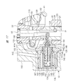
- the valve member 33 is lifted along the axis 115 as shown in FIG. 17 by the moving force of the push lever plunger 31, and the push lever valve 30 is turned on, that is, the push lever valve 30 is opened as shown in FIG.
- the compressed air is sent to the driving channel 10B through the pressure chamber 30A and the push lever valve chamber 30B. Therefore, in the driving machine 100 shown in FIG. 1, the hitting unit 16 performs a driving operation.
- the compressed air in the passage 135 flows through the passage 132 and the control passage 10C to the pressure chamber 30A, and the pressure in the passage 135 decreases. To do.
- the check valve 145 opens and the compressed air in the air chamber 142 is discharged to the passage 135 through the passage 144. For this reason, the pressure of the air chamber 142 decreases, the pin 152 moves by the urging force of the elastic member 146, and the pin 152 stops at the initial position.
- the push lever 13 After the hitting portion 16 performs the driving operation, when the operator keeps the trigger 41 on and releases the push lever 13 from the driven material 81, the push lever 13 is urged by the urging force of the elastic member 122 as shown in FIG.
- the push lever plunger 31 opens the exhaust passage 151. For this reason, the compressed air in the driving flow path 10 ⁇ / b> B passes through the push lever valve chamber 30 ⁇ / b> B and the exhaust passage 151 and is discharged to the outside of the main housing 10. Further, when the hook 110 is engaged with the stopper 111, the push lever 13 stops at the initial position.
- the push lever plunger 31 While the movement amount of the pin 152 is less than the predetermined amount, the push lever plunger 31 is urged clockwise from the urging member 124 as shown in FIG. For this reason, the angle at which the push lever plunger 31 operates in the circumferential direction is increasing. And if the moving amount
- the predetermined angle ⁇ 1 is 45 degrees as an example.
- the operator presses the push lever 13 against the workpiece 81 after a predetermined time has elapsed from when the trigger 41 is switched from off to on, and the push lever 13 resists the force of the elastic member 122. 11, the contact protrusion 126 does not contact the push lever plunger 31 and the contact protrusion 125 does not contact the block 127 even when moved upward in FIG. 11. For this reason, the moving force of the push lever 13 is not transmitted to the push lever plunger 31.
- the push lever 13 moves downward in FIG. 17 by the urging force of the elastic member 122, and the push lever plunger 31 opens the exhaust passage 151. Further, the push lever 13 stops when the hook 110 is engaged with the stopper 111.
- the push lever 13 is driven into the target material within a predetermined time from when the trigger valve 20 is switched from off to on.
- the restriction mechanism 154 allows the push lever valve 30 to switch from OFF to ON, and the striking portion 16 performs a driving operation.
- the push lever 13 is not covered after a predetermined time from when the trigger valve 20 is switched from off to on.
- the restricting mechanism 154 restricts the push lever valve 30 from switching from OFF to ON, and the striking portion 16 does not perform the driving operation.
- the restriction mechanism 154 releasing the restriction applied to the push lever valve 30 will be described.
- the restricting mechanism 154 restricts the push lever valve 30 from switching from off to on
- the trigger valve 20 is switched from on to off.
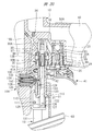
- the compressed air in the pressure chamber 30A is discharged to the outside of the main housing 10 through the trigger valve chamber 20A and the shaft hole 95, and the pressure in the pressure chamber 30A decreases.
- the check valve 145 opens, and the compressed air in the air chamber 142 flows into the pressure chamber 30A through the passage 144, the passage 135, the passage 132, and the control flow passage 10C.
- the pressure drops.
- the pin 152 moves in a direction approaching the push lever plunger 31 in FIG. 19 by the biasing force of the elastic member 146. Then, a counterclockwise turning force is applied from the pin 152 to the push lever plunger 31 in the lower stage of FIG.
- the push lever plunger 31 operates counterclockwise at the lower stage of FIG. 12 against the urging force of the urging member 124, and returns to the first position P1 shown at the upper stage of FIG. 12 and stops.
- the relative position between the contact protrusion 125 and the contact protrusion 126 is in the state shown in the upper part of FIG. Therefore, the restriction applied to the push lever valve 30 by the restriction mechanism 154 is released. That is, when the push lever 13 is pressed against the driven material 81, the moving force of the push lever 13 is transmitted to the valve member 33 via the push lever plunger 31, and the push lever valve 30 can be switched from OFF to ON. .
- the operation speed when the pin 152 moves away from the wall portion 137 by the urging force of the elastic member 146 for a predetermined time is determined according to the opening area of the passage 143 and the spring constant of the elastic member 146.
- the restriction mechanism 154 includes a pin driving unit 70, a first plunger 161, a second plunger 156, and elastic members 157, 158, 159.
- the configuration of the pin driver 70 is the same as the configuration of the pin driver 70 shown in FIGS. 3A, 3B, 3C, and 3D.
- the first plunger 161 is fixed to the push lever 13.
- the second plunger 156 is disposed between the first plunger 161 and the valve member 33 in the direction of the axis 115. Both the first plunger 161 and the second plunger 156 are arranged concentrically around the axis 115. A part of the first plunger 161 is disposed in the shaft hole 121, and the first plunger 161 is movable in the direction of the axis 115 in the shaft hole 121.
- the second plunger 156 is disposed over the shaft hole 121 and the valve body 32, and the second plunger 156 is movable in the direction of the axis 115.
- the elastic member 157 is disposed between the push lever 13 and the plunger guide 120.
- the elastic member 157 is a metal compression spring, for example, and the elastic member 57 urges the push lever 13 downward in FIG.
- the elastic member 158 is disposed between the first plunger 161 and the second plunger 156.
- the elastic member 158 is, for example, a metal compression spring, and both ends of the elastic member 158 in the direction of the axis 115 are in contact with the first plunger 161 and the second plunger 156, respectively.
- the elastic member 159 is, for example, a metal compression spring, and both ends of the elastic member 159 in the direction of the axis 115 are in contact with the second plunger 156 and the valve member 33, respectively.
- the second plunger 156 has an annular engagement groove 160.
- a shaft hole 138 that penetrates the plunger guide 120 in the radial direction is provided, and when the pin 71 moves in the direction of the axis 114, the tip portion 711 enters and exits into the shaft hole 121 of the plunger guide 120 through the shaft hole 138. Is possible.
- the push lever 13 is separated from the workpiece 81, the push lever 13 is stopped at the initial position. For this reason, moving force is not transmitted from the first plunger 161 to the second plunger 156 from the push lever 13, and the second plunger 156 is stopped at the initial position.
- the urging force applied from the second plunger 156 to the valve member 33 is the minimum value. For this reason, the valve member 33 biased by the spring 34 is stopped in a state where the seal member 97 is pressed against the valve body 32. Therefore, the push lever valve 30 is off, that is, in a closed state.
- the second plunger 156 connects the push lever valve chamber 30 ⁇ / b> B and the exhaust passage 151. For this reason, the compressed air in the driving flow path 10 ⁇ / b> B is discharged to the outside of the main housing 10 through the push lever valve chamber 30 ⁇ / b> B and the exhaust passage 151.
- the trigger valve 20 When the operator applies an operating force to the trigger 41 in a state where the trigger valve 20 is turned off and the push lever valve 30 is turned off, the trigger valve 20 is switched from off to on.
- the trigger valve 20 When the trigger valve 20 is switched from OFF to ON, the compressed air in the pressure accumulating chamber 50A passes through the trigger valve chamber 20A, the pressure chamber 30A, the control flow channel 10C, the passage 118, the first air chamber 70A, and the small hole 76A. 2 Flows into the air chamber 70B. Then, the pressure in the second air chamber 70B gradually increases.
- the compressed air in the pressure accumulating chamber 50A passes through the trigger valve chamber 20A, the pressure chamber 30A, the control flow channel 10C, the passage 118, and the small hole 76A, and the second air chamber 70B.
- the pressure in the second air chamber 70B increases. For this reason, the pin 71 moves in the direction of the axis 114 in a direction approaching the second plunger 156 against the urging force of the spring 77.
- the trigger valve 20 is switched from OFF to ON within a predetermined time, the amount of movement of the pin 71 in the direction approaching the second plunger 156 from the initial position is less than the predetermined value, and the tip 711 is engaged. It does not enter the groove 160.
- the first plunger 161 resists the urging force of the elastic member 157. Then, it moves upward along the axis 115 in FIG. Then, the moving force of the first plunger 161 is transmitted to the second plunger 156 via the elastic member 158, and the second plunger 156 moves upward along the axis 115 in FIGS. For this reason, the second plunger 156 blocks the exhaust passage 151 and the push lever valve chamber 30B. Further, the moving force of the second plunger 156 is transmitted to the valve member 33 via the elastic member 159. As a result, the valve member 33 moves upward as shown in FIG. 23, and the push lever valve 30 is turned on, that is, opened.
- the striking unit 16 performs a driving operation.
- the compressed air in the passage 118 flows from the control channel 10C to the pressure chamber 30A, and the pressure in the passage 118 decreases.
- the check valve 73A opens, the compressed air in the second air chamber 70B is discharged to the passage 118, and the pressure in the second air chamber 70B decreases.
- the pin 71 moves in a direction away from the second plunger 156 by the biasing force of the spring 77, returns to the initial position, and stops. Further, the check valve 73A is closed.
- the second plunger 156 operates downward in FIG. 23 by the biasing force of the elastic member 159 to connect the push lever valve chamber 30B and the exhaust passage 151, and then stops at the initial position shown in FIG. Further, the valve member 33 operates downward in FIG. 23 by the biasing force of the spring 34, and the push lever valve 30 is turned off, that is, closed as shown in FIG.
- the tip portion 711 of the pin 71 passes through the shaft hole 138 and enters the shaft hole 121 of the plunger guide 120, and FIG. Stop at the restricted position as shown. That is, the tip 711 enters the engagement groove 160.
- the push lever 13 is driven into the target material within a predetermined time from when the trigger valve 20 is switched from off to on.
- the restriction mechanism 154 allows the push lever valve 30 to switch from OFF to ON, and the striking portion 16 performs a driving operation.
- the push lever 13 is not covered after a predetermined time from when the trigger valve 20 is switched from off to on.
- the restricting mechanism 154 restricts the push lever valve 30 from switching from OFF to ON, and the striking portion 16 does not perform the driving operation.
- the restriction mechanism 154 restricts the push lever valve 30 from switching from off to on, when the operator releases the operating force on the trigger 41, the trigger valve 20 is switched from on to off. Then, the compressed air in the pressure chamber 30A is discharged to the outside of the main housing 10 through the trigger valve chamber 20A and the shaft hole 95, and the pressure in the pressure chamber 30A decreases.
- the check valve 73A opens, and the compressed air in the second air chamber 70B flows into the pressure chamber 30A through the passage 119, the passage 118, and the control flow passage 10C.
- the pressure of 70B decreases.
- the pin 71 moves in a direction away from the push lever plunger 31 in FIGS. 25 and 26 by the biasing force of the spring 77.
- the tip 711 comes out of the shaft hole 138 as shown in FIG. Therefore, the restriction applied to the push lever valve 30 by the restriction mechanism 154 is released. That is, when the push lever 13 is pressed against the driven material 81 shown in FIG. 1, the moving force of the push lever 13 is transmitted to the valve member 33 via the first plunger 161 and the second plunger 156, and the push lever valve 30. Can be switched from off to on.
- the driving machine 200 shown in FIG. 27 includes a main housing 201, a handle 202, It has a nose 203, a cylinder 204, a striking part 205, a trigger valve 206, a push lever 207, a trigger 208 and a magazine 209.
- the main housing 201 is connected to the handle 202, and a pressure accumulating chamber 210 is formed across the main housing 201 and the handle 202.
- An air hose is attached to and detached from the handle 202, and compressed air is supplied from the air hose into the pressure accumulating chamber 210.
- the main housing 201 has a cylindrical shape, and the nose 203 has a cylindrical portion 239 and a flange 240.
- the flange 240 is provided at the end of the cylindrical portion 239 in the longitudinal direction.
- a nose 203 is fixed to the flange 240 at a first end 219 in the longitudinal direction of the main housing 201.
- An outer cylinder portion 211 and an inner cylinder portion 212 are provided on the inner surface of the second end portion 220 in the longitudinal direction of the main housing 201.
- the outer cylinder portion 211 and the inner cylinder portion 212 are provided around the axis 213.
- the longitudinal direction of the main housing 201 is a direction parallel to the axis 213.
- the axis 213 is the center of the cylinder 204.
- the outer cylinder part 211 is arranged outside the inner cylinder part 212, and the movable member 214 is arranged between the outer cylinder part 211 and the inner cylinder part 212.
- the movable member 214 is an annular body centered on the axis 213.
- a seal member 215 is provided between the movable member 214 and the outer cylinder portion 211, and a seal member 216 is provided between the movable member 214 and the inner cylinder portion 212.
- the movable member 214 is disposed between the cylinder 204 and the second end 220 in the direction of the axis 213.
- the movable member 214 is movable in parallel with the axis 213.
- a head valve 225 is attached to the movable member 214.
- the head valve 225 is annular, and is made of synthetic rubber as an example.
- the head valve 225 is movable in parallel with the axis 213 of the cylinder 204 together with the movable member 214.
- the head valve 225 can contact and separate from the end of the cylinder 204 in the direction of the axis 213.
- a head valve chamber 217 is provided between the outer cylinder portion 211, the inner cylinder portion 212, and the movable member 214.
- a biasing member 224 is disposed in the head valve chamber 217.
- the urging member 224 urges the movable member 214 in a direction along the axis 213 so as to approach the cylinder 204.
- the biasing member 224 is, for example, a metal compression spring.
- An air passage 218 connected to the head valve chamber 217 is provided in the main housing 201.
- a cover 221 is attached to the second end 220, and the cover 221 holds the bumper 222.
- the bumper 222 is disposed on the inner side of the inner cylindrical portion 212 and the inner side of the movable member 214 in the radial direction centering on the axis 213.
- the bumper 222 is a buffer member made of synthetic rubber as an example.
- An exhaust passage 223 is provided between the bumper 222 and the inner cylindrical portion 212 and between the cover 221 and the second end portion 220.
- the striking portion 205 includes a piston 226, a driver blade 227, and a piston upper chamber 229.
- the piston 226 is movable in the direction of the axis 213 in the cylinder 204, and the driver blade 227 is fixed to the piston 226.
- a seal member 228 is attached to the outer peripheral surface of the piston 226.
- a piston upper chamber 229 is formed between the piston 226 and the bumper 222 in the cylinder 204.
- a port 230 is formed between the bumper 222 and the movable member 214. When the movable member 214 moves in the direction of the axis 213, the movable member 214 and the bumper 222 come into contact with and separate from each other, and the port 230 is opened and closed. When the port 230 is opened, the piston upper chamber 229 and the exhaust passage 223 are connected, and when the port 230 is closed, the piston upper chamber 229 and the exhaust passage 223 are blocked.
- a port 231 is formed between the head valve 225 and the end of the cylinder 204.
- the head valve 225 operates in the direction of the axis 213, the head valve 225 and the cylinder 204 come into contact with and separate from each other, and the port 231 is opened and closed.
- the port 231 is opened, the pressure accumulation chamber 210 and the piston upper chamber 229 are connected.
- the port 231 is closed, the pressure accumulation chamber 210 and the piston upper chamber 229 are shut off.
- a bumper 232 is provided in the cylinder 204 at the end closest to the nose 203.
- the bumper 232 is a buffer member made of synthetic rubber as an example.
- the bumper 232 has a shaft hole 233.
- a wall portion 235 is provided on the inner surface of the main housing 201 and the connection portion of the handle 202.
- the wall portion 235 holds the holder 236.
- the holder 236 has an annular shape, and the holder 236 supports the cylinder 204 so as to be movable in the direction of the axis 213.
- the holder 236 positions the cylinder 204 in the radial direction.
- a piston lower chamber 234 is provided between the piston 226 and the bumper 232 in the cylinder 204.
- a partition wall 241 is provided outside the outer peripheral surface of the cylinder 204.
- the partition wall 241 is provided over the entire circumference of the cylinder 204.
- the partition wall 241 is provided between the holder 236 and the bumper 232 in the direction of the axis 213.
- a seal member 242 is attached to the outer peripheral surface of the partition wall 241. The seal member 242 contacts and seals the inner surface of the main housing 201 and the inner surface of the wall portion 235.
- a return chamber 237 is provided in the main housing 201.
- the return chamber 237 is provided between the main housing 201 and the wall portion 235 and the cylinder 204 and between the partition wall 241 and the first end portion 219.
- a passage 238 passing through the cylinder 204 in the radial direction is provided.
- a passage 238 connects the piston lower chamber 234 and the return chamber 237.
- a check valve 243 is provided in the return chamber 237. The check valve 243 allows the compressed air in the piston lower chamber 234 to flow into the return chamber 237 and prevents the compressed air in the return chamber 237 from flowing into the piston lower chamber 234.
- a passage 244 that penetrates the cylinder 204 in the radial direction is provided. The passage 244 connects the piston lower chamber 234 and the return chamber 237.
- a reset chamber 245 is provided between the cylinder 204 and the main housing 201 and the wall portion 235.
- the reset chamber 245 is provided between the holder 236 and the partition wall 241 in the direction of the axis 213.
- a passage 246 penetrating the cylinder 204 in the radial direction is provided.
- the passage 246 connects the piston lower chamber 234 and the reset chamber 245.
- a check valve 247 is provided in the reset chamber 245. The check valve 247 allows the compressed air in the piston lower chamber 234 to flow into the reset chamber 245 and prevents the compressed air in the reset chamber 245 from flowing into the piston lower chamber 234.
- the cylindrical portion 239 is disposed along the direction of the axis 213, and the cylindrical portion 239 has an injection path 248.
- the injection path 248 and the shaft hole 233 are arranged concentrically around the axis 213.
- the driver blade 227 is movable in the direction of the axis 213 within the shaft hole 233 and the injection path 248.
- the push lever 207 is attached to the cylinder portion 239 so as to be movable in the direction of the axis 213.
- the magazine 209 accommodates the nail 80.
- a plurality of nails 80 are connected to each other.
- the magazine 209 accommodates a plurality of nails 80 arranged in a spiral.
- the magazine 209 has a feed mechanism that feeds the nails 80 one by one to the injection path 248.
- a regulation mechanism 316 shown in FIG. 29 includes a timeout valve 315, a lock valve 293, and a holder 254.
- An arm 318 connected to the push lever 207 is provided, and a pin 253 is attached to the arm 318.
- the pin 253 can move in the direction of the axis 213 together with the push lever 207.
- a holder 254 is attached to the pin 253.
- the holder 254 has a cylindrical portion 255, and the holder 254 holds the plunger 256.
- the pin 253 holder 254 and the plunger 256 are operable in the direction of the axis 257.
- the axis 257 is parallel to the axis 213.
- the nose 203 has a support portion 305.
- a cylinder 258 is attached to the plunger 256.
- the cylinder 258 is movable in the direction of the axis 257 with respect to the plunger 256.
- the plunger 256 has a disc portion 259, and an elastic member 260 is provided between the disc portion 259 and the cylinder 258.
- the elastic member 260 is a metal compression spring as an example.
- the elastic member 260 generates a biasing force that separates the disk portion 259 and the cylinder 258 in the direction of the axis 257.
- a stopper 261 is provided on the wall 235, and the cylinder 258 biased by the elastic member 260 is fixed to the wall 235 by the stopper 261.
- the cylinder 258 has a cylindrical portion 262 and is provided with a shaft hole 263 that penetrates the cylindrical portion 262 in the radial direction.
- the plunger 256, the holder 254, and the pin 253 urged in the direction of the axis 257 by the elastic member 260 are stopped when the holder 254 contacts the support portion 305.
- the trigger 208 is supported so as to be rotatable about the support shaft 249 with respect to the main housing 201.
- a trigger arm 250 is attached to the trigger 208 so as to be rotatable about a support shaft 251.
- a biasing member 252 that biases the trigger arm 250 is provided.
- the biasing member 252 is a metal compression spring as an example. In FIG. 29, the urging member 252 urges the trigger arm 250 clockwise about the support shaft 251.
- the configuration of the trigger valve 206 will be described.
- the trigger valve 206 includes a trigger valve guide 264, a plunger guide 265, a valve member 266, and plungers 267 and 268.
- the wall 235 is provided with a recess 269, and the trigger valve guide 264 is provided in the recess 269.
- the trigger valve guide 264 has a cylindrical shape with the axis 270 as the center. The trigger valve guide 264 does not move in the direction of the axis 270 with respect to the wall 235. Further, the trigger valve guide 264 and the inner surface of the wall portion 235 are sealed with a seal member 271.
- the plunger guide 265 is provided inside the trigger valve guide 264.
- the plunger guide 265 does not move in the direction of the axis 270 with respect to the trigger valve guide 264.
- the plunger guide 265 has a cylindrical shape and has a shaft hole 273.
- a passage 274 parallel to the axis 270 is provided on the outer peripheral surface of the plunger guide 265. The passage 274 connects the inside 272 and the outside of the main housing 201.
- the plunger 267 is disposed in the shaft hole 273 and outside the main housing 201 and is movable in the direction of the axis 270.
- the end of the plunger 267 contacts the trigger arm 250.
- a seal member 312 is attached to the outer peripheral surface of the plunger 267.
- the valve member 266 is disposed in the trigger valve guide 264.
- the valve member 266 is movable in the direction of the axis 270 with respect to the trigger valve guide 264.
- a passage 275 is formed between the valve member 266 and the trigger valve guide 264.
- a passage 276 passing through the trigger valve guide 264 in the radial direction is provided, and the passage 276 connects the passage 275 and the air passage 218.
- Seal members 277 and 278 are attached to the outer peripheral surface of the valve member 266. When the seal member 277 is pressed against the inner surface of the trigger valve guide 264, the seal member 277 blocks the pressure accumulation chamber 210 and the passage 275. When the seal member 277 is separated from the inner surface of the trigger valve guide 264, the pressure accumulating chamber 210 and the passage 275 are connected.
- the seal member 314 When the seal member 314 is pressed against the inner surface of the trigger valve guide 264, the seal member 314 blocks the passage 276 and the passage 274. When the seal member 277 is separated from the inner surface of the trigger valve guide 264, the passage 276 and the passage 274 are connected.
- the plunger guide 265 has a recess 310, and a part of the plunger 268 in the longitudinal direction is disposed in the recess 310.
- the plungers 267 and 268 are arranged coaxially with respect to the axis 270 and in series.
- a part of the valve member 266 is disposed in the recess 310.
- a seal member 280 is attached to the outer peripheral surface of the valve member 266.
- the seal member 280 blocks the inside of the recess 310 and the inside 272.
- a spring 307 is provided between the plunger 268 and the valve member 266.
- the spring 307 is a metal compression spring as an example.
- the plunger 268 is pressed against the step portion 306 by the biasing force of the spring 307.
- the valve member 266 is biased in the direction away from the step portion 306 in the direction of the axis 270 by the biasing force of the spring 307.
- a seal member 308 is attached to the outer peripheral surface of the plunger 26. When the seal member 308 is separated from the valve member 266, the pressure accumulation chamber 210 is connected to the space 309 through the recess 310. When the seal member 308 comes into contact with the valve member 266, the pressure accumulating chamber 210 and the recess 310 are shut off.
- the recess 310 and the shaft hole 273 are connected, and a space 309 is formed between the plunger 268 and the plunger 267.
- a step portion 306 is provided at a location where the recess 310 and the shaft hole 273 are connected.
- the step portion 306 is an end surface perpendicular to the axis 270.
- a space 309 is provided between the plunger 267 and the plunger 268. The space 309 is connected to the recess 310.
- a timeout valve 315 is provided on the wall 235.
- the time-out valve 315 includes a valve member 319, a time-out valve chamber 279, and a spring 320 as shown in FIG.
- the timeout valve chamber 279 is connected to the reset chamber 245 through the passage 283.
- the valve member 319 has a large diameter portion 285 and a small diameter portion 286.
- the valve member 319 has timer passages 281 and 282.
- the timer passage 281 penetrates the small diameter portion 286 in the radial direction, and the timer passage 281 is connected to the timeout valve chamber 279.
- the opening area of the timer passage 281 is narrower than the opening area of the timer passage 282.
- a passage 290 is provided in the wall portion 235, and the timer passage 281 is connected to the passage 290.
- the passage 290 is connected to the space 309 as shown in FIG.
- An accommodating portion 287 is formed in the wall portion 235, and the valve member 319 is movable in the direction of the axis 288 within the accommodating portion 287.
- the time-out valve chamber 279 is disposed on the one end side of the valve member 319 in the direction of the axis 288 in the accommodating portion 287.
- a seal member 289 is attached to the outer peripheral surface of the large diameter portion 285.
- the seal member 289 seals between the passage 290 and the timeout valve chamber 279.
- a space 284 is formed between the inner surface of the accommodating portion 287 and the outer peripheral surface of the small diameter portion 286.
- the space 284 is connected to the passage 290 regardless of the position of the valve member 319 in the direction of the axis 288.
- a space 291 is formed between the inner surface of the accommodating portion 287 and the end surface of the small diameter portion 286.
- the space 291 is connected to the timer passage 281.
- a seal member 292 is attached to the outer peripheral surface of the small diameter portion 286.
- the spring 320 is a metal compression spring as an example. The spring 320 urges the valve member 319 in the direction of narrowing the space 291 in the direction of the axis 288.
- a lock valve 293 is provided on the wall portion 25.
- the lock valve 293 includes a storage chamber 294, a lock pin 295, and a spring 296.
- the lock pin 295 can move in the direction of the axis 301.
- the lock pin 295 has a large diameter portion 297 and a small diameter portion 298.
- the outer diameter of the large diameter portion 297 is larger than the outer diameter of the small diameter portion 298.
- a lock chamber 311 is formed between the large diameter portion 297 and the inner surface of the storage chamber 294.
- a passage 299 is provided in the wall portion 235, and the passage 299 connects the lock chamber 311 and the timeout valve chamber 279.
- a shaft hole 300 is provided in the wall portion 235, and the small-diameter portion 298 is disposed over the shaft hole 300 and the shaft hole 263.
- the small diameter portion 298 is movable in the direction of the axis 301 within the shaft hole 300 and the shaft hole 263.
- a seal member 302 is provided between the shaft hole 300 and the small diameter portion 298.
- a seal member 303 is provided on the outer peripheral surface of the large diameter portion 297. Seal members 302 and 303 seal the lock chamber 311.
- the spring 296 is, for example, a metal compression spring.
- the spring 296 urges the lock pin 295 in the direction of approaching the holder 254 in the direction of the axis 301.
- a passage 304 is provided in the wall 235.
- the passage 304 connects the space in the accommodation chamber 294 where the spring 296 is disposed and the outside of the main housing 10.
- the initial state of the driving machine 200 is a state in which the operator does not apply an operating force to the trigger 208 and the push lever 207 is separated from the driven material 81. It can be grasped as the trigger 208 being turned off that the operator does not apply operating force to the trigger 208.
- the state in which the push lever 207 is separated from the workpiece 81 can be grasped as the push lever 207 being turned off.
- the push lever 207 is restricted from moving in the direction away from the flange 240 in the direction of the axis 213. Further, since the small diameter portion 298 is located in the shaft hole 263, the cylinder 258 is prevented from moving in the direction of the axis 257.
- the valve member 319 is pressed by the urging force of the spring 28, the large diameter portion 285 is pressed against the wall portion 235, and the valve member 319 is stopped. Further, the seal member 292 is in contact with the inner surface of the wall portion 235. For this reason, the space 291, the passage 290, and the space 284 are blocked. Further, as shown in FIG. 32, the trigger arm 250 and the trigger 208 that receive the urging force of the urging member 252 are both stopped at the initial position in contact with the cylinder 258.
- the seal member 277 has a trigger valve guide away from 264. For this reason, the pressure accumulating chamber 210 and the passage 275 are connected. Further, the seal member 314 is pressed against the trigger valve guide 264. The seal member 314 blocks the passage 275 and the passage 274.
- the urging force of the urging member 224 is transmitted to the cylinder 204 via the movable member 214 and the head valve 225.
- the end of the cylinder 204 in the direction of the axis 213 is pressed against the flange 240, and the cylinder 204 is stopped.
- the port 231 is closed.
- the movable member 214 is away from the bumper 222 and the port 230 is open.
- the piston 226 contacts the bumper 222, and the hitting portion 205 stops at the top dead center.
- the compressed air in the pressure accumulating chamber 210 is converted into a space 313 between the valve member 266 and the plunger 268, It flows into the space 309 through the recess 310. Then, the plunger 267 is pressed against the trigger arm 250 by the pressure of the compressed air, and the space 309 and the passage 290 are connected.
- the element to which the operating force is transmitted is divided into two plungers 267 and 268. Therefore, in a state where compressed air is supplied to the pressure accumulating chamber 210, the trigger arm 250 is pushed downward in FIG. 32 by the pressure of the compressed air sent from the pressure accumulating chamber 210 to the space 309, and the trigger 208 contacts the cylinder 358. To stop at the initial position. Therefore, it is not necessary to provide a biasing member that biases the trigger 208 toward the cylinder 358 in order to hold the trigger 208 in the initial position.
- the state where the space 309 and the passage 290 are connected can be grasped as the trigger valve 206 being on.
- the compressed air in the space 309 flows into the timer passage 281 through the passage 290.
- the valve member 319 moves in a direction approaching the passage 299 against the biasing force of the spring 320.
- the space 284 is connected to the timer passage 282 through the space 291.
- the compressed air is supplied to the lock chamber 311 through the spaces 284, 291, the timer passage 282, the timeout valve chamber 279 and the passage 299.
- the large diameter portion 297 receives the pressure of the compressed air, and the lock pin 295 moves away from the holder 254 against the urging force of the spring 296. For this reason, the small diameter portion 298 moves out of the cylindrical portion 262. Accordingly, the push lever 207 can move in a direction approaching the flange 240 in FIG.
- the check valve 247 is closed by the pressure in the reset chamber 245.
- valve member 319 When the pressure in the passage 290 and the pressure in the passage 299 become the same, the valve member 319 operates in a direction away from the passage 299 by the biasing force of the spring 320, and the end surface of the large diameter portion 285 is a wall as shown in FIG. When contacting the part 235, the valve member 319 stops. Therefore, the seal member 292 blocks the space 284 and the space 291 from each other.
- the trigger 208 In a state where compressed air is supplied to the pressure accumulating chamber 210 and the push lever 207 is away from the driven material 81, when the operator applies an operating force to the trigger 208, the trigger 208 is supported as shown in FIG. It moves counterclockwise about the shaft 249, the trigger 208 moves away from the cylinder 258, and the trigger 208 comes into contact with the plunger guide 265 and stops.
- the trigger arm 250 is maintained in contact with the cylinder 258. It can be grasped as the trigger 208 being turned on that the operator applies operating force to the trigger 208.
- the plunger 267 operates in a direction approaching the plunger 268 with the rotational force of the trigger 208, and the seal member 312 blocks the space 309 and the passage 290.
- the passage 290 is connected to the outside of the main housing 201 through a gap between the plunger 267 and the plunger guide 265. Therefore, the compressed air in the lock chamber 311 passes through the passage 299, the timeout valve chamber 279, the timer passage 281, and the passage 290 and is gradually discharged to the outside of the main housing 201.
- the lock pin 295 starts to move toward the holder 254 by the biasing force of the spring 296.
- the time point when the pressure in the lock chamber 311 decreases and the lock pin 295 starts to operate with the urging force of the spring 296 is referred to as a reference time point.
- the small diameter portion 298 of the lock pin 295 does not reach the cylindrical portion 262.
- the push lever 207 is pressed against the workpiece 81 within a predetermined time from the reference time and the push lever 207 moves in the direction of the axis 213 toward the flange 240, the operating force of the push lever 207 is the pin 253. And transmitted to the plunger 256 via the holder 254.
- the plunger 256 operates in a direction approaching the plunger guide 265 in the direction of the axis 257 against the urging force of the elastic member 260.
- the trigger arm 250 operates clockwise about the support shaft 251 against the biasing force of the biasing member 252 by the operating force of the plunger 256.
- the plunger 267 is pressed against the plunger 268 by the operating force of the trigger arm 250 as shown in FIG. 36, and the plunger 268 moves in a direction away from the step portion 306.
- the seal member 308 blocks the pressure accumulation chamber 210 and the space 313.
- the pressure in the pressure accumulating chamber 210 increases, and the valve member 266 operates in a direction approaching the step portion 306 under the pressure in the pressure accumulating chamber 210.
- the seal member 277 is pressed against the trigger valve guide 264 and the pressure accumulating chamber 210 and the passage 275 are shut off.
- the seal member 314 is separated from the trigger valve guide 264, and the passage 275 and the passage 274 are connected. In this way, the head valve chamber 217 is connected to the outside of the main housing 201 via the air passage 218, the passage 276, the passage 275, and the passage 274.
- the head valve 225 receives the pressure in the pressure accumulating chamber 210, and the head valve 225 and the movable member 214 operate in a direction approaching the cover 221 in the direction of the axis 213 as shown in FIG. Then, the movable member 214 and the bumper 222 come into contact with each other, the port 230 is shut off, and the port 231 is opened. For this reason, the compressed air in the pressure accumulation chamber 210 flows into the piston upper chamber 229, and the pressure in the piston upper chamber 229 increases. Then, the hitting unit 205 starts a driving operation. That is, the hitting portion 205 is lowered so as to approach the bumper 232 in the direction of the axis 213, and the driver blade 227 drives the nail 80 in the injection path 248 into the driven material 81.
- the check valve 247 opens, and a part of the compressed air in the piston upper chamber 229 flows into the reset chamber 245.
- the compressed air that has flowed into the reset chamber 245 flows into the lock chamber 311 through the passage 283 and the passage 299.
- the pressure in the lock chamber 311 increases, and the lock pin 295 operates in a direction away from the holder 254 against the biasing force of the spring 296. That is, the lock pin 295 returns to the position before starting the operation at the reference time.
- the piston 226 collides with the bumper 232, the striking portion 205 reaches the bottom dead center, and the bumper 232 absorbs the impact.
- the push lever 207 is moved to the elastic member 260.
- the holder 254 and the plunger 256 move in the direction of the axis 257 in a direction away from the plunger guide 265 by the urging force of the elastic member 260.
- the push lever 207 stops at the initial position, and the plunger 256 also stops.
- the compressed air in the return chamber 237 flows into the piston lower chamber 234 through the passage 244. For this reason, the striking part 205 rises from the bottom dead center, the piston 226 contacts the bumper 222 and the head valve 225, and the striking part 205 stops at the top dead center.
- the hitting portion 205 is operated to sequentially drive the plurality of nails 80 into the driven material 81.
- the hitting unit 205 can perform the first driving operation, and the hitting unit 205 is the second and subsequent times. Can also be performed.
- the operation examples include a first operation example and a second operation example.
- the time point when the trigger valve 206 is switched from OFF to ON from the state where the push lever 207 is OFF and the trigger valve 206 is OFF is set as the reference time point.
- a time point at which the push lever 207 is switched from on to off from a state in which the push lever 207 is on and the trigger valve 206 is on is set as a reference time.
- the trigger valve 206 is on and the push lever 207 is off at the reference time.
- the compressed air in the lock chamber 331 passes through the gaps between the passages 299 and 290 and the plunger 267 and the plunger guide 265 and is discharged to the outside of the main housing 201. For this reason, the lock pin 295 operates in a direction approaching the holder 254 by the urging force of the spring 296. Then, when a predetermined time has elapsed from the reference time point, the small diameter portion 298 enters the cylindrical portion 262 as shown in FIGS.
- the holder 254 contacts the lock pin 295. For this reason, the moving force of the push lever 207 is not transmitted to the plunger 268, and the compressed air in the head valve chamber 217 is not discharged from the air passage 218 to the outside of the main housing 201. Therefore, the striking unit 205 does not perform the striking operation.
- the head valve chamber 217 has a function of preventing the driving operation of the hitting unit 205.
- the trigger valve 206 When the trigger 208 is turned off and the push lever 207 is turned off before or after the reference time exceeds the predetermined time, the trigger valve 206 is turned off, and the timeout valve 315 and the lock valve 293 are The state shown in FIG. 33 is obtained. That is, as shown in FIG. 30, the time-out valve 315 stops when the large-diameter portion 285 is pressed against the wall portion 235, and the seal member 292 blocks the space 284 and the space 291. That is, the pressure in the passage 290 and the passage 299 is the same.
- the speed at which the lock pin 295 operates in the direction approaching the holder 254 and the predetermined time are determined according to the spring constant of the spring 296 and the opening area of the timer passage 281.
- the regulation mechanism 316 shown in FIG. 38 includes a timeout valve 315, a lock valve 293, and a holder 254.
- the timeout valve 315 is the same as that shown in FIG.
- the lock valve 293 is the same as that shown in FIG.
- the spring 317 in which the spring 317 is interposed between the arm 318 and the support portion 305 is, for example, a metal compression spring.
- the spring 317 biases the push lever 207 shown in FIG. 27 upward in the direction of the axis 213, and the pin 253, the holder 254, and the plunger 256 approach the plunger guide 265 in FIG. Energize towards.
- the spring constant of the spring 317 is smaller than the spring constant of the biasing member 252.
- the elastic member 260 shown in FIG. 29 is not provided.
- Other configurations in FIGS. 38, 39, 40, 41, and 42 are the same as the configurations shown in FIGS. 27, 28, 29, 30, and 31.
- the operation and action when the restriction mechanism 316 of FIG. 38 is provided will be described.
- the initial state of the driving machine 200 is that compressed air is not supplied to the pressure accumulating chamber 210 shown in FIG. 27, the operator has separated the push lever 207 shown in FIG. This means that the user has not applied any operating force to the trigger 208.
- the urging force of the spring 317 is transmitted to the cylinder 258 via the disk portion 259, and the cylinder 258 comes into contact with the stopper 261 and stops.
- the trigger 208 comes into contact with the cylinder 258 and stops, and the trigger arm 250 comes into contact with the plunger 256 and stops.
- the small-diameter portion 298 of the lock pin 295 is located in the shaft hole 263 and is in contact with the outer peripheral surface of the holder 254 so that the lock pin 295 is stopped. That is, the lock pin 295 positions the cylinder 258 in the direction of the axis 270. Further, the recess 310 and the passage 290 are connected.
- the trigger arm 250 uses the support shaft 251 as a force point, uses the contact point between the plunger 267 and the trigger arm 250 as a fulcrum, and uses the contact point between the trigger arm 250 and the plunger 256 as an action point.
- the spring 317 contracts, and the plunger 256 moves toward the support portion 305 in the direction of the axis 270.
- the plunger 267 operates in a direction approaching the plunger 268, and the seal member 312 blocks the recess 310 and the passage 290.
- the plunger 268 does not move away from the step 306. Therefore, the trigger valve 206 is separated from the plunger guide 265 in the same manner as the trigger valve 206 shown in FIG. For this reason, the compressed air in the pressure accumulating chamber 210 is supplied to the head valve chamber 217 via the air passage 218, and the striking unit 205 does not perform the driving operation.
- the regulating mechanism 316 when the regulating mechanism 316 is in the state shown in FIG. 40, the operator is maintaining the state where the operator is applying the operating force to the trigger 208, and within a predetermined time from the reference time point, the small diameter portion of the lock pin 295 298 is located in the shaft hole 263 and does not reach the cylindrical portion 262. That is, the holder 254 can move in the direction away from the support portion 305 in the direction of the axis 270.
- the holder 254 and the plunger 256 are As shown at 41, it operates in the direction away from the support portion 305 in the direction of the axis 270. Then, the operating force of the trigger arm 250 is transmitted to the plunger 267 with the support shaft 251 as a fulcrum, the contact point between the plunger 256 and the trigger arm 250 as the force point, and the contact point between the trigger arm 250 and the plunger 267 as the action point.
- the seal member 277 blocks the pressure accumulating chamber 210 and the passage 276 as in the trigger valve 206 shown in FIG. Further, the seal member 314 is separated from the trigger valve guide 264, and the passage 276 and the passage 274 are connected. Therefore, the compressed air in the head valve chamber 217 is discharged to the outside of the main housing 201 through the air passage 218, the passage 276, and the passage 274. Accordingly, the striking unit 205 performs a driving machine operation, and the piston 226 collides with the bumper 232 as shown in FIG.
- the regulation mechanism 316 when the regulation mechanism 316 is in the state shown in FIG. 40, the state where the operator applies operating force to the trigger 208, and a predetermined time is exceeded from the reference time point, the state shown in FIG. As described above, the small diameter portion 298 of the lock pin 295 reaches the inside of the cylindrical portion 262. The small diameter portion 298 is located between the holder 254 and the stopper 261 in the direction of the axis 270.
- the lock pin 295 has the holder 254 and the plunger 256 in the direction away from the support portion 305 in the direction of the axis 270 in FIG. Prevent it from working.
- the speed at which the lock pin 295 approaches the holder 254 and the predetermined time are determined according to the opening area of the timer passage 281 and the spring constant of the spring 296, as in the fourth specific example of the restriction mechanism. .
- the operating force is first applied to the trigger 208, and then the push lever 207 is brought into contact with the driven material 81 to operate the hitting unit 205. It is an example.
- compressed air is supplied to the pressure accumulating chamber 210 in FIG. 27 to bring the regulating mechanism 316 into the state shown in FIG. 39, and the operator pushes the push lever 207 into the driven material 81. Then, an operating force is applied to the trigger 208.
- the reaction force when the push lever 207 is brought into contact with the driven material 81 is transmitted to the stopper 261 via the pin 253, the holder 254, the disk portion 259, and the cylinder 258. For this reason, the trigger 208 and the trigger arm 250 are held in a stopped state.
- the hitting unit 205 performs a driving operation as in FIG.
- the restriction mechanism 316 is in the state shown in FIG.
- a plurality of operations are performed.
- the nail 80 can be continuously driven into the workpiece 81, that is, a continuous driving operation can be performed.
- the driving machine 200 provided with the regulation mechanism 316 can also perform other operation examples.
- the operating force is first applied to the trigger 208, and thereafter
- the hitting unit 205 performs the driving operation.
- the operator applies an operating force to the trigger 208 first and then presses the push lever 207 against the workpiece 81
- the push is performed after a predetermined time from the reference time.
- the striking unit 205 does not perform the driving operation. Therefore, the same effect as in the first specific example can be obtained.
- the predetermined time is preferably longer than 1 second and shorter than 8 seconds.
- the predetermined time is preferably more than 2 seconds and less than 5 seconds.
- the predetermined time is preferably more than 2 seconds and less than 3 seconds.
- the driving machines 100 and 200 are examples of driving machines.
- the triggers 41 and 208 are examples of operation members.
- the push levers 13 and 207 are examples of contact members.
- the nail 80 is an example of a stopper member.
- the nail 80 includes those with a head and those without a head.
- the nail 80 includes an axial shape and an arch shape.
- the hitting units 16 and 205 are an example of a hitting unit.
- the piston upper chambers 84 and 229 are examples of the first pressure chamber.
- the cylinder valve chamber 101 is an example of a second pressure chamber.
- the ports 231 and 321 are an example of the first route.
- the cylinder 15 and the head valve 225 are an example of a valve body.
- the trigger valve 206 and the push lever valve 30 are examples of a control mechanism.
- the trigger valve 20 is an example of a first valve.
- the push lever valve 30 is an example of a second valve.
- the trigger valve 206 is an example of a third valve.
- the regulation mechanisms 154 and 316 are examples of regulation mechanisms.
- the pressure accumulating chambers 50A and 210 are an example of a pressure accumulating chamber.
- the pin driving units 70 and 128 and the lock valve 293 are examples of restriction valves.
- the outer cylinder member 35, the second plunger 156, the trigger arm 250, the plunger 256, and the disk portion 259 are examples of a transmission member.
- the second air chamber 70b, the air chamber 142, and the lock chamber 311 are examples of a restriction chamber.
- the pins 71 and 295 and the pin 152 are examples of pins.
- the plunger 268 is an example of a first plunger, and the plunger 267 is an example of a second plunger.
- the space 309 is an example of a space, and the space 309 can be grasped as a fourth pressure chamber.
- the cylinder 258 is an example of a support member.
- the initial positions of the pins 71, 295 and the pin 152 are examples of the permitted positions of the pins, and the restriction positions of the pins 71, 295 and the pin 152 are examples of the restriction positions of the pins.
- An example of the first function is that the pins 71 and 295 and the pin 152 stop at the initial positions.
- An example of the second function is that the pins 71, 295 and the pin 152 are in the restriction positions.
- the port 96 of the push lever valve 30 is opened, that is, the push lever valve 30 is in the first state.
- the port 96 is closed, that is, the push lever valve 30 is in the second state.
- the first state of the trigger valve 206 is that the seal member 277 of the trigger valve 206 contacts the trigger valve guide 264 to open the port 231.
- the second state of the trigger valve 206 is that the seal member 277 of the trigger valve 206 moves away from the trigger valve guide 264 and closes the port 231.
- the first pressure and the second pressure are the pressures of the compressed fluid applied to the valve body in the direction in which the valve body opens the first path.
- Compressed air is an example of a compressed fluid.
- an inert gas such as nitrogen gas or a rare gas can be used in addition to air.
- Regulating push lever operation, regulating push lever valve operation, regulating trigger valve operation, regulating plunger operation, regulating holder operation, pushing lever plunger operation Regulating is an example of prohibiting the operation of these elements or mechanisms.
- the driving machine is not limited to the above embodiment, and various changes can be made without departing from the scope of the driving machine.
- a lock pin or a pin that moves in a direction intersecting with the moving direction of the push lever 13 is used as a part of the regulating mechanism.
- the form and operation of the restricting member are arbitrary. Accordingly, the structure on the push lever side that is regulated by the regulating member is also set.
- compressed air is used for driving the striking part and the regulating member driving part.
- it is effective to provide a regulating mechanism that functions in the same manner as described above as long as the driving operation is controlled using a trigger and a push lever that are set to ON / OFF during the driving operation.
- the same power source that is, compressed air
- the power source of the striking unit and the power source of the restriction mechanism can be different.
- the driving source of the restricting member and the driving source of the striking unit are the same.
- the above-described configuration may be selectable only in the continuous hitting operation mode, and the configuration may not be operated in the single shot operation.
- the first pressure and the second pressure acting in the direction of opening the valve body may both be the same as the pressure in the pressure accumulation chamber, or both The pressure may be different.
- a nailing machine is described as an example of a driving machine.
- the driving machine of the embodiment is not limited to the nail driving machine as long as it has a trigger and a push lever and drives the stopper member into the driven material.
- the present invention can also be applied to a driving machine in which the hitting unit performs a driving operation on the screw and also applies a rotational force to the screw to tighten the screw.
Landscapes
- Physics & Mathematics (AREA)
- Fluid Mechanics (AREA)
- Engineering & Computer Science (AREA)
- Mechanical Engineering (AREA)
- Portable Nailing Machines And Staplers (AREA)
Abstract
被打込材に対する止具部材の打ち込み位置のずれが生じることを抑制する。操作部材41及び接触部材と、打撃部と、第1圧力室と、を有する打込機であって、圧縮流体を第1圧力室に送る第1経路を開閉する弁体と、弁体を制御する第1状態及び第2状態を有する制御機構30と、制御機構30の第1状態と第2状態との切り替えを許可及び規制する規制機構154と、が設けられ、第1状態は、弁体で第1経路を開かせることであり、第2状態は、弁体で第1経路を閉じさせることであり、規制機構154は、基準時点から所定時間内であると、制御機構30が第2状態から第1状態になることを許容する第1機能と、基準時点から所定時間を超えると、制御機構30が第2状態から第1状態となることを規制する第2機能と、を備えている。
Description
本発明は、止具部材を打ち込む打込機の構造に関する。
打込機は、被打込材としての板材、例えば、木材、石膏ボード、鋼板等に、止具部材を打ち込むために用いられる。止具部材は、一例として釘、ねじ等を含む。打込機は、一例として釘打機、ねじ打機を含む。釘打機は、釘を強い打込力で一方向に被打込材に打ち込む動作を行う。ねじ打機は、ねじを一方向に、かつ、ねじの全長よりも短い距離だけ被打込材に打ち込み、被打込材に打ち込んだねじを回転させ、ねじを被打込材にねじ込む動作を行う。打込機の動力源として、圧縮空気を用いるものの構成は、例えば特許文献1に記載されている。
特許文献1に記載された打込機は、本体、ハンドル、ノーズ、シリンダ、ピストン、プッシュレバー、トリガ、蓄圧室及びピストン上室を有する。シリンダ及びピストン上室は、本体内に設けられている。ピストンはシリンダ内で往復移動可能である。ピストンにドライバブレードが固定されている。ハンドルは本体に接続され、ノーズは本体に固定されている。蓄圧室は、本体及びハンドルの内部に亘って設けられている。トリガは、本体とハンドルとの接続部分に設けられている。プッシュレバーはノーズに取り付けられている。
ピストン上室に圧縮空気が導入されると、ピストンがシリンダ内で打ち込み方向に大きな力で急激に移動する。ピストンと共にドライバブレードが移動し、止具部材が被打込材に打ち込まれる。打込機は、プッシュレバー及びトリガが操作されると、打ち込み動作を開始する。
プッシュレバーは、ノーズに対して移動可能である。プッシュレバーは、バネによって、本体から離れる向きに付勢されている。そして、プッシュレバーの下方に位置する板材に止具部材を打ち込む際、作業者は、ノーズを下に向けてプッシュレバーの先端部を板材に押し付ける。この動作によって、プッシュレバーは板材に当接し、ノーズに沿って本体に近づく向きで移動する。一方、トリガは、本体とハンドル部との接続部分、つまり、作業者がハンドル部を把持する部分に設けられている。トリガは、支持軸を中心として回動可能であり、作業者がトリガを操作するとトリガが回動する。
そして、打込機は、プッシュレバーが板材に押し付けられたこと、及び、作業者がトリガを操作すること、の両方が成立した場合に、打ち込み動作を開始する。
このため、例えば、作業者が止具部材を打ち込むべき箇所にプッシュレバーを当接させた後、作業者がトリガを操作することによって、所望の箇所に正確に止具部材を打ち込むことができる。この場合、トリガの操作によってピストン上室に圧縮空気が供給され、打込機は打ち込み動作を開始する。このように、作業者がプッシュレバーを板材に押し付け、その後、作業者がトリガを操作することによって、打込機が打ち込みを行う動作、つまり、単発打ち動作は、1回毎に止具部材の打ち込み箇所を狙って打ち込むことが要求される作業に適している。
これに対して、作業者が、予めトリガを操作した状態を維持しつつ、プッシュレバーを板材等と当接させて、打込機で打ち込み動作を行うこと、つまり、連続打ち動作を行うこともできる。この場合、作業者がプッシュレバーを板材に押し付けることによってピストン上室に圧縮空気が供給され、打込機は打ち込み動作を開始する。このような連続打ち動作は、板材における複数の箇所に、短い時間間隔で連続して止具部材を打ち込む場合に適している。この連続打ち動作を行うと、止具部材の打ち込み作業を、特に効率的に行うことができる。作業者は、単発打ち動作、連続打ち動作のどちらを行うかを、作業内容に応じて選択する。
作業者がトリガに操作力を加えていること、プッシュレバーが被打込材から離れていることの両方が成立した時点から、所定時間を超えた後にプッシュレバーが被打込材に接触すると、被打込材に対して所望の位置から若干ずれた位置に、止具部材が打ち込まれる可能性があった。
本発明は、被打込材に対して所望の位置からずれた位置に止具部材を打ち込むことを抑制可能な、打込機を提供することを目的とする。
一実施形態の打込機は、作業者により操作される操作部材と、被打込材に接触される接触部材と、動作可能に設けられ、かつ、止具部材を前記被打込材に打ち込む打撃部と、前記操作部材が操作され、かつ、前記接触部材が前記被打込材に接触すると、圧縮流体の圧力で打撃部を動作させる第1圧力室と、を有する打込機であって、前記圧縮流体を前記第1圧力室に送る第1経路を開閉するように動作可能な弁体と、前記弁体の開閉を制御する第1状態及び第2状態を有する制御機構と、前記制御機構の前記第1状態と前記第2状態との切り替えを許可及び規制する規制機構と、が設けられ、前記第1状態は、前記操作部材が操作されていること、及び前記接触部材が前記被打込材に接触していること、が共に成立していると、前記弁体で前記第1経路を開かせ、前記第2状態は、前記操作部材が操作されていること、及び前記接触部材が前記被打込材に接触していることのうち、少なくとも一方が成立していないと、前記弁体で前記第1経路を閉じさせ、前記規制機構は、前記操作部材が操作されていること及び前記接触部材が前記被打込材から離れていることが共に成立した基準時点から所定時間内であるときは、前記接触部材が前記被打込材に接触し、前記制御機構が前記第2状態から前記第1状態になることを許容する第1機能と、前記操作部材が操作されていること及び前記接触部材が前記被打込材から離れていることが共に成立した基準時点から所定時間を超えるときは、前記接触部材が前記被打込材に接触しても、前記制御機構が前記第2状態から前記第1状態となることを規制する第2機能と、を備えている。
一実施形態の打込機は、止具部材を被打込材に打ち込む位置のずれを抑制することができる。
以下、本発明における打込機の実施の形態を、図面を参照して詳細に説明する。
(実施の形態1) 図1は、実施の形態1に相当する打込機100を示す断面図である。打込機100は一例として釘打機を開示する。この打込機100は、止具部材の一例である釘80を、被打込材81に打ち込む。図1は、釘80を被打込材81に打ち込む前の断面図を示す。図1は、打込機100の軸線82を含む断面図であり、打込機100の一部を透視して示す図である。図1に示す打込機100は、被打込材81に対して釘80を鉛直方向に打ち込む例を示す。このため、図1の軸線82は、鉛直方向に沿って配置されている。鉛直方向は、図1における上下方向である。図1に示す打込機100は、釘80に図1で下向きの打込力を印加して、釘80を被打込材81に打ち込む例である。
この打込機100は、メインハウジング10、ハンドル50、ノーズ12及び打撃部16を有する。メインハウジング10は、図1において上下方向に延伸する略円筒形状である。ハンドル50はメインハウジング10に接続され、かつ、メインハウジング10の径方向で外側に向けて突出している。また、ノーズ12は、メインハウジング10の長手方向の端部に取り付けられている。
本実施形態及び各図において、メインハウジング10の長手方向、軸線82方向を、上下方向と記載する。なお、メインハウジング10の長手方向は、軸線82に沿った方向、軸線82と平行な方向、軸線82方向の何れかと同じである。軸線82に沿った方向、軸線82と平行な方向、軸線82方向は、技術的には同義である。図1における上下方向のうち、ノーズ12に近づく向きを、本実施形態では、下向き、下側、下、下方向のうち、何れかの用語で表す。図1における上下方向のうち、ノーズ12から離れる向きを、本実施形態では、上向き、上側、上、上方向のうち、何れかの用語で表す。
また、ハンドル50のうち、メインハウジング10に接続された端部の反対に位置する端部に、エアバルブ51が設けられている。エアバルブ51は、圧縮空気を供給するためのエアホースに対して着脱可能である。エアホースは図示していない。
図1において、エアバルブ51と、メインハウジング10のうち、ハンドル50が接続されている箇所とは反対に位置する箇所とを結ぶ仮想線83に沿った方向、または、仮想線83と平行な方向を、本実施形態において前後方向と記載することがある。そして、前後方向のうち、エアバルブ51から離れる向きを、前方、前側、前のうち、何れかの用語で表すことがある。また、前後方向のうち、エアバルブ51に近づく向きを、後方、後側、後ろ、のうち、何れかの用語で表す。なお、打込機100を側面視する図1において、仮想線83と軸線82とが交差している。
打撃部16は、メインハウジング10の内部に設けられている。打撃部16は、圧縮空気を用いて図1における下側に向かって釘80に打込力を印加する機構である。
メインハウジング10内にシリンダ15が設けられている。シリンダ15の中心線は、図1に軸線82として表されている。ハンドル50内、シリンダ15の上側、及びシリンダ15の外周に亘って蓄圧室50Aが設けられている。エアホースから供給される圧縮空気は、蓄圧室50Aに溜められる。なお、エアバルブ51と蓄圧室50Aとの間の空気経路に、公知の減圧弁を設けることも可能である。減圧弁は、バネ圧と空気圧の差圧を用いて圧縮空気の圧力を調整する。つまり、蓄圧室50A内に供給される圧縮空気の圧力を調整できる。
ピストン14がシリンダ15内に設けられ、ピストン14はシリンダ15内で軸線82方向に往復動可能である。メインハウジング10内でシリンダ15の上方にエキゾーストバルブ室103が設けられている。エキゾーストバルブ室103とピストン14との間にピストン上室84が設けられている。エキゾーストバルブ室103は、シリンダバルブ室101につながっている。メインハウジング10内でシリンダ15の上方にエキゾースト通路85が設けられている。エキゾースト通路85とピストン上室84とをつなぐポート86が設けられている。エキゾーストバルブ102が、エキゾーストバルブ室103とポート86との間に設けられている。エキゾーストバルブ102は、ポート86を開閉する。メインハウジング10内でシリンダ15の上にバンパ89が設けられている。バンパ89は、一例として合成ゴムである。
シリンダ15内でピストン14の下方にピストン下室15Aが設けられている。メインハウジング10とシリンダ15の外周面との間に戻り室10Aが設けられている。シリンダ15は、ピストン下室15Aと戻り室10Aとを接続及び遮断する逆止弁90を有する。さらに、バンパ87がシリンダ15とノーズ12との間に設けられている。バンパ87は、合成ゴム製の緩衝部材である。さらに、メインハウジング10内に戻し弾性部材88が設けられ、弾性部材88はシリンダ15を上側に付勢している。弾性部材88は、一例として金属製の圧縮スプリングである。
打込機100が釘80を下側に向かって打ち込む動作は、ピストン14及びドライバブレード11が軸線82方向に移動することよって行われる。ドライバブレード11が、図1において下側に移動すると、釘80を被打込材81に打ち込む。図1においては、ドライバブレード11が釘80を被打込材81に打ち込む前の状態、つまり、初期状態が示されている。
ノーズ12は、図1においてメインハウジング10から下方向に突出されている。ノーズ12は射出路を有し、ドライバブレード11は射出路内で軸線82方向に移動可能である。
ドライバブレード11の下端は、射出路の内部を図1で上下方向に移動する。プッシュレバー13がノーズ12に取り付けられ、プッシュレバー13は、ノーズ12に沿って上下方向に移動可能である。作業者がプッシュレバー13を被打込材81に押し付けると、プッシュレバー13はノーズ12に沿って上に移動する。また、複数の釘を収容するマガジン60が、ノーズ12の後方に取り付けられている。ドライバブレード11が釘80を1本打ち込む毎に、マガジン60から次の1本の釘80が自動的に射出路に送られる。射出路に送られた釘80は、ドライバブレード11によって被打込材81に打ち込まれる。
ピストン14は、ドライバブレード11の上側に固定されており、ピストン14はシリンダ15内で上下動する。打撃部16は、ピストン14、ドライバブレード11及びピストン上室84を含む。シリンダ15の端部は弾性部材88の力でバンパ89に押し付けられ、ポート321が閉じられている。ポート321は、シリンダ15の端部とバンパ89との間に形成される。ポート321が閉じていると、蓄圧室50Aとピストン上室84とが遮断される。
ピストン14及びドライバブレード11は、ピストン下室15Aの空気圧で上方に付勢されている。トリガプランジャ21及びプッシュレバープランジャ31の両方がオフであると、ピストン14がバンパ89に押し付けられて、ピストン14及びドライバブレード11は、図1に示す上死点で停止している。
トリガプランジャ21のオフとは、図2のようにトリガ41に加わる操作力が解除されて、トリガバルブ20が閉じていることである。トリガプランジャ21のオフであると、トリガプランジャ21は初期位置で停止している。プッシュレバープランジャ31のオフとは、プッシュレバー13の操作力がプッシュレバーバルブ30に伝達されず、プッシュレバーバルブ30が閉じている状態である。プッシュレバー13が被打込材81から離れていると、プッシュレバープランジャ31のオフである。プッシュレバープランジャ31のオフであると、図2のように、プッシュレバープランジャ31は初期位置で停止している。
これに対して、作業者がトリガプランジャ21及びプッシュレバープランジャ31の両方をオンにすると、打撃部16の打ち込み動作が行われる。打込機100の打ち込み動作は、シリンダ15が、図1で下方向に移動する動作、ドライバブレード11及びピストン14が、上死点から下死点に向けて移動する動作、を含む。トリガプランジャ21のオンとは、図8に示すトリガ41の操作力をトリガバルブ20に伝達して、トリガバルブ20を開いている状態である。プッシュレバープランジャ31のオンとは、プッシュレバー13が軸線115方向に移動する力をプッシュレバーバルブ30に伝達して、プッシュレバーバルブ30を開いていることである。
メインハウジング10とハンドル50との接続箇所に圧力室30Aが設けられている。作業者がトリガプランジャ21及びプッシュレバープランジャ31がオンすると、蓄圧室50Aの圧縮空気が、圧力室30Aを経由してシリンダバルブ室101に流入する。プッシュレバーバルブ30は、蓄圧室50Aの圧縮空気をシリンダバルブ室101に供給する空気の流れ方向で、トリガバルブ20よりも下流に配置されている。シリンダバルブ室101の空気圧が上昇すると、シリンダ15は弾性部材88の付勢力に抗して下方に移動してポート321が開き、蓄圧室50Aとピストン上室84とが連通する。すると、蓄圧室50Aの圧縮空気がピストン上室84に供給され、ピストン上室84の空気圧が上昇し、ピストン14が図1で下降する。
図1でピストン14が下降して、ピストン下室15A内の空気圧が上昇すると逆止弁90が開く。このため、ピストン下室15A内の空気が戻り室10Aに排出される。このようにして、ピストン下室15Aの空気圧が低下すると、ピストン14及びドライバブレード11が図1において下降し、ドライバブレード11が釘80を打撃して被打込材81に打ち込む。また、ピストン14がバンパ87に衝突する。ピストン14がバンパ87に衝突した時点において、軸線82方向におけるピストン14及びドライバブレード11の位置は、下死点である。また、蓄圧室50Aの圧縮空気がシリンダバルブ室101に供給されるとき、シリンダバルブ室101の圧縮空気の一部は、エキゾーストバルブ室103に供給される。このため、エキゾーストバルブ102がエキゾーストバルブ室103の空気圧で作動し、ポート86を遮断する。このため、ピストン上室84の圧縮空気は、エキゾースト通路85に排出されない。
ピストン14及びドライバブレード11が下死点に移動して停止し、打込機100の打ち込み動作が終了する。作業者が、トリガプランジャ21または、プッシュレバープランジャ31の少なくとも一方をオフにすると、シリンダバルブ99が閉じ、蓄圧室50Aとピストン上室84とが遮断され、かつ、シリンダバルブ室101の空気圧が低下する。このため、シリンダ15は、弾性部材88の付勢力で上昇する。また、シリンダバルブ室101とエキゾーストバルブ室103の圧縮空気が、メインハウジング10の外部に排気される。このため、エキゾーストバルブ102が作動してポート86を開き、ピストン上室84の圧縮空気は、エキゾースト通路85を介して、メインハウジング10の外部に排出される。したがって、ピストン上室84の空気圧が低下する。ピストン上室84の空気圧が低下すると、戻り室10A中の空気がピストン下室15Aに流れ込む。このため、ピストン14及びドライバブレード11は、下死点から上死点に向けて上昇し、図1のようにピストン14がバンパ89に接触し、ピストン14が上死点で停止する。
このように、打込機100は、ピストン上室84に圧縮空気を供給することにより、ドライバブレード11が移動して釘80を被打込材81に打ち込む動作を開始する。この打込機100において、蓄圧室50Aの圧縮空気を、ピストン上室84に供給及び遮断する経路の構造、及び経路の周囲の構造について説明する。
打込機100は、ピストン上室84に圧縮空気を供給する状態と、ピストン上室84に対する圧縮空気の供給を遮断する状態とを、トリガバルブ20及びプッシュレバーバルブ30の作動により切り替える。打込機100は、トリガバルブ20及びプッシュレバーバルブ30が共にオンであると、ピストン上室84に対して圧縮空気を供給し、打ち込み動作を開始する。打込機100は、トリガバルブ20またはプッシュレバーバルブ30の少なくとも一方がオフであると、ピストン上室84に対する圧縮空気の供給を遮断し、打ち込み動作を終了する。
トリガバルブ20及びプッシュレバーバルブ30は、共にハンドル50とメインハウジング10の連結部付近に設けられている。トリガバルブ20のオン・オフと、プッシュレバーバルブ30のオン・オフとは、それぞれ単独で切り替え可能である。
図2は、トリガバルブ20、プッシュレバーバルブ30周辺の構造を拡大して示す断面図である。図2は、トリガバルブ20及びプッシュレバーバルブ30が、共にオフ状態である例を示す。トリガバルブ20のオン・オフは、トリガ41の操作により切り替えられる。トリガ41はメインハウジング10に対して、トリガ軸41Aを中心として回動可能に取り付けられている。
トリガ41は、軸線82方向において、トリガバルブ20よりも下方に設けられている。ガイド部材91がメインハウジング10に取り付けられている。弾性部材92が設けられ、弾性部材92は、図2においてトリガ41をトリガ軸41Aを中心として時計回りに付勢する。トリガ41は、弾性部材92に付勢されて図2のようにガイド部材91に接触した位置、つまり、初期位置で停止する。
トリガバルブ20は、蓄圧室50Aと圧力室30Aとを接続及び遮断する機能を有する。トリガバルブ20がオン、つまり、開状態であると、蓄圧室50Aと圧力室30Aとが接続される。トリガバルブ20がオフ、つまり、閉状態であると、蓄圧室50Aと圧力室30Aとが遮断される。
トリガバルブ20は、ハンドル50に取り付けられた筒形状のガイド部22と、ガイド部22に設けられたトリガバルブ室20Aと、ガイド部22に設けられ、かつ、蓄圧室50Aとトリガバルブ室20Aとを接続するポート93と、ポート93を開閉するボール形状の弁部材23と、ガイド部22の軸孔95内で移動可能に設けられたトリガプランジャ21と、を有する。ガイド部22は、トリガプランジャ21が、図2で上下方向に移動するようにガイドする。トリガプランジャ21の長手方向の一部は、ガイド部22の外、具体的にはハンドル50の外に配置されている。弁部材23は蓄圧室50Aの空気圧でガイド部22に押し付けられ、ポート93を閉じる。トリガバルブ室20Aは、圧力室30Aにつながっている。
トリガプランジャ21において、ハンドル50の外に配置されている個所にフランジ24が設けられ、トリガプランジャ21の外周面にシール部材94が取り付けられている。シール部材94は軸孔95をシールする。シール部材94は、一例として合成ゴム製のOリングである。
トリガ41に操作力が加えられておらず、図2のように、トリガ41が初期位置で停止していると、弁部材23は蓄圧室50Aの空気圧でガイド部22に押し付けられ、弁部材23はポート93を遮断している。つまり、トリガバルブ20はオフ、言い換えると閉状態である。トリガバルブ20がオフであると、蓄圧室50Aの圧縮空気は、圧力室30Aに流入しない。
また、トリガバルブ20がオフであると、フランジ24はシール部材94を軸孔95内に押し込まない。つまり、シール部材94は、軸孔95をシールしない。このため、トリガバルブ室20A及び圧力室30Aの圧縮空気は、軸孔95からメインハウジング10の外部に排出される。
これに対して、作業者が、初期位置で停止しているトリガ41に操作力を加えると、トリガ41は図2で反時計回りに回動してトリガ41はトリガプランジャ21に押し付けられる。すると、トリガプランジャ21が図2で上に向けて移動し、弁部材23を押し上げ、図4のようにポート93が開く。また、フランジ24はシール部材94を軸孔95内に押し込み、シール部材94は、軸孔95をシールする。つまり、トリガバルブ20はオン、言い換えると開状態である。トリガバルブ20がオンであると、蓄圧室50Aの圧縮空気は、ポート93、トリガバルブ室20Aを経由して圧力室30Aに流入する。
プッシュレバーバルブ30は、メインハウジング10において、シリンダ15とトリガバルブ20との間に設けられている。プッシュレバーバルブ30は、圧力室30A、プッシュレバーバルブ室30B、プッシュレバープランジャ31、、プッシュレバープランジャ31を移動可能に収容した筒形状のバルブボディ32、弁部材33、弁部材33を付勢するバネ34を有する。プッシュレバープランジャ31及び弁部材33は、軸線115を中心として同心状に配置されている。図1に示す打込機100の側面視で、軸線115は、軸線82と平行である。プッシュレバープランジャ31及び弁部材33は、図2で上下方向に相対移動可能であり、かつ、互いに接触するように配置されている。図2、図4、図5、図6、図8及び図10における上下方向は、軸線115と平行な方向である。図2、図4、図5、図6、図8及び図10における前後方向は、軸線115に対して交差する方向、具体的には、軸線115に対して直角な方向である。
圧力室30Aは、バルブボディ32内に設けられている。ポート96がバルブボディ32に設けられ、ポート96は、圧力室30Aとプッシュレバーバルブ室30Bとをつなぐ。バルブボディ32は、プッシュレバーバルブ室30Bにつながる排気通路151を有する。シール部材97が弁部材33に取り付けられ、シール部材97はポート96を開閉する。バネ34は、弁部材33を図2で下方向に付勢し、弁部材33がプッシュレバープランジャ31に押し付けられている。
また、外筒部材35が設けられ、外筒部材35は、ガイド部材91に支持されて、メインハウジング10に対して軸線115方向、つまり、図2で上下方向に移動可能である。バルブボディ32の一部は、外筒部材35内に配置されている。外筒部材35の外周面のうち、軸線115方向でトリガ軸41Aに近い箇所に、ロックピン係止部36が設けられている。ロックピン係止部36は、図9のように、ロックピン係止面36A、傾斜面36B及び垂直面36Cを有する。ロックピン係止面36Aは、軸線115に対して直角であり、傾斜面36Bは軸線115に対して傾斜しており、垂直面36Cは軸線115と平行である。
プッシュレバープランジャ31の下端にフランジ112が設けられている。弾性部材98が、フランジ112とバルブボディ32との間に設けられている。弾性部材98は、一例として金属製の圧縮コイルスプリングである。弾性部材98は、図2で上下方向の弾性力を有する。
プッシュレバー13はプッシュレバーアーム部131を有し、プッシュレバーアーム部131はフック110を有する。ストッパ111がガイド部材91に設けられている。弾性部材98の付勢力により、図2で下側に押されるプッシュレバープランジャ31は、外筒部材35に押し付けられる。また、外筒部材35は、プッシュレバーアーム部131に押し付けられる。そして、図2のように、フック110がストッパ111に係合して、プッシュレバー13が初期位置で停止し、かつ、プッシュレバープランジャ31が初期位置で停止している。なお、バルブボディ32は、弾性部材98の弾性力で図2において上側に付勢され、段部113に押し付けられて停止している。段部113は、メインハウジング10とハンドル50との接続箇所に設けられている。
プッシュレバー13が、図1のように被打込材81から離れていると、弾性部材98の付勢力で付勢されるプッシュレバープランジャ31は、図2のように初期位置で停止している。プッシュレバープランジャ31が初期位置で停止していると、フランジ112は、図2の上下方向でバルブボディ32から最も離れた位置で停止している。
プッシュレバープランジャ31が図2のように初期位置で停止していると、プッシュレバープランジャ31は、弁部材33に接触していない。このため、バネ34により付勢される弁部材33は、シール部材97をバルブボディ32に押し付けて停止している。つまり、シール部材97はポート96を閉じており、圧力室30Aとプッシュレバーバルブ室30Bとが遮断されている。
また、プッシュレバープランジャ31は排気通路151を開いており、駆動用流路10Bは、プッシュレバーバルブ室30B及び排気通路151を介してメインハウジング10の外部につながっている。
このように、プッシュレバーバルブ30がオフ、つまり、閉状態にあると、圧力室30Aの圧縮空気は、駆動用流路10B及びシリンダバルブ室101に供給されない。このため、打撃部16は打込み動作を開始しない。
これに対して、作業者がプッシュレバー13を被打込材81に押し付けると、プッシュレバー13、外筒部材35及びプッシュレバープランジャ31が、弾性部材98の付勢力に抗して図2で初期位置から上方に移動する。すると、プッシュレバープランジャ31が、排気通路151と圧力室30Aとを遮断する。そして、プッシュレバープランジャ31が弁部材33に接触すると、プッシュレバー13の移動力がプッシュレバープランジャ31を介して弁部材33に伝達される。すると、弁部材33は、図2で初期位置から上方に移動し、シール部材97が、図8のようにバルブボディ32から離れ、ポート96が開く。つまり、プッシュレバーバルブ30が開状態になる。
このように、プッシュレバーバルブ30がオン、つまり、開状態にあると、圧力室30Aの圧縮空気は、プッシュレバーバルブ室30B、駆動用流路10Bを介してシリンダバルブ室101に供給される。すると、シリンダ15が図15で下降してポート321が開き、蓄圧室50Aの圧縮空気がピストン上室84に送られる。このため、打撃部16は打ち込み動作を行う。
打込機100は、トリガバルブ20及びプッシュレバーバルブ30が共にオンであると、ピストン上室84に圧縮空気が供給されて、打撃部16が釘80を打ち込む。これに対して、打込機100は、トリガバルブ20またはプッシュレバーバルブ30のうち、少なくとも一方がオフであると、ピストン上室84に圧縮空気は供給されず、打込機100は打ち込み動作を行わない。
ここで、打込機100を使用する打ち込み動作は、第1の打ち込み動作である単発打ち動作、第2の打ち込み動作である連続打ち動作の他、第3の打ち込み動作がある。単発打ち動作は、プッシュレバー13を被打込材81に押し付けてプッシュレバーバルブ30をオンとし、次いで、トリガバルブ20をオンとして打撃部16を動作させることである。1回の打ち込みが終わると、作業者は、プッシュレバー13を被打込材81から離してプッシュレバーバルブ30をオフさせ、かつ、トリガバルブ20をオフさせる。以後、上記の操作を繰り返し、釘80を被打込材81に打ち込む。
連発打ち動作は、作業者がトリガバルブ20をオンに維持した状態で、プッシュレバーバルブ30をオフからオンに切り替える操作と、プッシュレバーバルブ30をオンからオフンに切り替える操作と、を交互に繰り返して、釘80を被打込材81に打ちこみ動作である。
なお、第3の打ち込み動作は、トリガバルブ20をオンとした後にプッシュレバーバルブ30をオンとし、打撃部16を動作させることである。1回の打ち込みが終わると、作業者は、プッシュレバー13を被打込材81から離してプッシュレバーバルブ30をオフさせ、かつ、トリガバルブ20をオフさせる。以後、上記の操作を繰り返し、釘80を被打込材81に打ち込む。
被打込材81における近接した箇所に続けて釘80を打ち込む作業を行うには、連続打ち動作を行わせることによって、特に作業を効率的に行うことができる。単発打ち動作または連発打ち動作の何れにおいても、釘80を被打込材81に打ち込む動作が終了した後は、ピストン上室84から圧縮空気が排出されるとともに、ピストン14及びドライバブレード11が下死点から上昇し、ピストン14及びドライバブレード11は、図1に示す上死点、つまり、初期位置で停止する。
作業者が打込機100を使って連続打ち動作を行う場合、作業者はトリガ41をオンに維持した状態で、プッシュレバー13を被打込材81に押し付ける操作と、プッシュレバー13を被打込材81から離す操作とを交互に繰り返す。この操作により、トリガバルブ20のオンが維持された状態で、プッシュレバーバルブ30のオフとオンとが交互に切り替わり、釘80を被打込材81に連続的に打ちこむ動作が行われる。
プッシュレバー13を被打込材81に押し付けるタイミングは作業者に委ねられる。このため、トリガバルブ20がオンであり、かつ、プッシュレバーバルブ30がオフであることが成立した時点から、プッシュレバーバルブ30がオフからオンに切り替わるまでの待ち時間、つまり、時間間隔は一定ではなく、待ち時間は状況により変動する。待ち時間中も、プッシュレバー13は被打込材81に近接していることがある。そして、待ち時間中に、打込機100が僅かに移動してプッシュレバー13が被打込材81接触すると、プッシュレバーバルブ30がオフからオンに切り替わり、被打込材81における所望の位置から外れた位置に、釘80が打ち込まれる場合がある。
被打込材81における所望の位置から外れた位置に、釘80が打ち込まれることを防止するためには、待ち時間が所定時間を超えた場合に、打撃部16が釘80を打ち込むことを規制すればよい。一方、打撃部16が次回に釘80を被打込材81に打ち込む際の作業性が低下しないようにするため、打撃部16の打ち込みに対する規制は、容易、かつ、短時間で解除できることが望ましい。
ここで、上記の打込機100においては、打込み動作を規制するため、規制機構154を有する。規制機構154は、具体的にはプッシュレバープランジャ31の動作を規制する機能と、規制を解除する機能と、を備えている。規制機構154は、プッシュレバーバルブ30がオフであること、トリガバルブ20がオンであることが共に成立した時点から所定時間を超えると、プッシュレバーバルブ30をオフからオンに切り替わる動作を規制する、タイムアウト機構である。
ここで、プッシュレバーバルブ30がオフであること、トリガバルブ20がオンであること、が共に成立する例は、第1の例及び第2の例がある。第1の例は、プッシュレバーバルブ30及びトリガバルブ20が共にオフである状態から、トリガバルブ20がオフからオンに切り替わる場合である。第2の例は、プッシュレバーバルブ30がオンであり、かつ、トリガバルブ20がオンである状態から、プッシュレバーバルブ30がオンからオフに切り替わる場合である。以下、打込機100に設けることの可能な規制機構154の具体例を順次説明する。
(具体例1) 規制機構154は、外筒部材35及びピン駆動部70を有する。ピン駆動部70は、第1の機能及び第2の機能を有する。第1の機能は、プッシュレバーバルブ30がオフであること、トリガバルブ20がオンであること、が共に成立した時点から所定時間内において、プッシュレバーバルブ30がオフからオンに切り替わることを許容する機能である。第2の機能は、プッシュレバーバルブ30がオフであること、トリガバルブ20がオンであること、が共に成立した時点から所定時間を超えると、プッシュレバーバルブ30がオフからオンに切り替わることを規制する機能である。
メインハウジング10は、戻り室10Aを形成する壁部155を有し、ピン駆動部70は、壁部155に設けられている。ピン駆動部70は、シリンダ15の径方向において、シリンダ15とバルブボディ32との間に配置されている。ピン駆動部70は、ピン71を有する。ピン71は、プッシュレバー13が図2で上方向に移動することを規制する要素である。ピン駆動部70は、圧縮空気を利用してピン71を作動させ、トリガ41の状態に応じてプッシュレバー13が図2で上方向に移動することを規制する。また、ピン71がプッシュレバー13に与えている規制を、容易に解除することができる。
ピン駆動部70の構造は、図3A、図3B、図3C及び図3Dに示されている。ピン駆動部70は、ピン71の他、外筒部72、内筒部73、外壁部75を有する。ピン71は、図3A、図3B、図3C、図3Dにおいて、軸線114を中心として右方向及び左方向に移動可能である。図2、図3、図4、図6、図8及び図10において、軸線114は、軸線115に対して交差、一例として直角に配置されている。
ピン71が図3A、図3B、図3C、図3Dの何れかにおいて右方向に移動することは、ピン71が図2、図3、図4、図6、図8、図10の何れかにおいて、後方に移動することである。ピン71が後方に移動すると、ピン71は軸線114方向でバルブボディ32に近づく。
ピン71が図3A、図3B、図3C、図3Dの何れかにおいて左向に移動することは、ピン71が図2、図3、図4、図6、図8、図10の何れかにおいて、前方に移動することである。ピン71が前方に移動すると、ピン71は軸線114方向でバルブボディ32から離れる。
例えば、プッシュレバー13が、図1のように被打込材81から離れていると、外筒部材35が、図2のように初期位置で停止しているものとする。ここで、ピン71が図3Aに示す初期位置から、ピン71が図3Bに示す軸線114に沿って右方向に移動し、さらに、ピン71は、図3C及び図5に示す規制位置で停止することが可能である。
ピン71が規制位置で停止している際に、プッシュレバー13が被打込材81に押し付けられ、プッシュレバー13と共に外筒部材35が、図5で軸線115に沿って上方に移動すると、ロックピン係止部36がピン71に係止する。このため、プッシュレバープランジャ31が図5で軸線115に沿って上昇することが規制される。したがって、図5のようにトリガバルブ20がオンであっても、プッシュレバーバルブ30はオフに維持され、打込機100は打ち込み動作を開始しない。
以下に、ピン駆動部70の構造及びピン71の動作について説明する。ピン駆動部70は、圧力室30A中の圧縮空気を利用して動作する。図4に示すように、制御用流路10Cがメインハウジング10に設けられている。図3Aのように、ピン駆動部70は第1空気室70Aを有し、制御用流路10Cは、第1空気室70Aと圧力室30Aとを接続している。図3Aはピン71が初期位置で停止している状態、図3Bはピン71が初期位置から右方向に移動を開始した状態、図3Cはピン71が規制位置で停止している状態、図3Dはピン71が規制位置から初期位置に向けて移動する状態を、それぞれ示す。
ピン71が図3Aの初期位置にあると、プッシュレバー13をオフからオンの状態にすることができる。ピン71が図3Cの規制位置にあると、プッシュレバー13をオフからオンに切り替えることができない。
外筒部72は、ピン駆動部70の外殻を構成する。外筒部72内に内筒部73が設けられている。第1空気室70Aは、外筒部72と内筒部73との間に形成されている。外筒部72、内筒部73及びピン71は、軸線114を中心として同心状に配置されている。外筒部72の軸線114方向における第1端部は壁部116により閉じられている。外筒部72の軸線114方向における壁部116とは反対に位置する第2端部内に、外壁部75が固定されている。内筒部73は、軸線114方向で、壁部116と外壁部75との間に配置されている。
内筒部73の軸線114方向で、壁部116に近い端部は、壁部76で閉じられている。また、内筒部73の軸線114方向で、壁部76とは反対側の端部は、外壁部75により閉じられている。このため、内筒部73は外筒部72に対して、軸線114方向に固定されている。外壁部75は軸線114を中心とする軸孔117を有する。
ピン71は、先端部711、ピストン部712及び中央部713を有する。中央部713は、軸線114方向で、先端部711とピストン部712との間に配置されている。ピストン部712及び中央部713は、内筒部73内に軸線114方向に移動可能に配置されている。先端部711は、軸孔117内に移動可能に配置されている。内筒部73内において、ピストン部712と外壁部75との間にスプリング77が設けられている。スプリング77は、一例として金属製の圧縮コイルバネであり、スプリング77は、ピン71を壁部76に向けて付勢する。
内筒部73内において、ピストン部712と壁部76との間に第2空気室70Bが形成されている。壁部76は、通路118及び小孔76Aを有する。通路118と小孔76Aとが接続され、通路118は第1空気室70Aにつながり、小孔76Aは第2空気室70Bにつながっている。内筒部73を径方向に貫通する通路119が設けられている。通路119は、第1空気室70Aと第2空気室70Bとを接続する。
逆止弁73Aが、内筒部73の外周面に取り付けられている。逆止弁73Aは、一例として合成ゴム製のリングである。逆止弁73Aが通路119を開くと、第2空気室70Bの圧縮空気が、通路119を経由して第1空気室70Aに排出されることを許容する。逆止弁73Aが通路119を閉じると、第1空気室70Aの圧縮空気が、通路119を介して第2空気室70Bに流れることを防止する。
ピン駆動部70は、第2空気室70B内の空気圧に応じてピン71を軸線114方向に移動及び停止させることができる。圧力室30Aと第2空気室70Bとの間における圧縮空気の流れは、第1空気室70Aを介して行われる。第1空気室70Aと第2空気室70Bとの間における圧縮空気の流れは、小孔76Aまたは通路119の少なくとも一方を介して行われる。ここで、小孔76Aを通る空気の流量、つまり、単位時間当たりの流量は、通路119を通る空気の流量よりも小さく設定されている。
ピン71は、スプリング77の付勢力により、軸線114方向でバルブボディ32から離間するように付勢される。また、第2空気室70Bに圧縮空気が導入されると、第2空気室70Bの空気圧でスプリング77の弾性力に抗して軸線114方向でバルブボディ32に近づく向きで移動する。さらに、第2空気室70Bの空気圧が低下すると、ピン71はスプリング77の付勢力で移動し、図3Aのように壁部76に接触して初期位置で停止する。
図2に示されるように、トリガ41及びプッシュレバー13が共にオフである場合、つまり、トリガバルブ20及びプッシュレバーバルブ30が共にオフである場合には、圧力室30Aは大気圧となる。第1空気室70Aは圧力室30Aと連通しているため、第1空気室70Aも大気圧となり、第2空気室70Bに圧縮空気は導入されない。このため、ピン71は、スプリング77の付勢力で押されて図3Aの初期位置で停止する。
一方、トリガバルブ20がオフからオンに切り替わると、蓄圧室50Aの圧縮空気が圧力室30Aに導入される。圧力室30Aの圧縮空気の一部は、第1空気室70Aに導入される。この時点において、第2空気室70Bの空気圧は、逆止弁73Aが開く圧力よりも低く、逆止弁73Aは閉じている。このため、第1空気室70Aの圧縮空気は、通路118及び小孔76Aを介して徐々に第2空気室70Bに流入し、第2空気室70B内の圧力が徐々に上昇する。
このため、図3Bに示されるように、ピン71は軸線114に沿って右方向に移動する。そして、図3Cに示されるように中央部713が外壁部75に接触し、ピン71が規制位置で停止する。また、第2空気室70B内の圧力は、第1空気室70A及び圧力室30A内の圧力と等しくなる。すなわち、圧力室30Aの圧縮空気を、第1空気室70Aを介して第2空気室70Bに導入することによって、ピン71を初期位置から規制位置に移動させることができる。ピン71の移動速度は、小孔76Aを介して流れる空気の流量に応じたものとなる。
一方、トリガバルブ20がオンからオフに切り替わり、圧力室30Aの圧縮空気がメインハウジング10の外部に排気される際の動作を説明する。圧力室30Aの圧力が低下すると、第1空気室70Aの圧力も低下し、第2空気室70B内の圧縮空気は、図3Dのように、小孔76A及び通路118を通り第1空気室70Aに流れる。また、第1空気室70Aの空気圧の低下により、逆止弁73Aが開き、第2空気室70B内の圧縮空気の一部は、通路119を介して第1空気室70Aに排出される。
さらに、ピストン部712はスプリング77によって、図3Dで左方向に付勢されている。このため、図3Bにおいてピン71を右方向に移動させる際に、第1空気室70Aから第2空気室70Bに導入される空気の流量よりも、図3Dのように、ピン71を左方向に移動させる際に、第2空気室70Bから第1空気室70Aに排出される空気の流量は大きい。このため、ピン71が図3Bのように右方向に移動する際の移動速度よりも、ピン71が図3Dのように左方向に移動する際の移動速度を、大きくすることができる。
以下に、作業者が打込機100を用いて釘80を被打込材81に打ち込む作業時において、トリガ41及びプッシュレバー13の操作に対応したピン駆動部70の動作、特に、ピン71の動作について説明する。
図2においては、トリガ41、プッシュレバー13が共にオフの状態が示されている。トリガ41、プッシュレバー13が共にオフであると、ピン71は、図3Aのように初期位置で停止している。ピン71が初期位置で停止している状態で、プッシュレバー13を被打込材81に押し付けて、プッシュレバー13を図1で上側に移動さると、ピン71はロックピン係止部36に係合することはない。すなわち、プッシュレバー13を図2のオフ状態から、上側に移動させて、プッシュレバー13を図8に示すオンに切り替えることが可能である。
図2のように、トリガ41及びプッシュレバー13が共にオフされている状態から、図4のように、トリガ41をオフからオンに切り替え、かつ、プッシュレバー13をオフに維持する場合における、ピン駆動部70の動作を説明する。
まず、トリガ41がオフからオンに切り替わった時点から、圧力室30Aに圧縮空気が導入され、圧力室30Aの圧縮空気の一部は、第1空気室70Aに導入される。すると、第1空気室70Aの圧縮空気は、第2空気室70Bに徐々に導入される。このため、ピン71は図3Aに示す初期位置から、図3Bのよに右方向に移動する。また、プッシュレバー13は、図2のようにオフの状態であるため、ロックピン係止部36は、ピン71よりも下側に位置する。
トリガ41がオフからオンに切り替わった時点から所定時間を超えると、ピン駆動部70は、図5及び図3Cの状態となる。ピン71は軸線114方向で最も右側に移動した位置、つまり、規制位置で停止している。ピン71が規制位置で停止している際に、プッシュレバー13を被打込材81に押し付けて、プッシュレバー13を図5で上側に移動させようとした場合は、ピン71にロックピン係止部36が係止する。このため、プッシュレバープランジャ31は、図5で上方に移動する量が規制され、プッシュレバーバルブ30はオフ、つまり、閉状態に維持される。つまり、ピン71は、プッシュレバーバルブ30が、オフからオンに切り替わることを規制する。したがって、打撃部16は打ち込み動作を開始しない。
図4及び図5は、プッシュレバー13をオフとしたままでトリガ41をオンとし続けた場合における、ピン駆動部70の動作を示す。すなわち、連続打ち動作を行うために、トリガ41をオフからオンに切り替えた時点から、プッシュレバー13をオフからオンに切り替えて、打込機100が1回目の打ち込み動作を行うまでの待ち時間の経過に対応している。すなわち、待ち時間が所定時間を超えて、ピン駆動部70が図5の状態になると、プッシュレバー13をオフからオンに切り替えても、ロックピン係止部36がピン71に係止され、プッシュレバー13をオフからオンに切り替えることが規制される。
一方、初期位置に停止しているピン71が、規制位置に向けて移動する移動速度は遅い。このため、トリガ41をオンした時点から所定時間内であると、ピン71は図2と同様に初期位置で停止している。このため、トリガ41をオフからオンに切り替えた直後においては、プッシュレバー13をオフからオンに切り替えて、打込機100が打ち込み動作を行うことが可能である。
次に、図3B及び図4のように、ピン71の移動中に、プッシュレバー13をオフからオンに切り替えようとした場合における、ピン駆動部70の動作を説明する。
図6は、ピン71が初期位置から規制位置に到達する途中において、プッシュレバー13をオフからオンに切り替えようとした場合における、ピン駆動部70の状態を示す。図7は、図6において破線で囲んだ領域Aを拡大したものである。図6及び図7に示すピン駆動部70のように、ピン71の先端部711は、傾斜面36Bに接触する。このため、プッシュレバー13が図6で上側に移動すると、傾斜面36Bからピン71に対して軸線114方向の分力が加わる。このため、ピン71を図3Dに示すように、軸線114で左方向に移動させることができる。この際、ピン駆動部70において、第2空気室70Bの圧縮空気は、小孔76A及び通路119を介して第1空気室70Aに流れる。
このように、ピン71が図3Bの状態にある際に、第1空気室70Aの圧力を低下させなくても、外筒部材35からピン71に対して左方向の力を加えることにより、図3Dと同様に第2空気室70Bの圧縮空気を第1空気室70Aに排出し、ピン71を左方向に移動させることも可能である。
すなわち、第1空気室70Aの圧縮空気を、圧力室30Aを介してメインハウジング10の外部に排出すること、または、図3Cのピン71に左方向の力を加えることによって、ピン71を規制位置から初期位置に向けて移動させることができる。特に、逆止弁73Aが通路119を開くことにより、図3Cに示すピン71が左方向に移動する移動速度を、図3Aに示すピン71が、右方向に移動する際の移動速度よりも大きくすることができる。
このため、ピン駆動部70が図6の状態にある際に、プッシュレバー13を図6で上側に移動させようとする力を加えることによって、プッシュレバー13を更に上昇させることができる。図8は、図6に示すプッシュレバー13を更に上昇させた状態を示す。図9は、図6に示すプッシュレバー13を更に上昇させた際における、ピン71と外筒部材35との接触状態を示す。図9に示すピン71は、傾斜面36Bよりも下側の垂直面36Cと当接し、垂直面36C上をピン71が摺動するようにプッシュレバー13を押し上げることができ、プッシュレバー13をオン状態とすることができる。この際、ピン71は、図3Aにおける初期位置まで移動する。
上記の打込機100においては、トリガ41、プッシュレバー13がオフの状態からトリガ41のみをオンとした時点から所定時間を超え、ピン71が初期位置から規制位置に移動した後は、プッシュレバー13をオフからオンに切り替えることができない。
また、トリガ41がオンとした時点から、所定時間以内、例えば、ピン71が規制位置に到達する前まで間にプッシュレバー13を被打込材81に押し付けると、図7のように、ピン71とロックピン係止部36とが当接するが、ピン71を図3Dと同様に左方向に移動させ、プッシュレバー13をオフからオンに切り替えることができる。すなわち、連続打ち動作において、トリガ41をオンしてからの待ち時間が所定時間を超えると、打込機100は、1回目の打ち込み動作を開始させることができない。これに対して、連続打ち動作において、待ち時間が所定時間内であると、打込機100は1回目の打ち込み動作を開始することができる。
また、図8に示すピン71は、図3Aに示すピン71と同様に初期位置に停止している。ピン71が図8に示すように初期位置で停止している状態から、プッシュレバー13を一旦、オンからオフに切り替えても、トリガ41がオン状態に維持されていると、圧力室30A中の圧縮空気により、ピン71は、図3A初期位置から、図3Cの規制位置に向けて徐々に移動する。このピン71の動作は、トリガ41及びプッシュレバー13が共にオフされている状態から、トリガ41をオンした際における、ピン71の動作と同じである。
このため、図8のようにオン状態にあるプッシュレバー13を一旦オフした時点から、再びプッシュレバー13をオフからオンに切り替えようとするまでの間に、ピン71は、図3Aの状態から図3Cの状態に変化する。つまり、プッシュレバー13を一旦オフした時点から、再度、プッシュレバー13をオンさせようとするまでの待ち時間が所定時間内である場合は、再度、プッシュレバー13をオフからオンに切り替えることができる。これに対して、プッシュレバー13を一旦オフした時点から、再度、プッシュレバー13をオンさせようとするまでの待ち時間が所定時間を超えた場合は、ピン71が、プッシュレバー13をオフからオンに切り替えることを規制する。
また、図10は、プッシュレバー13をオフからオンとすることができない図5の状態から、トリガ41をオフとした場合の状況を示す。この場合には、圧力室30Aへの圧縮空気の供給が停止すると同時に、圧力室30Aは、トリガバルブ室20Aを介して大気開放される。このため、図3Dに示すように、第1空気室70Aも大気開放され、ピン71は左方向に移動し、図3Aの初期位置に戻る。つまり、プッシュレバー13及びトリガ41が共にオフとなっているため、再度、プッシュレバー13をオンすることによって単発打ち動作を行うことができ、トリガ41をオンすることによって連続打ち動作を、改めて行わせることができる。
上記の動作において、ピン71が初期位置から規制位置に移動するまでに要する時間を、ピン71が規制位置から初期位置に移動するまでに要する時間よりも大幅に長くすることができる。このため、連続打ち動作における待ち時間が長い場合においてのみプッシュレバー13がオフからオンとなることを抑制しつつ、この待ち時間が短い場合にはプッシュレバー13がオフからオンとなることを可能として連続打ち動作を行わせることができる。この際、プッシュレバー13をオンとすることができない状態は、トリガ41をオフにすることによって、短時間で解除することができ、その後、連続打ち動作、単発打ち動作のどちらを行うこともできる。
具体的には、トリガ41及びプッシュレバー13が共にオフの状態から、トリガ41がオンとされた後において、打込機100が1回目の打ち込み動作を行う際に、トリガ41がオンとされた時点を起点として第1の時間T1の経過前においてはプッシュレバー13がオフからオンとなる動作が許容される。これに対して、第1の時間T1を超えると、ピン71は、プッシュレバー13をオフからオンに切り替えることことを規制する。
第1の時間T1は、ピン71が図3Aに示す初期位置にある時点から、ピン71が図3Cに示す規制位置に移動するまでの時間である。
ここで、図8は、第1の時間T1の経過前にプッシュレバー13をオフからオンに切り替えて、打込機100が打ち込み動作を行う際における、プッシュレバー13及びピン駆動部70の状態を示す。プッシュレバー13及びピン駆動部70が図8に示す状態にある際に、打込機100が次回の打ち込み動作を行おうとして、一旦、プッシュレバー13をオフした際に、ピン71が図3Aの状態まで移動すると、その後に打込機100が打ちこむ動作を行う場合の動作は、打込機100が1回目の打ち込み動作を行う場合と同様である。
すなわち、プッシュレバー13がオフとされた時点を起点として第1の時間T1の経過前においてはプッシュレバー13がオフからオンとなる動作が許容される。これに対して、第1の時間T1の経過後には、ピン71が、プッシュレバー13をオフからオンとする動作を規制する。このため、第1の時間T1は、1秒以上30秒以下の範囲が好ましく、特に2秒以上20秒以下の範囲が好ましい。さらに好ましくは、第1の時間T1は、3秒以上10秒以下が好ましい。
ただし、図8の状態から一旦、プッシュレバー13をオフした際のピン71の状態を、図3Aの位置と図2の位置とで、厳密に同一とする必要はない。例えば、図3Aにおけるピン71の位置を、図2におけるピン71の位置よりも右方向とすることもできる。この場合には、打込機100が2回目以降の打ち込み動作を行う際には、ピン71が図3Aで右方向へ移動を開始する際の位置が、ピン71が図2で右方向へ移動を開始する際の位置よりも規制位置に近くなる。このため、打込機100が2回目以降の打ち込み動作を行うる際のタイムアウト時間は、打込機100が1回目の打ち込み動作を行う際のタイムアウト時間よりも短くなる。
一方、ピン71が、プッシュレバー13がオフからオンに切り替わることを規制した後に、トリガ41がオフとされ、再度、トリガ41がオンされた時点から第2の時間T2経過後、ピン71は、プッシュレバー13をオフからオンに切り替えることを許容する。
打込機100を使用する効率的な作業を行うためには、第2の時間T2は短いことが好ましく、少なくとも上記のタイムアウト時間、つまり、第1の時間T1よりも短いことが好ましい。第2の時間T2が長すぎると、ピン71による規制の解除のために長時間を要するため、打込機100を使用する効率的な作業が困難となる。このため、第2の時間T2は、1秒以下、特に0.5秒以下の範囲とすることが好ましい。
第1の時間T1及び第2の時間T2は、ピン71が図3A及び図3Bで右方向に移動する移動速度、ピン71が図3C及び図3Dで左方向に移動する移動速度、ロックピン係止部36の形状、つまり、ロックピン係止面36A、傾斜面36Bの角度等によって、調整することができる。このうち、ピン71の移動速度及び移動速度は、図3A、図3B、図3C及び図3Dにおける小孔76Aにおける空気の流れ量、通路119における空気の流れ量、スプリング77の特性によって、調整することができる。小孔76Aにおける空気の流れ量は、小孔76Aの開口面積の設定により調整できる。通路119における空気の流れ量は、通路119の開口面積によって調整できる。
上記の構成においては、ピン駆動部70は、打込機100の打ち込み動作のために用いられる圧縮空気のみを利用して、トリガ41、プッシュレバー13の動作に際して上記のようにピン71を動作させることができる。このため、ピン71を動作させるためのみに用いられるセンサやアクチュエータ、モータ等は不要であり、この打込機100を安価とすることができる。
なお、上記の構成においては、ピン71を駆動させるために、トリガバルブ20側から圧力室30Aに供給された圧縮空気が用いられた。しかしながら、トリガとプッシュレバーの動きに応じて打撃部に圧縮空気を供給する構成として、上記の構成以外も可能である。規制部材を駆動するための圧縮空気は、こうした場合の圧縮空気の経路に応じて適宜設定することが可能である。
また、上記の構成においては、連続打ち動作における2回目以降の打ち込みに対する制御を行う際に、ロックピン係止部36の動きによってピン71が初期状態にされている。しかし、例えば、打込機100が1回の打ち込み動作が終了した後で第1空気室70Aの圧縮空気を抜くことによって、ピン71を初期状態にしてもよい。こうした場合には、ロックピン係止部を、ロックピンを押し戻すことのできる形状とすることは不要であり、ロックピン係止部を、プッシュレバーの動きをより確実に規制できるような形状とすることもできる。あるいは、上記のようなプッシュレバー13がオンとされる動きへの規制を、連続打ち動作の1回目の打ち込み動作に対してのみ適用し、2回目以降の打ち込み動作に対しては適用しない構成としてもよい。
(具体例2) 打込機100に設けることの可能な規制機構154の具体例2を、図11を参照して説明する。ガイド部材91はプランジャガイド120を支持している。プランジャガイド120は円筒形状であり、プッシュレバープランジャ31は、バルブボディ32及びプランジャガイド120の軸孔121内で軸線115方向に移動可能である。また、プッシュレバープランジャ31は、軸線115を中心として、プランジャガイド120に対して回転可能である。フック110とプランジャガイド120との間に弾性部材122が配置されている。弾性部材122は、一例として金属製の圧縮スプリングである。弾性部材122は、プッシュレバー13を図11で下方に付勢する。
図11及び図12のように、プッシュレバープランジャ31は溝123を有する。溝123は、図11のように、軸線115方向で所定の範囲で設けられている。軸孔121内に付勢部材124が設けられ、付勢部材124は、一例として金属製の圧縮スプリングである。付勢部材124の一部は溝123内に配置され、付勢部材124はプッシュレバープランジャ31に押し付けられている。付勢部材124は、プッシュレバープランジャ31に対して軸線115を中心とする円周方向の付勢力を加える。図12では、一例として付勢部材124がプッシュレバープランジャ31に対して時計回りの付勢力を加える構造を示している。溝139がプッシュレバープランジャ31の外周面に設けられている。溝139は、軸線115方向に所定の長さで設けられている。
図11及び図13のように、プッシュレバー13の長手方向において、プッシュレバーアーム部131に最も近い端部に接触突起125が設けられている。接触突起125は、軸線115を中心とする円周方向に1つ、あるいは間隔をおいて複数、例えば、2個設けられている。
ブロック127がフック110に固定され、ブロック127は接触突起126を有する。接触突起126は、軸線115を中心とする円周方向に1つ、あるは間隔をおいて複数、例えば、2個設けられている。2個の接触突起125と、2個の接触突起とは、同一円周上に配置されている。
メインハウジング10の戻り室10Aを形成する壁部155に、ピン駆動部128が設けられている。ピン駆動部128は、外筒部材129、内筒部材130及びピン152を有する。外筒部材129及び内筒部材130は、軸線114を中心として設けられている。軸線114は、軸線115と交差、一例として直角に配置されている。外筒部材129を径方向に貫通する通路132が設けられている。外筒部材129は、径方向で内側に突出する壁部149を有する。壁部149は、軸線134方向でプランジャガイド120に最も近い箇所に設けられている。壁部149を軸線134方向に貫通する軸孔133が設けられている。軸孔133は軸線134を中心として設けられている。内筒部材130は外筒部材129内に設けられ、かつ、軸線134方向に移動しないように設けられている。外筒部材129と内筒部材130との間に通路135が設けられ、通路132は、通路135と制御用流路10Cとをつないでいる。
内筒部材130は、筒部136と、筒部136の長手方向の一端部を閉じた壁部137と、を有する。プランジャガイド120を内外に貫通する軸孔138が設けられている。
ピン152は、大径部147、小径部148、及びランド部140を有する。大径部147の外径は、小径部148の外径よりも大きい。大径部147と小径部148との境界に段部153が設けられている。段部153は、軸線134に対して垂直であり、かつ、環状の平面である。大径部147は筒部136内に配置され、小径部148は、軸孔133,138内に亘って配置されている。ピン152は軸線134方向に移動可能である。
ランド部140は、大径部147の外周面から径方向に突出し、かつ、環状に設けられている。シール部材141がランド部140の外周面に取り付けられている。内筒部材130内において、ランド部140と外筒部材129との間に空気室142が設けられている。シール部材141は、空気室142をシールする。壁部149における軸孔133の内面にシール部材150が取り付けられ、シール部材150は空気室142をシールする。筒部136を径方向に貫通する通路143が設けられ、通路143は通路135と空気室142とをつないでいる。通路143の開口面積は、通路132の開口面積よりも狭い。
筒部136を径方向に貫通する通路144が設けられ、通路144を開閉する逆止弁145が設けられている。逆止弁145は、空気室142内の空気が通路144を介して通路135に流れることを許容する。逆止弁145は、通路135内の空気が通路144を介して空気室142に流れることを防止する。通路144の開口面積は、通路143の開口面積よりも広い。
内筒部材130内において、壁部137とランド部140との間に弾性部材146が設けられている。弾性部材146は、ピン152を図14で軸線134に沿って右方向、つまり、プランジャガイド120に近づく向きで付勢する。規制機構154の具体例2は、ピン駆動部128、プッシュレバープランジャ31、付勢部材124及びブロック127により構成されている。
次に、規制機構154の具体例2の作用を説明する。蓄圧室50Aに圧縮空気が供給されている状態で、図11のようにトリガ41に操作力が加えられていない場合、トリガバルブ20はオフ、つまり、閉状態である。また、プッシュレバー13が被打込材81から離れていると、プッシュレバーバルブ30はオフ、つまり、閉状態である。プッシュレバー13は弾性部材122の付勢力で押され、フック110がストッパ111に係合し、プッシュレバー13は初期位置で停止している。トリガバルブ20が閉じている作用は、図2と同様である。
図11に示すようにトリガバルブ20が閉じていると、蓄圧室50Aの圧縮空気は圧力室30Aに送られない。このため、図14に示す空気室142に圧縮空気は流れず、空気室142は低圧である。ピン52は弾性部材により図14で左方向に付勢されており、段部153が壁部149に押し付けられ、ピン52は初期位置で停止している。
また、プッシュレバープランジャ31は、図12の上段に示すように付勢部材124により付勢されている。ピン152が初期位置で停止していると、図12の上段に示すように、ピン152の小径部148が溝139に位置し、ピン152がプッシュレバープランジャ31に押し付けられている。このため、プッシュレバープランジャ31は、円周方向の第1位置P1で停止している。第1位置P1は、一例として、付勢部材124がプッシュレバープランジャ31に接触している箇所を基準として説明する。
プッシュレバープランジャ31が第1位置P1で停止していると、図15の上段に示すように、接触突起125及び接触突起126は、プッシュレバープランジャ31の円周方向で同じ位置にある。また、図16の上段に示すように、接触突起125と接触突起126とが、互いに接触している。
図11のように、トリガ41がオフされ、かつ、プッシュレバー13がオフされている状態で、作業者がトリガ41に操作力を加えると、トリガバルブ20がオフからオンに切り替わる。トリガバルブ20がオフからオンに切り替わると、蓄圧室50Aの圧縮空気は、トリガバルブ室20A、圧力室30A、制御用流路10C、通路132,135に送られる。
通路135に送られた空気は、通路143を介して徐々に空気室142に流れ込み、空気室142の圧力が上昇する。空気室142の圧力は、弾性部材146の付勢力とは逆向きの付勢力をピン152に加える。つまり、ピン152は、空気室142の圧力で図14における左方向の力、つまり、プッシュレバープランジャ31から離れる向きの力を受ける。
トリガバルブ20がオフからオンに切り替わった時点から所定時間内であると、ピン152が弾性部材146の力に抗して移動する量は、所定値未満である。このため、プッシュレバープランジャ31は、図12の上段に示す第1位置P1で停止しているか、または、プッシュレバープランジャ31が第1位置P1から円周方向に動作する角度は、図12の下段に示す所定角度θ1未満である。このため、プッシュレバープランジャ31の円周方向で、接触突起125の位置と、接触突起126の位置とが、図15の上段に示すように、少なくとも一部で重なっている。
作業者が、トリガバルブ20がオフからオンに切り替えられた時点から所定時間内にプッシュレバー13を被打込材81に押し付ける場合において、規制機構154の作用を説明する。プッシュレバー13の移動力は、接触突起126及び接触突起125を介してプッシュレバープランジャ31に伝達される。
すると、図11に示すプッシュレバープランジャ31は、軸線115に沿って上昇する。ピン152の小径部148は、溝139内で摺動する。そして、プッシュレバープランジャ31が排気通路151とプッシュレバーバルブ室30Bとを遮断した後、プッシュレバープランジャ31が弁部材33に押し付けられる。そして、プッシュレバープランジャ31の移動力で弁部材33が軸線115に沿って図17のように上昇し、かつ、図18のようにプッシュレバーバルブ30がオン、つまり、プッシュレバーバルブ30が開く。このため、圧縮空気は、圧力室30A及びプッシュレバーバルブ室30Bを経て駆動用流路10Bに送られる。したがって、図1に示す打込機100において、打撃部16が打ち込み動作を行う。
また、圧縮空気が、圧力室30Aからプッシュレバーバルブ室30Bに流れ込む際、通路135内の圧縮空気が、通路132及び制御用流路10Cを通り、圧力室30Aに流れ、通路135の圧力が低下する。通路135の圧力が低下すると逆止弁145が開き、空気室142の圧縮空気が通路144を介して通路135に排出される。このため、空気室142の圧力が低下し、ピン152は弾性部材146の付勢力で移動し、ピン152は初期位置で停止する。
打撃部16が打ち込み動作を行った後、作業者がトリガ41のオンを維持し、かつ、プッシュレバー13を被打込材81から離すと、プッシュレバー13は弾性部材122の付勢力で図18において下方に移動し、プッシュレバープランジャ31は排気通路151を開く。このため、駆動用流路10Bの圧縮空気は、プッシュレバーバルブ室30B及び排気通路151を通り、メインハウジング10の外部に排出される。さらに、フック110がストッパ111に係合すると、プッシュレバー13は初期位置で停止する。
一方、プッシュレバープランジャ31が図18で下向きに移動すると、弁部材33はバネ34の付勢力で下向きに移動し、図11のようにシール部材97がバルブボディ32に接触して弁部材33が停止する。つまり、プッシュレバーバルブ30はオフ、つまり、閉状態になる。
次に、作業者が、トリガ41がオフからオンに切り替えられた時点から所定時間を超えた場合を説明する。この場合は、空気室142の圧力がさらに上昇し、ピン152が図12の初期位置から左側に移動する量は所定値を超える。そして、ピン152が図19のように壁部137に接触して停止する。
ピン152の移動量が所定量未満である間、プッシュレバープランジャ31は図12のように付勢部材124から時計回りに付勢されている。このため、プッシュレバープランジャ31の円周方向に動作する角度が増加している。そして、ピン152の移動量が所定値を超えると、プッシュレバープランジャ31は、図12の下段に示す第2位置P2で停止する。このように、プッシュレバープランジャ31は、第1位置P1から円周方向に所定角度θ1動作し、第2位置P2で停止する。所定角度θ1は、一例として45度である。
プッシュレバープランジャ31が、図12のように第1位置P1から第2位置P2に移動するまの間、図15に示す接触突起125と接触突起126との相対位置は、プッシュレバープランジャ31の円周方向に変化する。そして、プッシュレバープランジャ31が、図12の下段に示す第2位置P2で停止すると、接触突起125と接触突起126とは、図15の下段、及び図16の下段に示すようにプッシュレバープランジャ31の円周方向で重ならない。
このため、作業者が、トリガ41がオフからオンに切り替えられた時点から所定時間を超えた後に、プッシュレバー13を被打込材81に押し付け、プッシュレバー13を弾性部材122の力に抗して図11で上側に移動させても、接触突起126がプッシュレバープランジャ31に接触せず、かつ、接触突起125がブロック127に接触しない。このため、プッシュレバー13の移動力は、プッシュレバープランジャ31に伝達されない。
そして、プッシュレバープランジャ31の移動が継続されて、接触突起126がプッシュレバープランジャ31に接触し、かつ、接触突起125がブロック127に接触すると、プッシュレバー13の移動力は、プッシュレバープランジャ31に伝達される。すると、プッシュレバープランジャ31は軸線115に沿って上向きに移動する。その後、弾性部材122の圧縮限界に至ると、プッシュレバープランジャ31は、図19及び図20のように停止する。プッシュレバープランジャ31が軸線115に沿って上昇を開始してから停止するまでの間、プッシュレバープランジャ31の移動力は、弁部材33に伝達されない。このため、プッシュレバーバルブ30はオフ、つまり、閉状態を維持する。したがって、圧力室30Aの圧縮空気は、駆動用流路10Bに送られず、打撃部16は打ち込み動作を行わない。
その後、プッシュレバー13を被打込材81から離すと、プッシュレバー13は弾性部材122の付勢力で図17において下向き移動し、プッシュレバープランジャ31は排気通路151を開く。さらに、プッシュレバー13は、フック110がストッパ111に係合した時点で停止する。
このように、トリガバルブ20がオフされ、かつ、プッシュレバーバルブ30がオフされている状態において、トリガバルブ20がオフからオンに切り替わった時点から、所定時間内にプッシュレバー13が被打込材81に押し付けられると、規制機構154は、プッシュレバーバルブ30がオフからオンに切り替わることを許容し、打撃部16が打ち込み動作を行う。
これに対して、トリガバルブ20がオフされ、かつ、プッシュレバーバルブ30がオフされている状態において、トリガバルブ20がオフからオンに切り替わった時点から、所定時間を超えてからプッシュレバー13が被打込材81に押し付けられると、規制機構154は、プッシュレバーバルブ30がオフからオンに切り替わることを規制し、打撃部16は打ち込み動作を行わない。
さらに、規制機構154が、プッシュレバーバルブ30に与えている規制を解除する操作及び作用を説明する。規制機構154が、プッシュレバーバルブ30がオフからオンに切り替わることを規制している際に、作業者がトリガ41に対する操作力を解除すると、トリガバルブ20がオンからオフに切り替わる。すると、圧力室30Aの圧縮空気は、トリガバルブ室20A、軸孔95を介してメインハウジング10の外部に排出され、圧力室30Aの圧力が低下する。
圧力室30Aの圧力低下に伴って逆止弁145が開き、空気室142の圧縮空気は、通路144、通路135、通路132及び制御用流路10Cを通って圧力室30Aに流れ、空気室142の圧力が低下する。このため、ピン152は弾性部材146の付勢力により、図19においてプッシュレバープランジャ31に近づく向きで移動する。すると、ピン152からプッシュレバープランジャ31に対して、図12の下段で反時計回りの回動力が加えられる。
このため、プッシュレバープランジャ31は付勢部材124の付勢力に抗して図12の下段で反時計回りに動作し、図12の上段に示す第1位置P1に戻って停止する。その結果、プッシュレバープランジャ31の円周方向において、接触突起125と接触突起126との相対位置が図15の上段に示す状態になる。したがって、規制機構154が、プッシュレバーバルブ30に与えている規制が解除される。つまり、プッシュレバー13を被打込材81押し付けると、プッシュレバー13の移動力がプッシュレバープランジャ31を介して弁部材33に伝達され、プッシュレバーバルブ30をオフからオンに切り替えることが可能になる。
規制機構154の具体例2において、所定時間及びピン152が弾性部材146の付勢力で壁部137から離れる際の動作速度は、通路143の開口面積、弾性部材146のばね定数に応じて決定される。具体的には、通路143の開口面積が広くなることに伴い、所定時間は短くなり、かつ、ピン152の動作速度は速くなる。また、弾性部材146のばね定数が大きい程、所定時間は短くなり、かつ、ピン152の動作速度は速くなる。
(具体例3) 図1の打込機100に設けることの可能な規制機構154の具体例3は、図21及び図22に示されている。規制機構154は、ピン駆動部70、第1プランジャ161、第2プランジャ156、弾性部材157,158,159を有する。ピン駆動部70の構成は、図3A、図3B、図3C、図3Dに示すピン駆動部70の構成と同じである。
第1プランジャ161はプッシュレバー13に固定されている。第2プランジャ156は、軸線115方向で第1プランジャ161と弁部材33との間に配置されている。第1プランジャ161及び第2プランジャ156は、共に軸線115を中心として同心状に配置されている。第1プランジャ161の一部は、軸孔121内に配置され、第1プランジャ161は、軸孔121内で軸線115方向に移動可能である。第2プランジャ156は軸孔121及びバルブボディ32内に亘って配置され、第2プランジャ156は軸線115方向に移動可能である。
弾性部材157は、プッシュレバー13とプランジャガイド120との間に配置されている。弾性部材157は一例として金属製の圧縮スプリングであり、弾性部材57は、プッシュレバー13を図21で下向きに付勢する。弾性部材158は、第1プランジャ161と第2プランジャ156との間に配置されている。弾性部材158は一例として金属製の圧縮スプリングであり、弾性部材158の軸線115方向における両端は、第1プランジャ161及び第2プランジャ156にそれぞれ接触する。弾性部材159は一例として金属製の圧縮スプリングであり、弾性部材159の軸線115方向における両端は、第2プランジャ156及び弁部材33にそれぞれ接触する。
第2プランジャ156は、環状の係合溝160を有する。プランジャガイド120を径方向に貫通する軸孔138が設けられており、ピン71が軸線114方向に移動すると、先端部711は軸孔138を介してプランジャガイド120の軸孔121内に進入及び退出可能である。
規制機構154の具体例3の作用を説明する。図21のように、作業者がトリガ41に操作力が加えておらず、かつ、プッシュレバー13が、図1に示す被打込材81から離れている場合を説明する。作業者がトリガ41に操作力を加えていなければ、トリガバルブ20はオフ、つまり、閉状態である。トリガバルブ20がオフであると、図22に示すピン駆動部70の第2空気室70Bに圧縮空気は送られない。ピン71はスプリング77の付勢力で壁部76に押し付けられ、初期位置で停止している。ピン71が初期位置で停止していると、先端部711は、図22のように係合溝160の外に位置する。
さらに、プッシュレバー13が被打込材81から離れていると、プッシュレバー13は初期位置で停止している。このため、プッシュレバー13から第1プランジャ161から第2プランジャ156に移動力は伝達されず、第2プランジャ156は初期位置で停止している。第2プランジャ156が初期位置で停止していると、第2プランジャ156から弁部材33に加わる付勢力は最低値である。このため、バネ34により付勢される弁部材33は、シール部材97がバルブボディ32に押し付けられている状態で停止している。したがって、プッシュレバーバルブ30はオフ、つまり、閉じた状態にある。
また、第2プランジャ156は、プッシュレバーバルブ室30Bと排気通路151とを接続している。このため、駆動用流路10Bの圧縮空気は、プッシュレバーバルブ室30B及び排気通路151を介してメインハウジング10の外部に排出されている。
トリガバルブ20がオフされ、かつ、プッシュレバーバルブ30がオフされている状態で、作業者がトリガ41に操作力を加えると、トリガバルブ20はオフからオンに切り替わる。トリガバルブ20がオフからオンに切り替わると、蓄圧室50Aの圧縮空気は、トリガバルブ室20A、圧力室30A、制御用流路10C、通路118、第1空気室70A、小孔76Aを通り、第2空気室70Bに流れ込む。すると、第2空気室70Bの圧力が徐々に上昇する。
トリガバルブ20がオフからオンに切り替わった時点から、蓄圧室50Aの圧縮空気は、トリガバルブ室20A、圧力室30A、制御用流路10C、通路118、小孔76Aを介して第2空気室70Bの流れ、第2空気室70Bの圧力が上昇する。このため、ピン71は、スプリング77の付勢力に抗して、第2プランジャ156に近づく向きで軸線114方向に移動する。
トリガバルブ20がオフからオンに切り替わった時点から所定時間内であると、ピン71が、初期位置から第2プランジャ156に近づく向きで移動する量は所定値未満であり、先端部711は係合溝160に進入しない。
トリガバルブ20がオフからオンに切り替わった時点から所定時間内に、プッシュレバー13が、図1に示す被打込材81に押し付けられると、第1プランジャ161は、弾性部材157の付勢力に抗して、図21で軸線115に沿って上方に動作する。すると、第1プランジャ161の移動力は、弾性部材158を介して第2プランジャ156に伝達され、第2プランジャ156は、図23及び図24において、軸線115に沿って上方に動作する。このため、第2プランジャ156は、排気通路151とプッシュレバーバルブ室30Bとを遮断する。また、第2プランジャ156の移動力は、弾性部材159を介して弁部材33に伝達される。その結果、弁部材33が図23のように上に向けて移動し、プッシュレバーバルブ30はオン、つまり、開状態になる。
このように、トリガバルブ20がオンであり、かつ、プッシュレバーバルブ30がオンであると、蓄圧室50Aの圧縮空気は、トリガバルブ室20A及びプッシュレバーバルブ室30Bを経由して駆動用流路10Bに送られる。したがって、打撃部16が打ち込み動作を行う。
プッシュレバーバルブ30がオフからオンになることに伴い、通路118の圧縮空気は、制御用流路10Cから圧力室30Aに流れ、通路118の圧力が低下する。通路118の圧力が低下すると逆止弁73Aが開き、第2空気室70Bの圧縮空気は、通路118に排出され、第2空気室70Bの圧力が低下する。すると、ピン71はスプリング77の付勢力で、第2プランジャ156から離れる向きで移動し、初期位置に戻って停止する。また、逆止弁73Aが閉じられる。
打撃部16が打ち込み動作を行った後、作業者がプッシュレバー13を図1に示す被打込材81から離すと、プッシュレバー13は弾性部材157の付勢力で図23において下向きに移動し、フック110がストッパ111に係合すると、プッシュレバー13は初期位置で停止する。
また、第2プランジャ156は弾性部材159の付勢力により、図23において下向きに動作して、プッシュレバーバルブ室30Bと排気通路151とを接続した後、図22に示す初期位置で停止する。さらに、弁部材33はバネ34の付勢力で図23において下向きに動作し、図21のように、プッシュレバーバルブ30がオフ、つまり閉状態になる。
これに対して、トリガバルブ20がオフからオンに切り替わった時点から所定時間を超えると、ピン71の先端部711は、軸孔138を通りプランジャガイド120の軸孔121内に進入し、図26のように規制位置で停止する。つまり、先端部711は係合溝160に進入する。
トリガバルブ20がオフからオンに切り替わった時点から所定時間を超えてから、作業者がプッシュレバー13を図1に示す被打込材81に押し付け、図26に示す第2プランジャ156が軸線115方向で上向きに動作すると、ピン71が第2プランジャ156に係合し、第2プランジャ156が図26で上向きに移動することが防止される。すると、第2プランジャ156から弾性部材159を介して弁部材33に伝達される付勢力は所定値未満である。このため、弁部材33は図25で上向きに移動せず、プッシュレバーバルブ30はオフ、つまり、閉状態を維持する。したがって、打撃部16は打ち込み動作を行わない。
このように、トリガバルブ20がオフされ、かつ、プッシュレバーバルブ30がオフされている状態において、トリガバルブ20がオフからオンに切り替わった時点から、所定時間内にプッシュレバー13が被打込材81に押し付けられると、規制機構154は、プッシュレバーバルブ30がオフからオンに切り替わることを許容し、打撃部16が打ち込み動作を行う。
これに対して、トリガバルブ20がオフされ、かつ、プッシュレバーバルブ30がオフされている状態において、トリガバルブ20がオフからオンに切り替わった時点から、所定時間を超えてからプッシュレバー13が被打込材81に押し付けられると、規制機構154は、プッシュレバーバルブ30がオフからオンに切り替わることを規制し、打撃部16は打ち込み動作を行わない。
さらに、図25のように、規制機構154がプッシュレバーバルブ30に与えている規制を解除する操作及び作用を説明する。規制機構154が、プッシュレバーバルブ30がオフからオンに切り替わることを規制している際に、作業者がトリガ41に対する操作力を解除すると、トリガバルブ20がオンからオフに切り替わる。すると、圧力室30Aの圧縮空気は、トリガバルブ室20A、軸孔95を介してメインハウジング10の外部に排出され、圧力室30Aの圧力が低下する。
圧力室30Aの圧力低下に伴って逆止弁73Aが開き、第2空気室70Bの圧縮空気は、通路119、通路118及び制御用流路10Cを通って圧力室30Aに流れ、第2空気室70Bの圧力が低下する。このため、ピン71はスプリング77の付勢力により、図25及び図26においてプッシュレバープランジャ31から離れる向きで移動する。すると、先端部711が、図22のように軸孔138の外に出る。したがって、規制機構154が、プッシュレバーバルブ30に与えている規制が解除される。つまり、プッシュレバー13を図1に示す被打込材81押し付けた際に、プッシュレバー13の移動力を第1プランジャ161及び第2プランジャ156を介して弁部材33に伝達し、プッシュレバーバルブ30をオフからオンに切り替えることが可能になる。
(実施の形態2) 次に、打込機の実施の形態2を、図27、図28及び図29を参照して説明する図27に示す打込機200は、メインハウジング201、ハンドル202、ノーズ203、シリンダ204、打撃部205、トリガバルブ206、プッシュレバー207、トリガ208及びマガジン209を有する。メインハウジング201はハンドル202に接続され、メインハウジング201及びハンドル202内に亘って蓄圧室210が形成されている。ハンドル202にエアホースが着脱され、エアホースから蓄圧室210内に圧縮空気が供給される。
メインハウジング201は筒形状であり、ノーズ203は、筒部239及びフランジ240を有する。フランジ240は筒部239の長手方向の端部に設けられている。メインハウジング201の長手方向の第1端部219にフランジ240にノーズ203が固定されている。外筒部211及び内筒部212が、メインハウジング201の長手方向の第2端部220の内面に設けられている。外筒部及211び内筒部212は、軸線213を中心として設けられている。メインハウジング201の長手方向は、軸線213と平行な方向である。軸線213はシリンダ204の中心である。
外筒部211は内筒部212の外側に配置され、外筒部211と内筒部212との間に可動部材214が配置されている。可動部材214は軸線213を中心とする環状体である。シール部材215が可動部材214と外筒部211との間に設けられ、シール部材216が可動部材214と内筒部212との間に設けられている。可動部材214は、軸線213方向で、シリンダ204と第2端部220との間に配置されている。可動部材214は、軸線213と平行に移動可能である。ヘッドバルブ225が可動部材214に取り付けられている。ヘッドバルブ225は環状であり、かつ、一例として合成ゴム製である。ヘッドバルブ225は可動部材214と共にシリンダ204の軸線213と平行に移動可能である。ヘッドバルブ225はシリンダ204の軸線213方向の端部に対して接触及び離反が可能である。
ヘッドバルブ室217が、外筒部211、内筒部212及び可動部材214との間に設けられている。付勢部材224がヘッドバルブ室217に配置されている。付勢部材224は、可動部材214を軸線213に沿った方向で、シリンダ204に近づける向きに付勢する。付勢部材224は、一例として金属製の圧縮スプリングである。ヘッドバルブ室217につながる空気通路218が、メインハウジング201に設けられている。
カバー221が第2端部220に取り付けられ、カバー221はバンパ222を保持している。バンパ222は、軸線213を中心とする径方向で、内筒部212の内側及び可動部材214の内側に配置されている。バンパ222は、一例として合成ゴム製の緩衝部材である。排気通路223が、バンパ222と内筒部212との間、及びカバー221と第2端部220との間に亘って設けられている。
打撃部205は、ピストン226、ドライバブレード227及びピストン上室229を含む。ピストン226はシリンダ204内に軸線213方向に移動可能であり、ドライバブレード227はピストン226に固定されている。シール部材228がピストン226の外周面に取り付けられている。シリンダ204内において、ピストン226とバンパ222との間にピストン上室229が形成される。バンパ222と可動部材214との間にポート230が形成される。可動部材214が軸線213方向に動作すると、可動部材214とバンパ222とが接触及び離反して、ポート230が開閉される。ポート230が開くと、ピストン上室229と排気通路223とがつながり、ポート230が閉じると、ピストン上室229と排気通路223と遮断される。
ヘッドバルブ225とシリンダ204の端部との間にポート231が形成される。ヘッドバルブ225が軸線213方向に動作すると、ヘッドバルブ225とシリンダ204とが接触及び離反して、ポート231が開閉される。ポート231が開くと、蓄圧室210とピストン上室229とが接続される。ポート231が閉じると、蓄圧室210とピストン上室229とが遮断される。
シリンダ204内において、ノーズ203に最も近い端部にバンパ232が設けられている。バンパ232は、一例として合成ゴム製の緩衝部材である。バンパ232は軸孔233を有する。メインハウジング201の内面及びハンドル202の接続箇所に壁部235が設けられている。壁部235はホルダ236を保持している。ホルダ236は環状であり、ホルダ236は、シリンダ204を軸線213方向に移動可能に支持する。ホルダ236はシリンダ204を径方向に位置決めする。
シリンダ204内において、ピストン226とバンパ232との間にピストン下室234が設けられている。シリンダ204の外周面から外側に隔壁241が設けられている。隔壁241はシリンダ204の全周に亘って設けられている。隔壁241は、軸線213方向でホルダ236とバンパ232との間に設けられている。隔壁241の外周面にシール部材242が取り付けられている。シール部材242は、メインハウジング201の内面及び壁部235の内面に接触してシールする。
戻り室237がメインハウジング201内に設けられている。戻り室237は、メインハウジング201及び壁部235と、シリンダ204との間において、隔壁241第1端部219との間に設けられている。
シリンダ204を径方向に貫通する通路238が設けられている。通路238はピストン下室234と戻り室237とをつなぐ。戻り室237に逆止弁243が設けられている。逆止弁243は、ピストン下室234の圧縮空気が戻り室237に流れることを許容し、戻り室237の圧縮空気がピストン下室234に流れることを防止する。また、シリンダ204を径方向に貫通する通路244が設けられている。通路244は、ピストン下室234と戻り室237とをつなぐ。
シリンダ204と、メインハウジング201及び壁部235との間に、リセット室245が設けられている。リセット室245は、軸線213方向でホルダ236と隔壁241との間に設けられている。シリンダ204を径方向に貫通する通路246が設けられている。通路246は、ピストン下室234とリセット室245とをつなぐ。リセット室245に逆止弁247が設けられている。逆止弁247は、ピストン下室234の圧縮空気がリセット室245に流れることを許容し、リセット室245の圧縮空気がピストン下室234に流れることを防止する。
筒部239は軸線213方向に沿って配置され、筒部239は射出路248を有する。射出路248及び軸孔233は軸線213を中心として同心状に配置されている。ドライバブレード227は、軸孔233及び射出路248内で軸線213方向に移動可能である。プッシュレバー207は、筒部239に対して軸線213方向に移動可能に取り付けられている。
マガジン209は釘80を収容する。複数の釘80が互いに連結されている。マガジン209は、複数の釘80を渦巻き状に並べて収容する。マガジン209は送り機構を有し、送り機構は釘80を1本ずつ射出路248に送る。
(具体例4) 打撃部205の動作を規制する規制機構の具体例4を、図29、図30、図31を参照して説明する。図29に示す規制機構316は、タイムアウトバルブ315、ロックバルブ293及びホルダ254を有する。プッシュレバー207に接続されたアーム318が設けられ、アーム318にピン253が取り付けられている。ピン253は、プッシュレバー207と共に軸線213方向に移動可能である。図29のように、ピン253にホルダ254が取り付けられている。ホルダ254は筒部255を有し、ホルダ254はプランジャ256を保持する。ピン253ホルダ254およびプランジャ256は、軸線257方向に動作可能である。軸線257は軸線213と平行である。ノーズ203は支持部305を有する。
シリンダ258がプランジャ256に取り付けられている。シリンダ258はプランジャ256に対して軸線257方向に移動可能である。プランジャ256は円板部259を有し、円板部259とシリンダ258との間に弾性部材260が設けられている。弾性部材260は、一例として金属製の圧縮スプリングである。弾性部材260は、円板部259とシリンダ258とを軸線257方向で離間させる付勢力を生じる。壁部235にストッパ261が設けられ、弾性部材260により付勢されるシリンダ258は、ストッパ261により壁部235に固定されている。シリンダ258は筒部262を有し、筒部262を径方向に貫通する軸孔263が設けられている。弾性部材260により軸線257方向に付勢されるプランジャ256、ホルダ254、ピン253は、ホルダ254が支持部305に接触することで停止する。
トリガ208は、メインハウジング201に対して支持軸249を中心として回動可能に支持されている。トリガアーム250が、トリガ208に対して支持軸251を中心として回動可能に取り付けられている。トリガアーム250を付勢する付勢部材252が設けられている。付勢部材252は、一例として金属製の圧縮スプリングである。付勢部材252は、図29において、トリガアーム250を支持軸251を中心として時計回りに付勢する。
トリガバルブ206の構成を説明する。トリガバルブ206は、トリガバルブガイド264、プランジャガイド265、弁部材266、プランジャ267,268を有する。壁部235に凹部269が設けられ、トリガバルブガイド264は凹部269に設けられている。トリガバルブガイド264は、軸線270を中心とする筒形状である。トリガバルブガイド264は、壁部235に対して軸線270方向に移動しない。また、トリガバルブガイド264と壁部235の内面との間は、シール部材271によりシールされている。
プランジャガイド265は、トリガバルブガイド264の内部272に設けられている。プランジャガイド265はトリガバルブガイド264に対して軸線270方向に移動しない。また、プランジャガイド265は筒形状であり、かつ、軸孔273を有する。プランジャガイド265の外周面に、軸線270と平行な通路274が設けられている。通路274は、内部272とメインハウジング201の外部とをつなぐ。
プランジャ267は、軸孔273内及びメインハウジング201の外部に亘って配置され、軸線270方向に移動可能である。プランジャ267の端部はトリガアーム250に接触する。プランジャ267の外周面にシール部材312が取り付けられている。弁部材266はトリガバルブガイド264内に配置されている。弁部材266はトリガバルブガイド264に対して軸線270方向に移動可能である。弁部材266とトリガバルブガイド264との間に通路275が形成される。トリガバルブガイド264を径方向に貫通する通路276が設けられ、通路276は通路275と空気通路218とをつなぐ。
弁部材266の外周面にシール部材277,278が取り付けられている。シール部材277がトリガバルブガイド264の内面に押し付けられると、シール部材277は蓄圧室210と通路275とを遮断する。シール部材277がトリガバルブガイド264の内面から離れると、蓄圧室210と通路275とがつながる。
シール部材314がトリガバルブガイド264の内面に押し付けられると、シール部材314は通路276と通路274とを遮断する。シール部材277がトリガバルブガイド264の内面から離れると、通路276と通路274とがつながる。
プランジャガイド265は凹部310を有し、プランジャ268の長手方向の一部は凹部310内に配置されている。プランジャ267,268は、軸線270を中心として同軸上に、かつ、直列に配置されている。また、弁部材266の一部は、凹部310内に配置されている。弁部材266の外周面にシール部材280が取り付けられている。シール部材280は、凹部310内と内部272とを遮断する。プランジャ268と弁部材266との間にスプリング307が設けられている。スプリング307は一例として金属製の圧縮スプリングである。スプリング307の付勢力でプランジャ268が段部306に押し付けられる。弁部材266が、スプリング307の付勢力により、軸線270方向で段部306から離れる向きでで付勢される。プランジャ26の外周面にシール部材308が取り付けられている。シール部材308が弁部材266から離れていると、蓄圧室210が、凹部310を介して空間309につながる。シール部材308が弁部材266に接触すると、蓄圧室210と凹部310都が遮断される。
凹部310と軸孔273とがつながっており、プランジャ268とプランジャ267との間に空間309が形成されている。凹部310と軸孔273とを接続する箇所に段部306が設けられている。段部306は、軸線270に対して垂直な端面である。軸孔273において、プランジャ267とプランジャ268との間に空間309が設けられている。空間309は、凹部310につながっている。
タイムアウトバルブ315が壁部235に設けられている。タイムアウトバルブ315は、図30のように、弁部材319、タイムアウトバルブ室279、スプリング320を有する。タイムアウトバルブ室279は、通路283を介してリセット室245につながっている。弁部材319は、大径部285及び小径部286を有する。弁部材319は、タイマー通路281,282を有する。タイマー通路281は小径部286を径方向に貫通し、タイマー通路281はタイムアウトバルブ室279につながっている。タイマー通路281の開口面積は、タイマー通路282の開口面積よりも狭い。壁部235に通路290が設けられ、タイマー通路281は通路290につながっている。通路290は、図29のように空間309につながっている。
壁部235に収容部287が形成され、弁部材319は、収容部287内で軸線288方向に移動可能である。タイムアウトバルブ室279は、収容部287内において、軸線288方向で弁部材319の一方の端部側に配置されている。
シール部材289が大径部285の外周面に取り付けられている。シール部材289は通路290とタイムアウトバルブ室279との間をシールする。収容部287の内面と小径部286の外周面との間に空間284が形成される。空間284は、弁部材319の軸線288方向の位置に関わり無く、通路290とつながっている。収容部287の内面と小径部286の端面との間に空間291が形成されている。空間291はタイマー通路281につながっている。小径部286の外周面にシール部材292が取り付けられている。弁部材319が軸線288方向に移動すると、シール部材292は収容部287の内面に接触または離間する。シール部材292が収容部287の内面に接触すると、タイマー通路281と空間291とが遮断される。シール部材292が収容部287の内面から離間すると、タイマー通路281と空間291と接続される。スプリング320は、一例として金属製の圧縮スプリングである。スプリング320は、弁部材319を軸線288方向で空間291を狭める向きで付勢する。
図29に示すように、ロックバルブ293が壁部25に設けられている。ロックバルブ293は、図31のように、収容室294、ロックピン295、スプリング296を有する。ロックピン295は軸線301方向に移動可能である。ロックピン295は大径部297と、小径部298とを有する。大径部297の外径は、小径部298の外径よりも大きい。大径部297と収容室294の内面との間にロック室311が形成されている。壁部235に通路299が設けられ、通路299はロック室311と、タイムアウトバルブ室279とをつないでいる。
壁部235に軸孔300が設けられ、小径部298が、軸孔300および軸孔263内に亘って配置されている。小径部298は、軸孔300および軸孔263内で軸線301方向に移動可能である。軸孔300と小径部298との間にシール部材302が設けられている。大径部297の外周面にシール部材303が設けられている。シール部材302,303はロック室311をシールする。スプリング296は、一例として金属製の圧縮スプリングである。スプリング296は、ロックピン295を軸線301方向でホルダ254に近づける向きで付勢する。壁部235に通路304が設けられている。通路304は、収容室294のうちスプリング296が配置されている空間と、メインハウジング10の外部とをつなぐ。
図27に示す打込機200の初期状態を説明する。打込機200の初期状態は、作業者がトリガ208に操作力を加えず、かつ、プッシュレバー207が被打込材81から離れている状態である。作業者がトリガ208に操作力を加えていないことを、トリガ208のオフとして把握可能である。プッシュレバー207が被打込材81から離れている状態は、プッシュレバー207のオフとして把握可能である。
打込機200の初期状態では、蓄圧室210に圧縮空気は供給されていない。打込機200が初期状態にあると、ロックピン295がスプリング296により付勢されて、小径部298が軸孔263に位置し、かつ、小径部298の先端は筒部262内に位置する。このため、プッシュレバー207が被打込材81に押し付けられると、ホルダ254がロックピン295の小径部298に接触することで、プッシュレバー207が軸線213方向でフランジ240に近づく向きで移動することが規制される。プッシュレバー207が被打込材81に押し付けられることを、プッシュレバー207のオフとして把握することが可能である。
また、弾性部材260の付勢力で押されるホルダ254が支持部305に接触することで、プッシュレバー207が軸線213方向でフランジ240から離れる向きで移動することが規制される。また、小径部298が軸孔263内に位置するため、シリンダ258は軸線257方向に移動することが防止されている。
タイムアウトバルブ315は、スプリング28の付勢力で弁部材319が押されて、大径部285が壁部235に押し付けられて、弁部材319が停止している。また、シール部材292が壁部235の内面に接触している。このため、空間291と通路290と空間284とが遮断されている。また、図32のように、付勢部材252の付勢力を受けるトリガアーム250及びトリガ208は、共にシリンダ258に接触した初期位置で停止している。
さらに、図29のように、シール部材277はトリガバルブガイドが264から離れている。このため、蓄圧室210と通路275とがつながっている。さらに、シール部材314がトリガバルブガイド264に押し付けられている。シール部材314は、通路275と通路274とを遮断している。
また、図28のように、付勢部材224の付勢力が、可動部材214、ヘッドバルブ225を介してシリンダ204に伝達されている。図27のように、シリンダ204の軸線213方向の端部が、フランジ240に押し付けられて、シリンダ204が停止している。さらに、図28のように、ポート231は閉じられている。さらに、可動部材214はバンパ222から離れており、ポート230は開いている。さらにまた、ピストン226がバンパ222に接触し、打撃部205は上死点で停止している。
打込機200が初期状態である際に、図32に示す蓄圧室210に圧縮空気が供給されると、蓄圧室210内の圧縮空気は、弁部材266とプランジャ268との間の空間313、凹部310を通り空間309に流入する。すると、圧縮空気の圧力でプランジャ267がトリガアーム250に押し付けられ、空間309と通路290とが接続される。
また、トリガアーム250に動作力が加えられた場合に、その動作力が伝達される要素は、プランジャ267,268の2つに分割してある。このため、蓄圧室210に圧縮空気を供給した状態において、トリガアーム250は、蓄圧室210から空間309に送られる圧縮空気の圧力で、図32において下方に押され、トリガ208はシリンダ358に接触して初期位置に停止する。したがって、トリガ208を初期位置に保持するために、トリガ208をシリンダ358に向けて付勢する付勢部材を設けなくともよい。
空間309と通路290とが接続されている状態は、トリガバルブ206のオンとして把握可能である。空間309の圧縮空気は、通路290を通りタイマー通路281に流入する。タイマー通路281の圧力が大径部285の端面に加わると、弁部材319がスプリング320の付勢力に抗して通路299に近づく向きで移動する。すると、空間284が空間291を介してタイマー通路282につながる。このため、圧縮空気が、空間284,291、タイマー通路282、タイムアウトバルブ室279、通路299を通り、ロック室311に供給される。
すると、大径部297が圧縮空気の圧力を受け、ロックピン295がスプリング296の付勢力に抗してホルダ254から離れる向きで移動する。このため、小径部298が筒部262の外へ移動する。したがって、プッシュレバー207が図27でフランジ240に近づく向きで移動することが可能な状態になる。
タイムアウトバルブ室279に流入した圧縮空気の一部は、通路283を通りリセット室245に流入する。逆止弁247はリセット室245の圧力で閉じている。
そして、通路290の圧力と通路299の圧力とが同じになると、弁部材319はスプリング320の付勢力で通路299から離れる向きで動作し、図33のように、大径部285の端面が壁部235に接触すると、弁部材319が停止する。したがって、シール部材292は空間284と空間291とを遮断する。
蓄圧室210に圧縮空気が供給され、かつ、プッシュレバー207が被打込材81から離れている状態において、作業者がトリガ208に操作力を加えると、図34のように、トリガ208が支持軸249を中心として反時計回りに動作し、トリガ208がシリンダ258から離れ、かつ、トリガ208はプランジャガイド265に接触して停止する。トリガアーム250はシリンダ258に接触した状態に維持される。作業者がトリガ208に操作力を加えることを、トリガ208のオンとして把握可能である。
プランジャ267は、トリガ208の回動力でプランジャ268に近づく向きで動作し、シール部材312は、空間309と通路290とを遮断する。このため、通路290は、プランジャ267とプランジャガイド265との隙間を介して、メインハウジング201の外部につながる。このため、ロック室311内の圧縮空気は、通路299、タイムアウトバルブ室279、タイマー通路281、通路290を通り、メインハウジング201の外部に徐々に排出される。このようにして、ロック室311の圧力が低下すると、ロックピン295は、スプリング296の付勢力により、ホルダ254に近づく向きで動作を開始する。ロック室311の圧力が低下して、ロックピン295がスプリング296の付勢力で動作を開始する時点を、基準時点と記載する。
基準時点から所定時間内であると、ロックピン295の小径部298は筒部262内に到達しない。基準時点から所定時間内において、プッシュレバー207が被打込材81に押し付けられて、プッシュレバー207が軸線213方向で、フランジ240に近づく向きで動作すると、プッシュレバー207の動作力は、ピン253及びホルダ254を介してプランジャ256に伝達される。
すると、図35のように、プランジャ256は、弾性部材260の付勢力に抗して、軸線257方向でプランジャガイド265に近づく向きで動作する。トリガアーム250は、プランジャ256の動作力により、付勢部材252の付勢力に抗して、支持軸251を中心として時計回りに動作する。
プランジャ267は、図36のようにトリガアーム250の動作力でプランジャ268に押し付けられ、プランジャ268が段部306から離れる向きで動作する。そして、シール部材308が弁部材266に押し付けられると、シール部材308は蓄圧室210と空間313とを遮断する。すると、蓄圧室210の圧力が上昇し、弁部材266は、蓄圧室210の圧力を受けて段部306に近づく向きで動作する。すると、シール部材277がトリガバルブガイド264に押し付けられて、蓄圧室210と通路275とを遮断する。また、シール部材314がトリガバルブガイド264から離れ、通路275と通路274とが接続される。このようにして、ヘッドバルブ室217は、空気通路218、通路276、通路275及び通路274を介して、メインハウジング201の外部につながる。
ヘッドバルブ225は蓄圧室210の圧力を受けており、ヘッドバルブ225及び可動部材214は、図35のように、軸線213方向でカバー221に近づく向きで動作する。すると、可動部材214とバンパ222とが接触してポート230が遮断され、かつ、ポート231が開く。このため、蓄圧室210の圧縮空気がピストン上室229に流入し、ピストン上室229の圧力が上昇する。すると、打撃部205が打ちこみ動作を開始する。つまり、打撃部205は、軸線213方向でバンパ232に近づくように下降し、ドライバブレード227は射出路248にある釘80を被打込材81に打ち込む。
打撃部205が下降中、シール部材228が、軸線213方向で通路238とバンパ222との間にあると、ピストン下室234内の圧力が上昇して逆止弁243が開き、ピストン下室234の空気の一部は戻り室237に流入する。
さらに、シール部材228が、軸線213方向で通路246とバンパ232との間に移動すると逆止弁247が開き、ピストン上室229内の圧縮空気の一部はリセット室245に流入する。リセット室245に流入した圧縮空気は、通路283、通路299を介してロック室311に流入する。このため、ロック室311の圧力が上昇し、ロックピン295は、スプリング296の付勢力に抗してホルダ254から離れる向きで動作する。つまり、ロックピン295は、基準時点で動作を開始する前の位置に戻る。
ドライバブレード227が釘80を被打込材81に打ち込んだ後、ピストン226がバンパ232に衝突して打撃部205は下死点に到達し、バンパ232は衝撃を吸収する。
さらに、トリガ208がオンし、かつ、プッシュレバー207がオンしている状態で、トリガ208をオンに維持し、かつ、プッシュレバー207をオンからオフに切り替えると、プッシュレバー207は、弾性部材260の付勢力で軸線213方向に移動し、ホルダ254及びプランジャ256は、弾性部材260の付勢力でプランジャガイド265から離れる向きで軸線257方向に動作する。ホルダ254が、図34のように支持部305に接触して停止すると、プッシュレバー207は初期位置で停止し、かつ、プランジャ256も停止する。
プランジャ256がプランジャガイド265から離れる向きで軸線257方向に動作すると、トリガアーム250は付勢部材252の付勢力で反時計回りに動作し、トリガアーム250は図34のようにシリンダ258に接触し、トリガアーム250は停止する。さらに、シール部材277がトリガバルブガイド264から離れて、通路275と蓄圧室210とがつながり、蓄圧室210の圧縮空気がヘッドバルブ室217に流入する。このため、図27及び図28のようにヘッドバルブ225は付勢部材224の付勢力で下降し、ポート230が開く。このため、ピストン上室229の圧縮空気は、排気通路223を介してメインハウジング201の外部に排出される。
また、戻り室237の圧縮空気は通路244を通ってピストン下室234に流入する。このため、打撃部205は下死点から上昇し、ピストン226がバンパ222及びヘッドバルブ225に接触し、打撃部205は上死点で停止する。
作業者が連続打ち動作を行う場合は、トリガ208に操作力を加えて、トリガバルブ206をオンにした状態を維持し、プッシュレバー207を被打込材81に押し付ける操作と、プッシュレバー207を被打込材81から離す操作とを繰り返すことにより、打撃部205を動作させて、複数の釘80を順次、被打込材81に打ち込む。ここで、基準時点から所定時間内にプッシュレバー207を被打込材81に押し付ける操作を行うと、打撃部205が1回目の打ち込み動作を行うことができ、さらに、打撃部205が2回目以降の打ち込み動作を行うこともできる。
次に、基準時点から所定時間を超えた場合における打込機200の動作、及び作業者の操作例を、図37を参照して説明する。操作例は、第1の操作例及び第2の操作例を含む。第1の操作例は、プッシュレバー207がオフであり、かつ、トリガバルブ206がオフである状態から、トリガバルブ206がオフからオンに切り替わる時点を基準時点とするものである。第2の操作例は、プッシュレバー207がオンであり、かつ、トリガバルブ206がオンである状態から、プッシュレバー207がオンからオフに切り替わる時点を、基準時点とするものである。何れの操作例においても、基準時点において、トリガバルブ206はオンであり、かつ、プッシュレバー207はオフである。
基準時点から所定時間内においては、ロック室331の圧縮空気は、通路299、290、プランジャ267とプランジャガイド265との隙間を通り、メインハウジング201の外部に排出されている。このため、ロックピン295は、スプリング296の付勢力により、ホルダ254に近づく向きで動作している。そして、基準時点から所定時間を超えると、小径部298が図37及び図31に示すように、筒部262内に進入する。
このため、基準時点から所定時間を超えてから、プッシュレバー207を被打込材81に押し付けると、ホルダ254がロックピン295に接触する。このため、プッシュレバー207の移動力はプランジャ268に伝達されず、ヘッドバルブ室217の圧縮空気が、空気通路218からメインハウジング201の外部に排出されることは無い。したがって、打撃部205は打ちこみ動作を行わない。ヘッドバルブ室217は、打撃部205の打ち込み動作を阻止する機能を有する。
なお、基準時点が所定時間を超える前、または超えた後に、トリガ208をオフとし、かつ、プッシュレバー207をオフにすると、トリガバルブ206はオフとなり、かつ、タイムアウトバルブ315及びロックバルブ293は、図33に示す状態になる。つまり、タイムアウトバルブ315は、図30に示すように、大径部285が壁部235に押し付けられて停止し、シール部材292は空間284と空間291とを遮断する。つまり、通路290と通路299都の圧力が同じになる。また、ロックバルブ293のロック室311に圧縮空気が供給され、ロック室311の空気圧でロックピン295がホルダ254から離れる向きで動作し、小径部298は筒部262の外で停止する。したがって、プッシュレバー207をオフからオンに切り替えることが可能な状態になる。
具体例4において、ロックピン295がホルダ254に近づく向きで動作する速度及び所定時間は、スプリング296のばね定数、タイマー通路281の開口面積に応じて決定される。例えば、スプリング296のばね定数が大きい程、ロックピン295の移動速度が速くなり、かつ、所定時間は短くなる。また、タイマー通路281の開口面積が大きい程、ロックピン295の移動速度が速くなり、かつ、所定時間は短くなる。
(具体例5) 図27の打込機200に設けることの可能な規制機構の具体例5を、図38を参照して説明する。図38に示す規制機構316は、タイムアウトバルブ315、ロックバルブ293及びホルダ254を有する。タイムアウトバルブ315は、図30に示すものと同じである。ロックバルブ293は、図31に示すものと同じである。アーム318と支持部305との間に、スプリング317が介在されているスプリング317は、一例として金属製の圧縮スプリングである。スプリング317は、図27に示すプッシュレバー207を軸線213方向で上に向けて付勢し、かつ、ピン253、ホルダ254及びプランジャ256を、図38でプランジャガイド265に近づく向き、つまり、上に向けて付勢する。スプリング317のばね定数は、付勢部材252のばね定数よりも小さい。図38に示す構成では、図29に示す弾性部材260は設けられていない。図38、図39、図40、図41及び図42におけるその他の構成は、図27、図28、図29、図30及び図31に示す構成と同じである。
図27に示す打込機200において、図38の規制機構316を設けた場合の操作及び作用を説明する。先ず、打込機200が初期状態である場合について、図27及び図38を参照して説明する。打込機200の初期状態は、図27に示す蓄圧室210に圧縮空気が供給されず、かつ、作業者が図27に示すプッシュレバー207を被打込材81から離しており、かつ、作業者がトリガ208に操作力を加えていないことを意味する。
打込機200の初期状態では、スプリング317の付勢力が、円板部259を介してシリンダ258に伝達され、シリンダ258がストッパ261に接触して停止している。トリガ208はシリンダ258に接触して停止し、トリガアーム250はプランジャ256に接触して停止している。また、ロックピン295のの小径部298は軸孔263内に位置し、かつ、ホルダ254の外周面に接触して、ロックピン295が停止している。つまり、ロックピン295は、シリンダ258を軸線270方向に位置決めしている。さらに、凹部310と通路290とがつながっている。
図27に示す蓄圧室210に圧縮空気が供給されると、蓄圧室210の圧縮空気は、規制機構の具体例4の場合と同様に、凹部310、通路290、通路299を介してロック室311に流入する。このため、ロックピン295は、ロック室311の圧力で図38においてホルダ254から離れる向きで動作し、図39に示すようにロックピン295は壁部235に接触して停止する。
規制機構316が図39の状態にあり、かつ、図27に示すプッシュレバー207が被打込材81から離れている状態において、作業者がトリガ208に捜査力を加えると、トリガ208は支持軸249を中心として図39で反時計回りに動作し、トリガ208は、図40のようにプランジャガイド265に接触して停止する。
トリガ208が図39で反時計回りに動作すると、トリガ208の動作力がトリガアーム250に伝達される。スプリング317のばね定数は、付勢部材252のばね定数よりも小さい。このため、トリガアーム250は、支持軸251を力点とし、プランジャ267とトリガアーム250との接触箇所を支点とし、トリガアーム250とプランジャ256との接触箇所を作用点として、梃子の原理でプランジャ256に力を加えると、スプリング317が収縮し、プランジャ256は、軸線270方向で支持部305に近づく向きに動作する。
また、プランジャ267は、プランジャ268に近づく向きで動作し、シール部材312が凹部310と通路290とを遮断する。しかし、プランジャ268は段部306から離れる向きで動作しない。このため、トリガバルブ206は、図34に示すトリガバルブ206と同様に、シール部材277はプランジャガイド265から離れている。このため、蓄圧室210の圧縮空気は、空気通路218を介してヘッドバルブ室217に供給され、打撃部205は打ち込み動作を行わない。
一方、図40のように、作業者がトリガ208に操作力を加えて、シール部材312が凹部310と通路290とを遮断した時点、つまり、基準時点から、ロック室311内の圧縮空気は、通路299、通路290及びプランジャ267とプランジャガイド265との間を経由して、メインハウジング201の外部に排出される。このため、ロックピン295は、基準時点から、ホルダ254に近づく向きで徐々に動作する。
さらに、規制機構316が図40の状態にあり、かつ、作業者がトリガ208に操作力を加えている状態を維持し、かつ、基準時点から所定時間内であると、ロックピン295の小径部298は軸孔263内に位置し、かつ、筒部262内に到達しない。つまり、ホルダ254が軸線270方向において、支持部305から離れる向きで移動することが可能である。
このため、作業者が図27に示すプッシュレバー207を被打込材81に押し付け、プッシュレバー207の移動力がアーム318を介してピン253に伝達されると、ホルダ254及びプランジャ256が、図41に示すように、軸線270方向で支持部305から離れる向きで動作する。すると、支持軸251を支点とし、プランジャ256とトリガアーム250との接触箇所が力点とし、トリガアーム250とプランジャ267との接触箇所を作用点として、トリガアーム250の動作力がプランジャ267に伝達される。そして、プランジャ267が段部306から離れる向きで動作すると、図36に示すトリガバルブ206と同様に、シール部材277が蓄圧室210と通路276とを遮断する。また、シール部材314がトリガバルブガイド264から離れ、通路276と通路274とがつながる。このため、ヘッドバルブ室217の圧縮空気は、空気通路218、通路276、通路274を介してメインハウジング201の外部に排出される。したがって、打撃部205は打ち込み機動作を行い、図41のように、ピストン226がバンパ232に衝突する。
これに対して、規制機構316が図40の状態にあり、かつ、作業者がトリガ208に操作力を加えている状態を維持し、かつ、基準時点から所定時間を超えると、図42に示すように、ロックピン295の小径部298は筒部262内に到達する。小径部298は、軸線270方向において、ホルダ254とストッパ261との間に位置する。
このため、作業者が図27に示すプッシュレバー207を被打込材81に押し付けても、ロックピン295はホルダ254及びプランジャ256が、図42において、軸線270方向で支持部305から離れる向きで動作することを防止する。
規制機構316において、ロックピン295がホルダ254に近づく速度及び所定時間が、タイマー通路281の開口面積、スプリング296のばね定数に応じて決定されることは、規制機構の具体例4と同じである。
上記の説明は、作業者が打込機200を使用する際に、先にトリガ208に操作力を加え、次いで、プッシュレバー207を被打込材81に接触させて、打撃部205を動作させる例である。
これに対して、図27及び図28に示す打込機200が、図38、図39、図40、図41及び図42に示す構成を有すると、作業者は打込機200を他の操作例で用いることも可能である。
他の操作例は、図39に示すように、図27の蓄圧室210に圧縮空気を供給して、規制機構316を図39に示す状態とし、作業者はプッシュレバー207を被打込材81に接触させ、その後にトリガ208に操作力を加えるものである。他の操作例において、プッシュレバー207を被打込材81に接触させた際の反力は、ピン253、ホルダ254、円板部259及びシリンダ258を介してストッパ261に伝達される。このため、トリガ208及びトリガアーム250は停止した状態に保持される。
このように、プッシュレバー207を被打込材81に接触させた状態において、作業者が図39に示すトリガ208に操作力を加えると、図41と同様に打撃部205は打ち込み動作を行う。そして、作業者がプッシュレバー207を被打込材81に接触させた状態を維持し、かつ、トリガ208の操作力を解除すると、規制機構316は、図39に示す状態になる。以後、作業者は、プッシュレバー207を被打込材81に接触させた状態において、トリガ208に操作力を加えること、トリガ208の操作力を解除すること、という操作を交互に繰り返すと、複数の釘80を連続的に被打込材81に打ち込むこと、つまり、連続打ち動作を行うことができる。
以上のように、規制機構316を設けた打込機200は、他の操作例を行うことも可能であり、そのような打込機200において、先にトリガ208に操作力を加え、その後に、プッシュレバー207を被打込材81に押し付けるような使い方を作業者が行う場合において、基準時点から所定時間内にプッシュレバー207を被打込材81に押し付けると、打撃部205が打ち込み動作を行う。 これに対して、先にトリガ208に操作力を加え、その後に、プッシュレバー207を被打込材81に押し付けるような使い方を作業者が行う場合において、基準時点から所定時間を超えてからプッシュレバー207を被打込材81に押し付けると、打撃部205は打ち込み動作を行わない。したがって、具体例1と同様の効果を得ることができる。
実施の形態1及び実施の形態2において、所定時間は、1秒を超え、かつ、8秒未満であることが好ましい。特に、所定時間は、2秒を超え、かつ、5秒未満であることが好ましい。さらに、所定時間は、2秒を超え、かつ、3秒未満であることが好ましい。
実施の形態1及び実施の形態2において説明した事項の意味を説明する。打込機100,200は、打込機の一例である。トリガ41,208は操作部材の一例である。プッシュレバー13,207は、接触部材の一例である。釘80は、止具部材の一例である。釘80は、頭部のあるもの及び頭部の無いものを含む。また、釘80は軸形状のもの、及びアーチ形状のものを含む。打撃部16,205は、打撃部の一例である。ピストン上室84,229は、第1圧力室の一例である。シリンダバルブ室101は、第2圧力室の一例である。
ポート231,321は、第1経路の一例である。シリンダ15及びヘッドバルブ225は、弁体の一例である。トリガバルブ206、プッシュレバーバルブ30は、制御機構の一例である。トリガバルブ20は、第1バルブの一例である。プッシュレバーバルブ30は、第2バルブの一例である。トリガバルブ206は、第3バルブの一例である。
規制機構154,316は、規制機構の一例である。蓄圧室50A,210は、蓄圧室の一例である。ピン駆動部70,128、ロックバルブ293は、規制バルブの一例である。外筒部材35、第2プランジャ156、トリガアーム250、プランジャ256、円板部259は、伝達部材の一例である。第2空気室70b、空気室142、ロック室311は、規制室の一例である。ピン71,295、ピン152は、ピンの一例である。プランジャ268は、第1プランジャの一例であり、プランジャ267は、第2プランジャの一例である。空間309は、空間の一例であり、空間309は、第4圧力室として把握することも可能である。シリンダ258は、支持部材の一例である。
ピン71,295、ピン152の初期位置は、ピンの許可位置の一例であり、ピン71,295、ピン152の規制位置は、ピンの規制位置の一例である。ピン71,295、ピン152が初期位置で停止することが、第1機能の一例である。ピン71,295、ピン152が規制位置にあることが、第2機能の一例である。
プッシュレバーバルブ30のポート96が開くこと、つまり、プッシュレバーバルブ30のオンが第1状態である。また、ポート96が閉じること、つまり、プッシュレバーバルブ30のオフが第2状態である。
トリガバルブ206のシール部材277が、トリガバルブガイド264に接触してポート231を開くことが、トリガバルブ206の第1状態である。トリガバルブ206のシール部材277が、トリガバルブガイド264から離れて、ポート231を閉じることが、トリガバルブ206の第2状態である。第1の圧力及び第2圧力は、弁体が第1経路を開く向きで、弁体に加わる圧縮流体の圧力である。
圧縮空気は圧縮流体の一例である。圧縮流体は、空気の他に、不活性ガス、例えば、窒素ガス、希ガスを用いることもできる。プッシュレバーの動作を規制すること、プッシュレバーバルブの動作を規制すること、トリガバルブの動作を規制すること、プランジャの動作を規制すること、ホルダの動作を規制すること、プッシュレバープランジャの動作を規制することは、これら要素または機構の動作を禁止することの一例である。
打込機は、上記実施形態に限定されるものではなく、その要旨を逸脱しない範囲で種々変更可能である。例えば、プッシュレバー13の移動方向と交差する方向に移動するロックピン、ピンが規制機構の一部として用いられている。しかし、プッシュレバーの動きを規制する状態と規制しない状態とを上記と同様に切り替えることができる限りにおいて、規制部材の形態、動作は任意である。これに応じて、規制部材によって規制されるプッシュレバー側の構造も設定される。
更に、上記の例では、打撃部、規制部材駆動部の駆動のために、圧縮空気が用いられた。しかしながら、打ち込み動作の際に上記と同様にオン・オフが設定されるトリガ、プッシュレバーを用いて打ち込み動作が制御される限りにおいて、上記と同様に機能する規制機構を設けることは有効である。
また、具体例1乃至具体例5においては、打撃部及び規制機構の動力源として、同一のもの、すなわち、圧縮空気を用いている。これに対して、打撃部の動力源と、規制機構の動力源とを異ならせることも可能である。しかし、打込機全体の構成を単純化してこれを安価とするためには、規制部材の駆動源と、打撃部の駆動源とを、同一にすることが好ましい。
また、上記の構成を、連続打ち動作のモードのときのみ選択可能とし、単発打ち動作の際には、当該構成が動作しないものとしてもよい。この場合は、単発打ち動作の際に、ロックピンまたはピンの動きを規制する規制部材を設けることが可能である。さらに、ピン駆動部またはピン駆動部またはロックバルブに対する圧縮空気の供給及び排出を制限する構造とすることも可能である。
さらに、圧縮流体が送られて弁体が第1経路を開く構造において、弁体を開く向きに作用する第1圧力及び第2圧力は、共に蓄圧室の圧力と同じでもよいし、共に蓄圧室の圧力とは異なっていてもよい。
さらに、実施の形態1及び実施の形態2においては、打込機の一例として釘打機について説明している。実施形態の打込機は、トリガ及びプッシュレバーを有し、かつ、止具部材を被打込材に打ち込むものであれば、釘打機に限らない。例えば、打撃部がネジに対して打ち込み動作を行うとともに、ネジに対して回転力を与えてネジを締め付ける打込機にも適用可能である。
13,207…プッシュレバー、14,226…ピストン、16,205…打撃部、20…トリガバルブ、30…プッシュレバーバルブ、31…プッシュレバープランジャ、35…外筒部材、41,208…トリガ、50A、210…蓄圧室、70,128…ピン駆動部、70B…第2空気室、71,152…ピン、84,229…ピストン上室、96,231…ポート、100,200…打込機、101…シリンダバルブ室、142…空気室、154,316…規制機構、156…第2プランジャ、161…第1プランジャ、217…ヘッドバルブ室、231,321…ポート、250…トリガアーム、253…ピン、254…ホルダ、256,267,268…プランジャ、258…シリンダ、293…ロックバルブ、295…ロックピン、309…空間、311…ロック室。
Claims (15)
- 作業者により操作される操作部材と、被打込材に接触される接触部材と、動作可能に設けられ、かつ、止具部材を前記被打込材に打ち込む打撃部と、前記操作部材が操作され、かつ、前記接触部材が前記被打込材に接触すると、圧縮流体の圧力で打撃部を動作させる第1圧力室と、を有する打込機であって、前記圧縮流体を前記第1圧力室に送る第1経路を開閉するように動作可能な弁体と、前記弁体の開閉を制御する第1状態及び第2状態を有する制御機構と、前記制御機構の前記第1状態と前記第2状態との切り替えを許可及び規制する規制機構と、が設けられ、前記第1状態は、前記操作部材が操作されていること、及び前記接触部材が前記被打込材に接触していること、が共に成立していると、前記弁体で前記第1経路を開かせ、前記第2状態は、前記操作部材が操作されていること、及び前記接触部材が前記被打込材に接触していることのうち、少なくとも一方が成立していないと、前記弁体で前記第1経路を閉じさせ、前記規制機構は、前記操作部材が操作されていること及び前記接触部材が前記被打込材から離れていることが共に成立した基準時点から所定時間内であるとき、前記接触部材が前記被打込材に接触し、前記制御機構が前記第2状態から前記第1状態になることを許容する第1機能と、前記操作部材が操作されていること及び前記接触部材が前記被打込材から離れていることが共に成立した基準時点から所定時間を超えるとき、前記接触部材が前記被打込材に接触しても、前記制御機構が前記第2状態から前記第1状態となることを規制する第2機能と、を備えている、打込機。
- 前記圧縮流体を蓄える蓄圧室が設けられ、前記規制機構は、前記蓄圧室から送られる前記圧縮流体の圧力で動作する規制バルブを含む、請求項1記載の打込機。
- 前記規制機構は、前記接触部材の動作力で動作し、かつ、前記接触部材の動作力を前記制御機構に伝達する伝達部材を含む、請求項2記載の打込機。
- 前記規制機構は、前記規制バルブが前記伝達部材の動作を規制して、前記接触部材の動作力で前記制御機構が前記第2状態から前記第1状態となることを規制する、請求項3記載の打込機。
- 前記規制バルブは、前記基準時点から前記圧縮流体が流入して圧力が上昇する規制室と、前記規制室の圧力に応じて動作し、かつ、前記伝達部材に対して接触または離反するピンと、を有する、請求項3または4記載の打込機。
- 前記伝達部材は、前記操作部材に取り付けられている、請求項3乃至5の何れか1項記載の打込機。
- 前記弁体の動作を制御する第2圧力室と、前記蓄圧室の前記圧縮流体を前記第2圧力室に送る経路に設けられ、かつ、前記操作部材の操作により開閉する第1バルブと、が設けられ、前記制御機構は、前記経路において前記第1バルブより下流に配置され、かつ、前記接触部材を前記被打込材に接触する動作により前記経路を開閉する第2バルブを含み、前記制御機構の前記第1状態は、前記第2バルブが開いていることであり、前記制御機構の前記第2状態は、前記第2バルブが閉じていることである、請求項3乃至6の何れか1項記載の打込機。
- 前記制御機構は、前記蓄圧室から送られる前記圧縮流体の圧力を調整して前記弁体を動作させ、前記弁体により前記第1経路を開閉させる第3バルブを含み、前記第3バルブは、前記操作部材が操作されていること、及び前記接触部材が前記被打込材に接触していることが共に成立すると、前記蓄圧室から送られる前記圧縮流体の圧力を第1圧力として前記弁体により前記第1経路を開かせる第1状態と、前記操作部材が操作されていること、及び前記接触部材が前記被打込材に接触していることのうち、少なくとも一方が成立していないと、前記蓄圧室の圧力を前記第1圧力よりも低圧の第2圧力として前記弁体により前記第1経路を閉じさせる第2状態と、を備えている、請求項3乃至6の何れか1項記載の打込機。
- 前記第3バルブは、前記操作部材の操作力及び前記接触部材の動作力が伝達され、かつ、直列に配置された第1プランジャ及び第2プランジャと、前記第1プランジャと前記第2プランジャとの間に形成され、かつ、前記蓄圧室から送られる前記圧縮流体の圧力で前記第2プランジャを前記操作部材に向けて付勢する空間と、を有し、前記空間の圧力で付勢される前記第2プランジャを支持する支持部材が設けられている、請求項8記載の打込機。
- 前記ピンは、前記伝達部材に接触する規制位置と、前記伝達部材から離反する許可位置とを備え、前記ピンは、前記基準時点で前記許可位置から前記規制位置に向けて動作し、前記ピンは、前記所定時間内に前記打撃部が打ち込みを行うと、前記許可位置に向けて動作する、請求項5記載の打込機。
- 前記ピンは、前記蓄圧室に前記圧縮流体が導入される前は前記規制位置に位置し、前記蓄圧室に前記圧縮流体が導入されると、前記規制位置から許可位置に移動する請求項10記載の打込機。
- 前記ピンは、前記伝達部材に接触する許可位置と、前記伝達部材から離反する規制位置とを備え、前記ピンは、前記基準時点で前記許可位置から前記規制位置に向けて動作し、前記ピンは、前記所定時間内に前記打撃部が打ち込みを行うと、前記許可位置に向けて動作する、請求項5記載の打込機。
- 前記所定時間は、1秒を超え、かつ、8秒未満である請求項1乃至12の何れか1項記載の打込機。
- 前記所定時間は、2秒を超え、かつ、5秒未満である請求項1乃至13の何れか1項記載の打込機。
- 前記所定時間は、2秒を超え、かつ、3秒未満である請求項1乃至14の何れか1項記載の打込機。
Priority Applications (4)
| Application Number | Priority Date | Filing Date | Title |
|---|---|---|---|
| JP2018553718A JP6677317B2 (ja) | 2016-11-30 | 2017-10-27 | 打込機 |
| CN201780070523.5A CN109952174B (zh) | 2016-11-30 | 2017-10-27 | 驱动机 |
| US16/462,533 US11267116B2 (en) | 2016-11-30 | 2017-10-27 | Drive-in machine |
| DE112017006083.4T DE112017006083T5 (de) | 2016-11-30 | 2017-10-27 | Einschlagmaschine |
Applications Claiming Priority (4)
| Application Number | Priority Date | Filing Date | Title |
|---|---|---|---|
| JP2016-232705 | 2016-11-30 | ||
| JP2016232705 | 2016-11-30 | ||
| JP2017-191731 | 2017-09-29 | ||
| JP2017191731 | 2017-09-29 |
Publications (1)
| Publication Number | Publication Date |
|---|---|
| WO2018100939A1 true WO2018100939A1 (ja) | 2018-06-07 |
Family
ID=62242673
Family Applications (1)
| Application Number | Title | Priority Date | Filing Date |
|---|---|---|---|
| PCT/JP2017/038895 Ceased WO2018100939A1 (ja) | 2016-11-30 | 2017-10-27 | 打込機 |
Country Status (6)
| Country | Link |
|---|---|
| US (1) | US11267116B2 (ja) |
| JP (1) | JP6677317B2 (ja) |
| CN (1) | CN109952174B (ja) |
| DE (1) | DE112017006083T5 (ja) |
| TW (1) | TWI756304B (ja) |
| WO (1) | WO2018100939A1 (ja) |
Cited By (3)
| Publication number | Priority date | Publication date | Assignee | Title |
|---|---|---|---|---|
| TWI705877B (zh) * | 2019-05-21 | 2020-10-01 | 力肯實業股份有限公司 | 氣動釘槍單擊模式的自動復歸裝置 |
| TWI705876B (zh) * | 2019-03-13 | 2020-10-01 | 力肯實業股份有限公司 | 氣動釘槍的氣路結構 |
| US11065749B2 (en) | 2018-03-26 | 2021-07-20 | Tti (Macao Commercial Offshore) Limited | Powered fastener driver |
Families Citing this family (7)
| Publication number | Priority date | Publication date | Assignee | Title |
|---|---|---|---|---|
| EP3450108B1 (en) * | 2016-04-28 | 2022-01-26 | Koki Holdings Co., Ltd. | Driving device |
| JP7114934B2 (ja) * | 2018-03-01 | 2022-08-09 | マックス株式会社 | 空気圧工具 |
| US11130221B2 (en) | 2019-01-31 | 2021-09-28 | Milwaukee Electric Tool Corporation | Powered fastener driver |
| TWI808135B (zh) * | 2019-03-06 | 2023-07-11 | 鑽全實業股份有限公司 | 電動釘槍 |
| JP7222305B2 (ja) | 2019-04-26 | 2023-02-15 | マックス株式会社 | 空気圧工具 |
| TWI853020B (zh) * | 2019-04-26 | 2024-08-21 | 日商美克司股份有限公司 | 氣動工具 |
| JP7435311B2 (ja) * | 2020-06-30 | 2024-02-21 | マックス株式会社 | 空気圧工具 |
Citations (7)
| Publication number | Priority date | Publication date | Assignee | Title |
|---|---|---|---|---|
| JPH0170980U (ja) * | 1987-10-30 | 1989-05-11 | ||
| JPH0261580U (ja) * | 1988-10-24 | 1990-05-08 | ||
| JPH0733575U (ja) * | 1993-12-06 | 1995-06-20 | マックス株式会社 | 可搬形電動ステープル打機 |
| JP2002254348A (ja) * | 2001-01-16 | 2002-09-10 | Illinois Tool Works Inc <Itw> | 空圧式締結具駆動工具 |
| US20140110452A1 (en) * | 2012-10-22 | 2014-04-24 | Illinois Tool Works Inc. | Fastener-driving tool including a reversion trigger |
| US20150034693A1 (en) * | 2013-08-02 | 2015-02-05 | Fasco S.R.L. | Safety Device For A Nailer |
| WO2016179081A1 (en) * | 2015-05-06 | 2016-11-10 | Illinois Tool Works Inc. | Drive-in tool with improved safety device |
Family Cites Families (15)
| Publication number | Priority date | Publication date | Assignee | Title |
|---|---|---|---|---|
| US3612379A (en) * | 1965-05-24 | 1971-10-12 | Spotnails | Pneumatically operated fastener-driving machine |
| JPH0261580A (ja) | 1988-08-29 | 1990-03-01 | Nec Corp | レーダビデオ帯域圧縮装置 |
| JPH0270980A (ja) | 1988-09-06 | 1990-03-09 | Nippon Denso Co Ltd | 内燃機関のノッキング制御装置 |
| JPH0632308Y2 (ja) * | 1988-11-17 | 1994-08-24 | マックス株式会社 | 空気圧式釘打機 |
| JPH0733575A (ja) | 1993-07-14 | 1995-02-03 | Central Glass Co Ltd | 肥料被覆用組成物及び被覆粒状肥料及びその製造法 |
| US6431429B1 (en) * | 1999-08-06 | 2002-08-13 | Stanley Fastening Systems, Lp | Fastener driving device with enhanced adjustable exhaust directing assembly |
| US6186386B1 (en) * | 1999-08-06 | 2001-02-13 | Stanley Fastening Systems, Lp | Fastener driving device with enhanced depth adjusting assembly |
| US6371348B1 (en) * | 1999-08-06 | 2002-04-16 | Stanley Fastening Systems, Lp | Fastener driving device with enhanced sequential actuation |
| JP4135574B2 (ja) * | 2003-06-20 | 2008-08-20 | 日立工機株式会社 | 釘打機 |
| JP4102998B2 (ja) * | 2003-09-10 | 2008-06-18 | マックス株式会社 | 釘打機の起動装置 |
| CN102039581B (zh) * | 2009-10-21 | 2015-04-01 | 美克司株式会社 | 连结紧固件 |
| JP5589804B2 (ja) | 2010-11-30 | 2014-09-17 | 日立工機株式会社 | 打込機 |
| DE102013106657A1 (de) * | 2013-06-25 | 2015-01-08 | Illinois Tool Works Inc. | Eintreibwerkzeug zum Eintreiben von Befestigungsmitteln in ein Werkstück |
| EP2826599A1 (de) | 2013-07-16 | 2015-01-21 | HILTI Aktiengesellschaft | Steuerungsverfahren und Handwerkzeugmaschine |
| JP6090086B2 (ja) | 2013-09-27 | 2017-03-08 | 日立工機株式会社 | 打込機 |
-
2017
- 2017-10-27 JP JP2018553718A patent/JP6677317B2/ja not_active Expired - Fee Related
- 2017-10-27 WO PCT/JP2017/038895 patent/WO2018100939A1/ja not_active Ceased
- 2017-10-27 CN CN201780070523.5A patent/CN109952174B/zh not_active Expired - Fee Related
- 2017-10-27 DE DE112017006083.4T patent/DE112017006083T5/de not_active Withdrawn
- 2017-10-27 US US16/462,533 patent/US11267116B2/en not_active Expired - Fee Related
- 2017-11-22 TW TW106140462A patent/TWI756304B/zh not_active IP Right Cessation
Patent Citations (7)
| Publication number | Priority date | Publication date | Assignee | Title |
|---|---|---|---|---|
| JPH0170980U (ja) * | 1987-10-30 | 1989-05-11 | ||
| JPH0261580U (ja) * | 1988-10-24 | 1990-05-08 | ||
| JPH0733575U (ja) * | 1993-12-06 | 1995-06-20 | マックス株式会社 | 可搬形電動ステープル打機 |
| JP2002254348A (ja) * | 2001-01-16 | 2002-09-10 | Illinois Tool Works Inc <Itw> | 空圧式締結具駆動工具 |
| US20140110452A1 (en) * | 2012-10-22 | 2014-04-24 | Illinois Tool Works Inc. | Fastener-driving tool including a reversion trigger |
| US20150034693A1 (en) * | 2013-08-02 | 2015-02-05 | Fasco S.R.L. | Safety Device For A Nailer |
| WO2016179081A1 (en) * | 2015-05-06 | 2016-11-10 | Illinois Tool Works Inc. | Drive-in tool with improved safety device |
Cited By (4)
| Publication number | Priority date | Publication date | Assignee | Title |
|---|---|---|---|---|
| US11065749B2 (en) | 2018-03-26 | 2021-07-20 | Tti (Macao Commercial Offshore) Limited | Powered fastener driver |
| US11654538B2 (en) | 2018-03-26 | 2023-05-23 | Techtronic Power Tools Technology Limited | Powered fastener driver |
| TWI705876B (zh) * | 2019-03-13 | 2020-10-01 | 力肯實業股份有限公司 | 氣動釘槍的氣路結構 |
| TWI705877B (zh) * | 2019-05-21 | 2020-10-01 | 力肯實業股份有限公司 | 氣動釘槍單擊模式的自動復歸裝置 |
Also Published As
| Publication number | Publication date |
|---|---|
| TWI756304B (zh) | 2022-03-01 |
| CN109952174A (zh) | 2019-06-28 |
| JP6677317B2 (ja) | 2020-04-08 |
| US20190344415A1 (en) | 2019-11-14 |
| DE112017006083T5 (de) | 2019-08-08 |
| US11267116B2 (en) | 2022-03-08 |
| TW201821229A (zh) | 2018-06-16 |
| JPWO2018100939A1 (ja) | 2019-06-27 |
| CN109952174B (zh) | 2022-05-03 |
Similar Documents
| Publication | Publication Date | Title |
|---|---|---|
| WO2018100939A1 (ja) | 打込機 | |
| CN108602179B (zh) | 打入机 | |
| JP5509770B2 (ja) | 空気打込機 | |
| CN109070322B (zh) | 打钉机 | |
| CN102186633B (zh) | 气动打入机 | |
| US20200189079A1 (en) | Driving machine | |
| EP2274138B1 (en) | Cap assembly of a fastener-driving tool having switch mechanism incorporated therein for switching modes of operation of the fastener-driving tool | |
| JP4102998B2 (ja) | 釘打機の起動装置 | |
| WO2016002540A1 (ja) | 打込機 | |
| JP6634702B2 (ja) | 打込機 | |
| WO2013168719A1 (ja) | 打ち込み工具 | |
| JP7380818B2 (ja) | 空気圧工具 | |
| JP4752751B2 (ja) | 打込機 | |
| JP6950424B2 (ja) | 打込み工具 | |
| TWI759578B (zh) | 釘打機 | |
| JP2004017206A (ja) | 圧縮空気駆動衝撃工具の起動バルブ機構 | |
| JP2020146821A (ja) | 打込機 | |
| JP2736840B2 (ja) | 空気圧式固定具打込機 | |
| RU2800110C2 (ru) | Пневматический гвоздезабивной пистолет c предохранительным механизмом | |
| EP4397442A1 (en) | Fastener-driving tool with chamber member retaining assembly | |
| JP7205372B2 (ja) | 空気圧工具 | |
| JP5741940B2 (ja) | 打込機 | |
| JP2016221618A (ja) | 打込機 | |
| JP5741939B2 (ja) | 打込機 | |
| AU2022232369A1 (en) | Fastener-driving tool with chamber member retaining assembly |
Legal Events
| Date | Code | Title | Description |
|---|---|---|---|
| 121 | Ep: the epo has been informed by wipo that ep was designated in this application |
Ref document number: 17876765 Country of ref document: EP Kind code of ref document: A1 |
|
| ENP | Entry into the national phase |
Ref document number: 2018553718 Country of ref document: JP Kind code of ref document: A |
|
| 122 | Ep: pct application non-entry in european phase |
Ref document number: 17876765 Country of ref document: EP Kind code of ref document: A1 |