WO2018092773A1 - 一次電池及び水分センサ - Google Patents
一次電池及び水分センサ Download PDFInfo
- Publication number
- WO2018092773A1 WO2018092773A1 PCT/JP2017/040935 JP2017040935W WO2018092773A1 WO 2018092773 A1 WO2018092773 A1 WO 2018092773A1 JP 2017040935 W JP2017040935 W JP 2017040935W WO 2018092773 A1 WO2018092773 A1 WO 2018092773A1
- Authority
- WO
- WIPO (PCT)
- Prior art keywords
- positive electrode
- separator
- negative electrode
- primary battery
- electrolyte
- Prior art date
Links
- 239000008151 electrolyte solution Substances 0.000 claims abstract description 39
- XLYOFNOQVPJJNP-UHFFFAOYSA-N water Substances O XLYOFNOQVPJJNP-UHFFFAOYSA-N 0.000 claims description 30
- 239000003792 electrolyte Substances 0.000 claims description 28
- 229910052751 metal Inorganic materials 0.000 claims description 15
- 239000002184 metal Substances 0.000 claims description 15
- XEEYBQQBJWHFJM-UHFFFAOYSA-N Iron Chemical compound [Fe] XEEYBQQBJWHFJM-UHFFFAOYSA-N 0.000 claims description 14
- 239000000463 material Substances 0.000 claims description 12
- 239000011777 magnesium Substances 0.000 claims description 11
- FYYHWMGAXLPEAU-UHFFFAOYSA-N Magnesium Chemical compound [Mg] FYYHWMGAXLPEAU-UHFFFAOYSA-N 0.000 claims description 9
- 229910052742 iron Inorganic materials 0.000 claims description 9
- 239000011701 zinc Substances 0.000 claims description 8
- 229910052749 magnesium Inorganic materials 0.000 claims description 7
- 229910052725 zinc Inorganic materials 0.000 claims description 7
- HCHKCACWOHOZIP-UHFFFAOYSA-N Zinc Chemical compound [Zn] HCHKCACWOHOZIP-UHFFFAOYSA-N 0.000 claims description 5
- 229910052782 aluminium Inorganic materials 0.000 claims description 5
- XAGFODPZIPBFFR-UHFFFAOYSA-N aluminium Chemical compound [Al] XAGFODPZIPBFFR-UHFFFAOYSA-N 0.000 claims description 5
- 239000000956 alloy Substances 0.000 claims description 4
- 229910045601 alloy Inorganic materials 0.000 claims description 4
- 238000010248 power generation Methods 0.000 abstract description 8
- 239000002134 carbon nanofiber Substances 0.000 description 15
- VNWKTOKETHGBQD-UHFFFAOYSA-N methane Chemical compound C VNWKTOKETHGBQD-UHFFFAOYSA-N 0.000 description 15
- FAPWRFPIFSIZLT-UHFFFAOYSA-M Sodium chloride Chemical compound [Na+].[Cl-] FAPWRFPIFSIZLT-UHFFFAOYSA-M 0.000 description 14
- AMWRITDGCCNYAT-UHFFFAOYSA-L hydroxy(oxo)manganese;manganese Chemical compound [Mn].O[Mn]=O.O[Mn]=O AMWRITDGCCNYAT-UHFFFAOYSA-L 0.000 description 14
- 238000012360 testing method Methods 0.000 description 12
- 239000003054 catalyst Substances 0.000 description 9
- 230000000052 comparative effect Effects 0.000 description 8
- 238000005259 measurement Methods 0.000 description 8
- 230000002093 peripheral effect Effects 0.000 description 8
- 239000012298 atmosphere Substances 0.000 description 7
- 238000006243 chemical reaction Methods 0.000 description 7
- 239000011572 manganese Substances 0.000 description 7
- 238000000034 method Methods 0.000 description 7
- 239000011780 sodium chloride Substances 0.000 description 7
- 235000002639 sodium chloride Nutrition 0.000 description 7
- OKTJSMMVPCPJKN-UHFFFAOYSA-N Carbon Chemical compound [C] OKTJSMMVPCPJKN-UHFFFAOYSA-N 0.000 description 6
- 229940091250 magnesium supplement Drugs 0.000 description 6
- 229910052748 manganese Inorganic materials 0.000 description 6
- 238000004519 manufacturing process Methods 0.000 description 6
- 150000002739 metals Chemical class 0.000 description 6
- 239000002689 soil Substances 0.000 description 5
- 229910052799 carbon Inorganic materials 0.000 description 4
- 238000010586 diagram Methods 0.000 description 4
- 230000005611 electricity Effects 0.000 description 4
- 238000007789 sealing Methods 0.000 description 4
- QTBSBXVTEAMEQO-UHFFFAOYSA-N Acetic acid Chemical compound CC(O)=O QTBSBXVTEAMEQO-UHFFFAOYSA-N 0.000 description 3
- PWHULOQIROXLJO-UHFFFAOYSA-N Manganese Chemical compound [Mn] PWHULOQIROXLJO-UHFFFAOYSA-N 0.000 description 3
- HEMHJVSKTPXQMS-UHFFFAOYSA-M Sodium hydroxide Chemical compound [OH-].[Na+] HEMHJVSKTPXQMS-UHFFFAOYSA-M 0.000 description 3
- 239000011230 binding agent Substances 0.000 description 3
- KRKNYBCHXYNGOX-UHFFFAOYSA-N citric acid Chemical compound OC(=O)CC(O)(C(O)=O)CC(O)=O KRKNYBCHXYNGOX-UHFFFAOYSA-N 0.000 description 3
- 229910052802 copper Inorganic materials 0.000 description 3
- 239000010949 copper Substances 0.000 description 3
- 238000007599 discharging Methods 0.000 description 3
- 238000003411 electrode reaction Methods 0.000 description 3
- 239000000835 fiber Substances 0.000 description 3
- 239000007773 negative electrode material Substances 0.000 description 3
- IJGRMHOSHXDMSA-UHFFFAOYSA-N Atomic nitrogen Chemical compound N#N IJGRMHOSHXDMSA-UHFFFAOYSA-N 0.000 description 2
- 241000196324 Embryophyta Species 0.000 description 2
- TWRXJAOTZQYOKJ-UHFFFAOYSA-L Magnesium chloride Chemical compound [Mg+2].[Cl-].[Cl-] TWRXJAOTZQYOKJ-UHFFFAOYSA-L 0.000 description 2
- NBIIXXVUZAFLBC-UHFFFAOYSA-N Phosphoric acid Chemical compound OP(O)(O)=O NBIIXXVUZAFLBC-UHFFFAOYSA-N 0.000 description 2
- WCUXLLCKKVVCTQ-UHFFFAOYSA-M Potassium chloride Chemical compound [Cl-].[K+] WCUXLLCKKVVCTQ-UHFFFAOYSA-M 0.000 description 2
- CDBYLPFSWZWCQE-UHFFFAOYSA-L Sodium Carbonate Chemical compound [Na+].[Na+].[O-]C([O-])=O CDBYLPFSWZWCQE-UHFFFAOYSA-L 0.000 description 2
- 239000000853 adhesive Substances 0.000 description 2
- 230000001070 adhesive effect Effects 0.000 description 2
- 229920000704 biodegradable plastic Polymers 0.000 description 2
- 239000004020 conductor Substances 0.000 description 2
- 238000005260 corrosion Methods 0.000 description 2
- 230000007797 corrosion Effects 0.000 description 2
- 238000005520 cutting process Methods 0.000 description 2
- 238000011161 development Methods 0.000 description 2
- 239000012153 distilled water Substances 0.000 description 2
- 238000001035 drying Methods 0.000 description 2
- 239000004744 fabric Substances 0.000 description 2
- 239000007788 liquid Substances 0.000 description 2
- 125000005341 metaphosphate group Chemical group 0.000 description 2
- 229910052750 molybdenum Inorganic materials 0.000 description 2
- 239000008239 natural water Substances 0.000 description 2
- 229920000747 poly(lactic acid) Polymers 0.000 description 2
- -1 polyethylene Polymers 0.000 description 2
- 239000004626 polylactic acid Substances 0.000 description 2
- SCVFZCLFOSHCOH-UHFFFAOYSA-M potassium acetate Chemical compound [K+].CC([O-])=O SCVFZCLFOSHCOH-UHFFFAOYSA-M 0.000 description 2
- BWHMMNNQKKPAPP-UHFFFAOYSA-L potassium carbonate Chemical compound [K+].[K+].[O-]C([O-])=O BWHMMNNQKKPAPP-UHFFFAOYSA-L 0.000 description 2
- 239000000843 powder Substances 0.000 description 2
- 239000000243 solution Substances 0.000 description 2
- 238000003786 synthesis reaction Methods 0.000 description 2
- 239000008399 tap water Substances 0.000 description 2
- 235000020679 tap water Nutrition 0.000 description 2
- JKMHFZQWWAIEOD-UHFFFAOYSA-N 2-[4-(2-hydroxyethyl)piperazin-1-yl]ethanesulfonic acid Chemical compound OCC[NH+]1CCN(CCS([O-])(=O)=O)CC1 JKMHFZQWWAIEOD-UHFFFAOYSA-N 0.000 description 1
- MOMKYJPSVWEWPM-UHFFFAOYSA-N 4-(chloromethyl)-2-(4-methylphenyl)-1,3-thiazole Chemical compound C1=CC(C)=CC=C1C1=NC(CCl)=CS1 MOMKYJPSVWEWPM-UHFFFAOYSA-N 0.000 description 1
- 229920001817 Agar Polymers 0.000 description 1
- VHUUQVKOLVNVRT-UHFFFAOYSA-N Ammonium hydroxide Chemical compound [NH4+].[OH-] VHUUQVKOLVNVRT-UHFFFAOYSA-N 0.000 description 1
- ZAMOUSCENKQFHK-UHFFFAOYSA-N Chlorine atom Chemical compound [Cl] ZAMOUSCENKQFHK-UHFFFAOYSA-N 0.000 description 1
- HBBGRARXTFLTSG-UHFFFAOYSA-N Lithium ion Chemical compound [Li+] HBBGRARXTFLTSG-UHFFFAOYSA-N 0.000 description 1
- JLVVSXFLKOJNIY-UHFFFAOYSA-N Magnesium ion Chemical compound [Mg+2] JLVVSXFLKOJNIY-UHFFFAOYSA-N 0.000 description 1
- 229910000861 Mg alloy Inorganic materials 0.000 description 1
- 229920000881 Modified starch Polymers 0.000 description 1
- 239000004368 Modified starch Substances 0.000 description 1
- 239000004698 Polyethylene Substances 0.000 description 1
- 229920000954 Polyglycolide Polymers 0.000 description 1
- 239000004372 Polyvinyl alcohol Substances 0.000 description 1
- 241000220317 Rosa Species 0.000 description 1
- VMHLLURERBWHNL-UHFFFAOYSA-M Sodium acetate Chemical compound [Na+].CC([O-])=O VMHLLURERBWHNL-UHFFFAOYSA-M 0.000 description 1
- 235000002597 Solanum melongena Nutrition 0.000 description 1
- 239000011358 absorbing material Substances 0.000 description 1
- 238000010521 absorption reaction Methods 0.000 description 1
- 235000011054 acetic acid Nutrition 0.000 description 1
- 150000001242 acetic acid derivatives Chemical class 0.000 description 1
- 239000008272 agar Substances 0.000 description 1
- 239000012670 alkaline solution Substances 0.000 description 1
- 229910000147 aluminium phosphate Inorganic materials 0.000 description 1
- QGZKDVFQNNGYKY-UHFFFAOYSA-N ammonia Natural products N QGZKDVFQNNGYKY-UHFFFAOYSA-N 0.000 description 1
- 239000007864 aqueous solution Substances 0.000 description 1
- 239000012300 argon atmosphere Substances 0.000 description 1
- QVGXLLKOCUKJST-UHFFFAOYSA-N atomic oxygen Chemical compound [O] QVGXLLKOCUKJST-UHFFFAOYSA-N 0.000 description 1
- 229910052791 calcium Inorganic materials 0.000 description 1
- 239000011575 calcium Substances 0.000 description 1
- 239000003575 carbonaceous material Substances 0.000 description 1
- BVKZGUZCCUSVTD-UHFFFAOYSA-N carbonic acid Chemical compound OC(O)=O BVKZGUZCCUSVTD-UHFFFAOYSA-N 0.000 description 1
- 150000004649 carbonic acid derivatives Chemical class 0.000 description 1
- 239000005018 casein Substances 0.000 description 1
- BECPQYXYKAMYBN-UHFFFAOYSA-N casein, tech. Chemical compound NCCCCC(C(O)=O)N=C(O)C(CC(O)=O)N=C(O)C(CCC(O)=N)N=C(O)C(CC(C)C)N=C(O)C(CCC(O)=O)N=C(O)C(CC(O)=O)N=C(O)C(CCC(O)=O)N=C(O)C(C(C)O)N=C(O)C(CCC(O)=N)N=C(O)C(CCC(O)=N)N=C(O)C(CCC(O)=N)N=C(O)C(CCC(O)=O)N=C(O)C(CCC(O)=O)N=C(O)C(COP(O)(O)=O)N=C(O)C(CCC(O)=N)N=C(O)C(N)CC1=CC=CC=C1 BECPQYXYKAMYBN-UHFFFAOYSA-N 0.000 description 1
- 235000021240 caseins Nutrition 0.000 description 1
- 239000001913 cellulose Substances 0.000 description 1
- 229920002678 cellulose Polymers 0.000 description 1
- 150000003841 chloride salts Chemical class 0.000 description 1
- 239000000460 chlorine Substances 0.000 description 1
- 229910052801 chlorine Inorganic materials 0.000 description 1
- 229960004106 citric acid Drugs 0.000 description 1
- 239000011248 coating agent Substances 0.000 description 1
- 238000000576 coating method Methods 0.000 description 1
- 239000002131 composite material Substances 0.000 description 1
- 239000000470 constituent Substances 0.000 description 1
- 238000000354 decomposition reaction Methods 0.000 description 1
- 238000001514 detection method Methods 0.000 description 1
- 238000009792 diffusion process Methods 0.000 description 1
- XZTWHWHGBBCSMX-UHFFFAOYSA-J dimagnesium;phosphonato phosphate Chemical compound [Mg+2].[Mg+2].[O-]P([O-])(=O)OP([O-])([O-])=O XZTWHWHGBBCSMX-UHFFFAOYSA-J 0.000 description 1
- 235000011180 diphosphates Nutrition 0.000 description 1
- 239000002612 dispersion medium Substances 0.000 description 1
- 230000007613 environmental effect Effects 0.000 description 1
- 238000011156 evaluation Methods 0.000 description 1
- 230000002349 favourable effect Effects 0.000 description 1
- 239000003337 fertilizer Substances 0.000 description 1
- 239000011888 foil Substances 0.000 description 1
- 230000008014 freezing Effects 0.000 description 1
- 238000007710 freezing Methods 0.000 description 1
- 239000007789 gas Substances 0.000 description 1
- 230000001771 impaired effect Effects 0.000 description 1
- 239000011810 insulating material Substances 0.000 description 1
- 239000012212 insulator Substances 0.000 description 1
- 239000005001 laminate film Substances 0.000 description 1
- 229910001416 lithium ion Inorganic materials 0.000 description 1
- UEGPKNKPLBYCNK-UHFFFAOYSA-L magnesium acetate Chemical compound [Mg+2].CC([O-])=O.CC([O-])=O UEGPKNKPLBYCNK-UHFFFAOYSA-L 0.000 description 1
- 229940097364 magnesium acetate tetrahydrate Drugs 0.000 description 1
- ZLNQQNXFFQJAID-UHFFFAOYSA-L magnesium carbonate Chemical compound [Mg+2].[O-]C([O-])=O ZLNQQNXFFQJAID-UHFFFAOYSA-L 0.000 description 1
- 239000001095 magnesium carbonate Substances 0.000 description 1
- 229910000021 magnesium carbonate Inorganic materials 0.000 description 1
- 229910001629 magnesium chloride Inorganic materials 0.000 description 1
- 235000011147 magnesium chloride Nutrition 0.000 description 1
- 239000004337 magnesium citrate Substances 0.000 description 1
- 229960005336 magnesium citrate Drugs 0.000 description 1
- 235000002538 magnesium citrate Nutrition 0.000 description 1
- VTHJTEIRLNZDEV-UHFFFAOYSA-L magnesium dihydroxide Chemical compound [OH-].[OH-].[Mg+2] VTHJTEIRLNZDEV-UHFFFAOYSA-L 0.000 description 1
- 239000000347 magnesium hydroxide Substances 0.000 description 1
- 229910001862 magnesium hydroxide Inorganic materials 0.000 description 1
- 229910001425 magnesium ion Inorganic materials 0.000 description 1
- XKPKPGCRSHFTKM-UHFFFAOYSA-L magnesium;diacetate;tetrahydrate Chemical compound O.O.O.O.[Mg+2].CC([O-])=O.CC([O-])=O XKPKPGCRSHFTKM-UHFFFAOYSA-L 0.000 description 1
- IPJKJLXEVHOKSE-UHFFFAOYSA-L manganese dihydroxide Chemical compound [OH-].[OH-].[Mn+2] IPJKJLXEVHOKSE-UHFFFAOYSA-L 0.000 description 1
- CNFDGXZLMLFIJV-UHFFFAOYSA-L manganese(II) chloride tetrahydrate Chemical compound O.O.O.O.[Cl-].[Cl-].[Mn+2] CNFDGXZLMLFIJV-UHFFFAOYSA-L 0.000 description 1
- 229910000000 metal hydroxide Inorganic materials 0.000 description 1
- 229910021645 metal ion Inorganic materials 0.000 description 1
- 229910044991 metal oxide Inorganic materials 0.000 description 1
- 150000004706 metal oxides Chemical class 0.000 description 1
- 230000000813 microbial effect Effects 0.000 description 1
- 244000005700 microbiome Species 0.000 description 1
- 235000013336 milk Nutrition 0.000 description 1
- 239000008267 milk Substances 0.000 description 1
- 210000004080 milk Anatomy 0.000 description 1
- 238000012986 modification Methods 0.000 description 1
- 230000004048 modification Effects 0.000 description 1
- 235000019426 modified starch Nutrition 0.000 description 1
- 238000000465 moulding Methods 0.000 description 1
- 229930014626 natural product Natural products 0.000 description 1
- 229910052757 nitrogen Inorganic materials 0.000 description 1
- 239000001301 oxygen Substances 0.000 description 1
- 229910052760 oxygen Inorganic materials 0.000 description 1
- 238000005453 pelletization Methods 0.000 description 1
- 229920003023 plastic Polymers 0.000 description 1
- 239000004033 plastic Substances 0.000 description 1
- 239000002985 plastic film Substances 0.000 description 1
- 239000005014 poly(hydroxyalkanoate) Substances 0.000 description 1
- 229920001610 polycaprolactone Polymers 0.000 description 1
- 239000004632 polycaprolactone Substances 0.000 description 1
- 229920000573 polyethylene Polymers 0.000 description 1
- 239000004633 polyglycolic acid Substances 0.000 description 1
- 229920000903 polyhydroxyalkanoate Polymers 0.000 description 1
- 229920002451 polyvinyl alcohol Polymers 0.000 description 1
- 235000019422 polyvinyl alcohol Nutrition 0.000 description 1
- 239000011148 porous material Substances 0.000 description 1
- ZDHURYWHEBEGHO-UHFFFAOYSA-N potassiopotassium Chemical compound [K].[K] ZDHURYWHEBEGHO-UHFFFAOYSA-N 0.000 description 1
- 235000011056 potassium acetate Nutrition 0.000 description 1
- 229910000027 potassium carbonate Inorganic materials 0.000 description 1
- 239000001103 potassium chloride Substances 0.000 description 1
- 235000011164 potassium chloride Nutrition 0.000 description 1
- 229940099402 potassium metaphosphate Drugs 0.000 description 1
- 229940098424 potassium pyrophosphate Drugs 0.000 description 1
- ALVOEUTXKIPYGD-UHFFFAOYSA-M potassium;3-carboxy-3,5-dihydroxy-5-oxopentanoate;2-hydroxypropane-1,2,3-tricarboxylic acid Chemical class [K+].OC(=O)CC(O)(C(O)=O)CC(O)=O.OC(=O)CC(O)(C(O)=O)CC([O-])=O ALVOEUTXKIPYGD-UHFFFAOYSA-M 0.000 description 1
- 239000002244 precipitate Substances 0.000 description 1
- 238000002360 preparation method Methods 0.000 description 1
- 230000002265 prevention Effects 0.000 description 1
- 238000012545 processing Methods 0.000 description 1
- 239000000047 product Substances 0.000 description 1
- 230000002250 progressing effect Effects 0.000 description 1
- 239000011347 resin Substances 0.000 description 1
- 229920005989 resin Polymers 0.000 description 1
- 238000001878 scanning electron micrograph Methods 0.000 description 1
- 238000007086 side reaction Methods 0.000 description 1
- 239000001632 sodium acetate Substances 0.000 description 1
- 235000017281 sodium acetate Nutrition 0.000 description 1
- 229910000029 sodium carbonate Inorganic materials 0.000 description 1
- 239000001509 sodium citrate Substances 0.000 description 1
- NLJMYIDDQXHKNR-UHFFFAOYSA-K sodium citrate Chemical compound O.O.[Na+].[Na+].[Na+].[O-]C(=O)CC(O)(CC([O-])=O)C([O-])=O NLJMYIDDQXHKNR-UHFFFAOYSA-K 0.000 description 1
- 229960001790 sodium citrate Drugs 0.000 description 1
- FQENQNTWSFEDLI-UHFFFAOYSA-J sodium diphosphate Chemical compound [Na+].[Na+].[Na+].[Na+].[O-]P([O-])(=O)OP([O-])([O-])=O FQENQNTWSFEDLI-UHFFFAOYSA-J 0.000 description 1
- 235000019983 sodium metaphosphate Nutrition 0.000 description 1
- 229940048086 sodium pyrophosphate Drugs 0.000 description 1
- 239000000126 substance Substances 0.000 description 1
- 238000010998 test method Methods 0.000 description 1
- RYCLIXPGLDDLTM-UHFFFAOYSA-J tetrapotassium;phosphonato phosphate Chemical compound [K+].[K+].[K+].[K+].[O-]P([O-])(=O)OP([O-])([O-])=O RYCLIXPGLDDLTM-UHFFFAOYSA-J 0.000 description 1
- 235000019818 tetrasodium diphosphate Nutrition 0.000 description 1
- 239000001577 tetrasodium phosphonato phosphate Substances 0.000 description 1
- PLSARIKBYIPYPF-UHFFFAOYSA-H trimagnesium dicitrate Chemical compound [Mg+2].[Mg+2].[Mg+2].[O-]C(=O)CC(O)(CC([O-])=O)C([O-])=O.[O-]C(=O)CC(O)(CC([O-])=O)C([O-])=O PLSARIKBYIPYPF-UHFFFAOYSA-H 0.000 description 1
Images


Classifications
-
- H—ELECTRICITY
- H01—ELECTRIC ELEMENTS
- H01M—PROCESSES OR MEANS, e.g. BATTERIES, FOR THE DIRECT CONVERSION OF CHEMICAL ENERGY INTO ELECTRICAL ENERGY
- H01M4/00—Electrodes
- H01M4/02—Electrodes composed of, or comprising, active material
- H01M4/36—Selection of substances as active materials, active masses, active liquids
- H01M4/38—Selection of substances as active materials, active masses, active liquids of elements or alloys
- H01M4/46—Alloys based on magnesium or aluminium
- H01M4/463—Aluminium based
-
- H—ELECTRICITY
- H01—ELECTRIC ELEMENTS
- H01M—PROCESSES OR MEANS, e.g. BATTERIES, FOR THE DIRECT CONVERSION OF CHEMICAL ENERGY INTO ELECTRICAL ENERGY
- H01M4/00—Electrodes
- H01M4/02—Electrodes composed of, or comprising, active material
- H01M4/36—Selection of substances as active materials, active masses, active liquids
- H01M4/38—Selection of substances as active materials, active masses, active liquids of elements or alloys
- H01M4/42—Alloys based on zinc
-
- H—ELECTRICITY
- H01—ELECTRIC ELEMENTS
- H01M—PROCESSES OR MEANS, e.g. BATTERIES, FOR THE DIRECT CONVERSION OF CHEMICAL ENERGY INTO ELECTRICAL ENERGY
- H01M4/00—Electrodes
- H01M4/02—Electrodes composed of, or comprising, active material
- H01M4/36—Selection of substances as active materials, active masses, active liquids
- H01M4/38—Selection of substances as active materials, active masses, active liquids of elements or alloys
- H01M4/46—Alloys based on magnesium or aluminium
- H01M4/466—Magnesium based
-
- H—ELECTRICITY
- H01—ELECTRIC ELEMENTS
- H01M—PROCESSES OR MEANS, e.g. BATTERIES, FOR THE DIRECT CONVERSION OF CHEMICAL ENERGY INTO ELECTRICAL ENERGY
- H01M50/00—Constructional details or processes of manufacture of the non-active parts of electrochemical cells other than fuel cells, e.g. hybrid cells
- H01M50/10—Primary casings; Jackets or wrappings
- H01M50/102—Primary casings; Jackets or wrappings characterised by their shape or physical structure
-
- H—ELECTRICITY
- H01—ELECTRIC ELEMENTS
- H01M—PROCESSES OR MEANS, e.g. BATTERIES, FOR THE DIRECT CONVERSION OF CHEMICAL ENERGY INTO ELECTRICAL ENERGY
- H01M50/00—Constructional details or processes of manufacture of the non-active parts of electrochemical cells other than fuel cells, e.g. hybrid cells
- H01M50/10—Primary casings; Jackets or wrappings
- H01M50/138—Primary casings; Jackets or wrappings adapted for specific cells, e.g. electrochemical cells operating at high temperature
-
- H—ELECTRICITY
- H01—ELECTRIC ELEMENTS
- H01M—PROCESSES OR MEANS, e.g. BATTERIES, FOR THE DIRECT CONVERSION OF CHEMICAL ENERGY INTO ELECTRICAL ENERGY
- H01M50/00—Constructional details or processes of manufacture of the non-active parts of electrochemical cells other than fuel cells, e.g. hybrid cells
- H01M50/40—Separators; Membranes; Diaphragms; Spacing elements inside cells
- H01M50/46—Separators, membranes or diaphragms characterised by their combination with electrodes
-
- H—ELECTRICITY
- H01—ELECTRIC ELEMENTS
- H01M—PROCESSES OR MEANS, e.g. BATTERIES, FOR THE DIRECT CONVERSION OF CHEMICAL ENERGY INTO ELECTRICAL ENERGY
- H01M50/00—Constructional details or processes of manufacture of the non-active parts of electrochemical cells other than fuel cells, e.g. hybrid cells
- H01M50/40—Separators; Membranes; Diaphragms; Spacing elements inside cells
- H01M50/463—Separators, membranes or diaphragms characterised by their shape
-
- H—ELECTRICITY
- H01—ELECTRIC ELEMENTS
- H01M—PROCESSES OR MEANS, e.g. BATTERIES, FOR THE DIRECT CONVERSION OF CHEMICAL ENERGY INTO ELECTRICAL ENERGY
- H01M50/00—Constructional details or processes of manufacture of the non-active parts of electrochemical cells other than fuel cells, e.g. hybrid cells
- H01M50/40—Separators; Membranes; Diaphragms; Spacing elements inside cells
- H01M50/489—Separators, membranes, diaphragms or spacing elements inside the cells, characterised by their physical properties, e.g. swelling degree, hydrophilicity or shut down properties
-
- H—ELECTRICITY
- H01—ELECTRIC ELEMENTS
- H01M—PROCESSES OR MEANS, e.g. BATTERIES, FOR THE DIRECT CONVERSION OF CHEMICAL ENERGY INTO ELECTRICAL ENERGY
- H01M50/00—Constructional details or processes of manufacture of the non-active parts of electrochemical cells other than fuel cells, e.g. hybrid cells
- H01M50/60—Arrangements or processes for filling or topping-up with liquids; Arrangements or processes for draining liquids from casings
- H01M50/609—Arrangements or processes for filling with liquid, e.g. electrolytes
-
- H—ELECTRICITY
- H01—ELECTRIC ELEMENTS
- H01M—PROCESSES OR MEANS, e.g. BATTERIES, FOR THE DIRECT CONVERSION OF CHEMICAL ENERGY INTO ELECTRICAL ENERGY
- H01M6/00—Primary cells; Manufacture thereof
- H01M6/04—Cells with aqueous electrolyte
-
- H—ELECTRICITY
- H01—ELECTRIC ELEMENTS
- H01M—PROCESSES OR MEANS, e.g. BATTERIES, FOR THE DIRECT CONVERSION OF CHEMICAL ENERGY INTO ELECTRICAL ENERGY
- H01M6/00—Primary cells; Manufacture thereof
- H01M6/30—Deferred-action cells
- H01M6/32—Deferred-action cells activated through external addition of electrolyte or of electrolyte components
-
- H—ELECTRICITY
- H01—ELECTRIC ELEMENTS
- H01M—PROCESSES OR MEANS, e.g. BATTERIES, FOR THE DIRECT CONVERSION OF CHEMICAL ENERGY INTO ELECTRICAL ENERGY
- H01M4/00—Electrodes
- H01M4/02—Electrodes composed of, or comprising, active material
- H01M2004/026—Electrodes composed of, or comprising, active material characterised by the polarity
- H01M2004/027—Negative electrodes
-
- H—ELECTRICITY
- H01—ELECTRIC ELEMENTS
- H01M—PROCESSES OR MEANS, e.g. BATTERIES, FOR THE DIRECT CONVERSION OF CHEMICAL ENERGY INTO ELECTRICAL ENERGY
- H01M4/00—Electrodes
- H01M4/02—Electrodes composed of, or comprising, active material
- H01M2004/026—Electrodes composed of, or comprising, active material characterised by the polarity
- H01M2004/028—Positive electrodes
Definitions
- the present invention relates to a primary battery and a moisture sensor using the primary battery.
- alkaline batteries, manganese batteries, and air batteries have been widely used as disposable batteries.
- IoT Internet of ⁇ Things
- Small high-performance lithium-ion batteries are also widely used.
- Non-Patent Document 1 a small water battery that can be used simply by adding water from an inlet is commercialized.
- the present invention has been made in view of the above circumstances, and an object of the present invention is to provide a primary battery that can be handled easily and can generate electricity naturally, and a moisture sensor using the same.
- a primary battery according to claim 1 is a separator that is disposed between a positive electrode and a negative electrode, and between the positive electrode and the negative electrode, and sucks up an electrolyte solution by capillary action at an exposed portion from the battery housing. And.
- the present invention since it is provided with a separator that sucks up the electrolyte solution by capillary action at the exposed portion from the battery housing, there is no self-discharge before use, and there is no worry about leakage due to a small amount of electrolyte solution required during use, It is possible to provide a primary battery that is easy to handle and capable of natural power generation.
- the primary battery according to claim 2 includes a positive electrode and a negative electrode, and an electrolyte-containing separator that is disposed between the positive electrode and the negative electrode and sucks up water by a capillary phenomenon at an exposed portion from the battery housing.
- the separator containing the electrolyte that sucks up water by capillary action at the exposed portion from the battery housing is provided, there is no self-discharge before use, and there is no need to worry about leakage due to a small amount of water required for use. Therefore, it is possible to provide a primary battery that is easy to handle and capable of natural power generation.
- the primary battery according to claim 3 is the primary battery according to claim 1 or 2, wherein the separator is a separator in which an electrolyte-free separator, an electrolyte-containing separator, and an electrolyte-free separator are sequentially laminated. It is characterized by.
- the primary battery according to claim 4 is the primary battery according to claim 1 or 2, wherein the negative electrode is one of magnesium, zinc, aluminum, iron, or an alloy containing the metal as a main component. It is characterized by that.
- the primary battery according to claim 5 is the primary battery according to claim 1 or 2, wherein the material constituting the positive electrode has a structure of a stretchable co-continuum having a three-dimensional network structure.
- the primary battery according to claim 6 is the primary battery according to claim 1 or 2, wherein each of the positive electrode current collector of the positive electrode and a part of the negative electrode current collector of the negative electrode is the battery. It is characterized by being exposed from the side opposite to the side exposed from the housing.
- a primary battery according to claim 7 is the battery according to claim 1 or 2, wherein the positive electrode, the negative electrode, and the separator are arranged inside, and an air intake port is provided inside the primary battery. Further comprising a body.
- the moisture sensor according to claim 8 is provided between a positive electrode and a negative electrode, the positive electrode and the negative electrode, an electrolyte-containing separator that sucks water by a capillary phenomenon at an exposed portion from a battery housing, and the separator is water. And a sensor that detects conduction between the positive electrode and the negative electrode generated by sucking water as the presence of water.
- the present invention it is possible to provide a primary battery that is easy to handle and capable of natural power generation, and a moisture sensor using the primary battery.
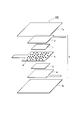
- FIG. 1 is a diagram illustrating a configuration example of a primary battery 100 according to the present embodiment. Its components are shown in (a), and its use state is shown in (b).
- the primary battery 100 is disposed between the positive electrode 1 and the positive electrode current collector 2, the negative electrode 3 and the negative electrode current collector 4 disposed to face the positive electrode 1 and the positive electrode current collector 2, and the positive electrode 1 and the negative electrode 3.
- the separator 5 includes a positive-side casing 7a and a negative-side casing 7b that are disposed so as to cover all of the components (1 to 5). All of the components (1 to 5, 7a, 7b) have a flat plate shape, and the relative or absolute sizes of the components are as shown in FIG.
- the constituent elements (1 to 5) are collectively referred to as a battery cell 6.
- the positive electrode or the negative electrode is a positive or negative electrode, and the electrode means a conductor or an element. Therefore, an element as an object (for example, an electrode body such as an electrode plate) is included in the word positive electrode or negative electrode. included.
- the separator 5 is made of a water-absorbing and insulating material that separates the positive electrode 1 and the negative electrode 3 and sucks up an electrolyte solution or water by capillary action, and a part other than the surface covered with the casings 7a and 7b is exposed to the atmosphere.
- a part other than the upper surface in contact with the positive electrode 1 and the positive electrode current collector 2 and the lower surface in contact with the negative electrode 3 and the negative electrode current collector 4 is exposed to the atmosphere.
- a strip-like portion extending in the left direction in the separator 5 indicates an exposed portion.
- a part of the separator 5 is exposed from the side opposite to the exposed portions of the positive electrode current collector 2 and the negative electrode current collector 4 described later. That is, the exposed portion of the separator 5 is provided on the side opposite to the terminals of the positive electrode 1 and the negative electrode 2.
- the positive electrode 1 and the positive electrode current collector 2 are positive electrodes of the primary battery 100.
- the positive electrode current collector 2 also includes a portion exposed to the atmosphere. Specifically, a part other than the lower surface in contact with the positive electrode 1 and the upper surface in contact with the positive electrode side housing 7a is exposed to the atmosphere. In FIG. 1, a strip-like portion extending in the right direction in the positive electrode current collector 2 indicates an exposed portion (a positive electrode terminal).
- the negative electrode 3 and the negative electrode current collector 4 are negative electrodes of the primary battery 100.
- the negative electrode current collector 4 also includes a portion exposed to the atmosphere. Specifically, a part other than the upper surface in contact with the negative electrode 3 and the lower surface in contact with the negative electrode side housing 7b is exposed to the atmosphere. In FIG. 1, a strip-like portion extending in the right direction in the negative electrode current collector 4 indicates an exposed portion (a negative electrode terminal).
- the electrolyte solution is sucked up by capillarity from the exposed portion of the separator 5 that is partially exposed outside the battery housings 7a and 7b, so that the electrolyte solution is placed inside the housings 7a and 7b.
- Electric power generation is started by bringing the taken-in electrolyte solution into contact with the positive electrode 1 and the negative electrode 3. That is, according to the primary battery 100 shown in FIG. 1, since the separator 5 that sucks up the electrolyte solution by capillary action is provided at the exposed portions from the casings 7a and 7b, a primary battery that is easy to handle and can generate electricity naturally can be provided.
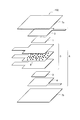
- FIG. 2 is a diagram illustrating another configuration example of the primary battery 100.
- the positive electrode 1 is a gas diffusion type positive electrode
- the negative electrode 3 is a negative electrode including magnesium
- the separator 5 is a separator including an electrolyte 8.
- the other configuration is the same as that of the primary battery 100 shown in FIG.
- FIG. 3 is a diagram illustrating another configuration example of the primary battery 100.
- the separator 5 is a layered separator in which a separator that does not include an electrolyte, a separator that includes an electrolyte 8, and a separator that does not include an electrolyte are sequentially stacked.
- the other configuration is the same as that of the primary battery 100 shown in FIG. 1 or FIG.
- the primary battery 100 shown in FIGS. 2 and 3 since the electrolyte 8 is contained in the separator 5 in advance, it is not necessary to suck up the electrolyte solution from the exposed portion of the separator 5, but only water (including natural water) is sucked up. You can start generating electricity. That is, according to the primary battery 100 shown in FIG. 2 and FIG. 3, since the separator 5 containing the electrolyte that sucks up water by capillary action at the exposed portions from the housings 7a and 7b is provided, the primary battery 100 that is easy to handle and capable of natural power generation is provided. Battery can be provided.
- the separator 5 may be an insulator having water absorption.
- a coffee filter, kitchen paper, plain paper, etc. can be used.
- a sheet of a material that is naturally decomposed while maintaining a certain strength such as a cellulose separator made of plant fibers, may be used.
- the casings 7a and 7b are not limited in material and shape as long as they can maintain the battery cell 6 inside.
- a laminate film type housing can be used.
- the casings 7a and 7b are made of a material that is naturally decomposed, any of a natural product type, a microbial type, and a chemical synthesis type may be used.
- it can be composed of materials such as polylactic acid, polycaprolactone, polyhydroxyalkanoate, polyglycolic acid, modified polyvinyl alcohol, casein, and modified starch.
- chemical synthesis systems such as plant-derived polylactic acid are preferred.
- casing 7a, 7b should just be a shape obtained by processing biodegradable plastics.
- a paper having a resin coating such as polyethylene used for milk cartons, an agar film, and the like can be used in addition to a commercially available biodegradable plastic film.
- the battery cell 6 can be sealed inside the casing by adhering the positive casing 7a and the negative casing 7b made of the above-mentioned materials at the peripheral edge of the battery cell 6.
- the bonding method include a method using a heat seal or an adhesive, and are not particularly limited.
- the casings 7a and 7b are difficult to adhere by heat sealing, it is preferable to use an adhesive.
- air holes are provided in the housings 7a and 7b in advance, or a part of the peripheral edge is opened without bonding, that is, a part of the wall surface of the housings 7a and 7b is connected to the inside. Air can be taken in by providing an air intake port.
- the shapes of the positive electrode 1, the positive electrode current collector 2, the negative electrode 3, the negative electrode current collector 4, the separator 5, and the casings 7a and 7b are not limited as long as the function for operating as a battery is not impaired.
- it can be used in a rectangular or circular sheet shape in a plan view, or a rolled shape.
- the positive electrode 1 and the negative electrode 3 will be described in detail.
- a conductive material generally used for the positive electrode of a metal-air battery can be used.
- a carbon material is mentioned, it is not limited to this.
- the positive electrode 1 can be produced by a known process in which carbon powder is molded with a binder. However, in the primary battery 100, it is important to generate a large amount of reaction sites inside the positive electrode 1, and the positive electrode 1 desirably has a high specific surface area.
- the positive electrode 1 is produced by molding carbon powder with a binder and pelletizing it, when the specific surface area is increased, the binding strength between the carbon powders is reduced and the structure is deteriorated, so that the structure is stable. It becomes difficult to discharge, and the discharge capacity may be reduced. Therefore, for example, by using a positive electrode having a three-dimensional network structure, it is not necessary to use a binder, and the discharge capacity can be increased.
- the positive electrode having such a three-dimensional network structure is preferably a co-continuum having a positive electrode (for example, carbon nanofiber described later) having an average pore diameter of 5 nm to 10 ⁇ m and a BET specific surface area of 20 m 2 / g or more. Furthermore, even if the positive electrode is subjected to a tensile stress or a compressive stress to cause a strain that expands or contracts to 80% or less of the length in the load direction of the positive electrode, the positive electrode does not exceed the elastic region and is restored to the shape before the stress application It is good.
- a positive electrode for example, carbon nanofiber described later
- the positive electrode 1 may carry a catalyst.
- the catalyst to be supported is not particularly limited, for example, a metal oxide composed of at least one metal of Fe, Mn, Zn, Cu, and Mo, or at least one metal of Ca, Fe, Mn, Zn, Cu, and Mo It is preferable that it is comprised from these.
- the metal is preferably Fe, Mn, or Zn, and is preferably an oxide composed of one of these or a composite oxide composed of two or more.
- manganese oxide (MnO 2 ) is preferable.
- the negative electrode 3 is composed of a negative electrode active material.
- the negative electrode active material is not particularly limited as long as it can be used as a negative electrode material for a primary battery.
- one or more kinds of metals selected from magnesium, zinc, aluminum, and iron, or an alloy mainly composed of one or more kinds of metals selected from these metals can be given.
- the negative electrode 3 can be formed by a known method. For example, a commercially available metal or alloy plate or foil can be formed into a predetermined shape and used.
- the electrolyte 8 may be any substance that can move metal ions and hydroxide ions between the positive electrode 1 and the negative electrode 3.
- the electrolyte 8 is not particularly limited.
- chlorides such as sodium chloride, potassium chloride, magnesium chloride, acetic acid, sodium acetate, potassium acetate, magnesium acetate anhydrous, acetates such as magnesium acetate tetrahydrate, citric acid, sodium citrate, potassium citrate Citrates such as magnesium citrate, carbonates such as sodium carbonate, potassium carbonate and magnesium carbonate, pyrophosphates such as sodium pyrophosphate, potassium pyrophosphate and magnesium pyrophosphate, sodium metaphosphate, potassium potassium metaphosphate, metaphosphate It is preferably composed of a metaphosphate such as magnesium, phosphoric acid, carbonic acid, HEPES (4- (2-hydroxyethyl) -1-piperazineethanesulfonic acid), and the like.
- the positive electrode current collector 2 and the negative electrode current collector 4 will be described.
- a known material can be used for the positive electrode current collector 2.
- a carbon sheet, carbon cloth, Fe, Cu, or Al plate may be used.
- a well-known thing can be used also about the negative electrode collector 4, when using a metal for a negative electrode, you may take out a terminal directly from the negative electrode 3 without using the negative electrode collector 4 outside.
- the electrode reaction of the positive electrode 1 and the negative electrode 3 will be described taking the case of the primary battery 100 using magnesium metal as the negative electrode as an example.
- the reaction represented by the formula (1) proceeds by contact of oxygen in the air and an electrolyte on the surface of the positive electrode 1 having conductivity. 1 / 2O 2 + H 2 O + 2e ⁇ ⁇ 2OH ⁇ (1)
- the reaction represented by the formula (2) proceeds in the negative electrode 3 in contact with the electrolyte supplied by the separator 5, and the magnesium constituting the negative electrode 3 releases electrons, and magnesium ions are contained in the electrolyte. Dissolve as Mg ⁇ Mg 2+ + 2e ⁇ (2)
- the reaction represented by the formula (1) proceeds on the surface of the positive electrode 1, so it is considered better to generate a large amount of reaction sites inside the positive electrode 1.
- the primary battery 100 made of a material that is naturally decomposed is naturally decomposed with time when used in a disposable device such as a soil moisture sensor, so it is necessary to recover the battery. Absent.
- the load on the environment is extremely low even when used in the natural world, such as in the forest or in the sea, in addition to soil.
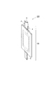
- FIG. 4 is a diagram illustrating a configuration example of the moisture sensor 200.
- the moisture sensor 200 includes a primary battery 100 and an alarm 9 connected between the positive electrode current collector 2 and the negative electrode current collector 4 of the primary battery 100.
- the configuration of the primary battery 100 is as described above.
- the positive electrode current collector 2 and the negative electrode current collector 4 that are spaced apart from each other without being in direct contact with each other serve as the electrodes of the moisture sensor 200, and the conduction between the positive electrode current collector 2 and the negative electrode current collector 4 Sense as existence. That is, it has an electrical configuration.
- the positive electrode current collector 2 and the negative electrode current collector 4 are insulated from each other.
- a notification operation is caused by the notification device 9.
- the alarm device 9 notifies the surroundings with a high-volume alarm sound, or notifies a remote device by transmitting radio waves.
- the alarm 9 is an example and may be any sensor having a moisture detection function.
- Example 1 In Example 1, the primary battery 100 of FIG. 1 using carbon nanofibers as the positive electrode 1 was produced.
- a commercially available carbon nanofiber sol [dispersion medium: water (H 2 O), 0.4 wt%, manufactured by Sigma-Aldrich] is placed in a test tube, and the test tube is immersed in liquid nitrogen for 30 minutes to form a carbon nanofiber. The sol was completely frozen. After completely freezing the carbon nanofiber sol, the frozen carbon nanofiber sol is taken out into an eggplant flask and dried in a vacuum of 10 Pa or less by a freeze dryer (manufactured by Tokyo Science Instruments Co., Ltd.) A stretchable co-continuum having a three-dimensional network structure containing carbon nanofibers was obtained.
- the linear carbon nanofiber fibers (the material of the positive electrode 1) are three-dimensionally formed in a continuous and integrated structure (a structure of a co-continuum).
- the branched, crimped, wavy, curled, and coiled fibers have a three-dimensional network structure and play a role like a spring, it can be understood that the co-continuum is stretchable. The inventor has confirmed that even if a tensile stress or a compressive stress is applied to the stretchable co-continuum obtained by the above production method, the shape is restored to the shape before the stress is applied.
- the positive electrode 1 was used by cutting the elastic co-continuum into a circular shape having a diameter of 17 mm with a punch.
- the positive electrode current collector 2 was made of carbon cloth and cut into a shape having a current collecting tab in a part of a 20 mm ⁇ 20 mm square.
- the negative electrode 3 was produced by cutting a commercially available magnesium alloy plate AZ31B (thickness 300 ⁇ m, made of Nippon Metal) into a shape having a current collecting tab in a part of a 20 mm ⁇ 20 mm square using scissors. In Example 1, instead of using the negative electrode current collector 4, the negative electrode 3 itself is provided with an exposed portion for current collection.
- AZ31B thickness 300 ⁇ m, made of Nippon Metal
- the separator 5 was a cellulosic separator for battery (manufactured by Nippon Kogyo Paper Industry Co., Ltd.) cut into a shape having a part that is exposed to the outside of the housing and sucks up water on a part of a 20 mm ⁇ 20 mm square.
- a film sheet ecolog (made by Mitsubishi Plastics) was used for the casings 7a and 7b. This sheet was cut into a plan view of 30 mm ⁇ 30 mm to produce two cut sheets, one of which was a positive-side casing 7a and the other was a negative-side casing 7b.
- the negative electrode 3 and the separator 5 are disposed on the negative-side housing 7b, and the positive electrode 1, the positive electrode current collector 2, and the positive-side housing 7a are sequentially covered thereon, and the peripheral edges of the two housings 7a and 7b.
- the part was heat-sealed at 130 ° C. using a sealer and sealed. At this time, air holes were provided by not sealing a part (for example, about 10 mm) of the peripheral portions of the casings 7a and 7b.
- the weight of the primary battery 100 thus obtained was about 0.5 g.
- the battery performance of the produced primary battery 100 was measured.
- the electrolyte solution a solution in which sodium chloride (NaCl, manufactured by Kanto Chemical Co., Ltd.) was dissolved in pure water at a concentration of 1 mol / L was used.
- FIG. 6 shows a voltage change between the positive electrode 1 and the negative electrode 3 when a 1 mol / l NaCl aqueous solution is sucked as an electrolyte solution from the exposed portion of the separator 5 exposed outside the casing.
- the electrolyte solution was sucked up from the separator 5, the voltage rose, and a stable voltage was obtained in about 200 seconds from the start of the suction. The voltage at this time was about 1.6V.
- a discharge test was performed.
- a commercially available charge / discharge measurement system (SD8 charge / discharge system manufactured by Hokuto Denko Co., Ltd.) was used, and a current density per effective area of the positive electrode 1 of 2.0 mA / cm 2 was applied to open circuit. Measurement was performed until the battery voltage dropped from the voltage to 0V.
- the discharge test of the primary battery 100 was performed while supplying an electrolyte solution to the exposed portion of the separator 5 exposed from the housings 7a and 7b in a constant temperature bath at 25 ° C. (atmosphere is a normal living environment).
- the discharge capacity was expressed as a value (mAh / g) per weight of the positive electrode 1 made of a co-continuum.
- the first discharge curve in Example 1 is shown in FIG. As shown in FIG. 7, the average discharge voltage is about 1.15 V, and the discharge capacity is about 1050 mAh / g.
- Example 2 In Example 2, a case where a catalyst is supported on the positive electrode 1 of Example 1 (a stretchable co-continuum having a three-dimensional network structure including carbon nanofibers) will be described.
- manganese oxide (MnO 2 ) is supported as a representative of the catalyst.
- arbitrary oxide can be carry
- Example 1 A commercially available manganese (II) chloride tetrahydrate (MnCl 2 .4H 2 O; manufactured by Kanto Chemical Co., Ltd.) was dissolved in distilled water and produced by the method of Example 1 “having a three-dimensional network structure including carbon nanofibers” It was impregnated with a stretchable co-continuum. Subsequently, aqueous ammonia (28%) was gradually added dropwise until pH 7.0 and neutralized to precipitate manganese hydroxide. The precipitate was repeatedly washed with distilled water five times so that no chlorine remained.
- II manganese
- the obtained manganese hydroxide-carrying carbon nanofibers were heat-treated at 500 ° C. for 6 hours in an argon atmosphere to produce carbon nanofibers carrying manganese oxide (MnO 2 ). And the produced manganese oxide carrying
- the production of the primary battery 100 and the charge / discharge test method are the same as in Example 1.
- a discharge test was performed.
- the average discharge voltage of the primary battery 100 was about 1.32 V, and the discharge capacity was about 1700 mAh / g.
- the average discharge voltage was higher than that of Example 1 in which manganese oxide (MnO 2 ) was not supported as a catalyst, and the discharge capacity was also large.
- Example 3 In Example 3, the configuration of the primary battery 100 was changed to the configuration of FIG. 2, and the charge / discharge test was performed while supplying the electrolyte solution from the exposed portion of the separator 5 as in Example 2.
- the manufacturing method of the primary battery 100 in Example 3 is the same as that in Example 2.
- the separator 5 contains an electrolyte 8.
- the electrolyte-containing separator 5 is obtained by immersing NaCl in the electrolyte solution for 30 minutes to support NaCl as an electrolyte and naturally drying in the air for 1 hour.
- Example 2 After discharging tap water from the exposed portion of the separator 5 exposed outside the housing, a discharge test was performed while supplying an electrolyte solution to the exposed portion.
- the average discharge voltage of the primary battery 100 was about 1.25 V
- the discharge capacity was about 1470 mAh / g
- both the discharge voltage and the discharge capacity were somewhat lower than in Example 2.
- Example 4 In Example 4, the configuration of the primary battery 100 was changed to the configuration of FIG. 3, and the charge / discharge test was performed while supplying the electrolyte solution from the exposed portion of the separator 5 as in Example 2.
- the manufacturing method of the primary battery 100 in Example 4 is the same as that in Example 2.
- the separator 5 has a laminated structure. Specifically, the electrolyte-containing separator 5 obtained by supporting NaCl, which is an electrolyte, by immersing in an electrolyte solution for 30 minutes and naturally drying in the air for 1 hour is divided into two electrolyte-free separators facing each other. It has a three-layer structure sandwiched between.
- Example 2 After discharging tap water from the exposed portion of the separator 5 exposed outside the housing, a discharge test was performed while supplying an electrolyte solution to the exposed portion.
- the average discharge voltage of the primary battery 100 was about 1.30 V
- the discharge capacity was about 1690 mAh / g
- both the discharge voltage and the discharge capacity were the same as those in Example 2.
- Example 5 the metals used for the negative electrode 3 were respectively a commercially available metal zinc plate (thickness 200 ⁇ m, manufactured by Nilaco) (Example 5) and an aluminum plate (thickness 200 ⁇ m, manufactured by Nilaco) (Example 6). ), An iron plate (thickness 200 ⁇ m, manufactured by Niraco) (Example 7).
- the primary battery 100 was produced by the same method as in Example 2, and the discharge test was performed while supplying the electrolyte solution to the exposed portion of the separator 5. Both were confirmed to operate as the primary battery 100. The measurement results are shown in FIG. 8 together with Examples 1 to 4.
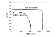
- Comparative Example 1 For reference, a discharge test result by a known general battery cell structure is disclosed as a comparative example.
- the shape of the separator 5 is changed, and the separator 5 is placed in a casing in a state where the separator 5 is dipped in an electrolytic solution and wetted in advance, and sealed. The rest is the same as in the second embodiment.
- the separator 5 was a cellulosic separator for battery (manufactured by Nippon Kogyo Paper Industry Co., Ltd.) cut into a 20 mm ⁇ 20 mm square. There is no exposed portion to the outside of the housing as in this embodiment.
- the negative electrode 3 and the separator 5 are arranged on the negative electrode side housing 7b, and the positive electrode 1, the positive electrode current collector 2, and the positive electrode side housing 7a are sequentially covered on the negative electrode 3 and the separator 5 on the periphery of the two cases 7a and 7b.
- Three sides were heat-sealed at 130 ° C. using a sealer.
- the electrolyte solution was poured into this to wet the separator 5, and the remaining one side was heat sealed and sealed. At this time, an air hole was provided by not sealing only a part (about 10 mm) of the peripheral edge of the casings 7a and 7b.
- the primary battery 100 manufactured using the separator previously wetted with a certain amount of electrolyte solution has an average discharge voltage of about 1.27 V, a discharge capacity of about 130 mAh / g, and a discharge voltage and a discharge capacity. Both were lower than in Example 2.
- Comparative Example 2 In Comparative Example 2, the shape of the separator 5 is changed, and only a part (about 10 mm) of the peripheral portions of the casings 7a and 7b is not sealed, so that an air hole is provided and sealed, and then an electrolytic solution is injected. The rest is the same as in the second embodiment.
- the negative electrode 3 and the separator 5 are arranged on the negative electrode side housing 7b, and the positive electrode 1, the positive electrode current collector 2, and the positive electrode side housing 7a are sequentially covered on the negative electrode 3 and the separator 5 on the periphery of the two cases 7a and 7b.
- Four sides were heat-sealed at 130 ° C. using a sealer. At this time, an air hole was provided by not sealing only a part (about 10 mm) of the peripheral edge of the casings 7a and 7b.
- the primary battery 100 produced by injecting a sufficient amount of electrolyte solution (3 mL) with a dropper from the air hole has an average discharge voltage of about 0.71 V, a discharge capacity of about 510 mAh / g, Both discharge capacities were significantly lower than in Example 2.
- the primary battery 100 using magnesium metal for the negative electrode 3 of the present embodiment shows a discharge capacity of about 1000 mAh / g or more even when no catalyst is supported, and the average discharge voltage is higher when the catalyst is supported. It was confirmed that the discharge capacity was about 1.3V or more and the discharge capacity was about 1700 mAh / g or more. Moreover, it was confirmed that metals other than magnesium (for example, zinc, aluminum, iron) also operate as a battery.
- the discharge capacity was as low as about 130 mA / g.
- the primary battery 100 according to the present embodiment is supplied from the exposed portion of the separator 5 without any shortage of the electrolyte solution, but in the case of the configuration as in Comparative Example 1, the amount of the electrolyte solution is not sufficient. it is conceivable that.
- both the discharge voltage and the discharge capacity were significantly lower than those in Example 2. Since both surfaces of the negative electrode 3 and the positive electrode 1 are constantly in contact with the electrolyte solution, corrosion of the negative electrode 1 is observed, and a sufficient amount of the electrolyte solution is obtained from the air holes provided in part of the peripheral portions of the casings 7a and 7b. Since (3 mL) was injected, both the separator-side surface and the housing-side surface of the positive electrode 1 were covered with the electrolytic solution, and the surface in contact with air was reduced from that in Example 2, thereby reducing the discharge capacity. It is thought that. Moreover, about the fall of an average voltage, it is thought that it is because the contact with the positive electrode 1, the separator 5, and the negative electrode 3 was not favorable.
- the primary battery 100 according to the present embodiment has excellent performance in both voltage and discharge capacity.
- the separator 5 that sucks up the electrolyte solution by capillary action at the exposed portion from the battery housing is provided, there is no self-discharge before use, and the electrolyte solution required at the time of use. Therefore, it is possible to provide a primary battery that is easy to handle and capable of natural power generation with a small amount of liquid, without fear of leakage.
- the electrolyte-containing separator 5 that sucks up water by capillary action at the exposed portion from the battery housing is provided, there is no self-discharge before use, and a small amount of water required for use can be obtained. It is possible to provide a primary battery that is easy to handle and can generate electricity without worrying about leakage.
- the electrolyte solution is not contained inside the battery case before use, side reactions such as corrosion of the negative electrode 3 in the primary battery 100 can be suppressed and can be easily handled.
- the electrolyte solution or water is sucked up and discharged at the time of use, so that the discharge capacity of the primary battery 100 can be increased.
- the primary battery 100 of the present invention is not limited to the configuration described in the present embodiment, and many modifications and changes are made by those having ordinary knowledge in the art within the technical idea of the present invention. It is clear that combinations can be implemented.
Landscapes
- Chemical & Material Sciences (AREA)
- Chemical Kinetics & Catalysis (AREA)
- Electrochemistry (AREA)
- General Chemical & Material Sciences (AREA)
- Engineering & Computer Science (AREA)
- Manufacturing & Machinery (AREA)
- Primary Cells (AREA)
- Hybrid Cells (AREA)
- Cell Separators (AREA)
- Filling, Topping-Up Batteries (AREA)
- Battery Electrode And Active Subsutance (AREA)
Priority Applications (4)
| Application Number | Priority Date | Filing Date | Title |
|---|---|---|---|
| JP2018551644A JP6830109B2 (ja) | 2016-11-16 | 2017-11-14 | 水分センサ |
| US16/338,950 US11374219B2 (en) | 2016-11-16 | 2017-11-14 | Primary battery and moisture sensor |
| CN201780064888.7A CN109845006B (zh) | 2016-11-16 | 2017-11-14 | 一次电池和水分传感器 |
| EP17871676.7A EP3544100B1 (en) | 2016-11-16 | 2017-11-14 | Moisture sensor |
Applications Claiming Priority (2)
| Application Number | Priority Date | Filing Date | Title |
|---|---|---|---|
| JP2016-222906 | 2016-11-16 | ||
| JP2016222906 | 2016-11-16 |
Publications (1)
| Publication Number | Publication Date |
|---|---|
| WO2018092773A1 true WO2018092773A1 (ja) | 2018-05-24 |
Family
ID=62145553
Family Applications (1)
| Application Number | Title | Priority Date | Filing Date |
|---|---|---|---|
| PCT/JP2017/040935 WO2018092773A1 (ja) | 2016-11-16 | 2017-11-14 | 一次電池及び水分センサ |
Country Status (5)
| Country | Link |
|---|---|
| US (1) | US11374219B2 (zh) |
| EP (1) | EP3544100B1 (zh) |
| JP (1) | JP6830109B2 (zh) |
| CN (1) | CN109845006B (zh) |
| WO (1) | WO2018092773A1 (zh) |
Cited By (9)
| Publication number | Priority date | Publication date | Assignee | Title |
|---|---|---|---|---|
| NO20180811A1 (en) * | 2018-06-12 | 2019-12-13 | Fyster As | A moisture detector and a method for making a moisture detector |
| IT201800009252A1 (it) * | 2018-10-08 | 2020-04-08 | Bluethink Spa | Cella a combustibile smaltibile ad alta temperatura e apparato comprendente detta cella |
| JP2021156672A (ja) * | 2020-03-26 | 2021-10-07 | 藤倉コンポジット株式会社 | 液検知センサ |
| JP2021156670A (ja) * | 2020-03-26 | 2021-10-07 | 藤倉コンポジット株式会社 | 液検知センサ |
| WO2021210337A1 (ja) * | 2020-04-15 | 2021-10-21 | 藤倉コンポジット株式会社 | 液検知センサ |
| WO2022085797A1 (ja) * | 2020-10-23 | 2022-04-28 | トライポッド・デザイン株式会社 | 発電素子及びセンサ |
| JP7142402B1 (ja) | 2022-07-18 | 2022-09-27 | 東友株式会社 | 電池用筐体及びそれを備えた電池装置 |
| WO2022249329A1 (ja) * | 2021-05-26 | 2022-12-01 | 日本電信電話株式会社 | 冠水センサおよび通知システム |
| JP7181660B1 (ja) | 2022-07-18 | 2022-12-01 | 東友株式会社 | 電池装置 |
Families Citing this family (30)
| Publication number | Priority date | Publication date | Assignee | Title |
|---|---|---|---|---|
| US10531977B2 (en) | 2014-04-17 | 2020-01-14 | Coloplast A/S | Thermoresponsive skin barrier appliances |
| WO2019120435A1 (en) | 2017-12-22 | 2019-06-27 | Coloplast A/S | Ostomy appliance with selective sensor points and related methods |
| US12064369B2 (en) | 2017-12-22 | 2024-08-20 | Coloplast A/S | Processing schemes for an ostomy system, monitor device for an ostomy appliance and related methods |
| US10799385B2 (en) | 2017-12-22 | 2020-10-13 | Coloplast A/S | Ostomy appliance with layered base plate |
| US11628084B2 (en) | 2017-12-22 | 2023-04-18 | Coloplast A/S | Sensor assembly part and a base plate for a medical appliance and a device for connecting to a base plate or a sensor assembly part |
| JP2021508269A (ja) * | 2017-12-22 | 2021-03-04 | コロプラスト アクティーゼルスカブ | オストミー装具用のベースプレート及びベースプレート用のセンサ組立体部分、並びに、ベースプレート及びセンサ組立体部分を製造するための方法 |
| US10849781B2 (en) | 2017-12-22 | 2020-12-01 | Coloplast A/S | Base plate for an ostomy appliance |
| US11607334B2 (en) | 2017-12-22 | 2023-03-21 | Coloplast A/S | Base plate for a medical appliance, a monitor device and a system for a medical appliance |
| JP7348184B2 (ja) | 2017-12-22 | 2023-09-20 | コロプラスト アクティーゼルスカブ | オストミーベースプレート及びセンサ組立体部分のためのヒンジを有する結合部 |
| US10500084B2 (en) | 2017-12-22 | 2019-12-10 | Coloplast A/S | Accessory devices of an ostomy system, and related methods for communicating leakage state |
| EP3729453A1 (en) | 2017-12-22 | 2020-10-28 | Coloplast A/S | Calibration methods for ostomy appliance tools |
| WO2019120449A1 (en) | 2017-12-22 | 2019-06-27 | Coloplast A/S | Ostomy system and monitor device with angular leakage detection |
| US11612508B2 (en) | 2017-12-22 | 2023-03-28 | Coloplast A/S | Sensor assembly part for a medical appliance and a method for manufacturing a sensor assembly part |
| US11865029B2 (en) | 2017-12-22 | 2024-01-09 | Coloplast A/S | Monitor device of a medical system having a connector for coupling to both a base plate and an accessory device |
| EP3729456B1 (en) | 2017-12-22 | 2021-12-01 | Coloplast A/S | Monitor device of an ostomy system and associated method for operating a monitor device |
| US11590015B2 (en) | 2017-12-22 | 2023-02-28 | Coloplast A/S | Sensor assembly part and a base plate for a medical appliance and a method for manufacturing a sensor assembly part and a base plate |
| US11534323B2 (en) | 2017-12-22 | 2022-12-27 | Coloplast A/S | Tools and methods for placing a medical appliance on a user |
| EP3727246B1 (en) | 2017-12-22 | 2024-07-10 | Coloplast A/S | Tools and methods for cutting holes in an ostomy appliance |
| LT3727219T (lt) | 2017-12-22 | 2023-09-11 | Coloplast A/S | Drėgmės aptikimo pagrindo plokštė ostomijos prietaisui ir drėgmės sklidimo pagrindo plokštėje ir (arba) jutiklių montavimo dalyje nustatymo sistema |
| WO2019120429A1 (en) | 2017-12-22 | 2019-06-27 | Coloplast A/S | Data collection schemes for an ostomy appliance and related methods |
| WO2019120443A1 (en) | 2017-12-22 | 2019-06-27 | Coloplast A/S | Sensor assembly part and a base plate for an ostomy appliance and a method for manufacturing a base plate or a sensor assembly part |
| JP7282781B2 (ja) | 2017-12-22 | 2023-05-29 | コロプラスト アクティーゼルスカブ | 角度範囲漏出検出機能を備えるオストミー装具 |
| CN111432756B (zh) | 2017-12-22 | 2022-07-29 | 科洛普拉斯特公司 | 具有泄漏传感器的造口术系统的底板和传感器组件部 |
| US11559423B2 (en) | 2017-12-22 | 2023-01-24 | Coloplast A/S | Medical appliance system, monitor device, and method of monitoring a medical appliance |
| WO2019161863A1 (en) | 2018-02-20 | 2019-08-29 | Coloplast A/S | Accessory devices of an ostomy system, and related methods for changing an ostomy appliance based on future operating state |
| EP3755282B1 (en) | 2018-02-20 | 2024-05-08 | Coloplast A/S | Sensor assembly part and a base plate for an ostomy appliance and a device for connecting to a base plate and/or a sensor assembly part |
| WO2019174697A1 (en) | 2018-03-15 | 2019-09-19 | Coloplast A/S | Apparatus and methods for navigating ostomy appliance user to changing room |
| WO2020125907A1 (en) | 2018-12-20 | 2020-06-25 | Coloplast A/S | Ostomy condition classification with image data transformation, devices and related methods |
| US11612512B2 (en) * | 2019-01-31 | 2023-03-28 | Coloplast A/S | Moisture detecting base plate for an ostomy appliance and a system for determining moisture propagation in a base plate and/or a sensor assembly part |
| KR102532519B1 (ko) | 2021-02-25 | 2023-05-12 | 중앙대학교 산학협력단 | 피부 땀을 이용한 자가발전 장치 및 이를 이용한 센서 유닛 |
Citations (12)
| Publication number | Priority date | Publication date | Assignee | Title |
|---|---|---|---|---|
| JPS634664U (zh) * | 1986-06-26 | 1988-01-13 | ||
| JPH07130406A (ja) * | 1993-10-29 | 1995-05-19 | Koa Oil Co Ltd | 空気電池 |
| JPH09183400A (ja) * | 1995-12-28 | 1997-07-15 | Mitsubishi Heavy Ind Ltd | 投下着水式海難救助用ゴムボート |
| JP2003151633A (ja) * | 2001-08-17 | 2003-05-23 | Samsung Sdi Co Ltd | ゾル状の高分子電解質及びこれを採用したリチウム電池 |
| JP2003257509A (ja) * | 2002-03-06 | 2003-09-12 | Toin Gakuen | 光発電体シート、それを用いた太陽光発電用ユニット及び発電装置 |
| JP2004158453A (ja) * | 2002-11-02 | 2004-06-03 | Samsung Sdi Co Ltd | 無機保護膜を有するセパレータ及びこれを採用したリチウム電池 |
| WO2007116872A1 (ja) * | 2006-04-03 | 2007-10-18 | Tsc Co., Ltd. | 水発電用合金、前記合金を用いる水発電装置、及び水発電方法 |
| JP2010073338A (ja) * | 2008-09-16 | 2010-04-02 | Kankyo Kagaku Kenkyusho:Kk | 金属燃料電池 |
| JP2014196919A (ja) * | 2013-03-29 | 2014-10-16 | タツタ電線株式会社 | 液体検知センサー |
| JP2014203810A (ja) * | 2013-04-10 | 2014-10-27 | 三嶋電子株式会社 | 水電池 |
| JP2015032379A (ja) * | 2013-07-31 | 2015-02-16 | 株式会社ギャラキシー | 電池のセパレータ |
| JP2015201441A (ja) * | 2014-04-02 | 2015-11-12 | 大森 弘一郎 | マグネシウムカード電池。 |
Family Cites Families (14)
| Publication number | Priority date | Publication date | Assignee | Title |
|---|---|---|---|---|
| DE4305560A1 (de) * | 1993-02-24 | 1994-08-25 | Varta Batterie | Gasdicht verschlossener Nickel/Hydrid-Akkumulator |
| US7081142B1 (en) * | 1999-11-23 | 2006-07-25 | Sion Power Corporation | Methods of preparing electrochemical cells |
| GB2374419B (en) * | 2001-03-09 | 2004-12-29 | Zellweger Analytics Ltd | Electrochemical gas sensor |
| EP1244168A1 (en) * | 2001-03-20 | 2002-09-25 | Francois Sugnaux | Mesoporous network electrode for electrochemical cell |
| JP4317099B2 (ja) | 2004-08-12 | 2009-08-19 | 日本電信電話株式会社 | 漏水センサーおよび漏水検出システム |
| KR100690015B1 (ko) | 2004-11-09 | 2007-03-08 | 주식회사 엘지생활건강 | 개방형 박막 전지 |
| US7799466B2 (en) * | 2005-12-16 | 2010-09-21 | Hirate Energy Technology Corporation Ltd. | Lead acid battery having lightly gelled electrolyte |
| FI121611B (fi) * | 2007-02-06 | 2011-01-31 | Enfucell Oy | Ohutparisto ja menetelmä ohutpariston valmistamiseksi |
| US20100203394A1 (en) * | 2009-02-06 | 2010-08-12 | In Tae Bae | Thin metal-air batteries |
| EP2410321B1 (de) * | 2010-07-15 | 2017-03-08 | Hach Lange GmbH | Wasseranalyse-Sensorelektrode |
| CN103181016B (zh) * | 2010-09-13 | 2016-06-22 | 加利福尼亚大学董事会 | 离子凝胶电解质、储能设备及其制造方法 |
| JP5906698B2 (ja) * | 2011-12-01 | 2016-04-20 | 株式会社Gsユアサ | 非水電解質二次電池 |
| JP2015197392A (ja) | 2014-04-02 | 2015-11-09 | ホシデン株式会社 | 電源を兼ね備えた液体有無検出機器及びそれを備えた空気改良機器 |
| KR101671108B1 (ko) * | 2015-04-23 | 2016-10-31 | 울산대학교 산학협력단 | 산화아연을 함유하는 음극활물질 및 이를 사용한 아연공기 이차전지 |
-
2017
- 2017-11-14 WO PCT/JP2017/040935 patent/WO2018092773A1/ja unknown
- 2017-11-14 US US16/338,950 patent/US11374219B2/en active Active
- 2017-11-14 JP JP2018551644A patent/JP6830109B2/ja active Active
- 2017-11-14 EP EP17871676.7A patent/EP3544100B1/en active Active
- 2017-11-14 CN CN201780064888.7A patent/CN109845006B/zh active Active
Patent Citations (12)
| Publication number | Priority date | Publication date | Assignee | Title |
|---|---|---|---|---|
| JPS634664U (zh) * | 1986-06-26 | 1988-01-13 | ||
| JPH07130406A (ja) * | 1993-10-29 | 1995-05-19 | Koa Oil Co Ltd | 空気電池 |
| JPH09183400A (ja) * | 1995-12-28 | 1997-07-15 | Mitsubishi Heavy Ind Ltd | 投下着水式海難救助用ゴムボート |
| JP2003151633A (ja) * | 2001-08-17 | 2003-05-23 | Samsung Sdi Co Ltd | ゾル状の高分子電解質及びこれを採用したリチウム電池 |
| JP2003257509A (ja) * | 2002-03-06 | 2003-09-12 | Toin Gakuen | 光発電体シート、それを用いた太陽光発電用ユニット及び発電装置 |
| JP2004158453A (ja) * | 2002-11-02 | 2004-06-03 | Samsung Sdi Co Ltd | 無機保護膜を有するセパレータ及びこれを採用したリチウム電池 |
| WO2007116872A1 (ja) * | 2006-04-03 | 2007-10-18 | Tsc Co., Ltd. | 水発電用合金、前記合金を用いる水発電装置、及び水発電方法 |
| JP2010073338A (ja) * | 2008-09-16 | 2010-04-02 | Kankyo Kagaku Kenkyusho:Kk | 金属燃料電池 |
| JP2014196919A (ja) * | 2013-03-29 | 2014-10-16 | タツタ電線株式会社 | 液体検知センサー |
| JP2014203810A (ja) * | 2013-04-10 | 2014-10-27 | 三嶋電子株式会社 | 水電池 |
| JP2015032379A (ja) * | 2013-07-31 | 2015-02-16 | 株式会社ギャラキシー | 電池のセパレータ |
| JP2015201441A (ja) * | 2014-04-02 | 2015-11-12 | 大森 弘一郎 | マグネシウムカード電池。 |
Non-Patent Citations (1)
| Title |
|---|
| See also references of EP3544100A4 * |
Cited By (14)
| Publication number | Priority date | Publication date | Assignee | Title |
|---|---|---|---|---|
| NO20180811A1 (en) * | 2018-06-12 | 2019-12-13 | Fyster As | A moisture detector and a method for making a moisture detector |
| NO346810B1 (en) * | 2018-06-12 | 2023-01-16 | Fyster As | A moisture detector and a method for making a moisture detector |
| IT201800009252A1 (it) * | 2018-10-08 | 2020-04-08 | Bluethink Spa | Cella a combustibile smaltibile ad alta temperatura e apparato comprendente detta cella |
| JP2021156670A (ja) * | 2020-03-26 | 2021-10-07 | 藤倉コンポジット株式会社 | 液検知センサ |
| JP2021156672A (ja) * | 2020-03-26 | 2021-10-07 | 藤倉コンポジット株式会社 | 液検知センサ |
| JP7437846B2 (ja) | 2020-03-26 | 2024-02-26 | 藤倉コンポジット株式会社 | 液検知センサ |
| JP7437845B2 (ja) | 2020-03-26 | 2024-02-26 | 藤倉コンポジット株式会社 | 液検知センサ |
| WO2021210337A1 (ja) * | 2020-04-15 | 2021-10-21 | 藤倉コンポジット株式会社 | 液検知センサ |
| WO2022085797A1 (ja) * | 2020-10-23 | 2022-04-28 | トライポッド・デザイン株式会社 | 発電素子及びセンサ |
| WO2022249329A1 (ja) * | 2021-05-26 | 2022-12-01 | 日本電信電話株式会社 | 冠水センサおよび通知システム |
| JP7142402B1 (ja) | 2022-07-18 | 2022-09-27 | 東友株式会社 | 電池用筐体及びそれを備えた電池装置 |
| JP7181660B1 (ja) | 2022-07-18 | 2022-12-01 | 東友株式会社 | 電池装置 |
| JP2024012233A (ja) * | 2022-07-18 | 2024-01-30 | 東友株式会社 | 電池用筐体及びそれを備えた電池装置 |
| JP2024012234A (ja) * | 2022-07-18 | 2024-01-30 | 東友株式会社 | 電池装置 |
Also Published As
| Publication number | Publication date |
|---|---|
| US11374219B2 (en) | 2022-06-28 |
| EP3544100A1 (en) | 2019-09-25 |
| JPWO2018092773A1 (ja) | 2019-06-27 |
| US20200395610A1 (en) | 2020-12-17 |
| EP3544100B1 (en) | 2022-06-22 |
| JP6830109B2 (ja) | 2021-02-17 |
| CN109845006B (zh) | 2022-03-11 |
| CN109845006A (zh) | 2019-06-04 |
| EP3544100A4 (en) | 2020-08-12 |
Similar Documents
| Publication | Publication Date | Title |
|---|---|---|
| WO2018092773A1 (ja) | 一次電池及び水分センサ | |
| JP6070671B2 (ja) | 空気電池 | |
| JP7025644B2 (ja) | 金属空気電池及び空気極製造方法 | |
| EP2782185A1 (en) | Zinc-air secondary battery | |
| WO2011087089A1 (ja) | 空気電池、空気電池スタック | |
| CN106471649B (zh) | 二次电化学电池和充电方法 | |
| JP6711915B2 (ja) | 電池およびその正極の製造方法 | |
| JP6951623B2 (ja) | マグネシウム水電池およびその正極の製造方法 | |
| JP5782170B2 (ja) | 空気電池用空気極及び空気電池 | |
| CN104137325A (zh) | 金属氧电池 | |
| WO2017187888A1 (ja) | リチウム空気電池の負極複合体構造 | |
| JP7068585B2 (ja) | バイポーラ型金属空気電池、空気極製造方法、及び、集電体製造方法 | |
| JP7277831B2 (ja) | 空気電池および検知装置 | |
| WO2023233522A1 (ja) | マグネシウム空気電池およびその製造方法 | |
| WO2024150394A1 (ja) | マグネシウム空気電池およびその製造方法 | |
| JP2013069493A (ja) | ラミネート型空気電池の製造方法 | |
| US10651445B2 (en) | Electrode with cellulose acetate separator system | |
| JP7412143B2 (ja) | 亜鉛電池用負極 | |
| US20230395873A1 (en) | Iron Zinc Battery | |
| US20230387379A1 (en) | Primary Battery | |
| WO2021111515A1 (ja) | 金属空気電池、金属空気電池の正極の製造方法および金属空気電池の製造方法 | |
| JP5285134B2 (ja) | リチウムイオン酸素電池 | |
| JP5393747B2 (ja) | 金属酸素電池 | |
| JP2019029248A (ja) | リチウム空気電池及びその製造方法 |
Legal Events
| Date | Code | Title | Description |
|---|---|---|---|
| 121 | Ep: the epo has been informed by wipo that ep was designated in this application |
Ref document number: 17871676 Country of ref document: EP Kind code of ref document: A1 |
|
| ENP | Entry into the national phase |
Ref document number: 2018551644 Country of ref document: JP Kind code of ref document: A |
|
| NENP | Non-entry into the national phase |
Ref country code: DE |
|
| ENP | Entry into the national phase |
Ref document number: 2017871676 Country of ref document: EP Effective date: 20190617 |