US11559423B2 - Medical appliance system, monitor device, and method of monitoring a medical appliance - Google Patents
Medical appliance system, monitor device, and method of monitoring a medical appliance Download PDFInfo
- Publication number
- US11559423B2 US11559423B2 US16/954,521 US201816954521A US11559423B2 US 11559423 B2 US11559423 B2 US 11559423B2 US 201816954521 A US201816954521 A US 201816954521A US 11559423 B2 US11559423 B2 US 11559423B2
- Authority
- US
- United States
- Prior art keywords
- operating state
- base plate
- parameter data
- data
- electrode
- Prior art date
- Legal status (The legal status is an assumption and is not a legal conclusion. Google has not performed a legal analysis and makes no representation as to the accuracy of the status listed.)
- Active, expires
Links
- 238000000034 method Methods 0.000 title claims abstract description 36
- 238000012544 monitoring process Methods 0.000 title claims abstract description 10
- 230000003628 erosive effect Effects 0.000 claims abstract description 35
- 238000012545 processing Methods 0.000 claims abstract description 32
- 230000001154 acute effect Effects 0.000 claims abstract description 10
- 230000008859 change Effects 0.000 claims description 25
- 239000012790 adhesive layer Substances 0.000 description 183
- 230000006870 function Effects 0.000 description 71
- 230000001070 adhesive effect Effects 0.000 description 59
- 239000000853 adhesive Substances 0.000 description 57
- 239000010410 layer Substances 0.000 description 45
- 238000003032 molecular docking Methods 0.000 description 43
- 230000008878 coupling Effects 0.000 description 42
- 238000010168 coupling process Methods 0.000 description 42
- 238000005859 coupling reaction Methods 0.000 description 42
- 230000000873 masking effect Effects 0.000 description 33
- 239000000203 mixture Substances 0.000 description 28
- 239000000416 hydrocolloid Substances 0.000 description 23
- 230000008961 swelling Effects 0.000 description 22
- 239000004020 conductor Substances 0.000 description 11
- -1 tackifiers Substances 0.000 description 10
- 230000002087 whitening effect Effects 0.000 description 10
- 239000000463 material Substances 0.000 description 9
- OKTJSMMVPCPJKN-UHFFFAOYSA-N Carbon Chemical compound [C] OKTJSMMVPCPJKN-UHFFFAOYSA-N 0.000 description 8
- 239000004433 Thermoplastic polyurethane Substances 0.000 description 8
- 229920001083 polybutene Polymers 0.000 description 8
- 229920002803 thermoplastic polyurethane Polymers 0.000 description 8
- VSKJLJHPAFKHBX-UHFFFAOYSA-N 2-methylbuta-1,3-diene;styrene Chemical compound CC(=C)C=C.C=CC1=CC=CC=C1.C=CC1=CC=CC=C1 VSKJLJHPAFKHBX-UHFFFAOYSA-N 0.000 description 7
- 229920002367 Polyisobutene Polymers 0.000 description 7
- 230000009471 action Effects 0.000 description 7
- XLYOFNOQVPJJNP-UHFFFAOYSA-N water Substances O XLYOFNOQVPJJNP-UHFFFAOYSA-N 0.000 description 7
- 229920001577 copolymer Polymers 0.000 description 6
- 230000007423 decrease Effects 0.000 description 6
- 238000007789 sealing Methods 0.000 description 6
- 210000004243 sweat Anatomy 0.000 description 6
- 229920002725 thermoplastic elastomer Polymers 0.000 description 6
- 238000010586 diagram Methods 0.000 description 5
- 230000000694 effects Effects 0.000 description 5
- 239000012530 fluid Substances 0.000 description 5
- 230000037380 skin damage Effects 0.000 description 5
- VYPSYNLAJGMNEJ-UHFFFAOYSA-N Silicium dioxide Chemical compound O=[Si]=O VYPSYNLAJGMNEJ-UHFFFAOYSA-N 0.000 description 4
- PPBRXRYQALVLMV-UHFFFAOYSA-N Styrene Natural products C=CC1=CC=CC=C1 PPBRXRYQALVLMV-UHFFFAOYSA-N 0.000 description 4
- 230000008901 benefit Effects 0.000 description 4
- 239000000919 ceramic Substances 0.000 description 4
- 238000004891 communication Methods 0.000 description 4
- 230000001419 dependent effect Effects 0.000 description 4
- 229920006132 styrene block copolymer Polymers 0.000 description 4
- 229920006344 thermoplastic copolyester Polymers 0.000 description 4
- 229920002397 thermoplastic olefin Polymers 0.000 description 4
- 229920006345 thermoplastic polyamide Polymers 0.000 description 4
- 229920006342 thermoplastic vulcanizate Polymers 0.000 description 4
- RYGMFSIKBFXOCR-UHFFFAOYSA-N Copper Chemical compound [Cu] RYGMFSIKBFXOCR-UHFFFAOYSA-N 0.000 description 3
- 239000004642 Polyimide Substances 0.000 description 3
- 230000001133 acceleration Effects 0.000 description 3
- 229910052802 copper Inorganic materials 0.000 description 3
- 239000010949 copper Substances 0.000 description 3
- 238000002474 experimental method Methods 0.000 description 3
- PCHJSUWPFVWCPO-UHFFFAOYSA-N gold Chemical compound [Au] PCHJSUWPFVWCPO-UHFFFAOYSA-N 0.000 description 3
- 229910052737 gold Inorganic materials 0.000 description 3
- 239000010931 gold Substances 0.000 description 3
- 230000000704 physical effect Effects 0.000 description 3
- 229920000728 polyester Polymers 0.000 description 3
- 229920001721 polyimide Polymers 0.000 description 3
- 239000011241 protective layer Substances 0.000 description 3
- 230000001960 triggered effect Effects 0.000 description 3
- VXNZUUAINFGPBY-UHFFFAOYSA-N 1-Butene Chemical compound CCC=C VXNZUUAINFGPBY-UHFFFAOYSA-N 0.000 description 2
- 229920002134 Carboxymethyl cellulose Polymers 0.000 description 2
- 239000002033 PVDF binder Substances 0.000 description 2
- 229920001609 Poly(3,4-ethylenedioxythiophene) Polymers 0.000 description 2
- 239000005062 Polybutadiene Substances 0.000 description 2
- 229920002396 Polyurea Polymers 0.000 description 2
- 239000004820 Pressure-sensitive adhesive Substances 0.000 description 2
- BQCADISMDOOEFD-UHFFFAOYSA-N Silver Chemical compound [Ag] BQCADISMDOOEFD-UHFFFAOYSA-N 0.000 description 2
- RTAQQCXQSZGOHL-UHFFFAOYSA-N Titanium Chemical compound [Ti] RTAQQCXQSZGOHL-UHFFFAOYSA-N 0.000 description 2
- 239000000654 additive Substances 0.000 description 2
- 239000004411 aluminium Substances 0.000 description 2
- XAGFODPZIPBFFR-UHFFFAOYSA-N aluminium Chemical compound [Al] XAGFODPZIPBFFR-UHFFFAOYSA-N 0.000 description 2
- 229910052782 aluminium Inorganic materials 0.000 description 2
- PNEYBMLMFCGWSK-UHFFFAOYSA-N aluminium oxide Inorganic materials [O-2].[O-2].[O-2].[Al+3].[Al+3] PNEYBMLMFCGWSK-UHFFFAOYSA-N 0.000 description 2
- IAQRGUVFOMOMEM-UHFFFAOYSA-N butene Natural products CC=CC IAQRGUVFOMOMEM-UHFFFAOYSA-N 0.000 description 2
- 229910052799 carbon Inorganic materials 0.000 description 2
- 239000006229 carbon black Substances 0.000 description 2
- 229910021393 carbon nanotube Inorganic materials 0.000 description 2
- 239000002041 carbon nanotube Substances 0.000 description 2
- 230000004069 differentiation Effects 0.000 description 2
- 239000005038 ethylene vinyl acetate Substances 0.000 description 2
- 239000000835 fiber Substances 0.000 description 2
- 239000000945 filler Substances 0.000 description 2
- 229910021389 graphene Inorganic materials 0.000 description 2
- 229910002804 graphite Inorganic materials 0.000 description 2
- 239000010439 graphite Substances 0.000 description 2
- 230000036541 health Effects 0.000 description 2
- 238000010348 incorporation Methods 0.000 description 2
- 238000002372 labelling Methods 0.000 description 2
- 238000012986 modification Methods 0.000 description 2
- 230000004048 modification Effects 0.000 description 2
- 239000004014 plasticizer Substances 0.000 description 2
- 229920002587 poly(1,3-butadiene) polymer Polymers 0.000 description 2
- 229920000767 polyaniline Polymers 0.000 description 2
- 229920002857 polybutadiene Polymers 0.000 description 2
- 229920001195 polyisoprene Polymers 0.000 description 2
- 229920000128 polypyrrole Polymers 0.000 description 2
- 229920001296 polysiloxane Polymers 0.000 description 2
- 229920000346 polystyrene-polyisoprene block-polystyrene Polymers 0.000 description 2
- 239000004810 polytetrafluoroethylene Substances 0.000 description 2
- 229920001343 polytetrafluoroethylene Polymers 0.000 description 2
- 229920002635 polyurethane Polymers 0.000 description 2
- 239000004814 polyurethane Substances 0.000 description 2
- 229920002981 polyvinylidene fluoride Polymers 0.000 description 2
- 238000002360 preparation method Methods 0.000 description 2
- 239000000377 silicon dioxide Substances 0.000 description 2
- 239000004332 silver Substances 0.000 description 2
- 229910052709 silver Inorganic materials 0.000 description 2
- 230000005236 sound signal Effects 0.000 description 2
- 229910001220 stainless steel Inorganic materials 0.000 description 2
- 239000010935 stainless steel Substances 0.000 description 2
- 229920000468 styrene butadiene styrene block copolymer Polymers 0.000 description 2
- 230000035900 sweating Effects 0.000 description 2
- 239000010936 titanium Substances 0.000 description 2
- 229910052719 titanium Inorganic materials 0.000 description 2
- 239000002699 waste material Substances 0.000 description 2
- 239000004952 Polyamide Substances 0.000 description 1
- 230000003187 abdominal effect Effects 0.000 description 1
- 230000004888 barrier function Effects 0.000 description 1
- 230000001934 delay Effects 0.000 description 1
- 238000001514 detection method Methods 0.000 description 1
- 230000037336 dry skin Effects 0.000 description 1
- 210000003608 fece Anatomy 0.000 description 1
- 230000036074 healthy skin Effects 0.000 description 1
- 238000007455 ileostomy Methods 0.000 description 1
- 239000011810 insulating material Substances 0.000 description 1
- 210000000936 intestine Anatomy 0.000 description 1
- 239000010808 liquid waste Substances 0.000 description 1
- 238000002803 maceration Methods 0.000 description 1
- 230000007257 malfunction Effects 0.000 description 1
- 238000005259 measurement Methods 0.000 description 1
- 230000000149 penetrating effect Effects 0.000 description 1
- 229920003023 plastic Polymers 0.000 description 1
- 239000004033 plastic Substances 0.000 description 1
- 229920002647 polyamide Polymers 0.000 description 1
- 230000008569 process Effects 0.000 description 1
- 239000002910 solid waste Substances 0.000 description 1
- 238000001356 surgical procedure Methods 0.000 description 1
- 230000002522 swelling effect Effects 0.000 description 1
- 230000002123 temporal effect Effects 0.000 description 1
- 238000012546 transfer Methods 0.000 description 1
- 210000001635 urinary tract Anatomy 0.000 description 1
- 210000002700 urine Anatomy 0.000 description 1
- 230000000007 visual effect Effects 0.000 description 1
Images


Classifications
-
- A—HUMAN NECESSITIES
- A61—MEDICAL OR VETERINARY SCIENCE; HYGIENE
- A61F—FILTERS IMPLANTABLE INTO BLOOD VESSELS; PROSTHESES; DEVICES PROVIDING PATENCY TO, OR PREVENTING COLLAPSING OF, TUBULAR STRUCTURES OF THE BODY, e.g. STENTS; ORTHOPAEDIC, NURSING OR CONTRACEPTIVE DEVICES; FOMENTATION; TREATMENT OR PROTECTION OF EYES OR EARS; BANDAGES, DRESSINGS OR ABSORBENT PADS; FIRST-AID KITS
- A61F5/00—Orthopaedic methods or devices for non-surgical treatment of bones or joints; Nursing devices; Anti-rape devices
- A61F5/44—Devices worn by the patient for reception of urine, faeces, catamenial or other discharge; Portable urination aids; Colostomy devices
- A61F5/4404—Details or parts
-
- A—HUMAN NECESSITIES
- A61—MEDICAL OR VETERINARY SCIENCE; HYGIENE
- A61B—DIAGNOSIS; SURGERY; IDENTIFICATION
- A61B5/00—Measuring for diagnostic purposes; Identification of persons
- A61B5/15—Devices for taking samples of blood
- A61B5/150007—Details
- A61B5/150801—Means for facilitating use, e.g. by people with impaired vision; means for indicating when used correctly or incorrectly; means for alarming
- A61B5/150809—Means for facilitating use, e.g. by people with impaired vision; means for indicating when used correctly or incorrectly; means for alarming by audible feedback
-
- A—HUMAN NECESSITIES
- A61—MEDICAL OR VETERINARY SCIENCE; HYGIENE
- A61F—FILTERS IMPLANTABLE INTO BLOOD VESSELS; PROSTHESES; DEVICES PROVIDING PATENCY TO, OR PREVENTING COLLAPSING OF, TUBULAR STRUCTURES OF THE BODY, e.g. STENTS; ORTHOPAEDIC, NURSING OR CONTRACEPTIVE DEVICES; FOMENTATION; TREATMENT OR PROTECTION OF EYES OR EARS; BANDAGES, DRESSINGS OR ABSORBENT PADS; FIRST-AID KITS
- A61F5/00—Orthopaedic methods or devices for non-surgical treatment of bones or joints; Nursing devices; Anti-rape devices
- A61F5/44—Devices worn by the patient for reception of urine, faeces, catamenial or other discharge; Portable urination aids; Colostomy devices
- A61F5/443—Devices worn by the patient for reception of urine, faeces, catamenial or other discharge; Portable urination aids; Colostomy devices having adhesive seals for securing to the body, e.g. of hydrocolloid type, e.g. gels, starches, karaya gums
-
- A—HUMAN NECESSITIES
- A61—MEDICAL OR VETERINARY SCIENCE; HYGIENE
- A61F—FILTERS IMPLANTABLE INTO BLOOD VESSELS; PROSTHESES; DEVICES PROVIDING PATENCY TO, OR PREVENTING COLLAPSING OF, TUBULAR STRUCTURES OF THE BODY, e.g. STENTS; ORTHOPAEDIC, NURSING OR CONTRACEPTIVE DEVICES; FOMENTATION; TREATMENT OR PROTECTION OF EYES OR EARS; BANDAGES, DRESSINGS OR ABSORBENT PADS; FIRST-AID KITS
- A61F5/00—Orthopaedic methods or devices for non-surgical treatment of bones or joints; Nursing devices; Anti-rape devices
- A61F5/44—Devices worn by the patient for reception of urine, faeces, catamenial or other discharge; Portable urination aids; Colostomy devices
- A61F5/445—Colostomy, ileostomy or urethrostomy devices
-
- A—HUMAN NECESSITIES
- A61—MEDICAL OR VETERINARY SCIENCE; HYGIENE
- A61F—FILTERS IMPLANTABLE INTO BLOOD VESSELS; PROSTHESES; DEVICES PROVIDING PATENCY TO, OR PREVENTING COLLAPSING OF, TUBULAR STRUCTURES OF THE BODY, e.g. STENTS; ORTHOPAEDIC, NURSING OR CONTRACEPTIVE DEVICES; FOMENTATION; TREATMENT OR PROTECTION OF EYES OR EARS; BANDAGES, DRESSINGS OR ABSORBENT PADS; FIRST-AID KITS
- A61F5/00—Orthopaedic methods or devices for non-surgical treatment of bones or joints; Nursing devices; Anti-rape devices
- A61F5/44—Devices worn by the patient for reception of urine, faeces, catamenial or other discharge; Portable urination aids; Colostomy devices
Definitions
- the present disclosure relates to an ostomy appliance system, devices thereof and method for monitoring an ostomy appliance.
- the ostomy appliance system comprises an ostomy appliance and a monitor device.
- the present disclosure relates to detection and monitoring of operating state for a base plate including degrees or erosion and/or swelling of an adhesive layer of the base plate.
- a monitor device for an ostomy system comprising an ostomy appliance with a base plate is disclosed.
- FIG. 1 illustrates an exemplary ostomy system
- FIG. 2 illustrates an exemplary monitor device of the ostomy system
- FIG. 3 is an exploded view of a base plate of an ostomy appliance
- FIG. 4 is an exploded view of an exemplary electrode assembly
- FIG. 5 is a proximal view of parts of a base plate
- FIG. 6 is a distal view of an exemplary electrode configuration
- FIG. 7 is a distal view of an exemplary masking element
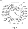
- FIG. 8 is a distal view of an exemplary first adhesive layer
- FIG. 9 is a proximal view of the first adhesive layer of FIG. 8 .
- FIG. 10 is a distal view of a part of the base plate including monitor interface
- FIG. 11 is a graphical presentation of parameter data
- FIG. 12 is a flow diagram of an exemplary method
- FIG. 13 is a flow diagram of an exemplary method
- FIG. 14 is an exemplary graphical representation of parameter data as a function of time
- FIG. 15 is an exemplary graphical representation of parameter data as a function of time
- FIG. 16 is an exemplary graphical representation of parameter data as a function of time
- FIG. 17 is an exemplary graphical representation of parameter data as a function of time and a whitening zone diameter as a function of time
- FIGS. 18 A- 18 B are exemplary graphical representations of peel force as a function of a peeling distance travelled by a peeling action exercising the peel force on a first adhesive layer of a base plate.
- stoma and ostomy are used to denote a surgically created opening bypassing the intestines or urinary tract system of a person.
- the words are used interchangeably, and no differentiated meaning is intended. The same applies for any words or phrases derived from these, e.g. “stomal”, “ostomies” etc.
- solid and liquid wastes emanating from the stoma may be referred to as both stomal “output,” “waste(s),” and “fluids” interchangeably.
- a subject having undergone ostomy surgery may be referred to as “ostomist” or “ostomate”—moreover, also as “patient” or “user”.
- HCP health care professional
- proximal side or surface of a layer an element, a device or part of a device
- the referral is to the skin-facing side or surface, when a user wears the ostomy appliance.
- distal side or surface of a layer an element, a device or part of a device
- the referral is to the side or surface facing away from the skin, when a user wears the ostomy appliance.
- the proximal side or surface is the side or surface closest to the user, when the appliance is fitted on a user and the distal side is the opposite side or surface—the side or surface furthest away from the user in use.
- the axial direction is defined as the direction of the stoma, when a user wears the appliance.
- the axial direction is generally perpendicular to the skin or abdominal surface of the user.
- a radial direction is defined as perpendicular to the axial direction.
- the words “inner” and “outer” may be used. These qualifiers should generally be perceived with respect to the radial direction, such that a reference to an “outer” element means that the element is farther away from a centre portion of the ostomy appliance than an element referenced as “inner”.
- “innermost” should be interpreted as the portion of a component forming a centre of the component and/or being adjacent to the centre of the component.
- outermost should be interpreted as a portion of a component forming an outer edge or outer contour of a component and/or being adjacent to that outer edge or outer contour.
- the present disclosure relates to an ostomy system and devices thereof, such as an ostomy appliance, a base plate for an ostomy appliance, a monitor device, and optionally one or more accessory devices. Further, methods related to the ostomy system and devices thereof are disclosed.
- An accessory device (also referred to as an external device) may be a mobile phone or other handheld device.
- An accessory device may be a personal electronic device, e.g. a wearable, such as a watch or other wrist-worn electronic device.
- An accessory device may be a docking station.
- the docking station may be configured to electrically and/or mechanically couple the monitor device to the docking station.
- the docking station may be configured for charging the monitor device and/or configured for transferring data between the monitor device and the docking station.
- the ostomy system may comprise a server device.
- the server device may be operated and/or controlled by the ostomy appliance manufacturer and/or a service centre.
- An ostomy system comprising an ostomy appliance and a monitor device, the ostomy appliance comprising a base plate is disclosed, wherein the monitor device is a monitor device as described herein.
- the present disclosure provides an ostomy system and devices thereof, such as an ostomy appliance, a base plate for an ostomy appliance, a monitor device, and optionally one or more accessory devices which either alone or together facilitate reliable determination of the nature, severity and rapidness of erosion and/or swelling in the adhesive material provided for attaching the base plate to the skin surface of a user.
- the ostomy system and devices thereof enable providing information to the user about the operating state of the base plate, and in turn enable providing an indication to the user of the severity and thus the remaining time frame for replacing the ostomy appliance without experiencing severe leakage and/or skin damage.
- the ostomy appliance comprises a base plate and an ostomy pouch (also referred to as an ostomy bag).
- the ostomy appliance may be a colostomy appliance, an ileostomy appliance or a urostomy appliance.
- the ostomy appliance may be a two-part ostomy appliance, i.e. the base plate and the ostomy pouch may be releasably coupled e.g. with a mechanical and/or an adhesive coupling, e.g. to allow that a plurality of ostomy pouches can be utilized (exchanged) with one base plate. Further, a two-part ostomy appliance may facilitate correct application of the base plate to skin, e.g.
- the ostomy appliance may be a one-part ostomy appliance, i.e. the base plate and the ostomy pouch may be fixedly attached to each other.
- the base plate is configured for coupling to a user's stoma and/or skin surrounding the stoma, such as a peristomal skin area.
- a base plate for an ostomy appliance comprising a first adhesive layer with a proximal side configured for attachment of the base plate to the skin surface of a user, the first adhesive layer having a stomal opening with a center point; and a plurality of electrodes including a ground electrode, a first electrode, and a optionally a second electrode, the ground electrode comprising a ground connection part, the first electrode comprising a first connection part, and the second electrode comprising a second connection part, wherein the ground electrode forms a ground for the first electrode and/or the second electrode.
- the base plate comprises a first adhesive layer.
- the first adhesive layer adheres to the user's skin (peristomal area) and/or to additional seals, such as sealing paste, sealing tape and/or sealing ring.
- the first adhesive layer may be configured for attachment of the base plate to the skin surface of a user.
- the first adhesive layer has a stomal opening with a center point or is at least prepared for forming a stomal opening with a center point.
- a base plate with three electrodes having sensing parts with contact to the first adhesive layer allows for determining erosion/swelling properties or characteristics of the first adhesive layer and/or determining a degree of erosion and/or swelling of the first adhesive layer.
- an optimum or improved use of an ostomy appliance is provided.
- the present disclosure facilitates that a base plate is not changed too early (leading to increased cell-stripping from the skin and increased risk of skin damage and further leading to increased costs and/or material waste) nor too late (leading to adhesive failure, leakage and/or skin damage from the aggressive output). Accordingly, the user or a health care professional is able to monitor and plan the use of the ostomy appliance.
- determination of erosion/swelling and classification of operating states of the ostomy appliance is useful in helping to reduce the risk of a user experiencing leakage from an ostomy appliance. Further, determination of degrees of erosion/swelling and classification of operating states of the ostomy appliance is further useful in helping reduce the risk of skin damage to a user. In particular, determination of degrees of erosion and/or swelling according to the present disclosure may help provide a clear distinction or differentiation between adhesive failure, leakage of output, which is harmful to the skin, and a sweating ostomate.
- determination of operating state and classification of operating states of the ostomy appliance is useful in helping to reduce the risk of a user experiencing leakage from an ostomy appliance. Further, determination of operating state and classification of operating states of the ostomy appliance is further useful in helping reduce the risk of skin damage to a user. In particular, determination of operating state according to the present disclosure may help provide a clear distinction or differentiation between adhesive failure, leakage of output, which is harmful to the skin, and a sweating ostomate.
- the present disclosure provides a simple, efficient, and easy-to-use ostomy appliance system with a high degree of comfort for a user.
- the first adhesive layer may be made of a first composition.
- the first composition may comprise one or more polyisobutenes and/or styrene-isoprene-styrene.
- the first composition may comprise one or more hydrocolloids.
- the first composition may be a pressure sensitive adhesive composition suitable for medical purposes comprising a rubbery elastomeric base and one or more water soluble or water swellable hydrocolloids.
- the first composition may comprise one or more polybutenes, one or more styrene copolymers, one or more hydrocolloids, or any combination thereof.
- the combination of the adhesive properties of the polybutenes and the absorbing properties of the hydrocolloids renders the first composition suitable for use in ostomy appliances.
- the styrene copolymer may for example be a styrene-butadiene-styrene block copolymer or a styrene-isoprene-styrene block copolymer.
- styrene-isoprene-styrene (SIS) block type copolymers are employed.
- the amount of styrene block-copolymer may be from 5% to 20% of the total adhesive composition.
- the butene component is suitably a conjugated butadiene polymer selected from polybutadiene, polyisoprene.
- the polybutenes are preferably present in an amount of from 35-50% of the total adhesive composition.
- the polybutene is polyisobutylene (PIB).
- Suitable hydrocolloids for incorporation in the first composition are selected from naturally occurring hydrocolloids, semisynthetic hydrocolloids, and synthetic hydrocolloids.
- the first composition may comprise 20-60% hydrocolloids.
- a preferred hydrocolloid is carboxymethyl cellulose (CMC).
- the first composition may optionally contain other components, such as fillers, tackifiers, plasticizers, and other additives.
- the first adhesive layer may have a plurality of sensor point openings.
- a sensor point opening of the first adhesive layer is configured to overlap a (sensing) part of an electrode, e.g. to form a sensor point.
- the sensor point openings of the first adhesive layer may comprise primary sensor point openings.
- the primary sensor point openings may comprise one or more primary first sensor point openings and one or more primary second sensor point openings, the primary first sensor point openings configured to overlap (sensing) parts of an electrode and the primary second sensor point openings configured to overlap (sensing) parts of another electrode different from the electrode at least partly overlapped by the primary first sensor point openings.
- the sensor point openings of the first adhesive layer may comprise secondary sensor point openings.
- the secondary sensor point openings may comprise one or more secondary first sensor point openings and one or more secondary second sensor point openings, the secondary first sensor point openings configured to overlap (sensing) parts of an electrode and the secondary second sensor point openings configured to overlap (sensing) parts of another electrode different from the electrode at least partly overlapped by the secondary first sensor point openings.
- the sensor point openings of the first adhesive layer may comprise tertiary sensor point openings.
- the tertiary sensor point openings may comprise one or more tertiary first sensor point openings and one or more tertiary second sensor point openings, the tertiary first sensor point openings configured to overlap (sensing) parts of an electrode and the tertiary second sensor point openings configured to overlap (sensing) parts of another electrode different from the electrode at least partly overlapped by the tertiary first sensor point openings.
- the first adhesive layer may have a substantially uniform thickness.
- the first adhesive layer may have a thickness in the range from 0.1 mm to 1.5 mm, e.g. in the range from 0.2 mm to 1.2 mm, such as 0.8 mm or 1.0 mm.
- the first adhesive layer may have a primary thickness in a primary part of the first adhesive layer, e.g. in a primary region within a primary radial distance or in a primary radial distance range from the center point of the stomal opening.
- the primary thickness may be in the range from 0.2 mm to 1.5 mm. such as about 1.0 mm.
- the primary radial distance may be in the range from 20 mm to 50 mm, such as in the range from 25 mm to 35 mm, e.g. 30 mm.
- the first adhesive layer may have a secondary thickness in a secondary part of the first adhesive layer, e.g. in a secondary region outside a secondary radial distance or in a secondary radial distance range from the center point of the stomal opening.
- the secondary thickness may be in the range from 0.2 mm to 1.0 mm, such as about 0.5 mm.
- the secondary radial distance may be in the range from 20 mm to 50 mm, such as in the range from 25 mm to 35 mm, e.g. 30 mm.
- the base plate may comprise a second layer.
- the second layer may be an adhesive layer.
- the second layer may have a second radial extension that is larger than a first radial extension of the first adhesive layer at least in a first angular range of the base plate. Accordingly, a part of a proximal surface of the second layer may be configured for attachment to the skin surface of a user.
- the part of a proximal surface of the second layer configured for attachment to the skin surface of a user is also denoted the skin attachment surface of the second adhesive layer.
- the second layer may have a stomal opening with a center point.
- the second adhesive layer may be made of a second composition.
- the second composition may comprise one or more polyisobutenes and/or styrene-isoprene-styrene.
- the second composition may comprise one or more hydrocolloids.
- the second composition may be a pressure sensitive adhesive composition suitable for medical purposes comprising a rubbery elastomeric base and one or more water soluble or water swellable hydrocolloids.
- the second composition may comprise one or more polybutenes, one or more styrene copolymers, one or more hydrocolloids, or any combination thereof.
- the combination of the adhesive properties of the polybutenes and the absorbing properties of the hydrocolloids renders the second composition suitable for use in ostomy appliances.
- the styrene copolymer may for example be a styrene-butadiene-styrene block copolymer or a styrene-isoprene-styrene block copolymer.
- styrene-isoprene-styrene (SIS) block type copolymers are employed.
- the amount of styrene block-copolymer may be from 5% to 20% of the total adhesive composition.
- the butene component is suitably a conjugated butadiene polymer selected from polybutadiene, polyisoprene.
- the polybutenes are preferably present in an amount of from 35-50% of the total adhesive composition.
- the polybutene is polyisobutylene (PIB).
- Suitable hydrocolloids for incorporation in the second composition are selected from naturally occurring hydrocolloids, semisynthetic hydrocolloids, and synthetic hydrocolloids.
- the second composition may comprise 20-60% hydrocolloids.
- a preferred hydrocolloid is carboxymethyl cellulose (CMC).
- the second composition may optionally contain other components, such as fillers, tackifiers, plasticizers, and other additives.
- the second adhesive layer and the first adhesive layer may have different properties.
- the second adhesive layer (second composition) and the first adhesive layer (first composition) may have different ratios of polyisobutenes, styrene-isoprene-styrene, and/or hydrocolloids.
- the second adhesive layer may provide a stronger attachment to the skin compared to attachment to the skin provided by the first adhesive layer.
- the second adhesive layer may be thinner than the first adhesive layer.
- the second adhesive layer may be less water and/or sweat absorbing than the first adhesive layer.
- the second adhesive layer may be less moldable than the first adhesive layer.
- the second adhesive layer may provide a second barrier against leakage.
- the second layer may have a substantially uniform thickness.
- the second layer may have a thickness in the range from 0.1 mm to 1.5 mm, e.g. in the range from 0.2 mm to 1.0 mm, such as 0.5 mm, 0.6 mm, or 0.7 mm.
- the base plate comprises one or more electrodes, such as a plurality of electrodes, such as two, three, four, five, six, seven or more electrodes.
- the electrodes e.g. some or all the electrodes, may be arranged between the first adhesive layer and the second adhesive layer.
- the electrodes may be arranged in an electrode assembly, e.g. an electrode layer.
- An electrode comprises a connection part for connecting the electrodes to other components and/or interface terminals/terminal elements.
- An electrode may comprise one or more conductor parts and/or one or more sensing parts.
- the electrode assembly may be arranged between the first adhesive layer and the second adhesive layer.
- the base plate e.g. the electrode assembly, may comprise a first electrode, a second electrode and optionally a third electrode.
- the base plate may comprise a fourth electrode and/or a fifth electrode.
- the base plate optionally comprises a sixth electrode.
- the base plate may comprise a ground electrode.
- the ground electrode may comprise a first electrode part.
- the first electrode part of the ground electrode may form a ground or reference for the first electrode.
- the ground electrode may comprise a second electrode part.
- the second electrode part of the ground electrode may form a ground or reference for the second electrode.
- the ground electrode may comprise a third electrode part.
- the third electrode part of the ground electrode may form a ground or reference for the third electrode.
- the ground electrode may comprise a fourth electrode part.
- the fourth electrode part of the ground electrode may form a ground or reference for the fourth electrode and/or the fifth electrode.
- the ground electrode or electrode parts of the ground electrode may be configured as or form a (common) reference electrode for some or all of the other electrodes of the electrode assembly.
- the ground electrode may also be denoted reference electrode.
- the electrodes are electrically conductive and may comprise one or more of metallic (e.g. silver, copper, gold, titanium, aluminium, stainless steel), ceramic (e.g. ITO), polymeric (e.g. PEDOT, PANI, PPy), and carbonaceous (e.g. carbon black, carbon nanotube, carbon fibre, graphene, graphite) materials.
- metallic e.g. silver, copper, gold, titanium, aluminium, stainless steel
- ceramic e.g. ITO
- polymeric e.g. PEDOT, PANI, PPy
- carbonaceous e.g. carbon black, carbon nanotube, carbon fibre, graphene, graphite
- the ground electrode may comprise a first electrode part and a second electrode part, the first electrode part forming the ground for the first electrode and the second electrode part forming the ground for the second electrode.
- the first electrode part may form a closed loop.
- the electrodes are electrically conductive and may comprise one or more of metallic (e.g. silver, copper, gold, titanium, aluminium, stainless steel), ceramic (e.g. ITO), polymeric (e.g. PEDOT, PANI, PPy), and carbonaceous (e.g. carbon black, carbon nanotube, carbon fibre, graphene, graphite) materials.
- metallic e.g. silver, copper, gold, titanium, aluminium, stainless steel
- ceramic e.g. ITO
- polymeric e.g. PEDOT, PANI, PPy
- carbonaceous e.g. carbon black, carbon nanotube, carbon fibre, graphene, graphite
- Two electrodes of the electrode assembly may form a sensor.
- the first electrode and the ground electrode (e.g. first electrode part of the ground electrode) may form a first sensor or first electrode pair.
- the second electrode and the ground electrode (e.g. second electrode part of the ground electrode) may form a second sensor or second electrode pair.
- the third electrode and the ground electrode (e.g. third electrode part of the ground electrode) may form a third sensor or third electrode pair.
- the fourth electrode and the ground electrode e.g. fourth electrode part of the ground electrode
- the fifth electrode and the ground electrode (e.g. fifth electrode part of the ground electrode) may form a fifth sensor or fifth electrode pair.
- the fourth electrode and the fifth electrode may form a sixth sensor or sixth electrode pair.
- the electrode assembly comprises the fourth electrode pair, the fifth electrode pair, and/or the sixth electrode pair.
- An electrode may comprise a sensing part or a plurality of sensing parts, i.e. the part(s) of an electrode that are used for sensing.
- the first electrode may comprise a first sensing part.
- the first sensing part may contact the first adhesive layer and is optionally arranged at least partly annularly around the stomal opening.
- the first electrode may comprise a first conductor part insulated from the first adhesive layer, e.g. by a masking element arranged between the first conductor part and the first adhesive layer.
- the first sensing part may extend at least 270 degrees around the stomal opening, such as at least 300 degrees around the stomal opening.
- the first sensing part of the first electrode may be arranged at a first ground distance from the first electrode part of the ground electrode.
- the first ground distance may be less than 5 mm, such as less than 3 mm, e.g. about 1.0 mm.
- the second electrode may comprise a second sensing part.
- the second sensing part may contact the first adhesive layer.
- the second sensing part may be arranged at least partly annularly around the stomal opening.
- the second sensing part may extend at least 270 degrees around the stomal opening, such as at least 300 degrees around the stomal opening.
- the second sensing part of the second electrode may be arranged at a second ground distance from the second electrode part of the ground electrode.
- the second ground distance may be less than 5 mm, such as less than 3 mm, e.g. about 1.0 mm.
- the first sensing part may be arranged at a first radial distance from the center point and the second sensing part may be arranged at a second radial distance from the center point.
- the second radial distance may be larger than the first radial distance.
- the second electrode may comprise a second conductor part insulated from the first adhesive layer, e.g. by a masking element arranged between the second conductor part and the first adhesive layer.
- the first radial distance may vary as a function of an angular position with respect to a zero direction from the center point.
- the second radial distance may vary as a function of an angular position with respect to a zero direction from the center point.
- the zero direction may be defined as the vertical upward direction when the base plate is in its intended wearing position on an upstanding user.
- the first radial distance may be in the range from 5 mm to 40 mm, such as in the range from 10 mm to 25 mm, e.g. about 14 mm.
- the second radial distance may be in the range from 10 mm to 50 mm, such as in the range from 10 mm to 25 mm, e.g. about 18 mm.
- the base plate may comprise a third electrode comprising a third connection part.
- the ground electrode may form a ground for the third electrode.
- the ground electrode may comprise a third electrode part, the third electrode part forming the ground for the third electrode.
- the third electrode may comprise a third conductor part insulated from the first adhesive layer, e.g. by a masking element arranged between the third conductor part and the first adhesive layer.
- the third electrode may comprise a third sensing part, the third sensing part contacting the first adhesive layer.
- the third sensing part may be arranged at least partly annularly around the stomal opening.
- the third sensing part may be arranged at a third radial distance from the center point.
- the third radial distance may be larger than the first radial distance and/or larger than the second radial distance.
- the third radial distance may be in the range from 15 mm to 50 mm. such as in the range from 20 mm to 30 mm, e.g. about 26 mm.
- the third sensing part may extend at least 270 degrees around the stomal opening, such as at least 300 degrees around the stomal opening.
- the third sensing part of the third electrode may be arranged at a third ground distance from the third electrode part of the ground electrode.
- the third ground distance may be less than 5 mm, such as less than 3 mm, e.g. about 1.0 mm.
- a base plate with a ground electrode, a first electrode, a second electrode, and a third electrode allows for a failsafe base plate in case e.g. the first electrode is cut or otherwise destroyed during preparation of the base plate.
- the base plate may comprise a fourth electrode comprising a fourth connection part.
- the ground electrode may form a ground for the fourth electrode.
- the ground electrode may comprise a fourth electrode part, the fourth electrode part forming the ground for the fourth electrode.
- the fourth electrode may comprise one or a plurality of fourth sensing parts, such as at least five fourth sensing parts.
- the fourth sensing parts may be distributed around the stomal opening or a center point thereof.
- the fourth sensing parts may be arranged at respective fourth radial distances from the center point.
- the fourth radial distance(s) may be larger than the third radial distance.
- the fourth radial distance(s) may be in the range from 25 mm to 50 mm, such as about 30 mm
- the base plate may comprise a fifth electrode comprising a fifth connection part.
- the ground electrode may form a ground for the fifth electrode.
- the ground electrode may comprise a fifth electrode part, the fifth electrode part forming the ground for the fifth electrode.
- the fifth electrode may comprise one or a plurality of fifth sensing parts, such as at least five fifth sensing parts.
- the fifth sensing parts may be distributed around the stomal opening or a center point thereof.
- the fifth sensing parts may be arranged at respective fifth radial distances from the center point.
- the fifth radial distance may be larger than the third radial distance.
- the fifth radial distance may be equal to or larger than the fourth radial distance.
- the fifth radial distance(s) may be in the range from 25 mm to 50 mm, such as about 30 mm.
- the first electrode may form an open loop.
- the second electrode may form an open loop and/or the third electrode may form an open loop.
- the fourth electrode may form an open loop.
- the fifth electrode may form an open loop. Open loop electrode(s) enables electrode arrangement in few or a single electrode layer.
- the base plate may comprise a second adhesive layer, wherein the plurality of electrodes is arranged between the first adhesive layer and the second adhesive layer.
- the electrode assembly may comprise a support layer, also denoted a support film.
- One or more electrodes may be formed, e.g. printed, on the proximal side of the support layer.
- One or more electrodes may be formed, e.g. printed, on the distal side of the support layer.
- one or more electrodes may be arranged between the support layer and the first adhesive layer.
- the electrode assembly may have a stomal opening with a center point.
- the support layer may comprise polymeric (e.g. polyurethane, PTFE, PVDF) and/or ceramic (e.g. alumina, silica) materials.
- the support layer is made of thermoplastic polyurethane (TPU).
- the support layer material may be made of or comprise one or more of polyester, a thermoplastic elastomer (TPE), polyamide, polyimide, Ethylene-vinyl acetate (EVA), polyurea, and silicones.
- thermoplastic elastomers of the support layer are styrenic block copolymers (TPS, TPE-s), thermoplastic polyolefin elastomers (TPO, TPE-o), thermoplastic Vulcanizates (TPV, TPE-v), thermoplastic polyurethanes (TPU), thermoplastic copolyester (TPC, TPE-E), and thermoplastic polyamides (TPA, TPE-A).
- TPS styrenic block copolymers
- TPO thermoplastic polyolefin elastomers
- TPV thermoplastic Vulcanizates
- TPU thermoplastic polyurethanes
- TPC thermoplastic copolyester
- TPE-A thermoplastic polyamides
- the electrode assembly/base plate may comprise a masking element configured to insulate at least parts of the electrodes from the first adhesive layer of the base plate.
- the masking element may comprise one or more, such as a plurality of, sensor point openings.
- the sensor point openings may comprise primary sensor point openings and/or secondary sensor point openings.
- the sensor point openings may comprise tertiary sensor point opening(s).
- the sensor point openings may comprise quaternary sensor point opening(s).
- a sensor point opening of the masking element overlaps at least one electrode of the electrode assembly when seen in the axial direction, e.g. to form a sensor point.
- a primary sensor point opening may overlap a (sensing) part of the ground electrode and/or a (sensing) part of the fourth electrode.
- a secondary sensor point opening may overlap a (sensing) part of the fourth electrode and/or a (sensing) part of the fifth electrode.
- a tertiary sensor point opening may overlap a (sensing) part of the fifth electrode and/or a (sensing) part of the ground electrode.
- the masking element may comprise one or more, such as a plurality of, terminal openings.
- a terminal opening may overlap with one or more connection parts of electrodes.
- each terminal opening overlaps with a single connection part of an electrode.
- the masking element may comprise polymeric (e.g. polyurethane, PTFE, PVDF) and/or ceramic (e.g. alumina, silica) materials.
- the masking element is made of or comprises thermoplastic polyurethane (TPU).
- the masking element is made of or comprises polyester.
- the masking element material may be made of or comprise one or more of polyester, a thermoplastic elastomer (TPE), polyimide, polyimide, Ethylene-vinyl acetate (EVA), polyurea, and silicones.
- thermoplastic elastomers of the masking element are styrenic block copolymers (TPS, TPE-s), thermoplastic polyolefin elastomers (TPO, TPE-o), thermoplastic Vulcanizates (TPV, TPE-v), thermoplastic polyurethanes (TPU), thermoplastic copolyester (TPC, TPE-E), and thermoplastic polyamides (TPA, TPE-A).
- the base plate may comprise a first intermediate element.
- the first intermediate element may be arranged between the electrodes/electrode layer and the first adhesive layer and/or between the second layer and the first adhesive layer.
- the first intermediate layer may be made of an insulating material.
- the base plate may comprise a release liner.
- the release liner is a protective layer that protects adhesive layer(s) during transport and storage and is peeled off by the user prior to applying the base plate on the skin.
- the release liner may have a stomal opening with a center point.
- the base plate may comprise a top layer.
- the top layer is a protective layer protecting the adhesive layer(s) from external strains and stress when the user wears the ostomy appliance.
- the electrodes e.g. some or all the electrodes, may be arranged between the first adhesive layer and the top layer.
- the top layer may have a stomal opening with a center point.
- the top layer may have a thickness in the range from 0.01 mm to 1.0 mm, e.g. in the range from 0.02 mm to 0.2 mm, such as 0.04 mm.
- the top layer may have a stomal opening with a center point.
- the base plate comprises a monitor interface.
- the monitor interface may be configured for electrically and/or mechanically connecting the ostomy appliance (base plate) to the monitor device.
- the monitor interface may be configured for wirelessly connecting the ostomy appliance (base plate) to the monitor device.
- the monitor interface of the base plate is configured to electrically and/or mechanically couple the ostomy appliance and the monitor device.
- the monitor interface of the base plate may comprise, e.g. as part of a first connector of the monitor interface, a coupling part for forming a mechanical connection, such as a releasable coupling between the monitor device and the base plate.
- the coupling part may be configured to engage with a coupling part of the monitor device for releasably coupling the monitor device to the base plate.
- the monitor interface of the base plate may comprise, e.g. as part of a first connector of the monitor interface, a plurality of terminals, such as two, three, four, five, six, seven or more terminals, for forming electrical connections with respective terminals of the monitor device.
- the monitor interface may comprise a ground terminal element forming a ground terminal.
- the monitor interface may comprise a first terminal element forming a first terminal, a second terminal element forming a second terminal and optionally a third terminal element forming a third terminal.
- the monitor interface may comprise a fourth terminal element forming a fourth terminal and/or a fifth terminal element forming a fifth terminal.
- the monitor interface optionally comprises a sixth terminal element forming a sixth terminal.
- the terminal elements of the monitor interface may contact respective electrodes (connection parts) of the base plate/electrode assembly.
- the first intermediate element may be arranged between the terminal elements and the first adhesive layer.
- the first intermediate element may cover or overlap terminal element(s) of the base plate when seen in the axial direction.
- the first adhesive layer may be protected or experience more evenly distributed mechanical stress from the terminal elements of the base plate, in turn reducing the risk of terminal elements penetrating or otherwise damaging the first adhesive layer.
- the first intermediate element may protect or mechanically and/or electrically shield the first adhesive layer from the terminal elements of the base plate.
- a terminal element such as the ground terminal element, the first terminal element, the second terminal element, the third terminal element, the fourth terminal element, the fifth terminal element and/or the sixth terminal element, may comprise a distal end and a proximal end.
- a terminal element such as the ground terminal element, the first terminal element, the second terminal element, the third terminal element, the fourth terminal element, the fifth terminal element and/or the sixth terminal element, may comprise a distal part, a centre part, and/or a proximal part.
- the distal part may be between the distal end and the centre part.
- the proximal part may be between the proximal end and the centre part.
- the proximal end/proximal part of a terminal element may contact a connection part of an electrode.
- a terminal element, such as the ground terminal element, the first terminal element, the second terminal element, the third terminal element, the fourth terminal element, the fifth terminal element and/or the sixth terminal element may be gold plated copper.
- the base plate may comprise a coupling ring or other coupling member for coupling an ostomy pouch to the base plate (two-part ostomy appliance).
- the center point may be defined as a center of the coupling ring.
- the base plate has a stomal opening with a center point.
- the size and/or shape of the stomal opening is typically adjusted by the user or nurse before application of the ostomy appliance to accommodate the user's stoma.
- the user forms the stomal opening during preparation of the base plate for application.
- a monitor device for an ostomy system comprising an ostomy appliance with a base plate
- the monitor device comprising a processor configured to apply a processing scheme; memory; a first interface connected to the processor and the memory, the first interface configured for collecting ostomy data from the base plate coupled to the first interface, the ostomy data comprising one or more, such as all, of first ostomy data from a first electrode pair of the base plate, second ostomy data from a second electrode pair of the base plate, and optionally third ostomy data from a third electrode pair of the base plate; and a second interface connected to the processor.
- To apply a processing scheme comprises obtain first parameter data based on the first ostomy data; obtain second parameter data based on the second ostomy data; and optionally obtain third parameter data based on the third ostomy data.
- To apply a processing scheme comprises determine an operating state of the base plate of the ostomy appliance. To determine the operating state of the base plate may be based on one or more, such as all, of the first parameter data, the second parameter data, the third parameter data, and fourth parameter data. The operating state may be indicative of a degree of radial erosion and/or radial swelling of the base plate, such as of the first adhesive layer, and/or an acute leakage risk for the ostomy appliance.
- the monitor device may be configured to transmit a monitor signal comprising monitor data indicative of the determined operating state of the base plate via the second interface.
- the monitor device may be configured to, in accordance with a determination that the operating state is a first operating state, transmit a first monitor signal comprising monitor data indicative of the first operating state of the base plate via the second interface.
- the monitor device may be configured to, in accordance with a determination that the operating state is a second operating state, transmit a second monitor signal comprising monitor data indicative of the second operating state of the base plate via the second interface.
- An operating state in the present disclosure is indicative of the dynamic internal state of the ostomy appliance (e.g. of the base plate of the ostomy appliance currently being worn by the user) optionally related to adhesive performance of the ostomy appliance.
- Adhesive performance of the ostomy appliance may be related to an internal condition of the ostomy appliance (e.g. of the base plate of the ostomy appliance), such as an internal condition of an adhesive layer of the ostomy appliance.
- the adhesive performance, and thereby the operating state may be affected by several factors, such as humidity, temperature, misplacement of the ostomy appliance on the stoma, and/or malfunction of the ostomy appliance. The one or more factors alone or in combination impact the adhesive performance of the ostomy appliance.
- the operating state may be varying in time.
- the operating state may be indicative of a degree of erosion of the base plate.
- Adhesive performance may be indicative of wear property, e.g. wear time and/or wear comfort.
- the operating state may comprise at least one of: a wear time, a quality of adhesion, and a moisture pattern representation.
- Wear time may comprise average wear time, nominal wear time, minimal wear time, maximal wear time, median wear time, and/or any of other statistical metric derivable from wear time.
- Wear time may comprise remaining wear time and/or current wear time and/or elapsed wear time.
- a quality of adhesion may comprise a metric indicative of erosion of a layer of the base plate, such as of the first adhesive layer.
- a moisture pattern representation may comprise one or more metrics or parameters representative or indicative of a moisture pattern (e.g. a moisture pattern type), e.g. a moisture pattern of the first adhesive layer.
- An operating state may be configured to indicate whether the ostomy appliance is properly operational based on its adhesive performance (e.g. wear property, e.g. wear time and/or wear comfort). For example, the operating state may be indicative of the severity and/or imminence of a leakage (e.g. low, medium, high or acute).
- wear property e.g. wear time and/or wear comfort
- the operating state may be indicative of the severity and/or imminence of a leakage (e.g. low, medium, high or acute).
- the first operating state of the base plate corresponds to a situation wherein the first adhesive layer of the base plate has experienced a first degree of radial erosion and/or radial swelling, e.g. the first adhesive layer is eroded or swelled to the first radial distance of the first electrode pair but not to the second radial distance of the second electrode pair.
- the second operating state of the base plate corresponds to a situation wherein the first adhesive layer of the base plate has experienced a second degree of radial erosion and/or radial swelling, e.g. the first adhesive layer is eroded or swelled to the second radial distance of the second electrode pair but not to the third radial distance of the third electrode pair.
- To obtain first parameter data based on the first ostomy data may comprise determining one or more first parameters based on the first ostomy data.
- To obtain second parameter data based on the second ostomy data may comprise determining one or more second parameters based on the second ostomy data.
- To obtain third parameter data based on the third ostomy data may comprise determining one or more third parameters based on the third ostomy data.
- determination of an operating state may be based on one or more first parameters, such as first primary parameter and/or first secondary parameter of first parameter data.
- determination of an operating state may be based on one or more second parameters, such as second primary parameter and/or second secondary parameter of the second parameter data.
- determination of an operating state may be based on one or more third parameters, such as third primary parameter and/or third secondary parameter of the third parameter data. In one or more exemplary monitor devices, determination of an operating state may be based on one or more fourth parameters, such as fourth primary parameter and/or fourth secondary parameter of the fourth parameter data.
- the monitor device comprises a monitor device housing optionally made of a plastic material.
- the monitor device housing may be an elongate housing having a first end and a second end.
- the monitor device housing may have a length or maximum extension along a longitudinal axis in the range from 1 cm to 15 cm.
- the monitor device housing may have a width or maximum extension perpendicular to the longitudinal axis in the range from 0.5 cm to 3 cm.
- the monitor device housing may be curve-shaped.
- the monitor device comprises a first interface connected to the processor.
- the first interface may be configured as an appliance interface for electrically and/or mechanically connecting the monitor device to the ostomy appliance.
- the appliance interface is configured to electrically and/or mechanically couple the monitor device and the ostomy appliance.
- the first interface may be configured as an accessory device interface for electrically and//or mechanically connecting the monitor device to an accessory device, such as a docking station.
- the first interface may be configured for coupling to a docking station of the ostomy system, e.g. for charging the monitor device and/or for data transfer between the monitor device and the docking station.
- the first interface of the monitor device may comprise a plurality of terminals, such as two, three, four, five, six, seven or more terminals, for forming electrical connections with respective terminals and/or electrodes of the ostomy appliance.
- One or more terminals of the first interface may be configured for forming electrical connections with an accessory device, e.g. with respective terminals of a docking station.
- the first interface may comprise a ground terminal.
- the first interface may comprise a first terminal, a second terminal and optionally a third terminal.
- the first interface may comprise a fourth terminal and/or a fifth terminal.
- the first interface optionally comprises a sixth terminal.
- the first interface has M terminals, wherein M is an integer in the range from 4 to 8.
- the first interface of the monitor device may comprise a coupling part for forming a mechanical connection, such as a releasable coupling between the monitor device and the base plate.
- the coupling part and the terminals of the first interface form (at least part of) a first connector of the monitor device.
- the monitor device comprises a power unit for powering the monitor device.
- the power unit may comprise a battery.
- the power unit may comprise charging circuitry connected to the battery and terminals of the first interface for charging the battery via the first interface, e.g. the first connector.
- the first interface may comprise separate charging terminal(s) for charging the battery.
- the monitor device may comprise a sensor unit with one or more sensors.
- the sensor unit is connected to the processor for feeding sensor data to the processor.
- the sensor unit may comprise an accelerometer for sensing acceleration and provision of acceleration data to the processor.
- the sensor unit may comprise a temperature sensor for provision of temperature data to the processor.
- the monitor device comprises a second interface connected to the processor.
- the second interface may be configured as an accessory interface for connecting, e.g. wirelessly connecting, the monitor device to one or more accessory devices.
- the second interface may comprise an antenna and a wireless transceiver, e.g. configured for wireless communication at frequencies in the range from 2.4 to 2.5 GHz.
- the wireless transceiver may be a Bluetooth transceiver, i.e. the wireless transceiver may be configured for wireless communication according to Bluetooth protocol, e.g. Bluetooth Low Energy, Bluetooth 4.0, Bluetooth 5.
- the second interface optionally comprises a loudspeaker and/or a haptic feedback element for provision of an audio signal and/or haptic feedback to the user, respectively.
- the processor may be configured to transmit a monitor signal, such as third monitor signal and/or fourth monitor signal via the loudspeaker.
- the processor may be configured to transmit a monitor signal, such as one or more, e.g. all, of first monitor signal, second monitor signal, third monitor signal, fourth monitor signal and default monitor signal, as a wireless monitor signal via the antenna and the wireless transceiver.
- the monitor device forms an integrated part of the ostomy appliance, e.g. the monitor device may form an integrated part of a base plate of the ostomy appliance.
- the first parameter data, the second parameter data, and the third parameter data may be indicative of resistance between the first electrode pair, the second electrode pair, and the third electrode pair, respectively.
- the first parameter data, the second parameter data, and the third parameter data may be indicative of voltage between the first electrode pair, the second electrode pair, and the third electrode pair, respectively (and thus indicative of resistance).
- the first parameter data, the second parameter data, and the third parameter data may be indicative of current between the first electrode pair, the second electrode pair, and the third electrode pair, respectively (and thus indicative of resistance).
- the first parameter data, the second parameter data, and the third parameter data may be indicative of a rate of change in resistance between the first electrode pair, the second electrode pair, and the third electrode pair, respectively.
- the first parameter data, the second parameter data, and the third parameter data may be indicative of a rate of change in voltage between the first electrode pair, the second electrode pair, and the third electrode pair, respectively.
- the first parameter data, the second parameter data, and the third parameter data may be indicative of a rate of change in current between the first electrode pair, the second electrode pair, and the third electrode pair, respectively.
- To determine an operating state of the base plate of the ostomy appliance may comprise to determine an operating state from a set of operating states.
- to determine an operating state may comprise selecting an operating state from a set of predefined operating states.
- the set of predefined operating states may comprise a number of operating states, such as at least two operating states, at least three operating states, at least four operating states, at least five operating states.
- the number of operating states may be in the range from four to twenty.
- the number of operating states in the set of predefined operating states. is larger than ten, such as larger than 20 or even larger than 50.
- the processor is configured to determine an operating state of the base plate if a change criterion is fulfilled.
- the change criterion may be based on the first parameter data, the second parameter data and/or the third parameter data.
- the change criterion may be fulfilled if parameter data changes, e.g. if a change in parameter data is larger than a change threshold.
- operating state determination may be conditional or dependent on a change in the parameter data, in turn leading to an optimum use of power or battery resources in the monitor device, since operating state determination is only performed when there may be a change in the operating state as a consequence of the change in parameter data.
- to determine an operating state of the base plate is based on a first criteria set based on the first parameter data and/or the second parameter data, wherein the operating state is determined to be the first operating state if the first criteria set is satisfied.
- the first criteria set may comprise one or more first criteria based on one or more of first parameter data, second parameter data and third parameter data.
- the first criteria set may comprise a first primary criterion based on the first parameter data.
- the first criteria set may comprise a first secondary criterion based on the second parameter data.
- the first criteria set may comprise a first tertiary criterion based on the third parameter data.
- to determine an operating state of the base plate may be based on a first threshold set comprising one or a plurality of first threshold values.
- the first threshold set may comprise one or a plurality of threshold values, e.g. to be applied in the first criteria set.
- the first threshold set may comprise a first primary threshold value.
- the first threshold set may comprise a first secondary threshold value.
- the first threshold set may comprise a first tertiary threshold value.
- the first criteria set may be given by or at least may comprise ( P _1_1 ⁇ TH _1_1), ( P _2_1> TH _1_2), and ( P _3_1> TH _1_3), wherein P_1_1 is a first primary parameter based on the first parameter data, TH_1_1 is a first primary threshold value, P_2_1 is a second primary parameter based on the second parameter data, TH_1_2 is a first secondary threshold value, P_3_1 is a third primary parameter based on the third parameter data, and TH_1_3 is a first tertiary threshold value, and wherein the first operating state is indicative of low degree of radial erosion or radial swelling on the base plate.
- the first threshold values may be the same or different, e.g. depending on the electrode configuration of the base plate.
- the first tertiary criterion (P_3_1 ⁇ TH_1_3) may be omitted in the first criteria set.
- the first operating state e.g. indicative of low degree of radial erosion or swelling on the base plate may be indicative of a radial progression of moisture to the first electrode pair (but not to the second electrode pair and not to the third electrode pair) which corresponds to e.g. an un-alarming and/or normal radial progression of moisture.
- the first threshold values may correspond to first resistance threshold values.
- the first primary threshold value TH_1_1 may correspond to an upper resistance threshold value.
- An upper resistance threshold value may be set to a value which is less than 30 Mega-Ohms, such as 25 Mega-Ohms, such as 20.5 Mega-Ohms, such as 20.4 Mega-Ohms.
- the first secondary threshold value TH_1_2 may correspond to the upper resistance threshold value.
- the first tertiary threshold value TH_1_3 may correspond to the upper resistance threshold value.
- the first primary parameter P_1_1 may be indicative of the resistance between the first electrode pair (first electrode and first electrode part of the ground electrode) of the base plate.
- the first parameter data may comprise a first secondary parameter which may be derived from the first primary parameter, and/or a first tertiary parameter, which may be derived from the first primary parameter.
- a first secondary parameter P_1_2 may comprise or be a gradient derived from the first primary parameter/first parameter data.
- a first primary parameter P_1_1 may be indicative of a voltage between the first electrode pair (first electrode and first electrode part of the ground electrode) of the base plate.
- the first threshold values may correspond to first voltage threshold values.
- the first primary threshold value TH_1_1 may correspond to an upper voltage threshold value.
- An upper voltage threshold value may be set to a value less than 5 Volts, such as 3 Volts, such as 2.86 Volts.
- the first secondary threshold value TH_1_2 may correspond to the upper voltage threshold value.
- the first tertiary threshold value TH_1_3 may correspond to the upper voltage threshold value.
- the first criteria set may comprise e.g. ( P _4_1> TH _1_4) wherein P_4_1 is a fourth primary parameter based on the fourth parameter data and indicative of the resistance, voltage, or current between the fourth electrode pair and TH_1_4 is a first quaternary threshold value, and wherein the first operating state is indicative of absence of fluid on the proximal side of the first adhesive layer of the base plate of the ostomy appliance.
- the first quaternary threshold value TH_1_4 may correspond to an upper resistance threshold value.
- An upper resistance threshold value may be set to a value which is less than 30 Mega-Ohms, such as 25 Mega-Ohms, such as 20.5 Mega-Ohms, such as 20.4 Mega-Ohms.
- the following additional criterion may be determined ( P _1_1 ⁇ TH _low), wherein P_1_1 is a first primary parameter based on the first parameter data, TH_low is a threshold value corresponding to a lower resistance threshold value.
- a lower resistance threshold value may be set to a value less than 1 Mega-Ohms, such as 100 kilo-Ohms, such as 80 kilo-Ohms, such as 79 kilo-Ohms. This is indicative of a saturation of the first electrode pair by the moisture detected and there are no further changes expected by the first primary parameter. Moisture is likely to continue its progression.
- the following additional criterion may be determined ( P _2_1 ⁇ TH _low), wherein P_2_1 is a second primary parameter based on the second parameter data, TH_low is a threshold value corresponding to a lower resistance threshold value.
- a lower resistance threshold value may be set to a value less than 1 Mega-Ohms, such as 100 kilo-Ohms, such as 80 kilo-Ohms, such as 79 kilo-Ohms. This is indicative of a saturation of the second electrode pair by the moisture detected and there are no further changes expected by the second primary parameter. Moisture is likely to continue its progression.
- the following additional criterion may be determined: ( P _3_1> TH _low),
- P_3_1 is a third primary parameter based on the third parameter data
- TH_low is a threshold value corresponding to a lower resistance threshold value.
- a lower resistance threshold value may be set to a value less than 1 Mega-Ohms, such as 100 kilo-Ohms, such as 80 kilo-Ohms, such as 79 kilo-Ohms. This is indicative of a saturation of the third electrode pair by the moisture detected and there are no further changes expected by the second primary parameter. Moisture is likely to continue its progression.
- one or more criteria of a criteria set may be based on timing information or one or more delay parameters based on the parameter data.
- one or more delay parameters or time differences related to different parameter data are determined.
- one or more first criteria of the first criteria set may be based on timing information (e.g. one or more delay parameters of the parameter data and/or one or more times where a parameter crosses a threshold).
- the timing information may comprise a time difference D_1_2_1 between a time T1 where P_1_1 crosses a threshold, such as TH_1_1, and a time T2 where P_2_1 crosses a threshold, such as TH_1_2.
- the timing information may comprise a time difference D_2_3_1 between a time T2 where P_2_1 crosses a threshold, such as TH_1_2, and a time T3 where P_3_1 crosses a threshold, such as TH_1_3.
- one or more criteria sets may comprise any of: D _1_2_1 >Z D _2_3_1 >Z
- Z is a time difference constant characterizing the progression of moisture (e.g. 3 h, e.g. 2 h). Different time difference constants may be employed in different criteria sets/for different time delays.
- one or more criteria sets such as the second criteria set and/or the third criteria set may comprise any of: D _1_2_1 >Z
- Z is a time difference constant characterizing the progression of moisture (e.g. 3 h, e.g. 2 h).
- the second primary parameter may be indicative of the resistance between the second electrode pair (second electrode and second electrode part of the ground electrode) of the base plate.
- the second parameter data may comprise a second secondary parameter, and/or a second tertiary parameter, which may be derived from the second primary parameter.
- a second secondary parameter may be indicative of a voltage between the second electrode pair (second electrode and second electrode part of the ground electrode) of the base plate.
- the third primary parameter may be indicative of resistance between the third electrode pair (third electrode and third electrode part of the ground electrode) of the base plate.
- the third parameter data may comprise a third secondary parameter, and/or a third tertiary parameter, which may be derived from the third primary parameter.
- a third secondary parameter may be indicative of a voltage between the second electrode pair (second electrode and second electrode part of the ground electrode) of the base plate.
- to determine an operating state of the base plate is based on a second criteria set based on the second parameter data and/or the third parameter data, wherein the operating state is determined to be the second operating state if the second criteria set is satisfied.
- the second criteria set may be based on the first parameter data.
- the second criteria set may comprise one or more second criteria based on one or more of first parameter data, second parameter data and third parameter data.
- the second criteria set may comprise a second primary criterion based on the first parameter data.
- the second criteria set may comprise a second secondary criterion based on the second parameter data.
- the second criteria set may comprise a second tertiary criterion based on the third parameter data.
- to determine an operating state of the base plate is based on a second threshold set comprising one or a plurality of second threshold values.
- the second threshold set may comprise one or a plurality of threshold values, e.g. to be applied in the second criteria set.
- the second threshold set may comprise a second primary threshold value.
- the second threshold set may comprise a second secondary threshold value.
- the second threshold set may comprise a second tertiary threshold value.
- the second criteria set may be given by or at least may comprise ( P _1_1 ⁇ TH _2_1), ( P _2_1 ⁇ TH _2_2), and ( P _3_1> TH _2_3) wherein P_1_1 is a first primary parameter based on the first parameter data and indicative of the resistance between the first electrode pair, TH_2_1 is a second primary threshold value, P_2_1 is a second primary parameter based on the second parameter data and indicative of the resistance between the second electrode pair, TH_2_2 is a second secondary threshold value, P_3_1 is a third primary parameter based on the third parameter data and indicative of the resistance between the third electrode pair, TH_2_3 is a second tertiary threshold value, and wherein the second operating state is indicative of medium degree of radial erosion or radial swelling on the base plate.
- the second threshold values may be the same or different, e.g. depending on the electrode configuration of the base plate.
- the second primary criterion (P_1_1 ⁇ TH_2_1) and/or the second tertiary criterion (P_3_1>TH_2_3) may be omitted in the second criteria set.
- the second operating state indicative of medium degree of radial erosion on the base plate may be indicative of a radial progression of moisture to the first electrode pair and the second electrode pair (and not the third electrode pair).
- the second operating state indicative of medium degree of radial erosion on the base plate may be indicative of a radial progression of moisture to the first electrode pair and to the second electrode pair.
- the second threshold values may correspond to second resistance threshold values.
- the second primary threshold value TH_2_1 may correspond to an upper resistance threshold value.
- An upper resistance threshold value may be set to a value which is less than 30 Mega-Ohms, such as 25 Mega-Ohms, such as 20.5 Mega-Ohms, such as 20.4 Mega-Ohms.
- the second secondary threshold value TH_2_2 may correspond to the upper resistance threshold.
- the second tertiary threshold value TH_2_3 may correspond to the upper resistance threshold value.
- the second primary threshold value TH_2_1 may correspond to a medium resistance threshold value.
- a medium resistance threshold value may be set to a value less than 10 Mega-Ohms, such as 5 Mega-Ohms, such as 3 Mega-Ohms, such as 2 Mega-Ohms, such as 1 Mega-Ohms.
- the second threshold values may correspond to second voltage threshold values.
- the second primary threshold value TH_2_1 may correspond to an upper voltage threshold value.
- An upper voltage threshold value may be set to a value less than 5 Volts, such as 3 Volts, such as 2.86 Volts.
- the second secondary threshold value TH_2_2 may correspond to the upper voltage threshold value.
- the second tertiary threshold value TH_2_3 may correspond to the upper voltage threshold value.
- the second primary threshold value TH_2_1 may correspond to a medium voltage threshold value.
- a medium resistance threshold value may be set to a value less than 10 Mega-Ohms, such as 5 Mega-Ohms, such as 3 Mega-Ohms, such as 2 Mega-Ohms, such as 1 Mega-Ohms.
- the second criteria set may comprise any of: D _1_2_1 >Z
- Z is a time difference constant characterizing the progression of moisture (e.g. 3 h, e.g. 2 h).
- to determine an operating state of the base plate is based on a default criteria set based on the first parameter data, wherein the operating state is determined to be the default operating state if the default criteria set is satisfied, and in accordance with a determination that the operating state is the default operating state, transmit a default monitor signal comprising monitor data indicative of the default operating state of the ostomy appliance.
- the default criteria set may be given by or at least may comprise ( P _1_1> TH _ D _1), ( P _2_1> TH _ D _2), and ( P _3_1> TH _ D _3) wherein P_1_1 is a first primary parameter based on the first parameter data and indicative of the resistance between the first electrode pair, TH_D_1 is a default primary threshold value, P_2_1 is a second primary parameter based on the second parameter data and indicative of the resistance between the second electrode pair, TH_D_2 is a default secondary threshold value, P_3_1 is a third primary parameter based on the third parameter data and indicative of the resistance between the third electrode pair, TH_D_3 is a default tertiary threshold value, and wherein the default operating state is indicative of very low or no degree of radial erosion or radial swelling on the base plate.
- the default threshold values (TH_D_1, TH_D_2 and TH_D_3)
- the default threshold values may correspond to default resistance threshold values.
- the second primary threshold value TH_D_1 may correspond to an upper resistance threshold value.
- An upper resistance threshold value may be set to a value which is less than 30 Mega-Ohms, such as 25 Mega-Ohms, such as 20.5 Mega-Ohms, such as 20.4 Mega-Ohms.
- the default secondary threshold value TH_D_2 may correspond to the upper resistance threshold.
- the default tertiary threshold value TH_D_3 may correspond to the upper resistance threshold value.
- the default threshold values may correspond to default voltage threshold values.
- the default primary threshold value TH_D_1 may correspond to an upper voltage threshold value.
- An upper voltage threshold value may be set to a value less than 5 Volts, such as 3 Volts, such as 2.86 Volts.
- the default secondary threshold value TH_D_2 may correspond to the upper voltage threshold value.
- the default tertiary threshold value TH_D_3 may correspond to the upper voltage threshold value.
- to determine an operating state of the base plate is based on a third criteria set based on the third parameter data, wherein the operating state is determined to be the third operating state if the third criteria set is satisfied, and in accordance with a determination that the operating state is the third operating state, transmit a third monitor signal comprising monitor data indicative of the third operating state of the ostomy appliance.
- the third operating state of the base plate corresponds to a situation wherein the first adhesive layer of the base plate has experienced a third degree of radial erosion or radial swelling, e.g. the first adhesive layer is eroded or swelled to the third radial distance of the third electrode pair.
- the third criteria set may be given by or at least comprise ( P _1_1 ⁇ TH _3_1), ( P _2_1 ⁇ TH _3_2), and ( P _3_1 ⁇ TH _3_3) wherein P_1_1 is a first primary parameter based on the first parameter data and indicative of the resistance between the first electrode pair, TH_3_1 is a third primary threshold value, P_2_1 is a second primary parameter based on the second parameter data and indicative of the resistance between the second electrode pair, TH_3_2 is a third secondary threshold value, P_3_1 is a third primary parameter based on the third parameter data and indicative of the resistance between the third electrode pair, TH_3_3 is a third tertiary threshold value, and wherein the third operating state is indicative of high degree of radial erosion or radial swelling on the base plate.
- the third threshold values may be the same or different, e.g. depending on the electrode configuration of the base plate.
- the third primary criterion (P_1_1 ⁇ TH_3_1) and/or the third secondary criterion (P_2_1 ⁇ TH_3_2) may be omitted in the third criteria set.
- the third operating state indicative of high degree of radial erosion on the base plate may be indicative of high likelihood of leakage, e.g. on the proximal side of the base plate, e.g. within a time period e.g. within the next 20 minutes.
- the third operating state may indicate a radial progression of moisture to the first electrode pair, the second electrode pair, and the third electrode pair.
- the third threshold values may correspond to third resistance threshold values.
- the third primary threshold value TH_3_1 may correspond to an upper resistance threshold value.
- the third secondary threshold value TH_3_2 may correspond to an upper resistance threshold value.
- the third tertiary threshold value TH_3_3 may correspond to an upper resistance threshold value.
- An upper resistance threshold value may be set to a value which is less than 30 Mega-Ohms, such as 25 Mega-Ohms, such as 20.5 Mega-Ohms, such as 20.4 Mega-Ohms.
- the third primary threshold value TH_3_1 may correspond to a lower resistance threshold value.
- a lower resistance threshold value may be set to a value less than 1 Mega-Ohms, such as 100 kilo-Ohms, such as 80 kilo-Ohms, such as 79 kilo-Ohms.
- the third secondary threshold value TH_3_2 may correspond to a medium resistance threshold.
- a medium resistance threshold value may be set to a value less than 10 Mega-Ohms, such as 5 Mega-Ohms, such as 3 Mega-Ohms, such as 2 Mega-Ohms, such as 1 Mega-Ohms.
- the third tertiary threshold value TH_3_3 may correspond to the upper resistance threshold.
- An upper resistance threshold value may be set to a value which is less than 30 Mega-Ohms, such as 25 Mega-Ohms, such as 20.5 Mega-Ohms, such as 20.4 Mega-Ohms.
- the third threshold values may correspond to third voltage threshold values.
- the third primary threshold value TH_3_1 may correspond to an upper voltage threshold value.
- the third secondary threshold value TH_3_2 may correspond to an upper voltage threshold value.
- the second tertiary threshold value TH_2_3 may correspond to the upper voltage threshold value.
- the third primary threshold value TH_3_1 may correspond to a lower voltage threshold value.
- a lower voltage threshold value may be set to a value which is less than 1 Volt, such as 0.5 Volt, such as 0.25 Volts, such as 0.22 Volts.
- the third secondary threshold value TH_3_2 may correspond to a medium voltage threshold value.
- a medium voltage threshold value may be set to a value less than 2 Volts, such as 1.5 Volts.
- the second tertiary threshold value TH_2_3 may correspond to the upper voltage threshold value.
- the third criteria set may comprise any of: D _1_2_1 ⁇ Z D _2_3_1 ⁇ Z
- Z is a time difference constant characterizing the progression of moisture (e.g. 3 h, e.g. 2 h), a time difference D_1_2_1 between a time T1 where P_1_1 crosses TH_1_1 and a time T2 where P_2_1 crosses TH_1_2, and a time difference D_2_3_1 between a time T2 where P_2_1 crosses TH_1_2 and a time T3 where P_3_1 crosses TH_1_3
- the ostomy data comprises fourth ostomy data from a fourth electrode pair of the base plate.
- a processing scheme may comprise to obtain fourth parameter data based on the fourth ostomy data, and determine an operating state of the base plate of the ostomy appliance based on the fourth parameter data.
- the monitor device may be configured to, in accordance with a determination that the operating state is a fourth operating state, transmit a fourth monitor signal comprising monitor data indicative of the fourth operating state of the ostomy appliance.
- the fourth operating state of the base plate corresponds to a situation, wherein the fourth electrode pair detects fluid, such as output, between the proximal surface of first adhesive layer and the skin of the user at a fourth radial distance, and thus there is a high risk of leakage from the ostomy appliance in the fourth operating state.
- the fourth criteria set may be given by or at least may comprise ( P _4_1 ⁇ TH _4_4) wherein P_4_1 is a fourth primary parameter based on the fourth parameter data and indicative of the resistance between the fourth electrode pair and TH_4_4 is a fourth quaternary threshold value, and wherein the fourth operating state is indicative of high risk of leakage from the ostomy appliance.
- the fourth quaternary threshold value TH_4_4 may correspond to an upper resistance threshold value.
- a fifth operating state of the base plate corresponds to a situation, wherein the fourth electrode pair detects fluid, such as sweat, between the proximal surface of first adhesive layer and the skin of the user at a fourth radial distance, and thus there is a no leakage from the ostomy appliance in the fifth operating state.
- fluid such as sweat
- the fifth operating state may be determined in accordance with a determination that one or more fifth criterion of a fifth criteria set are satisfied.
- the fifth criteria set may be given by or at least may comprise: ( P _4_1 ⁇ TH _5_1) ( P _4_2 ⁇ TH _5_2) ( P _4_3 ⁇ TH _5_3) ( ⁇ P _4_1 ⁇ V ) ( ⁇ P _4_2 ⁇ V ) and ( ⁇ P _4_3 ⁇ V )
- P_4_1 is a fourth primary parameter based on the fourth parameter data and indicative of the resistance between the fourth electrode pair
- P_4_2 is a fourth secondary parameter indicative of the resistance between the fourth electrode and the fifth electrode
- P_4_3 is a fourth tertiary parameter based on the fourth parameter data and indicative of the resistance between the fifth electrode pair
- TH_5_1 is a fifth primary threshold value
- TH_5_2 is a fifth secondary threshold value
- TH_5_3 is a fifth tertiary threshold value
- ⁇ P_4_3 is gradient of P_4_3, and V is a gradient limit (e.g.
- the fifth primary threshold value TH_5_1 may correspond to an upper resistance threshold value.
- TH_5_2 may correspond to an upper resistance threshold value.
- TH_5_3 may correspond to an upper resistance threshold value.
- An upper resistance threshold value may be set to a value which is less than 30 Mega-Ohms, such as 25 Mega-Ohms, such as 20.5 Mega-Ohms, such as 20.4 Mega-Ohms.
- the fifth operating state may refer to presence of sweat detected by the fourth parameter data indicating moisture detected omnidirectionally from the stomal opening and uniformally.
- the sixth operating state of the base plate corresponds to a situation, wherein the fourth electrode pair detects fluid, such as output, between the proximal surface of first adhesive layer and the skin of the user at a fourth radial distance, and thus there is a sudden leakage from the ostomy appliance in the sixth operating state.
- a sixth operating state may be determined in accordance with a determination that one or more sixth criteria of a sixth criteria set are satisfied.
- the sixth criteria set may comprise a sixth primary criterion, wherein the sixth primary criterion may comprise: ( P _4_1 ⁇ TH _6_1) and ( ⁇ P _4_1> V )
- the sixth criteria set may comprise a sixth secondary criterion, wherein the sixth secondary criterion may comprise: ( P _4_2 ⁇ TH _6_2) and ( ⁇ P _4_2> V )
- the sixth criteria set may comprise a sixth tertiary criterion, wherein the sixth tertiary criterion may comprise: ( P _4_3 ⁇ TH _6_3) and ( ⁇ P _4_3> V )
- P_4_1 is a fourth primary parameter based on the fourth parameter data and indicative of the resistance between the fourth electrode pair
- P_4_2 is a fourth secondary parameter indicative of the resistance between the fourth electrode and the fifth electrode
- P_4_3 is a fourth tertiary parameter indicative of the resistance between the fifth electrode pair (fifth electrode and ground electrode)
- TH_6_1 is a sixth primary threshold value
- TH_6_2 is a sixth secondary threshold value
- TH_6_3 is a sixth tertiary threshold value
- ⁇ P_4_3 is gradient of P_4_3, and V is a gradient limit (e.g.
- the sixth primary threshold value TH_6_1 may correspond to an upper resistance threshold value.
- TH_6_2 may correspond to an upper resistance threshold value.
- TH_6_3 may correspond to an upper resistance threshold value.
- An upper resistance threshold value may be set to a value which is less than 30 Mega-Ohms, such as 25 Mega-Ohms, such as 20.5 Mega-Ohms, such as 20.4 Mega-Ohms.
- the sixth operating state may refer to presence of output detected by the fourth parameter data indicating a sudden leak, e.g. a developing leak.
- the time T is below X minutes from the placement of the base plate, where X is between 5 to 60 minutes, and when any of P_1_1, P_2_1, P_3_1 in average over T are below a default threshold value corresponding to an upper resistance threshold value, this indicates that any of the first electrode pair, the second electrode pair, and the third electrode pair is cut (e.g. cut by the user when preparing the base plate for placement around the stoma).
- any of the first criteria set, the second criteria set, the third criteria set, the fourth criteria set, the default criteria set, the fifth criteria set, the sixth criteria set may be used to define one or more further criteria sets, and thereby to determine one or more operating states.
- different criteria sets may be used to determine the same operating state.
- to apply a processing scheme comprises to obtain common parameter data based on a plurality of the first ostomy data, the second ostomy data, and the third ostomy data; and determine the operating state of the base plate of the ostomy appliance based on the common parameter data.
- the common parameter data may also be denoted or comprise timing information.
- one or more criteria of a criteria set e.g. one or more first criteria of the first criteria set and/or one or more second criteria of the second criteria set, may be based on timing information or one or more delay parameters based on the parameter data.
- one or more delay parameters or time differences related to different parameter data e.g. related to the first parameter data and the second parameter data, are determined.
- to determine an operating state comprises to compare the first parameter data and the second parameter data, and wherein the operating state is based on the comparison between the first parameter data and the second parameter data.
- the second criteria set may comprise a second criterion where the first parameter data and the second parameter data are compared.
- to determine an operating state comprises to compare different parameter data, such as to compare the first parameter data and the third parameter data and/or to compare the second parameter data and the third parameter data, and wherein the operating state is based on the comparison between the different parameter data.
- the monitor data may be indicative of a condition and/or an operating state of the ostomy appliance, e.g. a condition and/or operating state of the base plate disclosed herein.
- the condition of the ostomy appliance or of the base plate disclosed herein may refer to a level of a physical property of at least a part of the ostomy appliance, such as a level of moisture and/or temperature of at least a part of the base plate, such as a level of a physical property of at least a layer of the base plate, such as a level of moisture and/or temperature of at least a layer of the base plate, such as a level of a physical property of at least an adhesive layer of the base plate (e.g.
- the interface is configured to obtain the monitor data by obtaining the monitor data indicative of the condition comprising a moisture level of a first adhesive layer of the base plate and/or a moisture level of a proximal side of the first adhesive layer.
- the moisture level may be seen as representative of a conductive path in the first adhesive layer, such as across the first adhesive layer.
- the monitor data comprises e.g. data representative of the measurement of the electrical properties of the first adhesive layer.
- the condition may be seen as a condition of the first adhesive layer.
- a method of monitoring an ostomy appliance comprising a base plate e.g. with a monitor device as disclosed herein, the method comprising: at a monitor device comprising a processor configured to apply a processing scheme; memory; a first interface connected to the processor and the memory; and a second interface connected to the processor: collecting ostomy data from the base plate and applying a processing scheme.
- Applying the processing scheme comprises: optionally obtaining first parameter data based on first ostomy data of the ostomy data; obtaining second parameter data based on second ostomy data of the ostomy data; obtaining third parameter data based on third ostomy data; and determining an operating state of the base plate based on one or more of the first parameter data, the second parameter data and the third parameter data, wherein the operating state may be indicative of a degree of radial erosion or radial swelling of the base plate and/or acute leakage risk for the ostomy appliance.
- the method comprises, in accordance with a determination that the operating state is a first operating state, transmitting a first monitor signal comprising monitor data indicative of the first operating state of the base plate via the second interface; and in accordance with a determination that the operating state is a second operating state, transmitting a second monitor signal comprising monitor data indicative of the second operating state of the base plate via the second interface.
- the ostomy system may comprise a docking station forming an accessory device of the ostomy system.
- the docking station may be configured to electrically and/or mechanically couple the monitor device to the docking station.
- the docking station may comprise a docking monitor interface.
- the docking monitor interface may be configured for electrically and/or mechanically connecting the monitor device to the docking station.
- the docking monitor interface may be configured for wirelessly connecting the monitor device to the docking station.
- the docking monitor interface of the docking station may be configured to electrically and/or mechanically couple the docking station and the monitor device.
- the docking monitor interface of the docking station may comprise, e.g. as part of a first connector of the docking monitor interface, a coupling part for forming a mechanical connection, such as a releasable coupling between the monitor device and the docking station.
- the coupling part may be configured to engage with a coupling part of the monitor device for releasably coupling the monitor device to the docking station.
- the docking monitor interface of the docking station may comprise, e.g. as part of a first connector of the docking monitor interface, a plurality of terminals, such as two, three, four, five, six, seven or more terminals, for forming electrical connections with respective terminals of the monitor device.
- the docking monitor interface may comprise a ground terminal.
- the docking monitor interface may comprise a first terminal and/or a second terminal.
- the docking station may comprise a third terminal.
- the docking monitor interface may comprise a fourth terminal and/or a fifth terminal.
- the docking monitor interface optionally comprises a sixth terminal.
- FIG. 1 illustrates an exemplary ostomy system.
- the ostomy system 1 comprises an ostomy appliance 2 including a base plate 4 and an ostomy pouch (not shown). Further, the ostomy system 1 comprises a monitor device 6 and an accessory device 8 (mobile telephone).
- the monitor device 6 is connectable to the base plate 4 via respective first connectors of the monitor device 6 and base plate 4 .
- the monitor device 6 is configured for wireless communication with the accessory device 8 .
- the accessory device 8 is configured to communicate with a server device 10 of the ostomy system 1 , e.g. via network 12 .
- the server device 10 may be operated and/or controlled by the ostomy appliance manufacturer and/or a service centre.
- Ostomy data or parameter data based on the ostomy data are obtained from electrodes/sensors of the ostomy appliance 2 with the monitor device 6 .
- the monitor device 6 processes the ostomy data and/or parameter data based on the ostomy data to determine monitor data that are transmitted to the accessory device 8 .
- the accessory device 8 is a mobile phone or smartphone, however the accessory device 8 may be embodied as another handheld device, such as a tablet device, or a wearable, such as a watch or other wrist-worn electronic device. Accordingly, the monitor device 6 is configured to determine and transmit monitor data to the accessory device 8 .
- the base plate 4 comprises a coupling member 14 in the form of a coupling ring 16 for coupling an ostomy pouch (not shown) to the base plate (two-part ostomy appliance).
- the base plate 4 has a stomal opening 18 with a center point 19 .
- the size and/or shape of the stomal opening 18 is typically adjusted by the user or nurse before application of the ostomy appliance to accommodate the user's stoma.
- the ostomy system 1 optionally comprises a docking station 20 forming an accessory device of the ostomy system 1 .
- the docking station comprises 20 comprises a docking monitor interface including a first connector 22 configured for electrically and/or mechanically connecting the monitor device 6 to the docking station 20 .
- the docking monitor interface may be configured for wirelessly connecting the monitor device to the docking station.
- the docking station 20 comprises a user interface 24 for receiving user input and/or providing feedback to the user on the operational state of the docking station 20 .
- the user interface 24 may comprise a touch-screen.
- the user interface 24 may comprise one or more physical buttons and/or one or more visual indicators, such as light emitting diodes.
- FIG. 2 is a schematic block diagram of an exemplary monitor device.
- the monitor device 6 comprises a monitor device housing 100 , a processor 101 , and one or more interfaces, the one or more interfaces including a first interface 102 (appliance interface) and a second interface 104 (accessory interface).
- the monitor device 6 comprises a memory 106 for storing ostomy data and/or parameter data based on the ostomy data.
- the memory 106 is connected to the processor 101 and/or the first interface 102 .
- the first interface 102 is configured as an appliance interface for electrically and/or mechanically connecting the monitor device 6 to the ostomy appliance, e.g. ostomy appliance 2 .
- the first interface 102 comprises a plurality of terminals for forming electrical connections with respective terminals of the ostomy appliance 2 (base plate 4 ).
- the first interface 102 comprises a ground terminal 108 , a first terminal 110 , a second terminal 112 and a third terminal 114 .
- the first interface 102 optionally comprises a fourth terminal 116 and a fifth terminal 118 .
- the first interface 102 of the monitor device 6 comprises a coupling part 120 for forming a mechanical connection, such as a releasable coupling between the monitor device and the base plate.
- the coupling part 120 and the terminals 108 , 110 , 112 , 114 , 116 , and 118 of the first interface 102 form (at least part of) a first connector of the monitor device 6 .
- the monitor device 6 comprises a power unit 121 for powering the monitor device and active components thereof, i.e. the power unit 121 is connected to the processor 101 , the first interface 102 , the second interface 104 , and memory 106 .
- the power unit comprises a battery and charging circuitry.
- the charging circuitry is connected to the battery and terminals of the first interface 102 for charging the battery via terminals of the first interface, e.g. terminals of the first connector.
- the second interface 104 of monitor device is configured as an accessory interface for connecting the monitor device 6 to one or more accessory devices such as accessory device 8 .
- the second interface 104 comprises an antenna 122 and a wireless transceiver 124 configured for wireless communication with accessory device(s).
- the second interface 104 comprises a loudspeaker 126 and/or a haptic feedback element 128 for provision of respective audio signal and/or haptic feedback to the user.
- the monitor device 6 optionally comprises a sensor unit 140 connected to the processor 101 .
- the sensor unit 140 comprises a temperature sensor for feeding temperature data to the processor and/or a G-sensor or accelerometer for feeding acceleration data to the processor 101 .
- the processor 101 is configured to apply a processing scheme
- the first interface 102 is configured for collecting ostomy data from the base plate coupled to the first interface, the ostomy data comprising first ostomy data from a first electrode pair of the base plate, second ostomy data from a second electrode pair of the base plate, and third ostomy data from a third electrode pair of the base plate.
- the ostomy data may be stored in the memory 106 and/or processed in the processor 101 in order to obtain parameter data.
- the processor 101 is configured to apply a processing scheme, wherein to apply a processing scheme comprises obtain first parameter data based on the first ostomy data; obtain second parameter data based on the second ostomy data; obtain third parameter data based on the third ostomy data.
- the processor 101 is configured to obtain first, second and third parameter data based on respective first, second and third ostomy data.
- To apply a processing scheme comprises to determine an operating state of the base plate of the ostomy appliance based on one or more, e.g. all, of the first parameter data, the second parameter data and the third parameter data, wherein the operating state is indicative of a degree of radial erosion or radial swelling of the base plate and/or acute leakage risk for the ostomy appliance.
- the monitor device 6 is configured to, in accordance with a determination that the operating state is a first operating state, transmit a first monitor signal comprising monitor data indicative of the first operating state of the base plate via the second interface; and in accordance with a determination that the operating state is a second operating state, transmit a second monitor signal comprising monitor data indicative of the second operating state of the base plate via the second interface.
- the monitor device 100 is configured to obtain ostomy data from the base plate coupled to the first interface 102 .
- the ostomy data may be stored in the memory 106 and/or processed in the processor 101 in order to obtain parameter data based on the ostomy data.
- FIG. 3 illustrates an exploded view of an exemplary base plate of an ostomy appliance.
- the base plate 4 comprises a first adhesive layer 200 with a stomal opening 18 A.
- a proximal surface of the first adhesive layer 200 adheres to the user's skin in the peristomal area and/or to additional seals, such as sealing paste, sealing tape and/or sealing ring.
- the base plate 4 optionally comprises a second adhesive layer 202 with a stomal opening 18 B.
- the base plate 4 comprises a plurality of electrodes arranged in an electrode assembly 204 .
- the electrode assembly 204 is arranged between the first adhesive layer 200 and the second adhesive layer 202 .
- the electrode assembly 204 comprises a support layer with stomal opening 18 C and electrodes formed on a proximal surface of the support layer.
- the base plate 4 comprises a release liner 206 that is peeled off by the user prior to applying the base plate 4 on the skin.
- the base plate 4 comprises a top layer 208 with a stomal opening 18 D and a coupling ring 209 for coupling an ostomy pouch to the base plate 4 .
- the top layer 208 is a protective layer protecting the second adhesive layer 202 from external strains and stress during use.
- the base plate 4 comprises a monitor interface.
- the monitor interface is configured for electrically and/or mechanically connecting the ostomy appliance (base plate 4 ) to the monitor device.
- the monitor interface of the base plate comprises a coupling part 210 for forming a mechanical connection, such as a releasable coupling between the monitor device and the base plate.
- the coupling part 210 is configured to engage with a coupling part of the monitor device for releasably coupling the monitor device to the base plate 4 .
- the monitor interface of the base plate 4 comprises a plurality of terminal elements respectively forming a plurality of terminals 212 for forming electrical connections with respective terminals of the monitor device.
- the coupling part 210 and the terminals 212 form a first connector 211 of the base plate 4 .
- the base plate 4 comprises a first intermediate element 213 on the distal side of the electrode assembly.
- the first intermediate element 213 is arranged between the terminal elements forming terminals 212 and the first adhesive layer (not shown).
- the first intermediate element 213 covers the terminal elements forming terminals 212 of the base plate 4 when seen in the axial direction and protects the first adhesive layer from mechanical stress from the terminal elements of the base plate.
- FIG. 4 illustrates an exploded view of an exemplary electrode assembly 204 of a base plate.
- the electrode assembly 204 has a distal side 204 A and a proximal side 204 B.
- the electrode assembly 204 comprises a support layer 214 with proximal surface 214 B and electrodes 216 arranged on the proximal side of the support layer 214 and including a ground electrode, a first electrode, a second electrode, a third electrode, a fourth electrode, and a fifth electrode, wherein each electrode has a respective connection part 217 for connecting the electrodes 216 to respective terminal elements of the monitor interface.
- the electrodes 216 are positioned and/or formed on a proximal side 214 B of the support layer 214 .
- electrode assembly 204 comprises a masking element 218 with proximal surface 218 B and configured to insulate electrode parts of electrodes 216 from the first adhesive layer of the base plate.
- the masking element 218 covers or overlap with parts of the electrodes 216 when seen in the axial direction.
- FIG. 5 is a proximal view of proximal surfaces of base plate parts of the base plate without the first adhesive layer and the release liner.
- the base plate 4 comprises a first intermediate element 213 on the distal side of the electrode assembly, i.e. between the electrode assembly 204 and the first adhesive layer (not shown).
- the first intermediate element 213 covers the terminal elements of the base plate 4 when seen in the axial direction and protects the first adhesive layer from mechanical stress from the terminal elements of the base plate.
- FIG. 6 is a distal view of an exemplary electrode configuration 220 of electrodes 216 of the electrode assembly 204 .
- the electrode configuration 220 /electrode assembly 204 comprises a ground electrode 222 , a first electrode 224 , a second electrode 226 , a third electrode 228 , a fourth electrode 230 , and a fifth electrode 232 .
- the ground electrode 222 comprises a ground connection part 222 A and the first electrode 224 comprises a first connection part 224 A.
- the second electrode 226 comprises a second connection part 226 A and the third electrode 228 comprises a third connection part 228 A.
- the fourth electrode 230 comprises a fourth connection part 230 A and the fifth electrode 232 comprise a fifth connection part 232 A.
- the fourth electrode 230 comprises fourth sensing parts 230 B.
- the fifth electrode 232 comprises fifth sensing parts 232 B.
- the ground electrode 222 comprises a first electrode part 234 for forming a ground or reference for the first electrode 224 .
- the ground electrode 222 comprises a second electrode part 236 for forming a ground or reference for the second electrode 226 .
- the ground electrode 222 comprises a third electrode part 238 for forming a ground or reference for the third electrode 228 .
- the masking element 218 is arranged proximal to the electrodes 222 , 224 , 226 , 228 covering and insulating parts of the electrodes from the first adhesive and forming respective conductor parts of the electrodes 222 , 224 , 226 , 228 .
- the first sensing part 224 B extends circularly at least 330 degrees around the stomal opening at a first radial distance R 1 from the center point 19 .
- the first radial distance R 1 is 14 mm.
- the first electrode part 234 is arranged on the inside of the first sensing part (i.e. closer to the center point) and extends circularly at least 330 degrees around the stomal opening at a first ground distance RG 1 from the first sensing part (radially from the center point).
- the first ground distance RG 1 between sensing part of first electrode and first electrode part is about 1 mm.
- the second sensing part 226 B extends circularly at least 330 degrees around the stomal opening at a second radial distance R 2 from the center point 19 .
- the second radial distance R 2 is 18 mm.
- the second electrode part 236 is arranged on the inside of the second sensing part 226 B (i.e. closer to the center point) and extends circularly at least 330 degrees around the stomal opening at a second ground distance RG 2 from the second sensing part 226 B (radially from the center point).
- the second ground distance RG 2 between sensing part of second electrode and second electrode part is about 1 mm.
- the third sensing part 228 B extends circularly at least 330 degrees around the stomal opening at a third radial distance R 3 from the center point 19 .
- the third radial distance R 3 is about 26 mm.
- the third electrode part 238 is arranged on the inside of the third sensing part 228 B (i.e. closer to the center point) and extends circularly at least 330 degrees around the stomal opening at a third ground distance RG 3 from the third sensing part 228 B (radially from the center point).
- the third ground distance RG 3 between sensing part of third electrode and third electrode part is about 1 mm.
- the ground electrode 222 comprises a fourth electrode part 240 for forming a ground or reference for the fourth electrode 230 and the fifth electrode 232 .
- the fourth electrode part 240 of the ground electrode 222 extends at least 300 degrees around the stomal opening and comprises ground sensing parts 222 B.
- the fourth sensing parts 230 B, fifth sensing parts 232 B, and ground sensing parts of the fourth electrode part 240 are circularly distributed around the center point 19 at a leakage radius from the center point.
- the fourth sensing parts 230 B, fifth sensing parts 232 B, and ground sensing parts of the fourth electrode part may have a radial extension larger than 1.0 mm, such as in the range from 1.5 mm to 3.0 mm, e.g. about 2.0 mm.
- the fourth sensing parts 230 B, fifth sensing parts 232 B, and ground sensing parts of the fourth electrode part 240 may have a circumferential extension (perpendicular to the radial extension) larger than 1.0 mm, such as in the range from 2.5 mm to 5.0 mm, e.g. about 3.5 mm.
- FIG. 7 is a distal view of an exemplary masking element.
- the masking element 218 optionally has a plurality of terminal openings including six terminal openings.
- the plurality of terminal openings comprises a ground terminal opening 242 , a first terminal opening 244 , a second terminal opening 246 , a third terminal opening 248 , a fourth terminal opening 250 , and a fifth terminal opening 252 .
- the terminal openings 242 , 244 , 246 , 248 , 250 , 252 of the masking element 218 are configured to overlap and/or be aligned with respective connection parts 222 A, 224 A, 226 A, 228 A, 230 A, 232 A of the electrodes of the electrode assembly.
- the masking element 218 has a plurality of sensor point openings.
- the sensor point openings comprise primary sensor point openings shown within dotted line 254 , each primary sensor point opening configured to overlap a part of the ground electrode 222 and/or a part of the fourth electrode 230 .
- the primary sensor point openings 254 comprise, in the illustrated exemplary masking element, five primary first sensor point openings 254 A each configured to overlap a part of the ground electrode 222 .
- the primary sensor point openings 254 comprise, in the illustrated exemplary masking element, four primary second sensor point openings 254 B each configured to overlap a part of the fourth electrode 230 .
- the sensor point openings comprise secondary sensor point openings shown within dotted line 256 , each second sensor point opening configured to overlap a part of the fourth electrode 230 and/or a part of the fifth electrode 232 .
- the secondary sensor point openings 256 comprise, in the illustrated exemplary masking element, five secondary first sensor point openings 256 A each configured to overlap a part of the fifth electrode 232 .
- the secondary sensor point openings 256 comprise, in the illustrated exemplary masking element, four secondary second sensor point openings 256 B each configured to overlap a part of the fourth electrode 230 .
- the sensor point openings comprise tertiary sensor point openings shown within dotted line 258 , each tertiary sensor opening configured to overlap a part of the fifth electrode 232 and/or a part of the ground electrode 222 .
- the tertiary sensor point openings 258 comprise, in the illustrated exemplary masking element, five tertiary first sensor point openings 258 A each configured to overlap a part of the fifth electrode 232 .
- the tertiary sensor point openings 258 comprise, in the illustrated exemplary masking element, four tertiary second sensor point openings 258 B each configured to overlap a part of the ground electrode 222 .
- FIG. 8 is a distal view of an exemplary first adhesive layer.
- the first adhesive layer 200 has a plurality of sensor point openings.
- the sensor point openings of the first adhesive layer comprise primary sensor point openings shown within dotted line 260 , each primary sensor point opening configured to overlap a part of the ground electrode 222 and/or a part of the fourth electrode 230 of the electrode assembly.
- the primary sensor point openings comprise, in the illustrated exemplary first adhesive layer, five primary first sensor point openings 260 A each configured to overlap a part of the ground electrode 222 .
- the primary sensor point openings comprise, in the illustrated exemplary first adhesive layer, four primary second sensor point openings 260 B each configured to overlap a part of the fourth electrode 230 .
- the sensor point openings of the first adhesive layer comprise secondary sensor point openings shown within dotted line 262 , each second sensor point opening configured to overlap a part of the fourth electrode 230 and/or a part of the fifth electrode 232 of the electrode assembly.
- the secondary sensor point openings comprise, in the illustrated exemplary first adhesive layer, five secondary first sensor point openings 262 A each configured to overlap a part of the fifth electrode 232 .
- the secondary sensor point openings comprise, in the illustrated exemplary first adhesive layer, four secondary second sensor point openings 262 B each configured to overlap a part of the fourth electrode 230 .
- the sensor point openings of the first adhesive layer comprise tertiary sensor point openings shown within dotted line 264 , each tertiary sensor opening configured to overlap a part of the fifth electrode 232 and/or a part of the ground electrode 222 of the electrode assembly.
- the tertiary sensor point openings comprise, in the illustrated exemplary first adhesive layer, five tertiary first sensor point openings 264 A each configured to overlap a part of the fifth electrode 232 .
- the tertiary sensor point openings comprise, in the illustrated exemplary first adhesive layer, four tertiary second sensor point openings 264 B each configured to overlap a part of the ground electrode 222 .
- FIG. 9 is a proximal view of the first adhesive layer of FIG. 8 .
- FIG. 10 is a more detailed distal view of a part of the base plate 4 .
- Monitor interface of the base plate comprises the first connector 211 .
- the first connector 211 comprises coupling part 210 configured to releasably couple the monitor device to the base plate and thus forming a releasable coupling.
- the first connector 211 /monitor interface comprises a plurality of terminals formed by respective terminal elements for forming respective electrical connections with respective terminals of the monitor device.
- the plurality of terminals of the first connector 211 /monitor interface comprises a ground terminal element 282 forming a ground terminal 282 A, a first terminal element 284 forming a first terminal 284 , a second terminal element 286 forming a second terminal 286 A, and optionally a third terminal element 288 forming a third terminal 288 A.
- the monitor interface optionally comprises a fourth terminal element 290 forming a fourth terminal 290 A and/or a fifth terminal element 292 forming a fifth terminal 290 .
- the terminal elements 282 , 284 , 286 , 288 , 290 , 292 contact respective connection parts 222 A, 224 A, 226 A, 228 A, 230 a , 232 A of electrodes 222 , 224 , 226 , 228 , 230 , 232 .
- the position of the first connector on the base plate, the number of terminals and the position of the terminals in the coupling part may be adapted to the electrode configuration used in the electrode assembly of the base plate.
- FIG. 11 is an exemplary graphical presentation of primary parameters being the resistance between respective electrode pairs of base plate 4 as a function of time during use of the base plate.
- the base plate is in a default state.
- the first primary parameter P_1_1 (resistance between first electrode and ground electrode (first electrode part)) drops below a first primary threshold value TH_1_1 to fulfil a first criterion set, and the monitor device determines that the base plate is now in a first operating state.
- the second primary parameter P_2_1 (resistance between second electrode and ground electrode (second electrode part)) drops below a second secondary threshold value TH_2_2 to fulfil a second criterion set, and the monitor device determines that the base plate is now in a second operating state.
- the third primary parameter P_3_1 (resistance between third electrode and ground electrode (third electrode part)) drops below a third tertiary threshold value TH_3_3 to fulfil a third criteria set, and the monitor device determines that the base plate is now in a third operating state.
- the fourth primary parameter P_4_1 (e.g.
- FIG. 12 is a flow diagram of a method of monitoring an ostomy appliance comprising a base plate.
- the method 1000 comprises, at a monitor device comprising a processor configured to apply a processing scheme; memory; a first interface connected to the processor and the memory; and a second interface connected to the processor: collecting 1002 ostomy data from the base plate and applying a processing scheme.
- Applying a processing scheme comprises obtaining 1004 first parameter data based on first ostomy data of the ostomy data; obtaining 1006 second parameter data based on second ostomy data of the ostomy data; obtaining 1008 third parameter data based on third ostomy data; optionally obtaining 1010 fourth parameter data based on fourth ostomy data; and determining 1011 an operating state of the base plate based on the first parameter data, the second parameter data and the third parameter data, wherein the operating state is indicative of a degree of radial erosion or radial swelling of the base plate and/or acute leakage risk for the ostomy appliance. Determining 1011 an operating state of the base plate may be based on the fourth parameter data.
- the method 1000 comprises, in accordance 1012 with a determination that the operating state is a first operating state, transmitting 1014 a first monitor signal comprising monitor data indicative of the first operating state of the base plate via the second interface; and in accordance 1016 with a determination that the operating state is a second operating state, transmitting 1018 a second monitor signal comprising monitor data indicative of the second operating state of the base plate via the second interface.
- FIG. 13 is a flow diagram of a method of monitoring an ostomy appliance comprising a base plate.
- the method 1000 A comprises, at a monitor device comprising a processor configured to apply a processing scheme; memory; a first interface connected to the processor and the memory; and a second interface connected to the processor: collecting 1002 ostomy data from the base plate and applying a processing scheme.
- Applying a processing scheme comprises obtaining 1004 first parameter data based on first ostomy data of the ostomy data; obtaining 1006 second parameter data based on second ostomy data of the ostomy data; obtaining 1008 third parameter data based on third ostomy data; and optionally obtaining 1010 fourth parameter data based on fourth ostomy data.
- the method 1000 A comprises determining 1020 if a change criterion is fulfilled and, in accordance with the change criterion being satisfied, determining 1011 an operating state of the base plate based on the first parameter data, the second parameter data and the third parameter data, wherein the operating state is indicative of a degree of radial erosion or radial swelling of the base plate and/or acute leakage risk for the ostomy appliance.
- Determining 1011 an operating state of the base plate may be based on the fourth parameter data.
- the method 1000 A comprises transmitting 1014 a first monitor signal comprising monitor data indicative of the first operating state of the base plate via the second interface; and in accordance 1016 with a determination that the operating state is a second operating state, transmitting 1018 a second monitor signal comprising monitor data indicative of the second operating state of the base plate via the second interface.
- the method 1000 A returns to collecting ostomy data 1002 .
- operating state determination 1011 may be conditional or dependent on a change in the parameter data, in turn leading to an optimum use of power or battery resources in the monitor device, since operating state determination is only performed when there may be a change in the operating state as a consequence of the change in parameter data.
- FIG. 14 shows an exemplary graphical representation of parameter data as a function of time.
- the parameter data in the y-axis is in Volts and time is in the x-axis.
- Curve 1100 shows, as a function of time, first parameter data indicative of voltage measured by the first electrode pair of the base plate.
- Curve 1102 shows, as a function of time, second parameter data indicative of voltage measured by the second electrode pair of the base plate.
- Curve 1104 shows, as a function of time, third parameter data indicative of voltage measured by the third electrode pair of the base plate.
- Curves 1108 , 1116 , 1118 show, as a function of time, fourth primary parameter indicative of voltage measured by the fourth electrode pair of the base plate, fourth secondary parameter indicative of voltage measured by the fourth electrode and the fifth electrode of the base plate, and fourth tertiary parameter indicative of voltage measured by the fifth electrode pair of the base plate respectively.
- Curves 1110 , 1112 , 1114 show, as a function of time, a gradient of fourth primary parameter indicative of voltage gradient measured by the fourth electrode pair of the base plate, a gradient of fourth secondary parameter indicative of voltage gradient measured by the fourth electrode and the fifth electrode of the base plate (sixth electrode pair), and a gradient of fourth tertiary parameter indicative of voltage gradient measured by the fifth electrode pair of the base plate respectively.
- FIG. 14 shows the upper voltage threshold value represented as curve 1050 , the medium voltage threshold value represented as curve 1052 , the lower voltage threshold value represented as curve 1054 , and curve 1056 is a gradient limit.
- Curves 1108 , 1116 , 1118 as well as curves 1110 , 1112 , 1114 show that no moisture is detected at the proximal side of the first adhesive layer by the fourth electrode pair.
- curve 1100 shows that moisture is detected by the first electrode pair as the first parameter data crosses the upper voltage threshold value while curve 1102 shows that moisture is not detected by the second electrode pair as the second parameter data has not crossed the upper voltage threshold value.
- curve 1102 shows that moisture is detected by the second electrode pair as the second parameter data crosses the upper voltage threshold value. At this stage, it is determined that the ostomy appliance is in a second operating state.
- curve 1104 shows that moisture is detected by the third electrode pair as the third parameter data crosses the upper voltage threshold value. At this stage, it is determined that the ostomy appliance is in a third operating state.
- FIG. 15 shows an exemplary graphical representation of parameter data as a function of time.
- the parameter data in the y-axis is in Volts and time is in the x-axis.
- Curve 1202 shows, as a function of time, first parameter data indicative of voltage measured by the first electrode pair of the base plate.
- Curve 1204 shows, as a function of time, second parameter data indicative of voltage measured by the second electrode pair of the base plate.
- Curve 1200 shows, as a function of time, third parameter data indicative of voltage measured by the third electrode pair of the base plate.
- Curves 1206 , 1208 , 1210 show, as a function of time, fourth primary parameter indicative of voltage measured by the fourth electrode pair of the base plate, fourth secondary parameter indicative of voltage measured by the fourth electrode and the fifth electrode of the base plate (sixth electrode pair), and fourth tertiary parameter indicative of voltage measured by the fifth electrode pair of the base plate respectively.
- Curves 1212 , 1214 , 1216 show, as a function of time, a gradient of fourth primary parameter indicative of voltage gradient measured by the fourth electrode pair of the base plate, a gradient of fourth secondary parameter indicative of voltage gradient measured by the fourth electrode and the fifth electrode of the base plate, and a gradient of fourth tertiary parameter indicative of voltage gradient measured by the fifth electrode pair of the base plate respectively.
- FIG. 15 shows the upper voltage threshold value represented as curve 1050 , the medium voltage threshold value represented as curve 1052 , the lower voltage threshold value represented as curve 1054 , and curve 1056 represents a gradient limit.
- Curves 1206 , 1208 , 1210 as well as curves 1212 , 1214 , 1216 show that moisture is detected at the proximal side of the first adhesive layer by the fourth electrode pair, the fourth and fifth electrode, and the fifth electrode pair at a time starting at 60 h until 90 h.
- the three electrode pairs are triggered as shown by the decreases shown by 1206 , 1208 , 1210 and as the curves 1212 , 1214 , 1216 show a gradient below 80%, this is indicative of the presence of sweat at the proximal side of the first adhesive layer.
- curve 1202 shows that moisture is detected by the first electrode pair as the first parameter data crosses the upper voltage threshold value while curve 1204 shows that moisture is not detected by the second electrode pair as the second parameter data has not crossed the upper voltage threshold value.
- curve 1204 shows that moisture is detected by the second electrode pair as the second parameter data crosses the upper voltage threshold value. At this stage, it is determined that the ostomy appliance is in a second operating state.
- FIG. 16 shows an exemplary graphical representation of parameter data as a function of time.
- the parameter data in the y-axis is in Volts and time is in the x-axis.
- Curve 1300 shows, as a function of time, first parameter data indicative of voltage measured by the first electrode pair of the base plate.
- Curve 1302 shows, as a function of time, second parameter data indicative of voltage measured by the second electrode pair of the base plate.
- Curve 1304 shows, as a function of time, third parameter data indicative of voltage measured by the third electrode pair of the base plate.
- Curves 1306 , 1308 , 1310 show, as a function of time, fourth primary parameter indicative of voltage measured by the fourth electrode pair of the base plate, fourth secondary parameter indicative of voltage measured by the fourth electrode and the fifth electrode of the base plate, and fourth tertiary parameter indicative of voltage measured by the fifth electrode pair of the base plate respectively.
- Curves 1312 , 1314 , 1316 show, as a function of time, a gradient of fourth primary parameter indicative of voltage gradient measured by the fourth electrode pair of the base plate, a gradient of fourth secondary parameter indicative of voltage gradient measured by the fourth electrode and the fifth electrode of the base plate, and a gradient of fourth tertiary parameter indicative of voltage gradient measured by the fifth electrode pair of the base plate respectively.
- FIG. 16 shows the upper voltage threshold value represented as curve 1050 , the medium voltage threshold value represented as curve 1052 , the lower voltage threshold value represented as curve 1054 , and curve 1056 is a gradient limit.
- Curves 1306 , 1308 , 1310 as well as curves 1312 , 1314 , 1316 show that moisture is detected at the proximal side of the first adhesive layer by the fourth electrode pair at a time starting at around 25 h.
- leakage electrodes i.e. the fourth electrode pair, the fourth and fifth electrode, and the fifth electrode pair
- As leakage electrodes are trigger as shown by the decreases shown by 1306 , 1308 , 1310 and as curve 1312 , 1314 , 1316 show a gradient above 80%, this is indicative of the presence of output at the proximal side of the first adhesive layer. This indicate severe leakage. It may be determined that the ostomy appliance is in a sixth operating state.
- curve 1300 shows that moisture is detected by the first electrode pair as the first parameter data crosses the upper voltage threshold value while curve 1302 shows that moisture is not detected by the second electrode pair as the second parameter data has not crossed the upper voltage threshold value.
- curve 1302 shows that moisture is detected by the second electrode pair as the second parameter data crosses the upper voltage threshold value. At this stage, it is determined that the ostomy appliance is in a second operating state.
- curve 1304 shows that moisture is detected by the third electrode pair as the third parameter data crosses the upper voltage threshold value.
- curve 1304 indicates that moisture has reached the third electrode pair, and the present disclosure enables determining that the ostomy appliance is in a third operating state.
- FIG. 17 shows an exemplary graphical representation of parameter data as a function of time and a whitening zone diameter (e.g. related to a radial thickness of a whitening ring surrounding the stomal opening) as a function of time.
- FIG. 17 illustrates the moisture propagation in the first adhesive layer as a function of time, and illustrates a correlation between parameter data detected by the first electrode pair and the second electrode pair of the base plate and actual moisture on the proximal surface of the first adhesive layer of the base plate.
- the actual moisture propagation in the first adhesive layer may appear as a whitening zone (e.g. a white ring around the stomal opening) in the first adhesive layer.
- FIG. 17 is obtained by experiments where water is applied from the stomal opening of the based plate to follow, using the electrodes of the base plate, the radial propagation of moisture leading to radial erosion of the first adhesive layer of the base plate.
- Curve 1502 shows, as a function of time, first parameter data indicative of voltage measured by the first electrode pair of the base plate.
- Curve 1504 shows, as a function of time, second parameter data indicative of voltage measured by the second electrode pair of the base plate.
- Curve 1506 shows a diameter of the white ring as a function of time.
- the first parameter data shows a decrease in e.g. voltage measured by the first electrode pair over time. It is also seen that the voltage of the second electrode pair drops at a later time than when the first parameter data shows a decrease in e.g. voltage dropped. This correlates well with the diameter of the white ring which goes from around 25-26 mm when the first electrode pair is triggered (e.g.
- first parameter data shows a decrease
- second parameter data shows a decrease
- an ostomy appliance with a base plate as disclosed herein is an optimal state (corresponding to a first operating state) when the radial thickness of the whitening ring is between 0-15 mm (for a user not in compliance with a preferred use), such as between 0-7 mm (for a user in compliance with a preferred use), such as between 0-5 mm (recommended by a nurse).
- an ostomy appliance with a base plate as disclosed herein is in suboptimal state (corresponding to a second operating state) and thereby indicate a consideration to change the base plate when the radial thickness of the whitening ring is such as between 5-10 mm (recommended by a nurse), between 7 mm and 10 mm (for a user in compliance with a preferred use), and/or between 15 mm and 30 mm (for a user not in compliance with a preferred use).
- an ostomy appliance with a base plate as disclosed herein is in a poor state (corresponding to a third operating state) and indicate a request to change the base plate when the radial thickness of the whitening ring is more than 10 mm (recommended by a nurse), such as more than 15 mm (for a user in compliance with a preferred use), such as more than 30 mm (for a user not in compliance with a preferred use).
- an ostomy appliance with a base plate as disclosed herein is an optimal state (corresponding to a first operating state) when the radial thickness of the whitening ring is between 0-20 mm (for a user not in compliance with a preferred use), such as between 0-10 mm (for a user in compliance with a preferred use), such as between 0-10 mm (recommended by a nurse).
- an ostomy appliance with a base plate as disclosed herein is in suboptimal state (corresponding to a second operating state) and thereby indicate a consideration to change the base plate when the radial thickness of the whitening ring is such as between 10 mm and 20 mm (recommended by a nurse), between 10 mm and 20 (for a user in compliance with a preferred use), and/or between 20 mm and 40 mm (for a user not in compliance with a preferred use).
- an ostomy appliance with a base plate as disclosed herein is in a poor state (corresponding to a third operating state) and indicate a request to change the base plate when the radial thickness of the whitening ring is more than 20 mm (recommended by a nurse), such as more than 20 mm (for a user in compliance with a preferred use), such as more than 40 mm (for a user not in compliance with a preferred use).
- the disclosed methods, ostomy appliances, monitor devices, and accessory devices allow to accommodate the regional preferences of user in their use of the ostomy appliance so as to adjust thresholds for the operating states to the regional preference or use.
- FIGS. 18 A- 18 B shows exemplary graphical representations of peel force as a function of a peeling distance travelled by a peeling action exercising the peel force (e.g. perpendicularly to the proximal (or distal) surface of the first adhesive layer) on a first adhesive layer of a base plate disclosed herein.
- the peel force relates to a required force to peel the first adhesive layer off the skin surface.
- the peeling distance is with respect to one end of the first adhesive layer where the peel force starts to be exercised.
- the peeling distance relates to the size or length of the first adhesive layer and thereby may relate to a size or length of a portion the first adhesive layer affected by moisture and of a portion of the first adhesive layer not affected by moisture.
- the peel forces illustrated in FIGS. 18 A- 18 B are representative of adhesive performance of the first adhesive layer of the base plate to the skin surface.
- Composition of the first adhesive layer of the base plate as disclosed herein in one or more embodiments is formulated to provide adhesion of the base plate to the skin surface of the user when the base plate is worn and to maintain a dry and healthy skin surface. Avoiding maceration of skin when occluding the skin with an adhesive is done by transporting sweat away from the skin and into the first adhesive layer by means of e.g. hydrocolloid types and adhesive (e.g. hydrocolloid adhesives) forming part of an absorbing element of the first adhesive layer.
- hydrocolloid types and adhesive e.g. hydrocolloid adhesives
- the absorbing element when the absorbing element is in contact with moisture, (e.g. water, sweat, urine or faeces), the absorbing element absorb the moisture. This reduces the adhesion of the first adhesive layer to the skin.
- moisture e.g. water, sweat, urine or faeces
- the first adhesive layer goes from a dry adhesive state with acceptable adhesive performance (e.g. acceptable adhesion and cohesion) in to a wet adhesive state (e.g. reduced or non adhesion and low cohesion gel).
- acceptable adhesive performance e.g. acceptable adhesion and cohesion
- wet adhesive state e.g. reduced or non adhesion and low cohesion gel
- Curve 1602 of FIGS. 18 A and 18 B shows a peel force applied to the first adhesive layer as a function of a peeling distance travelled by a peeling action exercising the peel force on the first adhesive layer in a dry adhesive state, (e.g. not affected by moisture).
- the peel force is expressed in Newtons while the peeling distance is expressed in mm.
- the length of the first adhesive layer in dry adhesive state is illustrated by X5, corresponding to length of the first adhesive layer 1608 in dry adhesive state.
- Curve 1602 shows that the peel force applied to the first adhesive layer in a dry adhesive state is equal to Y1 when the peeling distance is less than X1. At X1, the peeling force drops as the peeling distance increases towards X5 and the end of the first adhesive layer.
- Curve 1604 of FIG. 18 A shows a peel force applied to the first adhesive layer as a function of a peeling distance travelled by a peeling action exercising the peel force on the first adhesive layer in a wet adhesive state, (e.g. affected by moisture to the point of reaching a completely wet adhesive state, where the first adhesive layer has become a gel).
- Curve 1604 shows that when the peeling distance is less than X2, the peel force applied to the first adhesive layer in a wet adhesive state is equal to Y2 which has much lower value than Y1. This shows that the adhesive performance of the first adhesive layer is reduced when the first adhesive layer is in a wet adhesive state. At X2, the peeling force drops as the peeling distance increases until the end of the first adhesive layer. It is noted that X2 is larger than X1, because the first adhesive layer in a wet adhesive state extends in volume, and thus in length due to the gelling of the components of the first adhesive layer.
- the peel experiment illustrated in FIG. 18 A shows a loss of adhesive performance when the first adhesive is in a wet adhesive state.
- Curve 1606 of FIG. 18 B shows a peel force applied to the first adhesive layer as a function of a peeling distance travelled by a peeling action exercising the peel force on the first adhesive layer illustrated 1610 which comprises a first portion 1610 A in a dry adhesive state and a second portion 1610 B in a wet adhesive state, (e.g. affected by moisture to the point of reaching a completely wet adhesive state, where the first adhesive layer has become a gel).
- Curve 1606 shows that when the peeling distance is less than X3, the peel force applied to the first adhesive layer in a wet adhesive state is equal to Y3 which has lower value than Y1. This shows that the adhesive performance of the first adhesive layer is reduced when the first adhesive layer comprises a portion in a wet adhesive state. At X3, the peeling force drops as the peeling distance increases until the end of the first adhesive layer. It is noted that X3 corresponds to the length of the portion 1610 A in dry adhesive state.
- the peel experiment illustrated in FIG. 18 B shows a loss of adhesive performance when the first adhesive is partly in a wet adhesive state.
- FIGS. 18 A- 18 B demonstrate that the operating state determined based on monitor data is indicative of adhesive performance of the base plate.
- monitor devices Also disclosed are monitor devices, ostomy system, and methods according to any one of the following items.
- a monitor device for an ostomy system comprising an ostomy appliance with a base plate, the monitor device comprising:
- Monitor device comprises to obtain first parameter data based on first ostomy data of the ostomy data from a first electrode pair of the base plate, and wherein to determine the operating state of the base plate of the ostomy appliance based on the parameter data comprises to determine the operating state of the base plate of the ostomy appliance based on the first parameter data.
- Item 5 Monitor device according to any of items 1-4, wherein the operating state is indicative of a degree of radial erosion of the base plate and/or acute leakage risk for the ostomy appliance.
- Item 6 Monitor device according to any of items 1-5, wherein the operating state is indicative of a degree of radial swelling of the base plate/first adhesive layer and/or is indicative of adhesive performance of the base plate/first adhesive layer.
- Item 7 Monitor device according to any of items 1-6, wherein the monitor device is configured to, in accordance with a determination that the operating state is a first operating state, transmit a first monitor signal comprising monitor data indicative of the first operating state of the base plate via the second interface.
- Item 8 Monitor device according to any of items 1-7, wherein the monitor device is configured to, in accordance with a determination that the operating state is a second operating state, transmit a second monitor signal comprising monitor data indicative of the second operating state of the base plate via the second interface.
- Item 9 Monitor device according to any of items 1-8, wherein to determine an operating state of the base plate is based on a first criteria set, e.g. based on the first parameter data and the second parameter data, wherein the operating state is determined to be the first operating state if the first criteria set is satisfied.
- Item 10 Monitor device according to any of items 1-9, wherein to determine an operating state of the base plate is based on a first threshold set comprising one or more first threshold values.
- Item 11 Monitor device according to any of items 1-10, wherein to determine an operating state of the base plate is based on a second criteria set, e.g. based on the second parameter data and the third parameter data, wherein the operating state is determined to be the second operating state if the second criteria set is satisfied.
- Item 12 Monitor device according to any of items 1-11, wherein to determine an operating state of the base plate is based on a second threshold set comprising one or more second threshold values.
- Monitor device according to any of items 1-12, wherein to determine an operating state of the base plate is based on a default criteria set, e.g. based on the first parameter data, wherein the operating state is determined to be the default operating state if the default criteria set is satisfied, and in accordance with a determination that the operating state is the default operating state, transmit a default monitor signal comprising monitor data indicative of the default operating state of the ostomy appliance.
- Item 14 Monitor device according to any of items 1-13, wherein to determine an operating state of the base plate is based on a third criteria set, e.g. based on the third parameter data, wherein the operating state is determined to be the third operating state if the third criteria set is satisfied, and in accordance with a determination that the operating state is the third operating state, transmit a third monitor signal comprising monitor data indicative of the third operating state of the ostomy appliance.
- a third criteria set e.g. based on the third parameter data
- the operating state is determined to be the third operating state if the third criteria set is satisfied, and in accordance with a determination that the operating state is the third operating state, transmit a third monitor signal comprising monitor data indicative of the third operating state of the ostomy appliance.
- Item 15 Monitor device according to any of items 1-14, wherein the first parameter data, the second parameter data, and the third parameter data are indicative of resistance between the first electrode pair, the second electrode pair, and the third electrode pair, respectively.
- Item 16 Monitor device according to any of items 1-15, wherein the first parameter data, the second parameter data, and the third parameter data are indicative of a rate of change in resistance between the first electrode pair, the second electrode pair, and the third electrode pair, respectively.
- Item 17 Monitor device according to any of items 1-16, wherein the ostomy data comprises fourth ostomy data from a fourth electrode pair of the base plate, and wherein to apply a processing scheme comprises:
- Item 18 Monitor device according to any of items 1-17, wherein the monitor device is configured to, in accordance with a determination that the operating state is a fourth operating state, transmit a fourth monitor signal comprising monitor data indicative of the fourth operating state of the ostomy appliance.
- Monitor device according to any of items 1-18, wherein to apply a processing scheme comprises:
- Item 20 Monitor device according to any of items 1-19 as dependent on item 9, wherein the first criteria set comprises a first primary criterion based on the first parameter data, a first secondary criterion based on the second parameter data, and a first tertiary criterion based on the third parameter data.
- the first criteria set comprises a first primary criterion based on the first parameter data, a first secondary criterion based on the second parameter data, and a first tertiary criterion based on the third parameter data.
- Item 21 Monitor device according to item 20, wherein the first criteria set is given by ( P _1_1 ⁇ TH _1_1), ( P _2_1> TH _1_2), and ( P _3_1> TH _1_3), wherein P_1_1 is a first primary parameter based on the first parameter data and indicative of the resistance between the first electrode pair, TH_1_1 is a first primary threshold value, P_2_1 is a second primary parameter based on the second parameter data and indicative of the resistance between the second electrode pair, TH_1_2 is a first secondary threshold value, P_3_1 is a third primary parameter based on the third parameter data and indicative of resistance between the third electrode pair, and TH_1_3 is a first tertiary threshold value, and wherein the first operating state is indicative of low degree of radial erosion on the base plate.
- P_1_1 is a first primary parameter based on the first parameter data and indicative of the resistance between the first electrode pair
- Item 22 Monitor device according to any of items 1-21 as dependent on item 11, wherein the second criteria set comprises a second primary criterion based on the first parameter data, a second secondary criterion based on the second parameter data, and a second tertiary criterion based on the third parameter data.
- the second criteria set comprises a second primary criterion based on the first parameter data, a second secondary criterion based on the second parameter data, and a second tertiary criterion based on the third parameter data.
- Item 23 Monitor device according to item 22, wherein the second criteria set is given by ( P _1_1 ⁇ TH _2_1), ( P _2_1 ⁇ TH _2_2), and ( P _3_1> TH _2_3) wherein P_1_1 is a first primary parameter based on the first parameter data and indicative of the resistance between the first electrode pair, TH_2_1 is a second primary threshold value, P_2_1 is a second primary parameter based on the second parameter data and indicative of the resistance between the second electrode pair, TH_2_2 is a second secondary threshold value, P_3_1 is a third primary parameter based on the third parameter data and indicative of the resistance between the third electrode pair, TH_2_3 is a second tertiary threshold value, and wherein the second operating state is indicative of medium degree of radial erosion on the base plate.
- Item 24 Monitor device according to any of items 1-23, wherein to determine an operating state comprises to compare the first parameter data and the second parameter data, and wherein the operating state is based on the comparison between the first parameter data and the second parameter data.
- Item 25 Monitor device according to any of items 1-24, wherein the second interface comprises a loudspeaker connected to the processor, and wherein the processor is configured to transmit a monitor signal via the loudspeaker.
- Item 26 Monitor device according to any of items 1-25, wherein the second interface comprises an antenna and a wireless transceiver, and wherein the processor is configured to transmit a monitor signal as a wireless monitor signal via the antenna and the wireless transceiver.
- Item 27 An ostomy system comprising an ostomy appliance and a monitor device, the ostomy appliance comprising a base plate, wherein the monitor device is a monitor device according to any of items 1-26.
- Item 28 A method of monitoring an ostomy appliance comprising a base plate, the method comprising:
- Method according to item 28 wherein obtaining parameter data based on the ostomy data comprises obtaining first parameter data based on first ostomy data of the ostomy data.
- Item 30 Method according to any of items 28-29, wherein obtaining parameter data based on the ostomy data comprises obtaining second parameter data based on second ostomy data of the ostomy data.
- Item 31 Method according to any of items 28-30, wherein obtaining parameter data based on the ostomy data comprises obtaining third parameter data based on third ostomy data of the ostomy data.
- Item 32 Method according to any of items 28-31, wherein determining an operating state of the base plate of the ostomy appliance is based on one or more of the first parameter data, the second parameter data and the third parameter data.
- Item 33 Method according to any of items 28-32, wherein the method comprises, in accordance with a determination that the operating state is a first operating state, transmitting a first monitor signal comprising monitor data indicative of the first operating state of the base plate via the second interface.
- Item 34 Method according to any of items 28-33, wherein the method comprises, in accordance with a determination that the operating state is a second operating state, transmitting a second monitor signal comprising monitor data indicative of the second operating state of the base plate via the second interface.
- Item 35 Method according to any of items 28-34, wherein the operating state is indicative of a degree of radial erosion of the base plate and/or acute leakage risk for the ostomy appliance.
- Item 36 Method according to any of items 28-35, wherein the operating state is indicative of a degree of radial swelling of the base plate.
- first”, “second”, “third” and “fourth”, “primary”, “secondary”, “tertiary” etc. does not imply any particular order, but are included to identify individual elements.
- the use of the terms “first”, “second”, “third” and “fourth”, “primary”, “secondary”, “tertiary” etc. does not denote any order or importance, but rather the terms “first”, “second”, “third” and “fourth”, “primary”, “secondary”, “tertiary” etc. are used to distinguish one element from another.
- the words “first”, “second”, “third” and “fourth”, “primary”, “secondary”, “tertiary” etc. are used here and elsewhere for labelling purposes only and are not intended to denote any specific spatial or temporal ordering.
- the labelling of a first element does not imply the presence of a second element and vice versa.
Abstract
Description
(P_1_1<TH_1_1),
(P_2_1>TH_1_2), and
(P_3_1>TH_1_3),
wherein P_1_1 is a first primary parameter based on the first parameter data, TH_1_1 is a first primary threshold value, P_2_1 is a second primary parameter based on the second parameter data, TH_1_2 is a first secondary threshold value, P_3_1 is a third primary parameter based on the third parameter data, and TH_1_3 is a first tertiary threshold value, and wherein the first operating state is indicative of low degree of radial erosion or radial swelling on the base plate. The first threshold values (TH_1_1, TH_1_2 and TH_1_3) may be the same or different, e.g. depending on the electrode configuration of the base plate. The first tertiary criterion (P_3_1<TH_1_3) may be omitted in the first criteria set. The first operating state, e.g. indicative of low degree of radial erosion or swelling on the base plate may be indicative of a radial progression of moisture to the first electrode pair (but not to the second electrode pair and not to the third electrode pair) which corresponds to e.g. an un-alarming and/or normal radial progression of moisture.
(P_4_1>TH_1_4)
wherein P_4_1 is a fourth primary parameter based on the fourth parameter data and indicative of the resistance, voltage, or current between the fourth electrode pair and TH_1_4 is a first quaternary threshold value, and wherein the first operating state is indicative of absence of fluid on the proximal side of the first adhesive layer of the base plate of the ostomy appliance. In one or more exemplary embodiments, the first quaternary threshold value TH_1_4 may correspond to an upper resistance threshold value. An upper resistance threshold value may be set to a value which is less than 30 Mega-Ohms, such as 25 Mega-Ohms, such as 20.5 Mega-Ohms, such as 20.4 Mega-Ohms.
(P_1_1<TH_low),
wherein P_1_1 is a first primary parameter based on the first parameter data, TH_low is a threshold value corresponding to a lower resistance threshold value. In one or more exemplary embodiments, a lower resistance threshold value may be set to a value less than 1 Mega-Ohms, such as 100 kilo-Ohms, such as 80 kilo-Ohms, such as 79 kilo-Ohms. This is indicative of a saturation of the first electrode pair by the moisture detected and there are no further changes expected by the first primary parameter. Moisture is likely to continue its progression.
(P_2_1<TH_low),
wherein P_2_1 is a second primary parameter based on the second parameter data, TH_low is a threshold value corresponding to a lower resistance threshold value. In one or more exemplary embodiments, a lower resistance threshold value may be set to a value less than 1 Mega-Ohms, such as 100 kilo-Ohms, such as 80 kilo-Ohms, such as 79 kilo-Ohms. This is indicative of a saturation of the second electrode pair by the moisture detected and there are no further changes expected by the second primary parameter. Moisture is likely to continue its progression.
(P_3_1>TH_low),
D_1_2_1>Z
D_2_3_1>Z
D_1_2_1>Z
(P_1_1<TH_2_1),
(P_2_1<TH_2_2), and
(P_3_1>TH_2_3)
wherein P_1_1 is a first primary parameter based on the first parameter data and indicative of the resistance between the first electrode pair, TH_2_1 is a second primary threshold value, P_2_1 is a second primary parameter based on the second parameter data and indicative of the resistance between the second electrode pair, TH_2_2 is a second secondary threshold value, P_3_1 is a third primary parameter based on the third parameter data and indicative of the resistance between the third electrode pair, TH_2_3 is a second tertiary threshold value, and wherein the second operating state is indicative of medium degree of radial erosion or radial swelling on the base plate. The second threshold values (TH_2_1, TH_2_2 and TH_2_3) may be the same or different, e.g. depending on the electrode configuration of the base plate. The second primary criterion (P_1_1<TH_2_1) and/or the second tertiary criterion (P_3_1>TH_2_3) may be omitted in the second criteria set.
D_1_2_1>Z
(P_1_1>TH_D_1),
(P_2_1>TH_D_2), and
(P_3_1>TH_D_3)
wherein P_1_1 is a first primary parameter based on the first parameter data and indicative of the resistance between the first electrode pair, TH_D_1 is a default primary threshold value, P_2_1 is a second primary parameter based on the second parameter data and indicative of the resistance between the second electrode pair, TH_D_2 is a default secondary threshold value, P_3_1 is a third primary parameter based on the third parameter data and indicative of the resistance between the third electrode pair, TH_D_3 is a default tertiary threshold value, and wherein the default operating state is indicative of very low or no degree of radial erosion or radial swelling on the base plate. The default threshold values (TH_D_1, TH_D_2 and TH_D_3) may be the same or different, e.g. depending on the electrode configuration of the base plate.
(P_1_1<TH_3_1),
(P_2_1<TH_3_2), and
(P_3_1<TH_3_3)
wherein P_1_1 is a first primary parameter based on the first parameter data and indicative of the resistance between the first electrode pair, TH_3_1 is a third primary threshold value, P_2_1 is a second primary parameter based on the second parameter data and indicative of the resistance between the second electrode pair, TH_3_2 is a third secondary threshold value, P_3_1 is a third primary parameter based on the third parameter data and indicative of the resistance between the third electrode pair, TH_3_3 is a third tertiary threshold value, and wherein the third operating state is indicative of high degree of radial erosion or radial swelling on the base plate. The third threshold values (TH_3_1, TH_3_2 and TH_3_3) may be the same or different, e.g. depending on the electrode configuration of the base plate. The third primary criterion (P_1_1<TH_3_1) and/or the third secondary criterion (P_2_1<TH_3_2) may be omitted in the third criteria set.
D_1_2_1<Z
D_2_3_1<Z
(P_4_1<TH_4_4)
wherein P_4_1 is a fourth primary parameter based on the fourth parameter data and indicative of the resistance between the fourth electrode pair and TH_4_4 is a fourth quaternary threshold value, and wherein the fourth operating state is indicative of high risk of leakage from the ostomy appliance.
(P_4_1<TH_5_1)
(P_4_2<TH_5_2)
(P_4_3<TH_5_3)
(∇P_4_1<V)
(∇P_4_2<V) and
(∇P_4_3<V)
(P_4_1<TH_6_1) and
(∇P_4_1>V)
(P_4_2<TH_6_2) and
(∇P_4_2>V)
(P_4_3<TH_6_3) and
(∇P_4_3>V)
-
- a processor configured to apply a processing scheme;
- memory;
- a first interface connected to the processor and the memory, the first interface configured for collecting ostomy data from the base plate coupled to the first interface; and
- a second interface connected to the processor,
wherein to apply a processing scheme comprises: - obtain parameter data based on the ostomy data; and
- determine an operating state of the base plate of the ostomy appliance based on the parameter data,
wherein the monitor device is configured to transmit a monitor signal comprising monitor data indicative of the determined operating state of the base plate via the second interface.
-
- obtain fourth parameter data based on the fourth ostomy data, and
- determine an operating state of the base plate of the ostomy appliance based on the fourth parameter data.
-
- obtain common parameter data based on a plurality of the first ostomy data, the second ostomy data, and the third ostomy data; and
- determine the operating state of the base plate of the ostomy appliance based on the common parameter data.
(P_1_1<TH_1_1),
(P_2_1>TH_1_2), and
(P_3_1>TH_1_3),
wherein P_1_1 is a first primary parameter based on the first parameter data and indicative of the resistance between the first electrode pair, TH_1_1 is a first primary threshold value, P_2_1 is a second primary parameter based on the second parameter data and indicative of the resistance between the second electrode pair, TH_1_2 is a first secondary threshold value, P_3_1 is a third primary parameter based on the third parameter data and indicative of resistance between the third electrode pair, and TH_1_3 is a first tertiary threshold value, and wherein the first operating state is indicative of low degree of radial erosion on the base plate.
(P_1_1<TH_2_1),
(P_2_1<TH_2_2), and
(P_3_1>TH_2_3)
wherein P_1_1 is a first primary parameter based on the first parameter data and indicative of the resistance between the first electrode pair, TH_2_1 is a second primary threshold value, P_2_1 is a second primary parameter based on the second parameter data and indicative of the resistance between the second electrode pair, TH_2_2 is a second secondary threshold value, P_3_1 is a third primary parameter based on the third parameter data and indicative of the resistance between the third electrode pair, TH_2_3 is a second tertiary threshold value, and wherein the second operating state is indicative of medium degree of radial erosion on the base plate.
-
- at a monitor device comprising a processor configured to apply a processing scheme; memory; a first interface connected to the processor and the memory; and a second interface connected to the processor:
- collecting ostomy data from the base plate;
- applying a processing scheme comprising:
- obtaining parameter data based on the ostomy data; and
- determining an operating state of the base plate based on the parameter data,
wherein the method comprises transmitting a monitor signal comprising monitor data indicative of the determined operating state of the base plate via the second interface.
- 1 ostomy system
- 2 ostomy appliance
- 4 base plate
- 6 monitor device
- 8 accessory device
- 10 server device
- 12 network
- 14 coupling member
- 16 coupling ring
- 18, 18A, 18B, 18C, 18D stomal opening
- 19 center point
- 20 docking station
- 22 first connector
- 24 user interface
- 100 monitor device housing
- 101 processor
- 102 first interface
- 104 second interface
- 106 memory
- 108 ground terminal of monitor device
- 110 first terminal of monitor device
- 112 second terminal of monitor device
- 114 third terminal of monitor device
- 116 fourth terminal of monitor device
- 118 fifth terminal of monitor device
- 120 coupling part
- 121 power unit
- 122 antenna
- 124 wireless transceiver
- 126 loudspeaker
- 128 haptic feedback element
- 140 sensor unit
- 200 first adhesive layer
- 200A distal surface of first adhesive layer
- 200B proximal surface of first adhesive layer
- 202 second adhesive layer
- 202A distal surface of second adhesive layer
- 202B proximal surface of second adhesive layer
- 204 electrode assembly
- 204A distal surface of electrode assembly
- 204B proximal surface of electrode assembly
- 206 release liner
- 206A distal surface of the release liner
- 206B proximal surface of the release liner
- 208 top layer
- 208A distal surface of the top layer
- 208B proximal surface of the top layer
- 209 coupling ring
- 210 coupling part of first connector
- 211 first connector
- 212 terminals of first connector
- 213 first intermediate element
- 213A distal surface of first intermediate element
- 213B proximal surface of first intermediate element
- 214 support layer of electrode assembly
- 214A distal surface of support layer
- 214B proximal surface of support layer
- 216 electrodes of electrode assembly
- 217 connection parts of electrodes
- 218, 219 masking element
- 218A distal surface of masking element
- 218B proximal surface of masking element
- 220, 220A, 220B electrode configuration
- 222 ground electrode
- 222A ground connection part
- 222B ground sensing part
- 222C ground connector part
- 224 first electrode
- 224A first connection part
- 224B first sensing part
- 224C first conductor part
- 226 second electrode
- 226A second connection part
- 226B second sensing part
- 226C second conductor part
- 228 third electrode
- 228A third connection part
- 228B third sensing part
- 228C third conductor part
- 230 fourth electrode
- 230A fourth connection part
- 230B fourth sensing part
- 232 fifth electrode
- 232A fifth connection part
- 232B fifth sensing part
- 234 first electrode part of the ground electrode
- 236 second electrode part of the ground electrode
- 238 third electrode part of the ground electrode
- 240 fourth electrode part of the ground electrode
- 242 ground terminal opening
- 244 first terminal opening
- 246 second terminal opening
- 248 third terminal opening
- 250 fourth terminal opening
- 252 fifth terminal opening
- 254 primary sensor point openings of masking element
- 254A primary first sensor point opening
- 254B primary second sensor point opening
- 256 secondary sensor point openings of masking element
- 256A secondary first sensor point opening
- 256B secondary second sensor point opening
- 258 tertiary sensor point openings of masking element
- 258A tertiary first sensor point opening
- 258B tertiary second sensor point opening
- 260 primary sensor point openings of first adhesive layer
- 260A primary first sensor point opening
- 260B primary second sensor point opening
- 262 secondary sensor point openings of first adhesive layer
- 262A secondary first sensor point opening
- 262B secondary second sensor point opening
- 264 tertiary sensor point openings of first adhesive layer
- 264A tertiary first sensor point opening
- 264B tertiary second sensor point opening
- 282 ground terminal element
- 282A ground terminal
- 284 first terminal element
- 284A first terminal
- 286 second terminal element
- 286A second terminal
- 288 third terminal element
- 288A third terminal
- 290 fourth terminal element
- 290A fourth terminal
- 292 fifth terminal element
- 292A fifth terminal
- 1000, 1000A method of monitoring an ostomy appliance
- 1002 collecting ostomy data
- 1003 obtaining parameter data
- 1004 obtaining first parameter data
- 1006 obtaining second parameter data
- 1008 obtaining third parameter data
- 1010 obtaining fourth parameter data
- 1011 determining an operating state
- 1012 in accordance with a determination that the operating state is a first operating state
- 1014 transmitting a first monitor signal
- 1016 in accordance with a determination that the operating state is a second operating state
- 1018 transmitting a second monitor signal
- 1020 determining if change criterion is fulfilled
- 1050 curve representing the upper voltage threshold value
- 1052 curve representing the medium voltage threshold value
- 1054 curve representing the lower voltage threshold value
- 1056 curve representing a gradient limit
- 1100 curve showing, as a function of time, a first parameter data indicative of voltage measured by the first electrode pair of the base plate
- 1102 curve showing, as a function of time, a second parameter data indicative of voltage measured by the second electrode pair of the base plate
- 1104 curve showing, as a function of time, a third parameter data indicative of voltage measured by the third electrode pair of the base plate
- 1108 curve showing, as a function of time, a fourth primary parameter indicative of voltage measured by the fourth electrode pair of the base plate
- 1110 curve showing, as a function of time, a gradient of fourth primary parameter indicative of voltage gradient
- 1112 curve showing, as a function of time, a gradient of fourth secondary parameter indicative of voltage gradient measured
- 1114 curve showing, as a function of time, a gradient of fourth tertiary parameter indicative of voltage gradient measured
- 1116 curve showing, as a function of time, a fourth secondary parameter indicative of voltage measured
- 1118 curve showing, as a function of time, a fourth tertiary parameter indicative of voltage measured
- 1200 curve showing, as a function of time, a third parameter data indicative of voltage measured by the third electrode pair of the base plate
- 1202 curve showing, as a function of time, a first parameter data indicative of voltage measured by the first electrode pair of the base plate
- 1204 curve showing, as a function of time, a second parameter data indicative of voltage measured by the second electrode pair of the base plate
- 1206 curve showing, as a function of time, a fourth primary parameter indicative of voltage measured by the fourth electrode pair of the base plate
- 1208 curve showing, as a function of time, a fourth secondary parameter indicative of voltage measured
- 1210 curve showing, as a function of time, a fourth tertiary parameter indicative of voltage measured
- 1212 curve showing, as a function of time, a gradient of fourth primary parameter indicative of voltage gradient measured by the fourth electrode pair of the base plate
- 1214 curve showing, as a function of time, a gradient of fourth secondary parameter data indicative of voltage gradient measured
- 1216 curve showing, as a function of time, a gradient of fourth tertiary parameter indicative of voltage gradient measured
- 1300 curve showing, as a function of time, a first parameter data indicative of voltage measured by the first electrode pair of the base plate
- 1302 curve showing, as a function of time, a second parameter data indicative of voltage measured by the second electrode pair of the base plate
- 1304 curve showing, as a function of time, a third parameter data indicative of voltage measured by the third electrode pair of the base plate
- 1306 curve showing, as a function of time, a fourth primary parameter indicative of voltage measured by the fourth electrode pair of the base plate
- 1308 curve showing, as a function of time, a fourth secondary parameter indicative of voltage measured
- 1310 curve showing, as a function of time, a fourth tertiary parameter indicative of voltage measured
- 1312 curve showing, as a function of time, a gradient of fourth primary parameter indicative of voltage gradient measured by the fourth electrode pair of the base plate
- 1314 curve showing, as a function of time, a gradient of fourth secondary parameter indicative of voltage gradient measured
- 1316 curve showing, as a function of time, a gradient of fourth tertiary parameter indicative of voltage gradient measured
- 1502 curve showing, as a function of time, a first parameter data indicative of voltage measured by the first electrode pair of the base plate
- 1504 curve showing, as a function of time, a second parameter data indicative of voltage measured by the second electrode pair of the base plate
- 1506 curve showing a diameter of the white ring as a function of time
- 1602 curve showing peel force applied to the first adhesive layer in a dry adhesive state as a function of peeling distance
- 1604 a peel force applied to the first adhesive layer as a function of a peeling distance travelled by a peeling action exercising the peel force on the first adhesive layer in a wet adhesive state
- 1606 a peel force applied to the first adhesive layer as a function of a peeling distance travelled by a peeling action exercising the peel force on the first adhesive layer partially wet
- 1608 length of the
first adhesive layer 1608 in dry adhesive state - 1610 the first adhesive layer which comprises a first portion in a dry adhesive state and a second portion in a wet adhesive state
- 1610A a first portion in a dry adhesive state
- 1610B a second portion in a wet adhesive state
- R1 first radial distance
- RG1 first ground distance
- R2 second radial distance
- RG2 second ground distance
- R3 third radial distance
- RG3 third ground distance
Claims (20)
(P_1_1<TH_1_1),
(P_2_1>TH_1_2), and
(P_3_1>TH_1_3),
(P_1_1<TH_2_1),
(P_2_1<TH_2_2), and
(P_3_1>TH_2_3)
Applications Claiming Priority (5)
| Application Number | Priority Date | Filing Date | Title |
|---|---|---|---|
| DKPA201770994 | 2017-12-22 | ||
| DKPA201770979 | 2017-12-22 | ||
| DKPA201770994 | 2017-12-22 | ||
| DKPA201770979 | 2017-12-22 | ||
| PCT/DK2018/050381 WO2019120425A1 (en) | 2017-12-22 | 2018-12-20 | Ostomy appliance system, monitor device, and method of monitoring an ostomy appliance |
Related Parent Applications (1)
| Application Number | Title | Priority Date | Filing Date |
|---|---|---|---|
| PCT/DK2018/050381 A-371-Of-International WO2019120425A1 (en) | 2017-12-22 | 2018-12-20 | Ostomy appliance system, monitor device, and method of monitoring an ostomy appliance |
Related Child Applications (1)
| Application Number | Title | Priority Date | Filing Date |
|---|---|---|---|
| US18/083,600 Continuation US11872154B2 (en) | 2017-12-22 | 2022-12-19 | Medical appliance system, monitor device, and method of monitoring a medical appliance |
Publications (2)
| Publication Number | Publication Date |
|---|---|
| US20200306074A1 US20200306074A1 (en) | 2020-10-01 |
| US11559423B2 true US11559423B2 (en) | 2023-01-24 |
Family
ID=66992433
Family Applications (2)
| Application Number | Title | Priority Date | Filing Date |
|---|---|---|---|
| US16/954,521 Active 2040-01-17 US11559423B2 (en) | 2017-12-22 | 2018-12-20 | Medical appliance system, monitor device, and method of monitoring a medical appliance |
| US18/083,600 Active US11872154B2 (en) | 2017-12-22 | 2022-12-19 | Medical appliance system, monitor device, and method of monitoring a medical appliance |
Family Applications After (1)
| Application Number | Title | Priority Date | Filing Date |
|---|---|---|---|
| US18/083,600 Active US11872154B2 (en) | 2017-12-22 | 2022-12-19 | Medical appliance system, monitor device, and method of monitoring a medical appliance |
Country Status (3)
| Country | Link |
|---|---|
| US (2) | US11559423B2 (en) |
| EP (2) | EP4248920A3 (en) |
| WO (1) | WO2019120425A1 (en) |
Cited By (14)
| Publication number | Priority date | Publication date | Assignee | Title |
|---|---|---|---|---|
| US20200383818A1 (en) * | 2017-12-22 | 2020-12-10 | Coloplast A/S | Base plate and a sensor assembly part for a medical appliance and a method for manufacturing a base plate and sensor assembly part |
| US20210361464A1 (en) * | 2017-12-22 | 2021-11-25 | Coloplast A/S | Coupling part with a hinge for a medical base plate and sensor assembly part |
| US20210369488A1 (en) * | 2017-12-22 | 2021-12-02 | Coloplast A/S | Medical appliance with angular leakage detection |
| US20210369489A1 (en) * | 2017-12-22 | 2021-12-02 | Coloplast A/S | Base plate for a medical appliance and a sensor assembly part for a base plate and a method for manufacturing a base plate and sensor assembly part |
| US20230064734A1 (en) * | 2017-12-22 | 2023-03-02 | Coloplast A/S | Monitor device of a medical system having a connector for coupling to both a base plate and an accessory device |
| US20230105402A1 (en) * | 2017-12-22 | 2023-04-06 | Coloplast A/S | Medical device having a monitor mechanically and electrically attachable to a medical appliance |
| US20230118594A1 (en) * | 2017-12-22 | 2023-04-20 | Coloplast A/S | Medical appliance system, monitor device, and method of monitoring a medical appliance |
| US20230210682A1 (en) * | 2017-12-22 | 2023-07-06 | Coloplast A/S | Base plate and a sensor assembly part for an ostomy appliance |
| US11701248B2 (en) | 2017-12-22 | 2023-07-18 | Coloplast A/S | Accessory devices of a medical system, and related methods for communicating leakage state |
| US11730622B2 (en) | 2017-12-22 | 2023-08-22 | Coloplast A/S | Medical appliance with layered base plate and/or sensor assembly part and related methods |
| US20230390097A1 (en) * | 2021-01-19 | 2023-12-07 | Hollister Incorporated | Method of detecting leakage in medical devices |
| US11890219B2 (en) | 2014-04-17 | 2024-02-06 | Coloplast A/S | Thermoresponsive skin barrier appliances |
| US11918506B2 (en) | 2017-12-22 | 2024-03-05 | Coloplast A/S | Medical appliance with selective sensor points and related methods |
| US11931285B2 (en) | 2018-02-20 | 2024-03-19 | Coloplast A/S | Sensor assembly part and a base plate for a medical appliance and a device for connecting to a base plate and/or a sensor assembly part |
Families Citing this family (28)
| Publication number | Priority date | Publication date | Assignee | Title |
|---|---|---|---|---|
| MX2009013331A (en) | 2007-06-12 | 2010-01-25 | Convatec Technologies Inc | Ostomy appliance. |
| CN102215791A (en) | 2008-11-19 | 2011-10-12 | 康沃特克科技公司 | Ostomy pouch appliance |
| JP5902084B2 (en) | 2009-07-07 | 2016-04-13 | コンバテック・テクノロジーズ・インコーポレイテッドConvatec Technologies Inc | Pressure sensitive silicone adhesive with amphiphilic copolymer |
| IN2012DN01988A (en) | 2009-09-11 | 2015-07-24 | Convatec Technologies Inc | |
| US10285847B2 (en) | 2011-09-29 | 2019-05-14 | Convatec Technologies Inc. | Ostomy pouch with filtering system |
| GB201115160D0 (en) | 2011-09-02 | 2011-10-19 | Trio Healthcare Ltd | Discharge solidifier and malodour control |
| ES2873929T3 (en) | 2014-04-24 | 2021-11-04 | Convatec Technologies Inc | Ostomy Bag Filter System |
| CN108366870B (en) | 2015-10-14 | 2022-06-28 | 康沃特克科技公司 | Medical device with an opening system |
| MX2020004744A (en) | 2017-11-09 | 2020-08-13 | 11 Health And Tech Limited | Ostomy monitoring system and method. |
| EP3727238A1 (en) * | 2017-12-22 | 2020-10-28 | Coloplast A/S | Sensor assembly part and a base plate for an ostomy appliance and a method for manufacturing a base plate or a sensor assembly part |
| US11628084B2 (en) | 2017-12-22 | 2023-04-18 | Coloplast A/S | Sensor assembly part and a base plate for a medical appliance and a device for connecting to a base plate or a sensor assembly part |
| EP4074291A1 (en) | 2017-12-22 | 2022-10-19 | Coloplast A/S | Base plate for an ostomy appliance |
| WO2019120424A1 (en) | 2017-12-22 | 2019-06-27 | Coloplast A/S | Moisture detecting base plate for an ostomy appliance and a system for determining moisture propagation in a base plate and/or a sensor assembly part |
| CN111447896B (en) | 2017-12-22 | 2023-03-28 | 科洛普拉斯特公司 | Base plate for an ostomy appliance, monitoring device and system for an ostomy appliance |
| US11627891B2 (en) | 2017-12-22 | 2023-04-18 | Coloplast A/S | Calibration methods for medical appliance tools |
| WO2019120429A1 (en) | 2017-12-22 | 2019-06-27 | Coloplast A/S | Data collection schemes for an ostomy appliance and related methods |
| EP3727222A1 (en) * | 2017-12-22 | 2020-10-28 | Coloplast A/S | Sensor assembly part for an ostomy appliance and a method for manufacturing a sensor assembly part |
| JP7422074B2 (en) | 2017-12-22 | 2024-01-25 | コロプラスト アクティーゼルスカブ | Ostomy system base plate and sensor assembly with leakage sensor |
| DK3729456T3 (en) | 2017-12-22 | 2022-03-07 | Coloplast As | MONITORING DEVICE FOR AN OSTOMY SYSTEM AND ASSOCIATED METHOD FOR OPERATING A MONITORING DEVICE |
| USD893514S1 (en) | 2018-11-08 | 2020-08-18 | 11 Health And Technologies Limited | Display screen or portion thereof with graphical user interface |
| US11612512B2 (en) | 2019-01-31 | 2023-03-28 | Coloplast A/S | Moisture detecting base plate for an ostomy appliance and a system for determining moisture propagation in a base plate and/or a sensor assembly part |
| US11517469B2 (en) | 2019-01-31 | 2022-12-06 | Coloplast A/S | Base plate and sensor assembly part of an ostomy system having a moisture sensor |
| US11737906B2 (en) | 2019-02-07 | 2023-08-29 | Convatec Technologies, Inc. | Adjustable convex ostomy device |
| CA3137964A1 (en) | 2019-04-25 | 2020-10-29 | Convatec Technologies Inc. | Ostomy wafers incorporating adhesives, ostomy devices including the same, and methods of applying |
| SG11202111676UA (en) | 2019-04-25 | 2021-11-29 | Convatec Technologies Inc | Ostomy wafers incorporating adhesives and foam layers, devices including the same, and methods of applying |
| SG11202111675TA (en) | 2019-04-25 | 2021-11-29 | Convatec Technologies Inc | Perforated chamber ostomy wafers,devices including the same, and methods of applying |
| CA3143414C (en) | 2020-07-15 | 2022-04-19 | Hollister Incorporated | Resistance sensor for identifying leak locations in ostomy system |
| CN115085030B (en) * | 2022-06-07 | 2023-01-31 | 国网山东省电力公司东明县供电公司 | Power supply cabinet internal environment monitoring equipment |
Citations (26)
| Publication number | Priority date | Publication date | Assignee | Title |
|---|---|---|---|---|
| DE3836590A1 (en) | 1988-10-27 | 1990-05-03 | Bernd Stankowitz | Device for care of a stoma |
| WO2000079497A1 (en) | 1999-06-21 | 2000-12-28 | Bent Thorning Bensen A/S | Radiofrequency resonant circuit sensing device, method of its production, and uses |
| US6171289B1 (en) | 1998-11-06 | 2001-01-09 | Plasto Sa | Safety device for colostomy having a wetness detector and alarm |
| US20020019615A1 (en) | 1998-06-29 | 2002-02-14 | Ian Robinson | Disposable article having a proactive sensor |
| US20040078219A1 (en) * | 2001-12-04 | 2004-04-22 | Kimberly-Clark Worldwide, Inc. | Healthcare networks with biosensors |
| US20040100376A1 (en) * | 2002-11-26 | 2004-05-27 | Kimberly-Clark Worldwide, Inc. | Healthcare monitoring system |
| US20050065488A1 (en) | 2003-09-23 | 2005-03-24 | Elliott Nyle S. | Colostomy alert device and method |
| US7066919B1 (en) * | 2005-05-09 | 2006-06-27 | Sauerland Keith A | Alarm for a fluid-dispensing/receiving receptacle |
| US20080275327A1 (en) * | 2005-03-09 | 2008-11-06 | Susanne Holm Faarbaek | Three-Dimensional Adhesive Device Having a Microelectronic System Embedded Therein |
| US20080278337A1 (en) | 2007-05-10 | 2008-11-13 | Industrial Technology Research Institute | Urine detection system and method |
| US20100030167A1 (en) * | 2006-02-28 | 2010-02-04 | Carsten Thirstrup | Leak Sensor |
| US7670289B1 (en) * | 2006-01-17 | 2010-03-02 | Mccall Kenneth Shawn | Dressing and integrated system for detection of fluid loss |
| US20120143154A1 (en) * | 2009-07-07 | 2012-06-07 | Coloplast A/S | Ostomy Appliance with a Leakage Indicator |
| US20120143155A1 (en) * | 2009-07-07 | 2012-06-07 | Coloplast A/S | Ostomy Appliance with a Leakage Indicator |
| DE102011014321A1 (en) | 2011-03-18 | 2012-09-20 | Karl Georg Stitz | Faecal matter or urine identifier for primary stoma care of e.g. urostomy of stoma patient, has battery supplying power supply to transmitter-receiver, and adapter plate equipped with sensors for stoma care of colostomy and urostomy |
| US20130060213A1 (en) * | 2009-07-14 | 2013-03-07 | Stimatix Gi Ltd. | Disposable ostomy assemblies |
| JP2014033745A (en) | 2012-08-07 | 2014-02-24 | Hitoshi Mifuji | Excretion detection sensor and excretion detection device |
| US20160158056A1 (en) | 2013-07-31 | 2016-06-09 | University Of Ulster | Leak detection sensor for a stoma pouch and process for making same |
| US20160310329A1 (en) | 2015-04-22 | 2016-10-27 | Covidien Lp | Remote monitoring of absorbent article |
| US20170112658A1 (en) | 2014-07-03 | 2017-04-27 | Tsutomu Hosono | Accommodation bag for stoma apparatus and stoma apparatus |
| US20170140103A1 (en) * | 2015-11-12 | 2017-05-18 | Vivante Health, Inc. | Systems and methods for providing comprehensive care for stoma patients |
| CN206271160U (en) | 2016-09-14 | 2017-06-20 | 武汉市思泰利医疗器械发展有限公司 | A kind of intelligent urinary tract ostomy bag |
| US20170348137A1 (en) * | 2014-12-19 | 2017-12-07 | Coloplast A/S | A system for anal or stomal irrigation and a method for calibrating such a system |
| US20170360592A1 (en) * | 2015-02-09 | 2017-12-21 | Tencar Inc. | Ostomy appliance |
| US20190133812A1 (en) * | 2017-11-09 | 2019-05-09 | 11 Health and Technologies Inc. | Ostomy monitoring system and method |
| US20190142623A1 (en) * | 2014-04-17 | 2019-05-16 | Coloplast A/S | Thermoresponsive Skin Barrier Appliances |
Family Cites Families (351)
| Publication number | Priority date | Publication date | Assignee | Title |
|---|---|---|---|---|
| US2054535A (en) | 1934-11-02 | 1936-09-15 | Archibald W Diack | Colostomy bag |
| US2327514A (en) | 1942-08-21 | 1943-08-24 | Ivy D Fenwick | Colostomy protector |
| US2542233A (en) | 1949-03-03 | 1951-02-20 | Harry F Carroll | Colostomy closure or guard |
| US2544579A (en) | 1949-06-20 | 1951-03-06 | Frank J Ardner | Colostomy protector |
| US3214502A (en) | 1960-08-08 | 1965-10-26 | Kendall & Co | Method and apparatus for making adhesive tapes |
| US3832510A (en) | 1972-06-16 | 1974-08-27 | Charmilles Sa Ateliers | Pulse generator for edm machine |
| US3915171A (en) | 1974-06-06 | 1975-10-28 | Dennis William Shermeta | Gastrostomy tube |
| US3941133A (en) | 1974-10-04 | 1976-03-02 | E. R. Squibb & Sons, Inc. | Stomal devices having controlled release |
| GB1576522A (en) | 1977-05-24 | 1980-10-08 | Colorplast International A S | Sealing material for ostomy devices |
| US4372308A (en) | 1978-07-10 | 1983-02-08 | Kingsdown Medical Consultants Ltd. | Ostomy bag including filter means |
| GB2083760B (en) | 1980-09-09 | 1984-05-10 | Downs Surgical Ltd | Flatus filter |
| US4775374A (en) | 1981-11-27 | 1988-10-04 | E. R. Squibb & Sons, Inc. | Skin barrier for use by ostomates |
| EP0168967A1 (en) | 1984-06-15 | 1986-01-22 | Waters Instruments, Inc. | Ostomy prosthesis |
| DE3437950A1 (en) | 1984-10-17 | 1985-04-18 | Arno H. Dipl.-Ing. 7141 Beilstein Taruttis | Device for determining the moisture content in babies' nappies while they are being worn |
| US4668227A (en) | 1985-05-08 | 1987-05-26 | Kay Dennis M | Stoma hygiene system and process therefor |
| CA1273822A (en) | 1985-06-03 | 1990-09-11 | Katsutoshi Rokuta | Water content detecting device for diaper |
| US5016645A (en) | 1987-06-18 | 1991-05-21 | Terrell Williams | Medical electrode lead |
| US4834731A (en) | 1987-11-19 | 1989-05-30 | Hollister Incorporated | Ostomy appliance and convex pressure ring assembly therefor |
| DK157899C (en) | 1987-12-15 | 1990-09-03 | Coloplast As | A dressing |
| NZ227995A (en) | 1988-03-07 | 1991-12-23 | Squibb & Sons Inc | Ostomy bag with filter: intervening wall has scattered holes |
| GB2219679A (en) | 1988-06-13 | 1989-12-13 | Easeup Industry Ltd | Detector for use in connection with a nappy |
| GB2225951B (en) | 1988-12-13 | 1992-06-24 | Squibb & Sons Inc | Ostomy coupling |
| US4982742A (en) | 1989-02-22 | 1991-01-08 | C&Y Technology, Inc. | Apparatus and method to facilitate healing of soft tissue wounds |
| US5167650A (en) | 1989-06-16 | 1992-12-01 | E. R. Squibb | Pouch with mounting member for removable adhesive filter |
| US5013307A (en) | 1989-08-02 | 1991-05-07 | Marna Broida | Absorbent pad for an ostomy appliance |
| US5004464A (en) | 1989-08-28 | 1991-04-02 | E.R. Squibb & Sons | Convex adapter for ostomy device |
| US4973323A (en) | 1989-09-01 | 1990-11-27 | Hollister Incorporated | Ostomy appliance |
| US5111812A (en) | 1990-01-23 | 1992-05-12 | Cardiac Pacemakers, Inc. | Defilbrillation electrode having smooth current distribution |
| JPH0474882A (en) | 1990-07-12 | 1992-03-10 | Nec Corp | Electroforming device |
| US5237995A (en) | 1991-03-26 | 1993-08-24 | Allegheny-Singer Research Institute | Concentric electrode for use in detecting low level bioelectric signals |
| US5197895A (en) | 1991-05-10 | 1993-03-30 | Bicore Monitoring Systems | Disposable electro-fluidic connector with data storage |
| DK122791D0 (en) | 1991-06-24 | 1991-06-24 | Coloplast As | wound dressing |
| US5790036A (en) | 1992-07-22 | 1998-08-04 | Health Sense International, Inc. | Sensor material for use in detection of electrically conductive fluids |
| US5318543A (en) | 1992-10-08 | 1994-06-07 | Abbott Laboratories | Laparoscopic jejunostomy instrumentation kit |
| JPH06152077A (en) | 1992-11-13 | 1994-05-31 | Sony Corp | Flexible circuit board |
| DK169711B1 (en) | 1993-01-15 | 1995-01-23 | Coloplast As | A dressing |
| US5358488A (en) | 1993-11-16 | 1994-10-25 | Chinda Suriyapa | Device to control gastrostomy leakage |
| US5626135A (en) | 1995-04-12 | 1997-05-06 | R.S. Supplies, Inc. | Medical electrode |
| DK60795A (en) | 1995-05-29 | 1996-11-30 | Coloplast As | Ostomy Collection System |
| US5593397A (en) | 1995-07-13 | 1997-01-14 | Hollister Incorporated | Fecal collector with elastic attachment patch |
| NL1001019C2 (en) | 1995-08-22 | 1997-02-25 | Lamers Beheer Bv | Plaster laminate with support foil used for wound dressing |
| US6861570B1 (en) | 1997-09-22 | 2005-03-01 | A. Bart Flick | Multilayer conductive appliance having wound healing and analgesic properties |
| ATE292484T1 (en) | 1995-09-11 | 2005-04-15 | Elan Corp Plc | MEDICATION DELIVERY DEVICE |
| US5704905A (en) | 1995-10-10 | 1998-01-06 | Jensen; Ole R. | Wound dressing having film-backed hydrocolloid-containing adhesive layer with linear depressions |
| US5570082A (en) | 1995-10-13 | 1996-10-29 | Mahgerefteh; Nasser | Remote wetness sensor for diapers |
| GB2308306B (en) | 1995-12-22 | 1999-09-08 | Alcare Co Ltd | Adhesive plate with indicator function |
| US6015399A (en) | 1996-04-03 | 2000-01-18 | Mracna; Kellie | Ostomy patient equipment |
| NZ331440A (en) | 1996-04-10 | 2000-03-27 | Bristol Myers Squibb Co | Ostomy device tail clip having interengaging parts notched to facilitate trimming to a desired length |
| US5672163A (en) | 1996-04-26 | 1997-09-30 | Bristol-Myers Squibb Company | Ostomy pouch with intervening membrane and superabsorbent |
| US5730736A (en) | 1996-04-30 | 1998-03-24 | Dansac A/S | Ostomy appliance and contoured adhesive wafer therefor |
| BR9709329A (en) | 1996-05-22 | 1999-08-10 | Coloplast S A | Dressing comprising a main part and a hair removal part |
| US5677221A (en) | 1996-06-19 | 1997-10-14 | Vanguard International Semiconductor Corp. | Method of manufacture DRAM capacitor with reduced layout area |
| NL1003904C2 (en) | 1996-08-28 | 1998-03-04 | Lamers Beheer Bv | Plaster laminate with support foil |
| DE69735550T3 (en) | 1996-10-22 | 2012-12-06 | Coloplast A/S | ostomy |
| US6025725A (en) | 1996-12-05 | 2000-02-15 | Massachusetts Institute Of Technology | Electrically active resonant structures for wireless monitoring and control |
| US6812624B1 (en) | 1999-07-20 | 2004-11-02 | Sri International | Electroactive polymers |
| US6135986A (en) | 1997-04-08 | 2000-10-24 | Coloplast A/S | Ostomy appliance |
| US5816252A (en) | 1997-04-29 | 1998-10-06 | O.R. Solutions, Inc. | Surgical drape leak detection method and apparatus |
| US6057689A (en) | 1997-08-04 | 2000-05-02 | Gynecare, Inc. | Apparatus and method for leak detection in a fluid-filled balloon useful to treat body tissue |
| US5879292A (en) | 1997-10-09 | 1999-03-09 | Edward A. Sternberg | Bandage including data acquisition components |
| US6617488B1 (en) | 1997-10-14 | 2003-09-09 | Indicator Technologies, Inc. | Method and apparatus for indicating the conditions in an absorbent article |
| WO1999033037A1 (en) | 1997-12-22 | 1999-07-01 | Bent Thorning Bensen A/S | Method and apparatus for detecting a fluid and a temperature |
| WO1999036017A1 (en) | 1998-01-15 | 1999-07-22 | Coloplast A/S | A dressing |
| US6482491B1 (en) | 1998-01-30 | 2002-11-19 | Coloplast A/S | Article having a surface showing adhesive properties |
| US6485476B1 (en) | 1998-02-25 | 2002-11-26 | Zassi Medical Evolutions, Inc. | Continent ostomy port |
| US6103033A (en) | 1998-03-04 | 2000-08-15 | Therasense, Inc. | Process for producing an electrochemical biosensor |
| US6165005A (en) | 1998-03-19 | 2000-12-26 | Masimo Corporation | Patient cable sensor switch |
| US6071268A (en) | 1998-05-29 | 2000-06-06 | Wagner; Neldon C. | Ostomy skin barrier assembly, stoma seal assembly and materials for use in stoma seals |
| US6246330B1 (en) | 1998-05-29 | 2001-06-12 | Wyn Y. Nielsen | Elimination-absorber monitoring system |
| US6407308B1 (en) | 1998-06-29 | 2002-06-18 | The Procter & Gamble Company | Disposable article having sensor to detect impending elimination of bodily waste |
| US6433244B1 (en) | 1998-06-29 | 2002-08-13 | The Procter & Gamble Company | Disposable treatment article having a responsive system |
| JP2000093448A (en) | 1998-09-18 | 2000-04-04 | Panetto:Kk | Sensor for diaper and diaper containing the same |
| EP1124516B1 (en) | 1998-11-04 | 2005-05-18 | Coloplast A/S | Cutting guide for ostomy appliances |
| DE19900611C1 (en) | 1999-01-11 | 2000-07-06 | Hartmut Biesenbach | Device for covering an artificial intestine exit, in particular, for persons with prolapse problems comprises a central element which is provided with a depression for limited intestine movements |
| SE514753C2 (en) | 1999-08-24 | 2001-04-09 | Crafcare Ab | Device for monitoring the filling of a bag |
| JP2001087299A (en) | 1999-09-24 | 2001-04-03 | Alcare Co Ltd | Face plate for excrement storage kit |
| US6206864B1 (en) | 1999-11-16 | 2001-03-27 | Hollister Incorporated | Ostomy appliance with inverted triangular faceplate and non-protruding pull tabs |
| JP3274130B2 (en) | 2000-05-29 | 2002-04-15 | 滿 藤原 | Urine detection switch and urine detection device |
| US6759110B1 (en) | 2000-08-15 | 2004-07-06 | 3M Innovative Properties Company | Structured release liners with improved adhesion to adhesive articles |
| MXPA03004363A (en) | 2000-11-18 | 2005-01-25 | Atsunobu Sakamoto | Pouch for stoma and method for treating. |
| WO2002052302A2 (en) | 2000-12-22 | 2002-07-04 | Bent Thorning Bensen A/S | Sensing device, method of its production, and use |
| JP2002224093A (en) | 2001-02-05 | 2002-08-13 | Kao Corp | Excretion sensor and excretion detector |
| DK174796B1 (en) | 2001-05-10 | 2003-11-24 | Coloplast As | Collection bag with a vent opening |
| DK174925B1 (en) | 2001-05-21 | 2004-02-23 | Coloplast As | An ostomy appliance |
| WO2002099765A1 (en) | 2001-06-01 | 2002-12-12 | Joergensen Poul Richter | Resonance circuit |
| US7221279B2 (en) | 2001-06-11 | 2007-05-22 | Nielsen Wyn Y | Elimination—absorber monitoring system |
| DK174693B1 (en) | 2001-06-15 | 2003-09-15 | Coloplast As | Storm interior |
| US6825655B2 (en) | 2001-08-31 | 2004-11-30 | Imego Ab | Method and arrangement for detecting changes of a magnetic response in magnetic particles |
| DK175870B1 (en) | 2001-09-05 | 2005-05-02 | Coloplast As | An ostomy appliance |
| US7959860B2 (en) | 2001-10-22 | 2011-06-14 | Faries Jr Durward I | System and method of detecting fluid and leaks in thermal treatment system basins |
| US20030132763A1 (en) | 2002-01-11 | 2003-07-17 | Ellenz John David | Capacitance-based sensing device for detecting presence of body part |
| DK175563B1 (en) | 2002-02-05 | 2004-12-06 | Coloplast As | An ostomy appliance |
| DK175356B1 (en) | 2002-02-28 | 2004-09-06 | Coloplast As | An ostomy appliance |
| US20030171737A1 (en) | 2002-03-11 | 2003-09-11 | Leise, Walter F. | Soft convex adhesive wafer |
| US6723079B2 (en) | 2002-03-27 | 2004-04-20 | Bristol-Myers Squibb Company | Controlled evacuation ostomy device with external seal |
| SE0201907D0 (en) | 2002-06-19 | 2002-06-19 | Atos Medical Ab | Patches for tracheostoma valves |
| US6840924B2 (en) | 2002-07-03 | 2005-01-11 | Bristol-Myers Squibb Company | Ostomy appliance |
| JP3717068B2 (en) | 2002-08-23 | 2005-11-16 | 松下電器産業株式会社 | Liquid detection sensor and liquid detection device |
| US7625362B2 (en) | 2003-09-16 | 2009-12-01 | Boehringer Technologies, L.P. | Apparatus and method for suction-assisted wound healing |
| US20040068244A1 (en) | 2002-10-07 | 2004-04-08 | The Procter & Gamble Company | Absorbent article having a combination of stress relief |
| US20040111072A1 (en) | 2002-12-10 | 2004-06-10 | Mckissick Megan Anne | Display arrangement for ostomy care |
| US7029464B2 (en) | 2003-03-31 | 2006-04-18 | Marlen Manufacturing & Development Co. | Ostomy pouch with stretch-to-fit stoma opening |
| DK176790B1 (en) | 2003-03-31 | 2009-09-07 | Coloplast As | Sticky patch |
| DK176027B1 (en) | 2003-12-22 | 2005-12-19 | Hollister Inc | Adhesive face plate for securing ostomy bag to skin of ostomy patient has flatus gas passages extended between flexible plate and face plate coupling ring, that engages with coupler of ostomy bag, through filter |
| US7411491B2 (en) | 2003-06-06 | 2008-08-12 | Koninklijke Philips Electronics N.V. | Method of controlling wireless data transmission by switching between short-range and long-range radio technologies |
| DE602004019943D1 (en) | 2003-09-18 | 2009-04-23 | Braun Medical Sas | Connecting ostomy device |
| US7194301B2 (en) | 2003-10-06 | 2007-03-20 | Transneuronic, Inc. | Method for screening and treating patients at risk of medical disorders |
| DK176243B1 (en) | 2003-10-24 | 2007-04-16 | Coloplast As | An ostomy coating plate and a method of making it |
| US7166091B1 (en) | 2003-12-11 | 2007-01-23 | Keith Zeltner | Recreational belt for supporting and housing an ostomy appliance |
| EP1711147B1 (en) | 2004-01-27 | 2011-01-19 | Coloplast A/S | An absorbing article with zones of different surface properties |
| DK1725197T3 (en) | 2004-03-01 | 2010-11-22 | Coloplast As | An ostomy appliance |
| US7049478B1 (en) | 2004-03-16 | 2006-05-23 | Patricia Ann Smith | Tri-lobe planar heel wound dressing |
| JP2005323981A (en) | 2004-05-14 | 2005-11-24 | Shogo Igarashi | Wetting detector for throwaway paper diaper |
| CA2467413A1 (en) | 2004-05-18 | 2005-11-18 | Wayne Conrad | Improved ostomy appliance |
| JP3813969B2 (en) | 2004-07-15 | 2006-08-23 | ユニ・チャーム株式会社 | Urine receiver and urine collection processing system using the same |
| WO2006008866A1 (en) | 2004-07-16 | 2006-01-26 | Kabushiki Kaisha Awajitec | Moisture sensor |
| US8449511B2 (en) | 2004-09-08 | 2013-05-28 | Coloplast A/S | Activity ostomy bag |
| US7582072B2 (en) | 2004-09-09 | 2009-09-01 | Kimberly-Clark Worldwide, Inc. | Artificial stoma and method of use |
| WO2006048019A1 (en) | 2004-11-03 | 2006-05-11 | Coloplast A/S | A cleanable filter for an ostomy appliance |
| US7326190B2 (en) | 2005-05-25 | 2008-02-05 | Hollister Incorporated | Ostomy pouch and high performance deodorizing gas filter assembly therefor |
| DE602006018147D1 (en) | 2005-06-28 | 2010-12-23 | Coloplast As | STUMB SAUCE FILTER WITH INTERMEDIATE SURFACES |
| JP4979999B2 (en) | 2005-07-13 | 2012-07-18 | ユニ・チャーム株式会社 | Urine sensor |
| EP1924231A2 (en) | 2005-08-31 | 2008-05-28 | Coloplast A/S | Layered product with adhesive dressing for non-touch application |
| US7733224B2 (en) | 2006-06-30 | 2010-06-08 | Bao Tran | Mesh network personal emergency response appliance |
| US7821079B2 (en) | 2005-11-23 | 2010-10-26 | William Marsh Rice University | Preparation of thin film transistors (TFTs) or radio frequency identification (RFID) tags or other printable electronics using ink-jet printer and carbon nanotube inks |
| US7951125B2 (en) | 2005-11-24 | 2011-05-31 | Coloplast A/S | Set of coupling parts |
| CA2630406A1 (en) | 2005-12-12 | 2007-06-21 | Sca Hygiene Products Ab | Absorbent article comprising wetness detecting means |
| US8304598B2 (en) | 2005-12-15 | 2012-11-06 | Kimberly-Clark Worldwide, Inc. | Garments with easy-to-use signaling device |
| JP2009521964A (en) | 2005-12-30 | 2009-06-11 | コロプラスト アクティーゼルスカブ | Layered adhesive composition having a moldable layer as a skin contact surface |
| US20070185464A1 (en) | 2006-02-03 | 2007-08-09 | Bristol-Myers Squibb Company | Ostomy appliance with recovery resistant moldable adhesive |
| US20080140057A1 (en) | 2006-03-09 | 2008-06-12 | Searete Llc, A Limited Liability Corporation Of State Of The Delaware | Injectable controlled release fluid delivery system |
| WO2007121744A1 (en) | 2006-04-25 | 2007-11-01 | Coloplast A/S | An adhesive wafer |
| US7558622B2 (en) | 2006-05-24 | 2009-07-07 | Bao Tran | Mesh network stroke monitoring appliance |
| US20070276309A1 (en) | 2006-05-12 | 2007-11-29 | Kci Licensing, Inc. | Systems and methods for wound area management |
| JP4636330B2 (en) | 2006-06-02 | 2011-02-23 | 株式会社マイ・ケアー | Cover for affected area for bathing |
| WO2008054910A2 (en) | 2006-08-07 | 2008-05-08 | Pliant Corporation | Tamper event detection films, systems and methods |
| US7771320B2 (en) | 2006-09-07 | 2010-08-10 | Nike, Inc. | Athletic performance sensing and/or tracking systems and methods |
| US8061360B2 (en) | 2006-09-19 | 2011-11-22 | Kci Licensing, Inc. | System and method for locating fluid leaks at a drape of a reduced pressure delivery system |
| US8000777B2 (en) | 2006-09-19 | 2011-08-16 | Kci Licensing, Inc. | System and method for tracking healing progress of tissue |
| US8214007B2 (en) | 2006-11-01 | 2012-07-03 | Welch Allyn, Inc. | Body worn physiological sensor device having a disposable electrode module |
| US11389171B2 (en) | 2006-11-21 | 2022-07-19 | David S. Goldsmith | Integrated system for the infixion and retrieval of implants |
| CN101563619B (en) | 2006-12-21 | 2012-07-18 | 德雷格医疗系统股份有限公司 | A cable detection system |
| BRPI0806221A2 (en) | 2007-02-09 | 2011-09-06 | Kci Licensing Inc | apparatus for managing the reduced pressure in a fabric site and method for managing the reduced pressure in a fabric site |
| WO2008130298A1 (en) | 2007-04-20 | 2008-10-30 | Sca Hygiene Products Ab | Method and system for associating an absorbent article with a user. |
| US8632523B2 (en) | 2007-05-24 | 2014-01-21 | Applied Tissue Technologies, Llc | Wound treatment device employing negative pressure |
| FI20075426A0 (en) | 2007-06-08 | 2007-06-08 | Polar Electro Oy | Performance meter, transmission method and computer program product |
| BRPI0814193A2 (en) | 2007-07-06 | 2015-01-27 | Coloplast As | BUMPER STICKER FOR OSTOMY DEVICES |
| CA2696023A1 (en) | 2007-08-10 | 2009-02-19 | Coloplast A/S | A faecal management device |
| EP2252359A4 (en) | 2007-10-18 | 2013-11-20 | Convatec Technologies Inc | Aspiration system for removing liquid other than urine and discharged by the human body |
| US20090118600A1 (en) | 2007-11-02 | 2009-05-07 | Ortiz Joseph L | Method and apparatus for skin documentation and analysis |
| US9577934B2 (en) | 2008-02-29 | 2017-02-21 | Koninklijke Philips N.V. | Optimizing physiologic monitoring based on available but variable signal quality |
| EP2335749B1 (en) | 2008-03-05 | 2013-12-25 | KCI Licensing, Inc. | Dressing for applying reduced pressure to and collecting and storing fluid from a tissue site |
| FR2928550A1 (en) | 2008-03-14 | 2009-09-18 | Gambro Lundia Ab | PROBE FOR FLUID LEAK DETECTION WITH SPECIFIC DISTAL PART |
| US8979811B2 (en) | 2008-04-01 | 2015-03-17 | Donaldson Company, Inc. | Enclosure ventilation filter and assembly method |
| US10646370B2 (en) | 2008-04-01 | 2020-05-12 | Donaldson Company, Inc. | Enclosure ventilation filter and assembly method |
| EP2108345A1 (en) | 2008-04-11 | 2009-10-14 | Eurotec Beheer B.V. | A 1-piece stoma system with a soft, extensible stoma opening |
| BRPI0822586A2 (en) | 2008-04-17 | 2015-06-23 | Coloplast As | Body Fluid Collection Device |
| US20100036206A1 (en) | 2008-04-25 | 2010-02-11 | Lorio Salvatore J | Apparatus and method for self-administered maintenance of an ostomy |
| JP5612566B2 (en) | 2008-05-01 | 2014-10-22 | スリーエム イノベイティブ プロパティズ カンパニー | Medical sensor system |
| US9186488B2 (en) | 2008-06-02 | 2015-11-17 | Loma Vista Medical, Inc. | Method of making inflatable medical devices |
| US7981099B2 (en) | 2008-07-10 | 2011-07-19 | Hollister Incorporated | Deodorizing gas filter assembly for a body waste collection pouch, and method of making |
| US20100076275A1 (en) | 2008-07-24 | 2010-03-25 | Edmond Chu | System and Method for Remote Healthcare Monitoring |
| GB2465742B (en) | 2008-09-23 | 2012-07-11 | Salts Healthcare Ltd | Device for use with an ostomy appliance |
| US9795442B2 (en) | 2008-11-11 | 2017-10-24 | Shifamed Holdings, Llc | Ablation catheters |
| US9439566B2 (en) | 2008-12-15 | 2016-09-13 | Proteus Digital Health, Inc. | Re-wearable wireless device |
| GB0912009D0 (en) | 2009-07-10 | 2009-08-19 | Univ Strathclyde | Sensor |
| US8474338B2 (en) | 2009-07-13 | 2013-07-02 | Deep Breeze Ltd. | Apparatus and method for engaging acoustic vibration sensors to skin |
| GB0920345D0 (en) | 2009-11-20 | 2010-01-06 | Rtc North Ltd | Device for providing an indication of when the volume of liquid in a bag reaches a predetermined value |
| CN102834074B (en) | 2010-02-01 | 2016-06-15 | 赛义德·萨比特 | Medical treatment device |
| KR200451671Y1 (en) | 2010-02-26 | 2011-01-05 | (주)휴먼전자엔씨 | Touch sensor |
| CN102811683B (en) | 2010-03-19 | 2015-11-25 | 科洛普拉斯特公司 | There is the neostomy substrate of plastic core |
| DE102010012545A1 (en) | 2010-03-23 | 2011-09-29 | Fresenius Medical Care Deutschland Gmbh | A device for detecting moisture for use with a device for monitoring access to a patient, in particular for monitoring vascular access in an extracorporeal blood treatment |
| WO2011123018A1 (en) | 2010-03-29 | 2011-10-06 | Mölnlycke Health Care Ab | Method of manufacturing body attachment wafers for ostomy devices |
| EP2558043B1 (en) | 2010-04-12 | 2018-10-31 | Mölnlycke Health Care AB | Ostomy device |
| WO2011139499A1 (en) | 2010-05-03 | 2011-11-10 | Convatec Technologies Inc. | Indwelling drainage appliance for body waste |
| HUE030945T2 (en) | 2010-06-04 | 2017-06-28 | Coloplast As | An ostomy bag with a filter construction |
| AU2011267839B2 (en) | 2010-06-16 | 2015-01-22 | Fred Bergman Healthcare Pty Ltd | Apparatus and method for analysing events from sensor data by optimization |
| DE102010024654A1 (en) * | 2010-06-22 | 2011-12-22 | Fresenius Medical Care Deutschland Gmbh | A device for detecting moisture for use with a device for monitoring access to a patient, in particular for monitoring vascular access in an extracorporeal blood treatment |
| DE102010030504A1 (en) | 2010-06-24 | 2011-12-29 | HSG-IMIT-Institut für Mikro- und Informationstechnologie | Quellstoffaktor with electrically driven fluidic transport device |
| KR101445575B1 (en) | 2010-07-06 | 2014-10-01 | 김경훈 | Faecal collector for human |
| US8432049B2 (en) | 2010-07-15 | 2013-04-30 | Sukho JUNG | Electrical generator |
| US9265665B2 (en) | 2010-07-19 | 2016-02-23 | Kci Licensing, Inc. | Inflatable off-loading wound dressing assemblies, systems, and methods |
| WO2012022354A1 (en) | 2010-08-16 | 2012-02-23 | Coloplast A/S | An ostomy appliance |
| US8684982B2 (en) | 2010-10-29 | 2014-04-01 | Convatec Technologies Inc. | Controlled evacuation ostomy appliance |
| US9655787B2 (en) | 2010-11-19 | 2017-05-23 | Covenant Ministries Of Benevolence | Stacked moisture sensing device |
| JP2012125266A (en) | 2010-12-10 | 2012-07-05 | Coloplast As | Method of forming opening in base plate of stoma device, template sheet and label to be used in the method, and base plate and stoma device |
| GB201022029D0 (en) | 2010-12-23 | 2011-02-02 | Sca Hygiene Prod Ab | Absorbent article comprising a liquid discharge sensor |
| GB201022028D0 (en) | 2010-12-23 | 2011-02-02 | Sca Hygiene Prod Ab | Tool for analysing liquid discharge data in an absorbent article, an absorbent article adapted for liquid dicharge data collection and a control unit |
| US8422464B2 (en) | 2010-12-29 | 2013-04-16 | General Electric Company | System and method for dynamic data management in a wireless network |
| GB201100610D0 (en) | 2011-01-14 | 2011-03-02 | Welland Medical Ltd | Improvements in ostomy bags |
| US8632492B2 (en) | 2011-01-31 | 2014-01-21 | Rebecca DeLegge | Enteral feeding tube and housing |
| BE1019831A3 (en) | 2011-02-18 | 2013-01-08 | Sioen Ind | COVER WITH SECURITY. |
| CN102650608B (en) | 2011-02-24 | 2014-04-02 | 徐菲 | Electrochemical capacitor-based liquid detection device, method and paper diaper |
| US10244981B2 (en) | 2011-03-30 | 2019-04-02 | SensiVida Medical Technologies, Inc. | Skin test image analysis apparatuses and methods thereof |
| US9278856B2 (en) | 2011-04-08 | 2016-03-08 | Covestro Llc | Flexible sensing material containing carbon nanotubes |
| US20120259230A1 (en) | 2011-04-11 | 2012-10-11 | Elven Riley | Tool for recording patient wound history |
| US9267906B2 (en) | 2011-04-12 | 2016-02-23 | The Boeing Company | Bondline embedded current sensor |
| KR101056989B1 (en) | 2011-05-19 | 2011-08-16 | 이승민 | An easy opening adhesive plaster |
| DE102011076219A1 (en) | 2011-05-20 | 2012-11-22 | TU Chemnitz | Arrangement for performing contactless detection of moisture in e.g. commercial diaper, has oscillating circuit directly stitched on or into incontinence material that is releasably arranged on or in support material |
| TWI459933B (en) | 2011-07-15 | 2014-11-11 | Ind Tech Res Inst | Diaper having wetness detectors, system thereof and wetness detecting method |
| JP6158804B2 (en) | 2011-07-20 | 2017-07-05 | イーテクト,インコーポレイテッド | Wet sensor, wetness monitoring system, and related methods |
| US20130030167A1 (en) | 2011-07-26 | 2013-01-31 | Grain Processing Corporation | Production of Resistant Dextrins |
| JP5794302B2 (en) | 2011-07-27 | 2015-10-14 | 富士通株式会社 | Wireless communication system and wireless communication apparatus |
| WO2013014231A1 (en) | 2011-07-28 | 2013-01-31 | Hollister Incorporated | An ostomy sealing member package and an ostomy sealing member therefore |
| JP6050819B2 (en) | 2011-09-14 | 2016-12-21 | ケーシーアイ ライセンシング インコーポレイテッド | Pressure reduction system and method using leak detection member |
| EP2601915A1 (en) | 2011-12-08 | 2013-06-12 | Hollister Incorporated | Ostomy measuring tool |
| CA2855891A1 (en) | 2011-12-21 | 2013-06-27 | 3M Innovative Properties Company | Adhesive patch assembly with overlay liner and system and method for making same |
| US9033930B2 (en) | 2011-12-22 | 2015-05-19 | Avent, Inc. | Base for an enteral feeding device |
| DK2803342T3 (en) | 2012-01-09 | 2016-10-31 | Kyoung-Hun Kim | Collecting device to menneskefæces |
| US9046085B2 (en) | 2012-03-14 | 2015-06-02 | Eden Medical, Inc. | Miniature pumps |
| DE102012205745A1 (en) | 2012-04-10 | 2013-10-10 | Robert Bosch Gmbh | Electronic plaster device with at least one energy source |
| US8740865B2 (en) * | 2012-05-31 | 2014-06-03 | International Business Machines Corporation | Ostomy appliance wear time prediction |
| US9005129B2 (en) | 2012-06-22 | 2015-04-14 | Fitbit, Inc. | Wearable heart rate monitor |
| US10245420B2 (en) | 2012-06-26 | 2019-04-02 | PicoLife Technologies | Medicament distribution systems and related methods of use |
| DE102012013471A1 (en) * | 2012-07-09 | 2014-01-09 | Fresenius Medical Care Deutschland Gmbh | Moisture sensor for monitoring access to a patient and method of making the moisture sensor |
| JP5928817B2 (en) | 2012-09-12 | 2016-06-01 | カシオ計算機株式会社 | Biological information measuring device and operation method thereof |
| TW201436311A (en) | 2012-10-16 | 2014-09-16 | 拜耳智慧財產有限公司 | Method of metallizing dielectric film |
| EP3199131B1 (en) | 2012-12-06 | 2018-11-28 | Coloplast A/S | An adaptable ostomy base plate |
| GB201223353D0 (en) | 2012-12-24 | 2013-02-06 | Seres Healthcare Ltd | Portable level sensor |
| US10028857B2 (en) | 2013-02-15 | 2018-07-24 | Convatec Technologies Inc | Methods and systems for ostomy care |
| US20140236335A1 (en) | 2013-02-15 | 2014-08-21 | Frank Allen Lewis | 3D Scanning, Modeling and Printing for the Creation of Custom-Fitted Ostomy Devices |
| CN105188623B (en) | 2013-03-11 | 2020-09-25 | 3M创新有限公司 | Conformable medical dressing |
| US20140276501A1 (en) | 2013-03-14 | 2014-09-18 | Hollister Incorporated | Three-Dimensional Adhesive Patch |
| WO2014181182A2 (en) | 2013-05-09 | 2014-11-13 | Garmin Switzerland Gmbh | Swimming heart rate monitor |
| AU2014274726B2 (en) | 2013-06-06 | 2018-07-19 | Tricord Holdings, L.L.C. | Modular physiologic monitoring systems, kits, and methods |
| CN105377200B (en) | 2013-07-18 | 2018-01-12 | 科洛普拉斯特公司 | Touch mapping |
| USD712545S1 (en) | 2013-11-07 | 2014-09-02 | Coloplast A/S | Wound dressing |
| JP6595474B2 (en) | 2013-12-03 | 2019-10-23 | チルドレンズ ナショナル メディカル センター | Method and system for wound assessment and management |
| EP3082684A4 (en) | 2013-12-20 | 2017-05-17 | SCA Hygiene Products AB | Method and system for monitoring excrement data |
| EP3089677B1 (en) | 2014-01-05 | 2020-04-01 | Zipline Medical, Inc. | Instrumented wound closure device |
| CN203786580U (en) | 2014-04-29 | 2014-08-20 | 曼瑞德集团有限公司 | Modular temperature controller |
| US9322797B1 (en) | 2014-04-30 | 2016-04-26 | Helvetia Wireless Llc | Systems and methods for detecting a liquid |
| CN106464845B (en) | 2014-05-15 | 2020-05-19 | 科洛普拉斯特公司 | Method and apparatus for capturing and digitally storing images of a wound, fistula, or stoma site |
| CN106456067A (en) | 2014-06-06 | 2017-02-22 | 德克斯康公司 | Fault discrimination and responsive processing based on data and context |
| EP2957268A1 (en) | 2014-06-17 | 2015-12-23 | University of Limerick | An ostomy pouching system |
| TWI569845B (en) | 2014-06-25 | 2017-02-11 | 南臺科技大學 | Needle dislodgment and blood leakage detection device |
| US20160058940A1 (en) | 2014-08-28 | 2016-03-03 | Zyno Medical, LLC. | Low-cost ambulatory medical pump |
| US9410979B2 (en) | 2014-09-23 | 2016-08-09 | Fitbit, Inc. | Hybrid angular motion sensors |
| CN105588856A (en) | 2014-10-19 | 2016-05-18 | 吴振武 | Flexible printed manure-urine sensor |
| US9717417B2 (en) | 2014-10-29 | 2017-08-01 | Spectral Md, Inc. | Reflective mode multi-spectral time-resolved optical imaging methods and apparatuses for tissue classification |
| SG11201704478TA (en) | 2014-12-02 | 2017-06-29 | Agency Science Tech & Res | Sensor patch and sensing device having the same |
| US10427331B2 (en) | 2014-12-09 | 2019-10-01 | The Regents Of The University Of California | Scalable manufacturing of superhydrophobic structures in plastics |
| EP3034054B1 (en) | 2014-12-16 | 2021-01-20 | Absorbest AB | Wound dressing with a sensor and method for manufacturing the same |
| US9673662B2 (en) | 2015-01-23 | 2017-06-06 | Motorola Mobility Llc | Battery disconnect safeguard |
| WO2016132738A1 (en) | 2015-02-19 | 2016-08-25 | パナソニックIpマネジメント株式会社 | Detection cell and sensor device using same |
| DE102015003254A1 (en) | 2015-03-16 | 2016-09-22 | Fresenius Medical Care Deutschland Gmbh | Textile fabric for application to the skin and / or a wound of a patient and transdermal patch and arrangement of a transdermal patch and an evaluation unit |
| RU2717713C2 (en) | 2015-03-20 | 2020-03-25 | Колопласт А/С | Kit for stoma apparatus |
| US9990472B2 (en) | 2015-03-23 | 2018-06-05 | Ohio State Innovation Foundation | System and method for segmentation and automated measurement of chronic wound images |
| US9937082B2 (en) | 2015-03-26 | 2018-04-10 | I-Ding Medical Equipment Co., Ltd. | Wetness notification system |
| US10605595B2 (en) | 2015-04-14 | 2020-03-31 | Sony Corporation | Biking activity recognition through combination of electric field sensing and accelerometer |
| WO2016166731A1 (en) | 2015-04-15 | 2016-10-20 | King Abdullah University Of Science And Technology | Wound dressing with reusable electronics for wireless monitoring |
| US20160317728A1 (en) | 2015-05-01 | 2016-11-03 | Evenflo Feeding Inc. | Milk storage bag adapter and holder |
| BR112017025979A2 (en) | 2015-06-04 | 2018-08-14 | Coloplast As | an assembly comprising an ostomy device and a package for the ostomy device, and method for removing an ostomy device from a package; |
| JP6570329B2 (en) | 2015-06-12 | 2019-09-04 | スリーエム イノベイティブ プロパティズ カンパニー | Article having an adhesive layer and a release layer |
| CN107708991A (en) | 2015-06-15 | 2018-02-16 | Mc10股份有限公司 | Hygroscopic binders for skin-mounted device |
| CN104902399A (en) | 2015-06-16 | 2015-09-09 | 武汉大学 | Printing type flexible film speaker |
| CN104980878A (en) | 2015-06-16 | 2015-10-14 | 武汉大学 | Method for manufacturing printed flexible film loudspeaker |
| US11654042B2 (en) | 2015-07-31 | 2023-05-23 | Medivance Incorporated | Urine output collection and monitoring system |
| US10226187B2 (en) | 2015-08-31 | 2019-03-12 | Masimo Corporation | Patient-worn wireless physiological sensor |
| EP3344720B1 (en) * | 2015-08-31 | 2020-10-14 | 3M Innovative Properties Company | Articles comprising (meth)acrylate pressure-sensitive adhesive with enhanced adhesion to wet surfaces |
| EP3360063A1 (en) | 2015-10-07 | 2018-08-15 | Smith & Nephew, Inc | Systems and methods for applying reduced pressure therapy |
| US11051971B2 (en) | 2015-10-20 | 2021-07-06 | Coloplast A/S | Ostomy appliance |
| BR112018007792A2 (en) | 2015-10-20 | 2018-10-30 | Coloplast As | lateral body member of an ostomy appliance, ostomy appliance, and method of applying an ostomy appliance |
| JP6785307B2 (en) | 2015-10-28 | 2020-11-18 | スペクトラル エムディー, インコーポレイテッドSpectral Md, Inc. | Tissue classification system |
| WO2017088153A1 (en) | 2015-11-26 | 2017-06-01 | 深圳市泽智知识产权有限公司 | Leakage detection device for medical devices |
| US11141100B2 (en) | 2015-12-23 | 2021-10-12 | Coloplast A/S | Moisture assessment system and method for wound care |
| WO2017136696A1 (en) | 2016-02-05 | 2017-08-10 | Murali Archana | Methods and apparatus for processing opthalmic biomarkers |
| US10285871B2 (en) | 2016-03-03 | 2019-05-14 | The Procter & Gamble Company | Absorbent article with sensor |
| US9928592B2 (en) | 2016-03-14 | 2018-03-27 | Sensors Unlimited, Inc. | Image-based signal detection for object metrology |
| PL3451981T3 (en) | 2016-05-04 | 2022-01-10 | Coloplast A/S | An adhesive wafer with a neutralizer matrix |
| KR200485138Y1 (en) | 2016-05-10 | 2017-12-29 | 에버레이드 주식회사 | Band aid |
| WO2017087993A1 (en) | 2016-05-12 | 2017-05-26 | Marlen Manufacturing And Development Co. | Mounting assemblies for ostomy appliances comprising an adhesive skin barrier member having a multi-petaled outer perimeter |
| JP6731496B2 (en) | 2016-05-12 | 2020-07-29 | マーレン マニュファクチュアリング アンド デヴェロップメント カンパニーMarlen Manufacturing And Development Co. | Multi-petal mounting member for ostomy pouch |
| GB201609954D0 (en) | 2016-06-07 | 2016-07-20 | Monty Stephanie | A dressing |
| CN107661167A (en) | 2016-07-29 | 2018-02-06 | 四川英奈德医疗科技有限公司 | Intelligent ostomy bag |
| WO2018028756A1 (en) | 2016-08-12 | 2018-02-15 | Coloplast A/S | An ostomy appliance |
| US20180078163A1 (en) | 2016-09-19 | 2018-03-22 | Gregory P. Welch | Biometric Reading Apparatus, System and Method of Use Thereof |
| US11019411B2 (en) | 2016-10-18 | 2021-05-25 | Dexcom, Inc. | System and method for communication of analyte data |
| WO2018092773A1 (en) | 2016-11-16 | 2018-05-24 | 日本電信電話株式会社 | Primary battery and moisture sensor |
| USD826740S1 (en) * | 2016-11-23 | 2018-08-28 | G2I, Inc. | Incontinence sensor pad |
| CN206450708U (en) | 2016-12-23 | 2017-08-29 | 北京汽车研究总院有限公司 | A kind of acceleration transducer base and acceleration measurement device |
| GB2561193B (en) | 2017-04-04 | 2020-09-23 | ONiO AS | Sensor system and method for continuous and wireless monitoring and analysis of temperature in organisms |
| JP7235673B2 (en) | 2017-04-11 | 2023-03-08 | スミス アンド ネフュー ピーエルシー | Component placement and stress relief for sensor-enabled wound dressings |
| EP3409248B1 (en) | 2017-06-01 | 2019-11-06 | Absorbest AB | Wound dressing |
| WO2019058002A1 (en) | 2017-09-22 | 2019-03-28 | Munoz Herencia Alberto | Urine-detection device with adhesive tape and emitter sensor |
| US10849781B2 (en) * | 2017-12-22 | 2020-12-01 | Coloplast A/S | Base plate for an ostomy appliance |
| CN111432755B (en) * | 2017-12-22 | 2022-10-28 | 科洛普拉斯特公司 | System comprising a skin-engageable element of an ostomy appliance |
| WO2019120429A1 (en) * | 2017-12-22 | 2019-06-27 | Coloplast A/S | Data collection schemes for an ostomy appliance and related methods |
| CN111465372B (en) * | 2017-12-22 | 2022-09-06 | 科洛普拉斯特公司 | Coupling part with hinge for ostomy base plate and sensor assembly part |
| AU2018391313A1 (en) | 2017-12-22 | 2020-07-09 | Coloplast A/S | Accessory devices of an ostomy system, and related methods for communicating operating state |
| DK3729456T3 (en) * | 2017-12-22 | 2022-03-07 | Coloplast As | MONITORING DEVICE FOR AN OSTOMY SYSTEM AND ASSOCIATED METHOD FOR OPERATING A MONITORING DEVICE |
| WO2019120450A1 (en) * | 2017-12-22 | 2019-06-27 | Coloplast A/S | Base plate for an ostomy appliance and a sensor assembly part for a base plate and a method for manufacturing a base plate and sensor assembly part |
| LT3727228T (en) * | 2017-12-22 | 2022-08-10 | Coloplast A/S | Base plate and a sensor assembly part for an ostomy appliance and a method for manufacturing a base plate and sensor assembly part |
| CN111447896B (en) * | 2017-12-22 | 2023-03-28 | 科洛普拉斯特公司 | Base plate for an ostomy appliance, monitoring device and system for an ostomy appliance |
| WO2019120435A1 (en) * | 2017-12-22 | 2019-06-27 | Coloplast A/S | Ostomy appliance with selective sensor points and related methods |
| WO2019120449A1 (en) * | 2017-12-22 | 2019-06-27 | Coloplast A/S | Ostomy system and monitor device with angular leakage detection |
| EP3727222A1 (en) * | 2017-12-22 | 2020-10-28 | Coloplast A/S | Sensor assembly part for an ostomy appliance and a method for manufacturing a sensor assembly part |
| WO2019120441A1 (en) * | 2017-12-22 | 2019-06-27 | Coloplast A/S | Sensor assembly part and a base plate for an ostomy appliance and a method for manufacturing a sensor assembly part and a base plate |
| EP3727245A1 (en) * | 2017-12-22 | 2020-10-28 | Coloplast A/S | Data transmission schemes for an ostomy system, monitor device for an ostomy appliance and related methods |
| EP4248920A3 (en) * | 2017-12-22 | 2023-12-27 | Coloplast A/S | Ostomy appliance system, monitor device, and method of monitoring an ostomy appliance |
| WO2019120434A1 (en) * | 2017-12-22 | 2019-06-27 | Coloplast A/S | Processing schemes for an ostomy system, monitor device for an ostomy appliance and related methods |
| EP4074291A1 (en) * | 2017-12-22 | 2022-10-19 | Coloplast A/S | Base plate for an ostomy appliance |
| EP4180010A1 (en) * | 2017-12-22 | 2023-05-17 | Coloplast A/S | Sensor assembly part of an ostomy system having a moisture sensor |
| US10799385B2 (en) * | 2017-12-22 | 2020-10-13 | Coloplast A/S | Ostomy appliance with layered base plate |
| WO2019120424A1 (en) * | 2017-12-22 | 2019-06-27 | Coloplast A/S | Moisture detecting base plate for an ostomy appliance and a system for determining moisture propagation in a base plate and/or a sensor assembly part |
| US10500084B2 (en) * | 2017-12-22 | 2019-12-10 | Coloplast A/S | Accessory devices of an ostomy system, and related methods for communicating leakage state |
| JP7422074B2 (en) * | 2017-12-22 | 2024-01-25 | コロプラスト アクティーゼルスカブ | Ostomy system base plate and sensor assembly with leakage sensor |
| US11627891B2 (en) * | 2017-12-22 | 2023-04-18 | Coloplast A/S | Calibration methods for medical appliance tools |
| US11865029B2 (en) * | 2017-12-22 | 2024-01-09 | Coloplast A/S | Monitor device of a medical system having a connector for coupling to both a base plate and an accessory device |
| WO2019120428A1 (en) | 2017-12-22 | 2019-06-27 | Coloplast A/S | Ostomy appliance with electrode multiplexing and related methods |
| LT3727234T (en) * | 2017-12-22 | 2022-04-25 | Coloplast A/S | Ostomy appliance with angular leakage detection |
| US11628084B2 (en) * | 2017-12-22 | 2023-04-18 | Coloplast A/S | Sensor assembly part and a base plate for a medical appliance and a device for connecting to a base plate or a sensor assembly part |
| EP3727246A1 (en) | 2017-12-22 | 2020-10-28 | Coloplast A/S | Tools and methods for cutting holes in an ostomy appliance |
| EP3727238A1 (en) * | 2017-12-22 | 2020-10-28 | Coloplast A/S | Sensor assembly part and a base plate for an ostomy appliance and a method for manufacturing a base plate or a sensor assembly part |
| US11291577B2 (en) * | 2018-02-02 | 2022-04-05 | 11 Health And Technologies Limited | Ostomy patient care system and method |
| WO2019149330A1 (en) * | 2018-02-05 | 2019-08-08 | Coloplast A/S | Ostomy system and monitor device with sensor unit |
| EP3755283A1 (en) | 2018-02-20 | 2020-12-30 | Coloplast A/S | Sensor assembly part and a base plate and an ostomy pouch for an ostomy appliance and a device for connecting to a base plate and/or a sensor assembly part |
| EP3755282A1 (en) | 2018-02-20 | 2020-12-30 | Coloplast A/S | Sensor assembly part and a base plate for an ostomy appliance and a device for connecting to a base plate and/or a sensor assembly part |
| EP3755280A1 (en) | 2018-02-20 | 2020-12-30 | Coloplast A/S | Accessory devices of an ostomy system, ostomy sytems and related methods for future operating state |
| US20200395120A1 (en) | 2018-02-20 | 2020-12-17 | Coloplast A/S | Methods for medical appliance change and related accessory devices of a medical system |
| US20210059603A1 (en) | 2018-02-20 | 2021-03-04 | Coloplast A/S | Accessory devices of a medical system, and related methods for changing a medical appliance based on future operating state |
| WO2019174695A1 (en) | 2018-03-15 | 2019-09-19 | Coloplast A/S | Ostomy system, server device, and accessory device for ostomy appliance base plate monitoring based on user types |
| WO2019174687A1 (en) | 2018-03-15 | 2019-09-19 | Coloplast A/S | Ostomy system, server device, and accessory device for ostomy appliance base plate monitoring |
| EP3764956B1 (en) | 2018-03-15 | 2022-05-11 | Coloplast A/S | Methods for managing remaining wear time of an ostomy appliance and related accessory devices |
| US20210000634A1 (en) | 2018-03-15 | 2021-01-07 | Coloplast A/S | Apparatus and methods for determining medical appliance wear time based on location data |
| US20210000633A1 (en) | 2018-03-15 | 2021-01-07 | Coloplast A/S | Medical system, accessory device, and related methods |
| WO2019174696A1 (en) | 2018-03-15 | 2019-09-19 | Coloplast A/S | Apparatus and methods for determining ostomy appliance wear time based on sensor data |
| LT3764961T (en) | 2018-03-15 | 2024-03-25 | Coloplast A/S | Apparatus and methods for navigating ostomy appliance user to changing room |
| WO2019174698A1 (en) | 2018-03-15 | 2019-09-19 | Coloplast A/S | Methods of configuring ostomy notifications and related accessory devices |
| JP2021517482A (en) | 2018-03-15 | 2021-07-26 | コロプラスト アクティーゼルスカブ | How to determine the future operating status of the ostomy system and related attached devices, as well as the ostomy system |
| US11690537B2 (en) | 2018-05-04 | 2023-07-04 | Dexcom, Inc. | Systems and methods relating to an analyte sensor system having a battery located within a disposable base |
| WO2020035121A1 (en) | 2018-08-15 | 2020-02-20 | Coloplast A/S | Accessory device of an ostomy system and related methods for issue identification |
| EP3863573B1 (en) | 2018-10-09 | 2024-03-06 | Hollister Incorporated | Ostomy appliance comprising thermal sensors |
| CA3115737A1 (en) | 2018-10-09 | 2020-04-16 | Hollister Incorporated | Ostomy appliance having conductive ink circuit for leakage detection |
| WO2020123771A2 (en) | 2018-12-13 | 2020-06-18 | 11 Health And Technologies Limited | Ostomy monitoring system and method |
| US11517469B2 (en) * | 2019-01-31 | 2022-12-06 | Coloplast A/S | Base plate and sensor assembly part of an ostomy system having a moisture sensor |
| US11529253B2 (en) | 2019-01-31 | 2022-12-20 | Coloplast A/S | Base plate for an ostomy appliance and a sensor assembly part for a base plate and a method for manufacturing a base plate and sensor assembly part |
| CN113395951A (en) | 2019-01-31 | 2021-09-14 | 科洛普拉斯特公司 | Sensor patch for ostomy appliance |
| EP4275662A3 (en) | 2019-01-31 | 2024-01-10 | Coloplast A/S | Stomal sensor patch |
| US20200246175A1 (en) | 2019-01-31 | 2020-08-06 | Coloplast A/S | Base plate and a sensor assembly part for an ostomy appliance |
| WO2020156624A1 (en) | 2019-01-31 | 2020-08-06 | Coloplast A/S | Application of a stomal sensor patch |
| US11612512B2 (en) | 2019-01-31 | 2023-03-28 | Coloplast A/S | Moisture detecting base plate for an ostomy appliance and a system for determining moisture propagation in a base plate and/or a sensor assembly part |
| US20220241104A1 (en) * | 2019-02-21 | 2022-08-04 | Coloplast A/S | A monitor device for an ostomy appliance |
| US20220142807A1 (en) * | 2019-02-28 | 2022-05-12 | Coloplast A/S | A sensor patch for attachment to a base plate |
| WO2020216427A1 (en) * | 2019-04-26 | 2020-10-29 | Coloplast A/S | A sensor patch for attachment to a base plate |
| EP3958802A1 (en) * | 2019-04-26 | 2022-03-02 | Coloplast A/S | Accelerometer in monitor device |
| CN114727762A (en) | 2019-10-08 | 2022-07-08 | 11健康技术有限公司 | System and method for analyzing urine and fecal matter |
| CA3168856A1 (en) | 2020-01-24 | 2021-07-29 | PatchClamp Medtech, Inc. | Tissue repair and sealing devices having a detachable graft and clasp assembly and methods for the use thereof |
| CA3143414C (en) * | 2020-07-15 | 2022-04-19 | Hollister Incorporated | Resistance sensor for identifying leak locations in ostomy system |
| WO2022063379A1 (en) * | 2020-09-28 | 2022-03-31 | Coloplast A/S | Medical appliance |
| US20220117771A1 (en) | 2020-10-15 | 2022-04-21 | 11 Health and Technologies Inc. | Ostomy systems and methods |
-
2018
- 2018-12-20 EP EP23184600.7A patent/EP4248920A3/en active Pending
- 2018-12-20 WO PCT/DK2018/050381 patent/WO2019120425A1/en active Search and Examination
- 2018-12-20 US US16/954,521 patent/US11559423B2/en active Active
- 2018-12-20 EP EP18830372.1A patent/EP3727220B1/en active Active
-
2022
- 2022-12-19 US US18/083,600 patent/US11872154B2/en active Active
Patent Citations (41)
| Publication number | Priority date | Publication date | Assignee | Title |
|---|---|---|---|---|
| DE3836590A1 (en) | 1988-10-27 | 1990-05-03 | Bernd Stankowitz | Device for care of a stoma |
| US20020019615A1 (en) | 1998-06-29 | 2002-02-14 | Ian Robinson | Disposable article having a proactive sensor |
| US6171289B1 (en) | 1998-11-06 | 2001-01-09 | Plasto Sa | Safety device for colostomy having a wetness detector and alarm |
| WO2000079497A1 (en) | 1999-06-21 | 2000-12-28 | Bent Thorning Bensen A/S | Radiofrequency resonant circuit sensing device, method of its production, and uses |
| EP1188157B1 (en) | 1999-06-21 | 2005-12-07 | Bent Thorning Bensen A/S | Radiofrequency resonant circuit sensing device, method of its production, and uses |
| US20040078219A1 (en) * | 2001-12-04 | 2004-04-22 | Kimberly-Clark Worldwide, Inc. | Healthcare networks with biosensors |
| US20050101841A9 (en) * | 2001-12-04 | 2005-05-12 | Kimberly-Clark Worldwide, Inc. | Healthcare networks with biosensors |
| US20040100376A1 (en) * | 2002-11-26 | 2004-05-27 | Kimberly-Clark Worldwide, Inc. | Healthcare monitoring system |
| US20050065488A1 (en) | 2003-09-23 | 2005-03-24 | Elliott Nyle S. | Colostomy alert device and method |
| US20080275327A1 (en) * | 2005-03-09 | 2008-11-06 | Susanne Holm Faarbaek | Three-Dimensional Adhesive Device Having a Microelectronic System Embedded Therein |
| US7066919B1 (en) * | 2005-05-09 | 2006-06-27 | Sauerland Keith A | Alarm for a fluid-dispensing/receiving receptacle |
| US7670289B1 (en) * | 2006-01-17 | 2010-03-02 | Mccall Kenneth Shawn | Dressing and integrated system for detection of fluid loss |
| US20100030167A1 (en) * | 2006-02-28 | 2010-02-04 | Carsten Thirstrup | Leak Sensor |
| US20170340474A1 (en) * | 2006-02-28 | 2017-11-30 | Coloplast A/S | Method of detecting detachment of an ostomy device from a patient |
| US8398603B2 (en) * | 2006-02-28 | 2013-03-19 | Coloplast A/S | Leak sensor |
| US20150257923A1 (en) | 2006-02-28 | 2015-09-17 | Coloplast A/S | Ostomy appliance having an electrode |
| US10987243B2 (en) * | 2006-02-28 | 2021-04-27 | Coloplast A/S | Method of detecting detachment of an ostomy device from a patient |
| US20080278337A1 (en) | 2007-05-10 | 2008-11-13 | Industrial Technology Research Institute | Urine detection system and method |
| US20120143154A1 (en) * | 2009-07-07 | 2012-06-07 | Coloplast A/S | Ostomy Appliance with a Leakage Indicator |
| US20120143155A1 (en) * | 2009-07-07 | 2012-06-07 | Coloplast A/S | Ostomy Appliance with a Leakage Indicator |
| US8409158B2 (en) * | 2009-07-07 | 2013-04-02 | Coloplast A/S | Ostomy appliance with a leakage indicator |
| US9066812B2 (en) * | 2009-07-07 | 2015-06-30 | Coloplast A/S | Ostomy appliance with a leakage indicator |
| US20130060213A1 (en) * | 2009-07-14 | 2013-03-07 | Stimatix Gi Ltd. | Disposable ostomy assemblies |
| US8821464B2 (en) * | 2009-07-14 | 2014-09-02 | Stimatix Gi Ltd. | Disposable ostomy assemblies |
| DE102011014321A1 (en) | 2011-03-18 | 2012-09-20 | Karl Georg Stitz | Faecal matter or urine identifier for primary stoma care of e.g. urostomy of stoma patient, has battery supplying power supply to transmitter-receiver, and adapter plate equipped with sensors for stoma care of colostomy and urostomy |
| JP2014033745A (en) | 2012-08-07 | 2014-02-24 | Hitoshi Mifuji | Excretion detection sensor and excretion detection device |
| US20160158056A1 (en) | 2013-07-31 | 2016-06-09 | University Of Ulster | Leak detection sensor for a stoma pouch and process for making same |
| US20190142623A1 (en) * | 2014-04-17 | 2019-05-16 | Coloplast A/S | Thermoresponsive Skin Barrier Appliances |
| US10531977B2 (en) * | 2014-04-17 | 2020-01-14 | Coloplast A/S | Thermoresponsive skin barrier appliances |
| US20170112658A1 (en) | 2014-07-03 | 2017-04-27 | Tsutomu Hosono | Accommodation bag for stoma apparatus and stoma apparatus |
| US10792184B2 (en) * | 2014-12-19 | 2020-10-06 | Coloplast A/S | System for anal or stomal irrigation and a method for calibrating such a system |
| US20170348137A1 (en) * | 2014-12-19 | 2017-12-07 | Coloplast A/S | A system for anal or stomal irrigation and a method for calibrating such a system |
| US20170360592A1 (en) * | 2015-02-09 | 2017-12-21 | Tencar Inc. | Ostomy appliance |
| US20160310329A1 (en) | 2015-04-22 | 2016-10-27 | Covidien Lp | Remote monitoring of absorbent article |
| US9928341B2 (en) * | 2015-11-12 | 2018-03-27 | Vivante Health, Inc. | Systems and methods for providing comprehensive care for stoma patients |
| US20170140103A1 (en) * | 2015-11-12 | 2017-05-18 | Vivante Health, Inc. | Systems and methods for providing comprehensive care for stoma patients |
| CN206271160U (en) | 2016-09-14 | 2017-06-20 | 武汉市思泰利医疗器械发展有限公司 | A kind of intelligent urinary tract ostomy bag |
| US20190133811A1 (en) * | 2017-11-09 | 2019-05-09 | 11 Health and Technologies Inc. | Ostomy monitoring system and method |
| US20190133812A1 (en) * | 2017-11-09 | 2019-05-09 | 11 Health and Technologies Inc. | Ostomy monitoring system and method |
| WO2019094635A1 (en) | 2017-11-09 | 2019-05-16 | 11 Health and Technologies Inc. | Ostomy monitoring system and method |
| US11406525B2 (en) * | 2017-11-09 | 2022-08-09 | 11 Health And Technologies Limited | Ostomy monitoring system and method |
Cited By (24)
| Publication number | Priority date | Publication date | Assignee | Title |
|---|---|---|---|---|
| US11890219B2 (en) | 2014-04-17 | 2024-02-06 | Coloplast A/S | Thermoresponsive skin barrier appliances |
| US11717433B2 (en) * | 2017-12-22 | 2023-08-08 | Coloplast A/S | Medical appliance with angular leakage detection |
| US11844718B2 (en) * | 2017-12-22 | 2023-12-19 | Coloplast A/S | Medical device having a monitor mechanically and electrically attachable to a medical appliance |
| US11707376B2 (en) * | 2017-12-22 | 2023-07-25 | Coloplast A/S | Base plate for a medical appliance and a sensor assembly part for a base plate and a method for manufacturing a base plate and sensor assembly part |
| US20230064734A1 (en) * | 2017-12-22 | 2023-03-02 | Coloplast A/S | Monitor device of a medical system having a connector for coupling to both a base plate and an accessory device |
| US20230105402A1 (en) * | 2017-12-22 | 2023-04-06 | Coloplast A/S | Medical device having a monitor mechanically and electrically attachable to a medical appliance |
| US20230118594A1 (en) * | 2017-12-22 | 2023-04-20 | Coloplast A/S | Medical appliance system, monitor device, and method of monitoring a medical appliance |
| US11679021B2 (en) * | 2017-12-22 | 2023-06-20 | Coloplast A/S | Base plate and a sensor assembly part for a medical appliance and a method for manufacturing a base plate and sensor assembly part |
| US20230210682A1 (en) * | 2017-12-22 | 2023-07-06 | Coloplast A/S | Base plate and a sensor assembly part for an ostomy appliance |
| US11701248B2 (en) | 2017-12-22 | 2023-07-18 | Coloplast A/S | Accessory devices of a medical system, and related methods for communicating leakage state |
| US11730622B2 (en) | 2017-12-22 | 2023-08-22 | Coloplast A/S | Medical appliance with layered base plate and/or sensor assembly part and related methods |
| US20210369489A1 (en) * | 2017-12-22 | 2021-12-02 | Coloplast A/S | Base plate for a medical appliance and a sensor assembly part for a base plate and a method for manufacturing a base plate and sensor assembly part |
| US20200383818A1 (en) * | 2017-12-22 | 2020-12-10 | Coloplast A/S | Base plate and a sensor assembly part for a medical appliance and a method for manufacturing a base plate and sensor assembly part |
| US11707377B2 (en) * | 2017-12-22 | 2023-07-25 | Coloplast A/S | Coupling part with a hinge for a medical base plate and sensor assembly part |
| US20230301818A1 (en) * | 2017-12-22 | 2023-09-28 | Coloplast A/S | Leakage detection in an ostomy device |
| US20230310201A1 (en) * | 2017-12-22 | 2023-10-05 | Coloplast A/S | Adhesive ostomy base plate having a sensor assembly adapted to monitor a condition of the adhesive |
| US11918506B2 (en) | 2017-12-22 | 2024-03-05 | Coloplast A/S | Medical appliance with selective sensor points and related methods |
| US20210369488A1 (en) * | 2017-12-22 | 2021-12-02 | Coloplast A/S | Medical appliance with angular leakage detection |
| US11865029B2 (en) | 2017-12-22 | 2024-01-09 | Coloplast A/S | Monitor device of a medical system having a connector for coupling to both a base plate and an accessory device |
| US11872154B2 (en) * | 2017-12-22 | 2024-01-16 | Coloplast A/S | Medical appliance system, monitor device, and method of monitoring a medical appliance |
| US20210361464A1 (en) * | 2017-12-22 | 2021-11-25 | Coloplast A/S | Coupling part with a hinge for a medical base plate and sensor assembly part |
| US11931285B2 (en) | 2018-02-20 | 2024-03-19 | Coloplast A/S | Sensor assembly part and a base plate for a medical appliance and a device for connecting to a base plate and/or a sensor assembly part |
| US11896512B2 (en) * | 2021-01-19 | 2024-02-13 | Hollister Incorporated | Method of detecting leakage in medical devices |
| US20230390097A1 (en) * | 2021-01-19 | 2023-12-07 | Hollister Incorporated | Method of detecting leakage in medical devices |
Also Published As
| Publication number | Publication date |
|---|---|
| EP4248920A3 (en) | 2023-12-27 |
| EP4248920A2 (en) | 2023-09-27 |
| US20230118594A1 (en) | 2023-04-20 |
| WO2019120425A1 (en) | 2019-06-27 |
| EP3727220A1 (en) | 2020-10-28 |
| EP3727220B1 (en) | 2023-07-12 |
| US11872154B2 (en) | 2024-01-16 |
| US20200306074A1 (en) | 2020-10-01 |
Similar Documents
| Publication | Publication Date | Title |
|---|---|---|
| US11872154B2 (en) | Medical appliance system, monitor device, and method of monitoring a medical appliance | |
| US11786392B2 (en) | Data collection schemes for an ostomy appliance and related methods | |
| US11612509B2 (en) | Base plate and a sensor assembly part for an ostomy appliance | |
| US20200383820A1 (en) | Data transmission schemes for a medical system, monitor device for a medical appliance and related methods | |
| EP3727231B1 (en) | Processing schemes for an ostomy system, monitor device for an ostomy appliance and related methods | |
| US20240115411A1 (en) | Ostomy appliance with electrode multiplexing and related methods | |
| US11547596B2 (en) | Ostomy appliance with layered base plate | |
| US20230293333A1 (en) | Accessory devices of an ostomy system, and related methods for communicating leakage state | |
| US20200246175A1 (en) | Base plate and a sensor assembly part for an ostomy appliance | |
| US20200395120A1 (en) | Methods for medical appliance change and related accessory devices of a medical system | |
| US20200390587A1 (en) | Accessory devices of a medical system, medical systems and related methods for future operating state | |
| US20210369197A1 (en) | Accessory devices of a medical system, and related methods for communicating operating state | |
| US20200375786A1 (en) | Medical system and monitor device with angular leakage detection | |
| EP3764957A1 (en) | Ostomy system, accessory device, and related methods | |
| AU2018386860B2 (en) | Base plate and a sensor assembly part for an ostomy appliance |
Legal Events
| Date | Code | Title | Description |
|---|---|---|---|
| FEPP | Fee payment procedure |
Free format text: ENTITY STATUS SET TO UNDISCOUNTED (ORIGINAL EVENT CODE: BIG.); ENTITY STATUS OF PATENT OWNER: LARGE ENTITY |
|
| AS | Assignment |
Owner name: COLOPLAST A/S, DENMARK Free format text: ASSIGNMENT OF ASSIGNORS INTEREST;ASSIGNORS:SPEIERMANN, FINN;HANSEN, JAIS ASK;REEL/FRAME:053667/0371 Effective date: 20190110 |
|
| STPP | Information on status: patent application and granting procedure in general |
Free format text: APPLICATION DISPATCHED FROM PREEXAM, NOT YET DOCKETED |
|
| STPP | Information on status: patent application and granting procedure in general |
Free format text: DOCKETED NEW CASE - READY FOR EXAMINATION |
|
| STPP | Information on status: patent application and granting procedure in general |
Free format text: NOTICE OF ALLOWANCE MAILED -- APPLICATION RECEIVED IN OFFICE OF PUBLICATIONS |
|
| STPP | Information on status: patent application and granting procedure in general |
Free format text: PUBLICATIONS -- ISSUE FEE PAYMENT VERIFIED |
|
| STCF | Information on status: patent grant |
Free format text: PATENTED CASE |