WO2017221576A1 - 搬送装置および搬送方法、ならびに検査システム - Google Patents
搬送装置および搬送方法、ならびに検査システム Download PDFInfo
- Publication number
- WO2017221576A1 WO2017221576A1 PCT/JP2017/017857 JP2017017857W WO2017221576A1 WO 2017221576 A1 WO2017221576 A1 WO 2017221576A1 JP 2017017857 W JP2017017857 W JP 2017017857W WO 2017221576 A1 WO2017221576 A1 WO 2017221576A1
- Authority
- WO
- WIPO (PCT)
- Prior art keywords
- delivery
- unit
- transfer
- inspection
- control unit
- Prior art date
- Legal status (The legal status is an assumption and is not a legal conclusion. Google has not performed a legal analysis and makes no representation as to the accuracy of the status listed.)
- Ceased
Links
Images





Classifications
-
- H—ELECTRICITY
- H10—SEMICONDUCTOR DEVICES; ELECTRIC SOLID-STATE DEVICES NOT OTHERWISE PROVIDED FOR
- H10P—GENERIC PROCESSES OR APPARATUS FOR THE MANUFACTURE OR TREATMENT OF DEVICES COVERED BY CLASS H10
- H10P72/00—Handling or holding of wafers, substrates or devices during manufacture or treatment thereof
- H10P72/06—Apparatus for monitoring, sorting, marking, testing or measuring
- H10P72/0606—Position monitoring, e.g. misposition detection or presence detection
-
- B—PERFORMING OPERATIONS; TRANSPORTING
- B65—CONVEYING; PACKING; STORING; HANDLING THIN OR FILAMENTARY MATERIAL
- B65G—TRANSPORT OR STORAGE DEVICES, e.g. CONVEYORS FOR LOADING OR TIPPING, SHOP CONVEYOR SYSTEMS OR PNEUMATIC TUBE CONVEYORS
- B65G43/00—Control devices, e.g. for safety, warning or fault-correcting
-
- B—PERFORMING OPERATIONS; TRANSPORTING
- B65—CONVEYING; PACKING; STORING; HANDLING THIN OR FILAMENTARY MATERIAL
- B65G—TRANSPORT OR STORAGE DEVICES, e.g. CONVEYORS FOR LOADING OR TIPPING, SHOP CONVEYOR SYSTEMS OR PNEUMATIC TUBE CONVEYORS
- B65G49/00—Conveying systems characterised by their application for specified purposes not otherwise provided for
- B65G49/05—Conveying systems characterised by their application for specified purposes not otherwise provided for for fragile or damageable materials or articles
- B65G49/06—Conveying systems characterised by their application for specified purposes not otherwise provided for for fragile or damageable materials or articles for fragile sheets, e.g. glass
- B65G49/061—Lifting, gripping, or carrying means, for one or more sheets forming independent means of transport, e.g. suction cups, transport frames
-
- G—PHYSICS
- G01—MEASURING; TESTING
- G01R—MEASURING ELECTRIC VARIABLES; MEASURING MAGNETIC VARIABLES
- G01R31/00—Arrangements for testing electric properties; Arrangements for locating electric faults; Arrangements for electrical testing characterised by what is being tested not provided for elsewhere
- G01R31/28—Testing of electronic circuits, e.g. by signal tracer
- G01R31/2851—Testing of integrated circuits [IC]
- G01R31/2855—Environmental, reliability or burn-in testing
- G01R31/286—External aspects, e.g. related to chambers, contacting devices or handlers
- G01R31/2865—Holding devices, e.g. chucks; Handlers or transport devices
- G01R31/2867—Handlers or transport devices, e.g. loaders, carriers, trays
-
- G—PHYSICS
- G01—MEASURING; TESTING
- G01R—MEASURING ELECTRIC VARIABLES; MEASURING MAGNETIC VARIABLES
- G01R31/00—Arrangements for testing electric properties; Arrangements for locating electric faults; Arrangements for electrical testing characterised by what is being tested not provided for elsewhere
- G01R31/28—Testing of electronic circuits, e.g. by signal tracer
- G01R31/2851—Testing of integrated circuits [IC]
- G01R31/2893—Handling, conveying or loading, e.g. belts, boats, vacuum fingers
-
- H—ELECTRICITY
- H10—SEMICONDUCTOR DEVICES; ELECTRIC SOLID-STATE DEVICES NOT OTHERWISE PROVIDED FOR
- H10P—GENERIC PROCESSES OR APPARATUS FOR THE MANUFACTURE OR TREATMENT OF DEVICES COVERED BY CLASS H10
- H10P72/00—Handling or holding of wafers, substrates or devices during manufacture or treatment thereof
- H10P72/30—Handling or holding of wafers, substrates or devices during manufacture or treatment thereof for conveying, e.g. between different workstations
- H10P72/32—Handling or holding of wafers, substrates or devices during manufacture or treatment thereof for conveying, e.g. between different workstations between different workstations
- H10P72/3202—Mechanical details, e.g. rollers or belts
-
- H—ELECTRICITY
- H10—SEMICONDUCTOR DEVICES; ELECTRIC SOLID-STATE DEVICES NOT OTHERWISE PROVIDED FOR
- H10P—GENERIC PROCESSES OR APPARATUS FOR THE MANUFACTURE OR TREATMENT OF DEVICES COVERED BY CLASS H10
- H10P72/00—Handling or holding of wafers, substrates or devices during manufacture or treatment thereof
- H10P72/30—Handling or holding of wafers, substrates or devices during manufacture or treatment thereof for conveying, e.g. between different workstations
- H10P72/34—Handling or holding of wafers, substrates or devices during manufacture or treatment thereof for conveying, e.g. between different workstations the wafers being stored in a carrier, involving loading and unloading
- H10P72/3402—Mechanical parts of transfer devices
-
- H—ELECTRICITY
- H10—SEMICONDUCTOR DEVICES; ELECTRIC SOLID-STATE DEVICES NOT OTHERWISE PROVIDED FOR
- H10P—GENERIC PROCESSES OR APPARATUS FOR THE MANUFACTURE OR TREATMENT OF DEVICES COVERED BY CLASS H10
- H10P72/00—Handling or holding of wafers, substrates or devices during manufacture or treatment thereof
- H10P72/50—Handling or holding of wafers, substrates or devices during manufacture or treatment thereof for positioning, orientation or alignment
-
- B—PERFORMING OPERATIONS; TRANSPORTING
- B65—CONVEYING; PACKING; STORING; HANDLING THIN OR FILAMENTARY MATERIAL
- B65G—TRANSPORT OR STORAGE DEVICES, e.g. CONVEYORS FOR LOADING OR TIPPING, SHOP CONVEYOR SYSTEMS OR PNEUMATIC TUBE CONVEYORS
- B65G2201/00—Indexing codes relating to handling devices, e.g. conveyors, characterised by the type of product or load being conveyed or handled
- B65G2201/02—Articles
- B65G2201/0214—Articles of special size, shape or weigh
- B65G2201/022—Flat
-
- B—PERFORMING OPERATIONS; TRANSPORTING
- B65—CONVEYING; PACKING; STORING; HANDLING THIN OR FILAMENTARY MATERIAL
- B65G—TRANSPORT OR STORAGE DEVICES, e.g. CONVEYORS FOR LOADING OR TIPPING, SHOP CONVEYOR SYSTEMS OR PNEUMATIC TUBE CONVEYORS
- B65G2203/00—Indexing code relating to control or detection of the articles or the load carriers during conveying
- B65G2203/04—Detection means
- B65G2203/042—Sensors
Definitions
- the present invention relates to a transport apparatus, a transport method, and an inspection system for transporting a transported object.
- an electrical inspection of an IC chip formed on a semiconductor wafer is performed.
- an inspection apparatus that performs such electrical inspection, a probe apparatus that performs electrical inspection by bringing a probe into contact with an electrode of a semiconductor element formed on a semiconductor wafer is generally used.
- a transfer device that transfers a semiconductor wafer has a maximum lateral movement distance (stroke) of a loader that transfers the wafer, reaching a maximum of several tens of meters.
- stroke lateral movement distance
- Application of commonly used ball screw drive or linear motor drive is technically difficult.
- the belt driving method using the timing belt is suitable for transporting such a long moving distance.
- the timing belt becomes longer than a dozen meters, there is an influence of sagging and extension, and when controlling the loader position, the loader position based on the coordinates on the software and the actual loader position are shifted. May occur, and the semiconductor wafer that is the transferred object may not be accurately transferred.
- an object of the present invention is to provide a transport device and a transport method that can deliver a transported object at an accurate position even when a belt driving method using a timing belt is adopted, and an inspection using such a transport device. To provide a system.
- a delivery unit for delivering a transported body, and a plurality of delivery units to be transported by the delivery unit by moving the delivery unit along one direction.
- a transfer path having a transfer position, a belt-driven drive mechanism for moving the transfer section along the transfer path by a timing belt arranged in the one direction, and a predetermined position corresponding to the transfer position.
- a position sensor that emits a signal when the position is reached, and a control unit that controls the transfer unit, the control unit has coordinates relating to the position of the transfer unit, and from the position sensor Each time the signal is received, the position data of the transfer unit on the coordinates in the control unit is corrected based on the signal each time.
- Transport apparatus is provided.
- the transport device further includes a positioning mechanism that mechanically positions the delivery unit at the delivery position when the delivery unit reaches the vicinity of the delivery position.
- the transport device further includes a flag provided at a predetermined position corresponding to the delivery position of the transport path, the position sensor is provided in the delivery unit, and when the position sensor reaches the flag The signal may be emitted from the position sensor.
- a plurality of the position sensors can be arranged in a direction orthogonal to the one direction.
- the delivery unit may be connected to the timing belt via a connection member, and the connection member may be connected to the upper side of the timing belt.
- the structure which further has the cable duct which accommodates the cable connected to the said delivery part, and the roller part which supports the upper stage side of the said cable duct can be taken.
- a delivery unit for delivering a transported body and a plurality of delivery units that move the delivery unit along one direction and deliver the transported body by the delivery unit
- a transport apparatus having a transport path having a position, a belt-driven drive mechanism that moves the transfer section along the transport path by a timing belt arranged in one direction, and a control section that controls the transfer section.
- the inspection unit having a plurality of inspection devices arranged in one direction and performing an electrical inspection of the inspection object, and the inspection object are conveyed to the plurality of inspection devices.
- An inspection system having a transfer device, wherein the transfer device moves a transfer unit for transferring an object to be inspected to the plurality of inspection devices, and moves the transfer unit along the one direction,
- a transfer path having a plurality of transfer positions for transferring the object to be inspected between the transfer section and each of the inspection apparatuses, and the transfer section along the transfer path by a timing belt disposed in the one direction.
- a belt-driven drive mechanism to be moved a position sensor that emits a signal when the delivery unit reaches a predetermined position corresponding to the delivery position, and a control for controlling the delivery unit
- the control unit has coordinates related to the position of the transfer unit, and each time the signal is received from the position sensor, the coordinates in the control unit are based on the signal each time.
- an inspection system which corrects position data of the above-mentioned delivery part.
- the transfer unit is moved along the one direction, and the transfer unit is moved to the transfer path by the timing belt along the transfer path having a plurality of transfer positions for transferring the object to be transferred by the transfer unit.
- the control unit receives a signal generated from the sensor when the transfer unit is moved by a belt-driven drive mechanism that moves along the belt, and the transfer unit reaches a predetermined position corresponding to the transfer position, Based on the signal each time, the position data of the transfer unit on the coordinate in the control unit is corrected. For this reason, the position shift in the moving direction of the transfer unit can be appropriately corrected, the transfer position can be set with high accuracy, and the transferred object can be accurately transferred.
- the position on the coordinate of the control unit is corrected based on the detection signal of the position sensor at a plurality of delivery positions, even if a stroke in the movement direction of the delivery unit is subdivided and a transport error occurs The error does not increase.
- FIG. 1 is a plan view showing a schematic configuration of an inspection system according to an embodiment of the present invention.
- the inspection system 100 performs an electrical inspection of a semiconductor wafer (hereinafter simply referred to as a wafer) W that is an object to be inspected, and includes an inspection unit 10, a carry-in / out unit 20, a transfer device 30, and a control unit 40. And have.
- the inspection unit 10 has a plurality of, for example, about 10 to 15 inspection devices 11, which are arranged in the X direction in the figure.
- the inspection device 11 is configured as a probe device, and includes a housing and a wafer mounting table provided therein, and a probe card having a plurality of probe needles (contacts) is attached thereto.
- the wafer mounting table can move the wafer mounted thereon in the X, Y, Z, and ⁇ directions. By moving the wafer mounting table, the wafer mounting table can move against the electrodes of the semiconductor devices formed on the wafer. Then, the probe W of the probe card is brought into contact, and the wafer W is electrically inspected by a tester via the test head.
- the loading / unloading unit 20 includes a loading / unloading stage unit 21 having a plurality of loading / unloading stages for loading / unloading wafers W, probe cards and the like, and a pre-alignment unit 22 for pre-alignment of the wafers W.
- a FOUP F which is a wafer storage container, is placed on the carry-in / out stage.
- the loading / unloading unit 20 may include a needle trace inspection apparatus that performs needle trace inspection on a wafer after inspection.
- the transfer device 30 includes a loader (delivery unit) 31 that delivers the wafer W to the plurality of inspection devices 11 and the pre-alignment unit 22 of the inspection unit 10, and the loader 31 is an arrangement direction of the plurality of inspection devices 11.
- a driving mechanism 32 that moves along a conveying path 50 in the direction, and an LM guide 33 that guides the loader 31 in the X direction.
- the loader 31 supports the transfer base 34 movable in the X direction on the LM guide 33 and the wafer W, and can move in the Y direction, the Z direction (vertical direction), and the ⁇ direction (rotation direction) with respect to the transfer base 34.
- a dry gas is introduced into the cover member 36.
- the cover member 36 rotates in the ⁇ direction together with the transport arm 35.
- the transfer device 30 moves the entire loader 31 in the X direction by the drive mechanism 32, and takes out the wafer W before inspection from the hoop on the loading / unloading stage by the transfer arm 35 and delivers it to the pre-alignment unit 22.
- the wafer W is transferred to the predetermined inspection apparatus 11, and the inspected wafer W is received from the predetermined inspection apparatus 11 and stored in the FOUP.
- the number of transfer arms 35 may be one, or two or more.
- the loader 31 is stopped at a delivery position corresponding to each of the plurality of inspection apparatuses 11 and the pre-alignment unit 22, and a delivery operation by the transfer arm 35 is performed at the delivery position.
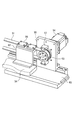
- the drive mechanism 32 is a belt drive system, and includes a timing belt 51 to which the conveyance base 34 is attached via a connecting member 52 and a pair of gear pulleys 53 (drives) around which the timing belt 51 is wound. And a motor 54 that drives the timing belt 51 via one gear pulley 53.
- the gear pulley 53 and the motor 54 are fixed to the base 60 of the inspection system 100 via a support member 55.
- a tooth skip prevention block 57 is provided above and below the gear pulley 53 so as to hold the timing belt 51.
- the connecting member 52 is connected to the upper side of the timing belt 51. As shown in FIG. 3, teeth corresponding to the teeth inside the timing belt 51 are formed on the upper surface of the connecting member 52. Then, the inner part of the timing belt 51 is fitted into the upper surface of the connecting member 52, and the pressing member 56 is screwed from above the timing belt 51 with a screw 58, whereby the timing belt 51 and the connecting member 52 are fixed. .
- the length of the conveyance path 50 is a length of several tens of meters, and the gear pulley 53 and the other gear pulley (not shown).
- the timing belt 51 may become longer and the upper side and the lower side of the timing belt 51 come into contact with each other.
- the connecting member 52 by connecting the connecting member 52 to the upper stage side of the timing belt 51, the upper stage side of the timing belt 51 and the lower side of the conveyance base 34 or the timing belt 51 are suppressed from contacting each other. .
- a sensor unit 71 is provided on the transport base 34 of the loader 31.
- flag portions corresponding to the sensor units 71 are provided. 72 is provided.
- the sensor unit 71 has two position sensors 71 a and 71 b provided in the same direction in the X direction and arranged in the Y direction orthogonal to the X direction.
- two flags 72a and 72b are provided at the same position in the X direction and arranged in the Y direction orthogonal to the X direction.
- the position sensors 71a and 71b are constituted by, for example, optical sensors composed of a light emitting element and a light receiving element.
- the flags 72a and 72b are passed, and when the position sensors 71a and 71b pass the flags 72a and 72b, signals are generated from the position sensors 71a and 71b. Based on this signal, as will be described later, the displacement of the delivery position of the loader 31 due to the lost motion generated when the timing belt 51 is driven is corrected, and the wafer with high accuracy for each inspection apparatus 11 and the pre-alignment unit 22. W can be handed over.
- the reason why two position sensors and two flags are provided is to ensure that the position can be detected even if one position sensor fails.
- the number of position sensors is not limited to two, and may be an appropriate number of two or more. The number of position sensors may be one.
- the loader 31 is connected with a power supply cable and other cables for supplying power to an arm driving mechanism or the like for driving the transfer arm 35. These cables are accommodated in a cable duct 75 as shown in FIG. Connected to a power supply or the like.
- the cable duct 75 has a multi-joint structure and can be bent at an arbitrary position corresponding to the position of the loader 31 in the X direction.
- One end of the cable duct 75 is fixed to the transport base 34 via the attachment member 76, and the other end is fixed at a predetermined position.
- the two roller units 77 are attached to the base 60 at a predetermined interval.
- the number of roller units 77 is not limited to two, and may be an appropriate number of two or more.
- the control unit 40 controls each component constituting the inspection system 100, for example, each inspection device 11, the transport device 30, and the like.
- the main control unit 41 and an input such as a keyboard are provided. It has a device 42, an output device 43 such as a printer, a display device 44, a storage device 45, an external interface 46, and a bus 47 for connecting them together.
- the main control unit 41 has a CPU, a RAM, and a ROM.
- the storage device 45 is for storing information, and reads information stored in a computer-readable storage medium.
- the storage medium is not particularly limited, and a hard disk, an optical disk, a flash memory, or the like is used.
- the main control unit 41 the inspection system 100 is controlled by the CPU executing a program stored in the ROM or the storage device 45.
- the main control unit 41 includes a plurality of control units that control each control unit, and includes a conveyance control unit 81 that controls the conveyance device 30 as one of them.
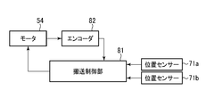
- the conveyance control unit 81 has coordinates in the X direction, which is the conveyance direction of the loader 31 on software, and the coordinates on the delivery positions corresponding to the plurality of inspection apparatuses 11 and the pre-alignment unit 22 respectively. Has position data. As shown in FIG. 8, a signal from an encoder 82 provided in the motor 54 of the drive mechanism 32 is sent to the transport control unit 81, and signals from the position sensors 71a and 71b are sent. The conveyance control unit 81 confirms the position on the coordinates of the loader 31 based on a signal from the encoder 82.
- the position sensors 71a and 71b detect the flags 72a and 72b provided at positions corresponding to the plurality of inspection apparatuses 11 and the pre-alignment unit 22. Each time the signal is received, the position of the loader 31 at the coordinates in the transport control unit 81 is corrected based on the signal.
- the transport control unit 81 also controls the drive mechanism of the transport arm 35, but details thereof are omitted.
- the loader 31 of the transfer device 30 is moved in the X direction to a position corresponding to the hoop placed on the load / unload stage unit 21 of the load / unload unit 20, and the wafer W before inspection from the FOUP F by the transfer arm 35. Take out. Next, the loader 31 is moved in the X direction to the delivery position for the pre-alignment unit 22, and the wafer W on the transfer arm 35 is loaded into the pre-alignment unit 22.
- the wafer W is taken out from the pre-alignment unit 22 by the transfer arm 35, the loader 31 is moved in the X direction to the delivery position for any of the inspection apparatuses 11, and the wafer W on the transfer arm 35 is carried into the inspection apparatus 11. To do.
- the wafer W is mounted on the mounting table, and the probe needle of the probe card is brought into contact with the electrode of the semiconductor device formed on the wafer W, whereby the electrical inspection is performed by the tester via the test head.
- the loader 31 is moved in the X direction to the delivery position for the inspection apparatus 11, the wafer W after the inspection is taken out from the inspection apparatus 11 by the transfer arm 35, and the wafer W is hooped on the loading / unloading stage 31. Return to F.
- the above processing is continuously performed for a plurality of wafers W.
- the loader 31 is moved in the X direction by the drive mechanism 32.
- the position control of the loader 31 at this time is performed by the transport control unit 81 of the control unit 40.
- the transfer control unit 81 has coordinates corresponding to the position of the loader 31, and has position data on the coordinates of the delivery position of the wafer W by the loader 31 for each of the plurality of inspection apparatuses 11 and the pre-alignment unit 22. ing.
- the position control of the X direction of the loader 31 is performed using the position data.
- the belt drive system is employ
- the position sensors 71a and 71b are provided on the conveyance base 34 of the loader 31, and the coordinates of the conveyance control unit 81 are corrected based on the actual positions detected by the position sensors 71a and 71b.
- flags 72a and 72b are respectively provided at predetermined positions corresponding to the plurality of inspection apparatuses 11 and the pre-alignment unit 22, the loader 31 is moved in the X direction, and the position sensors 71a and 71b pass the flags 72a and 72b.
- the conveyance control unit 81 receives the signal, and each time, the position data of the loader 31 on the coordinates in the conveyance control unit 81 is corrected based on the signal, and the shift of the delivery position is corrected.
- FIG. 10 is a flowchart showing the flow at that time
- FIG. 11 is an explanatory diagram for explaining position correction of the delivery position.
- the search start position and the search end position of the position sensors 71a and 71b are set (step 1).
- the search start position and the search end position at this time are, for example, positions 5 mm before and after the flags 72a and 72b as shown in FIG.
- the loader 31 is moved in the X direction, and the search by the position sensors 71a and 71b is executed from the search start position to the search end position (step 2).
- step 3 When the position sensors 71a and 71b detect the flags 72a and 72b, an interrupt signal is received and the position is stored as a teaching position (step 3).
- the distance to the delivery position is stored as a parameter based on the teaching position (step 4).
- the deviation is corrected by correcting the position on the coordinates with the teaching position as a reference. That is, as shown in FIG. 11, the deviation of the design position, which is the position on the software coordinates, is corrected by using the detection position (teaching position) actually detected by the position sensors 71a and 71b as a reference. (Correction amount 1, correction amount 2). Then, the distance from the teaching position to the delivery position is stored as a parameter.
- the design delivery position is corrected for the difference corresponding to the correction value 1 and the correction value 2, and the corrected delivery position is stored and registered (registered delivery position).
- the parameter corresponding to the position sensor 71a is (design value + correction value 1 ⁇ difference)
- the parameter corresponding to the position sensor 71b is (design value + correction value 2 ⁇ difference).
- the interrupt signal of the other position sensor is used to output a message indicating that the position sensor has not been detected.
- a message is also issued if the signal detection positions of both position sensors are shifted.
- the loader position on the coordinates in the transport control unit 81 is corrected based on the positions where the position sensors 71a and 71b actually detect the flags 72a and 72b, so that the transport error (position shift) in the X direction.
- the delivery position of the loader 31 can be set with high accuracy, and the wafer W as the transfer target can be accurately transferred.
- the position on the coordinates of the transport control unit 81 is corrected each time the position sensors 71a and 71b detect the flags 72a and 72b.
- the stroke in the X direction is subdivided, and even if a transport error occurs, the error does not increase.
- This positioning mechanism 90 has a V block 91 fixed to the upper surface of the base 60 and a roller 93 that can be fitted to the V-shaped groove of the V block 91 and can be rotated at the tip, and can be raised and lowered to the transport base 34 of the loader 31 And a drive member 94 for moving the wedge member 92 up and down.
- This positioning mechanism 90 is for setting the delivery position of the loader 31 with high accuracy.
- the roller 93 of the wedge member 92 fits into the V-shaped groove of the V block 91, so that the loader 31 can be placed in an accurate delivery position. Is mechanically positioned. At this time, the position where the roller 93 fits into the V-shaped groove is a position corresponding to a physically highly accurate delivery position in advance.
- FIGS. 13A to 13C The operation of the positioning mechanism 90 is as shown in FIGS. 13A to 13C, for example.
- the loader 31 is in a state before reaching the delivery position, and the wedge member 92 is retracted above the V block 91.
- the loader 31 is transported in the X direction, and the wedge member 92 is lowered at the timing when the wedge member 92 reaches the V block 91 as shown in FIG. 13B.
- the loader 31 is stopped at the above-described registration delivery position by a command from the transport control unit 81, there is a possibility that the registration delivery position is slightly deviated from the actual delivery position.
- the transport device 30 employs a belt drive system as a drive system of the drive mechanism 32 that moves the loader 31 along the transport path 50 in the X direction, the length of the transport path 50 as in the present embodiment.
- the timing belt becomes longer, and the slack of the timing belt 51 increases as shown in FIG.
- the connecting member 52 that connects the conveyance base 34 to the timing belt 51 is often connected to the lower side of the timing belt 51.
- the connecting member 52 is connected to the lower side of the timing belt 51 when the transport stroke is long as described above, the lower side of the timing belt 51 is raised when the loader 31 is moved in the X direction as shown in FIG.
- the upper side and the lower side of the timing belt 51 may come into contact with each other.
- the connecting member 52 is connected to the upper side of the timing belt 51, the upper side and the lower side of the timing belt 51 can be prevented from contacting each other.
- the lower stage side of the timing belt 51 may come into contact with the base 60 due to the deflection of the timing belt 51 due to the longer stroke, but this raises the position of the gear pulley 53 to a position considering the deflection of the timing belt 51. This can be solved.
- the transport path 50 in the X direction of the loader 31 is as long as 10 to 15 m, and the movement stroke in the X direction of the loader 31 becomes long, as shown in FIG.
- the moving stroke of the loader 31 in the X direction is about 9 m
- the cable duct 75 comes into contact with the base 60.
- the two roller units 77 for supporting the cable duct 75 are attached to the base 60, the cable duct 75 contacts the base 60 even when the loader 31 has a large moving stroke. Can be prevented. Thereby, the dust generation by the cable duct 75 contacting the base 60 can be prevented, and the loader 31 can be driven stably.
- the present invention is not limited to the above-described embodiment, and various modifications can be made within the scope of the idea of the present invention.
- a position sensor may be provided at each delivery position on the base side.
- an optical sensor including a light emitting element and a light receiving element is exemplified as the position sensor.
- the position sensor is not limited thereto, and other position sensors such as a proximity sensor and a contact sensor may be used.
- the transfer device is not limited to the inspection system as long as the transfer unit is moved by a belt driving method using a timing belt. Applicable to the system.
- the probe device has been described as an example of the inspection device, but is not limited to the probe device.
- the transferred object is not limited to the semiconductor wafer.
Landscapes
- Engineering & Computer Science (AREA)
- Computer Hardware Design (AREA)
- Microelectronics & Electronic Packaging (AREA)
- General Engineering & Computer Science (AREA)
- Physics & Mathematics (AREA)
- General Physics & Mathematics (AREA)
- Environmental & Geological Engineering (AREA)
- Container, Conveyance, Adherence, Positioning, Of Wafer (AREA)
- Testing Or Measuring Of Semiconductors Or The Like (AREA)
Abstract
ローダー(31)と、ローダー(31)をX方向に沿って移動させ、ウエハWの受け渡しを行う複数の受け渡し位置を有する搬送路(50)と、X方向に配されたタイミングベルト(51)によりローダー(31)を搬送路(50)に沿って移動させるベルト駆動方式の駆動機構(32)と、ローダー(31)が受け渡し位置に対応する所定の位置に達した際に信号を発する位置センサー(71a,71b)と、ローダー(31)を制御する搬送制御部(81)とを有し、搬送制御部(81)は、ローダー(31)の位置に関する座標を有し、位置センサー(71a,71b)からの信号を受け取った際に、その都度その信号に基づいて、搬送制御部(81)における座標上のローダー(31)の位置データを補正する。
Description
本発明は、被搬送体を搬送する搬送装置および搬送方法、ならびに検査システムに関する。
半導体デバイスの製造プロセスでは、半導体ウエハに形成されたICチップの電気的検査が行われる。このような電気的検査を行う検査装置として、一般的に、半導体ウエハに形成された半導体素子の電極にプローブを接触させて電気的検査を行うプローブ装置が用いられる。
このような電気的検査を多数の半導体ウエハに対して効率的に行うため、プローブ装置(検査装置)を複数台並べ、フープ(FOUP)等の収納容器に収納された半導体ウエハを搬送装置により各プローブ装置に搬送する検査システムが提案されている(例えば、特許文献1)。
近時、半導体ウエハの電気的検査のさらなる効率化の観点から、プローブ装置(検査装置)を横方向に10~15台も並べた検査システムも要求されている。
このように検査装置の数が増加すると、半導体ウエハを搬送する搬送装置は、ウエハの受け渡しを行うローダーの横方向の移動距離(ストローク)が最長で十数メートルにも及ぶため、駆動方式として一般的に用いられるボールネジ駆動やリニアモータ駆動の適用は技術的に困難である。
これに対して、タイミングベルトを用いるベルト駆動方式は、このような長い移動距離の搬送に適している。
しかし、タイミングベルトは、十数メートルと長くなると、たるみや伸長の影響があり、ローダーの位置を制御する際に、ソフトウエア上の座標に基づくローダーの位置と、実際のローダーの位置とにズレが生じてしまい、被搬送体である半導体ウエハを正確に搬送できない場合が生じる。
したがって、本発明の目的は、タイミングベルトを用いるベルト駆動方式を採用しても、被搬送体を正確な位置で受け渡すことができる搬送装置および搬送方法、ならびにこのような搬送装置を用いた検査システムを提供することにある。
すなわち、本発明の第1の観点によれば、被搬送体の受け渡しを行うための受け渡し部と、前記受け渡し部を一方向に沿って移動させ、前記受け渡し部による被搬送体の受け渡しを行う複数の受け渡し位置を有する搬送路と、前記一方向に配されたタイミングベルトにより前記受け渡し部を前記搬送路に沿って移動させるベルト駆動方式の駆動機構と、前記受け渡し部が前記受け渡し位置に対応する所定の位置に達した際に信号を発する位置センサーと、前記受け渡し部を制御する制御部とを有し、前記制御部は、前記受け渡し部の位置に関する座標を有しており、前記位置センサーからの前記信号を受け取った際に、その都度その信号に基づいて、前記制御部における前記座標上の前記受け渡し部の位置データを補正することを特徴とする搬送装置が提供される。
前記搬送装置において、前記受け渡し部が前記受け渡し位置の近傍に達した際に、前記受け渡し部を前記受け渡し位置に機械的に位置決めする位置決め機構をさらに有することが好ましい。
前記搬送装置は、前記搬送路の前記受け渡し位置に対応する所定の位置に設けられたフラグをさらに有し、前記位置センサーは前記受け渡し部に設けられ、前記位置センサーが前記フラグに達した際に前記位置センサーから前記信号が発せられる構成とすることができる。
前記位置センサーは前記一方向に直交する方向に複数個配置することができる。
前記受け渡し部は、接続部材を介して前記タイミングベルトに接続されており、前記接続部材は、前記タイミングベルトの上段側に接続されている構成をとることができる。また、前記受け渡し部に接続されるケーブルを収納するケーブルダクトと、前記ケーブルダクトの上段側を支持するローラ部とをさらに有する構成をとることができる。
本発明の第2の観点によれば、被搬送体の受け渡しを行うための受け渡し部と、前記受け渡し部を一方向に沿って移動させ、前記受け渡し部による被搬送体の受け渡しを行う複数の受け渡し位置を有する搬送路と、前記一方向に配されたタイミングベルトにより前記受け渡し部を前記搬送路に沿って移動させるベルト駆動方式の駆動機構と、前記受け渡し部を制御する制御部とを有する搬送装置を用いた搬送方法であって、前記受け渡し部が前記受け渡し位置に対応する所定の位置に達した信号を発する工程と、前記制御部が前記信号を受け取った際に、その都度その信号に基づいて、前記制御部の前記受け渡し部の位置に関する座標上の前記受け渡し部の位置データを補正する工程とを有することを特徴とする搬送方法が提供される。
本発明の第3の観点によれば、一方向に配列され、被検査体の電気的検査を行う複数の検査装置を有する検査ユニットと、前記複数の検査装置に対して被検査体を搬送する搬送装置とを有する検査システムであって、前記搬送装置は、前記複数の検査装置に対して被検査体の受け渡しを行うための受け渡し部と、前記受け渡し部を前記一方向に沿って移動させ、前記受け渡し部と前記検査装置のそれぞれとの間で被検査体の受け渡しを行う複数の受け渡し位置を有する搬送路と、前記一方向に配されたタイミングベルトにより前記受け渡し部を前記搬送路に沿って移動させるベルト駆動方式の駆動機構と、前記受け渡し部が前記受け渡し位置に対応する所定の位置に達した際に信号を発する位置センサーと、前記受け渡し部を制御する制御部とを有し、前記制御部は、前記受け渡し部の位置に関する座標を有しており、前記位置センサーからの前記信号を受け取った際に、その都度その信号に基づいて、前記制御部における前記座標上の前記受け渡し部の位置データを補正することを特徴とする検査システムが提供される。
本発明によれば、受け渡し部を一方向に沿って移動させ、受け渡し部による被搬送体の受け渡しを行う複数の受け渡し位置を有する搬送路に沿って、タイミングベルトにより前記受け渡し部を前記搬送路に沿って移動させるベルト駆動方式の駆動機構により受け渡し部を移動させ、受け渡し部が前記受け渡し位置に対応する所定の位置に達した際にセンサーから発せられた信号を制御部が受け取った際に、その都度その信号に基づいて、制御部における座標上の受け渡し部の位置データを補正する。このため、受け渡し部の移動方向の位置ずれを適宜修正して、受け渡し位置を精度良く設定することができ、被搬送体の正確な搬送を行うことができる。また、複数の受け渡し位置において、位置センサーの検出信号に基づいて、制御部の座標上の位置が補正されるので、受け渡し部の移動方向のストロークが細分化され、たとえ搬送誤差が生じたとしても誤差が大きくならない。
以下、添付図面を参照して本発明の実施の形態について詳細に説明する。
<検査システムの構成>
図1は、本発明の一実施形態に係る検査システムの概略構成を示す平面図である。検査システム100は、被検査体である半導体ウエハ(以下、単にウエハと記す)Wの電気的検査を行うものであり、検査ユニット10と、搬入出ユニット20と、搬送装置30と、制御部40とを有している。
<検査システムの構成>
図1は、本発明の一実施形態に係る検査システムの概略構成を示す平面図である。検査システム100は、被検査体である半導体ウエハ(以下、単にウエハと記す)Wの電気的検査を行うものであり、検査ユニット10と、搬入出ユニット20と、搬送装置30と、制御部40とを有している。
検査ユニット10は、複数、例えば10~15台程度の検査装置11を有し、これらが図中X方向に配列されている。検査装置11は、プローブ装置として構成され、筐体と、その中に設けられたウエハ載置台とを有し、複数のプローブ針(接触子)を有するプローブカードが取り付けられるようになっている。ウエハ載置台は、その上に載置されるウエハをX、Y、Z、θ方向に移動可能となっており、ウエハ載置台を移動させることにより、ウエハに形成された半導体デバイスの電極に対してプローブカードのプローブ針を接触させ、テストヘッドを介してテスターによりウエハWの電気的検査を行うようになっている。
搬入出ユニット20は、ウエハWやプローブカード等の搬入出を行う複数の搬入出ステージを有する搬入出ステージ部21と、ウエハWのプリアライメントを行うプリアライメント部22とを有している。搬入出ステージには、例えばウエハ収納容器であるフープ(FOUP)Fが載置されるようになっている。なお、搬入出ユニット20は、他に、検査後のウエハに対して針跡検査を行う針跡検査装置等を有していてもよい。
搬送装置30は、検査ユニット10の複数の検査装置11およびプリアライメント部22に対してウエハWの受け渡しを行うローダー(受け渡し部)31と、ローダー31を複数の検査装置11の配列方向であるX方向の搬送路50に沿って移動させる駆動機構32と、ローダー31をX方向にガイドするLMガイド33とを有する。
ローダー31は、LMガイド33上をX方向に移動可能な搬送ベース34と、ウエハWを支持し、搬送ベース34に対しY方向、Z方向(上下方向)、θ方向(回転方向)に移動可能な搬送アーム35と、搬送アーム35を駆動するアーム駆動機構(図視せず)と、搬送アーム35が退避状態で搬送アーム35上のウエハWをカバーするカバー部材36とを有している。カバー部材36の内部には乾燥気体が導入されるようになっている。カバー部材36は、搬送アーム35とともにθ方向に回転するようになっている。
搬送装置30は、駆動機構32によりローダー31全体をX方向に移動させ、搬送アーム35により、検査前のウエハWを搬入出ステージ上のフープから取り出してプリアライメント部22に受け渡し、プリアライメント後のウエハWを所定の検査装置11に受け渡すとともに、検査後のウエハWを所定の検査装置11から受け取ってフープ内に収納する。搬送アーム35は一つであっても、2またはそれ以上であってもよい。ローダー31は、複数の検査装置11およびプリアライメント部22のそれぞれに対応する受け渡し位置に停止され、受け渡し位置において搬送アーム35による受け渡し動作が行われる。
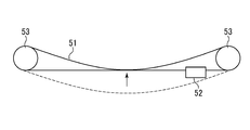
駆動機構32は、図2に示すように、ベルト駆動方式であり、搬送ベース34が連結部材52を介して取り付けられるタイミングベルト51と、タイミングベルト51が巻き掛けられた一対の歯車プーリー53(駆動側のみ図示)と、一方の歯車プーリー53を介してタイミングベルト51を駆動するモーター54とを有している。歯車プーリー53およびモーター54は、支持部材55を介して検査システム100のベース60に固定されている。歯車プーリー53の上下には、タイミングベルト51を押さえるように歯飛び防止ブロック57が設けられている。
連結部材52は、タイミングベルト51の上段側に連結されている。図3に示すように、連結部材52の上面にはタイミングベルト51内側の歯に対応する歯が形成されている。そして、連結部材52の上面にタイミングベルト51の内側部分が嵌め込まれ、タイミングベルト51の上方から押さえ部材56がネジ58によりねじ止めされることにより、タイミングベルト51と連結部材52とが固定される。
検査ユニット10は検査装置11がX方向に10~15台程度配列されて構成されているため、搬送路50の長さは十数メートルの長さとなり、歯車プーリー53と図示しない他方の歯車プーリーの間のタイミングベルト51の長さが長くなってタイミングベルト51の上段側と下段側が接触する危険性がある。しかし、本実施形態では、連結部材52をタイミングベルト51の上段側に連結することにより、タイミングベルト51の上段側と搬送ベース34またはタイミングベルト51の下段側とが接触することを抑制している。
図4に示すように、ローダー31の搬送ベース34にはセンサー部71が設けられている。一方、ベース60の複数の検査装置11に対応する位置およびプリアライメント部22に対応する位置(一部の検査装置11に対応する部分のみ図示)には、センサー部71に対応するようにフラグ部72が設けられている。
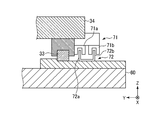
図5に示すように、センサー部71は、X方向の同じ位置に、X方向と直交するY方向に並んで設けられた2つの位置センサー71a,71bを有し、各フラグ部72は、2つの位置センサー71a,71bに対応するように、X方向の同じ位置に、X方向と直交するY方向に並んで設けられた2つのフラグ72a,72bを有している。位置センサー71a,71bは、例えば、発光素子と受光素子からなる光センサーにより構成されており、ローダー31がX方向に移動した際に、センサー部71の位置センサー71a,71bが各フラグ部72のフラグ72a,72bを通過するようになっており、位置センサー71a,71bがフラグ72a,72bを通過した際に、位置センサー71a,71bから信号が発せられるようになっている。この信号に基づき、後述するように、タイミングベルト51を駆動した際に発生するロストモーションによるローダー31の受け渡し位置のズレを補正し、各検査装置11およびプリアライメント部22に対して高精度でウエハWを受け渡しすることができるようになっている。位置センサーおよびフラグが2個ずつ設けられているのは、一つの位置センサーが故障しても確実に位置検出を行えるようにするためである。この場合に、位置センサーの個数は2個に限らず、2個以上の適当な数であればよい。なお、位置センサーは、1個であってもよい。
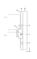
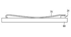
ローダー31には、搬送アーム35を駆動するアーム駆動機構等に給電するための給電ケーブルやその他のケーブルが接続されるが、これらのケーブルは、図6に示すように、ケーブルダクト75に収納された状態で電源等に接続される。ケーブルダクト75は、多関節構造を有しており、ローダー31のX方向位置に対応して任意の位置で折れ曲がり可能となっている。ケーブルダクト75の一端は取り付け部材76を介して搬送ベース34に固定され、他端は所定の位置に固定されている。ローダー31の搬送路50は10~15mと長いため、ローダー31の移動ストロークが大きくなった際にケーブルダクト75の「たれ」によりその上段側がベース60に接触しないように、ケーブルダクト75を支えるためのローラユニット77が2個、所定間隔をおいてベース60に取り付けられている。ローラユニット77は2個に限らず、2個以上の適当な個数であればよい。
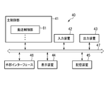
制御部40は、検査システム100を構成する各構成部、例えば、各検査装置11や搬送装置30等を制御するものであり、図7に示すように、主制御部41と、キーボード等の入力装置42と、プリンター等の出力装置43と、表示装置44と、記憶装置45と、外部インターフェース46と、これらを互いに接続するバス47とを有している。主制御部41は、CPU、RAMおよびROMを有している。記憶装置45は、情報を記憶するためのものであり、コンピュータ読み取り可能な記憶媒体に記憶された情報を読み取るようになっている。記憶媒体は特に限定されず、ハードディスク、光ディスク、フラッシュメモリ等が用いられる。主制御部41では、CPUが、ROMまたは記憶装置45に格納されたプログラムを実行することにより検査システム100の制御が行われる。主制御部41は、各制御部の制御を行う複数の制御部を有しており、その一つとして搬送装置30を制御する搬送制御部81を有している。
搬送制御部81は、ソフトウエア上でのローダー31の搬送方向であるX方向の座標を有しており、複数の検査装置11およびプリアライメント部22のそれぞれに対応する受け渡し位置の座標上での位置データを有している。図8に示すように、搬送制御部81には、駆動機構32のモーター54が備えるエンコーダ82の信号が送られ、また、位置センサー71a、71bの信号が送られるようになっている。搬送制御部81は、エンコーダ82からの信号によりローダー31の座標上の位置を確認するようになっている。また、搬送制御部81は、ローダー31をX方向に移動させて、位置センサー71a、71bが複数の検査装置11およびプリアライメント部22に対応する位置に設けられたフラグ72a,72bを検出した際に、その信号を受信し、その都度、その信号に基づいて搬送制御部81内の座標におけるローダー31の位置を補正するようになっている。なお、搬送制御部81は、搬送アーム35の駆動機構も制御するようになっているが、その詳細は省略する。
<検査システムの動作>
次に、以上のように構成される検査システムの動作について、搬送装置の制御を中心に説明する。
最初に、搬送装置30のローダー31を搬入出ユニット20の搬入出ステージ部21に載置されたフープに対応する位置までX方向に移動させ、搬送アーム35によりフープF内から検査前のウエハWを取り出す。次に、ローダー31をプリアライメント部22に対する受け渡し位置までX方向に移動させ、搬送アーム35上のウエハWをプリアライメント部22に搬入する。プリアライメント後、搬送アーム35によりプリアライメント部22からウエハWを取り出し、ローダー31をいずれかの検査装置11に対する受け渡し位置までX方向に移動させ、搬送アーム35上のウエハWを検査装置11に搬入する。
次に、以上のように構成される検査システムの動作について、搬送装置の制御を中心に説明する。
最初に、搬送装置30のローダー31を搬入出ユニット20の搬入出ステージ部21に載置されたフープに対応する位置までX方向に移動させ、搬送アーム35によりフープF内から検査前のウエハWを取り出す。次に、ローダー31をプリアライメント部22に対する受け渡し位置までX方向に移動させ、搬送アーム35上のウエハWをプリアライメント部22に搬入する。プリアライメント後、搬送アーム35によりプリアライメント部22からウエハWを取り出し、ローダー31をいずれかの検査装置11に対する受け渡し位置までX方向に移動させ、搬送アーム35上のウエハWを検査装置11に搬入する。
検査装置11において、ウエハWは載置台に載置され、ウエハWに形成された半導体デバイスの電極にプローブカードのプローブ針を接触させることにより、テストヘッドを介してテスターにより電気的検査が行われる。
ウエハの検査後、ローダー31をその検査装置11に対する受け渡し位置までX方向に移動させ、搬送アーム35によりその検査装置11から検査後のウエハWを取り出し、そのウエハWを搬入出ステージ31上のフープFに戻す。
以上の処理を複数のウエハWについて連続して行う。
以上の処理を複数のウエハWについて連続して行う。
このときのローダー31のX方向の移動は駆動機構32により行われる。このときのローダー31の位置制御は、制御部40の搬送制御部81により行われる。搬送制御部81は、ローダー31の位置に対応した座標を有しており、複数の検査装置11およびプリアライメント部22のそれぞれに対するローダー31によるウエハWの受け渡し位置の座標上の位置データを有している。そして、その位置データを用いてローダー31のX方向の位置制御を行う。
複数の検査装置を有する検査システムは、検査装置が4、5台程度であれば、X方向の駆動方式としてボールネジ駆動やリニアモータ駆動を用いることが一般的であるが、本実施形態のように検査装置11がX方向に10~15台程度配列され、搬送路50の長さは十数メートルとなるためボールネジ駆動やリニアモータ駆動の適用は技術的に困難である。このため、本実施形態では、ローダー31をX方向に駆動する駆動機構32としてベルト駆動方式を採用している。
しかし、ベルト駆動方式により十数メートルに及ぶ長い距離に亘ってローダー31を搬送する場合、タイミングベルト51のたるみや伸長等によるロストモーションの影響があり、搬送制御部81の座標上での位置データとローダー31の実際の位置とがずれてしまう。このため、ローダー31の座標上の検査装置11またはプリアライメント部22に対する受け渡し位置が、本来の受け渡し位置からずれてしまい、図9に示すように、搬送アーム35のズレにより、ウエハWの受け渡しに支障をきたすおそれがある。
そこで、本実施形態では、ローダー31の搬送ベース34に位置センサー71a,71bを設け、搬送制御部81の座標を位置センサー71a,71bにより検出された実際の位置に基づいて補正するようにした。
すなわち、複数の検査装置11およびプリアライメント部22に対応する所定の位置にそれぞれフラグ72a,72bを設け、ローダー31をX方向に移動させて、位置センサー71a,71bがフラグ72a,72bを通過した際に、その信号を搬送制御部81が受信し、その都度、その信号に基づいて搬送制御部81内の座標上のローダー31の位置データを補正し、受け渡し位置のずれを修正する。
このときの搬送制御部81による位置制御について具体的に説明する。
図10はその際のフローを示すフローチャート、図11は受け渡し位置の位置補正を説明するための説明図である。
図10はその際のフローを示すフローチャート、図11は受け渡し位置の位置補正を説明するための説明図である。
最初に、位置センサー71a,71bのサーチ開始位置とサーチ終了位置を設定する(ステップ1)。このときのサーチ開始位置およびサーチ終了位置は、例えば、図11に示すように、フラグ72a,72bの前後5mmの位置とする。
次に、ローダー31をX方向に移動させて、サーチ開始位置からサーチ終了位置まで位置センサー71a,71bによるサーチを実行する(ステップ2)。
そして、位置センサー71a,71bがフラグ72a,72bを検出した際に、割り込み信号を受信し、その位置をティーチング位置として記憶する(ステップ3)。
次に、ティーチング位置を基準として受け渡し位置までの距離をパラメータとして記憶する(ステップ4)。
このとき、タイミングベルトの撓みや伸長の影響により、搬送制御部81が有する座標上のローダー位置と実際のローダー位置とにズレが生じているが、位置センサー71a,71bの実際の検出信号に基づくティーチング位置を基準として、座標上の位置を修正することにより、そのズレが修正される。つまり、図11に示すように、実際に位置センサー71a,71bで検出した検出位置(ティーチング位置)を基準とすることにより、ソフトウエア上の座標での位置である設計位置のズレが補正される(補正量1、補正量2)。そして、ティーチング位置から受け渡し位置までの距離がパラメータとして記憶される。このとき、設計上の受け渡し位置が補正値1および補正値2に対応する差分修正され、その修正された受け渡し位置が記憶され登録される(登録受け渡し位置)。位置センサー71aに対応するパラメータは(設計値+補正値1-差分)であり、位置センサー71bに対応するパラメータは(設計値+補正値2-差分)である。
位置センサー71a,71bのうち一方の割り込み信号が検出されなかった場合は、他方の位置センサーの割り込み信号を使い、検出されなかった位置センサー故障のメッセージを出す。また、両方の位置センサーの信号検出位置がずれていた場合もメッセージを出す。
このようにして、位置センサー71a,71bが実際にフラグ72a,72bを検出した位置に基づいて、搬送制御部81における座標上のローダー位置を補正するので、X方向の搬送誤差(位置のズレ)を適宜修正して、ローダー31の受け渡し位置を精度良く設定することができ、被搬送体であるウエハWの正確な搬送を行うことができる。また、複数の検査装置11およびプリアライメント部22のそれぞれの受け渡し位置おいて、位置センサー71a,71bがフラグ72a,72bを検出する都度、搬送制御部81の座標上の位置が補正されるので、X方向のストロークが細分化され、たとえ搬送誤差が生じたとしても誤差が大きくならない。
また、2個の位置センサー71a,71bを設けることにより、一つの位置センサーが破損したとしても検査システムを停止する必要がなくなり、装置稼働率を低下させることがない。
受け渡し位置をより正確に設定する観点から、図12に示すような位置決め機構を設けることが好ましい。
この位置決め機構90は、ベース60の上面に固定されたVブロック91と、Vブロック91のV字溝に適合可能かつ回転可能なローラ93を先端に有し、ローダー31の搬送ベース34に昇降可能に取り付けられたくさび部材92と、くさび部材92を昇降させる駆動部94とを有する。この位置決め機構90は、ローダー31の受け渡し位置を高精度で設定するためのものであり、くさび部材92のローラ93がVブロック91のV字溝に適合することにより、ローダー31を正確な受け渡し位置に機械的に位置決めするものである。このときV字溝にローラ93が適合した位置が予め物理的に高精度な受け渡し位置に対応する位置である。
位置決め機構90の動作は、例えば、図13A~図13Cに示すようになる。図13Aでは、ローダー31が受け渡し位置に達する前の状態であり、くさび部材92がVブロック91の上方に退避している。ローダー31がX方向に搬送され、図13Bに示すように、くさび部材92がVブロック91に達するタイミングでくさび部材92を降下させる。搬送制御部81からの指令によりローダー31は上述の登録受け渡し位置に停止されるが、この登録受け渡し位置が、実際の受け渡し位置からわずかにずれている可能性がある。
このとき、ローダー31が実際の受け渡し位置からわずかにずれている位置に停止されても、図13Cに示すように、ローラ93がV字溝に沿って移動し、ローダー31を実際の受け渡し位置に正確に位置決めすることができ、高精度の位置決めを実現することができる。
また、搬送装置30においては、ローダー31をX方向の搬送路50に沿って移動させる駆動機構32の駆動方式としてベルト駆動方式を採用しているため、本実施形態のように搬送路50の長さが十数メートルと長くなると、タイミングベルトも長くなり、図14に示すように、タイミングベルト51のたるみが大きくなる。従来は、搬送ベース34をタイミングベルト51に連結する連結部材52はタイミングベルト51の下段側に接続されることが多かった。しかし、このように搬送ストロークが長い場合に、連結部材52をタイミングベルト51の下段側に接続すると、図15に示すように、ローダー31をX方向に移動させる際にタイミングベルト51の下段側が上がり、タイミングベルト51の上段側と下段側が接触するおそれがある。本実施形態では連結部材52をタイミングベルト51の上段側に連結しているので、タイミングベルト51の上段側と下段側が接触することを抑制することができる。また、長ストローク化によるタイミングベルト51の撓みにより、タイミングベルト51の下段側がベース60に接触するおそれがあるが、これは、歯車プーリー53の位置をタイミングベルト51の撓みを考慮した位置に上昇させることにより解消することができる。このようにタイミングベルト51の他所への接触や、タイミングベルト51の上段側と下段側の接触を防止することにより、発塵を防止することができ、また、ローダー31を安定的に走行させることができる。さらに、タイミングベルト51に不所望のテンションがかかることを抑制して、より高精度の位置制御を実現することができる。
さらに、ローダー31のX方向の搬送路50が10~15mと長いことにより、ローダー31のX方向の移動ストロークが長くなると、図16に示すように、ケーブルダクト75の上段側の「たれ量」が大きくなり、例えば、ローダー31のX方向の移動ストロークが9m程度になるとケーブルダクト75がベース60に接触してしまう。これに対し、本実施形態では、ベース60にケーブルダクト75を支えるための2個のローラユニット77を取り付けたので、ローダー31の移動ストロークが大きい場合でも、ケーブルダクト75がベース60に接触することを防止することができる。これにより、ケーブルダクト75がベース60に接触することによる発塵を防止することができ、また、ローダー31を安定的に走行させることができる。
<他の適用>
なお、本発明は上記実施形態に限定されることなく、本発明の思想の範囲内において種々変形可能である。例えば、上記実施形態では、ローダー側に位置センサーを設けた例を示したが、ベース側の各受け渡し位置に位置センサーを設けてもよい。
なお、本発明は上記実施形態に限定されることなく、本発明の思想の範囲内において種々変形可能である。例えば、上記実施形態では、ローダー側に位置センサーを設けた例を示したが、ベース側の各受け渡し位置に位置センサーを設けてもよい。
また、上記実施形態では、位置センサーとして発光素子と受光素子からなる光センサーを例示したが、これに限らず、近接センサー、接触式センサー等他の位置センサーを用いてもよい。
さらに、上記実施形態では、搬送装置を検査システムに適用した場合について示したが、タイミングベルトを用いたベルト駆動方式により受け渡し部を移動させるものであれば、検査システムに限るものではなく、種々のシステムに適用可能である。
さらにまた、上記実施形態では、検査装置としてプローブ装置を例にとって説明したが、プローブ装置に限るものではない。
さらにまた、上記実施形態では、被搬送体として半導体ウエハを用いた例を示したが、被搬送体は半導体ウエハに限るものではない。
10;検査ユニット、20;搬入出ユニット、22;プリアライメント部、30;搬送装置、31;ローダー、32;駆動機構、33;LMガイド、34;搬送ベース、35;搬送アーム、40;制御部、41;主制御部、50;搬送路、51;タイミングベルト、52;連結部材、53;歯車プーリー、54;モーター、55;支持部材、60;ベース、71;センサー部、71a,71b;位置センサー、72;フラグ部、72a,72b;フラグ、75;ケーブルダクト、77;ローラユニット、81;搬送制御部、90;位置決め機構、91;Vブロック、92;くさび部材、93;ローラ、100;検査システム、W;半導体ウエハ(被搬送体)
Claims (14)
- 被搬送体の受け渡しを行うための受け渡し部と、
前記受け渡し部を一方向に沿って移動させ、前記受け渡し部による被搬送体の受け渡しを行う複数の受け渡し位置を有する搬送路と、
前記一方向に配されたタイミングベルトにより前記受け渡し部を前記搬送路に沿って移動させるベルト駆動方式の駆動機構と、
前記受け渡し部が前記受け渡し位置に対応する所定の位置に達した際に信号を発する位置センサーと、
前記受け渡し部を制御する制御部と
を有し、
前記制御部は、前記受け渡し部の位置に関する座標を有しており、前記位置センサーからの前記信号を受け取った際に、その都度その信号に基づいて、前記制御部における前記座標上の前記受け渡し部の位置データを補正することを特徴とする搬送装置。 - 前記受け渡し部が前記受け渡し位置の近傍に達した際に、前記受け渡し部を前記受け渡し位置に機械的に位置決めする位置決め機構をさらに有することを特徴とする請求項1に記載の搬送装置。
- 前記搬送路の前記受け渡し位置に対応する所定の位置に設けられたフラグをさらに有し、前記位置センサーは前記受け渡し部に設けられ、前記位置センサーが前記フラグに達した際に前記位置センサーから前記信号が発せられることを特徴とする請求項1または請求項2に記載の搬送装置。
- 前記位置センサーは前記一方向に直交する方向に複数個配置されていることを特徴とする請求項1から請求項3のいずれか1項に記載の搬送装置。
- 前記受け渡し部は、接続部材を介して前記タイミングベルトに接続されており、前記接続部材は、前記タイミングベルトの上段側に接続されていることを特徴とする請求項1から請求項4のいずれか1項に記載の搬送装置。
- 前記受け渡し部に接続されるケーブルを収納するケーブルダクトと、前記ケーブルダクトの上段側を支持するローラ部とをさらに有することを特徴とする請求項1から請求項5のいずれか1項に記載の搬送装置。
- 被搬送体の受け渡しを行うための受け渡し部と、前記受け渡し部を一方向に沿って移動させ、前記受け渡し部による被搬送体の受け渡しを行う複数の受け渡し位置を有する搬送路と、前記一方向に配されたタイミングベルトにより前記受け渡し部を前記搬送路に沿って移動させるベルト駆動方式の駆動機構と、前記受け渡し部を制御する制御部とを有する搬送装置を用いた搬送方法であって、
前記受け渡し部が前記受け渡し位置に対応する所定の位置に達した信号を発する工程と、
前記制御部が前記信号を受け取った際に、その都度その信号に基づいて、前記制御部の前記受け渡し部の位置に関する座標上の前記受け渡し部の位置データを補正する工程と
を有することを特徴とする搬送方法。 - 前記受け渡し部が前記受け渡し位置の近傍に達した際に、前記受け渡し部を前記受け渡し位置に機械的に位置決めすることを特徴とする請求項7に記載の搬送方法。
- 一方向に配列され、被検査体の電気的検査を行う複数の検査装置を有する検査ユニットと、
前記複数の検査装置に対して被検査体を搬送する搬送装置と
を有する検査システムであって、
前記搬送装置は、
前記複数の検査装置に対して被検査体の受け渡しを行うための受け渡し部と、
前記受け渡し部を前記一方向に沿って移動させ、前記受け渡し部と前記検査装置のそれぞれとの間で被検査体の受け渡しを行う複数の受け渡し位置を有する搬送路と、
前記一方向に配されたタイミングベルトにより前記受け渡し部を前記搬送路に沿って移動させるベルト駆動方式の駆動機構と、
前記受け渡し部が前記受け渡し位置に対応する所定の位置に達した際に信号を発する位置センサーと、
前記受け渡し部を制御する制御部と
を有し、
前記制御部は、前記受け渡し部の位置に関する座標を有しており、前記位置センサーからの前記信号を受け取った際に、その都度その信号に基づいて、前記制御部における前記座標上の前記受け渡し部の位置データを補正することを特徴とする検査システム。 - 前記受け渡し部が前記受け渡し位置の近傍に達した際に、前記受け渡し部を前記受け渡し位置に機械的に位置決めする位置決め機構をさらに有することを特徴とする請求項9に記載の検査システム。
- 前記搬送装置は、前記搬送路の前記受け渡し位置に対応する所定の位置に設けられたフラグをさらに有し、前記位置センサーは前記受け渡し部に設けられ、前記位置センサーが前記フラグに達した際に前記位置センサーから前記信号が発せられることを特徴とする請求項9または請求項10に記載の検査システム。
- 前記位置センサーは前記一方向に直交する方向に複数個配置されていることを特徴とする請求項9から請求項11のいずれか1項に記載の検査システム。
- 前記受け渡し部は、接続部材を介して前記タイミングベルトに接続されており、前記接続部材は、前記タイミングベルトの上段側に接続されていることを特徴とする請求項9から請求項12のいずれか1項に記載の検査システム。
- 前記受け渡し部に接続されるケーブルを収納するケーブルダクトと、前記ケーブルダクトの上段側を支持するローラ部とをさらに有することを特徴とする請求項9から請求項13のいずれか1項に記載の検査システム。
Priority Applications (2)
| Application Number | Priority Date | Filing Date | Title |
|---|---|---|---|
| US16/311,499 US20190189482A1 (en) | 2016-06-20 | 2017-05-11 | Transfer device, transfer method, and inspection system |
| KR1020187036661A KR102157949B1 (ko) | 2016-06-20 | 2017-05-11 | 반송 장치 및 반송 방법, 그리고 검사 시스템 |
Applications Claiming Priority (2)
| Application Number | Priority Date | Filing Date | Title |
|---|---|---|---|
| JP2016-121585 | 2016-06-20 | ||
| JP2016121585A JP6615698B2 (ja) | 2016-06-20 | 2016-06-20 | 搬送装置および搬送方法、ならびに検査システム |
Publications (1)
| Publication Number | Publication Date |
|---|---|
| WO2017221576A1 true WO2017221576A1 (ja) | 2017-12-28 |
Family
ID=60784053
Family Applications (1)
| Application Number | Title | Priority Date | Filing Date |
|---|---|---|---|
| PCT/JP2017/017857 Ceased WO2017221576A1 (ja) | 2016-06-20 | 2017-05-11 | 搬送装置および搬送方法、ならびに検査システム |
Country Status (5)
| Country | Link |
|---|---|
| US (1) | US20190189482A1 (ja) |
| JP (1) | JP6615698B2 (ja) |
| KR (1) | KR102157949B1 (ja) |
| TW (1) | TW201804550A (ja) |
| WO (1) | WO2017221576A1 (ja) |
Families Citing this family (2)
| Publication number | Priority date | Publication date | Assignee | Title |
|---|---|---|---|---|
| JP7453823B2 (ja) * | 2020-03-23 | 2024-03-21 | 東京エレクトロン株式会社 | 基板処理装置及び基板処理方法 |
| CN116984167B (zh) * | 2023-09-26 | 2023-11-28 | 四川富士电机有限公司 | 一种雨刮支架表面喷涂设备 |
Citations (3)
| Publication number | Priority date | Publication date | Assignee | Title |
|---|---|---|---|---|
| JPH07161632A (ja) * | 1993-07-16 | 1995-06-23 | Semiconductor Syst Inc | 基板コーティング/現像システム用熱処理モジュール |
| JP2001088067A (ja) * | 1999-09-27 | 2001-04-03 | Ando Electric Co Ltd | オートハンドラ、その制御方法、及び記憶媒体 |
| JP2002308420A (ja) * | 2001-04-10 | 2002-10-23 | Canon Inc | ガラス基板の位置決め装置 |
Family Cites Families (6)
| Publication number | Priority date | Publication date | Assignee | Title |
|---|---|---|---|---|
| JPH11154697A (ja) * | 1997-11-20 | 1999-06-08 | Dainippon Screen Mfg Co Ltd | 基板処理装置およびバックラッシ量の測定方法 |
| JP4757288B2 (ja) * | 2008-08-28 | 2011-08-24 | 株式会社椿本チエイン | ケーブル保護案内装置用ガイドレール |
| JP5045705B2 (ja) * | 2009-04-16 | 2012-10-10 | 村田機械株式会社 | 搬送車システム |
| JP5952645B2 (ja) | 2012-06-06 | 2016-07-13 | 東京エレクトロン株式会社 | ウエハ検査用インターフェース及びウエハ検査装置 |
| JP6400412B2 (ja) * | 2014-09-29 | 2018-10-03 | 東京エレクトロン株式会社 | 搬送方法及び検査システム |
| KR102587203B1 (ko) * | 2015-07-13 | 2023-10-10 | 브룩스 오토메이션 인코퍼레이티드 | 온 더 플라이 자동 웨이퍼 센터링 방법 및 장치 |
-
2016
- 2016-06-20 JP JP2016121585A patent/JP6615698B2/ja active Active
-
2017
- 2017-05-11 KR KR1020187036661A patent/KR102157949B1/ko active Active
- 2017-05-11 WO PCT/JP2017/017857 patent/WO2017221576A1/ja not_active Ceased
- 2017-05-11 US US16/311,499 patent/US20190189482A1/en not_active Abandoned
- 2017-06-13 TW TW106119663A patent/TW201804550A/zh unknown
Patent Citations (3)
| Publication number | Priority date | Publication date | Assignee | Title |
|---|---|---|---|---|
| JPH07161632A (ja) * | 1993-07-16 | 1995-06-23 | Semiconductor Syst Inc | 基板コーティング/現像システム用熱処理モジュール |
| JP2001088067A (ja) * | 1999-09-27 | 2001-04-03 | Ando Electric Co Ltd | オートハンドラ、その制御方法、及び記憶媒体 |
| JP2002308420A (ja) * | 2001-04-10 | 2002-10-23 | Canon Inc | ガラス基板の位置決め装置 |
Also Published As
| Publication number | Publication date |
|---|---|
| KR102157949B1 (ko) | 2020-09-18 |
| US20190189482A1 (en) | 2019-06-20 |
| JP6615698B2 (ja) | 2019-12-04 |
| KR20190008358A (ko) | 2019-01-23 |
| JP2017228557A (ja) | 2017-12-28 |
| TW201804550A (zh) | 2018-02-01 |
Similar Documents
| Publication | Publication Date | Title |
|---|---|---|
| JP5641889B2 (ja) | スプライシング誤作業防止方法 | |
| US7940065B2 (en) | Probe apparatus and method for measuring electrical characteristics of chips | |
| KR101485297B1 (ko) | 열처리 장치 및 기판 반송 위치 조정 방법 | |
| KR102538850B1 (ko) | 산업용 로봇 | |
| KR101752765B1 (ko) | 전자부품 실장장치 | |
| KR101915878B1 (ko) | 기판 주고받음 위치의 교시 방법 및 기판 처리 시스템 | |
| CN108364898A (zh) | 基板搬送装置、检测位置校正方法及基板处理装置 | |
| CN103247560A (zh) | 基板处理装置、基板处理方法和存储介质 | |
| CN102738038A (zh) | 臂型搬运装置 | |
| CN104723362A (zh) | 机器人系统及检测方法 | |
| WO2015083211A1 (ja) | 電子部品搬送装置 | |
| TWI468709B (zh) | Electronic components operating device and its application of detection equipment | |
| JP2013191741A (ja) | プローブ装置及びプローブ装置のプローブカード装着方法 | |
| JP2007088286A (ja) | 基板搬送システム、基板搬送装置、基板搬送方法及び記憶媒体 | |
| JP5309503B2 (ja) | 位置決め装置と、位置決め方法と、これらを有する半導体製造装置 | |
| JP6615698B2 (ja) | 搬送装置および搬送方法、ならびに検査システム | |
| JP6884191B2 (ja) | 搬送装置および検査システム | |
| JP4927776B2 (ja) | 部品実装方法 | |
| JP6832654B2 (ja) | 検査システムの調整方法およびそれに用いる補助エレメント | |
| JP4620745B2 (ja) | 部品撮像装置、表面実装機および部品試験装置 | |
| JP2008066630A (ja) | 基板搬送装置及びそれを備えた印刷はんだ検査装置 | |
| JP6928527B2 (ja) | 高さ測定装置、高さ測定方法および基板作業装置 | |
| JP7780739B2 (ja) | 部品装着装置、補正データの生成方法および部品装着システム | |
| JP5761772B1 (ja) | 電子部品搬送装置 | |
| JPH112789A (ja) | 液晶表示装置用絶縁性基板の位置決め方法および液晶表示装置用絶縁性基板移載装置 |
Legal Events
| Date | Code | Title | Description |
|---|---|---|---|
| 121 | Ep: the epo has been informed by wipo that ep was designated in this application |
Ref document number: 17815046 Country of ref document: EP Kind code of ref document: A1 |
|
| ENP | Entry into the national phase |
Ref document number: 20187036661 Country of ref document: KR Kind code of ref document: A |
|
| NENP | Non-entry into the national phase |
Ref country code: DE |
|
| 122 | Ep: pct application non-entry in european phase |
Ref document number: 17815046 Country of ref document: EP Kind code of ref document: A1 |