WO2017183487A1 - 金属粉末の製造方法 - Google Patents
金属粉末の製造方法 Download PDFInfo
- Publication number
- WO2017183487A1 WO2017183487A1 PCT/JP2017/014531 JP2017014531W WO2017183487A1 WO 2017183487 A1 WO2017183487 A1 WO 2017183487A1 JP 2017014531 W JP2017014531 W JP 2017014531W WO 2017183487 A1 WO2017183487 A1 WO 2017183487A1
- Authority
- WO
- WIPO (PCT)
- Prior art keywords
- gas
- metal
- particles
- silicon
- metal chloride
- Prior art date
Links
Images


Classifications
-
- B—PERFORMING OPERATIONS; TRANSPORTING
- B22—CASTING; POWDER METALLURGY
- B22F—WORKING METALLIC POWDER; MANUFACTURE OF ARTICLES FROM METALLIC POWDER; MAKING METALLIC POWDER; APPARATUS OR DEVICES SPECIALLY ADAPTED FOR METALLIC POWDER
- B22F9/00—Making metallic powder or suspensions thereof
- B22F9/16—Making metallic powder or suspensions thereof using chemical processes
- B22F9/18—Making metallic powder or suspensions thereof using chemical processes with reduction of metal compounds
- B22F9/28—Making metallic powder or suspensions thereof using chemical processes with reduction of metal compounds starting from gaseous metal compounds
-
- B—PERFORMING OPERATIONS; TRANSPORTING
- B22—CASTING; POWDER METALLURGY
- B22F—WORKING METALLIC POWDER; MANUFACTURE OF ARTICLES FROM METALLIC POWDER; MAKING METALLIC POWDER; APPARATUS OR DEVICES SPECIALLY ADAPTED FOR METALLIC POWDER
- B22F1/00—Metallic powder; Treatment of metallic powder, e.g. to facilitate working or to improve properties
- B22F1/05—Metallic powder characterised by the size or surface area of the particles
-
- C—CHEMISTRY; METALLURGY
- C01—INORGANIC CHEMISTRY
- C01B—NON-METALLIC ELEMENTS; COMPOUNDS THEREOF; METALLOIDS OR COMPOUNDS THEREOF NOT COVERED BY SUBCLASS C01C
- C01B33/00—Silicon; Compounds thereof
- C01B33/02—Silicon
- C01B33/021—Preparation
- C01B33/027—Preparation by decomposition or reduction of gaseous or vaporised silicon compounds other than silica or silica-containing material
- C01B33/03—Preparation by decomposition or reduction of gaseous or vaporised silicon compounds other than silica or silica-containing material by decomposition of silicon halides or halosilanes or reduction thereof with hydrogen as the only reducing agent
-
- B—PERFORMING OPERATIONS; TRANSPORTING
- B22—CASTING; POWDER METALLURGY
- B22F—WORKING METALLIC POWDER; MANUFACTURE OF ARTICLES FROM METALLIC POWDER; MAKING METALLIC POWDER; APPARATUS OR DEVICES SPECIALLY ADAPTED FOR METALLIC POWDER
- B22F2201/00—Treatment under specific atmosphere
- B22F2201/01—Reducing atmosphere
- B22F2201/013—Hydrogen
-
- B—PERFORMING OPERATIONS; TRANSPORTING
- B22—CASTING; POWDER METALLURGY
- B22F—WORKING METALLIC POWDER; MANUFACTURE OF ARTICLES FROM METALLIC POWDER; MAKING METALLIC POWDER; APPARATUS OR DEVICES SPECIALLY ADAPTED FOR METALLIC POWDER
- B22F2201/00—Treatment under specific atmosphere
- B22F2201/40—Metal compounds
-
- B—PERFORMING OPERATIONS; TRANSPORTING
- B22—CASTING; POWDER METALLURGY
- B22F—WORKING METALLIC POWDER; MANUFACTURE OF ARTICLES FROM METALLIC POWDER; MAKING METALLIC POWDER; APPARATUS OR DEVICES SPECIALLY ADAPTED FOR METALLIC POWDER
- B22F2304/00—Physical aspects of the powder
- B22F2304/05—Submicron size particles
- B22F2304/056—Particle size above 100 nm up to 300 nm
-
- B—PERFORMING OPERATIONS; TRANSPORTING
- B22—CASTING; POWDER METALLURGY
- B22F—WORKING METALLIC POWDER; MANUFACTURE OF ARTICLES FROM METALLIC POWDER; MAKING METALLIC POWDER; APPARATUS OR DEVICES SPECIALLY ADAPTED FOR METALLIC POWDER
- B22F2998/00—Supplementary information concerning processes or compositions relating to powder metallurgy
- B22F2998/10—Processes characterised by the sequence of their steps
-
- C—CHEMISTRY; METALLURGY
- C01—INORGANIC CHEMISTRY
- C01P—INDEXING SCHEME RELATING TO STRUCTURAL AND PHYSICAL ASPECTS OF SOLID INORGANIC COMPOUNDS
- C01P2004/00—Particle morphology
- C01P2004/01—Particle morphology depicted by an image
- C01P2004/03—Particle morphology depicted by an image obtained by SEM
-
- C—CHEMISTRY; METALLURGY
- C01—INORGANIC CHEMISTRY
- C01P—INDEXING SCHEME RELATING TO STRUCTURAL AND PHYSICAL ASPECTS OF SOLID INORGANIC COMPOUNDS
- C01P2004/00—Particle morphology
- C01P2004/30—Particle morphology extending in three dimensions
- C01P2004/32—Spheres
-
- C—CHEMISTRY; METALLURGY
- C01—INORGANIC CHEMISTRY
- C01P—INDEXING SCHEME RELATING TO STRUCTURAL AND PHYSICAL ASPECTS OF SOLID INORGANIC COMPOUNDS
- C01P2004/00—Particle morphology
- C01P2004/60—Particles characterised by their size
- C01P2004/62—Submicrometer sized, i.e. from 0.1-1 micrometer
-
- C—CHEMISTRY; METALLURGY
- C01—INORGANIC CHEMISTRY
- C01P—INDEXING SCHEME RELATING TO STRUCTURAL AND PHYSICAL ASPECTS OF SOLID INORGANIC COMPOUNDS
- C01P2004/00—Particle morphology
- C01P2004/60—Particles characterised by their size
- C01P2004/64—Nanometer sized, i.e. from 1-100 nanometer
-
- C—CHEMISTRY; METALLURGY
- C01—INORGANIC CHEMISTRY
- C01P—INDEXING SCHEME RELATING TO STRUCTURAL AND PHYSICAL ASPECTS OF SOLID INORGANIC COMPOUNDS
- C01P2004/00—Particle morphology
- C01P2004/80—Particles consisting of a mixture of two or more inorganic phases
-
- C—CHEMISTRY; METALLURGY
- C01—INORGANIC CHEMISTRY
- C01P—INDEXING SCHEME RELATING TO STRUCTURAL AND PHYSICAL ASPECTS OF SOLID INORGANIC COMPOUNDS
- C01P2006/00—Physical properties of inorganic compounds
- C01P2006/12—Surface area
Definitions
- the present invention relates to a novel method for producing a metal powder having a large surface area composed of fine metal particles.
- metal powders composed of fine metal particles and having a large specific surface area are used or proposed for various applications including capacitors and lithium-ion electrode materials.
- a method for producing a metal powder having a large specific surface area composed of such fine metal particles As a method for producing a metal powder having a large specific surface area composed of such fine metal particles, a method of depositing a metal in a liquid containing a metal source material (called a wet method or a hydrothermal method) is known.
- a wet method when particles smaller than 1 micron are collected, it takes a long time and the yield is also lowered, so that the cost is extremely increased.
- the method of obtaining metal powder composed of fine particles using plasma is extremely expensive, and the metal powder that is inevitably obtained is very expensive, making it difficult to put it to practical industrial use. .
- Example 1 of Patent Document 1 an average primary particle size of about 60 nm is obtained by introducing a silicon (Si) source material (micron-sized Si powder) into an argon plasma to vaporize and then cooling. It describes that the Si powder which has it is manufactured. However, it is difficult to obtain a metal powder having a low oxygen content by the method using plasma.
- Ar gas is used as an inert gas of the plasma source, and a method of supplying a metal source into the Ar plasma is adopted. This is because about 100 ppm of oxygen is unavoidably present, so that it is not possible to avoid mixing oxygen into the resulting metal powder.
- metal powder when metal powder is produced by such a method, there is a problem that it is oxidized in the reactor during the reaction for forming particles.
- silicon powder since silicon powder is very easily oxidized compared to other metal powders, even if extremely high purity Ar gas is used, the oxygen content is low at the reactor outlet, but the way the particles are put into the air. It is covered with an oxide film of 5 nm or more in a very short time. At this time, heat generation due to oxidation leads to self-ignition and explosion, so silicon fine particles are recognized as a very dangerous flammable solid.
- the oxygen content of the Si powder obtained in Example 1 of Patent Document 1 is 2.8% by mass.
- the surface area of the silicon particles is 30 m 2 / g, all oxygen is calculated by simple calculation. Even if it is assumed that exists on the surface, the oxide film thickness is about 1.2 nm. Therefore, it is estimated that the surface of this particle is still very active. That is, since silicon is a substance that is very easily oxidized, its surface is oxidized as soon as it comes into contact with air, and is instantly covered with an oxide film of about 5 nm in dry air.
- the thickness of the oxide film reaches about 5 nm, the supply of oxygen from the outside decreases, so that the surface oxidation reaction gradually stops, and the growth of the oxide film stops at about 10 nm if it is dry at room temperature.
- the oxide film becomes thicker and may grow to several hundred nm.
- Analysis of typical silicon particles with a specific surface area of 22 m 2 / g prepared by the plasma method on the market revealed an oxygen concentration of 18% and an oxide film thickness conversion (apparent oxide film thickness) of 8 nm. Met. Since such particles do not explode even if they are released into the air, they are distributed in the market as flammable fixed but relatively safe particles.
- Patent Document 2 discloses that silicon chloride is used as a silicon source and hydrogen gas is used as a reducing gas.
- a method for producing metallic silicon by gas phase reduction is disclosed.
- CVD method chemical vapor deposition method
- film growth on the metal surface is repeated, and a product is obtained as a large solid.
- the nucleation is not likely to occur and is not applied to the production of metal powders composed of fine particles.
- metallic silicon is deposited on the wall surface of the reactor and melted and dropped to obtain metallic silicon.
- Patent Document 3 discloses that metal zinc is gasified, mixed with zinc gas and silicon tetrachloride, and turbulently flows in a tubular body maintained at 1050 ° C. to 1250 ° C.
- a method for producing fine particles has been proposed. Silicon particles can be produced with this technique, but when silicon tetrachloride and zinc are supplied as gases, the volume of the gas is greatly reduced before and after the reaction, and the system is under negative pressure.
- the operation is batch operation, or a continuous process is performed while maintaining the pressure balance of the process by supplying silicon tetrachloride as a liquid. A way to do it has been proposed.
- easily decomposed gases such as monosilane and monochlorosilane have a large number of molecules on the surface that enhance the adhesion between particles such as SiH 2 and SiH 3. Since it grows, only large particles of about several hundred nanometers can be obtained, and as a result, a powder having a large specific surface area cannot be obtained.
- Patent No. 5618113 Japanese Patent No. 5258339 Japanese Patent No. 5533601
- the object of the present invention is to produce a metal powder that has a small content of oxygen and other impurities immediately after production, has a large specific surface area, and does not easily oxidize even when left in the air, using inexpensive means without using plasma. It is to provide a way to do.
- Another object of the present invention is to provide a silicon powder obtained by the above method.
- a preparation step of preparing a metal chloride gas and a reducing gas A gas phase reduction step of generating metal particles in the gas stream by a gas phase reduction reaction in which the metal chloride gas and the reducing gas are contact-mixed; A collecting step of collecting metal particles from the gas flow after the gas phase reduction reaction to obtain metal powder;
- the metal chloride gas and the reducing gas are heated separately, and the metal chloride gas is kept below the thermal decomposition temperature of the metal chloride,
- the temperature of the mixed gas of the metal chloride gas and the reducing gas is made to reach or exceed the temperature at which the gas phase reduction reaction occurs,
- the metal powder obtained in the collecting step has a BET specific surface area of 5 to 250 m 2 / g, and a method for producing a metal powder is provided.
- the following means can be preferably employed.
- (1) In the gas phase reduction step after the metal chloride gas and the reducing gas are contacted, the reacted gas is immediately cooled.
- (2) In the preparation step by using a multi-pipe, supplying a metal chloride gas to at least one pipe of the multi-pipe and supplying a reducing gas to at least one other pipe of the multi-pipe. The heating of the metal chloride gas and the heating of the reducing gas are performed separately in the multiple tube.
- a gas phase reduction reaction is performed by contact of the metal chloride gas and the reducing gas at the gas outlet of the multiple pipe.
- the reducing gas is hydrogen gas.
- the following means can be suitably employed. (5) Using silicon chloride as the metal chloride and obtaining silicon powder as the metal powder. (6) The silicon chloride is trichlorosilane or silicon tetrachloride. (7) After collecting the metal particles contained in the gas flow after the reaction, hydrogen gas is separated from the gas flow, and the separated hydrogen gas is supplied to the preparation step. (8) After collecting the metal particles generated from the gas stream after the reaction, hydrogen gas and metal chloride containing metal particles are separated from the gas stream, and then included in the separated metal chloride After recovering the metal particles, supplying the metal chloride to the preparation step.
- apparent oxidation is measured after standing for 24 hours in air at a normal temperature, normal pressure, and humidity of 50% by the above-described method and having a BET specific surface area of 5 to 250 m 2 / g. Silicon powder having a film thickness of less than 5 nm is obtained.
- a metal powder having a large specific surface area with a BET specific surface area in the range of 5 to 250 m 2 / g can be obtained. That is, since the production method of the present invention is a dry method, the separation of particles is easy and the yield is high, and since no plasma is used, there is no need to use a special apparatus, resulting in a significant cost reduction. This is the greatest advantage of the present invention.
- the obtained metal powder is oxidized even when it comes into contact with air. It is hard to be done.
- silicon chloride is used as the metal chloride and hydrogen gas is used as the reducing gas
- the resulting silicon powder not only has a large BET specific surface area as described above, but also has such a large specific surface area. Even if it has, it is hard to be oxidized even if it is left in the air, and can be handled safely. Such a silicon powder has not been known so far.
- the metal powder obtained by the present invention particularly silicon powder, has the property that it is difficult to oxidize in the air is shown in the examples described later, for the reason, the present inventors, Estimated as follows. That is, the silicon powder obtained by the production method of the present invention is considered that many of the silicon particle surfaces constituting the powder are terminated with chlorine, and considering the atomic size ratio of hydrogen and chlorine, In reality, it is considered that most of the surface is covered with large chlorine atoms and double bonds between silicon crushed by chlorine. Because of this effect, the metal particles produced by the production method of the present invention (SNN method) have a large specific surface area and are difficult to react with oxygen. It is done.
- the silicon powder and the aggregate thereof as described above have greatly improved crackability due to the size of the primary particles, and further Si—O-based negative electrode materials.
- the trapping and deactivation of lithium ions by oxygen is also reduced, so that it is suitably used as a negative electrode material active material for lithium ion secondary batteries.
- FIG. 4 is an electron micrograph of silicon particles obtained in Example 1.
- FIG. 4 is an electron micrograph of silicon particles obtained in Example 2.
- FIG. 4 is an electron micrograph of silicon particles obtained in Example 3.
- FIG. 4 is an electron micrograph of silicon particles obtained in Comparative Example 2.
- FIG. 4 is an electron micrograph of silicon particles obtained in Comparative Example 2.
- the method for producing metal powder by the SNN method adopted by the present invention is roughly described as follows: A preparatory step of preparing separately heated metal chloride gas and reducing gas; A gas phase reduction step of generating metal particles in the gas stream by a gas phase reduction reaction in which the metal chloride gas and the reducing gas are contact-mixed; A collecting step of collecting metal particles from the gas flow after the gas phase reduction reaction to obtain metal powder;
- A) In the preparation step the metal salt gas and the reducing gas are separately heated, but the metal chloride gas should be kept below the thermal decomposition temperature of the metal chloride.
- the metal chloride gas heated as described above is brought into contact with the reducing gas so that the temperature of the mixed gas reaches or exceeds the temperature at which the gas phase reduction reaction occurs. That is, at least one of the metal chloride gas and the reducing gas is heated above the temperature at which the gas-phase reduction reaction occurs (above the metal nucleation temperature), so that the metal chloride gas-phase reduction reaction is performed. Do it instantly.
- By contacting and mixing these gases heated to such a temperature fine metal particles are produced simultaneously with the mixing, and the fine metal particles are aggregated or collected as they are without growing the particles. As a result, a desired metal powder having a large BET specific surface area can be obtained.
- the source gas is decomposed by the CVD reaction on the surface of the nuclei particles, and a solid is deposited in the form of a film.
- the temperature region in the conventionally known melt deposition method (VLD method) or silicon manufacturing method by the Siemens method is in the region of the CVD zone.
- the metal salt compound gas that serves as the metal source and the reducing gas are separately heated in advance, and the temperature of the mixed gas at the time of contact mixing of the two gases is adjusted to that of the metal by the gas phase reduction reaction.
- the temperature above the nucleation temperature not only instantly a large amount of nuclei particles are generated, but also the metal chloride used as a raw material for CVD is used up instantaneously, effectively avoiding particle growth and coalescence.
- the present inventors have succeeded in obtaining a metal powder having a large BET specific surface area composed of particles.
- the temperature of the mixed gas flow when contacting and mixing is above the “ideal particle formation temperature range”, that is, above the metal nucleation temperature by the gas phase reduction reaction.
- the metal salt compound gas and the reducing gas are separately heated to a predetermined temperature so as to be in a temperature region below the melting point of the metal.
- the heating of the metal chloride gas and the reducing gas only needs to be within the ideal particle formation temperature range during contact mixing, and even if the heating temperature of one gas is low, the other gas is sufficiently heated.
- an embodiment in which both gases are heated to a temperature in the above temperature range is most preferable.
- the ideal particle formation temperature range varies depending on the type of metal to be generated, and cannot be generally limited.
- nucleation occurs efficiently at 1100 ° C. or higher and below 1400 ° C. below the melting point of silicon.
- the following is preferable, and more preferable is that silicon chloride is moderately separated and silylene (SiCl 2 ), which is a source of nucleation, is considered to start to be generated at a temperature higher than 1150 ° C. 1350 ° C. or less is recommended.
- the reaction between the metal chloride serving as the metal source and the reducing gas is performed without going through the particle growth zone. Moreover, not only instantly a large number of fine particles that become nuclei are generated, but also the core particles are carried without stagnation of the gas flow, so the concentration of the metal source around the generated particles becomes dilute and newly supplied. There is no increase in diameter due to the metal chloride gas produced. Further, the diameter reduction due to the etching of the particles by by-product hydrogen chloride can be effectively suppressed by the subsequent temperature drop.
- the metal in the production method of the present invention includes not only transition metals but also semimetals such as Si and Ge, base metals, alkali metals, and alkaline earth metals.
- the relationship between the nuclear particle generation zone and the particle growth zone described above applies to most metals, and the metal species of the target product is not particularly limited. However, gasification is possible and the reduction reaction by the reducing gas is quick. From the viewpoint of being performed, silicon (Si), cobalt (Co), nickel (Ni), copper (Cu) and (Fe) can be exemplified.
- these metal species are extremely suitable for carrying out the production method of the present invention because the above-described nucleation particle generation zones are in substantially the same region.
- the metal powder obtained by the present invention has a large specific surface area, has a low oxygen content at the time of production, is hardly oxidized, has physical properties that were not obtained at all by the conventional method, and is extremely useful.
- the present invention is most suitably applied to the production of silicon powder that is easily oxidized even at room temperature when placed in air.
- a metal source for obtaining the above metal powder chlorides corresponding to the respective metal species are used, but gasification is easy and at the same time the ideal particles in the gas phase reduction reaction. From the viewpoint that self-decomposition hardly occurs at a temperature in the formation temperature range, the following are preferably used.
- self-decomposition means that metal is generated by thermal decomposition by heating before mixing with the reducing gas.
- silicon powders dichlorosilane, trichlorosilane and silicon tetrachloride, in particular trichlorosilane and silicon tetrachloride. Note that dichlorosilane has a low decomposition temperature and easily collides with each other to form large particles.
- cobalt chloride CoCl 2
- NiCl 2 nickel chloride
- CuCl 2 copper chloride
- FeCl 3 iron chloride
- the reducing gas is not particularly limited as long as it has the function, and metal vapor typified by zinc can be used in addition to hydrogen, but it is difficult to disperse completely in a molecular form even when vaporized. As a result, it is not suitable for generating a large amount of nuclei instantaneously and making metal particles with a large surface area. Also, it is costly to recycle by-product metal chlorides such as zinc chloride that are generated when chlorine is extracted from metal chlorides. On the other hand, from the viewpoints of being always dispersed in molecular units, easy purification when recycled, ease of handling, and ease of reuse of by-product chlorides, it is used as a reducing gas for the SNN method. Hydrogen is most preferably used.
- the amount of the reducing gas used may be substantially equivalent to the metal chloride gas used, but the higher the concentration of the reducing gas, the lower the reaction temperature, and the reverse reaction during cooling, That is, since it is difficult for the particles to be etched, it is preferable to use the above amount. However, if the amount of reducing gas is increased too much, a large amount of energy is required to heat the gas, which is uneconomical. Therefore, the amount of reducing gas used is preferably 1.2 to 10 times equivalent or less, more preferably 1.2 to 5 times equivalent, and most preferably 1.5 to 10 times the amount of metal chloride gas used. A three-fold equivalent is appropriate.
- the reduction reaction when trichlorosilane gas is used is represented by the following formula.
- the hydrogen gas may be supplied at a flow rate such that the amount of hydrogen gas per mole of trichlorosilane is about 1 mole, preferably more.
- the metal chloride gas and the reducing gas are separately heated and supplied into the reactor without being contact-mixed, and contact-mixed in the reactor and discharged from the reactor.
- the contact mixing of the heated metal chloride gas and the reducing gas is set so that the mixed gas flow becomes a turbulent flow, so that stirring and mixing can be performed more quickly, and a nearly uniform particle size can be obtained. That is, the supply flow rates of the metal chloride gas and the reducing gas are set so that the number of lay nozzles of the gas flow of the mixed gas is, for example, 4000 or more according to the tube diameter of the reactor.
- the target metal powder having a high specific surface area is obtained by contacting and mixing the metal chloride gas and the reducing gas as described above and collecting the generated fine metal particles.
- FIG. 2 shows an example of a production line in which the method of the present invention is performed, taking as an example the case where hydrogen gas is used as the reducing gas.
- a multi-tube 3 for supplying metal chloride gas and hydrogen gas is connected to the upper part of the reactor 1 in the process line, and a collector is connected to the lower end of the reactor 1. 7 is connected, and a hydrogen gas circulation line 9 to be described later is connected to the collector 7.
- the reactor 1 has a cylindrical shape, and a multi-tube 3 having an open lower end is provided at the top.
- the inside of the multiple pipe 3 is a preparation process.
- metal chloride gas is supplied to one of the multiple tubes 3, and hydrogen gas is supplied to the other one of the multiple tubes 3.
- the distance between the nozzle tip and the reaction field is adjusted while flowing an inert gas as a seal gas, or the reaction state of the multiplex pipe tip is adjusted. It is also possible to make it observable.
- the multi-pipe 3 is preferably formed of a material having heat resistance such as graphite, tungsten, and molybdenum and hardly reacting with the source gas and the reducing gas.
- the multiple tube 3 includes a heating device 5 such as heat transfer, induction heating, dielectric heating, infrared heating, etc., for heating the gas flowing therethrough, and metal chloride gas and reduction supplied through the multiple tube
- the gas is heated to a predetermined temperature and supplied.
- As the method it is possible to adopt a method in which nozzles are arranged adjacent to each other instead of concentric circles, or a method in which nozzles are arranged in a Y shape and reacted at the junction.
- the metal chloride gas and the reducing gas heated to a predetermined temperature in the multi-tube 3 are contact-mixed at the respective outlet sides.
- the contact mixing region on the outlet side (indicated by X in FIG. 2) is a gas phase reduction process. Since each gas is heated so that the temperature in the contact mixing region X becomes an ideal particle formation temperature region, a reduction reaction occurs instantaneously in this temperature region, and a large number of metal particles serving as nuclei are generated.
- the gas after the reaction including the metal particles passing through the region X passes through the temperature region of the particle growth zone due to the temperature drop due to cooling in the reactor 1, but the metal chloride gas around the generated particles. Is consumed in the particle formation reaction and has a reduced concentration, so there is almost no particle growth zone anymore. For this reason, even in such a zone, the growth of particles is effectively suppressed.
- the many core particles generated in the region X are initially in a monodispersed state, but with the passage of time, they undergo thermal fusion (aggregation) or agglomeration (aggregation) to form a final shape, and the reactor is cooled. 1 is discharged from the inside of 1 and introduced into a collector 7 connected to the reactor 1, and the generated fine metal particles are collected.
- region provided with this collector 7 is a collection process.
- the first purpose is to prevent the heat fusion and maintain a high surface area. A certain amount of heat fusion is necessary in order to increase the bulk density of the particles, but if the fusion proceeds too much, the specific surface area is lowered and the original properties of the ultrafine particles are lowered. Therefore, it is preferable to quickly reduce the temperature to 1300 ° C. or less within 0.1 seconds, for example, in the case of silicon particles.
- the second purpose is to prevent etching by secondary reaction with by-product chloride, particularly hydrogen chloride generated when hydrogen is used as the reducing gas.
- the temperature at which the metal particles are etched with hydrogen chloride varies and varies greatly depending on the impurities having a catalytic action, but particularly in the case of 99% or more high-purity silicon, etching is performed in the gas phase at 900 ° C. or more.
- the etching reaction is hardly caused within 1 second, preferably within 0.5 seconds up to 800 ° C. It is desirable to cool the produced particles.
- a cooling means such as a water cooling tube or a heat transfer block is provided at the lower part of the reactor 1 (not shown), or a recoverable inert coolant, for example, reaction exhaust gas is cooled and condensed. It is preferable to shower the liquid, liquid silicon tetrachloride or the like, and cool the reacted gas containing metal powder.
- the collector 7, is collected in the generated primary particle size metal powder is left fine state, as a result, BET specific surface area of 5 ⁇ 250m 2 / g, the metal powder, especially 10 ⁇ 100m 2 / g It will be collected.
- the collector 7 is not particularly limited as long as fine particles can be removed from the gas flow, but generally a bug filter can be used.
- a means of incorporating a scrubber in the above-described reaction exhaust gas cooling, liquefaction, and circulation processes, or collecting charged particles through an electric discharge tube with electrodes or reversely charged particles may be employed.
- the exhaust gas that has passed through the collector 7 is introduced into the circulation line 9.
- a low-pressure chiller 11, a compressor 13, a high-pressure chiller 15 and an adsorption tower 17 can be provided. That is, the exhaust gas that has passed through the collector 7 is circulated by the compressor 13, and in addition to hydrogen gas, the exhaust gas contains fine metal particles that have not been collected, unreacted metal chloride, and by-product metal chloride.
- most of the components other than hydrogen contained in the mixed gas are removed by the low-pressure chiller 11 absorption tower and the high-pressure chiller 15, and finally the adsorption tower 17.
- the gas is separated and refined into a gas containing hydrogen as a main component and hydrogen chloride or other gas and then circulated and supplied. As shown in FIG. 2, hydrogen gas is replenished to the circulation line 9 at a flow rate that supplements the consumed hydrogen.
- liquid metal chloride containing metal particles separated from hydrogen by the above method is purified to a single component in a distillation column and used after quantification to control the physical properties of the reaction metal particles. easy. Moreover, since the liquid on the high boiling point side separated by the distillation tower contains a lot of metal particles, the yield can be increased by separating the particles in a drying process such as spray drying and adding it to the product. In the above-described process, the condensate separated by low-pressure deep cooling and high-pressure deep cooling can be treated in the distillation column 18 and the vaporized metal chloride can be subjected to the reaction again.
- the removal of the metal fine particles collected in the collector 7 is disconnected from the supply of the metal source gas and the supply of hydrogen gas, for example, and the discharge valve 25 is opened by opening the release valve 25 of the circulation line 9. 23, after purging the gas, the valve 7a provided below the collector 7 is opened, and the metal fine particles collected in the collector 7 using the hydrogen gas pressure are in the form of powder. It can be recovered in a hydrogen atmosphere.
- the metal powder thus obtained has a BET specific surface area in the range of 5 to 250 m 2 / g, particularly 10 to 100 m 2 / g, and is handled in a reducing atmosphere without contact with oxygen at all.
- the oxygen concentration immediately after is substantially zero.
- the metal powder obtained by the method of the present invention as described above has a chlorine atom in which 20% or more of the particle surface is terminated with chlorine due to the production method. In view of the size, it is presumed that the structure is very difficult to oxidize.
- the metal particles produced by the SNN method of the present invention unlike the metal powder obtained by the conventional production method even when exposed to air, generate extremely little heat and handle a large amount of the metal powder.
- the safety in this case is extremely advantageous industrially. For example, it can be safely handled even in a unit amount having a total surface area (specific surface area ⁇ weight) of 1000 m 2 or more.
- the silicon powder obtained by the method of the present invention has a BET specific surface area in the above-mentioned range, and when left in air at normal temperature (25 ° C.), normal pressure (atmospheric pressure) and humidity of 50% for 24 hours. It has been confirmed that the apparent oxide film thickness to be measured is 5 nm.
- the silicon powder having the above properties can be suitably used for industrial production, particularly as a negative electrode material for a lithium ion secondary battery.
- graphite having a low capacity is usually used as a negative electrode material for an in-vehicle lithium ion secondary battery.
- Metallic silicon is said to be a promising material because of its extremely high lithium ion trapping performance and high capacity, but there is a problem that if the particle size is not very small, it will crack when lithium ions are occluded.
- silicon particles having a very small particle diameter that is, a large specific surface area contain a large amount of oxygen in proportion to the size of the surface area, and thus have a problem that the true characteristics of silicon cannot be obtained.
- Such a silicon powder is extremely suitable as a negative electrode material for a lithium ion secondary battery.
- a lithium ion secondary battery for example, even when mixed with graphite in practical use, for example, 10 parts by mass or more, particularly 20 parts by mass per 100 parts by mass of graphite.
- the negative electrode of a lithium ion secondary battery can be formed by blending it with graphite in a large amount as described above.
- the apparent oxide film thickness t (m) was approximately calculated by the following equation by regarding the particles as spheres.
- Cox is the weight fraction of the oxide film, and was determined from the oxygen concentration measured by elemental analysis.
- d is the apparent average particle diameter (m), and was determined from the specific surface area (m 2 / kg).
- ⁇ ox is the density (kg / m 3 ) of the oxide film.
- ⁇ m is the density of metal particles (kg / m 3 ).
- a reactor equipped with a triple tube made of graphite arranged in a concentric circle is used, and this triple tube is heated by an induced current to separate trichlorosilane (TSC) and hydrogen from different nozzles.
- TSC trichlorosilane
- the silicon particles were heated separately and mixed at the moment of exiting the triple tube to produce silicon particles.
- the gas temperatures of the various gases are shown in Table 1.
- the gas temperature shown in Table 1 is a temperature estimated from the results of electromagnetic field analysis, fluid analysis, and heat conduction analysis recommended by ANSYS from the temperature measurement result of graphite by creating a model of the reactor.
- Example 1 Trichlorosilane 0.1Nm 3 / h and hydrogen 2Nm 3 / h were separately heated, and silicon fine particles were prepared by the SNN method for 1 hour to obtain about 15 g of silicon powder. The silicon yield was about 15%.
- Table 1 shows the BET specific surface area, particle diameter, and apparent oxide film thickness of the obtained particles together with the gas temperatures of various gases. Further, an electron micrograph of the obtained silicon particles is shown in FIG. It can be seen from FIG. 3 that the particle size was monodispersed and uniform.
- Example 2 Trichlorosilane 0.2Nm 3 / h and hydrogen 2Nm 3 / h were separately heated, and silicon fine particles were prepared by the SNN method for 1 hour to obtain about 50 g of silicon powder. The yield of silicon was about 20%.
- Table 1 shows the BET specific surface area, particle diameter, and apparent oxide film thickness of the obtained particles together with the gas temperatures of various gases. Further, an electron micrograph of the obtained silicon particles is shown in FIG. It can be seen from FIG. 4 that the particle size was monodispersed and uniform.
- Example 3 Trichlorosilane 0.5 Nm 3 / h, hydrogen 2.5 Nm 3 / h was heated separately, to create a 1 hour silicon microparticles in SNN method to obtain a silicon powder of about 120 g. The yield of silicon was about 20%.
- Table 1 shows the BET specific surface area, particle diameter, and apparent oxide film thickness of the obtained particles together with the gas temperatures of various gases. Further, an electron micrograph of the obtained silicon particles is shown in FIG. It can be seen that the obtained silicon particles are aggregated.
- Example 4 Trichlorosilane 1.0 Nm 3 / h, hydrogen 2.5 Nm 3 / h was heated separately, to create a 1 hour silicon microparticles in SNN method to obtain a silicon powder of about 250 g. The yield of silicon was about 20%. The resulting particles were agglomerated. Table 1 shows the BET specific surface area, particle diameter, and apparent oxide film thickness of the obtained particles together with the gas temperatures of various gases.
- Reactor 3 Multiple pipe 5: Heating device 7: Collector 9: Hydrogen circulation line 13: Compressor
Abstract
Description
しかしながら、湿式法では1ミクロンを下回る粒子を回収する場合、時間がかかる上収率も下がるため、非常にコストが上がる。またプラズマを利用して微細粒子からなる金属粉末を得る方法は、装置コストが極めて高く、必然的に得られる金属粉末も非常に高価なものとなってしまい、工業的な実用化が困難である。
しかしながら、プラズマを利用する方法では、酸素含量の少ない金属粉末を得ることが困難である。上記特許文献1の開示からも明らかな通り、一般にはプラズマ源の不活性ガスとしてArガスが使用され、Arプラズマ中に金属源を供給する手法が採用されるが、通常、Arガスには、100ppm程度の酸素が不可避的に存在するため、得られる金属粉末中への酸素の混入を回避できないためである。
市場に出回っているプラズマ法で作成された、比表面積が22m2/gの代表的なシリコン粒子を分析したところ、酸素濃度は18%、酸化膜の厚み換算(見かけの酸化膜厚)は8nmであった。このような粒子は空気中に出しても爆発することはないため、可燃性固定ではあるが比較的安全な粒子として市場に流通している。
しかしながら、この方法、あるいはこれと同様のCVD法(化学気相蒸着法)では、塩化物の還元は起こるが金属表面への膜状の成長を繰り返し、大きな固体として製品が得られるため、金属粒子の核形成は起こりにくく、微細な粒子からなる金属粉末の製造には適用されていない。実際、特許文献2では、反応器の壁面に金属シリコンを析出させ、これを溶融落下させて金属シリコンを得ている。
この技術でもシリコン粒子の製造は可能であるが、四塩化珪素と亜鉛をガスで供給すると、反応前後でガスの体積が大きく減少し、系内が負圧になる。この欠点をカバーし、入り口と出口の圧力バランスを取るため、特許文献3では運転をバッチ運転にするか、または、四塩化珪素を液体で供給し、プロセスの圧力バランスを維持しながら連続法を行う方法が提案されている。
ところで、大きな表面積を持つ粒子(粒子の最小単位が数ナノメートルから数十ナノメートル)を製造するためには、粒子の成長に時間をかけてはならず、粒子の生成を瞬時に終える必要がある。しかし連続法での亜鉛還元では四塩化珪素を液体で供給せざるを得ないため、混合ガスを加熱撹拌しながら徐々に四塩化珪素の温度を上げ、粒子を成長させる。従って、この方法では十分大きな表面積を持つ粒子は得られていない。更にこの方法で製造されたシリコンには不可避的不純物として亜鉛が混入するため好ましくない。
本発明の他の目的は、上記方法で得られたシリコン粉末を提供することにある。
金属塩化物ガスと還元ガスとを用意する準備工程;
前記金属塩化物ガスと還元ガスとを接触混合させての気相還元反応により、ガス流中に金属粒子を生成させる気相還元工程;
前記気相還元反応後のガス流から金属粒子を捕集して金属粉末を得る捕集工程;
を含む金属粉末の製造方法において、
前記準備工程において、前記金属塩化物ガスと還元ガスとは、それぞれ別個に加熱され、且つ前記金属塩化物ガスは、該金属塩化物の熱分解温度未満に保持しておき、
前記気相還元工程において、前記金属塩化物ガスと前記還元ガスとの接触により、該金属塩化物ガスと還元ガスとの混合ガスの温度を、前記気相還元反応が起こる温度以上に到達させ、
前記捕集工程で得られる金属粉末は、5~250m2/gのBET比表面積を有していることを特徴とする金属粉末の製造方法が提供される。
(1)前記気相還元工程において、前記金属塩化物のガスと還元ガスとの接触後、反応後のガスが直ちに冷却されること。
(2)前記準備工程において、多重管を使用し、該多重管の少なくとも1つの管に金属塩化物ガスを供給すると共に、該多重管の少なくとも一つの他の管に還元ガスを供給することにより、該多重管内で前記金属塩化物ガスの加熱と前記還元ガスの加熱とが別個に行われること。
(3)前記気相還元工程において、前記多重管のガス出口で、前記金属塩化物ガスと還元ガスとが合流しての接触により気相還元反応が行われること。
(4)前記還元ガスが、水素ガスであること。
(5)前記金属塩化物としてケイ素塩化物を使用し、前記金属粉末としてシリコン粉末を得ること。
(6)前記ケイ素塩化物が、トリクロロシランまたは四塩化ケイ素であること。
(7)前記反応後のガス流に含まれる金属粒子を捕集した後、該ガス流から水素ガスを分離し、分離された水素ガスを前記準備工程に供給すること。
(8)前記反応後のガス流から生成した金属粒子を捕集した後、該ガス流から水素ガスと金属粒子を含む金属塩化物とを分離し、次いで、分離された金属塩化物に含まれる金属粒子を回収した後、該金属塩化物を前記準備工程に供給すること。
例えば、金属塩化物としてケイ素の塩化物を使用し、還元ガスとして水素ガスを用いた場合、得られるシリコン粉末は、上記のような大きなBET比表面積を有するばかりか、このように大きな比表面積を有していながら、空気中に放置しても酸化され難く、安全に取り扱うことができる。このようなシリコン粉末は、これまで知られていない。
即ち、本発明の製造方法により得られるシリコン粉末は、該粉末を構成するシリコン粒子表面の多くが塩素で終端されていると考えられ、且つ、水素と塩素との原子サイズの比を考えると、現実的には表面のほとんどが大きな塩素原子と塩素に押し潰されたシリコン同士の二重結合で覆われていると考えられる。この効果により、本発明の製造方法(SNN法)で製造した金属粒子は、大きな比表面積を持っていながらも、酸素と反応しにくいため、前記安定性を示し、安全に取り扱えているものと考えられる。
本発明が採用しているSNN法による金属粉末の製造方法は、大まかに言って、
それぞれ別個に加熱された金属塩化物ガスと還元ガスとを用意する準備工程;
前記金属塩化物ガスと還元ガスとを接触混合させての気相還元反応により、ガス流中に金属粒子を生成させる気相還元工程;
前記気相還元反応後のガス流から金属粒子を捕集して金属粉末を得る捕集工程;
とからなるものであるが、以下の手段が採用されている点に重要な特徴を有する。
(A)前記準備工程において、金属塩ガス及び還元ガスは、それぞれ別個に加熱されているものであるが、金属塩化物ガスは、該金属塩化物の熱分解温度未満に保持しておくこと。
(B)前記気相還元工程において、前記金属塩化物ガスと前記還元ガスとの接触により、該金属塩化物ガスと還元ガスとの混合ガスの温度を、前記気相還元反応が起こる温度以上に到達させること。
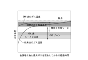
一般に、気相で粒子を生成させるには、原料ガスと還元ガスの混合ガスを高温の管に供給しガス温を上げて反応させる。このときガス中で粒子を発生させるには、図1に示す核粒子生成ゾーン(Homogeneous Nucleation zone)で原料ガスを反応させることが必要である。しかし、この核粒子生成ゾーンから該ゾーンよりも低温領域にかけて化学気相蒸着ゾーン(CVDゾーン)或いはHeterogeneous Growth zoneとも呼ばれる領域が存在しているため、原料ガスを加熱して粒子を生成させようとすると、加熱過程でCVDゾーンを通過することとなる。このゾーンで核となる粒子が少数存在していると、この核粒子の表面で原料ガスがCVD反応により分解し、固体が膜状に析出する。またこのCVDゾーンでは、温度が高いほど膜厚増加速度が大きく、CVDゾーンの上限温度範囲と核形成ゾーンの下限温度範囲とはオーバーラップしている。従って、加熱途中で温度が核形成ゾーンの下端域に到達すると少数の核粒子が生成し、同時に核粒子の周りでは高速でCVD反応による膜形成が起こり、粒子の径が急激に増大する。このようにして、原料ガスを加熱昇温するという手法では、大きな粒子しか製造できない。図1から理解されるように、従来公知の溶融析出法(VLD法)やシーメンス法によるシリコンの製造法での温度領域は、CVDゾーンの領域内にある。
尚、金属塩化物のガスと還元ガスとの加熱は、接触混合時に上記理想の粒子形成温度域となればよく、一方のガスの加熱温度が低くても、他方のガスが十分加熱されていればよいが、両ガスを上記温度域となる温度に加熱する態様が最も好ましい。
本発明の製造方法における金属とは、遷移金属だけでなく、Si、Ge等の半金属、卑金属、アルカリ金属、アルカリ土類金属も含む。上述した核粒子生成ゾーンと粒子成長ゾーンとの関係は、ほとんどの金属にあてはまるものであるため、目的物の金属種は特に制限されないが、ガス化が可能であり且つ還元ガスによる還元反応が速やかに行われるという観点から、シリコン(Si)、コバルト(Co)、ニッケル(Ni)、銅(Cu)及び(Fe)を例示することができる。特に、これらの金属種は、前述した核粒子生成ゾーンがほぼ同じ領域にあり、本発明の製造方法を実施するには、極めて好適である。
また、本発明により得られる金属粉末が、大きな比表面積を有すると同時に製造時点での酸素含量が少なく、且つ酸化され難く、従来法では全く得られていなかった物性を有しており且つ極めて有用であるという観点から、空気中に置けば常温でも容易に酸化してしまうシリコンの粉末の製造に、本発明は最も好適に適用される。
尚、自己分解とは、還元ガスと混合する前での加熱により熱分解して金属が生成してしまうことを意味する。
例えば、シリコン粉末を製造する場合;ジクロロシラン、トリクロロシラン及び四塩化ケイ素、特にトリクロロシラン及び四塩化ケイ素が挙げられる。
尚、ジクロロシランは、分解温度が低く、粒子同士が衝突して大粒子になり易いので、不可能ではないが、できれば原料としては避けることが望ましい。
その他の金属粉末を製造する場合;塩化コバルト(CoCl2)、塩化ニッケル(NiCl2)、塩化銅(CuCl2)、塩化鉄(FeCl3)をガス化して使用することも出来る。
還元ガスとしては、その機能を有するものであれば特に制限されず、水素の他、亜鉛を代表とする金属蒸気も使用可能であるが、気化しても完全に分子状に分散することが難しく、結果として瞬時に大量の核を発生させ、大きな表面積の金属粒子を作ることには適していない。また金属塩化物からの塩素引き抜きの際に発生する、塩化亜鉛などの副生金属塩化物の再利用にもコストがかかる。一方常に分子単位で分散していること、循環利用する場合に精製が容易であること、取扱いの容易さ、副生塩化物の再利用のし易さなどの観点から、SNN法の還元ガスには水素が最も好適に使用される。
因みに、トリクロロシランガスを用いた場合の還元反応は、下記式で表される。
SiHCl3+H2→ SiCl2+HCl+H2→ Si+3HCl
従って、この場合、トリクロロシラン1モル当りの水素ガスの量がほぼ1モル、好ましくは、それ以上となるような流量で水素ガスを供給すればよいこととなる。
本発明において、上記の金属塩化物ガス及び還元ガスは、接触混合することなく、それぞれ別個に加熱されて反応器内に供給され、反応器内で接触混合されて反応器から排出される。
本発明では、上記のようにして金属塩化物ガスと還元ガスとを接触混合し、生成した微細金属粒子を捕集することにより、目的とする高比表面積の金属粉末が得られる。
図2には、還元ガスとして水素ガスを用いた場合を例にとって、本発明方法が実施される製造ラインの一例を示した。
また、多重管3は、その中を流通するガスを加熱するための、伝熱、誘導加熱、誘電加熱、赤外線加熱などの加熱装置5を備え、多重管を通して供給される金属塩化物ガス及び還元ガスが所定の温度に加熱されて供給されるようになっている。
多重管を使用する場合、一つの加熱源で流通する各ガスの温度を正確にコントロールすることは難しい。そのためそれぞれの管に独立したヒーターを設け、別個にガスの温度を制御することも可能である。その方法として、ノズルを同心円上ではなく、隣り合って配置する方法、あるいはY字型に配置して、その合流点で反応させる方法等を採用できる。
第一の目的は上記熱融着を防止し、高い表面積を維持することである。ある程度の熱融着は、粒子の嵩密度を上げるために必要ではあるが、あまりに融着が進むと比表面積が下がり、超微粒子本来の特性が下がるため好ましくない。したがって素早く、例えばシリコン粒子の場合では1300℃以下の温度に0.1秒以内に下げることが好ましい。
また第二の目的として、副生塩化物、特に還元ガスに水素を使用した場合に発生する塩化水素との2次反応によるエッチングを防止することがあげられる。金属粒子が塩化水素によりエッチングされる温度は様々であり、触媒作用を持つ不純物によっても大きく異なるが、特に99%以上の高純度シリコンの場合、900℃以上では気相中でエッチングされる。このエッチングよる粒子の消耗を避けるため、比表面積が5~250m2/gのシリコン粉末を得るためには、1秒以内に、出来れば0.5秒以内にエッチング反応がほとんど起きない800℃まで生成した粒子を冷却するのが望ましい。そのためには、反応器1の下部に、水冷管や伝熱ブロック等の冷却手段を設けたり(図示せず)、回収可能な不活性の冷却材、例えば、反応排ガスを冷却してコンデンスさせた液や、液状四塩化珪素等をシャワーリングし、金属粉末を含む反応後のガスを冷却することが好ましい。
即ち、捕集器7を通過した排ガスは、コンプレッサー13により循環されるが、この排ガスには、水素ガスに加え、捕集されなかった金属微粒子、未反応の金属塩化物、副生金属塩化物および還元により生成した塩化水素を含んでおり、これらの混合ガスに含まれる水素以外の成分は、低圧深冷機11吸収塔、及び高圧深冷器15により殆どが取り除かれ、最終的に吸着塔17で水素を主成分とするガスと塩化水素や他のガスとに分離精製された後、循環供給される構造となっている。
尚、図2に示されているように、消費した水素を補うような流量で水素ガスが循環ライン9に補給される。
尚、上述したプロセスにおいて、低圧深冷及び高圧深冷で分離した凝縮液を蒸留塔18で処理し、気化した金属塩化物を再度反応に供することが出来る。SNN法は一瞬で反応が完了するため、粒子の成長はほとんど考慮する必要がないため、上記金属化合物中に金属粒子が残存していても、これをそのまま反応器に再フィードした場合、得られる製品に大きな違いは認められない。また同様の理由から、水素中に含まれる未回収の金属微粒子も、得られる製品には大きな影響を与えない。
本発明者らの確認によれば、前述のように本発明の方法によって得られた金属粉末は、その製造方法に起因して、粒子表面の20%以上が塩素で終端されており、塩素原子の大きさから考えて、非常に酸化が起こりにくい構造であると推定される。
いずれにしても、本発明のSNN法で製造した金属粒子は、空気中に暴露された場合でも、従来の製造方法で得られた金属粉末と異なり、発熱が極めて少なく、大量に金属粉末を扱う場合の安全性に関しては、工業的に極めて有利であり、例えば、総表面積(比表面積×重量)が1000m2以上の単位量においても安全に取り扱うことが可能である。
特に、本発明方法で得られるシリコン粉末は、BET比表面積が前述した範囲にあると共に、常温(25℃)、常圧(大気圧)及び湿度が50%の空気中に24時間放置したときに測定される見かけの酸化膜の厚みが5nmであることが確認されている。
しかるに、上記の方法で得られるシリコン粉末は、大きなBET比表面積を有しているためリチウムイオンを吸蔵しても割れにくく、しかも、酸素含量が著しく低減されているため、酸素がリチウムイオンと反応してしまうという不都合も有効に解消できる。更に表面が酸化しにくい構造であるため、総表面積(比表面積×重量)が1000m2以上の工業的な量で取り扱っても、酸化による発熱を起こさないため全く問題を起こさない。
従って、かかるシリコン粉末は、リチウムイオン二次電池の負極材として極めて好適であり、実用化において黒鉛と混合して使用する場合においても、例えば黒鉛100質量部当り10質量部以上、特に20質量部以上もの多量で黒鉛に配合してリチウムイオン二次電池の負極を形成することができる。
金属粒子の直径d(m)=6/ρS
式中、Sは、粒子のBET比表面積(m2/kg)であり、
ρは、金属粒子の密度(kg/m3)である。

Coxは酸化膜の重量分率であり、元素分析により測定された酸素濃度から求めた。
dは見かけの平均粒子径(m)で、比表面積(m2/kg)から求めた。
ρoxは酸化膜の密度(kg/m3)である。
ρmは金属粒子の密度(kg/m3)である。
尚、表1に示されているガス温度は、反応装置のモデルを作成し、グラファイトの温度測定結果からANSYSの推奨する電磁場解析、流体解析、および熱伝導解析の結果から推定した温度である。
トリクロロシラン0.1Nm3/hと、水素2Nm3/hを別個に加熱し、SNN法で1時間シリコン微粒子を作成し、約15gのシリコン粉末を得た。シリコンの収率は約15%であった。
各種ガスのガス温と共に、得られた粒子のBET比表面積、粒子径及び見かけの酸化膜厚を表1に示した。
また、得られたシリコン粒子の電子顕微鏡写真を図3に示した。図3から、単分散した均一な粒子径であったことが判る。
トリクロロシラン0.2Nm3/hと、水素2Nm3/hを別個に加熱し、SNN法で1時間シリコン微粒子を作成し、約50gのシリコン粉末を得た。シリコンの収率は約20%であった。
各種ガスのガス温と共に、得られた粒子のBET比表面積、粒子径及び見かけの酸化膜厚を表1に示した。
また、得られたシリコン粒子の電子顕微鏡写真を図4に示した。図4から、単分散した均一な粒子径であったことが判る。
トリクロロシラン0.5Nm3/hと、水素2.5Nm3/hを別個に加熱し、SNN法で1時間シリコン微粒子を作成し、約120gのシリコン粉末を得た。シリコンの収率は約20%であった。
各種ガスのガス温と共に、得られた粒子のBET比表面積、粒子径及び見かけの酸化膜厚を表1に示した。また、得られたシリコン粒子の電子顕微鏡写真を図5に示した。
得られたシリコン粒子は凝集していることが判る。
トリクロロシラン1.0Nm3/hと、水素2.5Nm3/hを別個に加熱し、SNN法で1時間シリコン微粒子を作成し、約250gのシリコン粉末を得た。シリコンの収率は約20%であった。得られた粒子は凝集していた。
各種ガスのガス温と共に、得られた粒子のBET比表面積、粒子径及び見かけの酸化膜厚を表1に示した。
トリクロロシラン0.5Nm3/hと、水素2.5Nm3/hを別個に加熱し、SNN法で1時間シリコン微粒子を作成したが、シリコン微粒子を捕集できず、収率は0%だった。ガス温度が低かったため、十分な核形成が行われなかったものと思われる。
トリクロロシラン0.5Nm3/hと水素2.5Nm3/hを流量測定した直後に混合し、同じノズルからフィードした。図6に示すシリコン粒子は得られたものの、比表面積が3m2/gと低く、融着した粒子が得られた。

3:多重管
5:加熱装置
7:捕集器
9:水素循環ライン
13:コンプレッサー
Claims (10)
- 金属塩化物ガスと還元ガスとを用意する準備工程;
前記金属塩化物ガスと還元ガスとを接触混合させての気相還元反応により、ガス流中に金属粒子を生成させる気相還元工程;
前記気相還元反応後のガス流から金属粒子を捕集して金属粉末を得る捕集工程;
を含む金属粉末の製造方法において、
前記準備工程において、前記金属塩化物ガスと還元ガスとは、それぞれ別個に加熱され、且つ前記金属塩化物ガスは、該金属塩化物の熱分解温度未満に保持しておき、
前記気相還元工程において、前記金属塩化物ガスと前記還元ガスとの接触により、該金属塩化物ガスと還元ガスとの混合ガスの温度を、前記気相還元反応が起こる温度以上に到達させ、
前記捕集工程で得られる金属粉末は、5~250m2/gのBET比表面積を有していることを特徴とする金属粉末の製造方法。 - 前記気相還元工程において、前記金属塩化物のガスと還元ガスとの接触後、反応後のガスが直ちに冷却される請求項1に記載の製造方法。
- 前記準備工程において、多重管を使用し、該多重管の少なくとも1つの管に金属塩化物ガスを供給すると共に、該多重管の少なくとも一つの他の管に還元ガスを供給することにより、該多重管内で前記金属塩化物ガスの加熱と前記還元ガスの加熱とが別個に行われる請求項1に記載の製造方法。
- 前記気相還元工程において、前記多重管のガス出口で、前記金属塩化物ガスと還元ガスとが合流しての接触により気相還元反応が行われる請求項3に記載の製造方法。
- 前記還元ガスが、水素ガスである、請求項1に記載の製造方法。
- 前記金属塩化物としてケイ素塩化物を使用し、前記金属粉末としてシリコン粉末を得る、請求項5に記載の製造方法。
- 前記ケイ素塩化物が、トリクロロシランまたは四塩化ケイ素である、請求項6に記載の製造方法。
- 前記反応後のガス流に含まれる金属粒子を捕集した後、該ガス流から水素ガスを分離し、分離された水素ガスを前記準備工程に供給する請求項5に記載の製造方法。
- 前記反応後のガス流から生成した金属粒子を捕集した後、該ガス流から水素ガスと金属粒子を含む金属塩化物とを分離し、次いで、分離された金属塩化物に含まれる金属粒子を回収した後、該金属塩化物を前記準備工程に供給する請求項5に記載の製造方法。
- BET比表面積が5~250m2/gの範囲にあり、且つ、常温、常圧、湿度50%の空気中で24時間放置後に測定される見かけの酸化膜の厚みが5nm未満であるシリコン粉末。
Priority Applications (5)
| Application Number | Priority Date | Filing Date | Title |
|---|---|---|---|
| US16/093,803 US10953469B2 (en) | 2016-04-21 | 2017-04-07 | Method of producing metal powder |
| CN201780023089.5A CN108883942A (zh) | 2016-04-21 | 2017-04-07 | 金属粉末的制造方法 |
| EP17785827.1A EP3447028A4 (en) | 2016-04-21 | 2017-04-07 | METHOD FOR PRODUCING METAL POWDER |
| JP2018513114A JPWO2017183487A1 (ja) | 2016-04-21 | 2017-04-07 | 金属粉末の製造方法 |
| KR1020187028265A KR20180136941A (ko) | 2016-04-21 | 2017-04-07 | 금속 분말의 제조 방법 |
Applications Claiming Priority (2)
| Application Number | Priority Date | Filing Date | Title |
|---|---|---|---|
| JP2016085172 | 2016-04-21 | ||
| JP2016-085172 | 2016-04-21 |
Publications (1)
| Publication Number | Publication Date |
|---|---|
| WO2017183487A1 true WO2017183487A1 (ja) | 2017-10-26 |
Family
ID=60115929
Family Applications (1)
| Application Number | Title | Priority Date | Filing Date |
|---|---|---|---|
| PCT/JP2017/014531 WO2017183487A1 (ja) | 2016-04-21 | 2017-04-07 | 金属粉末の製造方法 |
Country Status (7)
| Country | Link |
|---|---|
| US (1) | US10953469B2 (ja) |
| EP (1) | EP3447028A4 (ja) |
| JP (1) | JPWO2017183487A1 (ja) |
| KR (1) | KR20180136941A (ja) |
| CN (1) | CN108883942A (ja) |
| TW (1) | TWI717497B (ja) |
| WO (1) | WO2017183487A1 (ja) |
Families Citing this family (3)
| Publication number | Priority date | Publication date | Assignee | Title |
|---|---|---|---|---|
| WO2018082789A1 (de) | 2016-11-07 | 2018-05-11 | Wacker Chemie Ag | Verfahren zum mahlen von silizium enthaltenden feststoffen |
| US10612111B2 (en) * | 2018-08-21 | 2020-04-07 | Robert Ten | Method and apparatus for extracting high-purity gold from ore |
| CN109865832A (zh) * | 2019-04-02 | 2019-06-11 | 柳州光华科技有限公司 | 一种铜金属粉末的深加工方法 |
Citations (10)
| Publication number | Priority date | Publication date | Assignee | Title |
|---|---|---|---|---|
| JPS5533601B2 (ja) | 1975-08-30 | 1980-09-01 | ||
| JPS5618113B2 (ja) | 1975-10-27 | 1981-04-27 | ||
| JPH01239014A (ja) * | 1988-03-22 | 1989-09-25 | Nkk Corp | 多結晶シリコンの製造方法及び装置 |
| JP2002029726A (ja) * | 2000-05-11 | 2002-01-29 | Tokuyama Corp | シリコン生成用反応装置 |
| JP2003002628A (ja) * | 2001-06-21 | 2003-01-08 | Tokuyama Corp | シリコン製造装置および製造方法 |
| JP2003020217A (ja) * | 2001-07-03 | 2003-01-24 | Tokuyama Corp | シリコンおよびトリクロロシランの製造法 |
| JP2005503984A (ja) * | 2001-09-19 | 2005-02-10 | エバーグリーン ソーラー, インコーポレイテッド | 化学的に接近可能な表面を有するケイ素ナノクリスタルを調製するための高収率方法 |
| JP2007511460A (ja) * | 2003-11-19 | 2007-05-10 | デグサ ゲーエムベーハー | ナノスケールの結晶質シリコン粉末 |
| JP2007513041A (ja) * | 2003-11-19 | 2007-05-24 | デグサ ゲーエムベーハー | ナノスケールの結晶質シリコン粉末 |
| JP5258339B2 (ja) | 2008-03-24 | 2013-08-07 | 株式会社トクヤマ | シリコン製造プロセス |
Family Cites Families (18)
| Publication number | Priority date | Publication date | Assignee | Title |
|---|---|---|---|---|
| GB2028289B (en) * | 1978-08-18 | 1982-09-02 | Schumacher Co J C | Producing silicon |
| US5498446A (en) * | 1994-05-25 | 1996-03-12 | Washington University | Method and apparatus for producing high purity and unagglomerated submicron particles |
| JP2000345218A (ja) | 1999-05-31 | 2000-12-12 | Toho Titanium Co Ltd | 金属粉末製造用原料吐出ノズルおよび金属粉末の製造装置ならびに金属粉末の製造方法 |
| CA2377892C (en) | 2000-05-11 | 2009-02-03 | Tokuyama Corporation | Polycrystalline silicon, method and apparatus for producing the same |
| JP3584235B2 (ja) | 2000-12-04 | 2004-11-04 | 住友チタニウム株式会社 | トリクロロシランの精製方法 |
| WO2004020128A1 (ja) * | 2002-08-28 | 2004-03-11 | Toho Titanium Co., Ltd. | 金属ニッケル粉末及びその製造方法 |
| WO2004030853A1 (ja) | 2002-09-30 | 2004-04-15 | Toho Titanium Co., Ltd. | 金属粉末の製造方法および製造装置 |
| JP4294387B2 (ja) | 2003-06-16 | 2009-07-08 | 株式会社トクヤマ | シリコンの製造方法 |
| JP4540364B2 (ja) | 2004-03-01 | 2010-09-08 | 東邦チタニウム株式会社 | ニッケル粉末、並びにそれを用いた導電ペースト及び積層セラミックコンデンサ |
| DE102005042753A1 (de) * | 2005-09-08 | 2007-03-15 | Wacker Chemie Ag | Verfahren und Vorrichtung zur Herstellung von granulatförmigem polykristallinem Silicium in einem Wirbelschichtreaktor |
| JP5339948B2 (ja) | 2009-02-12 | 2013-11-13 | 株式会社大阪チタニウムテクノロジーズ | 高純度多結晶シリコン製造方法 |
| CN101717087B (zh) * | 2009-11-25 | 2011-08-10 | 江苏中能硅业科技发展有限公司 | 一种多晶硅棒的制造方法 |
| US10181600B2 (en) | 2010-06-29 | 2019-01-15 | Umicore | Submicron sized silicon powder with low oxygen content |
| CN103153855A (zh) * | 2010-10-22 | 2013-06-12 | Memc电子材料有限公司 | 在基本闭环的方法和系统中制备多晶硅 |
| JP5533601B2 (ja) | 2010-11-11 | 2014-06-25 | 有限会社シーエス技術研究所 | 高純度シリコン微粉末の製造装置 |
| JP5571537B2 (ja) * | 2010-11-22 | 2014-08-13 | 日立金属株式会社 | 金属チタン製造装置および金属チタンの製造方法 |
| JP6016729B2 (ja) | 2013-08-02 | 2016-10-26 | 東邦チタニウム株式会社 | 金属粉末の製造方法及び製造装置 |
| CN103449440B (zh) * | 2013-08-23 | 2015-04-01 | 中国恩菲工程技术有限公司 | 制备多晶硅的设备 |
-
2017
- 2017-04-07 JP JP2018513114A patent/JPWO2017183487A1/ja not_active Ceased
- 2017-04-07 WO PCT/JP2017/014531 patent/WO2017183487A1/ja active Application Filing
- 2017-04-07 EP EP17785827.1A patent/EP3447028A4/en not_active Withdrawn
- 2017-04-07 US US16/093,803 patent/US10953469B2/en active Active
- 2017-04-07 CN CN201780023089.5A patent/CN108883942A/zh not_active Withdrawn
- 2017-04-07 KR KR1020187028265A patent/KR20180136941A/ko active IP Right Grant
- 2017-04-17 TW TW106112707A patent/TWI717497B/zh not_active IP Right Cessation
Patent Citations (10)
| Publication number | Priority date | Publication date | Assignee | Title |
|---|---|---|---|---|
| JPS5533601B2 (ja) | 1975-08-30 | 1980-09-01 | ||
| JPS5618113B2 (ja) | 1975-10-27 | 1981-04-27 | ||
| JPH01239014A (ja) * | 1988-03-22 | 1989-09-25 | Nkk Corp | 多結晶シリコンの製造方法及び装置 |
| JP2002029726A (ja) * | 2000-05-11 | 2002-01-29 | Tokuyama Corp | シリコン生成用反応装置 |
| JP2003002628A (ja) * | 2001-06-21 | 2003-01-08 | Tokuyama Corp | シリコン製造装置および製造方法 |
| JP2003020217A (ja) * | 2001-07-03 | 2003-01-24 | Tokuyama Corp | シリコンおよびトリクロロシランの製造法 |
| JP2005503984A (ja) * | 2001-09-19 | 2005-02-10 | エバーグリーン ソーラー, インコーポレイテッド | 化学的に接近可能な表面を有するケイ素ナノクリスタルを調製するための高収率方法 |
| JP2007511460A (ja) * | 2003-11-19 | 2007-05-10 | デグサ ゲーエムベーハー | ナノスケールの結晶質シリコン粉末 |
| JP2007513041A (ja) * | 2003-11-19 | 2007-05-24 | デグサ ゲーエムベーハー | ナノスケールの結晶質シリコン粉末 |
| JP5258339B2 (ja) | 2008-03-24 | 2013-08-07 | 株式会社トクヤマ | シリコン製造プロセス |
Non-Patent Citations (1)
| Title |
|---|
| See also references of EP3447028A4 |
Also Published As
| Publication number | Publication date |
|---|---|
| CN108883942A (zh) | 2018-11-23 |
| US10953469B2 (en) | 2021-03-23 |
| KR20180136941A (ko) | 2018-12-26 |
| JPWO2017183487A1 (ja) | 2019-03-07 |
| EP3447028A4 (en) | 2019-11-06 |
| TW201806858A (zh) | 2018-03-01 |
| TWI717497B (zh) | 2021-02-01 |
| EP3447028A1 (en) | 2019-02-27 |
| US20190076931A1 (en) | 2019-03-14 |
Similar Documents
| Publication | Publication Date | Title |
|---|---|---|
| WO2017183487A1 (ja) | 金属粉末の製造方法 | |
| JPH11502760A (ja) | 高速冷却反応器及び方法 | |
| JPS60500370A (ja) | 弗化珪素酸から珪素を得る方法および装置 | |
| US20220274837A1 (en) | Refining Process for Producing Solar Silicon, Silicon Carbide, High-Purity Graphite, and Hollow Silica Microspheres | |
| EP1018386B1 (en) | Method for producing nickel powder | |
| WO2010022601A1 (zh) | 高纯度硅的制造方法 | |
| JP2004002138A (ja) | シリコンの製造方法 | |
| CN110540208A (zh) | 一种生产硅的方法 | |
| TW201329280A (zh) | 在實質上封閉迴路方法及系統中之多晶矽的製造 | |
| WO2004030853A1 (ja) | 金属粉末の製造方法および製造装置 | |
| TWI716962B (zh) | 六氟化鎢的製造方法 | |
| Ouyang et al. | Study on thermodynamic equilibrium and character inheritance of cobalt carbonate decomposition | |
| EP3565782A1 (en) | Refining process for producing solar silicon, silicon carbide, high-purity graphite and hollow silica microspheres | |
| CN106167259B (zh) | 沉淀金属离子的碳纳米管纯化系统 | |
| JP5586005B2 (ja) | シリコンの製造方法 | |
| KR20170108881A (ko) | 폴리실리콘 제조를 위한 초고온 석출 공정 | |
| RU2777468C1 (ru) | Способ получения нанокристаллического порошка кремния | |
| CN210656179U (zh) | 一种宏量制备硅纳米材料装置 | |
| JP2009292675A (ja) | シリコン又はハロゲン化シランの製造方法及び製造装置 | |
| JPS6256506A (ja) | 金属タンタル粉末の製造方法 | |
| KR101388904B1 (ko) | 금속 산화물 입자의 제조 방법 및 제조 장치 | |
| JP2702954B2 (ja) | 高純度タンタル又は高純度ニオブ微粒子の製造方法 | |
| CN116143083A (zh) | 一种氮化硼纳米管的浮动催化式制备方法 | |
| TW202043147A (zh) | 矽微粒子的製造方法 | |
| RU2448809C2 (ru) | Способ получения порошка вольфрама |
Legal Events
| Date | Code | Title | Description |
|---|---|---|---|
| ENP | Entry into the national phase |
Ref document number: 20187028265 Country of ref document: KR Kind code of ref document: A |
|
| ENP | Entry into the national phase |
Ref document number: 2018513114 Country of ref document: JP Kind code of ref document: A |
|
| NENP | Non-entry into the national phase |
Ref country code: DE |
|
| WWE | Wipo information: entry into national phase |
Ref document number: 2017785827 Country of ref document: EP |
|
| ENP | Entry into the national phase |
Ref document number: 2017785827 Country of ref document: EP Effective date: 20181121 |
|
| 121 | Ep: the epo has been informed by wipo that ep was designated in this application |
Ref document number: 17785827 Country of ref document: EP Kind code of ref document: A1 |