WO2017158682A1 - 基板処理装置、コントローラ及び記録媒体 - Google Patents
基板処理装置、コントローラ及び記録媒体 Download PDFInfo
- Publication number
- WO2017158682A1 WO2017158682A1 PCT/JP2016/057973 JP2016057973W WO2017158682A1 WO 2017158682 A1 WO2017158682 A1 WO 2017158682A1 JP 2016057973 W JP2016057973 W JP 2016057973W WO 2017158682 A1 WO2017158682 A1 WO 2017158682A1
- Authority
- WO
- WIPO (PCT)
- Prior art keywords
- data
- maintenance
- component
- unit
- display
- Prior art date
- Legal status (The legal status is an assumption and is not a legal conclusion. Google has not performed a legal analysis and makes no representation as to the accuracy of the status listed.)
- Ceased
Links
Images










Classifications
-
- G—PHYSICS
- G07—CHECKING-DEVICES
- G07C—TIME OR ATTENDANCE REGISTERS; REGISTERING OR INDICATING THE WORKING OF MACHINES; GENERATING RANDOM NUMBERS; VOTING OR LOTTERY APPARATUS; ARRANGEMENTS, SYSTEMS OR APPARATUS FOR CHECKING NOT PROVIDED FOR ELSEWHERE
- G07C3/00—Registering or indicating the condition or the working of machines or other apparatus, other than vehicles
- G07C3/005—Registering or indicating the condition or the working of machines or other apparatus, other than vehicles during manufacturing process
-
- G—PHYSICS
- G06—COMPUTING OR CALCULATING; COUNTING
- G06Q—INFORMATION AND COMMUNICATION TECHNOLOGY [ICT] SPECIALLY ADAPTED FOR ADMINISTRATIVE, COMMERCIAL, FINANCIAL, MANAGERIAL OR SUPERVISORY PURPOSES; SYSTEMS OR METHODS SPECIALLY ADAPTED FOR ADMINISTRATIVE, COMMERCIAL, FINANCIAL, MANAGERIAL OR SUPERVISORY PURPOSES, NOT OTHERWISE PROVIDED FOR
- G06Q10/00—Administration; Management
- G06Q10/20—Administration of product repair or maintenance
-
- G—PHYSICS
- G05—CONTROLLING; REGULATING
- G05B—CONTROL OR REGULATING SYSTEMS IN GENERAL; FUNCTIONAL ELEMENTS OF SUCH SYSTEMS; MONITORING OR TESTING ARRANGEMENTS FOR SUCH SYSTEMS OR ELEMENTS
- G05B19/00—Program-control systems
- G05B19/02—Program-control systems electric
- G05B19/18—Numerical control [NC], i.e. automatically operating machines, in particular machine tools, e.g. in a manufacturing environment, so as to execute positioning, movement or co-ordinated operations by means of program data in numerical form
- G05B19/406—Numerical control [NC], i.e. automatically operating machines, in particular machine tools, e.g. in a manufacturing environment, so as to execute positioning, movement or co-ordinated operations by means of program data in numerical form characterised by monitoring or safety
- G05B19/4065—Monitoring tool breakage, life or condition
-
- G—PHYSICS
- G05—CONTROLLING; REGULATING
- G05B—CONTROL OR REGULATING SYSTEMS IN GENERAL; FUNCTIONAL ELEMENTS OF SUCH SYSTEMS; MONITORING OR TESTING ARRANGEMENTS FOR SUCH SYSTEMS OR ELEMENTS
- G05B19/00—Program-control systems
- G05B19/02—Program-control systems electric
- G05B19/18—Numerical control [NC], i.e. automatically operating machines, in particular machine tools, e.g. in a manufacturing environment, so as to execute positioning, movement or co-ordinated operations by means of program data in numerical form
- G05B19/409—Numerical control [NC], i.e. automatically operating machines, in particular machine tools, e.g. in a manufacturing environment, so as to execute positioning, movement or co-ordinated operations by means of program data in numerical form characterised by using manual data input [MDI] or by using control panel, e.g. controlling functions with the panel; characterised by control panel details or by setting parameters
-
- G—PHYSICS
- G05—CONTROLLING; REGULATING
- G05B—CONTROL OR REGULATING SYSTEMS IN GENERAL; FUNCTIONAL ELEMENTS OF SUCH SYSTEMS; MONITORING OR TESTING ARRANGEMENTS FOR SUCH SYSTEMS OR ELEMENTS
- G05B23/00—Testing or monitoring of control systems or parts thereof
- G05B23/02—Electric testing or monitoring
- G05B23/0205—Electric testing or monitoring by means of a monitoring system capable of detecting and responding to faults
- G05B23/0259—Electric testing or monitoring by means of a monitoring system capable of detecting and responding to faults characterized by the response to fault detection
- G05B23/0283—Predictive maintenance, e.g. involving the monitoring of a system and, based on the monitoring results, taking decisions on the maintenance schedule of the monitored system; Estimating remaining useful life [RUL]
-
- G—PHYSICS
- G07—CHECKING-DEVICES
- G07C—TIME OR ATTENDANCE REGISTERS; REGISTERING OR INDICATING THE WORKING OF MACHINES; GENERATING RANDOM NUMBERS; VOTING OR LOTTERY APPARATUS; ARRANGEMENTS, SYSTEMS OR APPARATUS FOR CHECKING NOT PROVIDED FOR ELSEWHERE
- G07C3/00—Registering or indicating the condition or the working of machines or other apparatus, other than vehicles
- G07C3/02—Registering or indicating working or idle time only
- G07C3/06—Registering or indicating working or idle time only in graphical form
-
- H—ELECTRICITY
- H10—SEMICONDUCTOR DEVICES; ELECTRIC SOLID-STATE DEVICES NOT OTHERWISE PROVIDED FOR
- H10P—GENERIC PROCESSES OR APPARATUS FOR THE MANUFACTURE OR TREATMENT OF DEVICES COVERED BY CLASS H10
- H10P72/00—Handling or holding of wafers, substrates or devices during manufacture or treatment thereof
- H10P72/04—Apparatus for manufacture or treatment
- H10P72/0451—Apparatus for manufacturing or treating in a plurality of work-stations
- H10P72/0452—Apparatus for manufacturing or treating in a plurality of work-stations characterised by the layout of the process chambers
- H10P72/0458—Apparatus for manufacturing or treating in a plurality of work-stations characterised by the layout of the process chambers vertical arrangement
-
- H—ELECTRICITY
- H10—SEMICONDUCTOR DEVICES; ELECTRIC SOLID-STATE DEVICES NOT OTHERWISE PROVIDED FOR
- H10P—GENERIC PROCESSES OR APPARATUS FOR THE MANUFACTURE OR TREATMENT OF DEVICES COVERED BY CLASS H10
- H10P72/00—Handling or holding of wafers, substrates or devices during manufacture or treatment thereof
- H10P72/06—Apparatus for monitoring, sorting, marking, testing or measuring
- H10P72/0604—Process monitoring, e.g. flow or thickness monitoring
-
- H—ELECTRICITY
- H10—SEMICONDUCTOR DEVICES; ELECTRIC SOLID-STATE DEVICES NOT OTHERWISE PROVIDED FOR
- H10P—GENERIC PROCESSES OR APPARATUS FOR THE MANUFACTURE OR TREATMENT OF DEVICES COVERED BY CLASS H10
- H10P72/00—Handling or holding of wafers, substrates or devices during manufacture or treatment thereof
- H10P72/06—Apparatus for monitoring, sorting, marking, testing or measuring
- H10P72/0612—Production flow monitoring, e.g. for increasing throughput
-
- H—ELECTRICITY
- H10—SEMICONDUCTOR DEVICES; ELECTRIC SOLID-STATE DEVICES NOT OTHERWISE PROVIDED FOR
- H10P—GENERIC PROCESSES OR APPARATUS FOR THE MANUFACTURE OR TREATMENT OF DEVICES COVERED BY CLASS H10
- H10P72/00—Handling or holding of wafers, substrates or devices during manufacture or treatment thereof
- H10P72/06—Apparatus for monitoring, sorting, marking, testing or measuring
- H10P72/0616—Monitoring of warpages, curvatures, damages, defects or the like
-
- G—PHYSICS
- G05—CONTROLLING; REGULATING
- G05B—CONTROL OR REGULATING SYSTEMS IN GENERAL; FUNCTIONAL ELEMENTS OF SUCH SYSTEMS; MONITORING OR TESTING ARRANGEMENTS FOR SUCH SYSTEMS OR ELEMENTS
- G05B2219/00—Program-control systems
- G05B2219/30—Nc systems
- G05B2219/32—Operator till task planning
- G05B2219/32234—Maintenance planning
-
- G—PHYSICS
- G05—CONTROLLING; REGULATING
- G05B—CONTROL OR REGULATING SYSTEMS IN GENERAL; FUNCTIONAL ELEMENTS OF SUCH SYSTEMS; MONITORING OR TESTING ARRANGEMENTS FOR SUCH SYSTEMS OR ELEMENTS
- G05B2219/00—Program-control systems
- G05B2219/30—Nc systems
- G05B2219/45—Nc applications
- G05B2219/45031—Manufacturing semiconductor wafers
-
- G—PHYSICS
- G05—CONTROLLING; REGULATING
- G05B—CONTROL OR REGULATING SYSTEMS IN GENERAL; FUNCTIONAL ELEMENTS OF SUCH SYSTEMS; MONITORING OR TESTING ARRANGEMENTS FOR SUCH SYSTEMS OR ELEMENTS
- G05B2219/00—Program-control systems
- G05B2219/30—Nc systems
- G05B2219/45—Nc applications
- G05B2219/45045—Maintenance, automatic storage and retrieval system
Definitions
- This relates to maintenance part management of a semiconductor manufacturing apparatus which is a kind of substrate processing apparatus for processing a substrate.
- the part life, the maintenance (maintenance) cycle, etc. are determined for each part.
- a device manufacturer customer using a semiconductor manufacturing apparatus
- cleans a part managed by a cumulative film thickness such as a quartz part and replaces the part as necessary.
- maintenance management is performed based on the use time, the number of uses, and the accumulated film thickness.
- a threshold value for notifying the warning of data specifying wear such as the number of times of use is set by the user in advance and notified when the threshold value is exceeded.
- a warning is issued and replacement is performed, or a warning is not issued and replacement is performed after a failure. Therefore, the user who sets the threshold needs to set values in consideration of the part replacement period, the part lead time, and the number of times of use in advance. In addition, an erroneous operation due to an incorrect setting is also induced.
- An object of the present invention is to provide a configuration capable of grasping the usage status of components constituting a substrate processing apparatus.
- the display unit displays a maintenance part management screen that displays the part or the mechanism selected as a management object from each part or each mechanism that constitutes the apparatus as a management target.
- a screen control unit to be displayed, a collection unit that collects component data related to the maintenance component, a cumulative value of the component data and a preset threshold value are compared, and if the threshold value is exceeded, the replacement time and
- the determination unit, the calculation unit for calculating the replacement time, the screen control unit, the collection unit, the determination unit, and the calculation unit are respectively controlled to control the mechanism and the components constituting the mechanism.
- For the data calculate the replacement time based on the average value of the part data for each predetermined cycle and the cumulative value of the part data, and in order from the maintenance part including the most recent replacement time Configuration and an operation unit which is configured to be displayed on the display unit while updating the maintenance component displayed on the maintenance component management screen so as to align the is provided.
- the present invention it is possible to grasp the maintenance time of parts constituting the substrate processing apparatus and provide stable operation of the substrate processing apparatus.
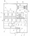
- FIG. 1 It is a perspective view which shows the substrate processing apparatus used suitably for one Embodiment of this invention. It is a sectional side view which shows the substrate processing apparatus used suitably for one Embodiment of this invention. It is sectional drawing which shows the controller structure used suitably for one Embodiment of this invention. It is a figure which shows the structure of the main controller (operation part) used suitably for one Embodiment of this invention. It is a figure for showing the structure of the components management program used suitably for the substrate processing apparatus of this invention. It is an example of illustration explaining the parts management program concerning one embodiment of the present invention. It is a figure explaining the processing flow of the component management function used suitably for the board
- the substrate processing apparatus 1 includes a housing 2, and a front maintenance port 4 serving as an opening provided for maintenance can be opened at a lower portion of the front wall 3 of the housing 2. Opened and closed by the maintenance door 5.
- a pod loading / unloading port 6 is opened on the front wall 3 of the housing 2 so as to communicate with the inside and outside of the housing 2, and the pod loading / unloading port 6 is a front shutter (loading / unloading opening / closing mechanism) 7.
- a load port (substrate transfer container delivery table) 8 is installed in front of the front side of the pod loading / unloading port 6, and the load port 8 is configured to align the placed pod 9. Has been.
- the pod 9 is a hermetically sealed substrate transfer container, and is loaded into the load port 8 by an in-process transfer device (not shown) and unloaded from the load port 8.
- a rotary pod shelf (substrate transfer container storage shelf) 11 is installed at an upper portion of the housing 2 at a substantially central portion in the front-rear direction.
- the rotary pod shelf 11 includes a plurality of pods 9. It is configured to store.
- the rotary pod shelf 11 is a vertically-supported support column 12 that is intermittently rotated, and a plurality of shelf plates (substrate transfer container placement) that are radially supported by the support column 12 at the upper, middle, and lower positions.
- the shelf 13 is configured to store the pod 9 in a state where a plurality of the pods 9 are mounted.
- a pod opener (substrate transfer container lid opening / closing mechanism) 14 is provided below the rotary pod shelf 11.
- the pod opener 14 can mount the pod 9 and can open and close the lid of the pod 9. It has a configuration.
- a pod transfer mechanism (container transfer mechanism) 15 is installed between the load port 8 and the rotary pod shelf 11 and the pod opener 14, and the pod transfer mechanism 15 holds the pod 9.
- the pod 9 can be moved between the load port 8, the rotary pod shelf 11, and the pod opener 14.
- a sub-housing 16 is provided over the rear end of the lower portion of the housing 2 at a substantially central portion in the front-rear direction.
- a pair of wafer loading / unloading ports (substrate loading / unloading ports) 19 for loading / unloading wafers (substrates) 18 into / from the sub-casing 16 are arranged on the front wall 17 of the sub-casing 16 vertically and vertically.
- the pod openers 14 are provided to the upper and lower wafer loading / unloading ports 19, 19, respectively.
- the pod opener 14 includes a mounting table 21 on which the pod 9 is mounted and an opening / closing mechanism 22 that opens and closes the lid of the pod 9.
- the pod opener 14 is configured to open and close the wafer doorway of the pod 9 by opening and closing the lid of the pod 9 mounted on the mounting table 21 by the opening and closing mechanism 22.
- the sub casing 16 constitutes a transfer chamber 23 that is airtight from a space (pod transport space) in which the pod transport mechanism 15 and the rotary pod shelf 11 are disposed.
- a wafer transfer mechanism (substrate transfer mechanism) 24 as a transfer robot is installed in the front region of the transfer chamber 23, and the wafer transfer mechanism 24 has a required number of wafers 18 (illustrated). 5 wafers), and the wafer mounting plate 25 can be moved directly in the horizontal direction, rotated in the horizontal direction, and moved up and down.
- the wafer transfer mechanism 24 is configured to load and unload the wafer 18 with respect to a boat (substrate holder) 26.
- a standby unit 27 that accommodates and waits for the boat 26 is configured, and a vertical processing furnace 28 is provided above the standby unit 27.
- the processing furnace 28 has a processing chamber 29 formed therein, the lower end portion of the processing chamber 29 is a furnace port portion, and the furnace port portion is opened and closed by a furnace port shutter (furnace port opening / closing mechanism) 31. It has become.
- a boat elevator (substrate holder lifting mechanism) 32 for raising and lowering the boat 26 is installed between the right end of the casing 2 and the right end of the standby section 27 of the sub casing 16.
- a seal cap 34 serving as a lid is horizontally attached to an arm 33 connected to a lifting platform of the boat elevator 32.
- the seal cap 34 supports the boat 26 vertically, and the boat 26 is treated as described above.
- the furnace port portion can be hermetically closed while being charged in the chamber 29.
- the boat 26 is configured to hold a plurality of (for example, about 50 to 125) wafers 18 in a horizontal posture with the wafers 18 aligned in the center.
- a clean unit 35 is disposed at a position opposite to the boat elevator 32 side, and the clean unit 35 includes a supply fan and a dust filter so as to supply a clean atmosphere or clean air 36 which is an inert gas. ing. Between the wafer transfer mechanism 24 and the clean unit 35, a notch alignment device (not shown) is installed as a substrate alignment device for aligning the circumferential position of the wafer 18.
- the clean air 36 blown out from the clean unit 35 is circulated through a notch aligner (not shown), the wafer transfer mechanism 24, and the boat 26, and is then sucked in by a duct (not shown), 2 is exhausted to the outside, or is blown out into the transfer chamber 23 by the clean unit 35.
- the pod loading / unloading port 6 When the pod 9 is supplied to the load port 8, the pod loading / unloading port 6 is opened by the front shutter 7.
- the pod 9 on the load port 8 is loaded into the housing 2 through the pod loading / unloading port 6 by the pod transport mechanism 15 and placed on the specified shelf 13 of the rotary pod rack 11. Is done.
- the pod 9 is temporarily stored in the rotary pod shelf 11, and then is transported from the shelf plate 13 to one of the pod openers 14 by the pod transport mechanism 15 and transferred to the mounting table 21. Alternatively, it is transferred directly from the load port 8 to the mounting table 21.
- the wafer loading / unloading port 19 is closed by the opening / closing mechanism 22, and the clean air 36 is circulated and filled in the transfer chamber 23.
- the oxygen concentration is set to 20 ppm or less, which is much lower than the oxygen concentration inside the housing 2 (atmosphere). ing.
- the opening side end surface of the pod 9 placed on the mounting table 21 is pressed against the opening edge of the wafer loading / unloading port 19 in the front wall 17 of the sub casing 16 and the lid is opened and closed. It is removed by the mechanism 22 and the wafer entrance is opened.
- the wafer 18 is taken out from the pod 9 by the wafer transfer mechanism 24 and transferred to a notch aligning device (not shown). After aligning 18, the wafer transfer mechanism 24 loads the wafer 18 into the standby section 27 located behind the transfer chamber 23 and charges (charges) the boat 26.
- the wafer transfer mechanism 24 that has transferred the wafer 18 to the boat 26 returns to the pod 9 and loads the next wafer 18 into the boat 26.
- the other (lower or upper) pod opener 14 has the rotary pod shelf. 11 and another pod 9 is transferred and transferred by the pod transfer mechanism 15, and the opening operation of the pod 9 by the other pod opener 14 is simultaneously performed.
- the furnace port portion of the processing furnace 28 closed by the furnace port shutter 31 is opened by the furnace port shutter 31. Subsequently, the boat 26 is raised by the boat elevator 32 and loaded into the processing chamber 29.
- the furnace port After loading, the furnace port is hermetically closed by the seal cap 34.
- the processing chamber 29 has a purge process (pre-purge process) in which it is replaced with an inert gas.
- the process chamber 29 is evacuated by a gas evacuation mechanism (not shown) so as to have a desired pressure (degree of vacuum).
- the processing chamber 29 is heated to a predetermined temperature by a heater driving unit (not shown) so as to have a desired temperature distribution.
- a process gas controlled to a predetermined flow rate is supplied by a gas supply mechanism (not shown), and the process gas is in contact with the surface of the wafer 18 in the process of flowing through the process chamber 29. Predetermined processing is performed on the top. Further, the processed gas after the reaction is exhausted from the processing chamber 29 by the gas exhaust mechanism.
- an inert gas is supplied from an inert gas supply source (not shown) by the gas supply mechanism, the processing chamber 29 is replaced with an inert gas, and the processing chamber The pressure of 29 is returned to normal pressure (after purge process). Then, the boat 26 is lowered by the boat elevator 32 through the seal cap 34.
- the wafer 18 and the pod 9 are paid out to the outside of the casing 2 in the reverse order of the above description. Unprocessed wafers 18 are further loaded into the boat 26, and batch processing of the wafers 18 is repeated.
- the processing furnace 28, a pod transport mechanism 15 which is a mechanism for transporting at least a substrate, a transport mechanism including a wafer transfer mechanism 24, a boat elevator 32, etc., a gas supply mechanism for supplying a processing gas or the like to the processing furnace 28, the processing A gas exhaust mechanism for exhausting the inside of the furnace 28, a heater driving unit for heating the processing furnace 28 to a predetermined temperature, and the processing furnace 28, the transport mechanism, the gas supply mechanism, the gas exhaust mechanism, and the heater driving unit, respectively.
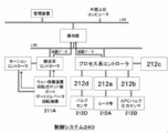
- the control system 240 to control is demonstrated with reference to FIG. 3, FIG.
- a main controller 201 a transport system controller 211 as a transport control unit, and a process system controller 212 as a processing control unit are provided. Since the main controller 201 is electrically connected to the transport system controller 211 and the process system controller 212 via a LAN (Local Area Network) such as 100BASE-T, for example, transmission / reception of each device data, downloading and uploading of each file, etc. Is possible.
- a management device may be included in the control system 240.
- the main controller 201 is provided with a port as a mounting portion into which a USB memory or the like as a recording medium as an external storage device is inserted or removed. An OS corresponding to this port is installed in the main controller 201.
- the main controller 201 is connected to an external host computer (not shown) via a communication network, for example. For this reason, even if the substrate processing apparatus 1 is installed in a clean room, the host computer can be placed in an office or the like outside the clean room.
- the management apparatus is connected to the substrate processing apparatus 1 via a LAN line and has a function of collecting apparatus data from the operation unit 201. Similarly, the management apparatus may be arranged in an office outside the clean room.
- the operation unit 201 has at least a function of collecting device data (hereinafter also referred to as component data) related to maintenance parts set in advance from the substrate data from the substrate processing apparatus 1 by executing a component management program. .
- the component data is data for monitoring maintenance information of each component constituting the substrate processing apparatus 1.
- the types of maintenance parts to be monitored are parts constituting the substrate processing apparatus 1 and each mechanism constituted by a plurality of parts.
- the apparatus data is not only data transmitted from each component constituting the substrate processing apparatus 1 to the operation unit 201, for example, control parameters such as temperature data, pressure data, and gas flow rate data, but also data indicating valve opening / closing.
- data generated by each controller for example, input data such as a set value input to the display unit 218 of the operation unit 201 is also included.
- the transfer system controller 211 mainly includes a rotary pod shelf 11, a boat elevator 32, a pod transfer mechanism (substrate container transfer mechanism) 15, a wafer transfer mechanism (substrate transfer mechanism) 24, a boat 26, and a rotation mechanism (not shown).
- the transfer system controller 211 includes a rotary pod rack 11, a boat elevator 32, a pod transfer mechanism (substrate container transfer mechanism) 15, a wafer transfer mechanism (substrate transfer mechanism) 24, and a rotation mechanism (not shown). It is comprised so that the conveyance operation of each mechanism including it may be controlled, respectively.
- the process system controller 212 includes a temperature controller 212a, a pressure controller 212b, a gas flow rate controller 212c, and a sequencer 212d.
- the temperature controller 212a, the pressure controller 212b, the gas flow rate controller 212c, and the sequencer 212d constitute a sub-controller and are electrically connected to the process system controller 212, so that each apparatus data is transmitted / received and each file is downloaded / uploaded. Etc. are possible.
- the process system controller 212 and the sub-controller are illustrated as separate bodies, but may be integrated.
- a heating mechanism 212A mainly composed of a heater, a temperature sensor, and the like is connected to the temperature controller 212a.
- the temperature controller 212 a is configured to adjust the temperature in the processing furnace 28 by controlling the temperature of the heater of the processing furnace 28.
- the temperature controller 212a is configured to perform switching (on / off) control of the thyristor and control power supplied to the heater wire.
- a gas exhaust mechanism 212B mainly composed of a pressure sensor, an APC valve as a pressure valve, and a vacuum pump is connected to the pressure controller 212b.
- the pressure controller 212b switches the opening of the APC valve and the vacuum pump (on / off) so that the pressure in the processing chamber 29 becomes a desired pressure at a desired timing based on the pressure value detected by the pressure sensor. Is configured to control.
- the gas flow rate controller 212c is configured by an MFC (Mass Flow Controller).
- the sequencer 212d is configured to control the supply and stop of gas from the processing gas supply pipe and the purge gas supply pipe by opening and closing the valve 212D. Further, the process system controller 212 controls the gas flow rate controller 212c (MFC) and the sequencer 212d (valve 212D) so that the flow rate of the gas supplied into the processing chamber 29 becomes a desired flow rate at a desired timing. It is configured.
- the main controller 201, the transport system controller 211, and the process system controller 212 according to the embodiment of the present invention can be realized using a normal computer system, not a dedicated system.
- each controller that executes a predetermined process is configured by installing the program from a recording medium (flexible disk, CD-ROM, USB, or the like) that stores the program for executing the above-described process in a general-purpose computer. can do.
- And means for supplying these programs is arbitrary.
- it may be supplied via a communication line, a communication network, a communication system, or the like.
- the program may be posted on a bulletin board of a communication network, and the program may be provided by being superimposed on a carrier wave via the network.
- a predetermined process can be executed by starting the program thus provided and executing it in the same manner as other application programs under the control of the OS.
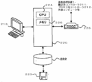
- the operation unit 201 includes a CPU (Central Processing Unit) 224 as a processing unit, a memory (RAM, ROM, etc.) 226 as a temporary storage unit, a hard disk (HDD) 222 as a storage unit, a transmission / reception module 228 as a communication unit, a display
- the display device 218 as a unit and a computer having a clock function (not shown) are configured.
- the hard disk 222 includes recipe files such as recipes in which processing conditions and processing procedures are defined, control program files for executing these recipe files, parameter files for setting processing conditions and processing procedures, and errors.
- various screen files including an input screen for inputting process parameters, various icon files, and the like (all not shown) are stored.
- a parts management program (FIG. 5 and the like) for managing maintenance parts of the semiconductor manufacturing apparatus is stored. Further, a maintenance parts list shown in FIG. 17 to be described later and a screen file of each screen shown in FIGS. 10 to 16 to be described later are stored.
- the display device 218 as a display unit is configured to display an operation screen for operating the substrate processing apparatus 1.
- the operation screen of the display device 218 includes a screen for confirming the state of the substrate transport system and the substrate processing system.
- an input unit for inputting operation instructions to the substrate transport system 211A and the substrate processing system (the heating mechanism 212A, the gas exhaust mechanism 212B, and the gas supply system 212C) shown in FIG. It is also possible to provide each operation button.
- the display device 218 displays information generated in the substrate processing apparatus 1 on the operation screen via the operation screen.
- the display device 218 outputs information displayed on the operation screen to a device such as a USB memory inserted in the operation unit 201.
- the display device 218 receives operator input data (input instruction) from the operation screen and transmits the input data to the operation unit 201.
- the display device 218 also instructs (controls) to execute an arbitrary substrate processing recipe (also referred to as a process recipe) out of a recipe developed in a memory (RAM) described later or a plurality of recipes stored in a storage unit described later. Instruction) is received and transmitted to the operation unit 201.
- the operation unit 201 executes a parts management program to function as a database that collects apparatus data, a function that extracts and accumulates part data related to maintenance parts from the apparatus data, and accumulated parts.
- a parts management program to function as a database that collects apparatus data, a function that extracts and accumulates part data related to maintenance parts from the apparatus data, and accumulated parts.
- processing each data to create trace data and graphing in time series, and expanding each stored screen table and reading device data to be described later A function for displaying each screen shown in FIGS. 10 to 16 on the display unit 218 is configured.
- the configuration of the parts management program will be described with reference to FIGS.
- the operation unit 201 includes a main control unit 220 including at least a CPU 224 and a memory 226, a communication unit 228 that transmits and receives data to and from an external computer via a network, and a storage unit 222 such as a hard disk drive.
- a configuration including a display unit such as a liquid crystal display and a user interface (UI) unit including a pointing device such as a keyboard and a mouse may be used.
- the control unit 220 may further include a communication unit 228.
- the main controller 201 transmits apparatus data such as the state of the substrate processing apparatus 1 to an external host computer, for example, a host computer, via a network (not shown).
- the substrate processing apparatus 1 is a vertical apparatus that performs, for example, oxidation, diffusion processing, and CVD processing on a substrate.
- the substrate processing apparatus 1 is controlled by the control system 240 based on each recipe file, each parameter file, and the like stored in the storage unit 222.
- the predetermined processing step is a substrate processing step which is one step of the semiconductor device manufacturing step is taken as an example.
- a substrate processing recipe (process recipe) corresponding to the substrate processing to be executed is developed in a memory such as a RAM in the process system controller 212, for example. Then, if necessary, an operation instruction is given from the main controller 201 to the process system controller 212 and the transport system controller 211.
- the substrate processing process performed in this manner includes at least a carry-in process, a film forming process, and a boat transfer process. Further, the transfer process (which may include a substrate loading process described later) may be included in the substrate processing process.
- the main controller 201 issues a drive instruction for the wafer transfer mechanism 24 to the transfer system controller 211. Then, while following the instruction from the transfer system controller 211, the wafer transfer mechanism 24 starts the transfer process of the wafer 18 from the pod 9 on the transfer stage 21 as a mounting table to the boat 26. This transfer process is performed until all the scheduled loading of wafers 18 into the boat 26 (wafer charge) is completed.
- the inside of the processing chamber 29 is evacuated by a vacuum evacuation device so as to have a predetermined film formation pressure (degree of vacuum) while following an instruction from the pressure controller 212b.
- the pressure in the processing chamber 29 is measured by a pressure sensor, and the pressure adjusting device is feedback-controlled based on the measured pressure information.
- the inside of the processing chamber 29 is heated by a heater so as to reach a predetermined temperature while following an instruction from the temperature control unit 212a.
- the current supply to the heater is feedback-controlled based on temperature information detected by a temperature sensor as a temperature detector so that the temperature in the processing chamber 29 becomes a predetermined temperature (film formation temperature).
- a predetermined gas processing gas
- predetermined processing for example, film formation
- the boat 26 holding the processed wafers 18 is extremely effectively cooled by the clean air 36 blown out from the clean unit 35. For example, when cooled to 150 ° C. or lower, the processed wafer 18 is removed from the boat 26 (wafer discharge) and transferred to the pod 9, and then a new unprocessed wafer 18 is transferred to the boat 26. Is done.
- the substrate processing apparatus 1 can, for example, form a silicon film on the wafer 18 with high throughput. .
- the maintenance parts in the present embodiment are collected in a list as shown in FIG. Parts listed in this list are targets for managing device data related to maintenance parts.
- This list is configured to include at least four items of item number, name, association, and display.
- FIG. 17 is merely an example, and items can be arbitrarily added or deleted.
- the item number column is the order in which a later-described component management program is read, and in principle, displayed in a list on the maintenance component management function main screen described later in this item number order.
- the part name column is the name of the maintenance part to be maintenance managed.
- the relation column is configured such that an item number is added when there is a relation between maintenance parts.
- the parts constituting the mechanism may be the target of the maintenance part. Therefore, this is an item provided to clarify related maintenance parts.
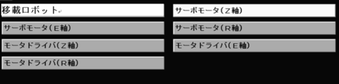
- information on four axes from No. 6 to No. 9 (X axis total drive pulse, Y axis total drive pulse, Z axis total drive pulse, R axis Total drive pulses).
- the display column is an item indicating whether or not to display on the maintenance part management function main screen. This is because there are many parts that should be managed as maintenance parts, and there are cases where parts to be managed may differ depending on the customer, so the maintenance parts management function is configured so that the maintenance parts displayed on the main screen can be selected. The operability is improved.
- FIG. 17 shows only nine maintenance parts, but this is only an example for explaining the present embodiment.
- the number of parts to be managed as a list as a maintenance target is not limited to nine. Hereinafter, it may be simply referred to as a parts list.
- a maintenance parts list for display to be displayed on the maintenance parts management function main screen may be provided. Even in this case, the maintenance parts list and the format (data structure) shown in FIG. 17 are the same.
- Component Management Program A component management program for providing the component management function in the present embodiment to the operation unit 201 of the substrate processing apparatus 1 will be described with reference to FIGS.
- the component management program creates a vertical type and a program that collects component data using the component management library (component management data control unit) in the memory 226 in the operation unit 201.
- the component management library component management data control unit
- the component management function in the present embodiment is used regardless of the apparatus form, the target film type, and the target process.
- the component management function in this embodiment is configured to have at least a component data collection function, a component data storage function, a trace graph display function, and a screen transition operation function.
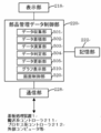
- the operation unit 201 is configured to realize a component management data control unit as shown in FIG. 6 by executing the component management program in the present embodiment.
- the component management data control unit includes a data collection unit 501, a data storage unit 502, a data calculation unit 503, a data determination unit 504, a data update unit 505, a graph display unit 510, and a screen control unit 520. , Is configured to include.
- the component management data control unit is connected to the display unit 218, the communication unit 228, and the storage unit 222, respectively, and is configured to be able to exchange data with each other.
- the data collection unit 501 is configured to collect device data (component data) related to the maintenance component among the device data transmitted via the communication unit 228.
- the data collection unit 501 is configured to extract component data from the device data and store it in the data storage unit 502.
- the data calculation unit 503 is configured to calculate a cumulative value of component data extracted from device data or an average value of component data in a predetermined cycle (for example, one day). In addition, the number of parts data is counted up. Then, the time (replacement time) exceeding the threshold value is calculated from the cumulative value of the part data and the average value of the part data.
- the threshold value is configured so as to be appropriately set by a component manufacturer recommended value or a component specification value.
- the data determination unit 504 is configured to compare the accumulated value of the component data with a preset threshold value and determine whether the accumulated value of the component data has reached the threshold value. An alarm may be generated when the accumulated value of the component data exceeds a threshold value. Further, when the maintenance part has a plurality of part data, the replacement timings of the respective calculated part data are compared, and the threshold value is determined based on the part data having the latest replacement time.
- the data update unit 505 is configured to update the component data in the data storage unit 502 according to the determination result of the data determination unit 504.
- the screen control unit 520 is configured to accept an operation instruction from the display unit 218 and perform screen transition processing.
- the screen control unit 520 is configured to display the result updated by the data update unit 505 or the result determined by the data determination unit 504 on the display unit 218.
- the graph display unit 510 is configured to acquire part data from the trace log file and display it in time series. According to the present embodiment, the trace graph shown in FIG. 13 is configured to be displayed.
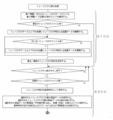
- FIGS. 7 to 9 are flowcharts for explaining the processing flow of the parts management function in the substrate processing apparatus 1 in this embodiment.
- the sequence for realizing the component data collection function shown in FIG. 7, the sequence for realizing the component data display function shown in FIG. 8, and the sequence for realizing the graph display function shown in FIG. 9 are executed at least.
- FIGS. 7 to 9 only show sequences in a state specialized for functions, and redundant description will be omitted.
- a screen transition program for performing screen switching display shown in FIG. 10 and later described later is configured to be executed.
- FIG. 7 shows an example of a sequence for realizing a component data collection function that is one of the component management functions, and this sequence is configured to be executed by a component management data control unit.
- the component management data control unit reads in advance a component data initial parameter file that defines component data to be collected from the storage unit 222 and develops it in the memory 226.
- a component data initial parameter file that defines component data to be collected from the storage unit 222 and develops it in the memory 226.
- an area of accumulated values and average values of all component data is secured in the data storage unit 502, and the latest trace log file is developed in that area and stored in the data storage unit.
- the component management data control unit confirms whether the device data is transmitted from the process system controller 212 or the transport system controller 211 as the control unit controller.
- the component management data control unit checks whether the device data included in the data message is device data related to the maintenance component, and extracts and extracts the device data as the component data.
- the stored component data is stored in the data storage unit 502. On the other hand, if the device data is not related to the maintenance component, the component management data control unit similarly confirms the relationship between the next device data and the maintenance component. In addition, when there is no device data, the component management data control unit confirms again whether or not a data message has been received from the control controller.
- the component management data control unit confirms reception of the data message from the control unit controller, and confirms whether the device data is component data related to the maintenance component. If the part management data control unit is part data, the part management data control unit compares it with the part data stored in the data storage unit 502, and the data calculation unit 503 integrates the data change amount according to the part data, or The component data cumulative value is calculated by counting up the number of times (or time).
- the component management data control unit causes the data determination unit 504 to compare the preset threshold value of the component data, and if the threshold value is exceeded, the component update data 505 reaches the threshold value of the component data cumulative value and the current time. The time is stored in the data storage unit 502 as the time. In this way, the next device data is extracted, and component data confirmation and component data comparison are performed in the same manner. When there is no more device data, it waits for reception of device data from the controller controller.
- the component management data control unit does not need to compare with the component data stored in the data storage unit 502, for example, when it is not necessary to calculate the component data accumulated value even for the component data, Even when there is no change, the data determination unit 504 performs comparison. If there is no need to compare the component data, the next device data extraction may be confirmed without comparing the data.
- the component data comparison function is configured to be automatically executed when the operation unit 201 is activated.
- FIG. 8 shows an example of a sequence for realizing a component data display function which is one of the component management functions, and this sequence is configured to be executed by the component management data control unit.
- the part management data control unit reads a part data initial parameter file defining part data to be collected in advance from the storage unit 222 and expands it in the memory 226. Specifically, the component management data control unit secures an area of accumulated values and average values of all component data in the data storage unit 502, expands the latest trace log file into the area, and stores it in the data storage unit 502. In addition, the data storage unit 502 is configured to secure an area for a maintenance part list for storing part data and a maintenance part list for display. Further, the parts management data control unit stores the current time in the area as a reference time and monitors the time. Note that the component data is updated at a predetermined cycle (for example, one day). In the present embodiment, description will be made on the assumption that the component data is updated every day.
- a predetermined cycle for example, one day. In the present embodiment, description will be made on the assumption that the component data is updated every day.
- the component management data control unit causes the data calculation unit 503 to calculate the average value of the component data when the reference time reaches the update time.
- the cumulative value and average value of all the display target component data and the current time are stored in the trace graph display area, and the cumulative value and average value of all the display target component data and the current time are stored as a trace log file. Save in the storage unit 502.
- the part management data control unit extracts part data for the maintenance parts in the maintenance parts list, updates the effective days up to the threshold value indicating the replacement time of the part data, and stores it as the effective day reference value. To do. Next, the part management data control unit extracts part data related to the maintenance part, and causes the data operation unit 503 to calculate the effective number of days until the threshold is reached as the replacement time based on the cumulative value and the average value of the part data. The data determination unit 504 compares the calculated effective days with the effective days reference value, and determines the shorter one by the replacement time. Then, the component management data control unit causes the data update unit 505 to update the valid days reference value as necessary.
- the component management data control unit causes the data determination unit 504 to compare the effective days (the number of days until the replacement time is reached) for all the component data related to the maintenance components in the maintenance component list, and the data update unit 505 most recently. Are registered in the parts maintenance list for display as the effective days reference value.
- the parts management data control unit repeats until all the maintenance parts in the maintenance parts list have been registered in the parts maintenance list for display as the valid days reference value in the data update unit 505 in the same manner.
- this flowchart shows a mechanism (for example, a pod transfer mechanism 15, a wafer transfer mechanism (substrate transfer mechanism) 24), a boat 26, and a rotation mechanism (not shown) in which the first maintenance part is composed of a plurality of parts.
- the lifetime can be calculated and managed for each component data.
- the parts management data control unit sends this validity to the data judgment unit 504.
- the date reference values are compared, and the data update unit 505 is configured to rearrange the maintenance parts from the display component list in ascending order of the effective day reference values.
- the component management data control unit is configured to control the screen control unit 520 that displays maintenance components in the order registered in the display component list.
- the parts data of the maintenance parts can be referred to, so that the maintenance parts that have reached the threshold value recommended for maintenance and replacement can be provided efficiently. Can do.
- FIG. 9 shows an example of a sequence for realizing a component data trace graph display function which is one of the component management functions, and this sequence is configured to be executed by the component management data control unit.
- the component management data control unit reads a component data initial parameter file that defines component data to be collected in advance from the storage unit 222 and expands it in the memory 226. Specifically, the component management data control unit secures an area of accumulated values and average values of all component data in the data storage unit 502, expands the latest trace log file into the area, and stores it in the data storage unit 502. At the same time, the data storage unit 502 secures areas for the maintenance part list for storing the part data and the maintenance part list for display. Further, the component management data control unit secures a trace log area for the first predetermined period (for example, for 7 days) and a display area for the second predetermined period (for example, for 12 days) in the data storage unit 502.
- the first predetermined period for example, for 7 days
- a display area for the second predetermined period for example, for 12 days
- the part management data control unit searches for the oldest trace log file in the first predetermined period, and when there is no oldest trace log file, the display preparation process ends. If the oldest trace log file exists, the trace log time and all device data are expanded at the beginning of the trace log data area.
- the parts management data control unit repeatedly searches up to the latest trace log file, expands the latest trace log file from the oldest trace log file, and stores the trace log time and all devices in the trace log data area in the data storage unit 502. Secure each data. In addition, the oldest and latest trace log time is stored in the data storage unit 502. Wait for instructions to display the trace graph.
- the part management data control unit checks whether or not the oldest trace graph (first trace graph) file exists. If there is no file, return to standby mode.
- the absence of the first trace log file means that the update process of the component data has not been executed once after the control system 240 (or the operation unit 201) is started, and what is displayed as a trace graph. Since it is not, it is configured to check in advance.
- the part management data control unit may be configured to control the screen control unit 520 so as to shift a button for displaying a trace log to a press-prohibited state while generating an alarm.
- the part management data control unit first stores the trace log time in the data storage unit 502 as a reference time. Then, the component management data control unit stores the selected trace graph target component data in the data storage unit 502 and causes the screen control unit 520 to display the name of the selected trace graph target component data. Further, the accumulated value and average value of the selected part data are taken out and stored in the top display area. In addition, the component management data control unit displays the date of the reference time on the screen control unit 520 and displays the points of accumulated values according to the scale.
- the part management data control unit adds one day to the reference time, checks whether the log time in the trace log file matches next, and if it does not match, the cumulative value and average value of the selected part data are the previous day's data.
- the date of the reference time is displayed on the graph display unit 510 while being stored in the display area for the accumulated cumulative date. This is because, for example, if the control system 240 is left off for 2 days and then turned on after 3 days, the data display process will be 3 days later, so the trace log of the date when the power was turned off Since it becomes a nonexistent state, it is possible to check it.
- the component management data control unit retrieves the accumulated value and average value of the selected component data from the trace log data when the reference time and the log time coincide with each other, saves it in the display area of the accumulated date, and displays the graph display unit
- the date of the reference time is displayed in 510, the point of the accumulated value is displayed in accordance with the scale, and a line connecting to the previously displayed point is displayed.
- the parts management data control unit is configured to repeatedly perform the same display processing on the graph display unit 510 until the reference time exceeds the latest log time.
- the component management data control unit causes the data calculation unit 503 to copy the accumulated value of the selected component data from the previous day's data, and to calculate the average value. Is copied from the previous day's data, and the expected value of the cumulative value is calculated from the average value.
- the average value for calculating the predicted value may be an average value of all average values up to the previous day.
- the graph is stored in the display area of the accumulated date, and the date of the reference time is displayed on the graph display unit 510, the point of the accumulated value is displayed in accordance with the scale, and a line connecting to the previously displayed point is displayed. It is configured as follows.
- the calculation method of the average value for calculating the predicted value of the cumulative value appropriately selects data for the first predetermined period (for example, 7 days) up to the previous day and causes the data calculation unit 503 to average the data. You may comprise.
- the component management data control unit is configured to repeatedly execute the predicted data display step until the reference time exceeds the second predetermined period (12 days).
- the part data of the maintenance part can be displayed in a graph on the time axis, the maintenance time can be predicted from the increasing tendency of the monitor value of the monitored part on the operation screen, Maintenance parts can be prepared in advance.
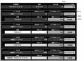
- FIG. 10 is an example of the display of the maintenance part list screen to be displayed.
- a maintenance component list is displayed as a maintenance component management function main screen as a maintenance component management screen.
- FIG. 10 is displayed when a predetermined activation button in the operation unit 201 is pressed. Mainly, a mechanism or a part selected as a maintenance part among the parts or a plurality of parts constituting the substrate processing apparatus 1 is displayed in a list.
- a maintenance part replacement time button hereinafter also referred to as a status display button
- the screen changes to a maintenance part management data detail screen shown in FIG. 12 to be described later, and the maintenance part replacement history is displayed.
- a button hereinafter also referred to as a component maintenance button
- the screen is changed to a maintenance component management replacement execution screen shown in FIG.
- the status of each maintenance component is configured to display the status display button 601 on the status display button 601 with the condition that the remaining number of days is the minimum for the set threshold among all the component data that affects the replacement timing.
- the screen control unit 520 displays the status display button 601 on the maintenance part management screen according to the most recent replacement time among the replacement times calculated for the mechanism and the component data of each of the components constituting the mechanism. It is configured to display by color.
- the screen control unit 520 displays “expiration date” when the part data replacement time exceeds the threshold, and when the part data replacement time is less than one year until the threshold, “Date” is displayed, and “Good” is displayed when the replacement time of the component data is one year or more until the threshold.
- the status display button 601 is configured to be displayed in yellow when the threshold value is less than 90 days, and further displayed in red when the threshold value is less than 30 days.
- the screen control unit 520 When the non-display item button 603 displayed on the maintenance part management screen is pressed, the screen control unit 520 is configured to display information on maintenance parts that are not displayed and are omitted from the maintenance part list. Further, this non-display button is also displayed in different colors in the same manner as the status display button 601 depending on the number of days until the replacement time of the parts data of maintenance parts that are not displayed as shown in FIG.
- the screen control unit 520 is configured to display a dialog box for determining whether to hide the maintenance part to be displayed.
- FIG. 11 shows a hidden item list screen that displays a list of maintenance parts that are not displayed.
- This screen is configured to return (display) the maintenance part management screen to the maintenance part management screen when the button of the maintenance part item to be returned to the display is pressed.
- the maintenance part item buttons displayed in FIG. 11 are displayed in different colors according to the number of days until the cumulative value of the part data reaches the threshold (replacement time), like the status display button on the maintenance part management screen. It is configured.
- the screen control unit 520 switches to a maintenance part management data detail screen that displays all part data that affects the replacement timing of the selected maintenance part. It is configured to
- the state of each condition is displayed according to the same rules as those on the main screen.
- a threshold display button 611 in this screen is pressed, a soft keyboard is displayed and the threshold can be changed.
- the data trace button 612 in this screen is pressed, the above-described trace graph is displayed for the corresponding component data described later.
- an exchange history button 613 in this screen is pressed, a change history detailed data screen described later is displayed.
- FIG. 12 is configured to be displayed by the screen control unit 520 when a vacuum robot is selected as a maintenance part in FIG. 10 and a status display button 601 corresponding to this vacuum robot is pressed.
- the upper items in FIG. 12 are items indicating states relating to the vacuum robot, and the use start date and time and the expiration date and time, the recommended lifetime (number of days) recommended by the component manufacturer, in this case, 300 days are set. It can be seen that the effective number of days until the expiration date and time indicating the replacement time is 291 days. It should be noted that numerical value data can be appropriately set by selecting the item 611 of the threshold value as the lifetime (number of days).
- FIG. 12 shows that four pieces of apparatus data are related to a vacuum robot as a maintenance part.
- such device data relating to maintenance parts is referred to as part data.
- the number of effective days until the expiration date is calculated, and the replacement time can be predicted.
- the current value that is the cumulative value of the component data up to now is 50
- the average value in a predetermined cycle for example, one day
- the threshold recommended by the component manufacturer is 1000.
- the current value 50 and the average value 5.5 in the present embodiment are calculated until the threshold value 1000 is reached by the average value 5.5
- the effective number of days is 191 as it is. Therefore, it is shown that the expiration date indicating the replacement time is September 4, 2016, the 191st day from the current time.
- the effective number of days is 46 days, so that the expiration date is April 12, 2016, the 46th day from the current time. Further, since the valid days are less than 90 days, the items of the expiration date and the valid days are displayed in different colors.
- the threshold value (pulse) item 611 numerical data can be set as appropriate.
- the replacement time when the current value reaches the numerical value set by the threshold value is displayed in time.
- the replacement time has been determined by the manufacturer's recommended value (300 days) of the transfer robot.
- the true replacement time of the transfer robot can be predicted by setting the threshold value for each component constituting the transfer robot and determining the replacement time of each component. Further, a history until the replacement time is reached can be displayed by a trace graph described below.
- FIG. 13A is configured such that the name of the component data in FIG. 12 is switched and displayed on the display unit 218 by the screen control unit 520 when the data trace button related to the X-axis total drive pulse is pressed.
- FIG. 13B is configured such that the name of the component data in FIG. 12 is switched and displayed on the display unit 218 by the screen control unit 520 when the data trace button regarding the R-axis drive pulse is pressed.
- a cell indicating a threshold 70
- a start cell indicating a trace start date 2016/2/20
- an end cell indicating a trace end date 2016/2/26
- the threshold reaching cell indicating the threshold reaching time is displayed. Since the X-axis total drive pulse has not reached the threshold value, the threshold value reaching cell is blank. Since the vertical axis is the number of pulses and the threshold is 70 pulses, the dotted line of 70 pulses is highlighted on the trace graph.
- the process of S300 in FIG. For example, the average of the average values of each predetermined period (1 day) from the trace start date (2016/2/20) to the trace end date (2016/2/26) is the trace end date (2016/2/26). By adding to the accumulated value, the accumulated value of the next day (2016/2/27) of the trace end date is calculated. Similarly, the cumulative value is calculated repeatedly until 2016/3/03 after the second predetermined period (for example, 12 days).
- the threshold arrival date of the X-axis total drive pulse is 2016/2/29 days. In this way, it is possible to estimate the replacement time particularly for maintenance parts that have not reached the threshold value.
- a second predetermined period (12 days) can be selected as a scale. Although there is only one scale in the figure, it is not limited to this form.
- the vertical scale can be changed with the up and down arrows, and the horizontal axis can be switched with the left and right arrows.
- the screen control unit 520 is configured to display the measured value for each predetermined cycle (one day) as a bar graph.
- a cell indicating a threshold value (50000), a start cell indicating a trace start date and time (2016/2/20), and an end cell indicating a trace end date and time (2016/2/26)
- the threshold reaching cell indicating the threshold reaching time (2016/2 / 25-17: 05: 08) is displayed.
- the time when the threshold reaching cell is reached is described. .
- the R-axis drive has already exceeded the threshold and should be replaced or maintained promptly.
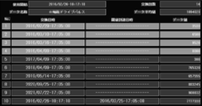
- FIG. 14 is configured such that when the replacement history button 613 relating to the R-axis total drive pulse is pressed, the screen control unit 520 switches to the display unit 218 when the part data name in FIG. 12 is pressed.
- FIG. 14 is a diagram for explaining the present embodiment, and unlike the actual screen, there are portions where the numerical values described do not make sense.
- FIG. 14 shows the use start date and time (2016/2 / 26-18: 17: 18), the name of the part data (R-axis total drive pulse), the number of replacements (14), and the data average value ( 1094023) is displayed.
- FIG. 14 is configured to display the part data at the time of replacement for the past 10 times in order from the oldest item number 1 with respect to the data name (R-axis total drive pulse).
- Item No. 10 is configured to display the latest exchange data.
- the reason for replacement from item number 1 to item number 4 is regular replacement, but the reason for replacement from item number 5 to item number 10 is due to a failure. If the threshold is exceeded at the time of replacement, the date and time when the threshold is exceeded is entered in the threshold arrival date and time column.
- the data column indicates the cumulative value of the part data at the time of replacement.
- the data average value indicates an average value of data values at the time of the past 10 exchanges.
- the screen control unit 520 switches to a maintenance part management replacement execution screen that displays data related to the replacement history of the selected maintenance part. Configured to display.
- FIG. 15 is configured so that when the replacement of the maintenance part actually selected in FIG. 10 is completed, the part maintenance button 602 on the maintenance part management function main screen can be pressed to display. If the replacement factor is due to regular maintenance, the replacement (periodic) button 621 can be displayed by the screen control unit 520 when the replacement (periodic) button 621 is pressed. When the user presses 622, the screen can be displayed by the screen control unit 520.
- This screen (Fig. 15) displays the latest replacement date and time (2021/07 / 22-17: 05: 08) and the total number of previous replacements (13).
- the replacement date and time and the parts data at the time of replacement are stored. If it has already been exchanged 10 times or more, it is deleted from the oldest history. Further, only the latest exchange history information can be canceled.
- This cancel button is configured so that it can be pressed in the case of an erroneous operation causing replacement at the time of a component replacement completion operation. Further, the cancel button is configured to be added to the latest exchange history information so as to save data other than the latest data and not delete the accumulated data up to that time.
- FIG. 16 is configured to display a maintenance part replacement date and time and a cumulative value of all part data at the time of maintenance part replacement.
- parts replacement and maintenance have been set based on the elapsed time after the operation of the device, and there has been a problem that it has not been possible to make a judgment based on numerical values based on the operation status of the parts such as the movement distance of the shaft.
- the device administrator refers to the main screen (FIG. 10) of the maintenance part management function to check the mechanism composed of maintenance parts whose part data exceeds the threshold, It is possible to determine replacement or maintenance by looking at specific numerical values that take into account the operating status of the apparatus in addition to the elapsed time.
- the mechanism composed of the respective maintenance parts is different depending on the configuration difference between the vertical apparatus and the single wafer apparatus, so the selected maintenance parts are different.
- the technical idea in the present invention is the same.
- the component management function in the present embodiment can be applied to a transfer mechanism for transferring a substrate used in a single wafer apparatus.
- the component management function according to this embodiment is applied to a unit configured by a component used in the single wafer apparatus, a mechanism configured by a plurality of components, a plurality of mechanisms, or a combination of components or mechanisms. it can.
- the substrate processing apparatus will be a vertical apparatus. It goes without saying that the same effect as in the single wafer apparatus is achieved.
- a plurality of different usage status data (part data) and threshold values are collectively managed for one replacement part (maintenance part), and the date and time of replacement is Reliability can be improved by presenting the date and time when the threshold value is first reached based on the number of times of use (average, moving average, etc.) in the situation data (part data).
- the warranty period or the number of times of warranty use indicated by the component manufacturer is used as a threshold value, and the replacement time is presented in the date and time based on the number of times of use per day as well as the cumulative number of times. Supports the user's planned system shutdown and parts replacement, and can improve the operating rate.
- (C) According to the present embodiment, it is possible to display a history of factors, date and time, cumulative data, etc. at the time of parts replacement. As a result, the failure rate is grasped, and when the failure rate is high, a proposal such as switching of the parts maker is made to prevent sudden device stop and improve the operation rate.
- parts replacement and maintenance are conventionally set based on the elapsed time after the operation of the equipment, and can be determined by numerical values based on the operation status of the parts, such as the number of pulses of the shaft.
- the device manufacturer apparatus administrator grasps a maintenance part or mechanism whose part data exceeds the threshold by referring to the maintenance part management main screen. In this way, the device manufacturer device administrator can determine replacement and maintenance by referring to the main screen of maintenance parts management and looking at specific numerical values that take into account the operating status of the device in addition to the elapsed time. Become.
- the service engineer of the equipment manufacturer refers to the part data of the maintenance part, for example, after carrying out the failure handling, and displays the graph to see the tendency of the part data, so that the future equipment maintenance Service proposals can be made. Also, it is possible to optimize stock by preparing systematically only maintenance parts that are close to the replacement time. In addition, it is possible to propose to reduce the number of times the apparatus is stopped by collectively exchanging maintenance parts whose replacement and maintenance scheduled dates are close to each other.
- the component management program (component management function) is incorporated in the operation unit 201.
- a data collection controller is provided separately from the operation unit 201, and the controller is configured to execute the component management program. May be.
- this functional configuration receives, for example, a communication unit that transmits and receives various data to and from the operation unit 201, and apparatus data transmitted from the substrate processing apparatus via this communication unit, and refers to the received data.
- parts data related to maintenance parts among the equipment data an equipment data control section for updating the parts data, a display data control section for processing the parts data into screen display data and updating the screen display data, Are configured.
- the screen display may be replaced by the operation unit 201 and a terminal connected for screen reference.
- component management program in the embodiment of the present invention is incorporated in a transport system controller 211 as a transport control unit, a process system controller 212 as a processing control unit, and any controller of the management device. It does not matter.
- the substrate processing apparatus 1 in the embodiment of the present invention can be applied not only to a semiconductor manufacturing apparatus for manufacturing a semiconductor but also to an apparatus for processing a glass substrate such as an LCD device. Needless to say, the present invention is also applicable to various substrate processing apparatuses such as an exposure apparatus, a lithography apparatus, a coating apparatus, and a processing apparatus using plasma. Furthermore, the film formation process can be performed by a process for forming a thin film such as CVD or PVD, a process for forming an oxide film or a nitride film, or a process for forming a film containing metal.
- the maintenance part management that displays the part or the mechanism selected as a management target from each part constituting the apparatus or each mechanism composed of a plurality of parts as a maintenance part
- the screen control unit that displays the screen on the display unit
- the collection unit that collects component data related to the maintenance component
- the cumulative value of the component data and a preset threshold value are compared, and the threshold value is exceeded
- the mechanism and the mechanism are configured by controlling the determination unit that determines the replacement time, the calculation unit that calculates the replacement time, the screen control unit, the collection unit, the determination unit, and the calculation unit, respectively.
- the replacement part is calculated based on an average value of the part data for each predetermined period and a cumulative value of the part data, and the maintenance part including the latest replacement part
- a substrate processing apparatus comprising at least an operation unit configured to display the maintenance parts displayed on the maintenance part management screen so as to be arranged in order from the top in a state in which the maintenance parts are displayed on the display unit.
- the screen control unit includes the mechanism and the replacement time calculated for the component data of each component constituting the mechanism, the latest A button for displaying the replacement time of the maintenance part according to the replacement time is displayed in a color-coded manner on the maintenance part management screen.
- the screen controller when the replacement time of the component data exceeds the threshold value on the button for displaying the replacement time of the maintenance component, the screen controller When the replacement time of the part data is less than one year up to the threshold value, "Date exceeding the threshold value" is displayed, and when the replacement time of the part data is one year or more up to the threshold value, It is configured to display “good”.
- the screen control unit displays a non-display item button on the maintenance component management screen, and when the non-display item button is pressed, the maintenance component is displayed. It is configured to display information on maintenance parts that are not displayed on the management screen.
- the screen control unit displays a button for displaying a replacement timing of the maintenance component on the maintenance component management screen, and displays a replacement timing of the maintenance component.
- a button to display is pressed, for a plurality of parts related to the mechanism, while displaying the threshold value and cumulative value of the part data related to the part, the replacement time of each part and the time until the replacement time are displayed.
- a maintenance part detail screen for displaying the number of days is displayed.
- the screen control unit displays a button for displaying the replacement history of the maintenance component on the maintenance component management screen, and displays the replacement history of the maintenance component.
- a display button is pressed, a maintenance part replacement screen for displaying part replacement information including the number of times the maintenance part has been replaced is displayed.
- the screen control unit includes a data trace button for displaying the component data in a graph on the maintenance component detail screen, and the data trace button is When pressed, the operation unit is configured to display the accumulated value of the component data of the maintenance component on the display unit on a time axis of a predetermined period.
- the screen control unit includes data of a name of the target component data, a date of a reference time, and a cumulative value of the component data for each predetermined period.
- the component data trace graph is displayed by displaying the points in a state where the points are connected by lines.
- the operation unit collects part data corresponding to the mechanism and parts constituting the mechanism, and calculates by integrating or counting up the part data.
- the accumulated value of the component data is compared with a preset threshold value for each component data, and when at least one of the component data exceeds the threshold value, the replacement time is determined. ing.
- the substrate processing apparatus further includes a maintenance part list for setting the part or the mechanism selected as a management target to be displayed as a maintenance part.
- the maintenance parts list is updated so that the maintenance parts including the most recent replacement time are arranged in order from the top, and the screen control unit displays the maintenance part management screen on the display unit based on the updated result. It is configured to
- the said components selected as management object from each mechanism which comprises each component or several components which comprise an apparatus, or the maintenance component which displays the said mechanism as a maintenance component The screen control unit that displays the management screen on the display unit, the collection unit that collects component data related to the maintenance component, the cumulative value of the component data and a preset threshold value are compared, and the threshold value is exceeded
- the mechanism and the mechanism are configured by controlling the determination unit that determines the replacement time, the calculation unit that calculates the replacement time, the screen control unit, the collection unit, the determination unit, and the calculation unit, respectively.
- the replacement time is calculated based on an average value of the part data for each predetermined period and a cumulative value of the part data, and the maintenance including the most recent replacement time
- the maintenance parts management operation unit controller is configured to be displayed on the display unit while updating the maintenance component displayed on the screen is provided so as to align the top of goods in order.
- the part selected as the management target from each part constituting the apparatus or each mechanism constituted by a plurality of parts or the maintenance that displays the mechanism as a maintenance part A screen control unit for displaying a component management screen on a display unit, a determination unit for determining a replacement time when a cumulative value of component data related to the maintenance component exceeds a threshold value, and a calculation unit for calculating the replacement time At least one of a procedure for collecting component data corresponding to each of the mechanism and the components constituting the mechanism, and a procedure for comparing a cumulative value of the component data with a preset threshold value.
- the procedure for determining the replacement time, and the mechanism and the component data of each of the components constituting the mechanism A procedure for calculating the replacement time based on an average value of the part data and a cumulative value of the part data for each predetermined period, and the maintenance so that the maintenance parts including the most recent replacement time are arranged in order from the top.
- a component management program for causing the operation unit controller to execute a procedure for updating the maintenance component displayed on the component management screen and a procedure for displaying the maintenance component management screen on the display unit, or the component management program is recorded.
- a computer readable recording medium is provided.
- the part or the mechanism selected as a management target from the parts constituting the apparatus or the mechanism constituted by a plurality of parts is set as a display target as a maintenance part.
- a screen control unit that expands the maintenance part list and displays a maintenance part management screen on the display unit, a collection unit that collects part data related to the maintenance part, a cumulative value of the part data, and a preset threshold value
- the determination unit that determines the replacement time
- the calculation unit that calculates the replacement time
- the screen control unit, the collection unit, the determination unit, and the calculation unit are respectively controlled.
- the component data corresponding to each of the mechanism and the components constituting the mechanism is collected, and the cumulative value of the component data calculated by integrating or counting up the component data is set in advance.
- Each of the component data is compared with a threshold value, and when at least one of the component data exceeds the threshold value, the replacement time is determined, and the mechanism and the component data of each component constituting the mechanism are determined.
- the replacement time is calculated based on the average value of the part data for each predetermined period and the cumulative value of the part data, and the maintenance part list is arranged in order from the top in order from the maintenance part including the most recent replacement time.
- a substrate processing apparatus comprising at least a control unit configured to update and display the maintenance part management screen on a display unit.
- the screen control unit displays a hidden item button on the maintenance part management screen, and when the hidden item button is pressed, the maintenance part is displayed. It is configured to display information on non-displayable maintenance parts that are leaked from the list.
- the screen control unit displays a button for displaying a replacement time of the maintenance part and a replacement history of the maintenance part on the maintenance part management screen.
- the button for displaying the replacement time of the maintenance part is pressed, the threshold value and the cumulative value of the part data related to the part are displayed for a plurality of parts related to the mechanism.
- it is configured to display a maintenance part detail screen that displays the replacement time of each part and the number of days until the replacement time, and when the button for displaying the replacement history of the maintenance part is pressed, the maintenance part A maintenance part replacement screen for displaying part replacement information including the number of times of replacement is displayed.
- the present invention can be applied to management of components constituting a substrate processing apparatus that processes a substrate.
Landscapes
- Engineering & Computer Science (AREA)
- Physics & Mathematics (AREA)
- General Physics & Mathematics (AREA)
- Automation & Control Theory (AREA)
- Manufacturing & Machinery (AREA)
- Human Computer Interaction (AREA)
- Business, Economics & Management (AREA)
- Human Resources & Organizations (AREA)
- Economics (AREA)
- Entrepreneurship & Innovation (AREA)
- Marketing (AREA)
- Operations Research (AREA)
- Quality & Reliability (AREA)
- Strategic Management (AREA)
- Tourism & Hospitality (AREA)
- General Business, Economics & Management (AREA)
- Theoretical Computer Science (AREA)
- Container, Conveyance, Adherence, Positioning, Of Wafer (AREA)
Abstract
Description
Claims (11)
- 装置を構成する各部品若しくは複数の部品で構成される各機構から管理対象として選定された前記部品又は前記機構を保守部品として表示する保守部品管理画面を表示部に表示させる画面制御部と、前記保守部品に関連する部品データを収集する収集部と、前記部品データの累積値と予め設定された閾値を比較し、該閾値を超えていた場合、交換時期と判定する判定部と、前記交換時期を算出する演算部と、前記画面制御部、前記収集部、前記判定部、前記演算部をそれぞれ制御して、前記機構及び前記機構を構成する部品の前記部品データについて、所定周期毎の前記部品データの平均値と前記部品データの累積値に基づいてそれぞれ前記交換時期を算出し、最も直近の前記交換時期を含む前記保守部品から順に上から並ぶよう前記保守部品管理画面に表示された前記保守部品を更新した状態で前記表示部に表示させるよう構成されている操作部と、を少なくとも備えた基板処理装置。
- 前記画面制御部は、前記機構及び前記機構を構成する部品それぞれの前記部品データについて算出された前記交換時期のうち、最も直近の前記交換時期に応じて前記保守部品の交換時期を表示するボタンを前記保守部品管理画面に色分け表示するよう構成されている請求項1記載の基板処理装置。
- 前記画面制御部は、前記保守部品管理画面に非表示アイテムボタンを表示し、前記非表示アイテムボタンが押下されると、前記保守部品管理画面に表示されていない保守部品の情報を表示するよう構成されている請求項1記載の基板処理装置。
- 前記画面制御部は、前記保守部品管理画面に、前記保守部品の交換時期を表示するボタンを表示し、前記保守部品の交換時期を表示するボタンが押下されると、前記機構に関連する複数の部品に対して、前記部品に関連する前記部品データの閾値及び累積値を表示しつつ、各部品の交換時期と該交換時期までの日数を表示する保守部品詳細画面を表示するよう構成されている請求項1記載の基板処理装置。
- 前記画面制御部は、前記保守部品管理画面に、前記保守部品の交換履歴を表示するボタンを表示し、前記保守部品の交換履歴を表示するボタンが押下されると、前記保守部品を交換した回数を含む部品交換情報を表示する保守部品交換画面を表示するよう構成されている請求項1記載の基板処理装置。
- 前記画面制御部は、前記保守部品詳細画面に前記部品データをグラフ表示するデータトレースボタンを備え、前記データトレースボタンが押下されると、前記操作部は、前記保守部品の前記部品データの累積値を所定期間の時間軸で前記表示部に表示させるよう構成されている請求項4又は請求項5に記載の基板処理装置。
- 前記画面制御部は、対象の前記部品データの名称と、基準時刻の日付と、前記所定期間毎の前記部品データの累積値のデータ点をそれぞれ線で結んだ状態でそれぞれ表示することにより、前記部品データのトレースグラフを表示するよう構成されている請求項6記載の基板処理装置。
- 前記操作部は、前記機構及び前記機構を構成する部品にそれぞれ応じた部品データを収集し、前記部品データの積算若しくはカウントアップにより算出される前記部品データの累積値と、予め設定された各部品データに対する閾値と、をそれぞれ比較し、少なくとも一つの前記部品データが前記閾値を超えていた場合、前記交換時期と判定するよう構成されている請求項1記載の基板処理装置。
- 更に管理対象として選定された前記部品又は前記機構を保守部品として表示対象に設定する保守部品リストを有し、前記操作部は、最も直近の前記交換時期を含む前記保守部品から順に上から並ぶように前記保守部品リストを更新し、前記画面制御部は、前記更新した結果に基いて、前記保守部品管理画面を前記表示部に表示するよう構成されている請求項1記載の基板処理装置。
- 装置を構成する各部品若しくは複数の部品で構成される各機構から管理対象として選定された前記部品又は前記機構を保守部品として表示する保守部品管理画面を表示部に表示させる画面制御部と、前記保守部品に関連する部品データを収集する収集部と、前記部品データの累積値と予め設定された閾値を比較し、該閾値を超えていた場合、交換時期と判定する判定部と、前記交換時期を算出する演算部と、前記画面制御部、前記収集部、前記判定部、前記演算部をそれぞれ制御して、前記機構及び前記機構を構成する部品の前記部品データについて、所定周期毎の前記部品データの平均値と前記部品データの累積値に基づいてそれぞれ前記交換時期を算出し、最も直近の前記交換時期を含む前記保守部品から順に上から並ぶよう前記保守部品管理画面に表示された前記保守部品を更新した状態で前記表示部に表示させるよう構成されている操作部コントローラ。
- 装置を構成する各部品若しくは複数の部品で構成される各機構から管理対象として選定された前記部品又は前記機構を保守部品として表示する保守部品管理画面を表示部に表示させる画面制御部と、前記保守部品に関連する部品データの累積値が閾値を超えていた場合に交換時期と判定する判定部と、前記交換時期を算出する演算部と、を有する操作部コントローラにおいて、前記機構及び前記機構を構成する部品にそれぞれ応じた部品データを収集する手順と、前記部品データの累積値と予め設定された閾値を比較する手順と、少なくとも一つの前記部品データが前記閾値を超えていた場合、前記交換時期と判定する手順と、前記機構及び前記機構を構成する部品それぞれの前記部品データについて、所定周期毎の前記部品データの平均値と前記部品データの累積値に基づいて前記交換時期を算出する手順と、最も直近の前記交換時期を含む前記保守部品から順に上から並ぶよう前記保守部品管理画面に表示された前記保守部品を更新する手順と、前記保守部品管理画面を前記表示部に表示させる手順と、を操作部コントローラに実行させる部品管理プログラムを記録したコンピュータ読取可能な記録媒体。
Priority Applications (4)
| Application Number | Priority Date | Filing Date | Title |
|---|---|---|---|
| CN201680083301.2A CN108885969B (zh) | 2016-03-14 | 2016-03-14 | 基板处理装置、控制器以及记录介质 |
| PCT/JP2016/057973 WO2017158682A1 (ja) | 2016-03-14 | 2016-03-14 | 基板処理装置、コントローラ及び記録媒体 |
| JP2018505071A JP6581718B2 (ja) | 2016-03-14 | 2016-03-14 | 基板処理装置、コントローラ及び部品管理プログラム |
| US16/128,851 US11663562B2 (en) | 2016-03-14 | 2018-09-12 | Substrate processing apparatus and controller |
Applications Claiming Priority (1)
| Application Number | Priority Date | Filing Date | Title |
|---|---|---|---|
| PCT/JP2016/057973 WO2017158682A1 (ja) | 2016-03-14 | 2016-03-14 | 基板処理装置、コントローラ及び記録媒体 |
Related Child Applications (1)
| Application Number | Title | Priority Date | Filing Date |
|---|---|---|---|
| US16/128,851 Continuation US11663562B2 (en) | 2016-03-14 | 2018-09-12 | Substrate processing apparatus and controller |
Publications (1)
| Publication Number | Publication Date |
|---|---|
| WO2017158682A1 true WO2017158682A1 (ja) | 2017-09-21 |
Family
ID=59852003
Family Applications (1)
| Application Number | Title | Priority Date | Filing Date |
|---|---|---|---|
| PCT/JP2016/057973 Ceased WO2017158682A1 (ja) | 2016-03-14 | 2016-03-14 | 基板処理装置、コントローラ及び記録媒体 |
Country Status (4)
| Country | Link |
|---|---|
| US (1) | US11663562B2 (ja) |
| JP (1) | JP6581718B2 (ja) |
| CN (1) | CN108885969B (ja) |
| WO (1) | WO2017158682A1 (ja) |
Cited By (6)
| Publication number | Priority date | Publication date | Assignee | Title |
|---|---|---|---|---|
| CN109722794A (zh) * | 2017-10-27 | 2019-05-07 | Juki株式会社 | 管理系统、缝纫机及管理装置 |
| JP2020047042A (ja) * | 2018-09-20 | 2020-03-26 | 株式会社日立ハイテクノロジーズ | 自動分析装置 |
| CN112397411A (zh) * | 2019-08-13 | 2021-02-23 | 台湾积体电路制造股份有限公司 | 包含抽出装置的制程系统及其监测方法 |
| WO2023140005A1 (ja) * | 2022-01-19 | 2023-07-27 | 株式会社Screenホールディングス | 支援装置、支援方法および支援プログラム |
| JP2024046055A (ja) * | 2022-09-22 | 2024-04-03 | 株式会社Screenホールディングス | 基板処理装置および基板処理システム |
| KR20250145526A (ko) | 2024-03-28 | 2025-10-13 | 가부시키가이샤 코쿠사이 엘렉트릭 | 표시 방법, 반도체 장치의 제조 방법, 프로그램, 처리 장치, 처리 시스템 및 관리 장치 |
Families Citing this family (8)
| Publication number | Priority date | Publication date | Assignee | Title |
|---|---|---|---|---|
| JP6803145B2 (ja) * | 2016-03-16 | 2020-12-23 | 株式会社イシダ | 装置管理システム |
| US10388548B2 (en) * | 2016-05-27 | 2019-08-20 | Texas Instruments Incorporated | Apparatus and method for operating machinery under uniformly distributed mechanical pressure |
| JP7304692B2 (ja) * | 2018-12-13 | 2023-07-07 | 東京エレクトロン株式会社 | 基板処理方法および基板処理装置 |
| JP2020143333A (ja) * | 2019-03-06 | 2020-09-10 | 株式会社Kokusai Electric | 基板処理装置、半導体装置の製造方法及びプログラム |
| JP7036763B2 (ja) * | 2019-03-28 | 2022-03-15 | ファナック株式会社 | 工具交換時期管理システム |
| JP7570822B2 (ja) | 2020-04-28 | 2024-10-22 | キヤノン株式会社 | 情報処理装置、及び情報処理方法 |
| JP2021174349A (ja) * | 2020-04-28 | 2021-11-01 | キヤノン株式会社 | 情報処理装置、表示制御方法、プログラム、基板処理システム、及び物品の製造方法 |
| JP7556642B2 (ja) * | 2020-12-25 | 2024-09-26 | 東京エレクトロン株式会社 | 情報処理装置、情報処理システム及び部品発注方法 |
Citations (5)
| Publication number | Priority date | Publication date | Assignee | Title |
|---|---|---|---|---|
| JP2000124094A (ja) * | 1998-10-20 | 2000-04-28 | Dainippon Screen Mfg Co Ltd | 基板処理装置およびその故障予測方法 |
| JP2003257808A (ja) * | 2002-03-05 | 2003-09-12 | Toshiba Corp | 半導体製造装置、その管理装置、その部品管理装置、半導体ウェーハ収納容器搬送装置 |
| JP2005195401A (ja) * | 2004-01-05 | 2005-07-21 | Hitachi High-Technologies Corp | 自動分析装置のサポートシステム |
| JP2008127129A (ja) * | 2006-11-17 | 2008-06-05 | Kobelco Cranes Co Ltd | 建設機械用メンテナンス情報管理装置及び建設機械用メンテナンス情報管理方法 |
| JP2012123311A (ja) * | 2010-12-10 | 2012-06-28 | Konica Minolta Business Technologies Inc | 在庫管理装置、在庫管理システム、画像処理装置、在庫管理方法、在庫管理プログラム |
Family Cites Families (24)
| Publication number | Priority date | Publication date | Assignee | Title |
|---|---|---|---|---|
| JP3300816B2 (ja) | 1992-02-27 | 2002-07-08 | 株式会社日立国際電気 | 半導体製造装置管理方法及びその装置 |
| US6138056A (en) * | 1998-03-02 | 2000-10-24 | Therwood Corporation | System and method for maintenance and repair of CNC machines |
| EP1273718B1 (en) * | 2000-03-31 | 2012-08-01 | Hitachi Construction Machinery Co., Ltd. | Method and system for managing construction machine |
| US8655698B2 (en) * | 2000-10-17 | 2014-02-18 | Accenture Global Services Limited | Performance-based logistics for aerospace and defense programs |
| US7124059B2 (en) * | 2000-10-17 | 2006-10-17 | Accenture Global Services Gmbh | Managing maintenance for an item of equipment |
| US6980959B1 (en) * | 2000-10-17 | 2005-12-27 | Accenture Llp | Configuring mechanical equipment |
| US7010386B2 (en) * | 2002-03-22 | 2006-03-07 | Mcdonnell Ryan P | Tool wear monitoring system |
| US7117050B2 (en) * | 2002-11-08 | 2006-10-03 | Toshiba Kikai Kabushiki Kaisha | Management supporting apparatus, management supporting system, management supporting method, management supporting program, and a recording medium with the program recorded therein |
| JP2004249718A (ja) * | 2003-01-30 | 2004-09-09 | Toshiba Mach Co Ltd | 産業機械の表示装置及び履歴収集システム |
| JP2008112209A (ja) * | 2006-10-27 | 2008-05-15 | Omron Corp | 稼働状態モニタリング装置、稼働状態モニタリング方法、およびプログラム |
| JP4982196B2 (ja) * | 2007-01-29 | 2012-07-25 | 株式会社リコー | 交換部品発注処理装置、交換部品発注処理方法及び交換部品発注処理プログラム |
| JP5228420B2 (ja) * | 2007-09-14 | 2013-07-03 | 株式会社リコー | 画像形成装置,交換対象部材の情報登録方法,プログラム,および記録媒体 |
| US20100064235A1 (en) * | 2008-08-26 | 2010-03-11 | Walls Marshall G | Visual Intuitive Interactive Interwoven Multi-Layered Maintenance Support GUI |
| JP5850657B2 (ja) * | 2011-07-01 | 2016-02-03 | キヤノン株式会社 | 情報処理装置とその制御方法、プログラム、並びに情報処理システム |
| JP5746128B2 (ja) * | 2012-12-04 | 2015-07-08 | ファナック株式会社 | 保守部品の交換時期判断機能を有する工作機械 |
| JP5681224B2 (ja) * | 2013-03-07 | 2015-03-04 | ファナック株式会社 | 部品点検時期通知機能を有する機械の数値制御装置 |
| US9218694B1 (en) * | 2013-08-12 | 2015-12-22 | The Boeing Company | Recommendations for time to replace parts on machines |
| WO2015166637A1 (ja) * | 2014-04-28 | 2015-11-05 | 日本電気株式会社 | メンテナンス時期決定装置、劣化予測システム、劣化予測方法および記録媒体 |
| US20160034329A1 (en) * | 2014-07-31 | 2016-02-04 | Western Integrated Technologies, Inc. | Correlation and prediction analysis of collected data |
| WO2016157402A1 (ja) * | 2015-03-31 | 2016-10-06 | 株式会社日立国際電気 | 基板処理装置、半導体装置の製造方法及び記録媒体 |
| JP6298797B2 (ja) * | 2015-06-18 | 2018-03-20 | 日立建機株式会社 | 建設機械の交換品管理システム |
| JP6285403B2 (ja) * | 2015-11-30 | 2018-02-28 | ファナック株式会社 | 製造機械の故障を予測するセル制御装置および生産システム |
| TWI570587B (zh) * | 2015-12-07 | 2017-02-11 | 財團法人工業技術研究院 | 半導體機台零件剩餘壽命預測系統與方法 |
| JP6301902B2 (ja) * | 2015-12-21 | 2018-03-28 | ファナック株式会社 | 保守時期予測システム及び保守時期予測装置 |
-
2016
- 2016-03-14 WO PCT/JP2016/057973 patent/WO2017158682A1/ja not_active Ceased
- 2016-03-14 JP JP2018505071A patent/JP6581718B2/ja active Active
- 2016-03-14 CN CN201680083301.2A patent/CN108885969B/zh active Active
-
2018
- 2018-09-12 US US16/128,851 patent/US11663562B2/en active Active
Patent Citations (5)
| Publication number | Priority date | Publication date | Assignee | Title |
|---|---|---|---|---|
| JP2000124094A (ja) * | 1998-10-20 | 2000-04-28 | Dainippon Screen Mfg Co Ltd | 基板処理装置およびその故障予測方法 |
| JP2003257808A (ja) * | 2002-03-05 | 2003-09-12 | Toshiba Corp | 半導体製造装置、その管理装置、その部品管理装置、半導体ウェーハ収納容器搬送装置 |
| JP2005195401A (ja) * | 2004-01-05 | 2005-07-21 | Hitachi High-Technologies Corp | 自動分析装置のサポートシステム |
| JP2008127129A (ja) * | 2006-11-17 | 2008-06-05 | Kobelco Cranes Co Ltd | 建設機械用メンテナンス情報管理装置及び建設機械用メンテナンス情報管理方法 |
| JP2012123311A (ja) * | 2010-12-10 | 2012-06-28 | Konica Minolta Business Technologies Inc | 在庫管理装置、在庫管理システム、画像処理装置、在庫管理方法、在庫管理プログラム |
Cited By (10)
| Publication number | Priority date | Publication date | Assignee | Title |
|---|---|---|---|---|
| CN109722794A (zh) * | 2017-10-27 | 2019-05-07 | Juki株式会社 | 管理系统、缝纫机及管理装置 |
| JP2020047042A (ja) * | 2018-09-20 | 2020-03-26 | 株式会社日立ハイテクノロジーズ | 自動分析装置 |
| CN110927075A (zh) * | 2018-09-20 | 2020-03-27 | 株式会社日立高新技术 | 自动分析装置 |
| JP7100411B2 (ja) | 2018-09-20 | 2022-07-13 | 株式会社日立ハイテク | 自動分析装置 |
| CN112397411A (zh) * | 2019-08-13 | 2021-02-23 | 台湾积体电路制造股份有限公司 | 包含抽出装置的制程系统及其监测方法 |
| WO2023140005A1 (ja) * | 2022-01-19 | 2023-07-27 | 株式会社Screenホールディングス | 支援装置、支援方法および支援プログラム |
| JP2023105744A (ja) * | 2022-01-19 | 2023-07-31 | 株式会社Screenホールディングス | 支援装置、支援方法および支援プログラム |
| JP7822183B2 (ja) | 2022-01-19 | 2026-03-02 | 株式会社Screenホールディングス | 支援装置、支援方法および支援プログラム |
| JP2024046055A (ja) * | 2022-09-22 | 2024-04-03 | 株式会社Screenホールディングス | 基板処理装置および基板処理システム |
| KR20250145526A (ko) | 2024-03-28 | 2025-10-13 | 가부시키가이샤 코쿠사이 엘렉트릭 | 표시 방법, 반도체 장치의 제조 방법, 프로그램, 처리 장치, 처리 시스템 및 관리 장치 |
Also Published As
| Publication number | Publication date |
|---|---|
| JP6581718B2 (ja) | 2019-09-25 |
| CN108885969B (zh) | 2023-08-15 |
| US20190012847A1 (en) | 2019-01-10 |
| JPWO2017158682A1 (ja) | 2018-12-13 |
| US11663562B2 (en) | 2023-05-30 |
| CN108885969A (zh) | 2018-11-23 |
Similar Documents
| Publication | Publication Date | Title |
|---|---|---|
| JP6581718B2 (ja) | 基板処理装置、コントローラ及び部品管理プログラム | |
| JP6446537B2 (ja) | 基板処理装置、半導体装置の製造方法及びプログラム | |
| JP5774331B2 (ja) | 基板処理システム、管理装置、データ解析方法、及びデータ解析プログラム | |
| TWI511075B (zh) | 管理裝置、基板處理系統、資料分析方法以及電腦可讀取記錄媒體 | |
| JP6186000B2 (ja) | 基板処理装置のメンテナンス方法、半導体装置の製造方法、基板処理装置、及び基板処理装置のメンテナンスプログラム | |
| CN108885970B (zh) | 基板处理装置、装置管理控制器以及记录介质 | |
| JP2017194951A (ja) | 基板処理装置、装置管理コントローラ、及びプログラム | |
| JPWO2014115643A1 (ja) | 基板処理装置の異常判定方法、異常判定装置、及び基板処理システム並びに記録媒体 | |
| CN112740358B (zh) | 基板处理装置、半导体装置的制造方法以及记录介质 | |
| JP4917660B2 (ja) | 基板処理装置、基板処理装置の制御方法、半導体デバイスの製造方法、装置状態遷移方法、基板処理装置の保守方法及び状態遷移プログラム | |
| JP5600503B2 (ja) | 統計解析方法、基板処理システムおよびプログラム | |
| JP2015106575A (ja) | 基板処理装置、基板処理装置の制御方法、制御プログラム及び半導体装置の製造方法 | |
| WO2012035965A1 (ja) | 基板処理システム及び基板処理装置の表示方法 | |
| JP2017002353A (ja) | 基板処理装置及び半導体装置の製造方法 | |
| JP4486692B2 (ja) | 基板処理装置 | |
| JP6001234B2 (ja) | 基板処理システム、基板処理装置、データ処理方法およびプログラム | |
| JP2013045862A (ja) | 基板処理システム | |
| JP2012060168A (ja) | 基板処理装置、基板処理装置のメンテナンス方法、基板処理装置の制御方法、基板処理装置の保守方法、半導体装置の製造方法及び装置状態遷移方法 | |
| JP2013074039A (ja) | 群管理装置 | |
| JP7713920B2 (ja) | 基板処理装置、半導体装置の製造方法、及びプログラム | |
| JP2010166082A (ja) | 基板処理装置、基板処理装置の表示方法、及び半導体装置の製造方法 | |
| JP2011023589A (ja) | 基板処理システム |
Legal Events
| Date | Code | Title | Description |
|---|---|---|---|
| WWE | Wipo information: entry into national phase |
Ref document number: 2018505071 Country of ref document: JP |
|
| WWE | Wipo information: entry into national phase |
Ref document number: 201680083301.2 Country of ref document: CN |
|
| NENP | Non-entry into the national phase |
Ref country code: DE |
|
| 121 | Ep: the epo has been informed by wipo that ep was designated in this application |
Ref document number: 16894306 Country of ref document: EP Kind code of ref document: A1 |
|
| 122 | Ep: pct application non-entry in european phase |
Ref document number: 16894306 Country of ref document: EP Kind code of ref document: A1 |