WO2017104034A1 - バッテリ固定装置 - Google Patents
バッテリ固定装置 Download PDFInfo
- Publication number
- WO2017104034A1 WO2017104034A1 PCT/JP2015/085294 JP2015085294W WO2017104034A1 WO 2017104034 A1 WO2017104034 A1 WO 2017104034A1 JP 2015085294 W JP2015085294 W JP 2015085294W WO 2017104034 A1 WO2017104034 A1 WO 2017104034A1
- Authority
- WO
- WIPO (PCT)
- Prior art keywords
- fixing device
- batteries
- retainer
- battery fixing
- battery
- Prior art date
Links
Images


Classifications
-
- B—PERFORMING OPERATIONS; TRANSPORTING
- B60—VEHICLES IN GENERAL
- B60R—VEHICLES, VEHICLE FITTINGS, OR VEHICLE PARTS, NOT OTHERWISE PROVIDED FOR
- B60R16/00—Electric or fluid circuits specially adapted for vehicles and not otherwise provided for; Arrangement of elements of electric or fluid circuits specially adapted for vehicles and not otherwise provided for
- B60R16/02—Electric or fluid circuits specially adapted for vehicles and not otherwise provided for; Arrangement of elements of electric or fluid circuits specially adapted for vehicles and not otherwise provided for electric constitutive elements
- B60R16/04—Arrangement of batteries
-
- H—ELECTRICITY
- H01—ELECTRIC ELEMENTS
- H01M—PROCESSES OR MEANS, e.g. BATTERIES, FOR THE DIRECT CONVERSION OF CHEMICAL ENERGY INTO ELECTRICAL ENERGY
- H01M50/00—Constructional details or processes of manufacture of the non-active parts of electrochemical cells other than fuel cells, e.g. hybrid cells
- H01M50/20—Mountings; Secondary casings or frames; Racks, modules or packs; Suspension devices; Shock absorbers; Transport or carrying devices; Holders
- H01M50/204—Racks, modules or packs for multiple batteries or multiple cells
-
- H—ELECTRICITY
- H01—ELECTRIC ELEMENTS
- H01M—PROCESSES OR MEANS, e.g. BATTERIES, FOR THE DIRECT CONVERSION OF CHEMICAL ENERGY INTO ELECTRICAL ENERGY
- H01M50/00—Constructional details or processes of manufacture of the non-active parts of electrochemical cells other than fuel cells, e.g. hybrid cells
- H01M50/20—Mountings; Secondary casings or frames; Racks, modules or packs; Suspension devices; Shock absorbers; Transport or carrying devices; Holders
- H01M50/249—Mountings; Secondary casings or frames; Racks, modules or packs; Suspension devices; Shock absorbers; Transport or carrying devices; Holders specially adapted for aircraft or vehicles, e.g. cars or trains
-
- H—ELECTRICITY
- H01—ELECTRIC ELEMENTS
- H01M—PROCESSES OR MEANS, e.g. BATTERIES, FOR THE DIRECT CONVERSION OF CHEMICAL ENERGY INTO ELECTRICAL ENERGY
- H01M50/00—Constructional details or processes of manufacture of the non-active parts of electrochemical cells other than fuel cells, e.g. hybrid cells
- H01M50/20—Mountings; Secondary casings or frames; Racks, modules or packs; Suspension devices; Shock absorbers; Transport or carrying devices; Holders
- H01M50/262—Mountings; Secondary casings or frames; Racks, modules or packs; Suspension devices; Shock absorbers; Transport or carrying devices; Holders with fastening means, e.g. locks
-
- B—PERFORMING OPERATIONS; TRANSPORTING
- B60—VEHICLES IN GENERAL
- B60Y—INDEXING SCHEME RELATING TO ASPECTS CROSS-CUTTING VEHICLE TECHNOLOGY
- B60Y2200/00—Type of vehicle
- B60Y2200/10—Road Vehicles
- B60Y2200/14—Trucks; Load vehicles, Busses
-
- Y—GENERAL TAGGING OF NEW TECHNOLOGICAL DEVELOPMENTS; GENERAL TAGGING OF CROSS-SECTIONAL TECHNOLOGIES SPANNING OVER SEVERAL SECTIONS OF THE IPC; TECHNICAL SUBJECTS COVERED BY FORMER USPC CROSS-REFERENCE ART COLLECTIONS [XRACs] AND DIGESTS
- Y02—TECHNOLOGIES OR APPLICATIONS FOR MITIGATION OR ADAPTATION AGAINST CLIMATE CHANGE
- Y02E—REDUCTION OF GREENHOUSE GAS [GHG] EMISSIONS, RELATED TO ENERGY GENERATION, TRANSMISSION OR DISTRIBUTION
- Y02E60/00—Enabling technologies; Technologies with a potential or indirect contribution to GHG emissions mitigation
- Y02E60/10—Energy storage using batteries
Definitions
- the present invention relates to a battery fixing device that fixes two batteries in parallel.
- Patent Document 1 a battery in which two batteries are arranged in parallel and fixed A fixing device is used.
- the battery fixing device includes a receiving member on which two batteries are arranged in parallel, an outer shoulder portion of the batteries arranged in parallel and three retainers (holding members) for locking between the batteries, and a retainer receiving member. And six rods pressed toward the
- an object of the present invention is to provide a battery fixing device with improved battery attachment / detachment workability.
- the battery fixing device includes a receiving member that is placed side by side in parallel with the two batteries spaced apart, a retainer that partially hangs between the two batteries and that is locked to the shoulders facing the two batteries, The base end portion is fixed to the receiving member in the extending direction of the retainer, the two rods having the distal end portion penetrating the both end portions of the retainer, and the two nuts screwed to the distal end portion of the rod penetrating the retainer; Have The rod passes through the retainer within a range where the two batteries face each other.
- the battery fixing device includes a receiving member for placing a plurality of batteries in parallel, two retainers that are respectively locked to outer shoulders of the plurality of batteries, and a surface perpendicular to the direction in which the plurality of batteries are disposed, And two rotating plates that are rotatably fixed around an axis parallel to the mounting surface of the plurality of batteries.
- the battery fixing device includes a base end portion fixed to a portion located on the opposite side of the left and right sides of the rotation center of each rotating plate so that the base end portion can be relatively rotated, and the distal end portion passes through both end portions of the retainer.
- the rod further includes four nuts that are screwed into the other end portion of the rod penetrating the retainer.
- FIG. 1 shows an example of a track layout.
- a truck is an example of a vehicle.
- the track 100 includes a parallel ladder-shaped frame 200 and a cabin 300 mounted on the front portion of the frame 200.
- the frame 200 includes a pair of left and right side frames 220 extending in parallel with the vehicle front-rear direction and a plurality of cross members 240 extending in the vehicle width direction and connecting the pair of left and right side frames 220.
- parallel is not limited to perfect parallelism, but may be a level that can be recognized as parallel (hereinafter the same).
- the frame 200 becomes a basic skeleton of the truck 100, and an engine, a power transmission device, a suspension, and the like are attached thereto.
- An engine (not shown) is mounted below the cabin 300.
- the engine output is transmitted to the left and right rear wheels 480 as drive wheels via the transmission 400, the propeller shaft 420, the differential carrier 440, and the drive axle 460.
- a dead axle 500 is attached to the rear of the left and right rear wheels 480, and left and right rear wheels 520 as driven wheels at both ends thereof are rotatably supported.
- An exhaust purification device 540, a battery fixing device 560, and an air reservoir tank 580 are arranged on the outer side surface of the side frame 220 located between the cabin 300 and the rear wheel 480 on the right side of the vehicle from the front to the rear of the vehicle. Are installed in this order.
- the reducing agent used in the exhaust emission control device 540 is stored on the outer surface of the side frame 220 located on the left side of the vehicle and between the cabin 300 and the rear wheel 480 from the front to the rear of the vehicle.
- the reducing agent tank 600 and the fuel tank 620 are attached in this order.
- the battery fixing device 560 is not limited to the illustrated position, and can be attached to other positions such as the front surface of the exhaust purification device 540 and the outer surface of the side frame 220 positioned on the left side of the vehicle.
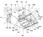
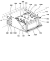
- FIG. 2 to 4 show a first embodiment of the battery fixing device 560.
- the battery fixing device 560 is attached to the outer surface of the side frame 220 by a fastener 660 including a bolt, a washer, and a nut via a bracket 640 having bosses formed at two positions spaced apart in the vertical direction.
- the battery fixing device 560 is partially suspended between the two batteries 680 and the receiving member 562 that is placed side by side in parallel with the two batteries 680, and is locked to the opposite shoulders of the two batteries 680.
- One retainer 564 the battery fixing device 560 has a base end portion fixed to the receiving member 562 in the extending direction of the retainer 564 and two rods 566 whose tip portions pass through both end portions of the retainer 564 and the retainer 564. And two nuts 568 that are screwed into the tip of the rod 566.
- the rod 566 passes through the retainer 564 within a range where the two batteries 680 face each other.
- two batteries 680 are arranged in parallel in the vehicle width direction and fixed, but two batteries 680 may be arranged in parallel in the vehicle front-rear direction (hereinafter the same).
- the receiving member 562 has a rectangular parallelepiped shape that opens toward the outside of the vehicle width and above the vehicle, and includes, for example, a bottom plate 562A, a pair of side plates 562B, and a pair of battery retainers 562C made of a thin steel plate.
- the rectangular parallelepiped shape is not limited to a complete rectangular parallelepiped shape, but may be a level that can be recognized as a rectangular parallelepiped shape by appearance (the same applies hereinafter).
- the bottom plate 562A has a rectangular shape with a plate surface positioned on a horizontal plane defined in the vehicle width direction and the vehicle front-rear direction, and two batteries 680 are placed in parallel on the upper surface.
- the rectangular shape is not limited to a complete rectangular shape, but may be a level that can be recognized as a rectangular shape by appearance (the same applies hereinafter).
- the bottom plate 562A is formed with a plurality of beads (unevenness) BD extending in at least one of the vehicle front-rear direction and the vehicle width direction in order to improve the strength.
- the bottom plate 562A can also be formed with ribs that rise upward from both end portions located inside and outside the vehicle width.
- the side plate 562B has a trapezoidal shape (right-angled trapezoid) with a right angle that rises upward from both ends of the bottom plate 562A in the vehicle front-rear direction and has a shoulder cut outside the vehicle width.
- An attachment plate FP made of a long member having an L-shaped (angle shape) cross section, which is an attachment portion to the bracket 640, is integrated with an end portion of the side plate 562 ⁇ / b> B located on the inner side of the vehicle width.
- the L-shape is not limited to a complete L-shape, but may be a level that can be recognized as an L-shape by appearance (the same applies hereinafter).
- a plurality of bolt insertion holes are formed in the mounting plate FP at positions corresponding to the bosses of the bracket 640.
- a rectangular cover presser CH whose plate surface extends in a horizontal plane is provided on the shoulder portion positioned inward of the vehicle width of the side plate 562B, and the upper surface of the portion positioned inward of the vehicle width of the battery cover 700 is locked. It is integrated.
- the battery retainer 562C is made of a long member having an L-shaped cross section, and is fixed to both end portions of the bottom plate 562A positioned in the vehicle front-rear direction with the material axis extending along the vehicle width direction.
- the pair of battery retainers 562C are spaced apart by a distance corresponding to the width dimension of the battery 680 so that both sides of the battery 680 can be clamped at the portion rising from the bottom plate 562A.
- the edge part located in the vehicle width inside of a pair of battery holder 562C is bent at right angle in the direction which approaches mutually.
- the right angle is not limited to a complete right angle but may be a level that can be recognized as a right angle by appearance (the same applies hereinafter).
- the pair of battery retainers 562C can restrict the movement of the two batteries 680 placed on the bottom plate 562A in the vehicle front-rear direction and the vehicle width inward direction. Furthermore, at least one elongated hole LH extending in the up-down direction for fixing the base end portion of the rod 566 so as to be detachable and swingable is formed in the intermediate portion of the battery retainer 562C.
- the retainer 564 is made of a long member having a hat-shaped cross section that protrudes downward, and has a total length corresponding to the width dimension of the battery 680.
- the hat shape is not limited to a complete hat shape, but may be a level that can be recognized as a hat shape.
- through-holes through which the shaft portions of the rods 566 pass are formed in the protruding portions located at both ends of the retainer 564, respectively. Therefore, when the pair of rods 566 pass through the through hole of the retainer 564, as shown in FIG. 2, the rods 566 are inclined in a C shape so as to approach each other.
- a slope corresponding to the inclination angle of the rod 566 that is, a slope SF perpendicular to the axis of the rod 566 is formed, and a penetration through which the shaft part of the rod 566 passes is formed.
- a hole is formed.
- the slope SF can be formed, for example, by welding a steel material bent into an L shape to the retainer 564.
- the rod 566 is composed of, for example, a J bolt having a base end portion having a J shape, and the base end portion is detachably fixed to the elongated hole LH of the battery retainer 562C. Therefore, the rod 566 can swing at a predetermined angle in at least the vehicle front-rear direction. And the front-end
- a nut 568 is detachably screwed onto the tip of the rod 566 that penetrates the retainer 564 so that the relative position of the retainer 564 with respect to the bottom plate 562A integrated with the battery retainer 562C can be changed.
- the nut 568 be screwed onto the tip of the rod 566, but also a washer that suppresses the loosening can be fitted.
- the battery cover bracket 570 includes a rectangular first member 570A serving as a fixing portion to the bottom plate 562A, an isosceles trapezoidal second member 570B that rises upward from one end of the first member 570A, And a triangular third member 570C extending outward from the vehicle width from the upper end of the second member 570B.
- the isosceles trapezoidal shape and the triangular shape are not limited to the perfect isosceles shape and the triangular shape, but may be such that the isosceles trapezoidal shape and the triangular shape can be recognized visually (the same applies hereinafter).
- a wing nut 570D for fixing the battery cover 700 to the receiving member 562 is provided on the upper surface of the third member 570C via a fixing hole formed in a portion located outside the vehicle width of the battery cover 700. It is detachably screwed.
- An operator who removes and installs the battery 680 places one battery 680 on the upper surface of the receiving member 562 and moves the battery 680 toward the inside of the vehicle width.
- the battery 680 moves to a predetermined position, the lower part of the battery 680 positioned in the vehicle front-rear direction and the vehicle width inward is in contact with the battery retainer 562C.
- the worker fits the base end portion of the rod 566 into the long hole LH of the battery retainer 562C, and places another battery 680 on the upper surface of the receiving member 562. Then, the operator penetrates the distal end portion of the rod 566 through the through hole formed at both end portions of the retainer 564 and the through hole of the slope SF, and loosely engages the nut 568 with the distal end portion. The operator sandwiches the protruding portion of the retainer 564 between the two batteries 680, and further tightens the nut 568 that is screwed into the tip of the rod 566.
- the outer side surface of the battery 680 located outside the vehicle width contacts the battery cover bracket 570, so that the movement of the battery 680 outside the vehicle width is restricted.
- the operating point of the rod 566 with respect to the retainer 564 is within a range where the two batteries 680 face each other, even if the tension of the rod 566 is increased, for example, the retainer 564 is not easily deformed into an arcuate shape. Can be improved.
- the upper surface of the retainer 564 is an inclined surface SF corresponding to the inclination angle of the rod 566, the tension of the rod 566 is efficiently transmitted to the retainer 564, and the battery 680 can be securely fixed. Since the battery 680 is fixed to the receiving member 562 with one retainer 564 and a pair of rods 566, the number of nuts that the operator works is reduced compared to the conventional battery fixing device, and the battery 680 is fixed. Can be easily attached and detached.
- the operator sandwiches a portion of the battery cover 700 located inward of the vehicle width between the upper surface of the battery 680 and the cover presser CH of the side plate 562 ⁇ / b> B.
- the portion located at is fixed with a wing nut 570D of the battery cover bracket 570.
- the worker may perform the above work in reverse. Further, the above work can be slightly changed. For example, the work procedure may be changed, or the battery cover bracket 570 may be temporarily removed when the battery 680 is attached or detached.
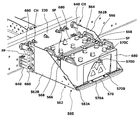
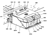
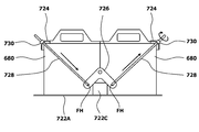
- [Second Embodiment] 5 and 6 show a second embodiment of the battery fixing device 560.
- symbol is demonstrated as 720 from a viewpoint which prevents confusion with the battery fixing device 560 which concerns on 1st Embodiment.
- the battery fixing device 720 includes a receiving member 722 that places two batteries 680 arranged in parallel, and two retainers 724 that are respectively locked to outer shoulders of the two batteries 680. Further, the battery fixing device 720 includes two V-shaped levers that are freely fixed around an axis perpendicular to the arrangement direction of the two batteries 680 (that is, the vehicle width direction) on the boundary surface between the two batteries 680. 740 and four rods whose distal end portions pass through both end portions of the retainer 724 and the base end portion is fixed to a portion located on the opposite side of the left and right sides with the rotation center of each V-shaped lever 726 interposed therebetween. 728 and four nuts 730 that are screwed onto the tip of the rod 728 that passes through the retainer 724.
- the V-shaped lever 726 is an example of the rotating plate.
- the receiving member 722 has a rectangular parallelepiped shape with an opening outside the vehicle width and the top of the vehicle, and includes a bottom plate 722A and a pair of side plates 722B made of, for example, a thin steel plate.
- the bottom plate 722A has a rectangular shape with a plate surface positioned on a horizontal plane defined in the vehicle width direction and the vehicle front-rear direction, and two batteries 680 are placed in parallel on the upper surface.
- the bottom plate 722A is formed with a plurality of beads BD extending in at least one of the vehicle longitudinal direction and the vehicle width direction in order to improve the strength. Note that the bottom plate 722A can also be formed with ribs that rise upward from both end portions located inside and outside the vehicle width.
- the side plate 722B rises upward from both ends in the vehicle front-rear direction of the bottom plate 722A, and has a right trapezoidal shape in which the shoulder located outside the vehicle width is cut obliquely.
- a plurality of bolt insertion holes are formed in the mounting plate FP at positions corresponding to the bosses of the bracket 640.
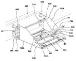
- the retainer 724 is made of a long member having an L-shaped cross section, and has a total length slightly larger than the width dimension of the battery 680. Further, when the retainer 724 is locked to the outer shoulder portion of the battery 680, through holes through which the shaft portion of the rod 728 passes are formed at both ends of the retainer 724 protruding from the battery 680, respectively. Note that the upper surfaces of at least both end portions of the retainer 724 may be inclined according to the inclination angle of the rod 728.
- the V-shaped lever 726 is made of a V-shaped thin plate member whose arms extend at right angles (90 degrees), and the base end of the rod 728 is attached to and detached from the distal ends of both arms.
- Fixing holes FH that are fixed and slidable are formed.
- the fixing hole FH is formed in a central portion of the V-shaped lever 226, that is, a portion that is equidistant L from the rotation center where the axes of both arm portions intersect. Accordingly, the base end portion of the rod 728 is fixed to a portion equidistant from the rotation center of the V-shaped lever 726.
- the V-shaped lever 726 is formed symmetrically with respect to a line that bisects the angle formed by the axes of both arms.
- an elongated hole extending in a direction perpendicular to the extending direction of the arm portion can be formed at the distal end portion of both arm portions of the V-shaped lever 726 instead of the fixing hole FH.
- the rotation center of the V-shaped lever 726 is fixed to the tip of the lever bracket 722C having an inverted V-shape, that is, an L-shape in a side view in a state of being convex upward.
- the base end portion of the lever bracket 722C that is, the lower surface having an L-shaped short side as one side is fixed to the upper surface of the bottom plate 722A so that the side surface having the long side as one side extends along the vehicle width direction.
- the lever bracket 722 ⁇ / b> C has the rotation shaft of the V-shaped lever 726 positioned on the boundary surface between the two batteries 680, and is locked to the plate surface of the V-shaped lever 726 and the outer shoulders of the two batteries 680.
- the retainer 724 is disposed so that the through hole of the retainer 724 is on the same plane. Further, at the distal end of the base end portion of the lever bracket 722C, at a position corresponding to the width dimension of the battery 680, a rectangular shape that rises upward from the battery 680 in order to restrict movement of the battery 680 in the vehicle front-rear direction.
- the battery presser BH is integrated.
- the rod 728 includes, for example, a J bolt whose base end portion has a J shape, and the base end portion is detachably fitted into the fixing hole FH of the V-shaped lever 726. Therefore, the rod 728 can swing at least in the vehicle width direction.
- the distal end of the rod 728 passes through the through hole of the retainer 724 and protrudes upward from the upper surface of the retainer 724.
- a nut 730 is detachably screwed to the tip of the rod 728 that penetrates the retainer 724 so that the relative position of the retainer 724 with respect to the fixing hole FH of the V-shaped lever 726 can be changed.
- a nut 730 is not only screwed into the tip portion of the rod 728, but a washer that suppresses the loosening can be fitted.
- the base end portion of the rod 728 Prior to the work of attaching and detaching the battery 680, as shown in FIG. 5, the base end portion of the rod 728 is fitted and fixed to the fixing hole FH of the V-shaped lever 726, and the distal end portion of the rod 728 is fixed to the retainer 724.
- the nut 730 is screwed into the tip portion of the through hole. Further, with respect to the retainer 724 located inside the vehicle width, the position of the nut 730 that is screwed to the tip of the rod 728 that penetrates the retainer 724 is adjusted in accordance with the size of the battery 680.
- An operator who attaches / detaches the battery 680 places one battery 680 on the receiving member 722, and holds the retainer 724 on the outer shoulder of the battery 680, while facing the retainer 724 toward the inside of the vehicle width. Move. In addition, the worker places another battery 680 on the receiving member 722 while retracting the retainer 724 engaged with the outer shoulder of the battery 680 placed outside the vehicle width upward. Is moved inward in the vehicle width so as to contact the battery 680 placed inward in the vehicle width. Further, the operator lowers the retainer 724 that has been retracted upward, and locks it to the outer shoulder of the battery 680 placed outside the vehicle width.
- both lower portions of the battery 680 positioned in the vehicle longitudinal direction are in contact with the battery presser BH of the lever bracket 722C, the movement of the battery 680 in the vehicle longitudinal direction is restricted. Further, the two outer shoulders of the battery 680 placed side by side are pressed against the fixing hole FH of the V-shaped lever 726 by the retainer 724 and the rod 728, so that the vehicle of the battery 680 Movement in the width direction and the vehicle vertical direction is restricted.
- the battery 680 can be fixed to the receiving member 722 only by tightening the nut 730 of the rod 728 that penetrates the retainer 724 located outside the vehicle width, so that the operator can compare with the conventional battery fixing device.
- the number of nuts to be operated is reduced, and the battery 680 can be easily attached and detached.
- the battery fixing device 720 even if the gap between the battery 680 and the vehicle body is small, the fixing work by the operator is mainly performed from the outside of the vehicle width, so that the battery 680 can be reliably fixed. it can.
- a cover presser is formed on the side plate 722B, a battery cover bracket is attached to an end portion of the bottom plate 722A located outside the vehicle width, and the battery cover is detachably attached. it can.
- the structure for rotatably supporting the V-shaped lever 726 is not limited to the above-described lever bracket 722C, and the following structure may be employed.
- a circular through hole TH is formed at a predetermined position of the bottom plate 722 ⁇ / b> A of the receiving member 722.
- a stepped cylindrical member 732 having a large-diameter portion located below and having a male screw formed at least in a lower portion of the small-diameter portion is penetrated through the through-hole TH so as to be movable up and down.
- a nut 734 having an inner peripheral surface formed with a female screw is screwed to the male screw that is a small-diameter portion of the cylindrical member 732 and is located between the large-diameter portion and the bottom plate 722A. Further, the center portion of the V-shaped lever 726 is rotatably fixed to a small-diameter portion of the columnar member 732 that protrudes upward from the bottom plate 722A.
- the battery 680 with respect to the receiving member 722 can be simply rotated by rotating the nut 734 screwed to the cylindrical member 732.
- the pressing force can be adjusted.
- the V-shaped lever 726 is rotatably fixed to the cylindrical member 732, even if the relative positions of the pair of retainers 724 with respect to the V-shaped lever 726 are slightly different, the V-shaped lever 726 rotates and shifts.
- the two batteries 680 can be absorbed and fixed to the receiving member 722 with substantially equal pressing force.
- a structure as shown in FIG. 11 can also be adopted.
- a circular through hole TH is formed at a predetermined position of the bottom plate 722A of the receiving member 722.
- a welding nut 736 is welded to a position corresponding to the through hole TH on the lower surface of the bottom plate 722A.
- a bolt 738 such as a hexagon socket head cap screw or a hexagon bolt is screwed into the welding nut 736 from below.
- a nut 740 having a female screw formed at least on the inner peripheral surface is screwed onto the shaft portion of the bolt 738 protruding upward from the bottom plate 722A, and the central portion of the V-shaped lever 726 is rotatably fixed to the peripheral wall. Has been.
- the battery 680 with respect to the receiving member 722 can be simply rotated by rotating the bolt 738 screwed to the welding nut 736.
- the pressing force can be adjusted.
- Other operations and effects are the same as those of the support structure of the V-shaped lever 726 shown in FIG.
- the lever that fixes the base end portion of the rod 728 is not limited to the V-shaped lever 726, and may be, for example, a rotary plate having a rectangular shape, a circular shape, an elliptical shape, or the like.
- a fixing hole FH for fixing the base end portion of the rod 728 so as to be detachable and swingable may be formed at an appropriate position of the rotating plate.
- the battery fixing device 720 is not limited to the two batteries 680, and can fix a plurality of batteries 680.
- the V-shaped lever 726 extends around an axis parallel to the mounting surface of the plurality of batteries 680, that is, in the vehicle front-rear direction on a surface perpendicular to the arrangement direction (vehicle width direction) of the plurality of batteries 680. What is necessary is just to be able to rotate freely around an axis.
Abstract
Description
図1は、トラックのレイアウトの一例を示す。ここで、トラックが、車両の一例として挙げられる。
図2~図4は、バッテリ固定装置560の第1実施形態を示す。
バッテリ固定装置560は、上下方向の離間した2位置にボスが形成されたブラケット640を介して、ボルト、ワッシャ及びナットを含む締結具660によって、サイドフレーム220の外側面に取り付けられる。
バッテリ680を脱着する作業者は、受け部材562の上面にバッテリ680を1つ載置し、このバッテリ680を車幅内方へと向けて移動させる。バッテリ680が所定位置まで移動すると、バッテリ680の車両前後方向及び車幅内方に位置する下部がバッテリ押え562Cに当接するため、バッテリ680の車両前後方向及び車幅内方への移動が規制される。
図5及び図6は、バッテリ固定装置560の第2実施形態を示す。なお、第2実施形態においては、第1実施形態に係るバッテリ固定装置560との混同を防止する観点から、その符号を720として説明する。
受け部材722のボトムプレート722Aの所定位置には、図9に示すように、円形形状の貫通孔THが形成されている。この貫通孔THには、下方に大径部が位置すると共に、少なくとも小径部の下部に雄ねじが形成された段付形状の円柱部材732が上下動可能に貫通されている。また、円柱部材732の小径部であって、その大径部とボトムプレート722Aとの間に位置する雄ねじには、内周面に雌ねじが形成されたナット734が螺合されている。さらに、円柱部材732の小径部であって、ボトムプレート722Aから上方に突出する先端部には、V字レバー726の中央部が回転可能に固定されている。
受け部材722のボトムプレート722Aの所定位置には、円形形状の貫通孔THが形成されている。ボトムプレート722Aの下面であって、貫通孔THに対応する位置には、溶接ナット736が溶接されている。溶接ナット736には、六角穴付きボルト、六角ボルトなどのボルト738が下方から螺合されている。ボトムプレート722Aから上方に突出するボルト738の軸部には、少なくとも内周面に雌ねじが形成されたナット740が螺合されており、その周壁にV字レバー726の中央部が回転可能に固定されている。
220 サイドフレーム
560 バッテリ固定装置
562 受け部材
562C バッテリ押え
564 リテーナ
566 ロッド
568 ナット
570 バッテリカバーブラケット
680 バッテリ
722 受け部材
722C レバーブラケット
724 リテーナ
726 V字レバー(回転プレート)
728 ロッド
730 ナット
732 円柱部材
734 ナット
736 溶接ナット
738 ボルト
740 ナット
SF 斜面
FH 固定孔
Claims (15)
- 2つのバッテリを隔てつつ平行に並べて載置する受け部材と、
前記2つのバッテリの間に部分的に垂下すると共に、前記2つのバッテリの向かい合う肩部に係止する1つのリテーナと、
前記リテーナの延設方向において前記受け部材に基端部が固定されると共に、前記リテーナの両端部を先端部が貫通する2つのロッドと、
前記リテーナを貫通した前記ロッドの先端部に螺合する2つのナットと、
を有し、
前記ロッドは、前記2つのバッテリが向かい合う範囲内で前記リテーナを貫通する、
ことを特徴とするバッテリ固定装置。 - 前記受け部材は、車両前後方向及び車幅方向により規定される水平面上において、少なくとも、前記2つのバッテリの配設方向への移動を規制する、
ことを特徴とする請求項1に記載のバッテリ固定装置。 - 前記リテーナの上面に、前記ロッドの軸線と垂直な斜面が形成され、当該斜面をロッドが貫通する、
ことを特徴とする請求項1又は請求項2に記載のバッテリ固定装置。 - 前記ロッドは、Jボルトからなる、
ことを特徴とする請求項1~請求項3のいずれか1つに記載のバッテリ固定装置。 - 前記受け部材は、車両のサイドフレームの外側面に取り付けられた、
ことを特徴とする請求項1~請求項4のいずれか1つに記載のバッテリ固定装置。 - 前記2つのバッテリは、車幅方向に平行に載置された、
ことを特徴とする請求項1~請求項5のいずれか1つに記載のバッテリ固定装置。 - 複数のバッテリを平行に並べて載置する受け部材と、
前記複数のバッテリの外肩部に夫々係止する2つのリテーナと、
前記複数のバッテリの配設方向に垂直な面上において、当該複数のバッテリの載置面と平行な軸周りに回転自由に固定された2つの回転プレートと、
前記各回転プレートの回転中心を挟んで左右の反対側に位置する部分に基端部が相対回転可能に固定されると共に、前記リテーナの両端部を先端部が貫通する4つのロッドと、
前記リテーナを貫通した前記ロッドの先端部に螺合する4つのナットと、
を有することを特徴とするバッテリ固定装置。 - 前記ロッドの基端部は、前記回転プレートの回転中心から等距離の部分に固定された、
ことを特徴とする請求項7に記載のバッテリ固定装置。 - 前記回転プレートは、逆V字形状をなしている、
ことを特徴とする請求項7又は請求項8に記載のバッテリ固定装置。 - 前記逆V字形状は、90度の角度を有する、
ことを特徴とする請求項9に記載のバッテリ固定装置。 - 前記ロッドは、前記複数のバッテリを固定した状態において、前記回転プレートの逆V字形状に延びる部分に対して90度の角度で延びる、
ことを特徴とする請求項10に記載のバッテリ固定装置。 - 前記回転プレートは、前記受け部材に対する上下位置が調整可能である、
ことを特徴とする請求項7~請求項11に記載のバッテリ固定装置。 - 前記ロッドは、Jボルトからなる、
ことを特徴とする請求項7~請求項12のいずれか1つに記載のバッテリ固定装置。 - 前記受け部材は、車両のサイドフレームの外側面に取り付けられた、
ことを特徴とする請求項7~請求項13のいずれか1つに記載のバッテリ固定装置。 - 前記複数のバッテリは、車幅方向に平行に載置された、
ことを特徴とする請求項7~請求項14のいずれか1つに記載のバッテリ固定装置。
Priority Applications (5)
| Application Number | Priority Date | Filing Date | Title |
|---|---|---|---|
| PCT/JP2015/085294 WO2017104034A1 (ja) | 2015-12-16 | 2015-12-16 | バッテリ固定装置 |
| JP2017555936A JP6710221B2 (ja) | 2015-12-16 | 2015-12-16 | バッテリ固定装置 |
| EP15910724.2A EP3392091B1 (en) | 2015-12-16 | 2015-12-16 | Battery fixing device |
| US16/060,971 US10840488B2 (en) | 2015-12-16 | 2015-12-16 | Battery fixing device |
| CN201580085391.4A CN108430834B (zh) | 2015-12-16 | 2015-12-16 | 电池固定装置 |
Applications Claiming Priority (1)
| Application Number | Priority Date | Filing Date | Title |
|---|---|---|---|
| PCT/JP2015/085294 WO2017104034A1 (ja) | 2015-12-16 | 2015-12-16 | バッテリ固定装置 |
Publications (1)
| Publication Number | Publication Date |
|---|---|
| WO2017104034A1 true WO2017104034A1 (ja) | 2017-06-22 |
Family
ID=59056096
Family Applications (1)
| Application Number | Title | Priority Date | Filing Date |
|---|---|---|---|
| PCT/JP2015/085294 WO2017104034A1 (ja) | 2015-12-16 | 2015-12-16 | バッテリ固定装置 |
Country Status (5)
| Country | Link |
|---|---|
| US (1) | US10840488B2 (ja) |
| EP (1) | EP3392091B1 (ja) |
| JP (1) | JP6710221B2 (ja) |
| CN (1) | CN108430834B (ja) |
| WO (1) | WO2017104034A1 (ja) |
Cited By (10)
| Publication number | Priority date | Publication date | Assignee | Title |
|---|---|---|---|---|
| CN110364652A (zh) * | 2019-06-24 | 2019-10-22 | 浙江畅通科技有限公司 | 可调节蓄电池塑壳 |
| WO2019244858A1 (ja) * | 2018-06-19 | 2019-12-26 | ダイムラー・アクチェンゲゼルシャフト | 車両用バッテリパック支持装置 |
| WO2020003836A1 (ja) * | 2018-06-27 | 2020-01-02 | ダイムラー・アクチェンゲゼルシャフト | 車両用バッテリパック支持装置 |
| WO2020003835A1 (ja) * | 2018-06-27 | 2020-01-02 | ダイムラー・アクチェンゲゼルシャフト | 車両用バッテリパック支持装置 |
| CN112713359A (zh) * | 2020-12-14 | 2021-04-27 | 江苏伟复能源有限公司 | 一种组合式胶体电池 |
| WO2022070906A1 (ja) * | 2020-09-30 | 2022-04-07 | いすゞ自動車株式会社 | 車載物固定用ブラケット |
| WO2022202582A1 (ja) * | 2021-03-23 | 2022-09-29 | いすゞ自動車株式会社 | 車載機器取付装置 |
| WO2022202617A1 (ja) * | 2021-03-24 | 2022-09-29 | いすゞ自動車株式会社 | 車載機器取付装置 |
| JP2022158479A (ja) * | 2021-04-02 | 2022-10-17 | プライムプラネットエナジー&ソリューションズ株式会社 | 車両用電池パックユニットおよびそれを備える車両 |
| JP7249527B1 (ja) | 2021-12-02 | 2023-03-31 | いすゞ自動車株式会社 | 車両のバッテリ固定構造 |
Families Citing this family (5)
| Publication number | Priority date | Publication date | Assignee | Title |
|---|---|---|---|---|
| JP6544311B2 (ja) * | 2016-07-14 | 2019-07-17 | トヨタ自動車株式会社 | 車載機器固定構造 |
| WO2018141513A1 (en) * | 2017-01-31 | 2018-08-09 | Volvo Truck Corporation | A fastening element |
| US11745681B2 (en) * | 2020-11-30 | 2023-09-05 | Nissan North America, Inc. | Battery bracket assembly for a vehicle |
| WO2023065344A1 (en) * | 2021-10-22 | 2023-04-27 | Crown Equipment Corporation | Battery retention blocks for a battery receiving space of a materials handling vehicle, and materials handling vehicles incorporating the same |
| CN114475198A (zh) * | 2022-01-27 | 2022-05-13 | 东风商用车有限公司 | 一种电池支架总成及卡车 |
Citations (9)
| Publication number | Priority date | Publication date | Assignee | Title |
|---|---|---|---|---|
| JPS4324007Y1 (ja) * | 1965-05-20 | 1968-10-09 | ||
| US4129194A (en) * | 1977-07-28 | 1978-12-12 | Eaton Corporation | Hold-down device for storage batteries |
| JPS60138263U (ja) * | 1984-02-27 | 1985-09-12 | 株式会社小松製作所 | バツテリ取付装置 |
| JPH02124661U (ja) * | 1989-03-23 | 1990-10-15 | ||
| JPH0516508U (ja) * | 1991-08-13 | 1993-03-02 | 日野自動車工業株式会社 | バツテリ固定用スペーサ |
| JP2000315484A (ja) * | 1999-04-28 | 2000-11-14 | Hino Motors Ltd | バッテリの取付け装置 |
| JP2003312394A (ja) | 2002-04-23 | 2003-11-06 | Komatsu Ltd | バッテリボックス |
| JP2005297861A (ja) * | 2004-04-14 | 2005-10-27 | Toyota Motor Corp | 電池アセンブリの搭載構造 |
| JP2011126396A (ja) * | 2009-12-17 | 2011-06-30 | Ud Trucks Corp | バッテリ固定装置 |
Family Cites Families (43)
| Publication number | Priority date | Publication date | Assignee | Title |
|---|---|---|---|---|
| USRE25480E (en) * | 1963-11-12 | Battery retainer means | ||
| US2022595A (en) * | 1932-12-19 | 1935-11-26 | Gowing Nathan Howard | Battery protector |
| US2009199A (en) * | 1934-05-07 | 1935-07-23 | Milton W Pehotsky | Battery bracket |
| US2104768A (en) * | 1936-08-21 | 1938-01-11 | American Forging & Socket Co | Storage battery installation |
| US2326481A (en) * | 1941-07-21 | 1943-08-10 | Harvey E Meyer | Battery hold-down |
| US2514056A (en) * | 1947-10-20 | 1950-07-04 | Hatfield Samuel | Battery support |
| US2480202A (en) * | 1948-02-10 | 1949-08-30 | Elmer D Stassen | Battery holder |
| US2802540A (en) * | 1954-04-19 | 1957-08-13 | Gen Motors Corp | Load support mounted for retraction into vehicle compartment |
| US2833363A (en) * | 1955-10-07 | 1958-05-06 | Gen Motors Corp | Retainer means for batteries and the like |
| US2849074A (en) * | 1956-07-12 | 1958-08-26 | Gen Motors Corp | Battery retainer means |
| US3557895A (en) * | 1969-01-24 | 1971-01-26 | Frank W Thomas | Battery securing means |
| US3894607A (en) * | 1972-11-15 | 1975-07-15 | James E Brock | Clamping apparatus for a plurality of batteries |
| US3866704A (en) * | 1973-02-08 | 1975-02-18 | East Penn Manufacturing Compan | Battery holddown |
| JPS5538057Y2 (ja) | 1974-07-20 | 1980-09-05 | ||
| FR2292338A1 (fr) * | 1974-11-25 | 1976-06-18 | Accumulateurs Fixes | Procede de maintien d'une batterie d'accumulateurs |
| JPS5551636Y2 (ja) | 1975-12-27 | 1980-12-01 | ||
| US4317497A (en) * | 1980-07-28 | 1982-03-02 | General Motors Corporation | Battery tray for electric vehicle |
| JPS60136263A (ja) | 1983-12-24 | 1985-07-19 | Toshiba Corp | 半導体装置の製造方法 |
| US4808495A (en) * | 1987-11-09 | 1989-02-28 | Perma Power Electronics, Inc. | Shock-protected battery cover assembly |
| USD321856S (en) * | 1989-09-28 | 1991-11-26 | Attwood Corporation | Battery storage tray |
| US5004081A (en) * | 1989-12-20 | 1991-04-02 | Caterpillar Inc. | Battery restraint system |
| US5040627A (en) | 1990-06-14 | 1991-08-20 | Caterpillar Inc. | Mounting apparatus for a battery |
| US5228532A (en) * | 1992-01-22 | 1993-07-20 | Itw-Nifco | Battery hold down strap |
| US5547160A (en) * | 1993-08-23 | 1996-08-20 | Quick Cable Corporation | Battery holddown |
| JP3144295B2 (ja) | 1995-03-24 | 2001-03-12 | トヨタ車体株式会社 | バッテリの取付構造 |
| US6102356A (en) * | 1998-03-02 | 2000-08-15 | Huntley; William F. | Battery retainer |
| US6189635B1 (en) * | 1998-03-09 | 2001-02-20 | Navistar International Transportation Corp. | Polyurethane/polyurea elastomer coated steel battery box for hybrid electric vehicle applications |
| JP3520768B2 (ja) * | 1998-04-30 | 2004-04-19 | 三菱ふそうトラック・バス株式会社 | 車両のバッテリ及びエアタンク取付構造 |
| JP4259694B2 (ja) * | 1999-09-29 | 2009-04-30 | 富士重工業株式会社 | 車両用バッテリの搭載構造 |
| US6439329B1 (en) * | 1999-10-08 | 2002-08-27 | Ford Global Tech., Inc. | Integrated battery tray and reservoir assembly |
| JP2001329567A (ja) * | 2000-05-19 | 2001-11-30 | Hitachi Constr Mach Co Ltd | 建設機械用バッテリの固定装置 |
| US6639800B1 (en) * | 2002-04-30 | 2003-10-28 | Advanced Micro Devices, Inc. | Heat sink subassembly |
| JP3754016B2 (ja) * | 2002-10-16 | 2006-03-08 | 川崎重工業株式会社 | 車両のバッテリー取付構造 |
| US6871829B2 (en) * | 2003-01-23 | 2005-03-29 | Quick Cable Corporation | Telescopically adjustable battery holddown |
| US7543666B2 (en) * | 2006-10-06 | 2009-06-09 | Chrysler Llc | Battery mount |
| USD611413S1 (en) * | 2009-06-17 | 2010-03-09 | Camco Manufacturing Inc. | Battery hold down tray |
| CN102725455B (zh) | 2010-04-26 | 2015-12-09 | 日立建机株式会社 | 工程机械 |
| JP5618747B2 (ja) | 2010-10-06 | 2014-11-05 | アイシン軽金属株式会社 | バッテリスタックの固定構造 |
| KR101373599B1 (ko) * | 2012-06-29 | 2014-03-13 | 한국항공대학교산학협력단 | 전기자동차의 배터리장착부 보강 및 충격흡수를 위한 고정구조 |
| CN203026563U (zh) * | 2012-08-24 | 2013-06-26 | 硕维科技(杭州)有限公司 | 一种电动汽车的电池紧固装置 |
| DE102013108735B4 (de) * | 2013-08-12 | 2022-03-31 | Phoenix Contact Gmbh & Co. Kg | Batteriehalteeinrichtung |
| US20150280187A1 (en) * | 2014-03-31 | 2015-10-01 | Deere & Company | Battery compartments with service platforms |
| CN104347834B (zh) * | 2014-10-22 | 2016-06-08 | 上海中聚佳华电池科技有限公司 | 圆柱式锂离子电池模组固定架及包括其的电池组件 |
-
2015
- 2015-12-16 EP EP15910724.2A patent/EP3392091B1/en active Active
- 2015-12-16 US US16/060,971 patent/US10840488B2/en active Active
- 2015-12-16 JP JP2017555936A patent/JP6710221B2/ja active Active
- 2015-12-16 WO PCT/JP2015/085294 patent/WO2017104034A1/ja active Application Filing
- 2015-12-16 CN CN201580085391.4A patent/CN108430834B/zh active Active
Patent Citations (9)
| Publication number | Priority date | Publication date | Assignee | Title |
|---|---|---|---|---|
| JPS4324007Y1 (ja) * | 1965-05-20 | 1968-10-09 | ||
| US4129194A (en) * | 1977-07-28 | 1978-12-12 | Eaton Corporation | Hold-down device for storage batteries |
| JPS60138263U (ja) * | 1984-02-27 | 1985-09-12 | 株式会社小松製作所 | バツテリ取付装置 |
| JPH02124661U (ja) * | 1989-03-23 | 1990-10-15 | ||
| JPH0516508U (ja) * | 1991-08-13 | 1993-03-02 | 日野自動車工業株式会社 | バツテリ固定用スペーサ |
| JP2000315484A (ja) * | 1999-04-28 | 2000-11-14 | Hino Motors Ltd | バッテリの取付け装置 |
| JP2003312394A (ja) | 2002-04-23 | 2003-11-06 | Komatsu Ltd | バッテリボックス |
| JP2005297861A (ja) * | 2004-04-14 | 2005-10-27 | Toyota Motor Corp | 電池アセンブリの搭載構造 |
| JP2011126396A (ja) * | 2009-12-17 | 2011-06-30 | Ud Trucks Corp | バッテリ固定装置 |
Non-Patent Citations (1)
| Title |
|---|
| See also references of EP3392091A4 |
Cited By (26)
| Publication number | Priority date | Publication date | Assignee | Title |
|---|---|---|---|---|
| WO2019244858A1 (ja) * | 2018-06-19 | 2019-12-26 | ダイムラー・アクチェンゲゼルシャフト | 車両用バッテリパック支持装置 |
| EP3795398A4 (en) * | 2018-06-27 | 2022-03-02 | Daimler AG | HOLDING DEVICE FOR A VEHICLE BATTERY PACK |
| JP7122889B2 (ja) | 2018-06-27 | 2022-08-22 | メルセデス・ベンツ グループ アクチェンゲゼルシャフト | 車両用バッテリパック支持装置 |
| WO2020003835A1 (ja) * | 2018-06-27 | 2020-01-02 | ダイムラー・アクチェンゲゼルシャフト | 車両用バッテリパック支持装置 |
| JP2020001506A (ja) * | 2018-06-27 | 2020-01-09 | ダイムラー・アクチェンゲゼルシャフトDaimler AG | 車両用バッテリパック支持装置 |
| JP2020001527A (ja) * | 2018-06-27 | 2020-01-09 | ダイムラー・アクチェンゲゼルシャフトDaimler AG | 車両用バッテリパック支持装置 |
| CN112292278A (zh) * | 2018-06-27 | 2021-01-29 | 戴姆勒股份公司 | 车辆用电池组支撑装置 |
| WO2020003836A1 (ja) * | 2018-06-27 | 2020-01-02 | ダイムラー・アクチェンゲゼルシャフト | 車両用バッテリパック支持装置 |
| JP7190269B2 (ja) | 2018-06-27 | 2022-12-15 | メルセデス・ベンツ グループ アクチェンゲゼルシャフト | 車両用バッテリパック支持装置 |
| CN112292278B (zh) * | 2018-06-27 | 2023-12-29 | 戴姆勒卡车股份公司 | 车辆用电池组支撑装置 |
| CN110364652A (zh) * | 2019-06-24 | 2019-10-22 | 浙江畅通科技有限公司 | 可调节蓄电池塑壳 |
| JP2022057112A (ja) * | 2020-09-30 | 2022-04-11 | いすゞ自動車株式会社 | 車載物固定用ブラケット |
| JP7294291B2 (ja) | 2020-09-30 | 2023-06-20 | いすゞ自動車株式会社 | 車載物固定用ブラケット |
| WO2022070906A1 (ja) * | 2020-09-30 | 2022-04-07 | いすゞ自動車株式会社 | 車載物固定用ブラケット |
| CN112713359B (zh) * | 2020-12-14 | 2022-11-18 | 江苏伟复能源有限公司 | 一种组合式胶体电池 |
| CN112713359A (zh) * | 2020-12-14 | 2021-04-27 | 江苏伟复能源有限公司 | 一种组合式胶体电池 |
| WO2022202582A1 (ja) * | 2021-03-23 | 2022-09-29 | いすゞ自動車株式会社 | 車載機器取付装置 |
| JP2022147435A (ja) * | 2021-03-23 | 2022-10-06 | いすゞ自動車株式会社 | 車載機器取付装置 |
| JP7294360B2 (ja) | 2021-03-23 | 2023-06-20 | いすゞ自動車株式会社 | 車載機器取付装置 |
| JP7322914B2 (ja) | 2021-03-24 | 2023-08-08 | いすゞ自動車株式会社 | 車載機器取付装置 |
| WO2022202617A1 (ja) * | 2021-03-24 | 2022-09-29 | いすゞ自動車株式会社 | 車載機器取付装置 |
| JP2022158479A (ja) * | 2021-04-02 | 2022-10-17 | プライムプラネットエナジー&ソリューションズ株式会社 | 車両用電池パックユニットおよびそれを備える車両 |
| JP7307113B2 (ja) | 2021-04-02 | 2023-07-11 | プライムプラネットエナジー&ソリューションズ株式会社 | 車両用電池パックユニットおよびそれを備える車両 |
| JP7249527B1 (ja) | 2021-12-02 | 2023-03-31 | いすゞ自動車株式会社 | 車両のバッテリ固定構造 |
| WO2023100426A1 (ja) * | 2021-12-02 | 2023-06-08 | いすゞ自動車株式会社 | 車両のバッテリ固定構造 |
| JP2023082594A (ja) * | 2021-12-02 | 2023-06-14 | いすゞ自動車株式会社 | 車両のバッテリ固定構造 |
Also Published As
| Publication number | Publication date |
|---|---|
| US20180366703A1 (en) | 2018-12-20 |
| EP3392091B1 (en) | 2020-12-09 |
| CN108430834B (zh) | 2021-08-13 |
| JP6710221B2 (ja) | 2020-06-17 |
| EP3392091A4 (en) | 2019-08-14 |
| EP3392091A1 (en) | 2018-10-24 |
| CN108430834A (zh) | 2018-08-21 |
| US10840488B2 (en) | 2020-11-17 |
| JPWO2017104034A1 (ja) | 2018-10-04 |
Similar Documents
| Publication | Publication Date | Title |
|---|---|---|
| WO2017104034A1 (ja) | バッテリ固定装置 | |
| JP4514696B2 (ja) | 建設機械のリアコンソール取付構造 | |
| JP4677290B2 (ja) | リヤスイングアーム取付構造 | |
| WO2010026834A1 (ja) | 作業車両 | |
| JP3608753B2 (ja) | 二輪車用電装品取り付け装置 | |
| JP2007002811A (ja) | 部品の支持構造 | |
| JP2017094817A (ja) | 自動二輪車用電子機器取付構造 | |
| JP3956593B2 (ja) | ステアリングコラム取付構造 | |
| CN210852641U (zh) | 副车架后悬置安装结构、汽车车架以及汽车 | |
| US20190128313A1 (en) | Component fastening structure | |
| CN210133232U (zh) | 电动车车架和电动车 | |
| JP5869218B2 (ja) | 自動二輪車の燃料タンク取付構造 | |
| JP5873371B2 (ja) | 車両のサスペンション | |
| JP4577713B2 (ja) | 車体装備部材の取付構造 | |
| JP2007022293A (ja) | 車体下部構造 | |
| JP2009214557A (ja) | 旋回作業車のサイドミラー装置 | |
| JP2011098645A (ja) | キャブマウントブラケットの締結構造及び締結方法 | |
| JPH0554134U (ja) | パーキングブレーキケーブルの取付構造 | |
| JP2016032973A (ja) | 車両の組立作業用治具 | |
| KR100252297B1 (ko) | 자동차용 엔진의 마운팅 부싱 탈거공구 | |
| JP2000118340A (ja) | ヘッドガードの取付構造及び産業車両 | |
| JP2012126311A (ja) | 車体前部構造 | |
| JP2001260826A (ja) | 自動車用修正治具 | |
| JP2012225368A (ja) | 防振ゴムの取付構造 | |
| JP2009035186A (ja) | トラクタ |
Legal Events
| Date | Code | Title | Description |
|---|---|---|---|
| 121 | Ep: the epo has been informed by wipo that ep was designated in this application |
Ref document number: 15910724 Country of ref document: EP Kind code of ref document: A1 |
|
| ENP | Entry into the national phase |
Ref document number: 2017555936 Country of ref document: JP Kind code of ref document: A |
|
| NENP | Non-entry into the national phase |
Ref country code: DE |
|
| WWE | Wipo information: entry into national phase |
Ref document number: 2015910724 Country of ref document: EP |
|
| ENP | Entry into the national phase |
Ref document number: 2015910724 Country of ref document: EP Effective date: 20180716 |