WO2017079976A1 - Sulfur-carbon composite comprising a highly graphitic carbon material for lithium-sulfur batteries and process for preparing the same - Google Patents
Sulfur-carbon composite comprising a highly graphitic carbon material for lithium-sulfur batteries and process for preparing the same Download PDFInfo
- Publication number
- WO2017079976A1 WO2017079976A1 PCT/CN2015/094586 CN2015094586W WO2017079976A1 WO 2017079976 A1 WO2017079976 A1 WO 2017079976A1 CN 2015094586 W CN2015094586 W CN 2015094586W WO 2017079976 A1 WO2017079976 A1 WO 2017079976A1
- Authority
- WO
- WIPO (PCT)
- Prior art keywords
- carbon
- sulfur
- composite
- graphitic
- transition metal
- Prior art date
- Legal status (The legal status is an assumption and is not a legal conclusion. Google has not performed a legal analysis and makes no representation as to the accuracy of the status listed.)
- Ceased
Links
Images


Classifications
-
- H—ELECTRICITY
- H01—ELECTRIC ELEMENTS
- H01M—PROCESSES OR MEANS, e.g. BATTERIES, FOR THE DIRECT CONVERSION OF CHEMICAL ENERGY INTO ELECTRICAL ENERGY
- H01M4/00—Electrodes
- H01M4/02—Electrodes composed of, or comprising, active material
- H01M4/36—Selection of substances as active materials, active masses, active liquids
- H01M4/362—Composites
- H01M4/366—Composites as layered products
-
- C—CHEMISTRY; METALLURGY
- C01—INORGANIC CHEMISTRY
- C01B—NON-METALLIC ELEMENTS; COMPOUNDS THEREOF; METALLOIDS OR COMPOUNDS THEREOF NOT COVERED BY SUBCLASS C01C
- C01B17/00—Sulfur; Compounds thereof
-
- C—CHEMISTRY; METALLURGY
- C01—INORGANIC CHEMISTRY
- C01B—NON-METALLIC ELEMENTS; COMPOUNDS THEREOF; METALLOIDS OR COMPOUNDS THEREOF NOT COVERED BY SUBCLASS C01C
- C01B32/00—Carbon; Compounds thereof
- C01B32/15—Nano-sized carbon materials
- C01B32/158—Carbon nanotubes
- C01B32/168—After-treatment
- C01B32/174—Derivatisation; Solubilisation; Dispersion in solvents
-
- C—CHEMISTRY; METALLURGY
- C01—INORGANIC CHEMISTRY
- C01B—NON-METALLIC ELEMENTS; COMPOUNDS THEREOF; METALLOIDS OR COMPOUNDS THEREOF NOT COVERED BY SUBCLASS C01C
- C01B32/00—Carbon; Compounds thereof
- C01B32/15—Nano-sized carbon materials
- C01B32/182—Graphene
- C01B32/198—Graphene oxide
-
- C—CHEMISTRY; METALLURGY
- C01—INORGANIC CHEMISTRY
- C01B—NON-METALLIC ELEMENTS; COMPOUNDS THEREOF; METALLOIDS OR COMPOUNDS THEREOF NOT COVERED BY SUBCLASS C01C
- C01B32/00—Carbon; Compounds thereof
- C01B32/20—Graphite
- C01B32/205—Preparation
-
- H—ELECTRICITY
- H01—ELECTRIC ELEMENTS
- H01M—PROCESSES OR MEANS, e.g. BATTERIES, FOR THE DIRECT CONVERSION OF CHEMICAL ENERGY INTO ELECTRICAL ENERGY
- H01M10/00—Secondary cells; Manufacture thereof
- H01M10/05—Accumulators with non-aqueous electrolyte
- H01M10/052—Li-accumulators
-
- H—ELECTRICITY
- H01—ELECTRIC ELEMENTS
- H01M—PROCESSES OR MEANS, e.g. BATTERIES, FOR THE DIRECT CONVERSION OF CHEMICAL ENERGY INTO ELECTRICAL ENERGY
- H01M4/00—Electrodes
- H01M4/02—Electrodes composed of, or comprising, active material
- H01M4/13—Electrodes for accumulators with non-aqueous electrolyte, e.g. for lithium-accumulators; Processes of manufacture thereof
- H01M4/139—Processes of manufacture
-
- H—ELECTRICITY
- H01—ELECTRIC ELEMENTS
- H01M—PROCESSES OR MEANS, e.g. BATTERIES, FOR THE DIRECT CONVERSION OF CHEMICAL ENERGY INTO ELECTRICAL ENERGY
- H01M4/00—Electrodes
- H01M4/02—Electrodes composed of, or comprising, active material
- H01M4/36—Selection of substances as active materials, active masses, active liquids
- H01M4/362—Composites
- H01M4/364—Composites as mixtures
-
- H—ELECTRICITY
- H01—ELECTRIC ELEMENTS
- H01M—PROCESSES OR MEANS, e.g. BATTERIES, FOR THE DIRECT CONVERSION OF CHEMICAL ENERGY INTO ELECTRICAL ENERGY
- H01M4/00—Electrodes
- H01M4/02—Electrodes composed of, or comprising, active material
- H01M4/36—Selection of substances as active materials, active masses, active liquids
- H01M4/38—Selection of substances as active materials, active masses, active liquids of elements or alloys
-
- H—ELECTRICITY
- H01—ELECTRIC ELEMENTS
- H01M—PROCESSES OR MEANS, e.g. BATTERIES, FOR THE DIRECT CONVERSION OF CHEMICAL ENERGY INTO ELECTRICAL ENERGY
- H01M4/00—Electrodes
- H01M4/02—Electrodes composed of, or comprising, active material
- H01M4/36—Selection of substances as active materials, active masses, active liquids
- H01M4/58—Selection of substances as active materials, active masses, active liquids of inorganic compounds other than oxides or hydroxides, e.g. sulfides, selenides, tellurides, halogenides or LiCoFy; of polyanionic structures, e.g. phosphates, silicates or borates
- H01M4/583—Carbonaceous material, e.g. graphite-intercalation compounds or CFx
- H01M4/587—Carbonaceous material, e.g. graphite-intercalation compounds or CFx for inserting or intercalating light metals
-
- H—ELECTRICITY
- H01—ELECTRIC ELEMENTS
- H01M—PROCESSES OR MEANS, e.g. BATTERIES, FOR THE DIRECT CONVERSION OF CHEMICAL ENERGY INTO ELECTRICAL ENERGY
- H01M4/00—Electrodes
- H01M4/02—Electrodes composed of, or comprising, active material
- H01M4/62—Selection of inactive substances as ingredients for active masses, e.g. binders, fillers
- H01M4/624—Electric conductive fillers
- H01M4/625—Carbon or graphite
-
- C—CHEMISTRY; METALLURGY
- C01—INORGANIC CHEMISTRY
- C01P—INDEXING SCHEME RELATING TO STRUCTURAL AND PHYSICAL ASPECTS OF SOLID INORGANIC COMPOUNDS
- C01P2002/00—Crystal-structural characteristics
- C01P2002/01—Crystal-structural characteristics depicted by a TEM-image
-
- C—CHEMISTRY; METALLURGY
- C01—INORGANIC CHEMISTRY
- C01P—INDEXING SCHEME RELATING TO STRUCTURAL AND PHYSICAL ASPECTS OF SOLID INORGANIC COMPOUNDS
- C01P2002/00—Crystal-structural characteristics
- C01P2002/80—Crystal-structural characteristics defined by measured data other than those specified in group C01P2002/70
- C01P2002/82—Crystal-structural characteristics defined by measured data other than those specified in group C01P2002/70 by IR- or Raman-data
-
- C—CHEMISTRY; METALLURGY
- C01—INORGANIC CHEMISTRY
- C01P—INDEXING SCHEME RELATING TO STRUCTURAL AND PHYSICAL ASPECTS OF SOLID INORGANIC COMPOUNDS
- C01P2006/00—Physical properties of inorganic compounds
- C01P2006/16—Pore diameter
-
- C—CHEMISTRY; METALLURGY
- C01—INORGANIC CHEMISTRY
- C01P—INDEXING SCHEME RELATING TO STRUCTURAL AND PHYSICAL ASPECTS OF SOLID INORGANIC COMPOUNDS
- C01P2006/00—Physical properties of inorganic compounds
- C01P2006/40—Electric properties
-
- H—ELECTRICITY
- H01—ELECTRIC ELEMENTS
- H01M—PROCESSES OR MEANS, e.g. BATTERIES, FOR THE DIRECT CONVERSION OF CHEMICAL ENERGY INTO ELECTRICAL ENERGY
- H01M4/00—Electrodes
- H01M4/02—Electrodes composed of, or comprising, active material
- H01M2004/021—Physical characteristics, e.g. porosity, surface area
-
- H—ELECTRICITY
- H01—ELECTRIC ELEMENTS
- H01M—PROCESSES OR MEANS, e.g. BATTERIES, FOR THE DIRECT CONVERSION OF CHEMICAL ENERGY INTO ELECTRICAL ENERGY
- H01M4/00—Electrodes
- H01M4/02—Electrodes composed of, or comprising, active material
- H01M2004/026—Electrodes composed of, or comprising, active material characterised by the polarity
- H01M2004/028—Positive electrodes
-
- Y—GENERAL TAGGING OF NEW TECHNOLOGICAL DEVELOPMENTS; GENERAL TAGGING OF CROSS-SECTIONAL TECHNOLOGIES SPANNING OVER SEVERAL SECTIONS OF THE IPC; TECHNICAL SUBJECTS COVERED BY FORMER USPC CROSS-REFERENCE ART COLLECTIONS [XRACs] AND DIGESTS
- Y02—TECHNOLOGIES OR APPLICATIONS FOR MITIGATION OR ADAPTATION AGAINST CLIMATE CHANGE
- Y02E—REDUCTION OF GREENHOUSE GAS [GHG] EMISSIONS, RELATED TO ENERGY GENERATION, TRANSMISSION OR DISTRIBUTION
- Y02E60/00—Enabling technologies; Technologies with a potential or indirect contribution to GHG emissions mitigation
- Y02E60/10—Energy storage using batteries
Definitions
- the present invention relates to a sulfur-carbon composite comprising a highly graphitic carbon material for lithium-sulfur batteries, an electrode and a lithium-sulfur battery comprising said composite as well as a process for preparing said sulfur-carbon composite.
- Lithium-Sulfur batteries are nowadays undergoing a tremendous number of investigations due to the highly theoretical energy density of 2600 Wh kg -1 .
- Li-S batteries are still suffer from poor cycling life and rate performance due to the intrinsic insulate sulfur/lithium sulfides and dissolution of intermediate polysulfide species for irreversible loss.
- Porous carbon is proven as an effective matrix in trapping polysulfides within pore structures, hence enhancing the capacity retention capability.
- Highly graphitic carbon materials which always require an intense preparation condition, benefit for enhancing electro-activity of sulfur, and facilitating transportation of electrons and ions.
- Different porous carbon had been designed to accommodate sulfur, however, integrating all the structural benefits such as ample space, highly graphitic domains, interconnected ion channels, and confined nanospace with a facile approach to utilize and immobilize sulfur has still not been fully demonstrated.
- porous carbon framework with a certain degree of graphitization has been used as an effective matrix to immobilize sulfur.
- current synthetic methods are usually complex, and the degree of graphitization of these porous carbon materials is very low, which lies as big obstacle for achieving highly cycling stability and highly-rate capability.
- an object of the present invention to provide a highly graphitic carbon material (also referred to as “highly graphitic carbon (s) ” , and abbreviated as “HGC” or “HGCs” ) characterized by its high graphitization degree, which is suitable to be used in Li-S batteries. Also, an object of the present invention is to provide a simple and facile method to synthesize said highly graphitic carbon material by co-pyrolyzing carbon-containing raw materials with transition metal-containing salts, which makes it possible to solve the above problems.
- the present invention provides a sulfur-carbon composite comprising a highly graphitic carbon material and sulfur, wherein the highly graphitic carbon material has a high graphitization degree characterized by a ratio of the intensity of G band to the intensity of D band in Raman spectrum being more than 1.0, and wherein sulfur is encapsulated into the porous structure of the highly graphitic carbon material.
- Said highly graphitic carbon material can be either a graphitic microporous carbon substrate, or a core-shell material with a conductive core coated by a graphitic microporous carbon layer.
- a graphitic microporous carbon layer in the core-shell structure indicates that a microporous carbon layer has been graphitized.
- the conductive core either has microporous structure itself, or has non-microporous structure which is coated by a microporous graphitic carbon layer.
- the present invention provides an electrode, which comprises the sulfur-carbon composite of the present invention.
- the present invention further provides a lithium-sulfur battery, which comprises the sulfur-carbon composite of the present invention.
- the present invention also provides a process for preparing the above sulfur-carbon composite, and the process will be discussed in the following description in more details.
- CNT carbon nanotubes
- GN graphene nanosheets
- MPCS microporous carbon spheres
- HGCS highly graphitic carbon spheres.
- the symbol “@” denotes that the substance used before the symbol is stacked or coated by the substance used after the symbol. Accordingly, the expression “CNT@HGC” , indicates that the carbon nanotubes are stacked or coated by the highly graphitic carbon, and furthermore, the abbreviation “CNT@HGC-S” or “S/ (CNT@HGC) ” indicates that CNT@HGC is loaded with sulfur. Similarly, the expression “GN@HGC” , indicates that the graphene nanosheets are stacked or coated by the highly graphitic carbon, and moreover, the abbreviation “GN@HGC-S” or “S/ (GN@HGC) ” indicates that GN@HGC is further loaded with sulfur.
- a “CNT@MO” (M stands for the transition metal and MO stands for transition metal oxide) may be formed first since the CNT is mixed with an aqueous solution of transition metal-containing salt and kept at 60-120°C until the CNT is stacked or coated by the transition metal oxide. Then, the formed “CNT@MO” is mixed with carbon source to carry out a hydrothermal reaction, and accordingly a “CNT@MO@HGC” will be prepared by pyrolysis. MO in the “CNT@MO@HGC” can be easily removed by an acid solution so as to obtain CNT@HGC.
- these highly graphitic carbon materials exhibit three-dimensional porous framework of macropores together with mesopores and micropores, not only providing host for sulfur but also rendering easy access for facile Li+ migration.
- the nanostructure and highly electrical conductivity of the sp2 carbon create short diffusion path for fast lithium ion diffusion, thus facilitate highly capacity and rate performance.
- the ample pores serve as reservoirs for the sulfur storage, to confine polysulfide anions dissolution, which is beneficial for cycling stability.
- HGCs could act as promising hosts for confining sulfur for highly performance Li-S batteries showing highly specific capacity, low resistance, excellent rate performance, and favorable cyclic stability.
- Figure 1 is a Transmission Electron Microscopy (TEM) image of CNT@Fe x O y @C (C stands for carbon source) (before pyrolysis) (a) ; CNT@Fe x O y @HGC (after pyrolysis, but before acid etching of Fe x O y nanoparticles) (b) ; CNT@HGC (after acid etching of Fe x O y nanoparticles) (c) ; and Scanning Electron Microscopy (SEM) image of S/ (CNT@HGC) (d) obtained in Example 1 of the present invention.
- TEM Transmission Electron Microscopy
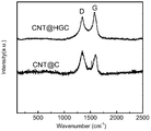
- Figure 2 shows the Raman spectra of CNT@HGC with transition metal containing salt and CNT@C without transition metal containing salt, respectively obtained in Example 1 and Comparative Example 1 of the present invention.
- Figure 3 shows the first three discharge/charge curves at C/10 of S/ (CNT@HGC) (sulfur content 65wt%) (a) and S/ (CNT@C) (b) ; cycling comparison of S/ (CNT@HGC) and S/ (CNT@C) cycled at C/10 for 200 cycles (c) ; and the rate performance of S/ (CNT@HGC) cathode and S/ (CNT@C) cathode at rate of 0.1C, 0.2C, 0.4C, 1C, 2C and 5C obtained in Example 1 and Comparative Example 1 of the present invention.
- Figure 4 is a Transmission Electron Microscopy (TEM) image of GN@Fe x O y @C (before pyrolysis) (a) ; GN@Fe x O y @HGC (after pyrolysis, but before acid etching of Fe x O y nanoparticles) (b) ; GN@HGC (after acid etching of Fe x O y nanoparticles) (c) ; and S/ (GN@HGC) (d) obtained in Example 2 of the present invention.
- TEM Transmission Electron Microscopy
- Figure 5 shows the Raman spectra of GN@HGC with transition metal containing salt, and GN@C without transition metal containing salt, respectively obtained in Example 2 and Comparative Example 2 of the present invention.
- Figure 6 shows the first three discharge/charge curves at C/10 of S/ (GN@HGC) (sulfur content 65wt%) (a) and S/ (GN@C) (b) ; cycling comparison of S/ (GN@HGC) and S/ (GN@C) cycled at C/10 for 200 cycles (c) ; and the rate performance of S/ (GN@HGC) cathode and S/ (GN@C) cathode at rate of 0.1C, 0.2C, 0.5C, 1C, 2C and 5C obtained in Example 2 and Comparative Example 2 of the present invention.
- Figure 7 shows the TEM images of MPCS precursors (a) ; MPCS@Fe x O y composite (before pyrolysis) (b) ; HGCS obtained from MPCS (c) , and HGCS-S (d) obtained in Example 3 of the present invention.
- Figure 8 shows the Raman spectra of HGCS obtained from MPCS, and MPCS respectively obtained in Example 3 and Comparative Example 3 of the present invention.
- Figure 9 shows the first three discharge/charge curves at C/10 of HGCS-S (sulfur content 65wt%) (a) and MPCS-S (b) ; cycling comparison of HGCS-S and MPCS-S cycled at C/10 for 200 cycles (c) ; and the rate performance of HGCS-S cathode and MPCS-S cathode at rate of 0.1C, 0.2C, 0.5C, 1C, and 2C obtained in Example 3 and Comparative Example 3 of the present invention.
- the present invention relates to novel sulfur-carbon cathode composite, as well as their structural design, and corresponding preparation method.
- the present invention also provides lithium-sulfur batteries assembled from said cathode composite.
- the battery testing system and the electrolytes employed are also described.
- a sulfur-carbon composite comprising a highly graphitic carbon material and sulfur
- the highly graphitic carbon material is a graphitic microporous carbon substrate
- the graphitization degree of the highly graphitic carbon material is characterized by a ratio of the intensity of G band to the intensity of D band in Raman spectrum being more than 1.0
- sulfur is encapsulated into the porous structure of the highly graphitic carbon material.
- the graphitic microporous carbon substrate prior to graphitization can be selected from the group consisting of carbon spheres, carbon nanosheets, carbon fibers, carbon nanotubes, carbon molecular sieve, and zeolite-templated carbon, and combinations, composites, derivatives and doped system thereof.
- a sulfur-carbon composite comprising a highly graphitic carbon material and sulfur
- the highly graphitic carbon material is a core-shell material with a conductive core coated by a graphitic microporous carbon layer
- the graphitization degree of the highly graphitic carbon material is characterized by a ratio of the intensity of G band to the intensity of D band in Raman spectrum being more than 1.0
- sulfur is encapsulated into the porous structure of the highly graphitic carbon material.
- the conductive core can be selected from the group consisting of carbon-based material, non-carbon material, and a combination or composite of carbon-based material and non-carbon material.
- any commonly used carbon-based material in the art can be applied in the present invention and the non-limiting examples include one or more selected from the group consisting of amorphous carbon, graphitized carbon, hard carbon, soft carbon, activated carbon, carbon aerogels, carbon nanotubes, expanded graphite, graphene oxide nanosheets, graphene nanosheets, carbide-derived carbon and zeolite-templated carbon, carbon molecular sieve and combinations, composites, derivatives and doped system thereof.
- the carbon-based material is carbon nanotubes or graphene nanosheets.
- the “doped system” in the context of the present invention means that the system can be doped with any suitable heteroatoms or combinations of them, such as N, P, B and so on.
- any commonly used non-carbon material in the art can be applied in the present invention and the non-limiting examples include one or more selected from the group consisting of conductive polymers, semi-conductive ceramic, metal-organic frameworks (MOFs) , non-carbon molecular sieves and combinations, composites, derivatives thereof.
- conductive polymers semi-conductive ceramic, metal-organic frameworks (MOFs) , non-carbon molecular sieves and combinations, composites, derivatives thereof.
- MOFs metal-organic frameworks
- the highly graphitic carbon material has a porous structure with pore diameter being 0.4 nm-100 nm, preferably 0.4-50 nm.
- the highly graphitic carbon material has a BET specific surface area ranging from 100-4500 m 2 /g, preferably from 500-1500 m 2 /g.
- the highly graphitic carbon material has a pore volume of 0.1-3.0 cm 3 /g, preferably 0.3-1.5 cm 3 /g.
- the sulfur-carbon composite has sulfur content of 20-90 wt%, preferably 50-85 wt%based on the total weight of the sulfur-carbon composite.
- the highly graphitic carbon material is carbon nanotube coated by a graphitic microporous carbon layer.
- Fe x O y nanoparticles (briefed as Fe x O y NPs) (NP stands for nanoparticles) grow on the surface of carbon and the thickness of the coating layer outside the CNT before pyrolysis is about 20 nm.
- Figure 1b after pyrolysis at 800°C, lots of graphitic domains can be clearly observed.
- the Fe x O y NPs got completely removed to yield CNT@HGC as shown in Figure 1c.
- no bulk sulfur particles can be observed in the CNT@HGC-S composite, implying the good dispersion of sulfur within the highly graphitic carbon layer, as shown in Figure 1d.
- the Raman spectra of CNT@HGC substrate in Figure 2 exhibits a greatly sharpened G band compared to CNT@C (the carbon layer outside the CNT is not graphitized) , confirming the enhanced graphitization degree.
- the mean I G /I D ratios of CNT@HGC (1.04) were larger than that of CNT@C (0.63) , demonstrating the increased graphitic degree of CNT@HGC.
- the highly graphitic carbon material is graphene nanosheet coated by a graphitic carbon layer.
- the thickness of the amorphous carbon layer outside the graphene nanosheet is about 20 nm.
- GN@HGC was yield as shown in Figure 4b.
- the highly-resolution TEM image as shown in Figure 4c gives an evident observation of the activated graphitic domains.
- no bulk sulfur particle can be observed from the GN@HGC-S composite as shown in Figure 4d, implying the good dispersion of sulfur within the highly graphitic carbon layer.
- GN@C substrate is prepared without Fe x O y NPs, which possesses a low degree of graphitization.
- a clear Raman band at 1343 and 1574 cm -1 corresponds to D and G bands of carbon respectively.
- GN@C substrate only exhibits the conventional D band and G band at 1339 and 1596 cm -1 respectively.
- the obviously sharpened G band shows an increase of the ordered graphitic domains in GN@HGC.
- the mean I G /I D ratios of GN@HGC (1.23) were larger than that of GN@C (0.82) , reaffirming the increased graphitic degree of GN@HGC.
- the highly graphitic carbon material is graphitic microporous carbon spheres.
- the spherical structure of MPCS has a particle size of about 200 nm.
- HGCS highly graphitic carbon spheres
- Fe x O y NPs embedded inside, as shown in Figure 7b.
- these Fe x O y NPs can be completely removed through acid etching process.
- no bulk sulfur particles can be observed from the S/HGCS composite, as shown in Figure 7c, implying the good dispersion of sulfur within the highly graphitic carbon substrate.
- MPCS substrate without Fe x O y NPs is prepared, possessing a low degree of graphitization.
- Raman spectra in Figure 8 exhibits the significantly decreased I G /I D (0.74) for MPCS substrate compared to HGCS (1.28) , exhibiting the distinct improvement of the graphitization degree of HGCS.
- the present invention further relates to an electrode, which comprises the sulfur-carbon composite according to the present invention.
- the present invention further relates to a lithium-sulfur battery, which comprises the sulfur-carbon composite according to the present invention.
- a process for preparing the above sulfur-carbon composite wherein the highly graphitic carbon material is a conductive core coated by a graphitic microporous carbon layer, said process comprises the steps of: mixing an aqueous solution of the conductive core with an aqueous solution of transition metal-containing salt, keeping at 60-120°C for 2-12 h to obtain the conductive core coated by transition metal oxide layer; then carrying out a hydrothermal reaction (for example, in an sealed autoclave at 150-200°C for 5h-20h) by adding carbon source to the above resulting material, followed by centrifuging, washing and drying; pyrolyzing the above obtained material at a temperature of 500-900°C for 1-12 h; removing the transition metal oxide by an acid solution; and loading of sulfur.
- a hydrothermal reaction for example, in an sealed autoclave at 150-200°C for 5h-20h
- the above process may be carried out by the following steps of: mixing an aqueous solution of the conductive core with an aqueous solution of transition metal-containing salt and carbon source at the same time; then carrying out a hydrothermal reaction (for example, in an sealed autoclave at 150-200°C for 5h-20h) , followed by centrifuging, washing and drying; pyrolyzing the above obtained material at a temperature of 500-900°C for 1-12 h; removing the transition metal oxide by an acid solution; and loading of sulfur.
- a hydrothermal reaction for example, in an sealed autoclave at 150-200°C for 5h-20h
- pyrolyzing the above obtained material at a temperature of 500-900°C for 1-12 h
- removing the transition metal oxide by an acid solution and loading of sulfur.
- a hydrothermal reaction intends to mean that during the reaction in aqueous solutions occurred at high vapor pressures and high temperature, a carbonaceous layer is formed on a MO coated substrate materials, or during the reaction, both a MO layer and a carbonaceous layer are formed simultaneously on the core materials.
- a process for preparing the above sulfur-carbon composite wherein the highly graphitic carbon material is a graphitic microporous carbon substrate, said process comprises the steps of: dispersing a microporous carbon substrate in an aqueous solution of transition metal-containing salt, stirring and heating at 60-120°C for 2-12 h; pyrolyzing the obtained material at a temperature of 500-900°C for 1-12 h to carbonize and graphitize the microporous carbon substrate; removing the transition metal oxide by an acid solution, and loading of sulfur.
- said carbon source is one or more selected from the group consisting of sucrose, D-glucose, fructose, polyaniline, polyacetylene, polythiophene, dopamine and sodium alginate.
- the transition metal-containing salt is selected from the group consisting of chloride, sulfate, nitrate, acetate, carbonate and phosphate of Fe, Co and Ni.
- the carbon source is for example sucrose
- the transition metal-containing salt is Fe-containing salt
- the molar ratio of Fe-containing salt to sucrose is preferably ranging from 0.2 to 2.5.
- the microporous carbon substrate is microporous carbon spheres
- the transition metal-containing salt is FeSO 4
- the weight ratio of FeSO 4 to microporous carbon spheres is preferably ranging from 0.2 to 10.
- the step of loading of sulfur comprises dissolving elemental sulfur, which is nonpolar, in one nonpolar solvent for example, dimethyl sulfoxide (DMSO) or dimethylformamide (DMF) with intense ultrasonication.
- DMSO dimethyl sulfoxide
- DMF dimethylformamide
- the ratios of sulfur in the mixture can be adjusted from 50%to 80%.
- the HGC substrate was dispersed in the sulfur/DMSO (for example) solution by ultrasonication.
- another polar solvent deionized water or ethonal for example
- the highly graphitic carbon substrate according to the present invention has favorable electric conductivity, thus is very promising in use as the substrate material for sulfur to form the sulfur-carbon composite for Li-S battery. Moreover, the preparation process is simple to implement, and all raw materials are low in price, all these merits make the composite very promising for Li-S batteries.
- Potential applications of the composite according to the present invention include highly-energy-density lithium ion batteries with acceptable highly power density for energy storage applications, such as power tools, photovoltaic cells and electric vehicles.
- Method 1 Firstly, commercial CNT was pretreated with nitric acid to grow more oxygen-containing functional groups. 200 mL of CNT (0.50 mg/mL) was ultrasonicated for 50 min to form a homogeneous suspension. Fe x O y nanoparticles (Fe x O y NPs) were grown via the in situ hydrolysis of Fe-containing salts on the pretreated CNTs. Typically, for the synthesis of CNTs@Fe x O y , 48 mg of FeCl 3 and 760 mg of FeCl 2 were first dissolved in 100 mL of H 2 O and then added to 160 mL of CNT suspension (0.50 mg/mL) and kept at 90°C for 4h.
- the dried precursor was calcined under argon at 800°C for 3 h, with a heating rate of 3°C/min and a flow rate of 50 mL min -1 .
- the composite was stirred in HCl solution at room temperature for 48 h to obtain the CNT@HGC.
- Method 2 Firstly, commercial CNT was pretreated with nitric acid to grow more oxygen-containing functional groups. Then 100 mg of as-prepared CNTs, 1 g of sucrose, and 500 mg of ferric nitrate were added into 40 mL of water, and sonicated for 1 h, to form a homogenous black suspension. The suspension was then sealed in a 70mL Parr autoclave with a quartz linear and was heated at 180°C for 15 h to yield a dark brown precursor. After the hydrothermal reaction, a uniform carbon precursor layer was formed on the CNT with Fe x O y nanoparticles embedded inside. The precursor was collected by centrifugation, washed with de-ionized water for four times, and then dried at 60°C overnight.
- the dried precursor was calcined under argon at 800°C for 3 h, with a heating rate of 3°C/min and a flow rate of 50 mL min -1 .
- the composite was stirred in HCl solution at room temperature for 48 h to obtain the CNT@HGC.
- Electrochemical measurements were performed with coin cells assembled in an argon-filled glovebox.
- a mixture of active material, carbon black, and poly- (vinyl difluoride) (PVDF) at a weight ratio of 80: 10: 10 was pasted on a Al foil.
- Lithium foil was used as the counter electrode.
- a glass fiber (GF/D) from Whatman was used as a separator.
- the electrolyte consisted of a solution of 1 M LiTFSI salt in a mixture of DOL and DME (1: 1, v/v) (1: 1 in wt %) (Zhangjiagang Guotai Huarong New Chemical Materials Co., Ltd. ) .
- Galvanostatic cycling of the assembled cells was carried out using a battery testing system in the voltage range of 1-3 V (vs Li + /Li) .
- Example 1 The steps in Example 1 were repeated in Comparative Example 1 except that no transition metal-containing salt was added and the carbon source added was not graphitized.
- the obtained CNT@HGC-S cathode composite exhibits discharge capacity of 1260 mAh/g at C/10, and retains at 892 mAh/g after 200 cycles. Moreover, it shows an excellent rate performance.
- the CNT@HGC-S cathode composite still achieves capacities of 926 mAh/g and 696 mAh/g. The specific capacity is calculated based on the mass of S.
- Method 1 Firstly, GO (graphene oxide) was pretreated through Hummer’s method. Then 200 mL of GO solution (0.50 mg/mL) was ultrasonicated for 50 min to form a homogeneous suspension. Fe x O y nanoparticles (Fe x O y NPs) was grown via the in situ hydrolysis of Fe-containing salts on the pretreated GO. Typically, for the synthesis of GO@Fe x O y , 48 mg of FeCl 3 and 760 mg of FeCl 2 were first dissolved in 100 mL of H 2 O and then added to 160 mL of GO suspension (0.50 mg/mL) and kept at 90°C for 4h.
- the dried precursor was calcined under argon at 800°C for 3 h, with a heating rate of 3°C/min and a flow rate of 50 mL min -1 .
- the composite was stirred in HCl solution at room temperature for 48 h to obtain the GO@HGC.
- Method 2 Firstly, GO (graphene oxide) was pretreated through Hummer’s method. Then 100 mg of as-prepared GO, 1 g of sucrose, and 500 mg of ferric nitrate were added into 40 mL of water, and sonicated for 1 h, to form a homogenous black suspension. The suspension was then sealed in a 70mL Parr autoclave with a quartz linear and was heated at 180°C for 15 h to yield a dark brown precursor. After the hydrothermal reaction, a uniform carbon precursor layer was formed on the CNTs with Fe x O y nanoparticles embedded inside. The precursor was collected by centrifugation, washed with de-ionized water for four times, and then dried at 60°C overnight.
- GO graphene oxide
- the dried precursor was calcined under argon at 800°C for 3 h, with a heating rate of 3°C/min and a flow rate of 50 mL min -1 .
- the composite was stirred in HCl solution at room temperature for 48 h to obtain the GO@HGC.
- Example 2 The steps in Example 2 were repeated in Comparative Example 2 except that no transition metal-containing salt was added and the carbon source added was not graphitized.
- the obtained GN@HGC-S cathode composite exhibits discharge capacity of 1375 mAh/g at C/10, and retains at 943 mAh/g after 200 cycles. Moreover, the GN@HGC-S cathode composite shows an excellent rate performance compared to GN@C-S in Comparative Example 2. When increasing the current rates to 1C and 5C, the GN@HGC-S cathode composite still achieves capacities of 900 mAh/g and 765 mAh/g in the initial cycle. However, for the GN@C-S cathode composite, the capacity decreased drastically with less than 300 mAh/g at 2C, implying its slow kinetics property.
- HGCS precursor in which 4.5 g of D-glucose was dissolved in 30 mL of water, the solution was then sealed in an autoclave and reacted at 180°C for 4 h to yield the MPCS.
- the products were centrifuged and washed with water and ethanol for several times before being further dried at 50°C in an oven.
- 50 mg of as-obtained MPCS was dispersed in 20 mL of aqueous solution of ferric sulfate (FeSO 4 ) of 100 mg. The suspension then experienced a vigorous stirring of 2 h, and then heated to 90°C for 1 h to gradually vaporize solvent.
- FeSO 4 ferric sulfate
- the obtained mixture was further dried at 50°C in an oven and then annealed at 800°C in an inert gas (such as nitrogen, argon, etc. ) for 2 h to 4 h with a heating rate of 5°C/min to carbonize and graphitize the MPCS.
- an inert gas such as nitrogen, argon, etc.
- Example 3 The steps in Example 3 were repeated in Comparative Example 3 except that no transition metal-containing salt was added and MPCS was not graphitized.
- the obtained HGCS-S cathode composite exhibits discharge capacity of 1325 mAh/g at C/10, and retains at 861 mAh/g after 200 cycles. Moreover, the HGCS-S cathode composite shows an excellent rate performance. When increasing the current rates to 1C and 2C, the HGCS-S cathode composite still achieves capacities of 845 mAh/g and 770 mAh/g in the initial cycle.
Landscapes
- Chemical & Material Sciences (AREA)
- Organic Chemistry (AREA)
- Chemical Kinetics & Catalysis (AREA)
- Electrochemistry (AREA)
- General Chemical & Material Sciences (AREA)
- Engineering & Computer Science (AREA)
- Materials Engineering (AREA)
- Inorganic Chemistry (AREA)
- Composite Materials (AREA)
- Nanotechnology (AREA)
- Manufacturing & Machinery (AREA)
- Life Sciences & Earth Sciences (AREA)
- General Life Sciences & Earth Sciences (AREA)
- Geology (AREA)
- Battery Electrode And Active Subsutance (AREA)
- Carbon And Carbon Compounds (AREA)
Priority Applications (6)
| Application Number | Priority Date | Filing Date | Title |
|---|---|---|---|
| CN201580084451.0A CN108352514A (zh) | 2015-11-13 | 2015-11-13 | 用于锂-硫电池的含有高石墨化的碳材料的硫-碳复合材料及其制备方法 |
| EP15908106.6A EP3377444A4 (en) | 2015-11-13 | 2015-11-13 | SULFUR-CARBON COMPOUND WITH HIGHLY GRAPHITE CARBON MATERIAL FOR LITHIUM SULFUR BATTERIES AND METHOD FOR THE PRODUCTION THEREOF |
| PCT/CN2015/094586 WO2017079976A1 (en) | 2015-11-13 | 2015-11-13 | Sulfur-carbon composite comprising a highly graphitic carbon material for lithium-sulfur batteries and process for preparing the same |
| KR1020187016484A KR20180080316A (ko) | 2015-11-13 | 2015-11-13 | 리튬-황 배터리용 고 흑연성 탄소 물질을 포함하는 황-탄소 복합물 및 그의 제조 방법 |
| US15/771,498 US10586979B2 (en) | 2015-11-13 | 2015-11-13 | Sulfur-carbon composite comprising a highly graphitic carbon material for lithium-sulfur batteries and process for preparing the same |
| JP2018524341A JP6726279B2 (ja) | 2015-11-13 | 2015-11-13 | リチウム−硫黄電池のための高グラファイト質カーボン材料を含む硫黄−カーボン複合体およびその作製プロセス |
Applications Claiming Priority (1)
| Application Number | Priority Date | Filing Date | Title |
|---|---|---|---|
| PCT/CN2015/094586 WO2017079976A1 (en) | 2015-11-13 | 2015-11-13 | Sulfur-carbon composite comprising a highly graphitic carbon material for lithium-sulfur batteries and process for preparing the same |
Publications (1)
| Publication Number | Publication Date |
|---|---|
| WO2017079976A1 true WO2017079976A1 (en) | 2017-05-18 |
Family
ID=58694636
Family Applications (1)
| Application Number | Title | Priority Date | Filing Date |
|---|---|---|---|
| PCT/CN2015/094586 Ceased WO2017079976A1 (en) | 2015-11-13 | 2015-11-13 | Sulfur-carbon composite comprising a highly graphitic carbon material for lithium-sulfur batteries and process for preparing the same |
Country Status (6)
| Country | Link |
|---|---|
| US (1) | US10586979B2 (enExample) |
| EP (1) | EP3377444A4 (enExample) |
| JP (1) | JP6726279B2 (enExample) |
| KR (1) | KR20180080316A (enExample) |
| CN (1) | CN108352514A (enExample) |
| WO (1) | WO2017079976A1 (enExample) |
Cited By (16)
| Publication number | Priority date | Publication date | Assignee | Title |
|---|---|---|---|---|
| CN108598390A (zh) * | 2018-03-29 | 2018-09-28 | 武汉新能源研究院有限公司 | 一种锂硫电池用正极材料的制备方法及锂硫电池 |
| CN108751169A (zh) * | 2018-06-08 | 2018-11-06 | 天津大学 | 原位合成三维纳米多孔石墨烯包覆金属氧化物/氢氧化物/硫化物复合材料的制备方法 |
| CN109216691A (zh) * | 2018-11-06 | 2019-01-15 | 桑德集团有限公司 | 一种正极活性材料及其制备方法和锂电池 |
| EP3432388A1 (en) | 2017-07-17 | 2019-01-23 | Acondicionamiento Tarrasense | Cathode for lithium sulfur batteries |
| CN109546107A (zh) * | 2018-11-07 | 2019-03-29 | 河南师范大学 | 一种石墨烯/二维Co-Zn双核金属框架结构复合材料的制备方法 |
| CN109592661A (zh) * | 2018-11-30 | 2019-04-09 | 陕西科技大学 | 一种玉米须制备生物碳的方法 |
| KR20190060262A (ko) * | 2017-11-24 | 2019-06-03 | 주식회사 엘지화학 | 황-탄소 복합체, 그의 제조방법 및 이를 포함하는 리튬 이차전지 |
| CN109850865A (zh) * | 2019-01-29 | 2019-06-07 | 河北省科学院能源研究所 | 一种铁负载的海藻酸钠碳气凝胶的制备方法及其应用 |
| CN110229383A (zh) * | 2019-06-19 | 2019-09-13 | 安徽农业大学 | 基于双胺肟纤维素/海藻酸钠的磁性气凝胶及其制备和应用 |
| CN110604132A (zh) * | 2019-09-26 | 2019-12-24 | 吉林大学 | 空心核-卫星状聚多巴胺载银抗菌纳米胶囊的制备方法 |
| WO2020060084A1 (ko) * | 2018-09-20 | 2020-03-26 | 주식회사 엘지화학 | 황-탄소 복합체, 이의 제조방법, 이를 포함하는 리튬 이차전지용 양극 및 리튬 이차전지 |
| WO2020058404A1 (de) | 2018-09-21 | 2020-03-26 | Technische Universität Bergakademie Freiberg | Linkermolekül und schwefelreiche polymere |
| CN111740091A (zh) * | 2020-07-08 | 2020-10-02 | 中国科学院山西煤炭化学研究所 | 一种锂硫电池正极用碳气凝胶@硫复合材料及其制备方法 |
| CN112204770A (zh) * | 2018-07-03 | 2021-01-08 | 株式会社Lg化学 | 硫碳复合物、其制造方法以及包含所述硫碳复合物的锂硫电池用正极和锂硫电池 |
| US12191477B2 (en) | 2018-09-20 | 2025-01-07 | Lg Energy Solution, Ltd. | Sulfur-carbon composite, preparation method thereof, positive electrode for lithium secondary battery and lithium secondary battery comprising same |
| CN119640303A (zh) * | 2025-02-18 | 2025-03-18 | 南京农业大学 | 一种增强生物炭表面导电性的方法、生物炭负载过渡金属的复合材料与应用 |
Families Citing this family (23)
| Publication number | Priority date | Publication date | Assignee | Title |
|---|---|---|---|---|
| US11515519B2 (en) * | 2017-10-17 | 2022-11-29 | VoltaXplore Inc | Graphene-polymer porous scaffold for stable lithium-sulfur batteries |
| CN108821279B (zh) * | 2018-08-17 | 2020-10-13 | 中国人民解放军国防科技大学 | 一种三维多孔碳的制备方法 |
| KR102690253B1 (ko) * | 2018-11-14 | 2024-07-30 | 주식회사 엘지에너지솔루션 | 열팽창된 환원 그래핀 옥사이드, 이의 제조방법, 이를 포함하는 황-탄소 복합체 및 리튬 이차전지 |
| KR102182065B1 (ko) * | 2018-11-23 | 2020-11-23 | 한국과학기술연구원 | 황 도핑 환원 그래핀 옥사이드, 그 제조방법 및 황 도핑 환원 그래핀 옥사이드를 함유한 폴리이미드 나노복합체 |
| CN109576528B (zh) * | 2018-12-21 | 2020-09-18 | 华北电力大学(保定) | 一种以SiC-CDCs@TiC为增强相的铜基复合材料及其制备方法 |
| KR102651786B1 (ko) | 2019-02-13 | 2024-03-26 | 주식회사 엘지에너지솔루션 | 리튬 이차전지용 양극 활물질 |
| CN109880142A (zh) * | 2019-03-08 | 2019-06-14 | 浙江大学 | 一种透明导电金属有机框架物薄膜的制备方法 |
| AU2020248357A1 (en) | 2019-03-22 | 2021-10-14 | Aspen Aerogels, Inc. | Carbon aerogel-based cathodes for lithium-sulfur batteries |
| CN110404567B (zh) * | 2019-08-27 | 2022-04-22 | 中国人民解放军国防科技大学 | 一种光催化能源转化材料及其制备方法与应用 |
| CN110931752B (zh) * | 2019-12-09 | 2021-05-28 | 华南师范大学 | 一种氮掺杂多孔碳负载金属镍的锂硫电池正极材料及其制备方法与应用 |
| JP7400533B2 (ja) * | 2020-02-26 | 2023-12-19 | 株式会社村田製作所 | 複合炭素材およびその製造方法、電極作製用スラリー、電極塗膜並びにリチウムイオン二次電池 |
| JP7400532B2 (ja) * | 2020-02-26 | 2023-12-19 | 株式会社村田製作所 | 複合炭素材およびその製造方法、リチウムイオン二次電池用負極活物質並びにリチウムイオン二次電池 |
| CN111575087A (zh) * | 2020-06-04 | 2020-08-25 | 青岛理工大学 | 一种超滑水润滑添加剂、超滑水润滑剂及制备方法与应用 |
| CN112331850A (zh) * | 2020-09-24 | 2021-02-05 | 厦门大学 | 一种电池自支撑分级结构材料及其制备方法和应用 |
| KR20220054049A (ko) * | 2020-10-23 | 2022-05-02 | 주식회사 엘지에너지솔루션 | 코어-쉘 구조의 다공성 탄소재, 이의 제조방법, 이를 포함하는 황-탄소 복합체, 및 리튬 이차 전지 |
| CN113130882B (zh) * | 2021-04-12 | 2023-02-10 | 肇庆市华师大光电产业研究院 | 一种钠硫电池正极材料的制备方法 |
| CN115678508B (zh) * | 2021-07-26 | 2025-07-08 | 山西大同大学 | 一种金属碳基化学储热复合材料及其制备方法与应用 |
| WO2023085197A1 (ja) * | 2021-11-15 | 2023-05-19 | 株式会社村田製作所 | 炭素材料、炭素材料を備えた電極、二次電池及び炭素材料を製造する方法 |
| CN116328745B (zh) * | 2021-12-24 | 2024-05-10 | 中国科学院上海硅酸盐研究所 | 一种亲疏水可控的硫化多孔石墨烯材料及其制备方法 |
| CN114622242B (zh) * | 2022-02-15 | 2023-01-06 | 苏州大学 | Ni/NiO纳米异质结多孔石墨碳复合材料及其制备方法与应用 |
| CN116639667B (zh) * | 2023-06-19 | 2025-05-13 | 兰州理工大学 | 一种氮掺杂碳管包裹金属氮化物电极材料的制备方法 |
| CN116936748A (zh) * | 2023-08-30 | 2023-10-24 | 深港产学研基地(北京大学香港科技大学深圳研修院) | 单原子负载多孔碳-纳米氧化铁核壳材料及其制备与应用 |
| CN120527349B (zh) * | 2025-07-28 | 2025-09-26 | 青岛理工大学 | 一种三层同轴结构纤维状硫正极的制备装置、方法及电极 |
Citations (4)
| Publication number | Priority date | Publication date | Assignee | Title |
|---|---|---|---|---|
| CN103958402A (zh) * | 2011-11-29 | 2014-07-30 | 中国科学院化学研究所 | 用于锂硫电池的硫碳复合物、制备所述复合物的方法以及包含所述复合物的电极材料和锂硫电池 |
| CN103959517A (zh) * | 2011-11-29 | 2014-07-30 | 中国科学院化学研究所 | 用于锂硫电池的硫碳复合物、制备所述复合物的方法以及包含所述复合物的电极材料和锂硫电池 |
| CN104272506A (zh) * | 2012-02-16 | 2015-01-07 | 罗伯特·博世有限公司 | 用于锂硫电池的含硫复合物、包含所述复合物的电极材料及锂硫电池 |
| US20150246816A1 (en) * | 2014-02-28 | 2015-09-03 | GM Global Technology Operations LLC | Methods for making hollow carbon materials and active materials for electrodes |
Family Cites Families (6)
| Publication number | Priority date | Publication date | Assignee | Title |
|---|---|---|---|---|
| KR20090015449A (ko) * | 2007-08-08 | 2009-02-12 | 현대자동차주식회사 | 수크로스 탄소 전구체로부터 결정성이 우수한 기공성그래파이트 탄소의 제조방법 |
| AU2009223442B2 (en) * | 2008-03-12 | 2014-01-30 | Toyota Jidosha Kabushiki Kaisha | Sulfur-carbon material |
| US9748572B2 (en) * | 2012-06-18 | 2017-08-29 | Uchicago Argonne, Llc | Ultrasound assisted in-situ formation of carbon/sulfur cathodes |
| CN102969487B (zh) * | 2012-11-23 | 2014-09-03 | 南开大学 | 一种用于锂硫电池正极的碳硫复合材料及其制备方法 |
| CN105047861A (zh) * | 2014-12-31 | 2015-11-11 | 山东玉皇新能源科技有限公司 | 一种硫碳复合材料及其制备方法 |
| CN104733695A (zh) * | 2015-03-27 | 2015-06-24 | 浙江大学 | 一种锂硫电池正极用碳/硫复合材料及制备方法和应用 |
-
2015
- 2015-11-13 KR KR1020187016484A patent/KR20180080316A/ko not_active Withdrawn
- 2015-11-13 CN CN201580084451.0A patent/CN108352514A/zh active Pending
- 2015-11-13 WO PCT/CN2015/094586 patent/WO2017079976A1/en not_active Ceased
- 2015-11-13 EP EP15908106.6A patent/EP3377444A4/en not_active Withdrawn
- 2015-11-13 JP JP2018524341A patent/JP6726279B2/ja not_active Expired - Fee Related
- 2015-11-13 US US15/771,498 patent/US10586979B2/en not_active Expired - Fee Related
Patent Citations (4)
| Publication number | Priority date | Publication date | Assignee | Title |
|---|---|---|---|---|
| CN103958402A (zh) * | 2011-11-29 | 2014-07-30 | 中国科学院化学研究所 | 用于锂硫电池的硫碳复合物、制备所述复合物的方法以及包含所述复合物的电极材料和锂硫电池 |
| CN103959517A (zh) * | 2011-11-29 | 2014-07-30 | 中国科学院化学研究所 | 用于锂硫电池的硫碳复合物、制备所述复合物的方法以及包含所述复合物的电极材料和锂硫电池 |
| CN104272506A (zh) * | 2012-02-16 | 2015-01-07 | 罗伯特·博世有限公司 | 用于锂硫电池的含硫复合物、包含所述复合物的电极材料及锂硫电池 |
| US20150246816A1 (en) * | 2014-02-28 | 2015-09-03 | GM Global Technology Operations LLC | Methods for making hollow carbon materials and active materials for electrodes |
Non-Patent Citations (1)
| Title |
|---|
| See also references of EP3377444A4 * |
Cited By (29)
| Publication number | Priority date | Publication date | Assignee | Title |
|---|---|---|---|---|
| EP3432388A1 (en) | 2017-07-17 | 2019-01-23 | Acondicionamiento Tarrasense | Cathode for lithium sulfur batteries |
| KR20190060262A (ko) * | 2017-11-24 | 2019-06-03 | 주식회사 엘지화학 | 황-탄소 복합체, 그의 제조방법 및 이를 포함하는 리튬 이차전지 |
| CN111066181B (zh) * | 2017-11-24 | 2022-07-19 | 株式会社Lg新能源 | 硫碳复合物、其制造方法和包含所述硫碳复合物的锂二次电池 |
| KR102229453B1 (ko) * | 2017-11-24 | 2021-03-17 | 주식회사 엘지화학 | 황-탄소 복합체, 그의 제조방법 및 이를 포함하는 리튬 이차전지 |
| CN111066181A (zh) * | 2017-11-24 | 2020-04-24 | 株式会社Lg化学 | 硫碳复合物、其制造方法和包含所述硫碳复合物的锂二次电池 |
| WO2019103326A3 (ko) * | 2017-11-24 | 2019-07-18 | 주식회사 엘지화학 | 황-탄소 복합체, 그의 제조방법 및 이를 포함하는 리튬 이차전지 |
| US11695111B2 (en) | 2017-11-24 | 2023-07-04 | Lg Energy Solution, Ltd. | Sulfur-carbon composite, preparation method thereof, and lithium secondary battery comprising same |
| CN108598390A (zh) * | 2018-03-29 | 2018-09-28 | 武汉新能源研究院有限公司 | 一种锂硫电池用正极材料的制备方法及锂硫电池 |
| CN108751169A (zh) * | 2018-06-08 | 2018-11-06 | 天津大学 | 原位合成三维纳米多孔石墨烯包覆金属氧化物/氢氧化物/硫化物复合材料的制备方法 |
| CN108751169B (zh) * | 2018-06-08 | 2021-12-28 | 天津大学 | 原位合成三维纳米多孔石墨烯包覆金属氧化物/氢氧化物/硫化物复合材料的制备方法 |
| EP3783703A4 (en) * | 2018-07-03 | 2021-07-28 | Lg Chem, Ltd. | SULFUR-CARBON COMPOSITE, PROCESS FOR ITS MANUFACTURING AND POSITIVE ELECTRODE FOR LITHIUM-SULFUR BATTERY AND LITHIUM-SULFUR BATTERY WITH IT |
| US12431489B2 (en) | 2018-07-03 | 2025-09-30 | Lg Energy Solution, Ltd. | Sulfur-carbon composite, method for preparing the same, and positive electrode for lithium-sulfur battery and lithium-sulfur battery comprising the same |
| CN112204770A (zh) * | 2018-07-03 | 2021-01-08 | 株式会社Lg化学 | 硫碳复合物、其制造方法以及包含所述硫碳复合物的锂硫电池用正极和锂硫电池 |
| US12191477B2 (en) | 2018-09-20 | 2025-01-07 | Lg Energy Solution, Ltd. | Sulfur-carbon composite, preparation method thereof, positive electrode for lithium secondary battery and lithium secondary battery comprising same |
| WO2020060084A1 (ko) * | 2018-09-20 | 2020-03-26 | 주식회사 엘지화학 | 황-탄소 복합체, 이의 제조방법, 이를 포함하는 리튬 이차전지용 양극 및 리튬 이차전지 |
| WO2020058404A1 (de) | 2018-09-21 | 2020-03-26 | Technische Universität Bergakademie Freiberg | Linkermolekül und schwefelreiche polymere |
| DE102018123332B4 (de) | 2018-09-21 | 2022-01-13 | Technische Universität Bergakademie Freiberg | Schwefelreiche Polymere |
| CN109216691B (zh) * | 2018-11-06 | 2021-08-17 | 桑德新能源技术开发有限公司 | 一种正极活性材料及其制备方法和锂电池 |
| CN109216691A (zh) * | 2018-11-06 | 2019-01-15 | 桑德集团有限公司 | 一种正极活性材料及其制备方法和锂电池 |
| CN109546107A (zh) * | 2018-11-07 | 2019-03-29 | 河南师范大学 | 一种石墨烯/二维Co-Zn双核金属框架结构复合材料的制备方法 |
| CN109546107B (zh) * | 2018-11-07 | 2021-12-24 | 河南师范大学 | 一种石墨烯/二维Co-Zn双核金属框架结构复合材料的制备方法 |
| CN109592661A (zh) * | 2018-11-30 | 2019-04-09 | 陕西科技大学 | 一种玉米须制备生物碳的方法 |
| CN109850865A (zh) * | 2019-01-29 | 2019-06-07 | 河北省科学院能源研究所 | 一种铁负载的海藻酸钠碳气凝胶的制备方法及其应用 |
| CN110229383B (zh) * | 2019-06-19 | 2021-10-22 | 安徽农业大学 | 基于双胺肟纤维素/海藻酸钠的磁性气凝胶及其制备和应用 |
| CN110229383A (zh) * | 2019-06-19 | 2019-09-13 | 安徽农业大学 | 基于双胺肟纤维素/海藻酸钠的磁性气凝胶及其制备和应用 |
| CN110604132B (zh) * | 2019-09-26 | 2021-10-08 | 吉林大学 | 空心核-卫星状聚多巴胺载银抗菌纳米胶囊的制备方法 |
| CN110604132A (zh) * | 2019-09-26 | 2019-12-24 | 吉林大学 | 空心核-卫星状聚多巴胺载银抗菌纳米胶囊的制备方法 |
| CN111740091A (zh) * | 2020-07-08 | 2020-10-02 | 中国科学院山西煤炭化学研究所 | 一种锂硫电池正极用碳气凝胶@硫复合材料及其制备方法 |
| CN119640303A (zh) * | 2025-02-18 | 2025-03-18 | 南京农业大学 | 一种增强生物炭表面导电性的方法、生物炭负载过渡金属的复合材料与应用 |
Also Published As
| Publication number | Publication date |
|---|---|
| JP6726279B2 (ja) | 2020-07-22 |
| CN108352514A (zh) | 2018-07-31 |
| US10586979B2 (en) | 2020-03-10 |
| EP3377444A4 (en) | 2019-04-03 |
| JP2018535915A (ja) | 2018-12-06 |
| KR20180080316A (ko) | 2018-07-11 |
| US20180351166A1 (en) | 2018-12-06 |
| EP3377444A1 (en) | 2018-09-26 |
Similar Documents
| Publication | Publication Date | Title |
|---|---|---|
| US10586979B2 (en) | Sulfur-carbon composite comprising a highly graphitic carbon material for lithium-sulfur batteries and process for preparing the same | |
| Yi et al. | A flexible micro/nanostructured Si microsphere cross-linked by highly-elastic carbon nanotubes toward enhanced lithium ion battery anodes | |
| Xie et al. | Sn@ CNT nanopillars grown perpendicularly on carbon paper: a novel free-standing anode for sodium ion batteries | |
| Li et al. | Graphite-embedded lithium iron phosphate for high-power–energy cathodes | |
| Park et al. | Mesoporous graphitic carbon-TiO2 composite microspheres produced by a pilot-scale spray-drying process as an efficient sulfur host material for Li-S batteries | |
| Qin et al. | A porous C/LiFePO4/multiwalled carbon nanotubes cathode material for Lithium ion batteries | |
| Li et al. | Nanoflake-assembled three-dimensional Na3V2 (PO4) 3/C cathode for high performance sodium ion batteries | |
| Li et al. | Porous nitrogen-doped carbon vegetable-sponges with enhanced lithium storage performance | |
| Wang et al. | Onion-like carbon matrix supported Co 3 O 4 nanocomposites: a highly reversible anode material for lithium ion batteries with excellent cycling stability | |
| Yin et al. | Self-assembly of disordered hard carbon/graphene hybrid for sodium-ion batteries | |
| Jiang et al. | A carbon coated NASICON structure material embedded in porous carbon enabling superior sodium storage performance: NaTi 2 (PO 4) 3 as an example | |
| Li et al. | Sulfur supported by carbon nanotubes and coated with polyaniline: preparation and performance as cathode of lithium-sulfur cell | |
| Ding et al. | Octagonal prism shaped lithium iron phosphate composite particles as positive electrode materials for rechargeable lithium-ion battery | |
| Ding et al. | Sustainable solid-state strategy to hierarchical core-shell structured Fe3O4@ graphene towards a safer and green sodium ion full battery | |
| Yang et al. | Excellent cycling stability and superior rate capability of a graphene–amorphous FePO 4 porous nanowire hybrid as a cathode material for sodium ion batteries | |
| Wang et al. | Carbon encapsulated maricite NaFePO4 nanoparticles as cathode material for sodium-ion batteries | |
| Cong et al. | In situ N-doped carbon nanotubes modified NiS2 hierarchical hollow microspheres for boosting sodium storage performance | |
| Wu et al. | Non-graphitic PPy-based carbon nanotubes anode materials for lithium-ion batteries | |
| Wu et al. | Porous hollow carbon nanospheres embedded with well-dispersed cobalt monoxide nanocrystals as effective polysulfide reservoirs for high-rate and long-cycle lithium–sulfur batteries | |
| Bian et al. | Design and synthesis of three-dimensional NaTi2 (PO4) 3@ CNT microspheres as advanced anode materials for rechargeable sodium-ion batteries | |
| Kong et al. | Enveloping a Si/N-doped carbon composite in a CNT-reinforced fibrous network as flexible anodes for high performance lithium-ion batteries | |
| Liu et al. | 1d mesoporous NaTi2 (PO4) 3/carbon nanofiber: the promising anode material for sodium-ion batteries | |
| Yang et al. | High-performance lithium− sulfur batteries fabricated from a three-dimensional porous reduced graphene oxide/La2O3 microboards/sulfur aerogel | |
| KR20180012948A (ko) | 다공성 그래핀 및 탄소질을 포함하는 복합체 | |
| Gangaraju et al. | In-situ preparation of silk-cocoon derived carbon and LiFePO4 nanocomposite as cathode material for Li-ion battery |
Legal Events
| Date | Code | Title | Description |
|---|---|---|---|
| 121 | Ep: the epo has been informed by wipo that ep was designated in this application |
Ref document number: 15908106 Country of ref document: EP Kind code of ref document: A1 |
|
| WWE | Wipo information: entry into national phase |
Ref document number: 2018524341 Country of ref document: JP |
|
| NENP | Non-entry into the national phase |
Ref country code: DE |
|
| ENP | Entry into the national phase |
Ref document number: 20187016484 Country of ref document: KR Kind code of ref document: A |