WO2017078038A1 - 吸収性物品の製造方法及び吸収性物品の製造装置 - Google Patents
吸収性物品の製造方法及び吸収性物品の製造装置 Download PDFInfo
- Publication number
- WO2017078038A1 WO2017078038A1 PCT/JP2016/082511 JP2016082511W WO2017078038A1 WO 2017078038 A1 WO2017078038 A1 WO 2017078038A1 JP 2016082511 W JP2016082511 W JP 2016082511W WO 2017078038 A1 WO2017078038 A1 WO 2017078038A1
- Authority
- WO
- WIPO (PCT)
- Prior art keywords
- groove
- anvil roll
- absorbent article
- uneven sheet
- shaped uneven
- Prior art date
- Legal status (The legal status is an assumption and is not a legal conclusion. Google has not performed a legal analysis and makes no representation as to the accuracy of the status listed.)
- Ceased
Links
Images




Classifications
-
- A—HUMAN NECESSITIES
- A61—MEDICAL OR VETERINARY SCIENCE; HYGIENE
- A61F—FILTERS IMPLANTABLE INTO BLOOD VESSELS; PROSTHESES; DEVICES PROVIDING PATENCY TO, OR PREVENTING COLLAPSING OF, TUBULAR STRUCTURES OF THE BODY, e.g. STENTS; ORTHOPAEDIC, NURSING OR CONTRACEPTIVE DEVICES; FOMENTATION; TREATMENT OR PROTECTION OF EYES OR EARS; BANDAGES, DRESSINGS OR ABSORBENT PADS; FIRST-AID KITS
- A61F13/00—Bandages or dressings; Absorbent pads
- A61F13/15—Absorbent pads, e.g. sanitary towels, swabs or tampons for external or internal application to the body; Supporting or fastening means therefor; Tampon applicators
-
- A—HUMAN NECESSITIES
- A61—MEDICAL OR VETERINARY SCIENCE; HYGIENE
- A61F—FILTERS IMPLANTABLE INTO BLOOD VESSELS; PROSTHESES; DEVICES PROVIDING PATENCY TO, OR PREVENTING COLLAPSING OF, TUBULAR STRUCTURES OF THE BODY, e.g. STENTS; ORTHOPAEDIC, NURSING OR CONTRACEPTIVE DEVICES; FOMENTATION; TREATMENT OR PROTECTION OF EYES OR EARS; BANDAGES, DRESSINGS OR ABSORBENT PADS; FIRST-AID KITS
- A61F13/00—Bandages or dressings; Absorbent pads
- A61F13/15—Absorbent pads, e.g. sanitary towels, swabs or tampons for external or internal application to the body; Supporting or fastening means therefor; Tampon applicators
- A61F13/56—Supporting or fastening means
Definitions
- the present invention relates to an absorbent article manufacturing method and an absorbent article manufacturing apparatus.
- a landing tape for fixing the diaper at a position corresponding to the waist portion is attached to the back sheet.
- the sanitary napkin is attached to the back sheet with a pressure-sensitive adhesive tape for preventing the sanitary napkin from being worn out.
- Such landing tapes and adhesive tapes are attached to the back sheet using, for example, the intermittent cutting transfer device described in the cited documents 1 and 2.
- Patent Document 1 is an invention relating to an intermittent cutting transfer apparatus previously proposed by the present applicant.
- Patent Document 1 includes an anvil roll that winds and conveys an adhesive sheet, and an opening concave portion having an opening area larger than the opening area of the vertical hole is formed on the opening peripheral edge of the vertical hole for suction of the anvil roll.
- a technique relating to an intermittent cutting transfer device is disclosed. According to the intermittent cutting transfer device described in Patent Document 1, when the adhesive sheet is wound around the anvil roll and conveyed, the absorbent sheet is less likely to wrinkle and the absorbent article can be efficiently manufactured.
- Patent Document 2 discloses an intermittent cutting transfer device in which a first suction area and a second suction area having a suction pressure larger than that of the first suction area are formed on the surface of the anvil roll that conveys the web. ing.
- a groove is formed in the second suction region so that the suction pressure in the second suction region is larger than the suction pressure in the first suction region.
- the present invention is a method for manufacturing an absorbent article, in which a strip-shaped uneven sheet formed by cutting a band-shaped uneven sheet having an uneven structure is intermittently adhered to a conveyed object in the form of a band.
- the said conveyance process uses the cutting device provided with the anvil roll which has a receiving blade in a surrounding surface, and the cutter member which has a cutter which contacts this receiving blade on the surface.
- the anvil roll has a groove having a suction hole on its peripheral surface, and the groove is formed corresponding to the position of the convex portion of the strip-shaped uneven sheet.
- the strip-shaped uneven sheet is sucked and conveyed through the suction holes of the anvil roll.
- this invention is a manufacturing apparatus of the absorbent article which adheres the strip
- seat which has an uneven
- a cutting device including an anvil roll having a receiving blade on the peripheral surface and a cutter member having a cutter in contact with the receiving blade on the surface is provided.
- the anvil roll has a groove having a suction hole on its peripheral surface, and the groove is formed corresponding to the position of the convex portion of the strip-shaped uneven sheet.
- the direction in which the convex portion of the strip-shaped uneven sheet extends and the direction in which the groove of the anvil roll extends are the same direction.
- FIG. 1 is a plan view showing an unfolded disposable diaper manufactured according to an embodiment of the present invention.
- FIG. 2 is a perspective view showing a schematic configuration of a diaper manufacturing apparatus suitably used for carrying out the manufacturing method of one embodiment of the present invention.
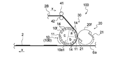
- FIG. 3 is a side view of the manufacturing apparatus shown in FIG.
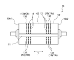
- FIG. 4 is a plan view of the anvil roll provided in the manufacturing apparatus shown in FIG.
- FIG. 5 is an enlarged cross-sectional view of a main part for explaining the relationship between the groove of the anvil roll provided in the manufacturing apparatus shown in FIG. 2 and the convex portion of the concavo-convex sheet being conveyed.
- FIG. 6 is a plan view of another anvil roll provided in a diaper manufacturing apparatus suitably used for carrying out the manufacturing method of one embodiment of the present invention.
- the intermittent cutting transfer device described in Patent Document 1 does not assume the case where the sheet wound around the anvil roll and conveyed is an uneven sheet, and there is room for further improvement when using an uneven sheet. there were.
- the groove formed in the anvil roll described in Patent Document 2 is formed in order to make the suction pressure in the second suction region larger than the suction pressure in the first suction region.
- Patent Document 2 does not describe anything about the relationship between the groove formed on the anvil roll of the intermittent cutting transfer device and the convex portion of the concavo-convex sheet that is wound around the anvil roll and conveyed.
- an object of the present invention is to provide an absorbent article manufacturing method and an absorbent article manufacturing apparatus that can eliminate the disadvantages of the above-described conventional technology.
- the method for producing an absorbent article according to the present invention is such that a strip-like uneven sheet formed by cutting a belt-like uneven sheet having an uneven structure is intermittently pasted on a belt-like sheet as a transported object in the form of a belt. It is a manufacturing method of the absorbent article to wear. Hereinafter, the manufacturing method of this invention is demonstrated, referring drawings based on the preferable embodiment.
- the absorbent article manufactured by the manufacturing method of the present invention is, for example, an unfolded disposable diaper 1 shown in FIG. 1 (hereinafter also referred to as “diaper 1”).
- the elastic waist panel 2 corresponds to the said strip-shaped uneven sheet
- the surface sheet 6a corresponds to the said sheet
- the diaper 1 includes a ventral side A located on the abdomen side of the wearer at the time of wearing, a dorsal side B positioned on the dorsal side, and between the ventral side A and the back side B. It has the absorptive main body 6 which has the crotch part C located, and a pair of left and right waist panels 2 and 2 which are connected to the left and right outer sides of the back side part B.
- the absorptive main body 6 of the diaper 1 has a rectangular shape in a state where the absorbent main body 6 is expanded in a planar shape.
- the longitudinal direction of the absorbent main body 6 (also the longitudinal direction of the diaper 1) is described as the X direction
- the lateral direction of the absorbent main body 6 also the width direction of the diaper 1 is described as the Y direction.
- Each of the pair of waist panels 2 and 2 has a rectangular shape in a state of being expanded in a planar shape.
- Each waist panel 2 includes two sheets 3 and 4 and a plurality of thread-like elastic bodies 5 disposed between the two sheets 3 and 4. As shown in FIG. 1, each waist panel 2 has a thread-like elastic body 5 extending in the lateral direction (Y direction) between two rectangular sheets 3 and 4 having the same shape and the same size. (X direction) are arranged at substantially equal intervals, and are integrally fixed by means such as adhesive or fusion.
- the waist panel 2 formed in this manner is formed with a plurality of ridges to be convex portions 2t extending in the longitudinal direction (X direction) due to the contraction of the thread-like elastic body 5, and has an uneven structure. It becomes. That is, in the waist panel 2, the direction (X direction) in which the convex part 2t extends intersects the direction (Y direction) in which the thread-like elastic body 5 extends. More specifically, in the present embodiment, in the waist panel 2, the extending direction (X direction) of the convex part 2 t and the extending direction (Y direction) of the thread-like elastic body 5 are orthogonal to each other.
- any sheet can be used without particular limitation as long as it is normally used for absorbent articles such as disposable diapers.
- a nonwoven fabric, a woven fabric, a film, or a laminate sheet thereof can be used as the sheets 3 and 4.
- a thread-like elastic body 5 a thread-like stretchable material made of natural rubber, polyurethane, polystyrene-polyisoprene copolymer, polystyrene-polybutadiene copolymer, polyethylene- ⁇ -olefin copolymer such as ethyl acrylate-ethylene, or the like is used. Can be used.
- Fastening tape 7 is fixed to an end of the lateral direction (Y direction) outward side of waist panel 2 which is an uneven sheet by means such as adhesive or fusion.
- the waist panel 2 has an end on the inner side in the lateral direction (Y direction) fixed to the back side B of the back sheet 6b constituting the absorbent main body 6 by means such as adhesive or fusion.
- the side portion B is continuously provided outward in the lateral direction (Y direction).
- the absorbent main body 6 includes a liquid-permeable top sheet 6a, a liquid-impermeable or water-repellent back sheet 6b, and a liquid-retaining property interposed between the two sheets 6a and 6b. And an absorber 6c.
- the absorbent main body 6 includes a top sheet 6a that forms the inner surface of the diaper 1 and a back sheet 6b that forms the outer surface of the diaper 1.
- the absorbent body 6c is interposed between the two sheets 6a and 6b. It is formed by joining.
- the surface sheet 6a and the back sheet 6b constituting the absorbent main body 6 can be used without particular limitation as long as they are usually used for absorbent articles such as disposable diapers.
- a hydrophilic and liquid-permeable non-woven fabric can be used as the top sheet 6a, and a liquid-impermeable or water-repellent resin film or a laminate of a resin film and a non-woven fabric is used as the back sheet 6b.
- the absorbent body 6c an aggregate of fibers such as pulp fibers (may be a non-woven fabric) or an absorbent core in which water-absorbing polymer particles are held therein, a core wrap made of water-permeable thin paper or non-woven fabric. What was covered with the sheet
- FIG. 1 a preferred embodiment of the method for manufacturing an absorbent article according to the present invention will be described with reference to the drawings, taking as an example the case of manufacturing the diaper 1 having the above-described rugged structure waist panel 2.
- 2 and 3 schematically show a manufacturing apparatus 100 that is preferably used in the method for manufacturing the diaper 1.
- the waist panel 2 is connected to the left and right outer sides of the back side portion B of the absorbent main body 6, a pair of left and right manufacturing apparatuses 100 are necessary. Since the manufacturing apparatus 100 has the same configuration, only one manufacturing apparatus 100 is shown in FIG.
- the direction indicated by the symbol x (x direction) indicates the transport direction (MD), and the direction indicated by symbol y (y direction) is a direction orthogonal to the transport direction (x direction).
- a conveyance direction (x direction) is the same direction as the conveyance direction of the continuous body of the diaper 1 which attached the waist panel 2 finally manufactured by this embodiment.
- the manufacturing apparatus 100 includes an anvil roll 10 having a receiving blade 11 on the peripheral surface (surface) 10 f and a cutter having a cutter 21 in contact with the receiving blade 11 on the surface (peripheral surface) 20 f.
- An intermittent cutting transfer device 30 as a cutting device including the member 20 is provided.
- the cutter member 20 is a cutter roll 20 having a cutter 21 on the peripheral surface 20f.
- the anvil roll 10 and the cutter roll 20 rotate in directions opposite to each other.
- the intermittent cutting transfer device 30 is a peripheral surface 10 f of the anvil roll 10 between the anvil roll 10 and the cutter roll 20 that rotate the continuous belt-like uneven sheet 2 ⁇ / b> B having an uneven structure in opposite directions. Then, the anvil roll 10 and the receiving blade 11 provided on the cutter roll 20 are brought into contact with the cutter 21 to intermittently cut the belt-shaped uneven sheet 2B along the y direction.
- the waist panel 2, which is a strip-shaped uneven sheet formed by the cutting, is configured to be transferred and adhered to the belt-shaped surface sheet 6 a constituting the absorbent main body 6 with a predetermined interval.
- the intermittent cutting transfer device 30 it is necessary to intermittently transfer and stick the waist panel 2, which is a concavo-convex sheet, to the belt-like surface sheet 6 a. Therefore, by supplying the belt-like uneven sheet 2B at a speed slower than the rotation speed of the anvil roll 10, the belt-like uneven sheet 2B is slid on the peripheral surface 10f of the anvil roll 10, and the belt-like uneven sheet 2B is cut
- the anvil roll 10 of the intermittent cutting transfer device 30 includes a metal roll body 10B.
- the peripheral surface 10f of the roll body 10B has a groove 13 including a suction hole 12, and the groove 13 is formed corresponding to the position of the convex part 2t of the waist panel 2 which is a strip-shaped uneven sheet.
- the suction hole 12 is provided in the bottom portion 13 b of the groove 13.
- the anvil roll 10 communicates with the lateral holes 14 and a plurality of lateral holes 14 extending in a direction (y direction) orthogonal to one end surface 10 e 1 of the roll body 10 B as shown in FIGS. 2 and 3.
- a plurality of suction holes 12 see FIG.
- a plurality of suction holes 12 are arranged at a predetermined interval in the bottom portion 13 b of the groove 13.
- the receiving blade 11 of the anvil roll 10 is disposed on the peripheral surface 10f so as to extend in the axial direction (y direction) of the roll body 10B, and the cutting edge thereof is more than the peripheral surface 10f. It is fixed to the roll body 10B so as to protrude.
- a pair of receiving blades 11 are arranged at opposite positions of the roll body 10 ⁇ / b> B.
- the groove 13 of the anvil roll 10 is formed in the peripheral surface 10f corresponding to the position of the convex part 2t of the uneven sheet. And the direction where the convex part 2t of an uneven
- the extending direction of the convex part 2t of the uneven sheet is the direction in which the convex part 2t extends with respect to the conveying direction of the uneven sheet
- the extending direction of the groove 13 of the anvil roll 10 is the direction of the groove 13 with respect to the rotational direction of the anvil roll 10. It is an extending direction.
- the groove 13 of the anvil roll 10 extends in the circumferential direction of the anvil roll 10 because the protrusion 2 t extends in the transport direction (x direction) as shown in FIGS. 2 and 4. Is formed.
- a plurality of grooves 13 extending in the circumferential direction of the circumferential surface 10f are arranged at intervals in the axial direction of the roll body 10B.
- the groove 13 of the anvil roll 10 is formed at least in a portion that holds and conveys the waist panel 2 that is a strip-shaped uneven sheet on the peripheral surface 10f of the anvil roll 10 from the viewpoint of stably conveying the formed waist panel 2.
- the manufacturing apparatus 100 only the portion that transports the waist panel 2 as shown in FIGS. It is also formed on the surface of the portion that conveys the belt-shaped uneven sheet 2B, and is formed over the entire circumference of the anvil roll 10 other than the portion where the receiving blade 11 is disposed.
- the groove 13 is on the downstream side in the roll rotation direction with respect to the receiving blade 11 and is formed by cutting.
- the roll body is a normal line at the center of the diameter of the roll body 10B that connects the pair of receiving blades 11 provided at the opposite positions.
- first groove 131 is provided on the downstream side of each receiving blade 11 in the roll rotation direction
- second groove 132 is provided on the upstream side of each receiving blade 11 in the roll rotation direction.
- the depth of the groove of the 1st groove part 131 is formed larger than the depth of the groove of the 2nd groove part 132 from a viewpoint which conveys the strip
- the protrusion 2 t easily enters the groove 13 of the anvil roll 10. Therefore, as shown in FIG. 5, it is preferable that the groove width W1 of the groove 13 of the anvil roll 10 is wider than the width W2 of the belt-shaped uneven sheet 2B and the protrusion 2t of the waist panel 2.
- the width W2 of the convex portion 2t means the length at the widest position in the length of the convex portion 2t in the orthogonal direction (y direction).
- the ratio (W1 / W2) of the groove width W1 of the groove 13 to the width W2 of the convex portion 2t is preferably 1.1 or more, more preferably 2.0 or more, and Preferably, it is 5.0 or less, more preferably 3.0 or less, specifically 1.1 or more and 5.0 or less, and preferably 2.0 or more and 3.0 or less. More preferably.
- the belt-shaped uneven sheet 2B includes two sheets 3 and 4 and a plurality of thread-like elastic bodies 5 disposed between the two sheets 3 and 4, and is convex.
- the protrusion 2t extending in the longitudinal direction (X direction) due to the contraction of the thread-like elastic body 5. Since a plurality of wrinkles are formed, the contraction force of the thread-like elastic body 5 makes it difficult for a gap between the convex portion 2t and the groove 13 that have entered the groove 13 to be generated, increasing the suction force, and the belt-like uneven sheet 2B. And the waist panel 2 can be conveyed more stably.
- the lateral holes 14 of the anvil roll 10 are arranged at a predetermined interval in the circumferential direction of the roll. Each lateral hole 14 is formed in a circular shape. Each lateral hole 14 is formed so as to penetrate from the one end face 10e1 to the other end face 10e2 in parallel with the axial direction of the roll body 10B. Each lateral hole 14 is closed on the other end face 10e2 side by a ring-shaped sealing member (not shown).
- the suction holes 12 of the anvil roll 10 are arranged corresponding to the horizontal holes 14 and extend between the horizontal holes 14 and the grooves 13.
- the suction hole 12 has one end communicating with the lateral hole 14 and the other end disposed on the bottom 13 b of the groove 13. Since the suction holes 12 are arranged in the bottom 13b of the groove 13, in the manufacturing apparatus 100, as shown in FIG. 4, the suction holes 12 are arranged at intervals in the circumferential direction of the anvil roll 10, and the axial direction of the roll main body 10B. Are arranged at intervals.
- Each suction hole 12 is formed in a circular shape.
- a suction ring (not shown) is disposed on one end face 10 e 1 of the anvil roll 10.
- the suction ring (not shown) is fixedly disposed on one end face 10e1 side of a pair of drive shaft support members (not shown) that rotatably support the roll body 10B of the anvil roll 10. That is, the suction ring (not shown) does not rotate with the anvil roll 10. And the suction ring (not shown) is formed in the disk body of the diameter substantially the same as the diameter of the roll main body 10B.
- the suction ring (not shown) has a plurality of mutually independent spatial areas, and the manufacturing apparatus 100 includes three spatial areas a, b, and c as shown in FIG. Have.
- the space area a of the suction ring (not shown) is a band-shaped uneven sheet 2B wound around the peripheral surface 10f of the anvil roll 10 between the receiving blade 11 of the anvil roll 10 and the cutter 21 of the cutter roll 20. It corresponds to the area until supply. Moreover, the space area
- the space area c of the suction ring (not shown) corresponds to the area from the time when the waist panel 2 is adhered to the band-shaped topsheet 6a until the band-shaped uneven sheet 2B is received again in the anvil roll 10.
- An intake fan (not shown) is connected to the suction ring (not shown), and the pressures of the space region a, the space region b, and the space region c that are independent from each other can be adjusted by driving the intake fan.
- the space region a is maintained at a negative pressure
- the space region b is maintained at a negative pressure higher than the space region a
- the space region c is maintained at atmospheric pressure (no pressure).
- Suction air generated by an intake fan leads to a lateral hole 14 formed in the roll body 10B of the anvil roll 10 via a suction ring (not shown).
- the suction air communicates with the suction holes 12 arranged in the bottom portion 13b of the groove 13 formed in the peripheral surface 10f of the roll body 10B through the lateral holes 14. Therefore, in the space area a of the suction ring (not shown), the belt-shaped uneven sheet 2B is moved to the anvil roll 10 by the suction air that leads to the suction holes 12 via the plurality of horizontal holes 14 at positions corresponding to the space area a. The surface 10f is sucked. And in the space area
- the cutter roll 20 of the intermittent cutting transfer device 30 is a metal roll, and is disposed adjacent to the anvil roll 10 so as to sandwich the belt-shaped uneven sheet 2B as shown in FIGS. .
- the cutter roll 20 is provided with a pair of cutters 21 and 21 for contacting the pair of receiving blades 11 and 11 of the anvil roll 10 to cut the strip-shaped uneven sheet 2B.
- the pair of cutters 21 and 21 are disposed at opposing positions of the cutter roll 20, and are fixed so that the cutting edge protrudes from the surface 20f of the roll body 10B.
- the cutter roll 20 is controlled to rotate in a direction opposite to the anvil roll 10 so that the cutters 21 and 21 come into contact with the receiving blades 11 and 11 of the anvil roll 10. That is, while each of the anvil roll 10 and the cutter roll 20 makes one rotation, the cutter roll is arranged such that one cutter 21 comes into contact with one receiving blade 11 and the other cutter 21 comes into contact with the other receiving blade 11. 20 is rotationally controlled with respect to the anvil roll 10.
- the manufacturing apparatus 100 has a pair of drive rolls 41 and 42 that supply the belt-shaped uneven sheet 2 ⁇ / b> B to the anvil roll 10.
- the rotation of the drive rolls 41 and 42 is controlled such that the supply speed of the belt-shaped uneven sheet 2B is slower than the peripheral speed of the anvil roll 10.
- the manufacturing method of the absorbent article of this invention is equipped with the conveyance process which conveys an uneven
- the belt-like uneven sheet 2B and the stretchable waist panel 2 correspond to the uneven sheet
- the belt-like top sheet 6a corresponds to the belt-like sheet (band-like transported object).
- the conveyance process of this embodiment includes an anvil roll 10 having a receiving blade 11 on the peripheral surface 10f, and an intermittent cutting and transferring apparatus including a cutter roll 20 that is a cutter member having a cutter 21 on the surface 20f that contacts the receiving blade 11. 30 is used.
- an intermittent cutting and transferring apparatus including a cutter roll 20 that is a cutter member having a cutter 21 on the surface 20f that contacts the receiving blade 11. 30 is used.
- the original strip-shaped uneven sheet 2B of the stretchable waist panel 2 can be manufactured by the stretchable sheet manufacturing method described in, for example, JP2012-090835A, JP2012-090836A.
- the strip-shaped uneven sheet 2 ⁇ / b> B manufactured by such a manufacturing method has a protrusion 2 t extending in the longitudinal direction (X direction) due to the contraction of the thread-like elastic body 5.
- the adhesive agent is apply
- the suction air fan (not shown) connected to the space area a and the space area b of the suction ring (not shown) of the manufacturing apparatus 100 is operated to make negative pressure.
- Suction air leads to The concavo-convex sheet is sucked into the surface 10 f of the anvil roll 10 by the suction air from the suction hole 12.
- transfer apparatus 30 is provided is rotated in the direction opposite to the rotation direction of the anvil roll 10.
- the belt-like top sheet 6a is directed toward the anvil roll 10 on the downstream side in the roll rotation direction (the portion including the boundary between the space region b and the space region c on the suction ring (not shown)). It is conveyed at the same supply speed as the peripheral speed of the roll 10.
- the strip-shaped uneven sheet 2 ⁇ / b> B is supplied to the peripheral surface 10 f of the anvil roll 10 by the pair of drive rolls 41 and 42.
- the belt-like uneven sheet 2 ⁇ / b> B is supplied to the peripheral surface 10 f of the anvil roll 10 at a supply speed slower than the peripheral speed of the anvil roll 10 by controlling the rotation of the drive rolls 41 and 42.
- the belt-shaped uneven sheet 2B supplied to the peripheral surface 10f of the anvil roll 10 is the surface of the anvil roll 10 by suction air from the suction holes 12 of the grooves 13 at a position corresponding to the space area a of the suction ring (not shown).
- the anvil roll 10 used in the transporting process of the present embodiment has a groove 13 having a suction hole 12 in the bottom portion 13b on the peripheral surface 10f, and the groove 13 corresponds to the position of the convex portion 2t of the concavo-convex sheet 2B. Is formed.
- seat 2B is attracted
- it conveys in the state which made the convex part 2t of the strip
- the belt-like uneven sheet 2B is conveyed in a state where the convex part 2t of the belt-like uneven sheet 2B enters the groove 13 of the anvil roll 10, so that the receiving blade 11 of the anvil roll 10 is used.
- the cutter 21 of the cutter roll 20 can be stably conveyed. Therefore, the diaper 1 can be manufactured stably.
- the belt-shaped uneven sheet 2B has two sheets 3 and 4, and a plurality of thread-like elastic bodies 5 arranged in an extended state between the two sheets 3 and 4, and the protrusion 2t The extending direction and the extending direction of the thread-like elastic body 5 intersect each other.
- a plurality of ridges that are convex portions 2t extending in the vertical direction (X direction) are formed on the belt-shaped uneven sheet 2B in the natural state due to the contraction of the thread-like elastic body 5. Accordingly, when the convex portion 2t of the belt-shaped uneven sheet 2B is conveyed in a state where it enters the groove 13 of the peripheral surface 10f of the anvil roll 10, the convex portion that has entered the groove 13 due to the contraction force of the thread-like elastic body 5. As a result that the gap between 2t and the groove 13 is less likely to occur, the suction force to the belt-like uneven sheet 2B is increased, and the belt-like uneven sheet 2B can be transported more stably.
- corrugated sheet 2B conveyed between the receiving blade 11 of the anvil roll 10 and the cutter 21 of the cutter roll 20 is cut
- a waist panel 2 is formed.
- the belt-shaped uneven sheet 2B is supplied between the anvil roll 10 and the cutter roll 20 and is cut intermittently to be a strip-shaped uneven sheet. Form. That is, since the belt-like uneven sheet 2B is cut on the receiving blade 11, the portion located in front of the receiving blade 11, in other words, the downstream of the anvil roll 10 in the roll rotation direction with respect to the receiving blade 11. The portion sucked and held on the side is formed as a strip-shaped uneven sheet.
- the formed waist panel 2 which is a concavo-convex sheet, is sucked to the surface 10f of the anvil roll 10 by suction air from the suction hole 12 of the groove 13 at a position corresponding to the space region b of the suction ring (not shown). Thus, it is in a state of being wound around the peripheral surface 10f. Then, the waist panel 2 is conveyed to the downstream side in a state of being wound around the surface 10f of the anvil roll 10, and is transferred and adhered to the belt-shaped surface sheet 6a being conveyed with a predetermined interval.
- the anvil roll 10 used in the transporting process of the present embodiment has a groove 13 having a suction hole 12 in the bottom portion 13b on the peripheral surface 10f, and the groove 13 corresponds to the position of the convex portion 2t of the waist panel 2. Is formed.
- the waist panel 2 is attracted
- the convex part 2t of the waist panel 2 is conveyed in a state where it enters the groove 13 of the peripheral surface 10f of the anvil roll 10, the convex part 2t that has entered the groove 13 due to the contraction force of the thread-like elastic body 5 and As a result that the gap with the groove 13 is less likely to occur, the suction force to the waist panel 2 is increased, and the waist panel 2 can be transported more stably. Therefore, the diaper 1 can be manufactured stably.
- the extending direction (x direction) of the convex portions 2t of the belt-shaped uneven sheet 2B that is the uneven sheet and the waist panel 2 that is the uneven sheet, and the extending direction of the groove 13 of the anvil roll 10 are defined.
- the groove 13 of the anvil roll 10 extends in the circumferential direction of the anvil roll 10 and is in the same direction as the direction (x direction) in which the convex portions 2t of the concavo-convex sheet 2B and the waist panel 2 extend. Therefore, as shown in FIG. 5, the convex portion 2t can easily enter the groove 13 of the anvil roll 10, and can be transported more stably, and the diaper 1 can be manufactured more stably.
- the groove 13 of the anvil roll 10 used in the transporting process of the present embodiment has a first groove 131 in a portion that transports the waist panel 2 that is a strip-shaped uneven sheet and is located downstream of the receiving blade 11 in the roll rotation direction. is doing. Therefore, as shown in FIG. 5, the convex portion 2t can easily enter the groove 13 of the anvil roll 10, and can be transported more stably, and the diaper 1 can be manufactured more stably.
- the groove 13 of the anvil roll 10 used in the transporting process of the present embodiment has not only the first groove portion 131 but also the second groove portion 132 having a different groove size on the upstream side in the roll rotation direction of the blade 11. Yes.
- channel 13 of the anvil roll 10 is formed over the perimeter of the anvil roll 10 except the receiving blade 11 part, it is a convex part in the groove
- the suction force of the first groove portion 131 can be made higher than the suction force of the second groove portion 132.
- the belt-like concavo-convex sheet 2 ⁇ / b> B is reliably transported while the peripheral surface of the anvil roll 10 is slid by the second groove 132, and the formed waist panel 2 is surely secured by the first groove 131 on the downstream side of the receiving blade 11. It is held and can be transported more stably.
- the band-shaped topsheet 6a to which the waist panel 2 is attached with an interval is disposed on the strip-shaped topsheet 6a intermittently in the transport direction (x direction).
- a strip-shaped back sheet 6b is disposed on the absorbent body 6c.
- belt-shaped surface sheet 6a are fixed and integrated so that the absorber 6c distribute
- the continuous body of the diaper 1 with which the waist panel 2 was stuck is manufactured.
- a continuous body of diapers 1 can be sequentially manufactured by cutting the diaper 1 into a size of each diaper 1 having one absorbent body 6c by a known cutting means (not shown).
- the manufacturing method of the absorbent article of this invention is not restrict
- the belt-like uneven sheet 2B and the stretchable waist panel 2 correspond to the uneven sheet having the uneven structure
- the belt-like surface sheet 6a is a belt-like sheet (the belt-like sheet) to which the uneven sheet is attached.
- the concavo-convex sheet having the concavo-convex structure is not limited to the belt-shaped concavo-convex sheet 2 ⁇ / b> B and the stretchable waist panel 2.
- belt-shaped surface sheet 6a may be sufficient as the strip
- seat may be sufficient as the strip
- the groove 13 of the anvil roll 10 extends in the circumferential direction of the anvil roll 10, and the belt-like uneven sheet 2 ⁇ / b> B that is an uneven sheet and the waist panel 2 that is an uneven sheet, respectively.
- the convex part 2t extends in the transport direction (x direction), and the direction in which the groove 13 of the anvil roll 10 extends and the direction in which the convex part 2t of the concave and convex sheets 2B and 2 extend (x direction) are the same direction.
- the groove 13 of the anvil roll 10 extends in the axial direction of the anvil roll 10, and the convex portions 2t of the concavo-convex sheets 2B and 2 extend in the direction (y direction) orthogonal to the transport direction (x direction).
- the direction in which the grooves 13 extend and the direction in which the convex portions 2t of the concavo-convex sheets 2B and 2 extend (x direction) may be the same direction.
- the direction in which the groove 13 of the anvil roll 10 extends and the direction in which the convex portions 2t of the concavo-convex sheets 2B and 2 extend (x direction) may not be the same direction.
- the groove 13 is formed in the anvil roll 10 over the whole circumference except for the receiving blade 11 portion, but the groove 13 is as shown in FIG.
- it may have a form having only the first groove 131 formed on the downstream side in the roll rotation direction with respect to the receiving blade 11 and formed in a portion that conveys the waist panel 2 formed by cutting.
- the suction holes 12 are arranged at predetermined intervals over the entire circumference of the anvil roll 10 from the viewpoint of reliably transporting the belt-shaped uneven sheet 2B. That is, as shown in FIG.
- the suction hole 12 is formed at the bottom of the first groove 131 on the downstream side in the roll rotation direction with respect to the receiving blade 11 and in the portion that conveys the waist panel 2 formed by cutting.
- the groove is not formed in the portion that conveys the belt-shaped uneven sheet 2B on the upstream side in the roll rotation direction with respect to the receiving blade 11, and the suction hole 12 is the peripheral surface 10f of the anvil roll. It is preferable that it is arranged above.
- the anvil roll 10 is formed with the groove 13 over the entire circumference except for the receiving blade 11 portion, but the groove 13 is formed in the receiving blade 11 portion. May also be formed. Further, the depth of the first groove 131 on the downstream side of the receiving blade 11 is formed to be larger than the depth of the second groove 132 on the upstream side of the receiving blade 11, but the groove of the first groove 131. And the groove depth of the second groove portion 132 may be the same depth.
- the suction hole 12 is provided in the bottom portion of the groove 13, but the suction hole may be provided in the side wall portion of the groove 13.
- a strip-shaped uneven sheet formed by cutting a band-shaped uneven sheet having an uneven structure is a method for producing an absorbent article that is intermittently adhered to a band-shaped object being conveyed,
- the transporting step uses a cutting device including an anvil roll having a receiving blade on the peripheral surface, and a cutter member having a cutter on the surface that contacts the receiving blade.
- the anvil roll has a groove with a suction hole on its peripheral surface, and the groove is formed corresponding to the position of the convex portion of the strip-shaped uneven sheet,
- the manufacturing method of the absorbent article which attracts
- ⁇ 2> The method for producing an absorbent article according to ⁇ 1>, wherein a direction in which the convex portion of the strip-shaped uneven sheet extends and a direction in which the groove of the anvil roll extends are the same direction.
- channel of the said anvil roll is a manufacturing method of the absorbent article as described in said ⁇ 1> or ⁇ 2> extended in the circumferential direction of this anvil roll.
- the strip-shaped uneven sheet is supplied between the anvil roll and the cutter member, and intermittently cut to form the strip-shaped uneven sheet according to ⁇ 1> to ⁇ 3> The manufacturing method of the absorbent article of any one.
- channel of the said anvil roll is manufactured only in the part which conveys the said strip-shaped uneven
- Method. ⁇ 6> The groove of the anvil roll has a first groove portion formed in a portion that conveys the strip-shaped uneven sheet formed by the cutting, and a portion that conveys the belt-shaped uneven sheet on the peripheral surface of the anvil roll A second groove formed in The method for manufacturing an absorbent article according to ⁇ 4>, wherein the depth of the groove of the first groove is larger than the depth of the groove of the second groove.
- ⁇ 7> The method for manufacturing an absorbent article according to any one of ⁇ 1> to ⁇ 6>, wherein the cutter member is a cutter roll having the cutter on a peripheral surface thereof.
- the cutter member is a cutter roll having the cutter on a peripheral surface thereof.
- ⁇ 9> The method for producing an absorbent article according to any one of ⁇ 1> to ⁇ 8>, wherein the belt-shaped uneven sheet is supplied between the anvil roll and the cutter member at a speed slower than a rotation speed of the anvil roll. .
- ⁇ 10> The method for manufacturing an absorbent article according to any one of ⁇ 1> to ⁇ 9>, wherein a plurality of the suction holes are arranged at a predetermined interval at a bottom portion of the groove of the anvil roll.
- ⁇ 11> The method for manufacturing an absorbent article according to any one of ⁇ 1> to ⁇ 10>, wherein the anvil roll has a plurality of grooves arranged at intervals in the roll axis direction.
- ⁇ 12> The method of manufacturing an absorbent article according to any one of ⁇ 1> to ⁇ 11>, wherein the anvil roll has a plurality of receiving blades arranged on a peripheral surface.
- ⁇ 13> The method for producing an absorbent article according to any one of ⁇ 1> to ⁇ 12>, wherein a groove width W1 of the groove of the anvil roll is wider than a width W2 of the protrusion of the belt-shaped uneven sheet. ⁇ 14> 4.
- the ratio W1 / W2 of the groove width W1 of the groove of the anvil roll to the width W2 of the convex portion of the belt-shaped uneven sheet is 1.1 or more, preferably 2.0 or more, and 0 or less, preferably 3.0 or less, specifically, 1.1 or more and 5.0 or less, preferably 2.0 or more and 3.0 or less.
- Method. ⁇ 15> The method for manufacturing an absorbent article according to any one of ⁇ 1> to ⁇ 14>, wherein the convex portion of the belt-shaped uneven sheet is conveyed in the groove of the anvil roll.
- the strip-shaped uneven sheet has two sheets and a plurality of thread-like elastic bodies arranged between the two sheets, and in a natural state, the contraction of the thread-like elastic bodies causes the uneven sheet of the uneven sheet.
- the band-shaped uneven sheet has two sheets and a plurality of thread-like elastic bodies arranged between the two sheets, and the direction in which the protrusions of the band-shaped uneven sheet extend and the thread shape Intersects the direction in which the elastic body extends,
- the direction in which the convex part of the belt-shaped uneven sheet extends is the same as the direction in which the groove of the anvil roll extends, and the groove width W1 of the groove of the anvil roll is the convex of the belt-shaped uneven sheet.
- a strip-shaped uneven sheet formed by cutting a band-shaped uneven sheet having an uneven structure is an apparatus for manufacturing an absorbent article that intermittently adheres to a band-shaped object being conveyed,
- a cutting device comprising an anvil roll having a receiving blade on the peripheral surface, and a cutter member having a cutter in contact with the receiving blade on the surface;
- the anvil roll has a groove with a suction hole on its peripheral surface, and the groove is formed corresponding to the position of the convex portion of the strip-shaped uneven sheet,
- the manufacturing apparatus of the absorbent article whose extending direction of the said convex part of the said strip-shaped uneven sheet
- channel of the said anvil roll is a manufacturing apparatus of the absorbent article as described in said ⁇ 19> extended in the circumferential direction of this anvil roll.
- channel of the said anvil roll is a manufacturing apparatus of the absorbent article as described in said ⁇ 19> or ⁇ 20> formed only in the said anvil roll rotation direction downstream on the basis of the said receiving blade.
- the groove of the anvil roll has a first groove portion formed on the downstream side in the rotation direction of the anvil roll with reference to the receiving blade, and a second groove portion formed on the upstream side in the rotation direction of the anvil roll,
- the cutter member is a cutter roll having the cutter on a peripheral surface thereof.
- ⁇ 24> The absorbent article manufacturing apparatus according to any one of ⁇ 19> to ⁇ 23>, wherein a plurality of the suction holes are arranged at a predetermined interval at a bottom portion of the groove of the anvil roll.
- ⁇ 25> The absorbent article manufacturing apparatus according to any one of ⁇ 19> to ⁇ 24>, wherein the anvil roll has a plurality of grooves arranged at intervals in the roll axis direction.
- ⁇ 26> The absorbent device manufacturing apparatus according to any one of ⁇ 19> to ⁇ 25>, wherein the anvil roll has a plurality of receiving blades arranged on a peripheral surface thereof.
- ⁇ 27> The apparatus for manufacturing an absorbent article according to any one of ⁇ 19> to ⁇ 26>, wherein a groove width W1 of the groove of the anvil roll is wider than a width W2 of the protrusion of the belt-shaped uneven sheet.
- ⁇ 28> 4 The ratio W1 / W2 of the groove width W1 of the groove of the anvil roll to the width W2 of the convex portion of the belt-shaped uneven sheet is 1.1 or more, preferably 2.0 or more, and 0 or less, preferably 3.0 or less, specifically 1.1 or more and 5.0 or less, preferably 2.0 or more and 3.0 or less, the production of the absorbent article according to the above ⁇ 27>. apparatus.
- the strip-shaped uneven sheet has two sheets and a plurality of thread-like elastic bodies arranged between the two sheets, and in a natural state, the contraction of the thread-like elastic bodies causes the uneven sheet of the uneven sheet.
- the band-shaped uneven sheet has two sheets and a plurality of thread-like elastic bodies arranged between the two sheets, and the direction in which the protrusions of the band-shaped uneven sheet extend and the thread shape Intersects the direction in which the elastic body extends,
- the direction in which the convex part of the belt-shaped uneven sheet extends is the same as the direction in which the groove of the anvil roll extends, and the groove width W1 of the groove of the anvil roll is the convex of the belt-shaped uneven sheet.
- ⁇ 31> The manufacturing apparatus for absorbent articles according to ⁇ 30>, wherein the band-shaped uneven sheet is formed with wrinkles that form the protrusions of the band-shaped uneven sheet by contraction of the thread-like elastic body in a natural state. .
- an uneven sheet can be stably conveyed, and thereby an absorbent article can be produced stably.
Landscapes
- Health & Medical Sciences (AREA)
- Epidemiology (AREA)
- Engineering & Computer Science (AREA)
- Biomedical Technology (AREA)
- Heart & Thoracic Surgery (AREA)
- Vascular Medicine (AREA)
- Life Sciences & Earth Sciences (AREA)
- Animal Behavior & Ethology (AREA)
- General Health & Medical Sciences (AREA)
- Public Health (AREA)
- Veterinary Medicine (AREA)
- Absorbent Articles And Supports Therefor (AREA)
Abstract
本発明の吸収性物品(1)の一例である使い捨ておむつの製造方法は、短冊状の凹凸シートを帯状の被搬送物まで搬送する搬送工程を備える。搬送工程は、受け刃(11)を周面(10f)に有するアンビルロール(10)と、受け刃(11)と接触するカッター(21)を表面(20f)に有するカッター部材(20)とを備えた切断装置を用いる。搬送工程では、アンビルロール(10)の吸引穴(12)を介して短冊状の凹凸シート(2)を吸引して搬送する。
Description
本発明は、吸収性物品の製造方法及び吸収性物品の製造装置に関する。
例えば、おむつには、腰部分に相当する位置に該おむつを固定するためのランディングテープがバックシートに貼着されている。また、生理用ナプキンには、該生理用ナプキンの装着ずれを防止するためのずれ防止用の粘着テープがバックシートに貼着されている。このようなランディングテープや粘着テープは、例えば、引用文献1~引用文献2に記載の間欠切断転写装置を用いてバックシートに貼着されるようになっている。
特許文献1は、本出願人が先に提案した間欠切断転写装置に関する発明である。特許文献1には、貼付シートを巻き付けて搬送するアンビルロールを備え、該アンビルロールの吸引用の縦穴の開口周縁部に、該縦穴の開口面積よりも大きな開口面積を持つ開口凹部を形成している間欠切断転写装置に関する技術が開示されている。特許文献1に記載の間欠切断転写装置によれば、アンビルロールに巻き付けて貼付シートを搬送する際に、貼付シートに皺が発生し難く、吸収性物品を効率的に製造することができる。
また、特許文献2には、ウエブを搬送するアンビルロールの表面に、第1吸引領域と、該第1吸引領域よりも吸引圧力の大きい第2吸引領域とを形成した間欠切断転写装置が開示されている。特許文献2に記載のアンビルロールは、第2吸引領域に溝を形成して、第1吸引領域の吸引圧力よりも第2吸引領域の吸引圧力を大きくしている。
本発明は、凹凸構造を有する帯状の凹凸シートを切断してなる短冊状の凹凸シートを、搬送されている帯状の被搬送物に間欠的に貼着する吸収性物品の製造方法である。前記短冊状の凹凸シートを前記帯状の被搬送物まで搬送する搬送工程を備える。前記搬送工程は、受け刃を周面に有するアンビルロールと、該受け刃と接触するカッターを表面に有するカッター部材とを備えた切断装置を用いる。前記アンビルロールは、その周面に、吸引穴を備える溝を有し、該溝が、前記短冊状の凹凸シートの凸部の位置に対応して形成されている。前記搬送工程においては、前記アンビルロールの前記吸引穴を介して前記短冊状の凹凸シートを吸引して搬送する。
また、本発明は、凹凸構造を有する帯状の凹凸シートを切断してなる短冊状の凹凸シートを、搬送されている帯状の被搬送物に間欠的に貼着する吸収性物品の製造装置である。受け刃を周面に有するアンビルロールと、該受け刃と接触するカッターを表面に有するカッター部材とを備えた切断装置を具備する。前記アンビルロールは、その周面に、吸引穴を備える溝を有し、該溝が、前記短冊状の凹凸シートの凸部の位置に対応して形成されている。前記短冊状の凹凸シートの前記凸部の延びる方向と、前記アンビルロールの前記溝の延びる方向とが同じ方向である。
特許文献1に記載の間欠切断転写装置は、アンビルロールに巻き付けて搬送するシートが凹凸形状のシートである場合を想定しておらず、凹凸形状のシートを用いる場合に、更なる改良の余地があった。
また、特許文献2に記載にアンビルロールに形成された溝は、第1吸引領域の吸引圧力よりも第2吸引領域の吸引圧力を大きくするために形成したものである。特許文献2には、間欠切断転写装置の有するアンビルロールに形成された溝と、アンビルロールに巻き付けて搬送する凹凸形状のシートの凸部との関係に関して、何ら記載されていない。
したがって本発明は、前述した従来技術が有する欠点を解消し得る吸収性物品の製造方法及び吸収性物品の製造装置を提供することにある。
本発明の吸収性物品の製造方法は、凹凸構造を有する帯状の凹凸シートを切断してなる短冊状の凹凸シートを、搬送されている帯状の被搬送物としての帯状のシートに間欠的に貼着する吸収性物品の製造方法である。以下、本発明の製造方法を、その好ましい実施態様に基づき図面を参照しながら説明する。本発明の製造方法で製造される吸収性物品は、例えば、図1に示す展開型の使い捨ておむつ1(以下、「おむつ1」ともいう。)である。そして、おむつ1の製造方法においては、伸縮性のウエストパネル2が前記短冊状の凹凸シートに該当し、表面シート6aがウエストパネル2を貼着する前記シート(被搬送物)に該当する。先ず、製造される伸縮性のウエストパネルを備えた展開型の使い捨ておむつ1について説明する。
おむつ1は、図1に示すように、装着時に装着者の腹側に位置する腹側部A、背側に位置する背側部B、及び腹側部Aと背側部Bとの間に位置する股下部Cを有する吸収性本体6と、背側部Bの左右両外方に連設された左右一対のウエストパネル2,2とを有している。尚、おむつ1の吸収性本体6は、図1に示すように、平面状に拡げた状態において、長方形状である。
以下の説明では、吸収性本体6の縦方向(おむつ1の長手方向でもある)をX方向、吸収性本体6の横方向(おむつ1の幅方向でもある)をY方向として説明する。
以下の説明では、吸収性本体6の縦方向(おむつ1の長手方向でもある)をX方向、吸収性本体6の横方向(おむつ1の幅方向でもある)をY方向として説明する。
一対のウエストパネル2,2それぞれは、平面状に拡げた状態において、矩形状である。各ウエストパネル2は、2枚のシート3,4と、2枚のシート3,4の間に配された複数本の糸状弾性体5とを有している。各ウエストパネル2は、図1に示すように、同形同大の矩形状の2枚のシート3,4の間に、横方向(Y方向)に伸長した糸状弾性体5を、縦方向(X方向)に略等間隔を空けて配して、接着剤や融着等の手段により一体的に固定して形成されている。このように形成されたウエストパネル2は、自然状態において、糸状弾性体5の収縮によって、縦方向(X方向)に延びる凸部2tとなる皺が複数形成されており、凹凸構造を有する凹凸シートとなる。すなわち、ウエストパネル2においては、凸部2tの延びる方向(X方向)と、糸状弾性体5の延びる方向(Y方向)とは交差している。より具体的に、本実施形態においては、ウエストパネル2は、凸部2tの延びる方向(X方向)と、糸状弾性体5の延びる方向(Y方向)とが直交している。
凹凸シートであるウエストパネル2を構成するシート3,4としては、通常、使い捨ておむつ等の吸収性物品に用いられるものであれば、特に制限なく用いることができる。例えば、シート3,4としては、不織布、織物、フィルムまたはそれらの積層シート等を用いることができる。糸状弾性体5としては、天然ゴム、ポリウレタン、ポリスチレン-ポリイソプレン共重合体、ポリスチレン-ポリブタジエン共重合体、アクリル酸エチル-エチレン等のポリエチレン-αオレフィン共重合体等からなる糸状の伸縮性材料を用いることができる。
凹凸シートであるウエストパネル2には、その横方向(Y方向)外方側の端部にファスニングテープ7が接着剤や融着等の手段により固定されている。また、ウエストパネル2は、その横方向(Y方向)内方側の端部が接着剤や融着等の手段により吸収性本体6を構成する裏面シート6bの背側部Bに固定され、背側部Bの横方向(Y方向)外方に連設されている。
吸収性本体6は、図1に示すように、液透過性の表面シート6aと、液不透過性又は撥水性の裏面シート6bと、これら両シート6a,6b間に介在された液保持性の吸収体6cとを有している。吸収性本体6は、図1に示すように、おむつ1の内面をなす表面シート6aと、おむつ1の外面をなす裏面シート6bとを、これら両シート6a,6b間に吸収体6cを介在させて接合することにより形成されている。
吸収性本体6を構成する表面シート6a、裏面シート6bとしては、それぞれ、通常、使い捨ておむつ等の吸収性物品に用いられるものであれば、特に制限なく用いることができる。例えば、表面シート6aとしては、親水性且つ液透過性の不織布等を用いることができ、裏面シート6bとしては、液不透過性又は撥水性の樹脂フィルムや樹脂フィルムと不織布の積層体等を用いることができる。吸収体6cとしては、パルプ繊維等の繊維の集合体(不織布であっても良い)又はこれに吸水性ポリマーの粒子を保持させてなる吸収性コアを、透水性の薄紙や不織布からなるコアラップシートで被覆したもの等を用いることができる。
次に、本発明の吸収性物品の製造方法の好ましい実施態様を、前述した凹凸構造のウエストパネル2を有するおむつ1を製造する場合を例にとり図面を参照しながら説明する。図2及び図3には、おむつ1の製造方法に好適に用いられる製造装置100が模式的に示されている。尚、上述したように、ウエストパネル2は、吸収性本体6の背側部Bの左右両外方に連設されているため、左右一対の2個の製造装置100が必要であるが、各製造装置100は同じ構成であるため、図2には一方の製造装置100のみを示している。
図2及び図3中符合xで示す方向(x方向)は、搬送方向(MD)を示し、符号yで示す方向(y方向)は搬送方向(x方向)に直交する方向である。搬送方向(x方向)は、最終的に本実施態様により製造されるウエストパネル2を取り付けたおむつ1の連続体の搬送方向とも同じ方向である。
製造装置100は、図2及び図3に示すように、受け刃11を周面(表面)10fに有するアンビルロール10と、受け刃11と接触するカッター21を表面(周面)20fに有するカッター部材20とを備えた切断装置としての間欠切断転写装置30を具備している。本実施態様における製造装置100においては、カッター部材20は、カッター21を周面20fに有するカッターロール20である。アンビルロール10とカッターロール20とは、製造装置100では、互いに逆向きに回転するようになっている。
間欠切断転写装置30は、製造装置100では、凹凸構造を有する連続した帯状の凹凸シート2Bを、互いに逆向きに回転するアンビルロール10とカッターロール20との間に、アンビルロール10の周面10fに巻き付けるようにして供給し、これらアンビルロール10とカッターロール20に設けられた受け刃11とカッター21とを接触させて、帯状の凹凸シート2Bをy方向に沿って間欠的に切断する。その切断により形成された短冊状の凹凸シートであるウエストパネル2を、吸収性本体6を構成する帯状の表面シート6aに所定間隔を持って転写して貼着させるように構成したものである。
間欠切断転写装置30では、凹凸シートであるウエストパネル2を帯状の表面シート6aに間欠的に転写して貼着させる必要がある。その為、帯状の凹凸シート2Bをアンビルロール10の回転速度よりも遅い速度で供給することによって、帯状の凹凸シート2Bをアンビルロール10の周面10f上で滑らせるようにして、帯状の凹凸シート2Bを切断し、凹凸シートであるウエストパネル2を形成するようになっている。
間欠切断転写装置30のアンビルロール10は、金属製のロール本体10Bを備えており、図4に示すように、ロール本体10Bの周面10fに、吸引穴12を備える溝13を有し、溝13が、短冊状の凹凸シートであるウエストパネル2の凸部2tの位置に対応して形成されている。本実施形態においては、吸引穴12は溝13の底部13bに設けられている。好適に、アンビルロール10は、製造装置100では、図2及び図3に示すように、ロール本体10Bの一端面10e1から直交する方向(y方向)に延びる複数の横穴14と、横穴14に連通し且つアンビルロール10の周方向に延びる複数の吸引穴12(図4参照)と、周面10fに少なくとも一つの受け刃11とを有している。また、溝13の底部13bには複数の吸引穴12が所定の間隔を空けて配されている。
アンビルロール10の受け刃11は、図2~図4に示すように、ロール本体10Bの軸方向(y方向)に延びるように周面10fに配されており、その刃先が周面10fよりも突出するようにロール本体10Bに固定されている。受け刃11は、製造装置100では、ロール本体10Bの相対向する位置に一対配されている。
アンビルロール10の溝13は、凹凸シートの凸部2tの位置に対応して周面10fに形成されている。そして、凹凸シートの凸部2tの延びる方向と、アンビルロール10の溝13の延びる方向とが同じ方向となっている。ここで、凹凸シートの凸部2tの延びる方向は、凹凸シートの搬送方向に対する凸部2tの延びる方向であり、アンビルロール10の溝13の延びる方向は、アンビルロール10の回転方向に対する溝13の延びる方向である。このように、凸部2tと溝13とが同じ方向に延びていれば、凹凸シートを安定的に搬送することができる。好適に、アンビルロール10の溝13は、製造装置100では、図2及び図4に示すように、凸部2tが搬送方向(x方向)に延びているので、アンビルロール10の周方向に延びて形成されている。このように周面10fの周方向に延びる溝13が、製造装置100では、ロール本体10Bの軸方向に間隔を空けて複数配されている。
アンビルロール10の溝13は、形成されたウエストパネル2を安定的に搬送する観点から、アンビルロール10の周面10fにおける短冊状の凹凸シートであるウエストパネル2を保持、搬送する部分に少なくとも形成されていればよいが、帯状の凹凸シート2B及びウエストパネル2を更に安定的に搬送する観点から、製造装置100では、図2及び図4に示すように、ウエストパネル2を搬送する部分のみならず帯状の凹凸シート2Bを搬送する部分の表面にも形成されており、受け刃11が配設された部分以外のアンビルロール10の全周に亘って形成されている。受け刃11部分を除く全周に亘って溝13が形成されているアンビルロール10では、溝13は、受け刃11を基準としてロール回転方向下流側であって、切断により形成されたウエストパネル2を搬送する部分に形成された第1溝部131と、受け刃11を基準としてロール回転方向上流側であって、帯状の凹凸シート2Bを搬送する部分に形成された第2溝部132とを有している。本実施形態においては、受け刃11が相対向する位置に一対配されているので、相対向する位置に設けられた一対の受け刃11を結ぶロール本体10Bの直径の中心における法線でロール本体10Bを2分割して、各受け刃11のロール回転方向下流側に第1溝部131が設けられ、各受け刃11のロール回転方向上流側に第2溝部132が設けられている。そして、帯状の凹凸シート2B及びウエストパネル2を更に安定的に搬送する観点から、第1溝部131の溝の深さが、第2溝部132の溝の深さよりも大きく形成されている。
帯状の凹凸シート2B及びウエストパネル2を安定的に搬送する為には、アンビルロール10の溝13内に凸部2tが入り込み易いことが好ましい。その為、図5に示すように、アンビルロール10の溝13の溝幅W1が、帯状の凹凸シート2B及びウエストパネル2の凸部2tの幅W2よりも広いことが好ましい。凸部2tの幅W2とは、凸部2tの直交する方向(y方向)の長さの内の最も広い位置での長さを意味する。同様の観点から、凸部2tの幅W2に対する溝13の溝幅W1の比(W1/W2)が、1.1以上であることが好ましく、2.0以上であることが更に好ましく、そして、5.0以下であることが好ましく、3.0以下であることが更に好ましく、具体的には、1.1以上5.0以下であることが好ましく、2.0以上3.0以下であることが更に好ましい。
特に、本実施態様においては、帯状の凹凸シート2Bは、2枚のシート3,4と、2枚のシート3,4の間に配された複数本の糸状弾性体5とを有し、凸部2tの延びる方向と糸状弾性体5の延びる方向とは交差しているので、より具体的には、自然状態において、糸状弾性体5の収縮によって、縦方向(X方向)に延びる凸部2tとなる皺が複数形成されているので、糸状弾性体5の収縮力により、溝13内に入り込んだ凸部2tと溝13との隙間が生じにくくなって吸引力が高まり、帯状の凹凸シート2B及びウエストパネル2をより安定的に搬送することができる。
特に、本実施態様においては、帯状の凹凸シート2Bは、2枚のシート3,4と、2枚のシート3,4の間に配された複数本の糸状弾性体5とを有し、凸部2tの延びる方向と糸状弾性体5の延びる方向とは交差しているので、より具体的には、自然状態において、糸状弾性体5の収縮によって、縦方向(X方向)に延びる凸部2tとなる皺が複数形成されているので、糸状弾性体5の収縮力により、溝13内に入り込んだ凸部2tと溝13との隙間が生じにくくなって吸引力が高まり、帯状の凹凸シート2B及びウエストパネル2をより安定的に搬送することができる。
アンビルロール10の横穴14は、ロールの周方向に所定間隔を空けて配されている。各横穴14は、円形状に形成されている。各横穴14は、ロール本体10Bの軸方向と平行に、一端面10e1から他端面10e2に亘って貫通して形成されている。各横穴14は、他端面10e2側において、リング状をなす封止部材(不図示)によって閉塞されている。
アンビルロール10の吸引穴12は、各横穴14に対応して配され、各横穴14と溝13との間に亘っている。言い換えれば、吸引穴12は、その一端が横穴14に連通していると共に、その他端が溝13の底部13bに配されている。吸引穴12は、溝13の底部13bに配されているので、製造装置100では、図4に示すように、アンビルロール10の周方向に間隔を空けて配され、且つロール本体10Bの軸方向に間隔を空けて配されている。各吸引穴12は、円形状に形成されている。
アンビルロール10の一端面10e1には、サクションリング(不図示)が配されている。サクションリング(不図示)は、アンビルロール10のロール本体10Bを回転可能に支持する一対の駆動軸支持部材(不図示)の内の一端面10e1側に固定して配されている。即ち、サクションリング(不図示)は、アンビルロール10と共には回転しないようになっている。そして、サクションリング(不図示)は、ロール本体10Bの直径とほぼ同一直径の円盤体に形成されている。サクションリング(不図示)は、内部に相互に独立した複数の空間領域を有しており、製造装置100では、図3に示すように、3つの空間領域a、空間領域b及び空間領域cを有している。
アンビルロール10の一端面10e1には、サクションリング(不図示)が配されている。サクションリング(不図示)は、アンビルロール10のロール本体10Bを回転可能に支持する一対の駆動軸支持部材(不図示)の内の一端面10e1側に固定して配されている。即ち、サクションリング(不図示)は、アンビルロール10と共には回転しないようになっている。そして、サクションリング(不図示)は、ロール本体10Bの直径とほぼ同一直径の円盤体に形成されている。サクションリング(不図示)は、内部に相互に独立した複数の空間領域を有しており、製造装置100では、図3に示すように、3つの空間領域a、空間領域b及び空間領域cを有している。
サクションリング(不図示)の空間領域aは、アンビルロール10において、周面10fに巻き付けた状態の帯状の凹凸シート2Bを、アンビルロール10の受け刃11とカッターロール20のカッター21との間に供給するまでの領域に対応している。また、サクションリング(不図示)の空間領域bは、アンビルロール10において、アンビルロール10とカッターロール20とで切断した短冊状の凹凸シートであるウエストパネル2を、帯状の表面シート6aに貼着するまでの領域に対応している。サクションリング(不図示)の空間領域cは、アンビルロール10において、ウエストパネル2を帯状の表面シート6aに貼着してから再度帯状の凹凸シート2Bを受け取るまでの領域に対応している。
サクションリング(不図示)には吸気ファン(不図示)が接続されており、該吸気ファンの駆動により、相互に独立した空間領域a、空間領域b及び空間領域cの圧力が調整できるようになっており、製造装置100においては、空間領域aが負圧に維持され、空間領域bが空間領域aよりも高い負圧に維持され、空間領域cが大気圧(圧力ゼロ)に維持されている。吸気ファン(不図示)によって発生したサクションエアーは、サクションリング(不図示)を介してアンビルロール10のロール本体10Bに形成された横穴14に通じることになる。そしてさらに、上記サクションエアーは、横穴14を介して、ロール本体10Bの周面10fに形成された溝13の底部13bに配されている吸引穴12に通じている。その為、サクションリング(不図示)の空間領域aでは、空間領域aに対応する位置にある複数の横穴14を経由して吸引穴12に通じるサクションエアーによって、帯状の凹凸シート2Bがアンビルロール10の表面10fに吸引させるようになっている。そして、サクションリング(不図示)の空間領域bでは、空間領域bに対応する位置にある複数の横穴14を経由して吸引穴12に通じるサクションエアーによって、ウエストパネル2がアンビルロール10の表面10fに吸引させるようになっている。なお、サクションリング(不図示)はアンビルロール10とは独立して駆動軸支持部材(不図示)に固定されているので、該アンビルロール10が回転したとしても、空間領域a、空間領域b及び空間領域cの位置は変わらず、サクションエアーが通じる範囲は常に一定なものとなっている。
間欠切断転写装置30のカッターロール20は、金属製のロールであり、図2及び図3に示すように、帯状の凹凸シート2Bを挟み込むように、該アンビルロール10に隣接して配置されている。製造装置100では、カッターロール20に、該アンビルロール10の一対の受け刃11,11とそれぞれ接触して帯状の凹凸シート2Bを切断するための一対のカッター21,21が配されている。一対のカッター21,21は、カッターロール20の相対向する位置に配され、刃先がロール本体10Bの表面20fよりも突出するように固定されている。
カッターロール20は、アンビルロール10とは逆向きに回転して、それぞれのカッター21,21が、アンビルロール10の受け刃11,11に対して接触するように回転制御されている。即ち、アンビルロール10及びカッターロール20がそれぞれ一回転する間に、一方の受け刃11に一方のカッター21が接触し、他方の受け刃11に他方のカッター21が接触するように、上記カッターロール20がアンビルロール10に対して回転制御されている。
製造装置100は、アンビルロール10に帯状の凹凸シート2Bを供給する一対の駆動ロール41,42を有している。駆動ロール41,42の回転は、アンビルロール10の周速度よりも帯状の凹凸シート2Bの供給速度が遅くなるように制御されている。
次に、上述した製造装置100を用い、凹凸構造のウエストパネル2を有するおむつ1を製造する方法について説明する。
本発明の吸収性物品の製造方法は、凹凸シートを帯状の被搬送物としての帯状のシートまで搬送する搬送工程を備えている。おむつ1の製造方法においては、帯状の凹凸シート2B及び伸縮性のウエストパネル2が前記凹凸シートに該当し、帯状の表面シート6aが前記帯状のシート(帯状の被搬送物)に該当する。本実施態様の搬送工程は、受け刃11を周面10fに有するアンビルロール10と、受け刃11と接触するカッター21を表面20fに有するカッター部材であるカッターロール20とを備えた間欠切断転写装置30を用いている。
以下、具体的に、製造装置100を用いる本実施態様のおむつ1の製造方法について説明する。
本発明の吸収性物品の製造方法は、凹凸シートを帯状の被搬送物としての帯状のシートまで搬送する搬送工程を備えている。おむつ1の製造方法においては、帯状の凹凸シート2B及び伸縮性のウエストパネル2が前記凹凸シートに該当し、帯状の表面シート6aが前記帯状のシート(帯状の被搬送物)に該当する。本実施態様の搬送工程は、受け刃11を周面10fに有するアンビルロール10と、受け刃11と接触するカッター21を表面20fに有するカッター部材であるカッターロール20とを備えた間欠切断転写装置30を用いている。
以下、具体的に、製造装置100を用いる本実施態様のおむつ1の製造方法について説明する。
伸縮性のウエストパネル2の元の帯状の凹凸シート2Bは、例えば、特開2012-090835号公報、特開2012-090836号公報等に記載の伸縮性シートの製造方法により製造することができる。このような製造方法により製造された帯状の凹凸シート2Bは、糸状弾性体5の収縮によって、縦方向(X方向)に延びる凸部2tを有している。なお、帯状の凹凸シート2Bは、アンビルロール10の周面10fに巻き付く前の段階で、帯状の裏面シート6bに貼着する部分に接着剤が塗布されている。
先ず、製造装置100のサクションリング(不図示)の空間領域a及び空間領域b内を、接続された吸気ファン(不図示)を作動させて負圧にする。サクションリング(不図示)の空間領域a及び空間領域b内を負圧にすることで、空間領域a及び空間領域bに対応する位置にある複数の横穴14を経由して溝13の吸引穴12にサクションエアーが通じる。吸引穴12からのサクションエアーによって、凹凸シートがアンビルロール10の表面10fに吸引するようになる。そして、間欠切断転写装置30の備えるアンビルロール10を回転させると共に、間欠切断転写装置30の備えるカッターロール20をアンビルロール10の回転方向とは逆向きに回転させる。
また、本実施態様では、帯状の表面シート6aを、アンビルロール10のロール回転方向下流側(サクションリング(不図示)の空間領域bと空間領域cとの境界を含む部分)に向かって、アンビルロール10の周速度と同じ供給速度で搬送する。
次いで、一対の駆動ロール41,42によってアンビルロール10の周面10fに帯状の凹凸シート2Bが供給される。ここで、駆動ロール41,42の回転の制御により、アンビルロール10の周速度よりも遅い供給速度で、帯状の凹凸シート2Bがアンビルロール10の周面10fに供給される。
アンビルロール10の周面10fに供給された帯状の凹凸シート2Bは、サクションリング(不図示)の空間領域aに対応する位置にて溝13の吸引穴12からのサクションエアーによってアンビルロール10の表面10fに吸引されて、周面10fに巻き付いた状態となる。そして、帯状の凹凸シート2Bは、アンビルロール10の表面10fに巻き付いた状態で、アンビルロール10の受け刃11とカッターロール20のカッター21との間に搬送される。上述のように、帯状の凹凸シート2Bの供給速度は、アンビルロール10の周速度よりも遅いので、帯状の凹凸シート2Bはアンビルロール10の周面を滑りながら受け刃11とカッター21との間に搬送されることになる。ここで、本実施態様の搬送工程で用いるアンビルロール10は、その周面10fに吸引穴12を底部13bに備える溝13を有し、溝13が、凹凸シート2Bの凸部2tの位置に対応して形成されている。そして、本実施態様の搬送工程では、図5に示すように、アンビルロール10の吸引穴12を介して帯状の凹凸シート2Bを吸引して搬送する。好適には、アンビルロール10の周面10fの溝13内に、帯状の凹凸シート2Bの凸部2tを入り込ませた状態で搬送する。本実施態様においては、上述したようにアンビルロール10の溝13内に帯状の凹凸シート2Bの凸部2tを入り込ませた状態で帯状の凹凸シート2Bを搬送するので、アンビルロール10の受け刃11とカッターロール20のカッター21との間まで安定的に搬送できる。従って、安定的におむつ1を製造することができる。更に、帯状の凹凸シート2Bが、2枚のシート3,4と、2枚のシート3,4の間に伸長状態で配された複数本の糸状弾性体5とを有し、凸部2tの延びる方向と糸状弾性体5の延びる方向とは交差している。具体的には、帯状の凹凸シート2Bには、自然状態において、糸状弾性体5の収縮によって、縦方向(X方向)に延びる凸部2tとなる皺が複数形成されている。したがって、帯状の凹凸シート2Bの凸部2tをアンビルロール10の周面10fの溝13内に入り込ませた状態で搬送する際、糸状弾性体5の収縮力により、溝13内に入り込んだ凸部2tと溝13との隙間が生じにくくなる結果、帯状の凹凸シート2Bへの吸引力が高まり、帯状の凹凸シート2Bをより安定的に搬送することができる。
アンビルロール10の周面10fに供給された帯状の凹凸シート2Bは、サクションリング(不図示)の空間領域aに対応する位置にて溝13の吸引穴12からのサクションエアーによってアンビルロール10の表面10fに吸引されて、周面10fに巻き付いた状態となる。そして、帯状の凹凸シート2Bは、アンビルロール10の表面10fに巻き付いた状態で、アンビルロール10の受け刃11とカッターロール20のカッター21との間に搬送される。上述のように、帯状の凹凸シート2Bの供給速度は、アンビルロール10の周速度よりも遅いので、帯状の凹凸シート2Bはアンビルロール10の周面を滑りながら受け刃11とカッター21との間に搬送されることになる。ここで、本実施態様の搬送工程で用いるアンビルロール10は、その周面10fに吸引穴12を底部13bに備える溝13を有し、溝13が、凹凸シート2Bの凸部2tの位置に対応して形成されている。そして、本実施態様の搬送工程では、図5に示すように、アンビルロール10の吸引穴12を介して帯状の凹凸シート2Bを吸引して搬送する。好適には、アンビルロール10の周面10fの溝13内に、帯状の凹凸シート2Bの凸部2tを入り込ませた状態で搬送する。本実施態様においては、上述したようにアンビルロール10の溝13内に帯状の凹凸シート2Bの凸部2tを入り込ませた状態で帯状の凹凸シート2Bを搬送するので、アンビルロール10の受け刃11とカッターロール20のカッター21との間まで安定的に搬送できる。従って、安定的におむつ1を製造することができる。更に、帯状の凹凸シート2Bが、2枚のシート3,4と、2枚のシート3,4の間に伸長状態で配された複数本の糸状弾性体5とを有し、凸部2tの延びる方向と糸状弾性体5の延びる方向とは交差している。具体的には、帯状の凹凸シート2Bには、自然状態において、糸状弾性体5の収縮によって、縦方向(X方向)に延びる凸部2tとなる皺が複数形成されている。したがって、帯状の凹凸シート2Bの凸部2tをアンビルロール10の周面10fの溝13内に入り込ませた状態で搬送する際、糸状弾性体5の収縮力により、溝13内に入り込んだ凸部2tと溝13との隙間が生じにくくなる結果、帯状の凹凸シート2Bへの吸引力が高まり、帯状の凹凸シート2Bをより安定的に搬送することができる。
そして、アンビルロール10の受け刃11とカッターロール20のカッター21との間に搬送された帯状の凹凸シート2Bは、受け刃11とカッター21との接触により切断され、短冊状の凹凸シートであるウエストパネル2が形成される。このように、本実施態様の搬送工程においては、帯状の凹凸シート2Bをアンビルロール10とカッターロール20との間に供給して、間欠的に切断して短冊状の凹凸シートであるウエストパネル2を形成する。
すなわち、帯状の凹凸シート2Bは、受け刃11上において切断されるので、受け刃11よりも前方に位置していた部分、言い換えると、受け刃11を基準として、アンビルロール10のロール回転方向下流側で吸引、保持されていた部分が短冊状の凹凸シートとして形成されることとなる。
すなわち、帯状の凹凸シート2Bは、受け刃11上において切断されるので、受け刃11よりも前方に位置していた部分、言い換えると、受け刃11を基準として、アンビルロール10のロール回転方向下流側で吸引、保持されていた部分が短冊状の凹凸シートとして形成されることとなる。
次いで、形成された凹凸シートであるウエストパネル2は、サクションリング(不図示)の空間領域bに対応する位置にて溝13の吸引穴12からのサクションエアーによってアンビルロール10の表面10fに吸引されて、周面10fに巻き付いた状態となる。そして、ウエストパネル2は、アンビルロール10の表面10fに巻き付いた状態で、下流側に搬送され、搬送されている帯状の表面シート6aに、所定間隔を持って転写されて貼着される。ここで、本実施態様の搬送工程で用いるアンビルロール10は、その周面10fに吸引穴12を底部13bに備える溝13を有し、溝13が、ウエストパネル2の凸部2tの位置に対応して形成されている。そして、本実施態様の搬送工程では、図5に示すように、アンビルロール10の吸引穴12を介してウエストパネル2を吸引して搬送する。好適には、アンビルロール10の周面10fの溝13内に、ウエストパネル2の凸部2tを入り込ませた状態で搬送する。本実施態様においては、上述したようにアンビルロール10の溝13内に凹凸シートであるウエストパネル2の凸部2tを入り込ませた状態でウエストパネル2を搬送するのでアンビルロール10で搬送する際にアンビルロール10の周面10f上で滑り難くなっており、帯状の裏面シート6bに貼着されるまで安定的に搬送できる。更に、ウエストパネル2の凸部2tをアンビルロール10の周面10fの溝13内に入り込ませた状態で搬送する際、糸状弾性体5の収縮力により、溝13内に入り込んだ凸部2tと溝13との隙間が生じにくくなる結果、ウエストパネル2への吸引力が高まり、ウエストパネル2をより安定的に搬送することができる。従って、安定的におむつ1を製造することができる。
本実施態様の搬送工程では、凹凸シートである帯状の凹凸シート2B及び凹凸シートであるウエストパネル2それぞれの凸部2tの延びる方向(x方向)と、アンビルロール10の溝13の延びる方向とが同じ方向である。好適には、アンビルロール10の溝13は、アンビルロール10の周方向に延びており、凹凸シート2B及びウエストパネル2それぞれの凸部2tの延びる方向(x方向)と同じ方向である。その為、図5に示すように、アンビルロール10の溝13内に凸部2tが入り込み易く、更に安定的に搬送でき、更に安定的におむつ1を製造することができる。
本実施態様の搬送工程で用いるアンビルロール10の溝13は、受け刃11のロール回転方向下流側に位置して短冊状の凹凸シートであるウエストパネル2を搬送する部分に第1溝部131を有している。その為、図5に示すように、アンビルロール10の溝13内に凸部2tが入り込み易く、更に安定的に搬送でき、更に安定的におむつ1を製造することができる。
また、本実施態様の搬送工程で用いるアンビルロール10の溝13は、第1溝部131のみならず、溝の大きさの異なる第2溝部132を受け刃11のロール回転方向上流側に有している。このように、アンビルロール10の溝13が、受け刃11部分を除くアンビルロール10の全周に亘って形成されているので、図5に示すように、アンビルロール10の溝13内に凸部2tが入り込み易く、更に安定的に搬送でき、更に安定的におむつ1を製造することができる。特に、第1溝部131の溝の深さが、第2溝部132の溝の深さよりも大きく形成されているので、第1溝部131の吸引力を第2溝部132の吸引力よりも上げることができ、帯状の凹凸シート2Bを第2溝部132によってアンビルロール10の周面を滑らせながら確実に搬送するとともに、形成されたウエストパネル2が受け刃11の下流側の第1溝部131によって確実に保持され、更に安定的に搬送できる。
間隔を空けてウエストパネル2が貼着された帯状の表面シート6aは、その後、帯状の表面シート6a上に、搬送方向(x方向)に間欠的に吸収体6cが配され、間欠的に配された吸収体6c上に、帯状の裏面シート6bが配される。そして、間欠的に配された吸収体6cを挟持するように帯状の裏面シート6b及び帯状の表面シート6aを固定して一体化し、おむつ1の連続体を形成する。このようにして、ウエストパネル2が貼着されたおむつ1の連続体を製造する。おむつ1の連続体は、公知の切断手段(図示せず)により、1個の吸収体6cを有する個々のおむつ1の寸法に切断することにより、多数のおむつ1を順次製造することができる。尚、ファスニングテープ7は、予め帯状の凹凸シート2Bに間欠的に接着剤により貼着されていることが好ましい。
本発明の吸収性物品の製造方法は、上述した実施態様に制限されず適宜変更可能である。
例えば、上述の実施態様においては、帯状の凹凸シート2B及び伸縮性のウエストパネル2が凹凸構造を有する凹凸シートに該当し、帯状の表面シート6aが凹凸シートを貼着する帯状のシート(帯状の被搬送物)に該当しているが、凹凸構造を有する凹凸シートは、帯状の凹凸シート2B及び伸縮性のウエストパネル2に限られない。また、凹凸シートを貼着する帯状のシート(帯状の被搬送物)は、帯状の表面シート6a以外の吸収性物品を構成するシートであってもよい。
例えば、上述の実施態様においては、帯状の凹凸シート2B及び伸縮性のウエストパネル2が凹凸構造を有する凹凸シートに該当し、帯状の表面シート6aが凹凸シートを貼着する帯状のシート(帯状の被搬送物)に該当しているが、凹凸構造を有する凹凸シートは、帯状の凹凸シート2B及び伸縮性のウエストパネル2に限られない。また、凹凸シートを貼着する帯状のシート(帯状の被搬送物)は、帯状の表面シート6a以外の吸収性物品を構成するシートであってもよい。
また、上述の実施態様においては、図2に示すように、アンビルロール10の溝13がアンビルロール10の周方向に延び、凹凸シートである帯状の凹凸シート2B及び凹凸シートであるウエストパネル2それぞれの凸部2tが搬送方向(x方向)に延びており、アンビルロール10の溝13の延びる方向と凹凸シート2B,2の凸部2tの延びる方向(x方向)とが同じ方向となっているが、アンビルロール10の溝13がアンビルロール10の軸方向に延び、凹凸シート2B,2の凸部2tが搬送方向(x方向)に直交する方向(y方向)に延びて、アンビルロール10の溝13の延びる方向と凹凸シート2B,2の凸部2tの延びる方向(x方向)とが同じ方向となっていてもよい。また、アンビルロール10の溝13の延びる方向と凹凸シート2B,2の凸部2tの延びる方向(x方向)とが同じ方向となっていなくてもよい。
また、上述の実施態様においては、図4に示すように、アンビルロール10に、受け刃11部分を除く全周に亘って溝13が形成されているが、溝13は、図6に示すように、受け刃11を基準としてロール回転方向下流側であって、切断により形成されたウエストパネル2を搬送する部分に形成された第1溝部131のみを有している形態であってもよい。この形態においても、帯状の凹凸シート2Bを確実に搬送する観点から、吸引穴12はアンビルロール10の全周に亘って所定の間隔を空けて配されていることが好ましい。すなわち、図6に示すように、受け刃11を基準としてロール回転方向下流側であって、切断により形成されたウエストパネル2を搬送する部分においては、吸引穴12は第1溝部131の底部に配されており、受け刃11を基準としてロール回転方向上流側であって、帯状の凹凸シート2Bを搬送する部分においては、溝部は形成されておらず、吸引穴12はアンビルロールの周面10f上に配されていることが好ましい。
また、上述の実施態様においては、図4に示すように、アンビルロール10に、受け刃11部分を除く全周に亘って溝13が形成されているが、溝13は、受け刃11部分にも形成されていてもよい。
また、受け刃11の下流側の第1溝部131の溝の深さが、受け刃11の上流側の第2溝部132の溝の深さよりも大きく形成されているが、第1溝部131の溝の深さと第2溝部132の溝の深さとが同じ深さであってもよい。
また、上述の実施態様においては、図4、5に示すように、吸引穴12は溝13の底部に設けられていたが、吸引穴は溝13の側壁部に設けられていてもよい。
また、受け刃11の下流側の第1溝部131の溝の深さが、受け刃11の上流側の第2溝部132の溝の深さよりも大きく形成されているが、第1溝部131の溝の深さと第2溝部132の溝の深さとが同じ深さであってもよい。
また、上述の実施態様においては、図4、5に示すように、吸引穴12は溝13の底部に設けられていたが、吸引穴は溝13の側壁部に設けられていてもよい。
上述した実施態様に関し、さらに以下の吸収性物品の製造方法を開示する。
<1>
凹凸構造を有する帯状の凹凸シートを切断してなる短冊状の凹凸シートを、搬送されている帯状の被搬送物に間欠的に貼着する吸収性物品の製造方法であって、
前記短冊状の凹凸シートを前記帯状の被搬送物まで搬送する搬送工程を備え、
前記搬送工程は、受け刃を周面に有するアンビルロールと、該受け刃と接触するカッターを表面に有するカッター部材とを備えた切断装置を用い、
前記アンビルロールは、その周面に、吸引穴を備える溝を有し、該溝が、前記短冊状の凹凸シートの凸部の位置に対応して形成されており、
前記搬送工程においては、前記アンビルロールの前記吸引穴を介して前記短冊状の凹凸シートを吸引して搬送する、吸収性物品の製造方法。
凹凸構造を有する帯状の凹凸シートを切断してなる短冊状の凹凸シートを、搬送されている帯状の被搬送物に間欠的に貼着する吸収性物品の製造方法であって、
前記短冊状の凹凸シートを前記帯状の被搬送物まで搬送する搬送工程を備え、
前記搬送工程は、受け刃を周面に有するアンビルロールと、該受け刃と接触するカッターを表面に有するカッター部材とを備えた切断装置を用い、
前記アンビルロールは、その周面に、吸引穴を備える溝を有し、該溝が、前記短冊状の凹凸シートの凸部の位置に対応して形成されており、
前記搬送工程においては、前記アンビルロールの前記吸引穴を介して前記短冊状の凹凸シートを吸引して搬送する、吸収性物品の製造方法。
<2>
前記短冊状の凹凸シートの前記凸部の延びる方向と、前記アンビルロールの前記溝の延びる方向とが同じ方向である前記<1>に記載の吸収性物品の製造方法。
<3>
前記アンビルロールの前記溝は、該アンビルロールの周方向に延びている前記<1>又は<2>に記載の吸収性物品の製造方法。
<4>
前記搬送工程において、前記帯状の凹凸シートを前記アンビルロールと前記カッター部材との間に供給して、間欠的に切断して前記短冊状の凹凸シートを形成する前記<1>~<3>の何れか1に記載の吸収性物品の製造方法。
<5>
前記アンビルロールの前記溝は、該アンビルロールの周面において、前記切断により形成された前記短冊状の凹凸シートを搬送する部分にのみ形成されている前記<4>に記載の吸収性物品の製造方法。
<6>
前記アンビルロールの前記溝は、該アンビルロールの周面において、前記切断により形成された前記短冊状の凹凸シートを搬送する部分に形成された第1溝部と、前記帯状の凹凸シートを搬送する部分に形成された第2溝部とを有し、
前記第1溝部の溝の深さが、前記第2溝部の溝の深さよりも大きい前記<4>に記載の吸収性物品の製造方法。
前記短冊状の凹凸シートの前記凸部の延びる方向と、前記アンビルロールの前記溝の延びる方向とが同じ方向である前記<1>に記載の吸収性物品の製造方法。
<3>
前記アンビルロールの前記溝は、該アンビルロールの周方向に延びている前記<1>又は<2>に記載の吸収性物品の製造方法。
<4>
前記搬送工程において、前記帯状の凹凸シートを前記アンビルロールと前記カッター部材との間に供給して、間欠的に切断して前記短冊状の凹凸シートを形成する前記<1>~<3>の何れか1に記載の吸収性物品の製造方法。
<5>
前記アンビルロールの前記溝は、該アンビルロールの周面において、前記切断により形成された前記短冊状の凹凸シートを搬送する部分にのみ形成されている前記<4>に記載の吸収性物品の製造方法。
<6>
前記アンビルロールの前記溝は、該アンビルロールの周面において、前記切断により形成された前記短冊状の凹凸シートを搬送する部分に形成された第1溝部と、前記帯状の凹凸シートを搬送する部分に形成された第2溝部とを有し、
前記第1溝部の溝の深さが、前記第2溝部の溝の深さよりも大きい前記<4>に記載の吸収性物品の製造方法。
<7>
前記カッター部材は、その周面に前記カッターを有するカッターロールである前記<1>~<6>の何れか1に記載の吸収性物品の製造方法。
<8>
前記帯状の凹凸シートを前記アンビルロールの周面に巻き付けて搬送する前記<1>~<7>の何れか1に記載の吸収性物品の製造方法。
<9>
前記帯状の凹凸シートをアンビルロールの回転速度よりも遅い速度で前記アンビルロールと前記カッター部材との間に供給する前記<1>~<8>の何れか1に記載の吸収性物品の製造方法。
<10>
前記アンビルロールの前記溝の底部には、複数の前記吸引穴が所定の間隔を空けて配されている前記<1>~<9>の何れか1に記載の吸収性物品の製造方法。
<11>
前記アンビルロールは複数の前記溝がロール軸方向に間隔を空けて配されている前記<1>~<10>の何れか1に記載の吸収性物品の製造方法。
前記カッター部材は、その周面に前記カッターを有するカッターロールである前記<1>~<6>の何れか1に記載の吸収性物品の製造方法。
<8>
前記帯状の凹凸シートを前記アンビルロールの周面に巻き付けて搬送する前記<1>~<7>の何れか1に記載の吸収性物品の製造方法。
<9>
前記帯状の凹凸シートをアンビルロールの回転速度よりも遅い速度で前記アンビルロールと前記カッター部材との間に供給する前記<1>~<8>の何れか1に記載の吸収性物品の製造方法。
<10>
前記アンビルロールの前記溝の底部には、複数の前記吸引穴が所定の間隔を空けて配されている前記<1>~<9>の何れか1に記載の吸収性物品の製造方法。
<11>
前記アンビルロールは複数の前記溝がロール軸方向に間隔を空けて配されている前記<1>~<10>の何れか1に記載の吸収性物品の製造方法。
<12>
前記アンビルロールは前記受け刃が周面に複数配されている前記<1>~<11>の何れか1に記載の吸収性物品の製造方法。
<13>
前記アンビルロールの前記溝の溝幅W1が、前記帯状の凹凸シートの前記凸部の幅W2よりも広い前記<1>~<12>の何れか1に記載の吸収性物品の製造方法。
<14>
前記帯状の凹凸シートの前記凸部の幅W2に対する、前記アンビルロールの前記溝の溝幅W1の比、W1/W2が、1.1以上、好ましくは2.0以上であり、そして、5.0以下、好ましくは3.0以下であり、具体的には、1.1以上5.0以下、好ましくは2.0以上3.0以下である前記<13>に記載の吸収性物品の製造方法。
<15>
前記アンビルロールの前記溝内に、前記帯状の凹凸シートの前記凸部を入り込ませた状態で搬送する前記<1>~<14>の何れか1に記載の吸収性物品の製造方法。
<16>
前記帯状の凹凸シートは、2枚のシートと、2枚のシートの間に配された複数本の糸状弾性体とを有し、自然状態において、該糸状弾性体の収縮によって、前記凹凸シートの前記凸部となる皺が形成されている前記<1>~<15>の何れか1に記載の吸収性物品の製造方法。
<17>
前記帯状の凹凸シートは、2枚のシートと、2枚の該シートの間に配された複数本の糸状弾性体とを有し、前記帯状の凹凸シートの前記凸部の延びる方向と前記糸状弾性体の延びる方向とは交差しており、
前記帯状の凹凸シートの前記凸部の延びる方向と、前記アンビルロールの前記溝の延びる方向とが同じ方向であり、前記アンビルロールの前記溝の溝幅W1が、前記帯状の凹凸シートの前記凸部の幅W2よりも広い、前記<1>~<12>の何れか1に記載の吸収性物品の製造方法。
<18>
前記帯状の凹凸シートは、自然状態において、前記糸状弾性体の収縮によって、前記帯状の凹凸シートの前記凸部となる皺が複数形成されている、前記<17>に記載の吸収性物品の製造方法。
前記アンビルロールは前記受け刃が周面に複数配されている前記<1>~<11>の何れか1に記載の吸収性物品の製造方法。
<13>
前記アンビルロールの前記溝の溝幅W1が、前記帯状の凹凸シートの前記凸部の幅W2よりも広い前記<1>~<12>の何れか1に記載の吸収性物品の製造方法。
<14>
前記帯状の凹凸シートの前記凸部の幅W2に対する、前記アンビルロールの前記溝の溝幅W1の比、W1/W2が、1.1以上、好ましくは2.0以上であり、そして、5.0以下、好ましくは3.0以下であり、具体的には、1.1以上5.0以下、好ましくは2.0以上3.0以下である前記<13>に記載の吸収性物品の製造方法。
<15>
前記アンビルロールの前記溝内に、前記帯状の凹凸シートの前記凸部を入り込ませた状態で搬送する前記<1>~<14>の何れか1に記載の吸収性物品の製造方法。
<16>
前記帯状の凹凸シートは、2枚のシートと、2枚のシートの間に配された複数本の糸状弾性体とを有し、自然状態において、該糸状弾性体の収縮によって、前記凹凸シートの前記凸部となる皺が形成されている前記<1>~<15>の何れか1に記載の吸収性物品の製造方法。
<17>
前記帯状の凹凸シートは、2枚のシートと、2枚の該シートの間に配された複数本の糸状弾性体とを有し、前記帯状の凹凸シートの前記凸部の延びる方向と前記糸状弾性体の延びる方向とは交差しており、
前記帯状の凹凸シートの前記凸部の延びる方向と、前記アンビルロールの前記溝の延びる方向とが同じ方向であり、前記アンビルロールの前記溝の溝幅W1が、前記帯状の凹凸シートの前記凸部の幅W2よりも広い、前記<1>~<12>の何れか1に記載の吸収性物品の製造方法。
<18>
前記帯状の凹凸シートは、自然状態において、前記糸状弾性体の収縮によって、前記帯状の凹凸シートの前記凸部となる皺が複数形成されている、前記<17>に記載の吸収性物品の製造方法。
<19>
凹凸構造を有する帯状の凹凸シートを切断してなる短冊状の凹凸シートを、搬送されている帯状の被搬送物に間欠的に貼着する吸収性物品の製造装置であって、
受け刃を周面に有するアンビルロールと、該受け刃と接触するカッターを表面に有するカッター部材とを備えた切断装置を具備し、
前記アンビルロールは、その周面に、吸引穴を備える溝を有し、該溝が、前記短冊状の凹凸シートの凸部の位置に対応して形成されており、
前記短冊状の凹凸シートの前記凸部の延びる方向と、前記アンビルロールの前記溝の延びる方向とが同じ方向である吸収性物品の製造装置。
凹凸構造を有する帯状の凹凸シートを切断してなる短冊状の凹凸シートを、搬送されている帯状の被搬送物に間欠的に貼着する吸収性物品の製造装置であって、
受け刃を周面に有するアンビルロールと、該受け刃と接触するカッターを表面に有するカッター部材とを備えた切断装置を具備し、
前記アンビルロールは、その周面に、吸引穴を備える溝を有し、該溝が、前記短冊状の凹凸シートの凸部の位置に対応して形成されており、
前記短冊状の凹凸シートの前記凸部の延びる方向と、前記アンビルロールの前記溝の延びる方向とが同じ方向である吸収性物品の製造装置。
<20>
前記アンビルロールの前記溝は、該アンビルロールの周方向に延びている前記<19>に記載の吸収性物品の製造装置。
<21>
前記アンビルロールの前記溝は、前記受け刃を基準として前記アンビルロール回転方向下流側にのみ形成されている前記<19>又は<20>に記載の吸収性物品の製造装置。
<22>
前記アンビルロールの前記溝は、前記受け刃を基準として前記アンビルロール回転方向下流側に形成された第1溝部と、前記アンビルロール回転方向上流側に形成された第2溝部とを有し、
前記第1溝部の溝の深さが、前記第2溝部の溝の深さよりも大きい前記<19>又は<20>に記載の吸収性物品の製造装置。
<23>
前記カッター部材は、その周面に前記カッターを有するカッターロールである前記<19>~<22>の何れか1に記載の吸収性物品の製造装置。
前記アンビルロールの前記溝は、該アンビルロールの周方向に延びている前記<19>に記載の吸収性物品の製造装置。
<21>
前記アンビルロールの前記溝は、前記受け刃を基準として前記アンビルロール回転方向下流側にのみ形成されている前記<19>又は<20>に記載の吸収性物品の製造装置。
<22>
前記アンビルロールの前記溝は、前記受け刃を基準として前記アンビルロール回転方向下流側に形成された第1溝部と、前記アンビルロール回転方向上流側に形成された第2溝部とを有し、
前記第1溝部の溝の深さが、前記第2溝部の溝の深さよりも大きい前記<19>又は<20>に記載の吸収性物品の製造装置。
<23>
前記カッター部材は、その周面に前記カッターを有するカッターロールである前記<19>~<22>の何れか1に記載の吸収性物品の製造装置。
<24>
前記アンビルロールの前記溝の底部には、複数の前記吸引穴が所定の間隔を空けて配されている前記<19>~<23>の何れか1に記載の吸収性物品の製造装置。
<25>
前記アンビルロールは複数の前記溝がロール軸方向に間隔を空けて配されている前記<19>~<24>の何れか1に記載の吸収性物品の製造装置。
<26>
前記アンビルロールは前記受け刃が周面に複数配されている前記<19>~<25>の何れか1に記載の吸収性物品の製造装置。
<27>
前記アンビルロールの前記溝の溝幅W1が、前記帯状の凹凸シートの前記凸部の幅W2よりも広い前記<19>~<26>の何れか1に記載の吸収性物品の製造装置。
<28>
前記帯状の凹凸シートの前記凸部の幅W2に対する、前記アンビルロールの前記溝の溝幅W1の比、W1/W2が、1.1以上、好ましくは2.0以上であり、そして、5.0以下、好ましくは3.0以下であり、具体的には、1.1以上5.0以下、好ましくは2.0以上3.0以下である前記<27>に記載の吸収性物品の製造装置。
<29>
前記帯状の凹凸シートは、2枚のシートと、2枚のシートの間に配された複数本の糸状弾性体とを有し、自然状態において、該糸状弾性体の収縮によって、前記凹凸シートの前記凸部となる皺が形成されている前記<19>~<28>の何れか1に記載の吸収性物品の製造装置。
<30>
前記帯状の凹凸シートは、2枚のシートと、2枚の該シートの間に配された複数本の糸状弾性体とを有し、前記帯状の凹凸シートの前記凸部の延びる方向と前記糸状弾性体の延びる方向とは交差しており、
前記帯状の凹凸シートの前記凸部の延びる方向と、前記アンビルロールの前記溝の延びる方向とが同じ方向であり、前記アンビルロールの前記溝の溝幅W1が、前記帯状の凹凸シートの前記凸部の幅W2よりも広い、前記<19>~<26>の何れか1に記載の吸収性物品の製造装置。
<31>
前記帯状の凹凸シートは、自然状態において、該糸状弾性体の収縮によって、前記帯状の凹凸シートの前記凸部となる皺が形成されている、前記<30>に記載の吸収性物品の製造装置。
前記アンビルロールの前記溝の底部には、複数の前記吸引穴が所定の間隔を空けて配されている前記<19>~<23>の何れか1に記載の吸収性物品の製造装置。
<25>
前記アンビルロールは複数の前記溝がロール軸方向に間隔を空けて配されている前記<19>~<24>の何れか1に記載の吸収性物品の製造装置。
<26>
前記アンビルロールは前記受け刃が周面に複数配されている前記<19>~<25>の何れか1に記載の吸収性物品の製造装置。
<27>
前記アンビルロールの前記溝の溝幅W1が、前記帯状の凹凸シートの前記凸部の幅W2よりも広い前記<19>~<26>の何れか1に記載の吸収性物品の製造装置。
<28>
前記帯状の凹凸シートの前記凸部の幅W2に対する、前記アンビルロールの前記溝の溝幅W1の比、W1/W2が、1.1以上、好ましくは2.0以上であり、そして、5.0以下、好ましくは3.0以下であり、具体的には、1.1以上5.0以下、好ましくは2.0以上3.0以下である前記<27>に記載の吸収性物品の製造装置。
<29>
前記帯状の凹凸シートは、2枚のシートと、2枚のシートの間に配された複数本の糸状弾性体とを有し、自然状態において、該糸状弾性体の収縮によって、前記凹凸シートの前記凸部となる皺が形成されている前記<19>~<28>の何れか1に記載の吸収性物品の製造装置。
<30>
前記帯状の凹凸シートは、2枚のシートと、2枚の該シートの間に配された複数本の糸状弾性体とを有し、前記帯状の凹凸シートの前記凸部の延びる方向と前記糸状弾性体の延びる方向とは交差しており、
前記帯状の凹凸シートの前記凸部の延びる方向と、前記アンビルロールの前記溝の延びる方向とが同じ方向であり、前記アンビルロールの前記溝の溝幅W1が、前記帯状の凹凸シートの前記凸部の幅W2よりも広い、前記<19>~<26>の何れか1に記載の吸収性物品の製造装置。
<31>
前記帯状の凹凸シートは、自然状態において、該糸状弾性体の収縮によって、前記帯状の凹凸シートの前記凸部となる皺が形成されている、前記<30>に記載の吸収性物品の製造装置。
本発明によれば、凹凸形状のシートを安定的に搬送でき、それにより安定的に吸収性物品を製造することができる。
Claims (31)
- 凹凸構造を有する帯状の凹凸シートを切断してなる短冊状の凹凸シートを、搬送されている帯状の被搬送物に間欠的に貼着する吸収性物品の製造方法であって、
前記短冊状の凹凸シートを前記帯状の被搬送物まで搬送する搬送工程を備え、
前記搬送工程は、受け刃を周面に有するアンビルロールと、該受け刃と接触するカッターを表面に有するカッター部材とを備えた切断装置を用い、
前記アンビルロールは、その周面に、吸引穴を備える溝を有し、該溝が、前記短冊状の凹凸シートの凸部の位置に対応して形成されており、
前記搬送工程においては、前記アンビルロールの前記吸引穴を介して前記短冊状の凹凸シートを吸引して搬送する、吸収性物品の製造方法。 - 前記短冊状の凹凸シートの前記凸部の延びる方向と、前記アンビルロールの前記溝の延びる方向とが同じ方向である請求項1に記載の吸収性物品の製造方法。
- 前記アンビルロールの前記溝は、該アンビルロールの周方向に延びている請求項1又は2に記載の吸収性物品の製造方法。
- 前記搬送工程において、前記帯状の凹凸シートを前記アンビルロールと前記カッター部材との間に供給して、間欠的に切断して前記短冊状の凹凸シートを形成する請求項1~3の何れか1項に記載の吸収性物品の製造方法。
- 前記アンビルロールの前記溝は、該アンビルロールの周面において、前記切断により形成された前記短冊状の凹凸シートを搬送する部分にのみ形成されている請求項4に記載の吸収性物品の製造方法。
- 前記アンビルロールの前記溝は、該アンビルロールの周面において、前記切断により形成された前記短冊状の凹凸シートを搬送する部分に形成された第1溝部と、前記帯状の凹凸シートを搬送する部分に形成された第2溝部とを有し、
前記第1溝部の溝の深さが、前記第2溝部の溝の深さよりも大きい請求項4に記載の吸収性物品の製造方法。 - 前記カッター部材は、その周面に前記カッターを有するカッターロールである請求項1~6の何れか1項に記載の吸収性物品の製造方法。
- 前記帯状の凹凸シートを前記アンビルロールの周面に巻き付けて搬送する請求項1~7の何れか1項に記載の吸収性物品の製造方法。
- 前記帯状の凹凸シートをアンビルロールの回転速度よりも遅い速度で前記アンビルロールと前記カッター部材との間に供給する請求項1~8の何れか1項に記載の吸収性物品の製造方法。
- 前記アンビルロールの前記溝の底部には、複数の前記吸引穴が所定の間隔を空けて配されている請求項1~9の何れか1項に記載の吸収性物品の製造方法。
- 前記アンビルロールは複数の前記溝がロール軸方向に間隔を空けて配されている請求項1~10の何れか1項に記載の吸収性物品の製造方法。
- 前記アンビルロールは前記受け刃が周面に複数配されている請求項1~11の何れか1項に記載の吸収性物品の製造方法。
- 前記アンビルロールの前記溝の溝幅W1が、前記帯状の凹凸シートの前記凸部の幅W2よりも広い請求項1~12の何れか1項に記載の吸収性物品の製造方法。
- 前記帯状の凹凸シートの前記凸部の幅W2に対する、前記アンビルロールの前記溝の溝幅W1の比、W1/W2が、1.1以上5.0以下である請求項13に記載の吸収性物品の製造方法。
- 前記アンビルロールの前記溝内に、前記帯状の凹凸シートの前記凸部を入り込ませた状態で搬送する請求項1~14の何れか1項に記載の吸収性物品の製造方法。
- 前記帯状の凹凸シートは、2枚のシートと、2枚のシートの間に配された複数本の糸状弾性体とを有し、自然状態において、該糸状弾性体の収縮によって、前記凹凸シートの前記凸部となる皺が形成されている請求項1~15の何れか1項に記載の吸収性物品の製造方法。
- 前記帯状の凹凸シートは、2枚のシートと、2枚の該シートの間に配された複数本の糸状弾性体とを有し、前記帯状の凹凸シートの前記凸部の延びる方向と前記糸状弾性体の延びる方向とは交差しており、
前記帯状の凹凸シートの前記凸部の延びる方向と、前記アンビルロールの前記溝の延びる方向とが同じ方向であり、前記アンビルロールの前記溝の溝幅W1が、前記帯状の凹凸シートの前記凸部の幅W2よりも広い、請求項1~12の何れか1項に記載の吸収性物品の製造方法。 - 前記帯状の凹凸シートは、自然状態において、前記糸状弾性体の収縮によって、前記帯状の凹凸シートの前記凸部となる皺が複数形成されている、請求項17に記載の吸収性物品の製造方法。
- 凹凸構造を有する帯状の凹凸シートを切断してなる短冊状の凹凸シートを、搬送されている帯状の被搬送物に間欠的に貼着する吸収性物品の製造装置であって、
受け刃を周面に有するアンビルロールと、該受け刃と接触するカッターを表面に有するカッター部材とを備えた切断装置を具備し、
前記アンビルロールは、その周面に、吸引穴を備える溝を有し、該溝が、前記短冊状の凹凸シートの凸部の位置に対応して形成されており、
前記短冊状の凹凸シートの前記凸部の延びる方向と、前記アンビルロールの前記溝の延びる方向とが同じ方向である吸収性物品の製造装置。 - 前記アンビルロールの前記溝は、該アンビルロールの周方向に延びている請求項19に記載の吸収性物品の製造装置。
- 前記アンビルロールの前記溝は、前記受け刃を基準として前記アンビルロール回転方向下流側にのみ形成されている請求項19又は20に記載の吸収性物品の製造装置。
- 前記アンビルロールの前記溝は、前記受け刃を基準として前記アンビルロール回転方向下流側に形成された第1溝部と、前記アンビルロール回転方向上流側に形成された第2溝部とを有し、
前記第1溝部の溝の深さが、前記第2溝部の溝の深さよりも大きい請求項19又は20に記載の吸収性物品の製造装置。 - 前記カッター部材は、その周面に前記カッターを有するカッターロールである請求項19~22の何れか1項に記載の吸収性物品の製造装置。
- 前記アンビルロールの前記溝の底部には、複数の前記吸引穴が所定の間隔を空けて配されている請求項19~23の何れか1項に記載の吸収性物品の製造装置。
- 前記アンビルロールは複数の前記溝がロール軸方向に間隔を空けて配されている請求項19~24の何れか1項に記載の吸収性物品の製造装置。
- 前記アンビルロールは前記受け刃が周面に複数配されている請求項19~25の何れか1項に記載の吸収性物品の製造装置。
- 前記アンビルロールの前記溝の溝幅W1が、前記帯状の凹凸シートの前記凸部の幅W2よりも広い請求項19~26の何れか1項に記載の吸収性物品の製造装置。
- 前記帯状の凹凸シートの前記凸部の幅W2に対する、前記アンビルロールの前記溝の溝幅W1の比、W1/W2が、1.1以上5.0以下である請求項27に記載の吸収性物品の製造装置。
- 前記帯状の凹凸シートは、2枚のシートと、2枚のシートの間に配された複数本の糸状弾性体とを有し、自然状態において、該糸状弾性体の収縮によって、前記凹凸シートの前記凸部となる皺が形成されている請求項19~28の何れか1項に記載の吸収性物品の製造装置。
- 前記帯状の凹凸シートは、2枚のシートと、2枚の該シートの間に配された複数本の糸状弾性体とを有し、前記帯状の凹凸シートの前記凸部の延びる方向と前記糸状弾性体の延びる方向とは交差しており、
前記帯状の凹凸シートの前記凸部の延びる方向と、前記アンビルロールの前記溝の延びる方向とが同じ方向であり、前記アンビルロールの前記溝の溝幅W1が、前記帯状の凹凸シートの前記凸部の幅W2よりも広い、請求項19~26の何れか1項に記載の吸収性物品の製造装置。 - 前記帯状の凹凸シートは、自然状態において、該糸状弾性体の収縮によって、前記帯状の凹凸シートの前記凸部となる皺が形成されている、請求項30に記載の吸収性物品の製造装置。
Priority Applications (1)
| Application Number | Priority Date | Filing Date | Title |
|---|---|---|---|
| CN201680063867.9A CN108348360B (zh) | 2015-11-04 | 2016-11-02 | 吸收性物品的制造方法和吸收性物品的制造装置 |
Applications Claiming Priority (2)
| Application Number | Priority Date | Filing Date | Title |
|---|---|---|---|
| JP2015-216407 | 2015-11-04 | ||
| JP2015216407 | 2015-11-04 |
Publications (1)
| Publication Number | Publication Date |
|---|---|
| WO2017078038A1 true WO2017078038A1 (ja) | 2017-05-11 |
Family
ID=58661927
Family Applications (1)
| Application Number | Title | Priority Date | Filing Date |
|---|---|---|---|
| PCT/JP2016/082511 Ceased WO2017078038A1 (ja) | 2015-11-04 | 2016-11-02 | 吸収性物品の製造方法及び吸収性物品の製造装置 |
Country Status (4)
| Country | Link |
|---|---|
| JP (1) | JP6886801B2 (ja) |
| CN (1) | CN108348360B (ja) |
| TW (1) | TWI692434B (ja) |
| WO (1) | WO2017078038A1 (ja) |
Families Citing this family (1)
| Publication number | Priority date | Publication date | Assignee | Title |
|---|---|---|---|---|
| CN111470364A (zh) * | 2020-05-28 | 2020-07-31 | 江苏金卫机械设备有限公司 | 一种一次性卫生用品生产用防止漏片装置及其使用方法 |
Citations (2)
| Publication number | Priority date | Publication date | Assignee | Title |
|---|---|---|---|---|
| JPH10218471A (ja) * | 1997-02-04 | 1998-08-18 | Kao Corp | 貼付シートの間欠切断転写装置 |
| JP2013128515A (ja) * | 2011-12-20 | 2013-07-04 | Kao Corp | 伸縮性シートの製造方法 |
Family Cites Families (14)
| Publication number | Priority date | Publication date | Assignee | Title |
|---|---|---|---|---|
| JPS6269803A (ja) * | 1985-09-20 | 1987-03-31 | 大王製紙株式会社 | 吸収体物品の弾性伸縮帯取付方法とその装置 |
| JP3859468B2 (ja) * | 2001-07-26 | 2006-12-20 | 花王株式会社 | 凹凸表面シートの製造方法 |
| US7618513B2 (en) * | 2005-05-31 | 2009-11-17 | Curt G. Joa, Inc. | Web stabilization on a slip and cut applicator |
| JP4944743B2 (ja) * | 2007-11-26 | 2012-06-06 | 花王株式会社 | 複合シート |
| JP5346573B2 (ja) * | 2008-12-19 | 2013-11-20 | 花王株式会社 | 吸収性物品の製造方法 |
| JP5443106B2 (ja) * | 2009-09-18 | 2014-03-19 | ユニ・チャーム株式会社 | 吸収性物品 |
| JP5393394B2 (ja) * | 2009-10-19 | 2014-01-22 | ユニ・チャーム株式会社 | 吸収性物品に係る連続シートの複合体の製造方法、及び製造装置 |
| JP5577906B2 (ja) * | 2010-07-15 | 2014-08-27 | 王子ホールディングス株式会社 | 吸収性物品用シートの製造方法、吸収性物品用シート及び吸収性物品 |
| JP5663227B2 (ja) * | 2010-07-22 | 2015-02-04 | 花王株式会社 | シートの転写装置 |
| WO2013080782A1 (ja) * | 2011-11-30 | 2013-06-06 | 花王株式会社 | 使い捨ておむつ、及び伸縮性シートの製造方法 |
| JP5973155B2 (ja) * | 2011-12-05 | 2016-08-23 | 花王株式会社 | 複合材の製造方法 |
| JP5986855B2 (ja) * | 2012-09-11 | 2016-09-06 | 王子ネピア株式会社 | シートの接合装置及び接合装置を用いた使い捨ておむつの製造方法 |
| US10308462B2 (en) * | 2013-09-06 | 2019-06-04 | Kimberly-Clark Worldwide, Inc. | Plate for an anvil roll with a reduced-vacuum region for use in a slip and cut system and method of using the same |
| JP5771765B1 (ja) * | 2014-10-31 | 2015-09-02 | ユニ・チャーム株式会社 | 凹凸シートの製造方法、及び、凹凸シートの製造装置 |
-
2016
- 2016-11-02 WO PCT/JP2016/082511 patent/WO2017078038A1/ja not_active Ceased
- 2016-11-02 JP JP2016214735A patent/JP6886801B2/ja active Active
- 2016-11-02 CN CN201680063867.9A patent/CN108348360B/zh active Active
- 2016-11-02 TW TW105135473A patent/TWI692434B/zh not_active IP Right Cessation
Patent Citations (2)
| Publication number | Priority date | Publication date | Assignee | Title |
|---|---|---|---|---|
| JPH10218471A (ja) * | 1997-02-04 | 1998-08-18 | Kao Corp | 貼付シートの間欠切断転写装置 |
| JP2013128515A (ja) * | 2011-12-20 | 2013-07-04 | Kao Corp | 伸縮性シートの製造方法 |
Also Published As
| Publication number | Publication date |
|---|---|
| CN108348360B (zh) | 2019-11-19 |
| TW201720740A (zh) | 2017-06-16 |
| CN108348360A (zh) | 2018-07-31 |
| JP6886801B2 (ja) | 2021-06-16 |
| JP2017086904A (ja) | 2017-05-25 |
| TWI692434B (zh) | 2020-05-01 |
Similar Documents
| Publication | Publication Date | Title |
|---|---|---|
| US8691040B2 (en) | Absorber forming and transferring mechanism and method of manufacturing absorbent article | |
| JP5393394B2 (ja) | 吸収性物品に係る連続シートの複合体の製造方法、及び製造装置 | |
| JP5913951B2 (ja) | 裁断装置 | |
| CN108135748B (zh) | 与吸收性物品相关的单切片的输送方法 | |
| JP5089752B2 (ja) | 伸縮性シートの製造方法 | |
| JP4679208B2 (ja) | 使い捨ておむつ | |
| US20160030252A1 (en) | Slip-Cut Operation with Static Electric Holding Force and Ultrasonic Bonding Apparatus | |
| WO2012073762A1 (ja) | 伸縮性シートの製造装置 | |
| CN108472161A (zh) | 用于制造与吸收性物品关联的连续片状物的组合体的方法和装置 | |
| JP6073127B2 (ja) | 伸縮性シートの製造方法、及び、伸縮性シートの製造装置 | |
| CN103764084B (zh) | 吸收性物品的制造装置 | |
| JP2017086904A (ja) | 吸収性物品の製造方法及び吸収性物品の製造装置 | |
| WO2018079144A1 (ja) | 吸収性物品の製造方法および装置 | |
| JP5806839B2 (ja) | 伸縮性シートの製造方法 | |
| JP6410402B2 (ja) | 使い捨て着用物品の製造方法 | |
| JP6101485B2 (ja) | 伸縮性シートの製造方法、及び、伸縮性シートの製造装置 | |
| JP5965833B2 (ja) | 伸縮性部材の製造方法、及び、伸縮性部材の製造装置 | |
| WO2013129348A1 (ja) | 吸収性物品の製造装置 | |
| JP6354622B2 (ja) | 使い捨ておむつの製造方法及び製造装置 | |
| JP5875042B2 (ja) | シート片貼付装置 | |
| TW201109000A (en) | Method for manufacturing wearing article | |
| JPWO2014073194A1 (ja) | 着用物品の製造方法及び製造装置 | |
| JP2012187658A (ja) | 切断装置 |
Legal Events
| Date | Code | Title | Description |
|---|---|---|---|
| 121 | Ep: the epo has been informed by wipo that ep was designated in this application |
Ref document number: 16862098 Country of ref document: EP Kind code of ref document: A1 |
|
| NENP | Non-entry into the national phase |
Ref country code: DE |
|
| 122 | Ep: pct application non-entry in european phase |
Ref document number: 16862098 Country of ref document: EP Kind code of ref document: A1 |