WO2017047495A1 - プローブピン、および、これを備えた検査治具 - Google Patents
プローブピン、および、これを備えた検査治具 Download PDFInfo
- Publication number
- WO2017047495A1 WO2017047495A1 PCT/JP2016/076460 JP2016076460W WO2017047495A1 WO 2017047495 A1 WO2017047495 A1 WO 2017047495A1 JP 2016076460 W JP2016076460 W JP 2016076460W WO 2017047495 A1 WO2017047495 A1 WO 2017047495A1
- Authority
- WO
- WIPO (PCT)
- Prior art keywords
- contact
- coil spring
- housing
- center line
- probe pin
- Prior art date
- Legal status (The legal status is an assumption and is not a legal conclusion. Google has not performed a legal analysis and makes no representation as to the accuracy of the status listed.)
- Ceased
Links
Images



Classifications
-
- G—PHYSICS
- G01—MEASURING; TESTING
- G01R—MEASURING ELECTRIC VARIABLES; MEASURING MAGNETIC VARIABLES
- G01R1/00—Details of instruments or arrangements of the types included in groups G01R5/00 - G01R13/00 and G01R31/00
- G01R1/02—General constructional details
- G01R1/06—Measuring leads; Measuring probes
- G01R1/067—Measuring probes
-
- H—ELECTRICITY
- H01—ELECTRIC ELEMENTS
- H01R—ELECTRICALLY-CONDUCTIVE CONNECTIONS; STRUCTURAL ASSOCIATIONS OF A PLURALITY OF MUTUALLY-INSULATED ELECTRICAL CONNECTING ELEMENTS; COUPLING DEVICES; CURRENT COLLECTORS
- H01R12/00—Structural associations of a plurality of mutually-insulated electrical connecting elements, specially adapted for printed circuits, e.g. printed circuit boards [PCB], flat or ribbon cables, or like generally planar structures, e.g. terminal strips, terminal blocks; Coupling devices specially adapted for printed circuits, flat or ribbon cables, or like generally planar structures; Terminals specially adapted for contact with, or insertion into, printed circuits, flat or ribbon cables, or like generally planar structures
- H01R12/70—Coupling devices
- H01R12/71—Coupling devices for rigid printing circuits or like structures
- H01R12/72—Coupling devices for rigid printing circuits or like structures coupling with the edge of the rigid printed circuits or like structures
-
- H—ELECTRICITY
- H01—ELECTRIC ELEMENTS
- H01R—ELECTRICALLY-CONDUCTIVE CONNECTIONS; STRUCTURAL ASSOCIATIONS OF A PLURALITY OF MUTUALLY-INSULATED ELECTRICAL CONNECTING ELEMENTS; COUPLING DEVICES; CURRENT COLLECTORS
- H01R13/00—Details of coupling devices of the kinds covered by groups H01R12/70 or H01R24/00 - H01R33/00
- H01R13/02—Contact members
- H01R13/22—Contacts for co-operating by abutting
- H01R13/24—Contacts for co-operating by abutting resilient; resiliently-mounted
Definitions
- the present invention relates to a probe pin and an inspection jig provided with the probe pin.
- the probe pin includes two contact pins having the same shape with a contact portion provided at one end, and a coil spring. Two contact pins are respectively inserted from both ends of the coil spring so that the contact portion is exposed, and are coupled to each other so as to be slidable and orthogonal to each other inside the coil spring.
- an object of the present invention is to provide a probe pin that can cope with the complexity and diversification of an object to be inspected, and an inspection jig provided with the probe pin.
- the probe pin of the present invention is to solve the above problems.
- the first plunger comprises: A first insertion portion disposed inside the coil spring;
- a first support provided at a boundary portion between the first contact portion and the first insertion portion, extending in a direction intersecting the center line, and contacting one end of the coil spring to prevent the coil spring from coming off.
- the second plunger comprises: A second insertion part arranged inside the coil spring and slidably connected to the first insertion part; A second contact portion that is exposed to the outside of the coil spring and provided with a second contact that can reciprocate in a direction intersecting the center line; A second portion provided at a boundary portion between the second contact portion and the second insertion portion, extending in a direction intersecting the center line, and contacting the other end of the coil spring to prevent the coil spring from coming off; A support part; Have
- the first contact that can reciprocate along the center line of the coil spring and the second contact that can reciprocate in the direction intersecting the center line of the coil spring are provided.
- the terminal of the object to be inspected cannot be arranged on the same straight line as the terminal of the inspection device, and the terminal of the object to be inspected unless one contact is reciprocated in a direction intersecting the center line of the coil spring
- the terminal of the inspection object and the terminal of the inspection apparatus can be contacted at the same time.
- FIG. 5 is a cross-sectional view taken along line VV in FIG.
- FIG. 5 is an exploded perspective view of the probe pin of FIG. 4. It is a perspective view for demonstrating the test
- FIG. 8 is a sectional view taken along line VIII-VIII in FIG. It is a perspective view of the probe pin of 2nd Embodiment of this invention, It is a perspective view of another inspection jig provided with the probe pin of the first embodiment of the present invention, It is sectional drawing along the XI-XI line of FIG. It is a disassembled perspective view of the inspection jig of FIG. It is a perspective view for demonstrating the test
- an inspection jig 1 having a probe pin 3 according to the first embodiment of the present invention includes an insulating housing 2 and a plurality of probe pins 3 housed in the housing 2. And.
- the housing 2 has a rectangular shape in a top view, and a lower housing 10 as an example of the first housing, and a second housing provided on the lower housing 10 (upper side in the Z direction in FIG. 1). And an upper housing 20 as an example.
- a housing holding portion 4 for housing and holding the probe pin 3 is provided inside the housing 2.
- the storage / holding portion 4 includes a holding portion 11 provided in the lower housing 10 and a storage portion 28 provided in the upper housing 20.
- the lower housing 10 includes a plurality of holding portions 11 for holding the plurality of probe pins 3, four engagement protrusions 12 for positioning the lower housing 10 and the upper housing 20, While fixing the lower housing 10 and the upper housing 20, it has a pair of attachment hole 13 for fixing the housing 2 to a board
- Each holding portion 11 has a through hole 111 that penetrates the lower housing 10 in the Z direction, and a holding groove portion 112 that communicates with the through hole 111 and extends on the upper surface of the lower housing 10 along the Y direction. It consists of and.
- the holding portions 11 are arranged at equal intervals on the upper surface of the lower housing 10 so as to form two parallel rows extending along the X direction. As shown in FIG. 2, the two rows of the holding portions 11 are arranged at intervals in the short side direction (Y direction) so that the second contacts 47 of the probe pins 3 described later face each other. . That is, the holding groove 112 is provided on the surface of the lower housing 10 that faces the upper housing 20.
- Each engagement protrusion 12 is provided so as to protrude from the upper surface of the lower housing 10 toward the upper side in the Z direction.
- each engagement protrusion 12 is disposed between the holding portion 11 at both ends in the X direction of the lower housing 10 and the mounting hole 13 so as to face both long sides extending in the X direction of the lower housing 10. Has been.
- Each mounting hole 13 has a shape that penetrates the lower housing 10 in the Z direction and allows a fastening member to be inserted, and is disposed at each end of the lower housing 10 in the X direction (only one is shown in FIG. 3). ).
- the upper housing 20 includes a pair of support parts 21 and 22 for supporting an object to be inspected, and an inspection part (inspection groove part) 23 for inserting the object to be inspected and performing an electric current inspection.
- Four engagement receiving portions 24 (only two are shown in FIG. 3) for positioning the lower housing 10 and the upper housing 20, and a pair of mounting holes 25 (FIG. 3) for fixing the upper housing 20 to a substrate or the like. Shows only one).
- each of the support groove portions 26 and 27 includes groove portions 261 and 271 (only one is shown in FIG. 2), and introduction portions 262 and 272 (in FIG. 2, continuous to the upper side in the Z direction of the groove portions 261 and 271). (Only one is shown).
- Each of the groove portions 261 and 271 has substantially the same width in which an inspection object can be inserted.
- each introduction portion 262, 272 has a width that gradually increases toward the upper side in the Z direction.
- the inspection unit 23 is provided on the upper surface of the upper housing 20 along the X direction, and penetrates in the Z direction as shown in FIG.
- the inspection portion 23 is disposed so as to be positioned between the rows of the holding portions 11 of the lower housing 10. Further, both ends in the X direction of the inspection unit 23 communicate with the support groove portions 26 and 27, respectively.
- Each engagement receiving portion 24 is provided such that when the upper housing 20 is fixed to the lower housing 10, the corresponding engagement protrusion 12 of the lower housing 10 can be engaged.
- This engagement receiving part 24 is arrange
- Each mounting hole 25 has a shape that penetrates the upper housing 20 in the Z direction and allows a fastening member to be inserted.
- the mounting holes 25 are arranged at both ends in the X direction of the upper housing 20 so as to coincide with the mounting holes 13 of the lower housing 10 when the upper housing 20 is fixed to the lower housing 10 (in FIG. Only).
- a plurality of storage portions 28 are provided on the bottom surface of the upper housing 20 for storing a second contact 47 of the probe pin 3 to be described later so as to be able to reciprocate.
- Each storage portion 28 corresponds to each of the plurality of holding portions 11, and when the upper housing 20 is fixed to the lower housing 10, the holding portion communicates with the corresponding holding portion 11 and is adjacent to the Y direction. It is arranged to have an opening 281 on the 11th side. Further, each storage portion 28 is provided such that the width in the Y direction is smaller than the length in the Y direction of the holding groove portion 112 of the holding portion 11.
- the storage and holding section 4 includes a storage section 28 provided with an opening 281 that allows the second contact 47 to contact a terminal of an object to be inspected inserted into the inspection section 23, and a first contact 34 exposed to the outside. And a through-hole 111 that can contact a terminal of a board attached to the housing 2.
- Each probe pin 3 includes a first plunger 30, a second plunger 40, and a coil spring 50, as shown in FIGS.
- Each of the first and second plungers 30 and 40 has conductivity, and is formed by, for example, an electroforming method.
- the first plunger 30 is inserted from one end of the coil spring 50 along the center line CL1 extending in the Z direction of the coil spring 50 and extends into the coil spring 50.
- the second plunger 40 is inserted along the center line CL ⁇ b> 1 (shown in FIG. 5) from the other end of the coil spring 50 so that its plate surface is orthogonal to the plate surface of the first plunger 30. It extends to.
- the 1st plunger 30 and the 2nd plunger 40 are mutually connected inside the coil spring 50 via the 1st insertion part 31 and the 2nd insertion part 41 which are mentioned later.
- the surface orthogonal to the plate thickness direction (X direction) of the 1st plunger 30 be a plate surface
- the surface orthogonal to the plate thickness direction (Y direction) of the 2nd plunger 40 be a plate surface.
- board thickness direction orthogonal to a plate surface be a side surface.
- the first plunger 30 has a substantially rectangular plate shape with substantially the same thickness and symmetrical in the width direction (Y direction).
- the first plunger 30 includes a first insertion portion 31 disposed inside the coil spring 50 and a first contact portion 32 that is integrally formed with the first insertion portion 31 and exposed to the outside of the coil spring 50. Has been.
- the first insertion portion 31 has a guide groove 33 penetrating the first insertion portion 31 on the tip side (the upper side in FIG. 6) of the plate surface.
- the guide groove 33 has a rectangular shape extending in the longitudinal direction (vertical direction in FIG. 6) of the first insertion portion 31 and has a width larger than the plate thickness of the second plunger 40.
- 1st contact part 32 has the 1st contact 34 provided in the front-end
- the first contact 34 has an arc shape when viewed from the plate.
- a pair of first support portions 35 are provided at a boundary portion between the first contact portion 32 and the first insertion portion 31.
- Each first support portion 35 is provided so as to protrude from both side surfaces of the first contact portion 32, and extends in a direction orthogonal to the center line CL1.
- Each of the first support portions 35 has a distance between the tips thereof larger than the inner diameter of the coil spring 50, and comes into contact with the lower end portion of the coil spring 50 in the Z direction so as to prevent the coil spring 50 from coming off. ing.
- center line of the first plunger 30 coincides with the center line CL 1 of the coil spring 50.
- the second plunger 40 has substantially the same plate thickness, a second insertion portion 41 disposed inside the coil spring 50, a single molding with the second insertion portion 41, and a coil The second contact portion 42 is exposed to the outside of the spring 50.
- the second insertion portion 41 includes a first elastic piece 43 and a second elastic piece 44 that extend along the center line CL1.
- Each of the first elastic piece 43 and the second elastic piece 44 is disposed substantially parallel to each other with an interval larger than the plate thickness of the first plunger 30.
- the first elastic piece 43 and the second elastic piece 44 have different lengths, and are provided so that the first elastic piece 43 is shorter than the second elastic piece 44.
- a guide protrusion 431 is provided so as to protrude from the tip of the inner surface of the first elastic piece 43 facing the second elastic piece 44.
- the guide protrusion 431 is configured to be engageable with the guide groove 33 of the first insertion portion 31 of the first plunger 30.
- a contact protrusion 441 is provided so as to protrude from the tip of the inner surface of the second elastic piece 44 facing the first elastic piece 43.
- the first elastic piece 43 and the second elastic piece 44 are such that the contact protrusion 441 of the second elastic piece 44 is the first in a state where the guide protrusion 431 of the first elastic piece 43 is engaged with the guide groove 33 of the first plunger 30.
- the plunger 30 is configured to be able to contact the plate surface between the guide groove 33 of the plunger 30 and the first support portion 35.
- the second contact portion 42 includes a second support portion 45 to which the second insertion portion 41 is connected and an elastic portion 46 that protrudes upward from the second support portion 45 in the Z direction.
- the second support portion 45 has a rectangular flat plate shape, is provided at a boundary portion between the second contact portion 42 and the second insertion portion 41, and extends in the X direction (a direction orthogonal to the center line CL1).
- the second support portion 45 has a distance L1 between both ends 451 and 452 larger than the inner diameter of the coil spring 50, and contacts the upper end portion in the Z direction of the coil spring 50 to prevent the coil spring 50 from coming off. It is like that.
- the second support portion 45 is provided such that a distance L2 from the center line CL1 to the left end 452 in the X direction is larger than a distance L1 from the center line CL1 to the right end 451 in the X direction. ing.
- the elastic portion 46 includes three continuous straight portions 461, 462, and 463 arranged at different angles with respect to the center line CL1.
- the first straight portion 461 extends from the second support portion 45 along the center line CL1.
- the second straight portion 461 is continuous with the upper end in the Z direction of the first straight portion 461 and extends so as to form an acute angle with the first straight portion 461.
- the third straight portion 463 is continuous with the lower end of the second straight portion 462 in the Z direction, and extends so as to form an obtuse angle with the second straight portion 462.
- the connecting portions of the straight portions 461, 462, and 463 are curved, and the connecting portion of the second straight portion 462 and the third straight portion 463 constitutes the second contact 47.
- the second contact 47 has a distance L3 from the center line CL1 larger than a distance L2 from the center line CL1 to the right end 451 in the X direction of the second support portion 45. Is arranged.
- the first insertion portion 31 of the first plunger 30 and the second insertion portion 41 of the second plunger 40 are such that the guide protrusion 431 of the first elastic piece 43 of the second plunger 40 is the first
- the sliding movement is possible in a state where the contact protrusion 441 of the second elastic piece 44 of the second plunger 40 is in contact with the plate surface of the first insertion portion 31 of the first plunger 30 while engaging with the guide groove 33 of the plunger 30. It is connected to.
- the coil spring 50 is made of, for example, carbon steel or stainless steel, and is formed to expand and contract along the center line CL1 (shown in FIG. 5).
- the coil spring 50 has an inner diameter into which the first insertion portion 31 of the first plunger 30 and the second insertion portion 41 of the second plunger 40 can be inserted. Further, as shown in FIG. 2, the coil spring 50 has an outer diameter that can be inserted into the through-hole 111 of the holding portion 11 of the lower housing 10.
- both ends of the coil spring 50 are connected to the first support portion 35 of the first plunger 30 and the second plunger 30.
- the spring length is adjusted so that the plunger 40 is held off by the second support portion 45 of the plunger 40 and is always compressed.
- the probe pin 3 is assembled. First, the first insertion portion 31 of the first plunger 30 is inserted from one end side of the coil spring 50 along the center line CL1, while the second plunger 40 of the second plunger 40 is inserted from the other end side of the coil spring 50 along the center line CL1. 2 Insert the insertion part 41. At this time, each of the first plunger 30 and the second plunger 40 is inserted so that the plate surfaces are orthogonal to each other.
- each probe pin 3 When the assembly of each probe pin 3 is completed, each probe pin 3 is assembled to the holding portion 11 of the lower housing 10. At this time, as shown in FIG. 2, each probe pin 3 inserts the first plunger 30 into the corresponding through hole 111 of the holding portion 11 from the upper side in the Z direction and inserts the second support portion 45 into the holding groove portion 112. To do. Thereby, each probe pin 3 has a part of the first contact portion 32 including the first contact 34 exposed at the lower side of the lower housing 10 in the Z direction, and the second contact portion 42 including the second contact 47. Is held by the lower housing 10 in a state where a part of the upper portion is exposed above the lower housing 10 in the Z direction.
- the upper housing 20 After assembling the probe pins 3 to all the holding parts 11, the upper housing 20 is attached from the upper side of the lower housing 10 in the Z direction. At this time, each of the second contact portions 42 exposed on the upper side in the Z direction of the lower housing 10 is accommodated in the corresponding accommodating portion 28 on the bottom surface of the upper housing 20, and the second contact 47 is in the inspection portion 23. Be placed. Moreover, as shown in FIG. 2, each 2nd support part 45 is clamped by the lower housing 10 and the upper housing 20, and each probe pin 3 is fixed.
- the fastening members 106 are respectively inserted into the respective mounting holes 13 of the lower housing 10 and the corresponding mounting holes 25 of the upper housing 20 to fix the inspection jig 1 to the substrate 100.
- the inspection jig 1 is fixed so that the first contact 34 of each probe pin 3 and the terminal 105 of the substrate 100 are in contact with each other, as shown in FIG.
- the assembly process of the inspection jig 1 is completed.
- the inspection jig 1 assembled in this way is used for continuity inspection of the device 200 as an example of an inspection object having electrodes on both sides such as a double-sided substrate.
- This continuity test is performed by inserting the device 200 into the test section 23 as shown in FIG. At this time, in the device 200, both ends in the X direction are held by the support portions 21 and 22, respectively, and as shown in FIG.
- the probe pin 3 is inserted into the inspection unit 23 so as to be in contact with the second contact 47 of the probe pin 3.
- the first contact 34 that can reciprocate along the center line CL1 of the coil spring 50 and the reciprocation in a direction orthogonal to the direction that intersects the center line CL1 of the coil spring 50 are possible.
- a second contact 47 for this reason, for example, the terminal of the object to be inspected cannot be arranged on the same straight line as the terminal of the inspection device, and the terminal of the object to be inspected unless one contact is reciprocated in a direction intersecting the center line of the coil spring Even if it is not possible to contact the terminal of the inspection apparatus at the same time, the terminal of the inspection object and the terminal of the inspection apparatus can be contacted at the same time.
- the reciprocating movement of the second contact 47 of the second plunger 40 is performed by the elastic force of the elastic portion 46. For this reason, since the 2nd contact 47 can be reciprocated without using other elastic members, such as a coil spring, a number of parts decreases and manufacturing cost can be reduced.
- the inspection jig 1 since the inspection jig 1 includes the probe pin 3 of the first embodiment, it can cope with the complexity and diversification of the inspection object.
- the probe pin 3 can be easily attached and detached. For this reason, even if one of the plurality of probe pins 3 is broken, only the broken probe pin 3 can be easily replaced.
- FIG. 9 is a perspective view showing the probe pin 103 of the second embodiment.
- the same parts as those in the first embodiment are denoted by the same reference numerals, and the description thereof is omitted. Differences from the first embodiment will be described.
- the probe pin 103 of the second embodiment is different from the probe pin 3 of the first embodiment in that an elastic portion 146 having a wave shape is provided on the second plunger 40.
- the elastic portion 146 is provided with a through hole 147 that penetrates the elastic portion 146 in the thickness direction. Thereby, the restoring force of the second contact 47 can be adjusted.
- the elastic portion of the second plunger 40 can adopt any shape and structure as long as the second contact 47 can reciprocate in the direction intersecting the center line CL1 of the coil spring 50. That is, the second contact 47 is not limited to the case where the second contact 47 can be reciprocated in a direction orthogonal to the center line CL1 of the coil spring 50. It may be provided so as to be capable of reciprocating in the direction.
- the probe pin 3 of the first embodiment and the probe pin 103 of the second embodiment are not limited to the inspection jig 1 used for the continuity inspection of the device 200 as shown in FIG.
- the inspection jig 1 used for the continuity inspection of the device 200 as shown in FIG.
- it can also be used for an inspection jig 101 used for continuity inspection of the LED element 210.
- 10 to 13 show the probe pin 3 of the first embodiment.
- the inspection jig 101 includes a substantially rectangular parallelepiped housing 102 composed of a lower housing 110 and an upper housing 120, and four probe pins 3 housed in the housing 102. I have.
- the lower housing 110 has four holding portions 11 and attachment holes 13 provided at each corner.
- Each holding portion 11 has a through hole 111 that penetrates the lower housing 110 in the Z direction, and a holding groove portion 112 that communicates with the through hole 111 and extends on the upper surface of the lower housing 110 along the Y direction. It consists of and.
- the holding portions 11 are arranged at equal intervals on the upper surface of the lower housing 110 so as to form two parallel rows extending along the X direction. Further, as shown in FIG. 11, the two rows of each holding portion 11 are arranged at an interval in the Y direction so that the second contacts 47 of the probe pins 3 face each other.
- the upper housing 120 has an inspection part (inspection concave part) 23 provided in the center part and mounting holes 25 provided in each corner part.
- the continuity inspection of the inspection jig 101 is performed by fixing the inspection jig 101 on the substrate 100 and inserting the LED element 210 into the inspection section 23 as shown in FIG. At this time, although not shown, the LED element 210 is inserted into the inspection unit 23 so that the terminals provided on the pair of opposed surfaces come into contact with the second contact 47 of the probe pin 3.
- the shape of the first contact 34 of the first plunger 30 is not limited to an arc shape, and can be selected as appropriate according to the design of the probe pin, such as a triangle or a quadrangle.
- the guide protrusion 431 of the first elastic piece 43 of the second plunger 40 may be any one that can be inserted and fitted into the guide groove 33 of the first plunger 30 and can be slidably moved in the guide groove 33.
- the shape, size, etc. Can be selected as appropriate.
- the second support portion 45 of the second plunger 40 only needs to be able to support the coil spring 50 and be sandwiched between the lower housing 10 and the upper housing 20, and the shape, size, and the like can be selected as appropriate. .
- the shape and size of the holding portion 11 of the lower housing 10 can be appropriately selected according to the probe pin used.
- the plate thickness of the first and second plungers 30 and 40 is not limited to the same, and may have different plate thickness depending on the part.
- the first and second plungers 30 and 40 can be subjected to surface treatment such as plating and coating according to the design.
- the first and second plungers 30 and 40 are not limited to electroforming, and any manufacturing method can be adopted if possible.
- the guide groove 33 is provided in the first plunger 30 and the first and second elastic pieces 43 and 44 are provided in the second plunger 40, the present invention is not limited thereto.
- the first plunger may be provided with first and second elastic pieces
- the second plunger may be provided with a guide groove.
- the first and second plungers 30 and 40 may adopt any configuration as long as they can be connected to each other so as to be slidable and conductive when inserted from both ends of the coil spring 50.
- the probe pin of the first aspect of the present invention is A coil spring that expands and contracts along the center line; A conductive first plunger inserted from one end of the coil spring along the center line into the coil spring; A conductive second plunger inserted into the coil spring from the other end of the coil spring along the center line;
- the first plunger comprises: A first insertion portion inserted into the coil spring; A first contact portion provided with a first contact that is continuous with the first insertion portion and is capable of reciprocating along the center line; A first support portion provided at a boundary portion between the first contact portion and the first insertion portion, extending in a direction intersecting the center line, and supporting the coil spring;
- the second plunger comprises: A second insertion part that is inserted into the coil spring and is slidably connected to the first insertion part; A second contact portion provided with a second contact capable of reciprocating in a direction crossing the center line; A second support portion provided at a boundary portion of the second contact portion with the second insertion portion, extending in a direction intersecting the center
- the probe pin of the first aspect is A coil spring that expands and contracts along the center line; A conductive first plunger extending from one end of the coil spring along the center line into the coil spring; A conductive second plunger extending from the other end of the coil spring along the center line into the coil spring;
- the first plunger comprises: A first insertion portion disposed inside the coil spring; A first contact portion that is exposed to the outside of the coil spring and provided with a first contact that can reciprocate along the center line; A first support provided at a boundary portion between the first contact portion and the first insertion portion, extending in a direction intersecting the center line, and contacting one end of the coil spring to prevent the coil spring from coming off.
- the second plunger comprises: A second insertion part arranged inside the coil spring and slidably connected to the first insertion part; A second contact portion that is exposed to the outside of the coil spring and provided with a second contact that can reciprocate in a direction intersecting the center line; A second portion provided at a boundary portion between the second contact portion and the second insertion portion, extending in a direction intersecting the center line, and contacting the other end of the coil spring to prevent the coil spring from coming off; A support part; Have
- the first contact that can reciprocate along the center line of the coil spring and the second contact that can reciprocate in the direction intersecting the center line of the coil spring are provided.
- the terminal of the object to be inspected cannot be arranged on the same straight line as the terminal of the inspection device, and the terminal of the object to be inspected unless one contact is reciprocated in a direction intersecting the center line of the coil spring. Even if it is not possible to contact the terminal of the inspection apparatus at the same time, the terminal of the inspection object and the terminal of the inspection apparatus can be contacted at the same time.
- the second contact portion includes an elastic portion that urges the second contact in a direction intersecting the center line so that the second contact portion returns to a natural state in which no load is applied.
- the second contact is reciprocated by force.
- the reciprocating movement of the second contact is performed by the elastic force of the elastic portion. For this reason, since the 2nd contact can be reciprocated without using other elastic members, such as a coil spring, the number of parts decreases and manufacturing cost can be reduced.
- the inspection jig of the third aspect of the present invention is An inspection jig for performing a continuity test between terminals provided on a pair of opposing surfaces of an object to be inspected and terminals provided on a substrate, A housing having an inspection part into which the inspection object can be inserted; When the inspection object is inserted into the inspection portion, the second contact contacts the terminal of the inspection object, and when the housing is mounted on the substrate, the first contact is made to the terminal of the substrate.
- the inspection jig of the third aspect is An inspection jig for performing a continuity test between terminals provided on a pair of opposing surfaces of an object to be inspected and terminals provided on a substrate,
- the probe pin ;
- a housing having an inspection part into which the inspection object can be inserted, and a holding part for receiving and holding the probe pin;
- the housing holding portion includes a housing portion provided with an opening that can contact the terminal of the object to be inspected, the second contact being inserted into the inspection portion, and the first contact exposed to the outside is the housing. And a through hole that can contact the terminal of the board attached to the board.
- the probe pin is provided, it is possible to cope with the complexity and diversification of the inspection object.
- the inspection jig of the fourth aspect of the present invention is The housing comprises: A first housing holding the probe pin such that at least a part of the first and second contact portions are exposed; The inspection unit and the storage unit that is connected to the first housing and communicates with the inspection unit and stores the second contact unit so that the second contact can reciprocate. A second housing; Have A second support portion of the probe pin is sandwiched between the first and second housings.
- the inspection jig of the fourth aspect is The housing comprises: A first through hole that holds the probe pin therein so that at least a part of the first contact portion and the second contact portion are exposed; and a holding groove portion into which the second support portion of the probe pin is inserted.
- the probe pin can be easily attached and detached. For this reason, even if one of the plurality of probe pins is broken, only the broken probe pin can be easily replaced.
- the probe pin and the inspection jig according to the present invention are not limited to the above-described embodiment, and can be applied to inspection units such as other semiconductor integrated circuits and semiconductor devices.
Landscapes
- Physics & Mathematics (AREA)
- General Physics & Mathematics (AREA)
- Measuring Leads Or Probes (AREA)
- Testing Of Individual Semiconductor Devices (AREA)
- Coupling Device And Connection With Printed Circuit (AREA)
Abstract
コイルばね(50)と、第1プランジャ(30)と、第2プランジャ(40)と、を備えるプローブピンにおいて、第1プランジャ(30)が、コイルばね(50)の内部に配置された第1挿入部(31)と、前記コイルばねの外部に露出していると共に、中心線に沿って往復移動可能な第1接点(34)が設けられた第1接触部(32)と、を有し、第2プランジャ(40)が、コイルばね(50)の内部に配置され、かつ、第1挿入部(31)にスライド移動可能に連結された第2挿入部(41)と、前記コイルばねの外部に露出していると共に、中心線と交差する方向に往復移動可能な第2接点(47)が設けられた第2接触部(42)と、を有する。
Description
本発明は、プローブピン、および、このプローブピンを備えた検査治具に関する。
従来、プローブピンとしては、特許文献1に記載されたものがある。このプローブピンは、一端にコンタクト部が設けられた同一形状の2つのコンタクトピンと、コイルばねとを備えている。そして、2つのコンタクトピンが、コンタクト部が露出するようにコイルばねの両端からそれぞれ挿入されており、コイルばねの内部で、互いに直交し、かつ、スライド移動可能に結合されている。
ところで、近年、被検査物の複雑化および多様化に伴い、被検査物の端子の配置に制限が課せられる場合が増えている。例えば、被検査物の端子の配置制限により、被検査物の端子を検査装置の端子と同一直線上に互いに対向して配置できない場合、前記プローブピンでは、両端のコンタクト部が被検査物の端子と検査装置の端子とに同時に接触できず、導通検査を行えない。
そこで、本発明は、被検査物の複雑化および多様化に対応できるプローブピン、および、このプローブピンを備えた検査治具を提供することを課題とする。
本発明のプローブピンは、前記課題を解決すべく、
中心線に沿って伸縮するコイルばねと、
前記コイルばねの一端から前記中心線に沿って前記コイルばねの内部に延びた導電性の第1プランジャと、
前記コイルばねの他端から前記中心線に沿って前記コイルばねの内部に延びた導電性の第2プランジャと、
を備え、
前記第1プランジャが、
前記コイルばねの内部に配置された第1挿入部と、
前記コイルばねの外部に露出していると共に、前記中心線に沿って往復移動可能な第1接点が設けられた第1接触部と、
前記第1接触部と前記第1挿入部との境界部分に設けられ、前記中心線に交差する方向に延びると共に、前記コイルばねの一端に接触して前記コイルばねを抜け止め保持する第1支持部と、
を有し、
前記第2プランジャが、
前記コイルばねの内部に配置されかつ前記第1挿入部にスライド移動可能に連結された第2挿入部と、
前記コイルばねの外部に露出していると共に、前記中心線と交差する方向に往復移動可能な第2接点が設けられた第2接触部と、
前記第2接触部と前記第2挿入部との境界部分に設けられ、前記中心線に交差する方向に延びると共に、前記コイルばねの他端に接触して前記コイルばねを抜け止め保持する第2支持部と、
を有する。
中心線に沿って伸縮するコイルばねと、
前記コイルばねの一端から前記中心線に沿って前記コイルばねの内部に延びた導電性の第1プランジャと、
前記コイルばねの他端から前記中心線に沿って前記コイルばねの内部に延びた導電性の第2プランジャと、
を備え、
前記第1プランジャが、
前記コイルばねの内部に配置された第1挿入部と、
前記コイルばねの外部に露出していると共に、前記中心線に沿って往復移動可能な第1接点が設けられた第1接触部と、
前記第1接触部と前記第1挿入部との境界部分に設けられ、前記中心線に交差する方向に延びると共に、前記コイルばねの一端に接触して前記コイルばねを抜け止め保持する第1支持部と、
を有し、
前記第2プランジャが、
前記コイルばねの内部に配置されかつ前記第1挿入部にスライド移動可能に連結された第2挿入部と、
前記コイルばねの外部に露出していると共に、前記中心線と交差する方向に往復移動可能な第2接点が設けられた第2接触部と、
前記第2接触部と前記第2挿入部との境界部分に設けられ、前記中心線に交差する方向に延びると共に、前記コイルばねの他端に接触して前記コイルばねを抜け止め保持する第2支持部と、
を有する。
本発明のプローブピンによれば、コイルばねの中心線に沿って往復移動可能な第1接点と、コイルばねの中心線と交差する方向に往復移動可能な第2接点とを備えている。このため、例えば、被検査物の端子を検査装置の端子と同一直線上に配置できず、一方の接点をコイルばねの中心線に対して交差する方向に往復移動させなければ被検査物の端子と検査装置の端子とに同時に接触できない場合であっても、被検査物の端子と検査装置の端子とに同時に接触できる。
本発明のこれらと他の目的と特徴は、添付された図面についての実施形態に関連した次の記述から明らかになる。この図面においては、
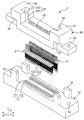
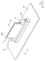
本発明の第1実施形態のプローブピンを備えた検査治具の斜視図であり、
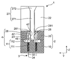
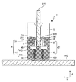
図1のII-II線に沿った断面図であり、
図1の検査治具の分解斜視図であり、
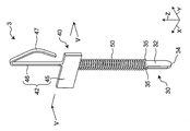
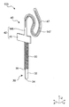
本発明の第1実施形態のプローブピンの斜視図であり、
図4のV-V線に沿った断面図であり、
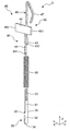
図4のプローブピンの分解斜視図であり、
図1の検査治具の検査状態を説明するための斜視図であり、
図7のVIII-VIII線に沿った断面図であり、
本発明の第2実施形態のプローブピンの斜視図であり、
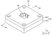
本発明の第1実施形態のプローブピンを備えた他の検査治具の斜視図であり、
図10のXI-XI線に沿った断面図であり、
図10の検査治具の分解斜視図であり、
図10の検査治具の検査状態を説明するための斜視図である。
以下、添付図面を参照して本発明の実施形態を説明する。なお、以下の説明では、図面に表された構成を説明するうえで、「上」、「下」、「左」、「右」等の方向を示す用語、及びそれらを含む別の用語を使用するが、それらの用語を使用する目的は図面を通じて実施形態の理解を容易にするためである。したがって、それらの用語は本発明の実施形態が実際に使用されるときの方向を示すものとは限らないし、それらの用語によって特許請求の範囲に記載された発明の技術的範囲が限定的に解釈されるべきでない。
(第1実施形態)
本発明の第1実施形態のプローブピン3を備えた検査治具1は、図1~図3に示すように、絶縁性のハウジング2と、このハウジング2内に収納された複数のプローブピン3とを備えている。
本発明の第1実施形態のプローブピン3を備えた検査治具1は、図1~図3に示すように、絶縁性のハウジング2と、このハウジング2内に収納された複数のプローブピン3とを備えている。
ハウジング2は、図1に示すように、上面視矩形状を有し、第1ハウジングの一例の下部ハウジング10と、下部ハウジング10上(図1のZ方向の上側)に設けられた第2ハウジングの一例の上部ハウジング20とで構成されている。また、ハウジング2の内部には、プローブピン3を収容保持する収容保持部4が設けられている。この収容保持部4は、図2に示すように、下部ハウジング10に設けられた保持部11と上部ハウジング20に設けられた収納部28とで構成されている。
下部ハウジング10は、図3に示すように、複数のプローブピン3を保持するための複数の保持部11と、下部ハウジング10および上部ハウジング20を位置決めするための4つの係合突部12と、下部ハウジング10と上部ハウジング20とを固定すると共に、ハウジング2を基板等に固定するための一対の取付孔13とを有している。
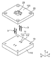
各保持部11は、下部ハウジング10をZ方向に貫通する貫通孔111と、この貫通孔111に連通し、かつ、下部ハウジング10の上面にY方向に沿って延びるように設けられた保持溝部112とで構成されている。各保持部11は、下部ハウジング10の上面に、X方向に沿って延びる平行な2つの列を成すように、等間隔で配置されている。保持部11の2つの列は、図2に示すように、後述するプローブピン3の第2接点47が相互に対向するように、短手方向(Y方向)に間隔を空けて配置されている。すなわち、保持溝部112は、下部ハウジング10の上部ハウジング20に対向する面に設けられている。
各係合突部12は、下部ハウジング10の上面からZ方向の上側に向かって突出するように設けられている。また、各係合突部12は、下部ハウジング10のX方向の両端部の保持部11と取付孔13との間に、下部ハウジング10のX方向に延びる長側の両辺に対向するように配置されている。
各取付孔13は、下部ハウジング10をZ方向に貫通し、かつ、締結部材を挿入可能な形状を有し、下部ハウジング10のX方向の両端にそれぞれ配置されている(図3では一方のみ示す)。
上部ハウジング20は、図3に示すように、被検査物を支持するための一対の支持部21,22と、被検査物が挿入されかつ通電検査を行うための検査部(検査溝部)23と、下部ハウジング10および上部ハウジング20を位置決めするための4つの係合受部24(図3では2つのみ示す)と、上部ハウジング20を基板等に固定するための一対の取付孔25(図3では1つのみ示す)とを有している。
各支持部21,22は、上部ハウジング20の上面からZ方向に突出するように設けられ、上部ハウジング20のX方向の両端にそれぞれ配置されている。各支持部21,22の相互に対向する側面には、Z方向に延びる支持溝部26,27がそれぞれ設けられている。各支持溝部26,27は、図2に示すように、溝部261,271(図2では一方のみ示す)と、溝部261,271のZ方向の上側に連続する導入部262,272(図2では一方のみ示す)とで構成されている。各溝部261,271は、被検査物を挿入可能な略同一の幅を有している。また、各導入部262,272は、Z方向の上側に向かって次第に大きくなる幅を有している。
検査部23は、上部ハウジング20の上面にX方向に沿って設けられ、図2に示すように、Z方向に貫通している。この検査部23は、下部ハウジング10に上部ハウジング20を固定したときに、下部ハウジング10の保持部11の列の間に位置するように配置されている。また、検査部23は、X方向の両端が支持溝部26,27とそれぞれ連通している。
各係合受部24は、下部ハウジング10に上部ハウジング20を固定したときに、下部ハウジング10の対応する係合突部12が係合可能に設けられている。この係合受部24は、各支持部21,22のX方向の外側かつZ方向の下側の両隅部に配置されている。
各取付孔25は、上部ハウジング20をZ方向に貫通し、かつ、締結部材を挿入可能な形状を有している。この取付孔25は、下部ハウジング10に上部ハウジング20を固定したときに下部ハウジング10の取付孔13に一致するように、上部ハウジング20のX方向の両端にそれぞれ配置されている(図3では一方のみ示す)。
また、上部ハウジング20の底面には、図2に示すように、後述するプローブピン3の第2接点47を往復動作可能に収納するための複数の収納部28が設けられている。各収納部28は、複数の保持部11の各々に対応しており、下部ハウジング10に上部ハウジング20を固定したときに、対応する保持部11と連通し、かつ、Y方向に隣接する保持部11側に開口部281を有するように配置されている。また、各収納部28は、そのY方向の幅が、保持部11の保持溝部112のY方向の長さよりも小さくなるように設けられている。
すなわち、収容保持部4は、第2接点47が検査部23に挿入された被検査物の端子に接触可能な開口部281が設けられた収納部28と、外部に露出した第1接点34がハウジング2に取り付けられた基板の端子に接触可能な貫通孔111と、を有している。
各プローブピン3は、図4~図6に示すように、第1プランジャ30と、第2プランジャ40と、コイルばね50とで構成されている。第1,第2プランジャ30,40は、各々導電性を有しており、例えば電鋳法で形成されている。
第1実施形態のプローブピン3では、第1プランジャ30は、コイルばね50の一端からコイルばね50のZ方向に延びる中心線CL1に沿って挿入され、コイルばね50の内部に延びている。第2プランジャ40は、その板面が第1プランジャ30の板面と直交するように、コイルばね50の他端から中心線CL1(図5に示す)に沿って挿入され、コイルばね50の内部に延びている。また、第1プランジャ30および第2プランジャ40は、後述する第1挿入部31および第2挿入部41を介してコイルばね50の内部で相互に連結されている。
なお、第1プランジャ30の板厚方向(X方向)に直交する面を板面とし、第2プランジャ40の板厚方向(Y方向)に直交する面を板面とする。また、板面に直交する板厚方向に平行な面を側面とする。
第1プランジャ30は、図6に示すように、略同一の板厚で、幅方向(Y方向)に対称な矩形の板形状を有している。この第1プランジャ30は、コイルばね50の内部に配置された第1挿入部31と、この第1挿入部31と一体成形されかつコイルばね50の外部に露出した第1接触部32とで構成されている。
第1挿入部31は、その板面の先端側(図6の上側)に、第1挿入部31を貫通するガイド溝33を有している。このガイド溝33は、第1挿入部31の長手方向(図6の上下方向)に延びる矩形状で、第2プランジャ40の板厚よりも大きい幅を有している。
第1接触部32は、その先端(図6の下側)に設けられた第1接点34を有している。第1接点34は、板面視円弧状を有している。また、第1接触部32と第1挿入部31との境界部分には、一対の第1支持部35が設けられている。各第1支持部35は、第1接触部32の両側面から突出するように設けられており、中心線CL1に直交する方向に延びている。各第1支持部35は、その先端間の距離がコイルばね50の内径よりも大きく、コイルばね50のZ方向の下側の端部に接触してコイルばね50を抜け止め保持するようになっている。
なお、第1プランジャ30の中心線は、コイルばね50の中心線CL1と一致している。
第2プランジャ40は、図6に示すように、略同一の板厚を有し、コイルばね50の内部に配置された第2挿入部41と、この第2挿入部41と一体成形されかつコイルばね50の外部に露出した第2接触部42とで構成されている。
第2挿入部41は、中心線CL1に沿って延びる第1弾性片43および第2弾性片44で構成されている。第1弾性片43および第2弾性片44の各々は、第1プランジャ30の板厚よりも大きい間隔を空けて、互いに略平行に配置されている。また、第1弾性片43および第2弾性片44は、長さが異なっており、第1弾性片43が第2弾性片44よりも短くなるように設けられている。
第1弾性片43の第2弾性片44に対向する内側面の先端には、ガイド突起431が突出するように設けられている。このガイド突起431は、第1プランジャ30の第1挿入部31のガイド溝33に係合可能に構成されている。また、第2弾性片44の第1弾性片43に対向する内側面の先端には、接触突起441が突出するように設けられている。第1弾性片43および第2弾性片44は、第1弾性片43のガイド突起431が第1プランジャ30のガイド溝33に係合した状態で、第2弾性片44の接触突起441が第1プランジャ30のガイド溝33と第1支持部35との間の板面に接触可能に構成されている。
第2接触部42は、第2挿入部41が接続された第2支持部45と、この第2支持部45からZ方向の上側に向かって突出する弾性部46とで構成されている。
第2支持部45は、矩形の平板形状を有し、第2接触部42の第2挿入部41との境界部分に設けられ、X方向(中心線CL1に直交する方向)に延びている。この第2支持部45は、その両端451,452間の距離L1がコイルばね50の内径よりも大きく、コイルばね50のZ方向の上側の端部に接触してコイルばね50を抜け止め保持するようになっている。また、第2支持部45は、中心線CL1からX方向の右側の端451までの距離L1よりも中心線CL1からX方向の左側の端452までの距離L2の方が大きくなるように設けられている。
弾性部46は、中心線CL1に対して異なる角度で配置された連続する3つの直線部461,462,463で構成されている。第1直線部461は、第2支持部45から中心線CL1に沿って延びている。第2直線部461は、第1直線部461のZ方向の上側の端部に連続し、第1直線部461と鋭角を成すように延びている。第3直線部463は、第2直線部462のZ方向の下側の端部に連続し、第2直線部462と鈍角を成すように延びている。
各直線部461,462,463の接続部分はそれぞれ湾曲しており、第2直線部462と第3直線部463との接続部分が第2接点47を構成している。この第2接点47は、図5に示すように、中心線CL1からの距離L3が、中心線CL1から第2支持部45のX方向の右側の端451までの距離L2よりも大きくなるように配置されている。
なお、図5に示す自然状態の第2接点47に荷重を加え、X方向左向きに押し込んだ後、第2接点47に加えた力を解放すると、第2接点47は、弾性部46によってX方向右向きに付勢され、自然状態に復帰する。すなわち、弾性部46の弾性力によって、第2接点47のX方向の往復移動が行われる。
また、第1プランジャ30の第1挿入部31および第2プランジャ40の第2挿入部41は、図5に示すように、第2プランジャ40の第1弾性片43のガイド突起431が、第1プランジャ30のガイド溝33に係合し、かつ、第2プランジャ40の第2弾性片44の接触突起441が第1プランジャ30の第1挿入部31の板面と接触した状態で、スライド移動可能に連結されている。
コイルばね50は、例えば、炭素鋼あるいはステンレス鋼からなり、その中心線CL1(図5に示す)に沿って伸縮するように形成されている。このコイルばね50は、第1プランジャ30の第1挿入部31および第2プランジャ40の第2挿入部41を挿入可能な内径を有している。また、このコイルばね50は、図2に示すように、下部ハウジング10の保持部11の貫通孔111に挿入可能な外径を有している。
なお、コイルばね50は、図4に示すように、第1プランジャ30と第2プランジャ40とが互いに連結された状態では、その両端が、第1プランジャ30の第1支持部35と、第2プランジャ40の第2支持部45とで抜け止め保持され、常時圧縮されるようにバネ長が調整されている。
次に、第1実施形態のプローブピン3を備える検査治具1の組立工程について説明する。
最初に、プローブピン3を組み立てる。まず、コイルばね50の一端側から中心線CL1に沿って第1プランジャ30の第1挿入部31を挿入する一方、コイルばね50の他端側から中心線CL1に沿って第2プランジャ40の第2挿入部41を挿入する。このとき、第1プランジャ30および第2プランジャ40の各々は、各板面が相互に直交するように挿入される。
第1プランジャ30および第2プランジャ40の各々をコイルばね50の内部に挿入していくと、第2プランジャ40の接触突起441が、第1プランジャ30の第1挿入部31の板面と接触し、かつ、第2プランジャ40のガイド突起431が、第1プランジャ30のガイド溝33に係合され、第1,第2プランジャ30,40が相互に連結される。これにより、各プローブピン3が組み立てられる。
各プローブピン3の組み立てが完了すると、各プローブピン3を下部ハウジング10の保持部11にそれぞれ組み付ける。このとき、図2に示すように、各プローブピン3は、第1プランジャ30をZ方向の上側から対応する保持部11の貫通孔111に挿入し、第2支持部45を保持溝部112に挿入する。これにより、各プローブピン3は、第1接点34を含む第1接触部32の一部が下部ハウジング10のZ方向の下側に露出し、かつ、第2接点47を含む第2接触部42の一部が下部ハウジング10のZ方向の上側に露出した状態で、下部ハウジング10に保持される。
全ての保持部11にプローブピン3を組み付けた後、下部ハウジング10のZ方向の上側から上部ハウジング20を取り付ける。このとき、下部ハウジング10のZ方向の上側に露出している第2接触部42の各々が、上部ハウジング20の底面の対応する収納部28に収納され、第2接点47が検査部23内に配置される。また、図2に示すように、各第2支持部45が、下部ハウジング10と上部ハウジング20とで挟持され、各プローブピン3が固定される。
そして、図7に示すように、一体となった下部ハウジング10の各取付孔13と上部ハウジング20の対応する取付孔25とに締結部材106をそれぞれ挿入し、検査治具1を基板100に固定する。このとき、検査治具1は、図8に示すように、各プローブピン3の第1接点34と基板100の端子105とが接触するように固定される。こうして、検査治具1の組立工程が終了する。
このようにして組み立てた検査治具1は、両面基板のような両面に電極のある被検査物の一例のデバイス200の導通検査に用いられる。この導通検査は、図7に示すように、デバイス200を検査部23に挿入して行われる。このとき、デバイス200は、X方向の両端が各支持部21,22にそれぞれ保持され、また、図8に示すように、一対の対向面にそれぞれ設けられている複数の端子205の各々が各プローブピン3の第2接点47と接触するように、検査部23に挿入される。
第1実施形態のプローブピン3では、コイルばね50の中心線CL1に沿って往復移動可能な第1接点34と、コイルばね50の中心線CL1と交差する方向に直交する方向に往復移動可能な第2接点47とを備えている。このため、例えば、被検査物の端子を検査装置の端子と同一直線上に配置できず、一方の接点をコイルばねの中心線に対して交差する方向に往復移動させなければ被検査物の端子と検査装置の端子とに同時に接触できない場合であっても、被検査物の端子と検査装置の端子とに同時に接触できる。
また、第2プランジャ40の第2接点47の往復移動が弾性部46の弾性力により行われる。このため、コイルばね等の他の弾性部材を用いることなく第2接点47を往復移動させることができるので、部品点数が少なくなり、製造コストを低減できる。
また、検査治具1は、第1実施形態のプローブピン3を備えているので、被検査物の複雑化および多様化に対応できる。
また、プローブピン3の第2支持部45が、下部ハウジング10および上部ハウジング20で挟持されているので、プローブピン3を容易に着脱できる。このため、複数のプローブピン3の1つが壊れたとしても、この壊れたプローブピン3のみを簡単に取り替えることができる。
(第2実施形態)
図9は、第2実施形態のプローブピン103を示す斜視図である。この第2実施形態では、第1実施形態と同一部分に同一参照番号を付して説明を省略し、第1実施形態と異なる点について説明する。
図9は、第2実施形態のプローブピン103を示す斜視図である。この第2実施形態では、第1実施形態と同一部分に同一参照番号を付して説明を省略し、第1実施形態と異なる点について説明する。
第2実施形態のプローブピン103は、図9に示すように、第2プランジャ40に波状を有する弾性部146を設けている点で、第1実施形態のプローブピン3と異なっている。
弾性部146には、弾性部146を板厚方向に貫通する貫通孔147が設けられている。これにより、第2接点47の復帰力を調整することができる。
このように、第2プランジャ40の弾性部は、第2接点47がコイルばね50の中心線CL1と交差する方向に往復移動可能であれば、任意の形状および構造を採用することができる。すなわち、第2接点47は、コイルばね50の中心線CL1に対して直交する方向に往復移動可能に設ける場合に限らず、コイルばね50の中心線CL1に対して交差する方向であれば、任意の方向に往復移動可能に設けてもよい。
(その他の実施形態)
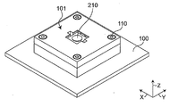
第1実施形態のプローブピン3および第2実施形態のプローブピン103は、図7に示すように、デバイス200の導通検査に用いる検査治具1に限らない。例えば、図10~図13に示すように、LED素子210の導通検査に用いる検査治具101に用いることもできる。なお、図10~図13では、第1実施形態のプローブピン3を示している。
第1実施形態のプローブピン3および第2実施形態のプローブピン103は、図7に示すように、デバイス200の導通検査に用いる検査治具1に限らない。例えば、図10~図13に示すように、LED素子210の導通検査に用いる検査治具101に用いることもできる。なお、図10~図13では、第1実施形態のプローブピン3を示している。
検査治具101は、図10~図12に示すように、下部ハウジング110と上部ハウジング120とで構成された略正方体のハウジング102と、ハウジング102内に収納された4本のプローブピン3とを備えている。
下部ハウジング110は、図12に示すように、4つの保持部11と、各隅部に設けられた取付孔13とを有している。
各保持部11は、下部ハウジング110をZ方向に貫通する貫通孔111と、この貫通孔111に連通し、かつ、下部ハウジング110の上面にY方向に沿って延びるように設けられた保持溝部112とで構成されている。各保持部11は、下部ハウジング110の上面に、X方向に沿って延びる平行な2つの列を成すように、等間隔で配置されている。また、各保持部11の2つの列は、図11に示すように、プローブピン3の第2接点47が相互に対向するように、Y方向に間隔を空けて配置されている。
また、上部ハウジング120は、中央部に設けられた検査部(検査凹部)23と、各隅部に設けられた取付孔25とを有している。
この検査治具101の導通検査は、図13に示すように、基板100上に固定され、LED素子210を検査部23に挿入して行われる。このとき、LED素子210は、図示していないが、一対の対向面に設けられている端子がプローブピン3の第2接点47と接触するように、検査部23に挿入される。
第1プランジャ30の第1接点34の形状は、円弧状に限らず、三角形あるいは四角形等、プローブピンの設計等に応じて、適宜選択できる。
第2プランジャ40の第1弾性片43のガイド突起431は、第1プランジャ30のガイド溝33に挿入嵌合できると共に、ガイド溝33内をスライド移動できるものであればよく、形状、大きさ等は、適宜選択できる。
第2プランジャ40の第2支持部45は、コイルばね50を支持することができ、かつ、下部ハウジング10および上部ハウジング20に挟持されることができればよく、形状、大きさ等は、適宜選択できる。
下部ハウジング10の保持部11は、用いるプローブピンに応じて、形状、大きさ等を適宜選択できる。
第1,第2プランジャ30,40の板厚は、同一に限らず、部分により異なる板厚を有するようにしてもよい。
第1,第2プランジャ30,40は、設計に応じて、めっき,コーティング等の表面処理を行うこともできる。
第1,第2プランジャ30,40は、電鋳法に限らず、可能であれば、任意の製造方法を採用することができる。
第1プランジャ30にガイド溝33を設け、第2プランジャ40に第1,第2弾性片43,44を設けているが、これに限らない。例えば、第1プランジャに第1,第2弾性片を設け、第2プランジャにガイド溝を設けてもよい。
第1,第2プランジャ30,40は、コイルばね50の両端からそれぞれ挿入したときに、相互にスライド移動可能かつ導通可能に連結できるものであれば、任意の構成を採用できる。
以上、図面を参照して本発明における種々の実施形態を詳細に説明したが、最後に、本発明の種々の態様について説明する。
本発明の第1態様のプローブピンは、
中心線に沿って伸縮するコイルばねと、
前記コイルばねの一端から前記中心線に沿って前記コイルばねの内部に挿入された導電性の第1プランジャと、
前記コイルばねの他端から前記中心線に沿って前記コイルばねの内部に挿入された導電性の第2プランジャと、
を備え、
前記第1プランジャが、
前記コイルばねの内部に挿入された第1挿入部と、
前記第1挿入部に連続すると共に、前記中心線に沿って往復移動可能な第1接点が設けられた第1接触部と、
前記第1接触部の前記第1挿入部との境界部分に設けられ、前記中心線に交差する方向に延びると共に、前記コイルばねを支持する第1支持部と、
を有し、
前記第2プランジャが、
前記コイルばねの内部に挿入され、かつ、前記第1挿入部にスライド移動可能に連結された第2挿入部と、
前記中心線と交差する方向に往復移動可能な第2接点が設けられた第2接触部と、
前記第2接触部の前記第2挿入部との境界部分に設けられ、前記中心線に交差する方向に延びると共に、前記コイルばねを支持する第2支持部と、
を有する。
中心線に沿って伸縮するコイルばねと、
前記コイルばねの一端から前記中心線に沿って前記コイルばねの内部に挿入された導電性の第1プランジャと、
前記コイルばねの他端から前記中心線に沿って前記コイルばねの内部に挿入された導電性の第2プランジャと、
を備え、
前記第1プランジャが、
前記コイルばねの内部に挿入された第1挿入部と、
前記第1挿入部に連続すると共に、前記中心線に沿って往復移動可能な第1接点が設けられた第1接触部と、
前記第1接触部の前記第1挿入部との境界部分に設けられ、前記中心線に交差する方向に延びると共に、前記コイルばねを支持する第1支持部と、
を有し、
前記第2プランジャが、
前記コイルばねの内部に挿入され、かつ、前記第1挿入部にスライド移動可能に連結された第2挿入部と、
前記中心線と交差する方向に往復移動可能な第2接点が設けられた第2接触部と、
前記第2接触部の前記第2挿入部との境界部分に設けられ、前記中心線に交差する方向に延びると共に、前記コイルばねを支持する第2支持部と、
を有する。
言い換えると、第1態様のプローブピンは、
中心線に沿って伸縮するコイルばねと、
前記コイルばねの一端から前記中心線に沿って前記コイルばねの内部に延びた導電性の第1プランジャと、
前記コイルばねの他端から前記中心線に沿って前記コイルばねの内部に延びた導電性の第2プランジャと、
を備え、
前記第1プランジャが、
前記コイルばねの内部に配置された第1挿入部と、
前記コイルばねの外部に露出していると共に、前記中心線に沿って往復移動可能な第1接点が設けられた第1接触部と、
前記第1接触部と前記第1挿入部との境界部分に設けられ、前記中心線に交差する方向に延びると共に、前記コイルばねの一端に接触して前記コイルばねを抜け止め保持する第1支持部と、
を有し、
前記第2プランジャが、
前記コイルばねの内部に配置されかつ前記第1挿入部にスライド移動可能に連結された第2挿入部と、
前記コイルばねの外部に露出していると共に、前記中心線と交差する方向に往復移動可能な第2接点が設けられた第2接触部と、
前記第2接触部と前記第2挿入部との境界部分に設けられ、前記中心線に交差する方向に延びると共に、前記コイルばねの他端に接触して前記コイルばねを抜け止め保持する第2支持部と、
を有する。
中心線に沿って伸縮するコイルばねと、
前記コイルばねの一端から前記中心線に沿って前記コイルばねの内部に延びた導電性の第1プランジャと、
前記コイルばねの他端から前記中心線に沿って前記コイルばねの内部に延びた導電性の第2プランジャと、
を備え、
前記第1プランジャが、
前記コイルばねの内部に配置された第1挿入部と、
前記コイルばねの外部に露出していると共に、前記中心線に沿って往復移動可能な第1接点が設けられた第1接触部と、
前記第1接触部と前記第1挿入部との境界部分に設けられ、前記中心線に交差する方向に延びると共に、前記コイルばねの一端に接触して前記コイルばねを抜け止め保持する第1支持部と、
を有し、
前記第2プランジャが、
前記コイルばねの内部に配置されかつ前記第1挿入部にスライド移動可能に連結された第2挿入部と、
前記コイルばねの外部に露出していると共に、前記中心線と交差する方向に往復移動可能な第2接点が設けられた第2接触部と、
前記第2接触部と前記第2挿入部との境界部分に設けられ、前記中心線に交差する方向に延びると共に、前記コイルばねの他端に接触して前記コイルばねを抜け止め保持する第2支持部と、
を有する。
第1態様のプローブピンによれば、コイルばねの中心線に沿って往復移動可能な第1接点と、コイルばねの中心線と交差する方向に往復移動可能な第2接点とを備えている。このため、例えば、被検査物の端子を検査装置の端子と同一直線上に配置できず、一方の接点をコイルばねの中心線に対して交差する方向に往復移動させなければ被検査物の端子と検査装置の端子とに同時に接触できない場合であっても、被検査物の端子と検査装置の端子とに同時に接触できる。
本発明の第2態様のプローブピンでは、
前記第2接触部が、荷重が加えられていない状態である自然状態に復帰するように前記第2接点を前記中心線に交差する方向に付勢する弾性部を有し、この弾性部の弾性力によって、前記第2接点の往復移動が行われる。
前記第2接触部が、荷重が加えられていない状態である自然状態に復帰するように前記第2接点を前記中心線に交差する方向に付勢する弾性部を有し、この弾性部の弾性力によって、前記第2接点の往復移動が行われる。
第2態様のプローブピンによれば、第2接点の往復移動が弾性部の弾性力により行われる。このため、コイルばね等の他の弾性部材を用いることなく第2接点を往復移動させることができるので、部品点数が少なくなり、製造コストを低減できる。
本発明の第3態様の検査治具は、
被検査物の一対の対向面にそれぞれ設けられた端子と、基板上に設けられた端子との間の導通検査を行うための検査治具であって、
前記被検査物を挿入可能な検査部を有するハウジングと、
前記被検査物が前記検査部に挿入されたときに前記被検査物の端子に前記第2接点が接触し、かつ、前記基板上に前記ハウジングを取り付けたときに前記基板の端子に前記第1接点が接触できるように、前記ハウジング内に着脱可能に収納されている、請求項1または2に記載のプローブピンと、
を備える。
被検査物の一対の対向面にそれぞれ設けられた端子と、基板上に設けられた端子との間の導通検査を行うための検査治具であって、
前記被検査物を挿入可能な検査部を有するハウジングと、
前記被検査物が前記検査部に挿入されたときに前記被検査物の端子に前記第2接点が接触し、かつ、前記基板上に前記ハウジングを取り付けたときに前記基板の端子に前記第1接点が接触できるように、前記ハウジング内に着脱可能に収納されている、請求項1または2に記載のプローブピンと、
を備える。
言い換えると、第3態様の検査治具は、
被検査物の一対の対向面にそれぞれ設けられた端子と、基板上に設けられた端子との間の導通検査を行うための検査治具であって、
前記プローブピンと、
前記被検査物を挿入可能な検査部と、前記プローブピンを収容保持する保持部とを有するハウジングと、
を備え、
前記収容保持部が、前記第2接点が前記検査部に挿入された前記被検査物の前記端子に接触可能な開口部が設けられた収納部と、外部に露出した前記第1接点が前記ハウジングに取り付けられた前記基板の前記端子に接触可能な貫通孔と、を有する。
被検査物の一対の対向面にそれぞれ設けられた端子と、基板上に設けられた端子との間の導通検査を行うための検査治具であって、
前記プローブピンと、
前記被検査物を挿入可能な検査部と、前記プローブピンを収容保持する保持部とを有するハウジングと、
を備え、
前記収容保持部が、前記第2接点が前記検査部に挿入された前記被検査物の前記端子に接触可能な開口部が設けられた収納部と、外部に露出した前記第1接点が前記ハウジングに取り付けられた前記基板の前記端子に接触可能な貫通孔と、を有する。
第3態様の検査治具によれば、前記プローブピンを備えているので、被検査物の複雑化および多様化に対応できる。
本発明の第4態様の検査治具は、
前記ハウジングが、
前記第1,第2接触部の少なくとも一部が露出するように前記プローブピンを保持する第1ハウジングと、
前記第1ハウジングに連結されると共に、前記検査部と、前記検査部に連通し、かつ、前記第2接点が往復移動できるように前記第2接触部を収納する収納部と、が設けられた第2ハウジングと、
を有し、
前記プローブピンの第2支持部が、前記第1,第2ハウジングにより挟持されている。
前記ハウジングが、
前記第1,第2接触部の少なくとも一部が露出するように前記プローブピンを保持する第1ハウジングと、
前記第1ハウジングに連結されると共に、前記検査部と、前記検査部に連通し、かつ、前記第2接点が往復移動できるように前記第2接触部を収納する収納部と、が設けられた第2ハウジングと、
を有し、
前記プローブピンの第2支持部が、前記第1,第2ハウジングにより挟持されている。
言い換えると、第4態様の検査治具は、
前記ハウジングが、
前記第1接触部および第2接触部の少なくとも一部が露出するように前記プローブピンを内部に保持する前記貫通孔と、前記プローブピンの第2支持部が挿入される保持溝部とを有する第1ハウジングと、
前記第1ハウジングに連結されていると共に、前記検査部と前記収納部とが設けられた第2ハウジングと、
を有し、
前記保持溝部が、前記第1ハウジングの前記第2ハウジングに対向する面に設けられており、前記第2支持部が、前記第1ハウジングおよび第2ハウジングにより挟持されている、請求項3に記載の検査治具。
前記ハウジングが、
前記第1接触部および第2接触部の少なくとも一部が露出するように前記プローブピンを内部に保持する前記貫通孔と、前記プローブピンの第2支持部が挿入される保持溝部とを有する第1ハウジングと、
前記第1ハウジングに連結されていると共に、前記検査部と前記収納部とが設けられた第2ハウジングと、
を有し、
前記保持溝部が、前記第1ハウジングの前記第2ハウジングに対向する面に設けられており、前記第2支持部が、前記第1ハウジングおよび第2ハウジングにより挟持されている、請求項3に記載の検査治具。
第4態様の検査治具によれば、プローブピンの第2支持部が第1,第2ハウジングで挟持されるので、プローブピンを容易に着脱できる。このため、複数のプローブピンの1つが壊れたとしても、この壊れたプローブピンのみを簡単に取り替えることができる。
なお、前記様々な実施形態又は変形例のうちの任意の実施形態又は変形例を適宜組み合わせることにより、それぞれの有する効果を奏するようにすることができる。また、実施形態同士の組み合わせ又は実施例同士の組み合わせ又は実施形態と実施例との組み合わせが可能であると共に、異なる実施形態又は実施例の中の特徴同士の組み合わせも可能である。
本発明は、添付図面を参照しながら好ましい実施形態に関連して充分に記載されているが、この技術の熟練した人々にとっては種々の変形や修正は明白である。そのような変形や修正は、添付した請求の範囲による本発明の範囲から外れない限りにおいて、その中に含まれると理解されるべきである。
本発明に係るプローブピンおよび検査治具は、前記実施形態に限らず、他の半導体集積回路および半導体デバイス等の検査ユニットに適用できる。
1,101 検査治具
2,102 ハウジング
3,103 プローブピン
10,110 下部ハウジング(第1ハウジング)
11 保持部
111 貫通孔
112 保持溝部
12 係合突部
13 取付孔
20,120 上部ハウジング(第2ハウジング)
21,22 支持部
23 検査部
24 係合受部
25 取付孔
26,27 支持溝部
261,271 溝部
262,272 導入部
28 収納部
281 開口部
30 第1プランジャ
31 第1挿入部
32 第1接触部
33 ガイド溝
34 第1接点
35 第1支持部
40 第2プランジャ
41 第2挿入部
42 第2接触部
43 第1弾性片
431 ガイド突起
44 第2弾性片
441 接触突起
45 第2支持部
46 弾性部
461 第1直線部
462 第2直線部
463 第3直線部
47 第2接点
50 コイルばね
100 基板
105 端子
106 締結部材
200 デバイス
205 端子
210 LED素子
2,102 ハウジング
3,103 プローブピン
10,110 下部ハウジング(第1ハウジング)
11 保持部
111 貫通孔
112 保持溝部
12 係合突部
13 取付孔
20,120 上部ハウジング(第2ハウジング)
21,22 支持部
23 検査部
24 係合受部
25 取付孔
26,27 支持溝部
261,271 溝部
262,272 導入部
28 収納部
281 開口部
30 第1プランジャ
31 第1挿入部
32 第1接触部
33 ガイド溝
34 第1接点
35 第1支持部
40 第2プランジャ
41 第2挿入部
42 第2接触部
43 第1弾性片
431 ガイド突起
44 第2弾性片
441 接触突起
45 第2支持部
46 弾性部
461 第1直線部
462 第2直線部
463 第3直線部
47 第2接点
50 コイルばね
100 基板
105 端子
106 締結部材
200 デバイス
205 端子
210 LED素子
Claims (4)
- 中心線に沿って伸縮するコイルばねと、
前記コイルばねの一端から前記中心線に沿って前記コイルばねの内部に延びた導電性の第1プランジャと、
前記コイルばねの他端から前記中心線に沿って前記コイルばねの内部に延びた導電性の第2プランジャと、
を備え、
前記第1プランジャが、
前記コイルばねの内部に配置された第1挿入部と、
前記コイルばねの外部に露出していると共に、前記中心線に沿って往復移動可能な第1接点が設けられた第1接触部と、
前記第1接触部と前記第1挿入部との境界部分に設けられ、前記中心線に交差する方向に延びると共に、前記コイルばねの一端に接触して前記コイルばねを抜け止め保持する第1支持部と、
を有し、
前記第2プランジャが、
前記コイルばねの内部に配置されかつ前記第1挿入部にスライド移動可能に連結された第2挿入部と、
前記コイルばねの外部に露出していると共に、前記中心線と交差する方向に往復移動可能な第2接点が設けられた第2接触部と、
前記第2接触部と前記第2挿入部との境界部分に設けられ、前記中心線に交差する方向に延びると共に、前記コイルばねの他端に接触して前記コイルばねを抜け止め保持する第2支持部と、
を有する、プローブピン。 - 前記第2接触部が、荷重が加えられていない状態である自然状態に復帰するように前記第2接点を前記中心線に交差する方向に付勢する弾性部を有し、この弾性部の弾性力によって、前記第2接点の往復移動が行われる、請求項1に記載のプローブピン。
- 被検査物の一対の対向面にそれぞれ設けられた端子と、基板上に設けられた端子との間の導通検査を行うための検査治具であって、
請求項1または2に記載のプローブピンと、
前記被検査物を挿入可能な検査部と、前記プローブピンを収容保持する収容保持部とを有するハウジングと、
を備え、
前記収容保持部が、前記第2接点が前記検査部に挿入された前記被検査物の前記端子に接触可能な開口部が設けられた収納部と、外部に露出した前記第1接点が前記ハウジングに取り付けられた前記基板の前記端子に接触可能な貫通孔と、を有する、検査治具。 - 前記ハウジングが、
前記第1接触部および第2接触部の少なくとも一部が露出するように前記プローブピンを内部に保持する前記貫通孔と、前記プローブピンの第2支持部が挿入される保持溝部とが設けられた第1ハウジングと、
前記第1ハウジングに連結されていると共に、前記検査部と前記収納部とが設けられた第2ハウジングと、
を有し、
前記保持溝部が、前記第1ハウジングの前記第2ハウジングに対向する面に設けられており、前記第2支持部が、前記第1ハウジングおよび第2ハウジングにより挟持されている、請求項3に記載の検査治具。
Applications Claiming Priority (2)
| Application Number | Priority Date | Filing Date | Title |
|---|---|---|---|
| JP2015-182126 | 2015-09-15 | ||
| JP2015182126A JP6641818B2 (ja) | 2015-09-15 | 2015-09-15 | プローブピン、および、これを備えた検査治具 |
Publications (1)
| Publication Number | Publication Date |
|---|---|
| WO2017047495A1 true WO2017047495A1 (ja) | 2017-03-23 |
Family
ID=58289301
Family Applications (1)
| Application Number | Title | Priority Date | Filing Date |
|---|---|---|---|
| PCT/JP2016/076460 Ceased WO2017047495A1 (ja) | 2015-09-15 | 2016-09-08 | プローブピン、および、これを備えた検査治具 |
Country Status (3)
| Country | Link |
|---|---|
| JP (1) | JP6641818B2 (ja) |
| TW (1) | TW201713953A (ja) |
| WO (1) | WO2017047495A1 (ja) |
Families Citing this family (6)
| Publication number | Priority date | Publication date | Assignee | Title |
|---|---|---|---|---|
| US10312616B2 (en) * | 2017-07-14 | 2019-06-04 | Molex, Llc | Card edge connector |
| JP6881343B2 (ja) | 2018-02-07 | 2021-06-02 | オムロン株式会社 | プローブピン、検査治具、検査ユニットおよび検査装置 |
| CN112005448B (zh) * | 2018-05-22 | 2022-09-23 | 欧姆龙株式会社 | 探针销 |
| JP2020034352A (ja) * | 2018-08-28 | 2020-03-05 | オムロン株式会社 | プローブピン用ハウジング、検査治具、検査ユニットおよび検査装置 |
| JP7647177B2 (ja) * | 2021-03-04 | 2025-03-18 | オムロン株式会社 | プローブピン、検査治具および検査治具ユニット |
| TWI833186B (zh) | 2022-03-29 | 2024-02-21 | 大陸商迪科特測試科技(蘇州)有限公司 | 探針及其彈性結構 |
Citations (2)
| Publication number | Priority date | Publication date | Assignee | Title |
|---|---|---|---|---|
| JP2004325306A (ja) * | 2003-04-25 | 2004-11-18 | Yokowo Co Ltd | 検査用同軸プローブおよびそれを用いた検査ユニット |
| JP2013511039A (ja) * | 2009-11-11 | 2013-03-28 | ハイコン カンパニー リミテッド | バネコンタクト及びバネコンタクト内蔵ソケット |
Family Cites Families (7)
| Publication number | Priority date | Publication date | Assignee | Title |
|---|---|---|---|---|
| JP4047456B2 (ja) * | 1998-05-29 | 2008-02-13 | 日置電機株式会社 | 回路基板検査装置 |
| JP4276163B2 (ja) * | 2004-11-12 | 2009-06-10 | サンコール株式会社 | Icソケット |
| JP2006234428A (ja) * | 2005-02-22 | 2006-09-07 | Omron Corp | コンタクトプローブおよび検査装置 |
| JP2009128211A (ja) * | 2007-11-26 | 2009-06-11 | Sensata Technologies Inc | プローブピン |
| JP5629611B2 (ja) * | 2011-03-01 | 2014-11-26 | 株式会社日本マイクロニクス | 接触子及び電気的接続装置 |
| WO2013061486A1 (ja) * | 2011-10-26 | 2013-05-02 | ユニテクノ株式会社 | コンタクトプローブおよびそれを備えた検査ソケット |
| JP2015152380A (ja) * | 2014-02-13 | 2015-08-24 | 日置電機株式会社 | 基板検査装置および基板検査方法 |
-
2015
- 2015-09-15 JP JP2015182126A patent/JP6641818B2/ja active Active
-
2016
- 2016-09-08 WO PCT/JP2016/076460 patent/WO2017047495A1/ja not_active Ceased
- 2016-09-12 TW TW105129530A patent/TW201713953A/zh unknown
Patent Citations (2)
| Publication number | Priority date | Publication date | Assignee | Title |
|---|---|---|---|---|
| JP2004325306A (ja) * | 2003-04-25 | 2004-11-18 | Yokowo Co Ltd | 検査用同軸プローブおよびそれを用いた検査ユニット |
| JP2013511039A (ja) * | 2009-11-11 | 2013-03-28 | ハイコン カンパニー リミテッド | バネコンタクト及びバネコンタクト内蔵ソケット |
Also Published As
| Publication number | Publication date |
|---|---|
| JP6641818B2 (ja) | 2020-02-05 |
| TW201713953A (zh) | 2017-04-16 |
| JP2017059363A (ja) | 2017-03-23 |
Similar Documents
| Publication | Publication Date | Title |
|---|---|---|
| KR101911005B1 (ko) | 프로브 핀, 검사 지그, 검사 유닛 및 검사 장치 | |
| JP6641818B2 (ja) | プローブピン、および、これを備えた検査治具 | |
| US10398051B2 (en) | Socket having a terminal unit assembly accommodated within a recess of a frame member | |
| KR101865533B1 (ko) | 소켓 | |
| JP7314633B2 (ja) | プローブピン、検査治具および検査ユニット | |
| JP4854612B2 (ja) | ソケット用アダプタ | |
| JPWO2019138505A1 (ja) | プローブピン、検査治具、検査ユニットおよび検査装置 | |
| US11187722B2 (en) | Probe pin and electronic device using the same | |
| US20180011127A1 (en) | Kelvin probe and kelvin inspection unit provided with same | |
| JP6642359B2 (ja) | プローブピンおよび検査ユニット | |
| KR102148842B1 (ko) | 검사구, 검사 유닛 및 검사 장치 | |
| JP7354534B2 (ja) | プローブピンおよび検査治具 | |
| JP6515516B2 (ja) | プローブピン、および、これを備えた電子デバイス | |
| JP2023121805A (ja) | プローブピン、検査治具および検査ユニット | |
| JP2022029833A (ja) | ソケット、ソケットユニット、検査治具および検査治具ユニット | |
| KR20210022670A (ko) | 프로브 유닛 | |
| JP2017223453A (ja) | 検査用治具 | |
| JP6582780B2 (ja) | プローブピンおよびこれを用いた検査治具 | |
| WO2020045066A1 (ja) | プローブピン用ハウジング、検査治具、検査ユニットおよび検査装置 | |
| JPWO2011065361A1 (ja) | 接続部材 | |
| JP6881354B2 (ja) | 検査ユニットおよび検査装置 | |
| WO2018042931A1 (ja) | プローブピン | |
| JP2020076664A (ja) | プローブピン、検査治具、検査ユニットおよび検査装置 | |
| JP6724674B2 (ja) | 表面実装コネクタ | |
| JP2017083295A (ja) | 電気部品用ソケット |
Legal Events
| Date | Code | Title | Description |
|---|---|---|---|
| 121 | Ep: the epo has been informed by wipo that ep was designated in this application |
Ref document number: 16846366 Country of ref document: EP Kind code of ref document: A1 |
|
| NENP | Non-entry into the national phase |
Ref country code: DE |
|
| 122 | Ep: pct application non-entry in european phase |
Ref document number: 16846366 Country of ref document: EP Kind code of ref document: A1 |