WO2017043403A1 - 渦電流式計器 - Google Patents
渦電流式計器 Download PDFInfo
- Publication number
- WO2017043403A1 WO2017043403A1 PCT/JP2016/075611 JP2016075611W WO2017043403A1 WO 2017043403 A1 WO2017043403 A1 WO 2017043403A1 JP 2016075611 W JP2016075611 W JP 2016075611W WO 2017043403 A1 WO2017043403 A1 WO 2017043403A1
- Authority
- WO
- WIPO (PCT)
- Prior art keywords
- lid
- cylindrical portion
- rotating shaft
- cylindrical
- eddy current
- Prior art date
- Legal status (The legal status is an assumption and is not a legal conclusion. Google has not performed a legal analysis and makes no representation as to the accuracy of the status listed.)
- Ceased
Links
Images



Classifications
-
- G—PHYSICS
- G01—MEASURING; TESTING
- G01D—MEASURING NOT SPECIALLY ADAPTED FOR A SPECIFIC VARIABLE; ARRANGEMENTS FOR MEASURING TWO OR MORE VARIABLES NOT COVERED IN A SINGLE OTHER SUBCLASS; TARIFF METERING APPARATUS; MEASURING OR TESTING NOT OTHERWISE PROVIDED FOR
- G01D11/00—Component parts of measuring arrangements not specially adapted for a specific variable
- G01D11/10—Elements for damping the movement of parts
- G01D11/12—Elements for damping the movement of parts using fluid damping
Definitions
- the present invention relates to an improved eddy current instrument.
- Vehicles are usually equipped with instruments such as speedometers and tachometers.
- instruments such as speedometers and tachometers.
- an eddy current type instrument in which a pointer is rotated by an eddy current generated when a magnet is rotated.
- Patent Document 1 As a conventional technique related to an eddy current type instrument, there is a technique disclosed in Patent Document 1.
- an eddy current type instrument has a base, a lid placed on the base, a first rotary shaft rotatably supported on the base, and the first rotary shaft.
- a magnet that is attached and rotates together with the first rotation shaft, a second rotation shaft that is rotatably attached to the lid, and rotation by an eddy current that is generated when the magnet is supported by the second rotation shaft.
- a damper mechanism for suppressing rapid rotation of the second rotating shaft and the rotor. The pointer visually recognized by the occupant is provided at the upper end of the second rotation shaft.
- the damper mechanism has an oil cup attached to the second rotating shaft and filled with oil, and a resistance portion extending from the lid toward the oil cup and having a tip immersed in the oil.
- the resistance portion is attached to the lid.
- An object of the present invention is to provide an eddy current type instrument capable of reducing the number of parts.
- the base the lid that covers the base, the first rotating shaft that is rotatably supported by the base, and the first rotating shaft that is attached to the first rotating shaft.
- a magnet that rotates with the rotating shaft, a second rotating shaft that is rotatably attached to the lid, and a rotor that is supported by the second rotating shaft and that rotates by eddy current generated when the magnet rotates.
- an eddy current meter having a damper mechanism for suppressing the rapid rotation of the second rotating shaft and the rotor
- the lid has an insertion hole into which the second rotating shaft is inserted while resin is used as a material
- the second rotating shaft is rotatably supported by the lid body in a state where the second rotating shaft is in contact with the inner peripheral surface of the insertion hole
- the damper mechanism has an oil cup attached to the second rotating shaft and filled with oil, and a resistance portion extending from the lid toward the oil cup and having a tip immersed in the oil,
- An eddy current instrument is provided in which the resistance portion is formed integrally with the lid.
- the resistance portion includes a cylindrical first cylindrical portion formed continuously with the lid body, and is continuous with the first cylindrical portion and is more than the first cylindrical portion.
- the resistance portion includes a cylindrical first cylindrical portion formed continuously with the lid body, and is continuous with the first cylindrical portion and is more than the first cylindrical portion.
- the second rotating shaft is inserted into and supported by the insertion hole of the lid, and the resistance portion of the damper mechanism is formed integrally with the lid. Since the second rotating shaft is inserted into the insertion hole of the resin lid, it is not necessary to separately provide a bearing for supporting the second rotating shaft. Furthermore, by forming the resistance portion integrally with the lid, it is not necessary to configure the resistance portion with a separate part. As a result, the number of parts can be reduced.
- the lid is made of resin.
- debris may be generated. Even if debris is generated, since the debris is a resin that does not have magnetism, the resin is not attracted to the magnet. Problems caused by a large amount of scrap attracted to the magnet biting into each part can be suppressed.
- resin is used for the cover body, generation of scraps can be prevented by integrally forming the insertion hole. By preventing the generation of waste, it is possible to prevent the waste from adhering to the second rotating shaft. By preventing the adhesion of the scrap, it is possible to suppress the rotation failure of the second rotating shaft caused by the biting of the scrap. Note that the screw tightening may be necessary when the lid is fixed to the base or when the dial is fixed to the lid.
- the weight of the eddy current type instrument can be reduced by using resin for the lid.
- the resistance portion includes a cylindrical first cylindrical portion formed continuously with the lid, and a cylindrical first cylindrical portion continuous with the first cylindrical portion and having a smaller diameter than the first cylindrical portion. 2 cylindrical parts.
- the diameter of the second cylindrical portion needs to be large enough to fit into the oil cup.
- the strength of the resistance portion can be increased by increasing the diameter of the first cylindrical portion that is closer to the lid than the second cylindrical portion.
- the distance from the tip of the second cylindrical part to the bottom surface of the oil cup is shorter than the distance from the step part to the oil cup. Due to the vibration, the second rotating shaft and the oil cup may be displaced in the axial direction of the second rotating shaft. At this time, the bottom surface of the oil cup contacts the tip of the second cylindrical portion before the oil cup contacts the stepped portion. Since the oil cup is filled with oil, the hit can be made softer than when the oil cup is brought into contact with the stepped portion.
- the resistance portion includes a cylindrical first cylindrical portion formed continuously with the lid, and a cylindrical first cylindrical portion continuous with the first cylindrical portion and having a smaller diameter than the first cylindrical portion. 2 cylindrical parts.
- the diameter of the second cylindrical portion needs to be large enough to fit into the oil cup.
- the strength of the resistance portion can be increased by increasing the diameter of the first cylindrical portion that is closer to the lid than the second cylindrical portion.
- the distance from the stepped portion to the oil cup is longer than the distance from the outer peripheral surface of the second cylindrical portion to the inner peripheral surface of the oil cup. It suppresses that oil leaks from between a level difference part and an oil cup by capillary action.
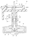
- FIG. 3 is a sectional view taken along line 3-3 in FIG. It is a principal part enlarged view of FIG. It is a perspective view explaining the travel distance display part shown by FIG.
- left and right refer to the left and right with reference to the occupant of the motorcycle
- front and rear refer to the front and rear with reference to the traveling direction of the motorcycle.
- Fr indicates front
- Rr indicates rear
- Le indicates left when viewed from the occupant
- Ri indicates right when viewed from the occupant
- Up indicates top
- Dn indicates bottom.
- the eddy current type instrument 20 is mounted on, for example, a motorcycle and used as a vehicle speedometer.
- the eddy current meter 20 is housed in a case 12 attached to the center portion of the handle pipe 11.
- the upper part of the case 12 is covered with a clear and transparent clear cover 13.
- FIG. 2 is a left side view of the eddy current type instrument 20 taken out from the case 12 of FIG.
- a scale 15 a is described on the upper surface of the dial 15, a scale 15 a is described.
- a dial 16 is rotatably disposed above the dial 15. The occupant can recognize the vehicle speed by visually recognizing the place indicated by the pointer 16.
- a travel distance display unit 60 that displays a travel distance is provided in front of the hands 16.
- the travel distance display unit 60 is provided integrally with the eddy current meter 20.
- the travel distance display unit 60 will be described later.
- FIG. 3 shows a cross-sectional view taken along line 3-3 of FIG.
- description of the dial 15 was abbreviate
- the eddy current type instrument 20 has components supported by a substantially rectangular base portion 21 and a resin cover portion 30 placed on the base portion 21.
- the base 21 is made of, for example, a cold-rolled cold-rolled steel plate. Two round holes 21 a and 21 b are formed in the base portion 21. A cylindrical member 23 made of metal is provided in the round hole 21 a opened in the approximate center of the base 21. A resin-made sliding bearing 24 is provided on the inner circumference of the cylindrical member 23, and a first rotating shaft 25 is provided on the inner circumference of the sliding bearing 24 so as to be rotatable.
- a cup-shaped magnetic conductor 26 and a donut-shaped magnet 27 are fixed to the upper portion of the first rotating shaft 25.
- the upper end of the first rotating shaft 25 is beaten downward, and a bearing 28 is disposed at the beaten portion.
- the magnet 27 for example, an Alnico magnet (Al—Ni—Co) is used.
- the magnetic conductor 26 is open upward.
- the magnet 27 is disposed so as to be housed in the magnetic conductor 26.
- a flexible cable can be connected to the lower end of the first rotating shaft 25.
- the flexible cable transmits the rotation of the wheel to the first rotation shaft 25. That is, the rotation of the wheel can be input to the first rotation shaft 25 via the flexible cable.
- the first rotating shaft 25 rotates, and the magnetic conductor 26 and the magnet 27 fixed to the first rotating shaft 25 rotate integrally.
- the base 21, the cylindrical member 23, and the sliding bearing 24 do not rotate.
- the cover portion 30 is, for example, an injection molded product formed by injection molding, and includes a wall portion 31 raised from the base portion 21 and a lid body 32 extending in parallel to the base portion 21 from the upper end of the wall portion 31. Become. Polybutylene terephthalate can be used as the resin for the cover portion 30.
- the lid 32 is provided with a circular insertion hole 32 a on the axis CL of the first rotating shaft 25.
- a metal second rotating shaft 41 is inserted into the insertion hole 32a. That is, the second rotating shaft 41 is disposed on the same axis line CL as the first rotating shaft 25.
- the second rotating shaft 41 is rotatably supported by the lid body 32 in a state where it is in contact with the inner peripheral surface of the insertion hole 32a. That is, the second rotating shaft 41 is directly supported by the lid body 32. The lower end of the second rotating shaft 41 is rotatably supported by the bearing 28.
- the second rotating shaft 41 passes through the opening 15 b formed in the dial 15.
- a pointer 16 is attached to the upper end of the second rotating shaft 41. Thereby, the pointer 16 rotates above the dial 15.
- a rotor 42 in which aluminum is formed in a cup shape is attached to the second rotating shaft 41.
- the rotor 42 has a bottom surface located above, and a cylindrical wall portion located between the magnet 27 and the magnetic conductor 26.
- the rotor 42 is rotated by an eddy current generated when the magnet 27 rotates.
- a damper mechanism 50 for suppressing the rapid rotation of the second rotating shaft 41 and the rotor 42 is provided on the upper portion of the rotor 42.
- a part of the lid 32 is a beard spring storage portion 32 b formed in a concave shape to store the beard spring 45.
- the whisker spring 45 has a central part attached to the second rotating shaft 41 and an end hooked on a hook 46 fixed to the whisker spring storage part 32b. The whisker spring 45 urges the second rotating shaft 41 in the direction opposite to the rotating direction due to the eddy current.
- the damper mechanism 50 includes an oil cup 52 attached to the second rotating shaft 41 and filled with oil 51, a resistance portion 53 extending from the lid 32 toward the oil cup 52 and having a tip immersed in the oil 51, Consists of.
- the resistance portion 53 is formed integrally with the lid 32 by, for example, injection molding.
- the resistance portion 53 includes a cylindrical first cylindrical portion 53a formed continuously with the lid 32, and a cylindrical second cylindrical portion continuous with the first cylindrical portion 53a and having a smaller diameter than the first cylindrical portion 53a. 53b, and a stepped stepped portion 53c formed at the boundary between the first cylindrical portion 53a and the second cylindrical portion 53b.
- the inner peripheral surface of the first cylindrical portion 53a and the inner peripheral surface of the second cylindrical portion 53b are continuous.
- the first cylindrical portion 53a and the second cylindrical portion 53b are formed along the axis CL.
- the distance L1 from the lower end of the second cylindrical portion 53b to the bottom surface of the oil cup 52 is shorter than the distance L2 from the step portion 53c to the oil cup 52.
- a distance L2 from the stepped portion 53c to the oil cup 52 is longer than a distance L3 from the outer peripheral surface of the second cylindrical portion 53b to the inner peripheral surface of the oil cup 52.
- a distance L4 from the inner peripheral surface of the second cylindrical portion 53b to the outer peripheral surface of the second rotating shaft 41 is longer than a distance L3 from the outer peripheral surface of the second cylindrical portion 53b to the inner peripheral surface of the oil cup 52.
- the first rotating shaft 25, the magnet 27, and the magnetic conductor 26 rotate. As these rotate, eddy currents are generated. Due to this eddy current, a force is applied to the rotor 42 in the rotational direction. As the speed at which the magnet 27 rotates increases, the eddy current increases. When the eddy current increases, the rotor 42 rotates against the biasing force of the whisker spring 45. When the rotor 42 rotates, the second rotating shaft 41 and the oil cup 52 rotate. As the second rotating shaft 41 rotates, the pointer 16 also rotates. On the other hand, the lid body 32, the resistance portion 53, and the whisker spring 45 do not rotate.
- the rotation speed of the first rotating shaft 25 also decreases. Thereby, an eddy current becomes small. Due to the urging force of the whisker spring 45, the second rotary shaft 41 is rotated in the direction opposite to that during acceleration. When the two-wheeled vehicle is stopped, the second rotating shaft 41 and the pointer 16 are returned to the positions before the two-wheeled vehicle travels.
- the eddy current type instrument 20 has a damper mechanism 50.
- the oil cup 52 can rotate, and the resistance portion 53 cannot rotate.
- the oil 51 is filled in the oil cup 52.
- the magnet 27 rotates, a force is applied to the oil cup 52 in the rotation direction.
- the oil 51 and the resistance portion 53 simultaneously apply a force to the oil cup 52 in the direction of suppressing rotation.
- the force for suppressing the rotation is applied to the oil cup 52 during acceleration and deceleration. Thereby, the rapid rotation of the second rotating shaft 41 and the rotor 42 is suppressed. By suppressing rapid rotation, shaking of the pointer 16 is suppressed.
- the travel distance display unit 60 will be described.
- FIG. 5 shows the eddy current meter 20 and the travel distance display unit 60 with the cover 30 (see FIG. 3) removed.
- the travel distance display unit 60 includes a horizontal axis 61 that rotates when the first rotary shaft 25 rotates and extends in the horizontal direction, a vertical axis 62 that rotates when the horizontal axis 61 rotates and extends in the vertical direction, And an accumulator 63 that rotates as the vertical axis 62 rotates.
- the lower end of the vertical axis 62 is inserted into the round hole 21 b of the base portion 21.
- the accumulator 63 is numbered.
- a first worm 71 is provided below the magnetic conductor 26 of the first rotating shaft 25, and a first gear 72 that meshes with the first worm 71 is provided on the horizontal shaft 61.
- the horizontal shaft 61 is further provided with a second gear 73, and the vertical axis 62 is provided with a second worm 74 that meshes with the second gear 73.
- a third worm 75 is further provided on the vertical axis 62.
- a third gear 76 is provided coaxially with the rotating shaft of the integrator 63. Between the third worm 75 and the third gear 76, both the third worm 75 and the third gear 76 are engaged, and a fourth gear 77 having a different number of teeth from the third gear 76 is provided. Is provided. That is, the fourth gear 77 is an idle gear that transmits the rotational force of the third worm 75 to the third gear 76.
- the first worm 71 When the motorcycle travels and the first rotating shaft 25 rotates, the first worm 71 also rotates. As the first worm 71 rotates, the first gear 72, the horizontal shaft 61, and the second gear 73 rotate. As the second gear 73 rotates, the second worm 74, the vertical axis 62, and the third worm 75 rotate. As the third worm 75 rotates, the fourth gear 77, the third gear 76, and the accumulator 63 rotate. The number given to the totalizer 63 indicates the travel distance of the two-wheeled vehicle, and the numerical value increases as the totalizer 63 rotates.
- the dial 15 has an opening 15 c formed above the accumulator 63. The occupant can visually recognize the number displayed on the totalizer 63 from the opening 15c.
- the second rotating shaft 41 is inserted into and supported by the insertion hole 32 a of the lid body 32, and the resistance portion 53 of the damper mechanism 50 is formed integrally with the lid body 32. Since the second rotating shaft 41 is inserted into the insertion hole 32a of the resin lid 32, there is no need to separately provide a bearing for supporting the second rotating shaft 41. Furthermore, by forming the resistance portion 53 integrally with the lid body 32, it is not necessary to configure the resistance portion 53 with a separate part. As a result, the number of parts can be reduced.
- the lid 32 is made of resin.
- the lid body 32 When the lid body 32 is screwed, debris may be generated. Even if debris is generated, the resin is not attracted to the magnet 27 because the debris is a non-magnetic resin. Problems caused by a large amount of scrap attracted to the magnet 27 biting into each component can be suppressed.
- resin is used for the cover body 32, generation
- the screw tightening may be necessary when the lid 32 is fixed to the base 21 or when the dial 15 is fixed to the lid 32.
- the eddy current meter 20 can be reduced in weight.
- the resistance portion 53 includes a cylindrical first cylindrical portion 53a formed continuously with the lid 32, and a cylindrical second cylindrical portion continuous with the first cylindrical portion 53a and having a smaller diameter than the first cylindrical portion 53a. And a cylindrical portion 53b.
- the diameter of the second cylindrical portion 53b needs to be large enough to fit into the oil cup.
- the distance L1 from the tip of the second cylindrical portion 53b to the bottom surface of the oil cup 52 is shorter than the distance L2 from the step portion 53c to the oil cup 52. Due to the vibration, the second rotary shaft 41 and the oil cup 52 may be displaced in the axial direction of the second rotary shaft 41 (the vertical direction in the drawing). At this time, the bottom surface of the oil cup 52 contacts the tip of the second cylindrical portion 53b before the oil cup 52 contacts the stepped portion 53c. Since the oil cup 52 is filled with the oil 51, the hit can be made softer than when the oil cup 52 is brought into contact with the stepped portion 53c.
- the distance L2 from the stepped portion 53c to the oil cup 52 is longer than the distance L3 from the outer peripheral surface of the second cylindrical portion 53b to the inner peripheral surface of the oil cup 52.
- the oil 51 is prevented from leaking between the stepped portion 53c and the oil cup 52 due to the capillary phenomenon.
- a whisker spring 45 (biasing member 45) for urging the second rotating shaft 41 in a direction against rotation due to eddy current (reverse direction when rotation due to eddy current is normal) is further provided.
- the whisker spring 45 is housed in a whisker spring housing part 32b (biasing member housing part 32b) formed in a concave shape on the lid 32.
- the length from the base portion 21 to the lid body 32 is shortened to achieve compactness, and the beard spring 45 can be protected by being housed in the beard spring housing portion 32b. Since the beard spring storage portion 32 b is formed in a concave shape in the lid body 32, the size of the lid body 32 is suppressed while the beard spring 45 is stored. In addition, by disposing the beard spring 45 outside the lid body 32, the attachment of the beard spring 45 can be improved.
- the eddy current type instrument according to the present invention can be mounted not only on a two-wheeled vehicle but also on a vehicle such as a four-wheeled vehicle or a three-wheeled vehicle or other vehicles.
- the eddy current type instrument has been described based on the example adopted for the vehicle speedometer, it can be applied to a tachometer or the like.
- the travel distance display unit may not be provided.
- the present invention is not limited to the examples as long as the operations and effects of the present invention are exhibited.
- the eddy current instrument of the present invention is suitable for a two-wheeled vehicle speedometer.
Landscapes
- Physics & Mathematics (AREA)
- General Physics & Mathematics (AREA)
- Instrument Panels (AREA)
- Fluid-Damping Devices (AREA)
Abstract
部品点数の削減を図ることのできる渦電流式計器を提供すること。 渦電流式計器(20)は、基部(21)と、基部(21)に被せられた蓋体(32)と、基部(21)に回転可能に支持された第1の回転軸(25)と、第1の回転軸(25)に取り付けられ回転可能な磁石(27)と、蓋体(32)に回転可能に取り付けられた第2の回転軸(41)と、第2の回転軸(41)に支持され磁石(27)が回転した際に発生する渦電流によって回転するロータ(42)と、これらの第2の回転軸(41)及びロータ(42)の急激な回転を抑制するためのダンパ機構(50)と、を有する。蓋体(32)は、素材に樹脂が用いられる。第2の回転軸(41)は、蓋体(32)の差込穴(32a)の内周面に接触した状態で、蓋体(32)によって支持されている。ダンパ機構(50)の抵抗部(53)は、蓋体(32)に一体的に形成されている。
Description
本発明は、改良された渦電流式計器に関する。
車両には、通常、車速計やタコメータ等の計器が搭載されている。これらの計器として、磁石を回転させた際に発生する渦電流によって指針を回転させる、渦電流式の計器が知られている。渦電流式計器に関する従来技術として、特許文献1に開示される技術がある。
特許文献1に示されるような、渦電流式計器は、基部と、この基部に被せられた蓋体と、基部に回転可能に支持された第1の回転軸と、この第1の回転軸に取り付けられ第1の回転軸と共に回転する磁石と、蓋体に回転可能に取り付けられた第2の回転軸と、この第2の回転軸に支持され磁石が回転した際に発生する渦電流によって回転するロータと、これらの第2の回転軸及びロータの急激な回転を抑制するためのダンパ機構と、を有する。乗員が視認する指針は、第2の回転軸の上端に設けられている。
ダンパ機構は、第2の回転軸に取り付けられオイルが充填されたオイルカップと、このオイルカップに向かって蓋体から延び先端がオイルに浸かっている抵抗部と、を有している。抵抗部は、蓋体に取り付けられている。
一般に、渦電流式計器の部品点数を削減することができれば、部品コストを低下させることができ好ましい。
本発明は、部品点数の削減を図ることのできる渦電流式計器の提供を課題とする。
請求項1による発明によれば、基部と、この基部に被せられた蓋体と、前記基部に回転可能に支持された第1の回転軸と、この第1の回転軸に取り付けられ前記第1の回転軸と共に回転する磁石と、前記蓋体に回転可能に取り付けられた第2の回転軸と、この第2の回転軸に支持され前記磁石が回転した際に発生する渦電流によって回転するロータと、これらの第2の回転軸及びロータの急激な回転を抑制するためのダンパ機構と、を有する渦電流式計器において、
前記蓋体は、素材に樹脂が用いられると共に、前記第2の回転軸が差し込まれる差込穴を有し、
前記第2の回転軸は、前記差込穴の内周面に接触した状態で前記蓋体によって回転可能に支持され、
前記ダンパ機構は、前記第2の回転軸に取り付けられオイルが充填されたオイルカップと、このオイルカップに向かって前記蓋体から延び先端が前記オイルに浸かっている抵抗部と、を有し、
前記抵抗部は、前記蓋体に一体的に形成されていることを特徴とする渦電流式計器が提供される。
前記蓋体は、素材に樹脂が用いられると共に、前記第2の回転軸が差し込まれる差込穴を有し、
前記第2の回転軸は、前記差込穴の内周面に接触した状態で前記蓋体によって回転可能に支持され、
前記ダンパ機構は、前記第2の回転軸に取り付けられオイルが充填されたオイルカップと、このオイルカップに向かって前記蓋体から延び先端が前記オイルに浸かっている抵抗部と、を有し、
前記抵抗部は、前記蓋体に一体的に形成されていることを特徴とする渦電流式計器が提供される。
請求項2に記載のごとく、好ましくは、前記抵抗部は、前記蓋体に連続して形成された円筒状の第1円筒部と、この第1円筒部に連続し前記第1円筒部よりも小径な円筒状の第2円筒部と、これらの第1円筒部及び第2円筒部の境界に形成された段差状の段差部と、を有し、
前記第2円筒部の先端から前記オイルカップの底面までの距離は、前記段差部から前記オイルカップまでの距離よりも短い。
前記第2円筒部の先端から前記オイルカップの底面までの距離は、前記段差部から前記オイルカップまでの距離よりも短い。
請求項3に記載のごとく、好ましくは、前記抵抗部は、前記蓋体に連続して形成された円筒状の第1円筒部と、この第1円筒部に連続し前記第1円筒部よりも小径な円筒状の第2円筒部と、これらの第1円筒部及び第2円筒部の境界に形成された段差状の段差部と、を有し、
前記段差部から前記オイルカップまでの距離は、前記第2円筒部の外周面から前記オイルカップの内周面までの距離よりも長い。
前記段差部から前記オイルカップまでの距離は、前記第2円筒部の外周面から前記オイルカップの内周面までの距離よりも長い。
請求項1に係る発明では、第2の回転軸は、蓋体の差込穴に差し込まれて支持されていると共に、ダンパ機構の抵抗部は、蓋体に一体的に形成されている。樹脂製の蓋体の差込穴に第2の回転軸を差し込むため、第2の回転軸を支持する軸受を別途設ける必要がない。さらに、抵抗部を蓋体に一体的に形成することにより、抵抗部を別部品によって構成する必要がなくなる。これらのことにより、部品点数の削減を図ることができる。
加えて、蓋体は、素材に樹脂が用いられる。蓋体をねじ締めする際に、屑が発生することがある。屑が発生したとしても、屑が磁性を有しない樹脂であるため、樹脂が磁石に引き寄せられない。磁石に引き寄せられた多量の屑が各部品に噛み込むことによる不具合を抑制することができる。また、蓋体は、素材に樹脂が用いられるため、差込穴を一体成形することにより、屑の発生を防止することができる。屑の発生を防止することにより、第2の回転軸に屑が付着することを防止することができる。屑の付着を防止することにより、屑が噛み込むことによる第2の回転軸の回転不良を抑制することができる。なお、ねじ締めは、蓋体を基部に固定する場合や、文字盤を蓋体に固定する際に必要となりうる。
加えて、蓋体に樹脂を用いることにより、渦電流式計器の軽量化を図ることができる。
請求項2に係る発明では、抵抗部は、蓋体に連続して形成された円筒状の第1円筒部と、この第1円筒部に連続し第1円筒部よりも小径な円筒状の第2円筒部と、を有している。第2円筒部の径は、オイルカップに入る大きさとする必要がある。第2円筒部よりも蓋体に近い第1円筒部の径を大きくすることにより、抵抗部の強度を高めることができる。
加えて、第2円筒部の先端からオイルカップの底面までの距離は、段差部からオイルカップまでの距離よりも短い。振動によって、第2の回転軸の軸線方向に第2の回転軸やオイルカップが変位することがある。このとき、オイルカップが段差部に接触するよりも先に、オイルカップの底面が第2円筒部の先端に接触する。オイルカップ内には、オイルが充填されているため、オイルカップを段差部に接触させた場合よりも当たりを柔らかくすることができる。
請求項3に係る発明では、抵抗部は、蓋体に連続して形成された円筒状の第1円筒部と、この第1円筒部に連続し第1円筒部よりも小径な円筒状の第2円筒部と、を有している。第2円筒部の径は、オイルカップに入る大きさとする必要がある。第2円筒部よりも蓋体に近い第1円筒部の径を大きくすることにより、抵抗部の強度を高めることができる。
加えて、段差部からオイルカップまでの距離は、第2円筒部の外周面からオイルカップの内周面までの距離よりも長い。毛細管現象によってオイルが段差部とオイルカップとの間から漏れることを抑制する。
本発明の実施の形態を添付図に基づいて以下に説明する。なお、説明中、左右とは二輪車の乗員を基準として左右、前後とは二輪車の進行方向を基準として前後を指す。また、図中Frは前、Rrは後、Leは乗員から見て左、Riは乗員から見て右、Upは上、Dnは下を示している。
<実施例>
<実施例>
図1を参照する。本発明による渦電流式計器20は、例えば、二輪車に搭載されて、車速計として用いられる。渦電流式計器20は、ハンドルパイプ11の中央部に取り付けられたケース12に収納されている。ケース12の上部は、無色透明のクリアカバー13によって覆われている。
図2を併せて参照する。図2には、図1のケース12から取り出された渦電流式計器20の左側面図が示されている。文字盤15の上面には、目盛り15aが記載されている。文字盤15の上方には、指針16が回転可能に配置されている。乗員は、指針16の指示した場所を視認することにより、車速を認識することができる。指針16の前方には、走行距離が表示される走行距離表示部60が設けられている。走行距離表示部60は、渦電流式計器20に一体的に設けられている。以下、渦電流式計器20について詳細に説明する。走行距離表示部60については、後述する。
図3を参照する。図3には、図2の3-3線断面図が示されている。なお、文字盤15(図2参照)の記載は、省略した。渦電流式計器20は、略矩形の基部21と、この基部21に被せられた樹脂製のカバー部30と、によって、部品が支持されてなる。
基部21は、例えば、プレス成形された冷間圧延鋼板によって構成される。基部21には、2つの丸孔21a,21bが形成されている。基部21の略中央に開けられた丸孔21aには、金属製の筒状部材23が設けられている。この筒状部材23の内周には樹脂製の滑り軸受24が設けられ、この滑り軸受24の内周に回転可能に第1の回転軸25が設けられている。
第1の回転軸25の上部には、カップ状の導磁体26と、ドーナツ形状の磁石27と、が固定されている。第1の回転軸25の上端は、下方に抉られており、この抉られた部位には、軸受28が配置されている。磁石27には、例えば、アルニコ磁石(Al-Ni-Co)が用いられる。
導磁体26は、上方に開口している。磁石27は、導磁体26に収納されるようにして配置されている。
第1の回転軸25の下端には、フレキシブルケーブルを接続することができる。フレキシブルケーブルは、車輪の回転を第1の回転軸25に伝達するものである。即ち、車輪の回転が、フレキシブルケーブルを介して第1の回転軸25に入力可能な構成とされている。
二輪車が走行すると、第1の回転軸25が回転し、第1の回転軸25に固定された導磁体26、及び、磁石27が一体的に回転する。一方、基部21、筒状部材23、滑り軸受24は、回転しない。
カバー部30は、例えば、射出成形によって成形された射出成形品であり、基部21から立ち上げられた壁部31と、この壁部31の上端から基部21に平行に延びる蓋体32と、からなる。カバー部30の樹脂には、ポリブチレンテレフタレートを採用することができる。
蓋体32には、第1の回転軸25の軸線CL上に円状の差込穴32aが開けられている。この差込穴32aには、金属製の第2の回転軸41が差し込まれている。即ち、第2の回転軸41は、第1の回転軸25と同一の軸線CL上に配置されている。
第2の回転軸41は、差込穴32aの内周面に接触した状態によって、蓋体32によって回転可能に支持されている。即ち、第2の回転軸41は、蓋体32によって直接的に支持されている。第2の回転軸41の下端は、軸受28によって回転可能に支持されている。
図2を参照する。第2の回転軸41は、文字盤15に形成された開口部15bを貫通している。第2の回転軸41の上端には、指針16が取り付けられている。これにより、指針16は、文字盤15の上方を回転する。
図4を参照する。第2の回転軸41には、アルミニウムをカップ状に形成したロータ42が取り付けられている。ロータ42は、底面が上方に位置し、円筒状の壁部が磁石27と導磁体26との間に位置している。ロータ42は、磁石27が回転した際に発生する渦電流によって回転する。ロータ42の上部には、第2の回転軸41及びロータ42の急激な回転を抑制するためのダンパ機構50が設けられている。
蓋体32の一部は、ひげばね45を収納するために凹状に形成されたひげばね収納部32bとされている。ひげばね45は、中心部が第2の回転軸41に取り付けられていると共に、端部がひげばね収納部32bに固定されたフック46に引っ掛けられている。ひげばね45は、渦電流による回転方向と逆の方向に向かって、第2の回転軸41を付勢している。
ダンパ機構50は、第2の回転軸41に取り付けられオイル51が充填されたオイルカップ52と、このオイルカップ52に向かって蓋体32から延び先端がオイル51に浸かっている抵抗部53と、からなる。
抵抗部53は、例えば、射出成形によって蓋体32に一体に形成されている。抵抗部53は、蓋体32に連続して形成された円筒状の第1円筒部53aと、この第1円筒部53aに連続し第1円筒部53aよりも小径な円筒状の第2円筒部53bと、これらの第1円筒部53a及び第2円筒部53bの境界に形成された段差状の段差部53cと、からなる。
第1円筒部53aの内周面と第2円筒部53bの内周面とは、連続している。第1円筒部53a及び第2円筒部53bは、軸線CLに沿って形成されている。
第2円筒部53bの下端からオイルカップ52の底面までの距離L1は、段差部53cからオイルカップ52までの距離L2よりも短い。段差部53cからオイルカップ52までの距離L2は、第2円筒部53bの外周面からオイルカップ52の内周面までの距離L3よりも長い。第2円筒部53bの内周面から第2の回転軸41の外周面までの距離L4は、第2円筒部53bの外周面からオイルカップ52の内周面までの距離L3よりも長い。
図3に戻る。二輪車が走行することにより、第1の回転軸25、磁石27、及び、導磁体26が回転する。これらが回転することにより、渦電流が発生する。この渦電流によって、ロータ42には、回転方向に力が加わる。磁石27が回転する速度が速くなるにつれて、渦電流は、大きくなる。渦電流が大きくなると、ひげばね45の付勢力に抗して、ロータ42が回転する。ロータ42が回転すると、第2の回転軸41及びオイルカップ52が回転する。第2の回転軸41が回転することにより、指針16も回転する。一方、蓋体32、抵抗部53、及び、ひげばね45は、回転しない。
二輪車が減速すると、第1の回転軸25の回転速度も減速する。これにより、渦電流が小さくなる。ひげばね45の付勢力によって、第2の回転軸41は、加速時とは逆方向に向かって回転される。二輪車が停止すると、第2の回転軸41及び指針16は、二輪車が走行する前の位置まで戻される。
渦電流式計器20は、ダンパ機構50を有している。オイルカップ52は回転可能であり、抵抗部53は回転不能である。オイルカップ52内には、オイル51が充填されている。磁石27が回転すること等により、オイルカップ52に対して回転方向に力が加わる。このとき、オイル51及び抵抗部53によって、オイルカップ52には、同時に回転を抑制する方向にも力が加わることとなる。この回転を抑制する力は、加速時にも減速時にもオイルカップ52に加わる。これにより、第2の回転軸41及びロータ42の急激な回転を抑制する。急激な回転を抑制することにより、指針16のぶれを抑制する。次に、走行距離表示部60について説明する。
図5を併せて参照する。図5には、カバー部30(図3参照)が外された状態の渦電流式計器20及び走行距離表示部60が示されている。走行距離表示部60は、第1の回転軸25が回転することにより回転し水平方向に延びる横軸61と、この横軸61が回転することにより回転し鉛直方向に延びる縦軸62と、この縦軸62が回転することにより回転する積算計63と、を有する。縦軸62の下端は、基部21の丸孔21bに差し込まれている。積算計63には、数字が付されている。
第1の回転軸25の導磁体26の下方に第1のウォーム71が設けられ、この第1のウォーム71に噛み合う第1のギヤ72が横軸61に設けられている。横軸61には、さらに第2のギヤ73が設けられており、縦軸62には、第2のギヤ73に噛み合う第2のウォーム74が設けられている。縦軸62には、さらに第3のウォーム75が設けられている。積算計63の回転軸と同軸上に第3のギヤ76が設けられている。第3のウォーム75と第3のギヤ76との間には、これらの第3のウォーム75と第3のギヤ76の両方に噛み合い、第3のギヤ76と歯数の異なる第4のギヤ77が設けられている。即ち、第4のギヤ77は、第3のウォーム75の回転力を第3のギヤ76に伝達するアイドルギヤである。
二輪車が走行し、第1の回転軸25が回転すると、共に第1のウォーム71も回転する。第1のウォーム71が回転することにより、第1のギヤ72、横軸61、第2のギヤ73が回転する。第2のギヤ73が回転することにより、第2のウォーム74、縦軸62、第3のウォーム75が回転する。第3のウォーム75が回転することにより、第4のギヤ77、第3のギヤ76、積算計63が回転する。積算計63に付された数字は、二輪車の走行距離を示し、積算計63が回転するほど数値が大きくなる。
図2を参照する。文字盤15は、積算計63の上方に開口部15cが形成されている。乗員は、開口部15cから積算計63の表示している数字を視認することができる。
以上の本発明によれば、以下の効果を奏する。
図4を参照する。第2の回転軸41は、蓋体32の差込穴32aに差し込まれて支持されていると共に、ダンパ機構50の抵抗部53は、蓋体32に一体的に形成されている。樹脂製の蓋体32の差込穴32aに第2の回転軸41を差し込むため、第2の回転軸41を支持する軸受を別途設ける必要がない。さらに、抵抗部53を蓋体32に一体的に形成することにより、抵抗部53を別部品によって構成する必要がなくなる。これらのことにより、部品点数の削減を図ることができる。
加えて、蓋体32は、素材に樹脂が用いられる。蓋体32をねじ締めする際に、屑が発生することがある。屑が発生したとしても、屑が磁性を有しない樹脂であるため、樹脂が磁石27に引き寄せられない。磁石27に引き寄せられた多量の屑が各部品に噛み込むことによる不具合を抑制することができる。また、蓋体32は、素材に樹脂が用いられるため、差込穴32aを一体成形することにより、屑の発生を防止することができる。屑の発生を防止することにより、第2の回転軸41に屑が付着することを防止することができる。屑の付着を防止することにより、屑が噛み込むことによる第2の回転軸41の回転不良を抑制することができる。なお、ねじ締めは、蓋体32を基部21に固定する場合や、文字盤15を蓋体32に固定する際に必要となりうる。
加えて、蓋体32に樹脂を用いることにより、渦電流式計器20の軽量化を図ることができる。
さらに、抵抗部53は、蓋体32に連続して形成された円筒状の第1円筒部53aと、この第1円筒部53aに連続し第1円筒部53aよりも小径な円筒状の第2円筒部53bと、を有している。第2円筒部53bの径は、オイルカップに入る大きさとする必要がある。第2円筒部53bよりも蓋体32に近い第1円筒部53aの径を大きくすることにより、抵抗部53の強度を高めることができる。
加えて、第2円筒部53bの先端からオイルカップ52の底面までの距離L1は、段差部53cからオイルカップ52までの距離L2よりも短い。振動によって、第2の回転軸41の軸線方向(図面上下方向)に第2の回転軸41やオイルカップ52が変位することがある。このとき、オイルカップ52が段差部53cに接触するよりも先に、オイルカップ52の底面が第2円筒部53bの先端に接触する。オイルカップ52内には、オイル51が充填されているため、オイルカップ52を段差部53cに接触させた場合よりも当たりを柔らかくすることができる。
加えて、段差部53cからオイルカップ52までの距離L2は、第2円筒部53bの外周面からオイルカップ52の内周面までの距離L3よりも長い。毛細管現象によってオイル51が段差部53cとオイルカップ52との間から漏れることを抑制する。
渦電流による回転に抗する方向(渦電流による回転を正転とした場合に、逆転方向)に第2の回転軸41を付勢するひげばね45(付勢部材45)をさらに有する。ひげばね45は、蓋体32に凹状に形成されたひげばね収納部32b(付勢部材収納部32b)に収納されている。基部21から蓋体32までの長さを短くして、コンパクト化を図ると共に、ひげばね収納部32bに収納することによりひげばね45を保護することができる。ひげばね収納部32bは、蓋体32に凹状に形成されているため、ひげばね45を収納しつつも蓋体32の大型化を抑制している。また、蓋体32の外にひげばね45を配置することにより、ひげばね45の取り付け性を高めることもできる。
尚、本発明による渦電流式計器は、二輪車の他、四輪車や三輪車等の車両や他の乗り物にも搭載することができる。
さらに、渦電流式計器は、車速計に採用した例を基に説明したが、タコメータ等であっても適用可能である。
さらに、走行距離表示部は、デジタル式のものも採用することができる。また、走行距離表示部を設けなくてもよい。
即ち、本発明の作用及び効果を奏する限りにおいて、本発明は、実施例に限定されるものではない。
本発明の渦電流式計器は、二輪車の車速計に好適である。
20…渦電流式計器
21…基部
25…第1の回転軸
27…磁石
32…蓋体
32a…差込穴
41…第2の回転軸
42…ロータ
50…ダンパ機構
51…オイル
52…オイルカップ
53…抵抗部
53a…第1円筒部
53b…第2円筒部
53c…段差部
L1…第2円筒部の先端からオイルカップの底面までの距離
L2…段差部からオイルカップまでの距離
L3…第2円筒部の外周面からオイルカップの内周面までの距離
21…基部
25…第1の回転軸
27…磁石
32…蓋体
32a…差込穴
41…第2の回転軸
42…ロータ
50…ダンパ機構
51…オイル
52…オイルカップ
53…抵抗部
53a…第1円筒部
53b…第2円筒部
53c…段差部
L1…第2円筒部の先端からオイルカップの底面までの距離
L2…段差部からオイルカップまでの距離
L3…第2円筒部の外周面からオイルカップの内周面までの距離
Claims (3)
- 基部と、この基部に被せられた蓋体と、前記基部に回転可能に支持された第1の回転軸と、この第1の回転軸に取り付けられ前記第1の回転軸と共に回転する磁石と、前記蓋体に回転可能に取り付けられた第2の回転軸と、この第2の回転軸に支持され前記磁石が回転した際に発生する渦電流によって回転するロータと、これらの第2の回転軸及びロータの急激な回転を抑制するためのダンパ機構と、を有する渦電流式計器において、
前記蓋体は、素材に樹脂が用いられると共に、前記第2の回転軸が差し込まれる差込穴を有し、
前記第2の回転軸は、前記差込穴の内周面に接触した状態で前記蓋体によって回転可能に支持され、
前記ダンパ機構は、前記第2の回転軸に取り付けられオイルが充填されたオイルカップと、このオイルカップに向かって前記蓋体から延び先端が前記オイルに浸かっている抵抗部と、を有し、
前記抵抗部は、前記蓋体に一体的に形成されていることを特徴とする渦電流式計器。 - 前記抵抗部は、前記蓋体に連続して形成された円筒状の第1円筒部と、この第1円筒部に連続し前記第1円筒部よりも小径な円筒状の第2円筒部と、これらの第1円筒部及び第2円筒部の境界に形成された段差状の段差部と、を有し、
前記第2円筒部の先端から前記オイルカップの底面までの距離は、前記段差部から前記オイルカップまでの距離よりも短いことを特徴とする請求項1記載の渦電流式計器。 - 前記抵抗部は、前記蓋体に連続して形成された円筒状の第1円筒部と、この第1円筒部に連続し前記第1円筒部よりも小径な円筒状の第2円筒部と、これらの第1円筒部及び第2円筒部の境界に形成された段差状の段差部と、を有し、
前記段差部から前記オイルカップまでの距離は、前記第2円筒部の外周面から前記オイルカップの内周面までの距離よりも長いことを特徴とする請求項1記載の渦電流式計器。
Priority Applications (2)
| Application Number | Priority Date | Filing Date | Title |
|---|---|---|---|
| JP2017539141A JP6825566B2 (ja) | 2015-09-07 | 2016-09-01 | 渦電流式計器 |
| CN201680051457.2A CN107949774B (zh) | 2015-09-07 | 2016-09-01 | 涡电流式仪表 |
Applications Claiming Priority (2)
| Application Number | Priority Date | Filing Date | Title |
|---|---|---|---|
| JP2015176019 | 2015-09-07 | ||
| JP2015-176019 | 2015-09-07 |
Publications (1)
| Publication Number | Publication Date |
|---|---|
| WO2017043403A1 true WO2017043403A1 (ja) | 2017-03-16 |
Family
ID=58239751
Family Applications (1)
| Application Number | Title | Priority Date | Filing Date |
|---|---|---|---|
| PCT/JP2016/075611 Ceased WO2017043403A1 (ja) | 2015-09-07 | 2016-09-01 | 渦電流式計器 |
Country Status (3)
| Country | Link |
|---|---|
| JP (1) | JP6825566B2 (ja) |
| CN (1) | CN107949774B (ja) |
| WO (1) | WO2017043403A1 (ja) |
Citations (6)
| Publication number | Priority date | Publication date | Assignee | Title |
|---|---|---|---|---|
| JPS4824737Y1 (ja) * | 1968-10-04 | 1973-07-19 | ||
| JPS5742916U (ja) * | 1980-08-23 | 1982-03-09 | ||
| JPS5832169A (ja) * | 1981-08-20 | 1983-02-25 | Nippon Denso Co Ltd | 渦電流式計器 |
| JPH0524219Y2 (ja) * | 1984-12-24 | 1993-06-21 | ||
| JPH0634663A (ja) * | 1992-07-17 | 1994-02-10 | Yazaki Corp | クロスコイル形指示計器 |
| JPH0725708Y2 (ja) * | 1990-04-23 | 1995-06-07 | 矢崎総業株式会社 | クロスコイル形指示計器 |
Family Cites Families (3)
| Publication number | Priority date | Publication date | Assignee | Title |
|---|---|---|---|---|
| JPH0626851Y2 (ja) * | 1989-06-30 | 1994-07-20 | 矢崎総業株式会社 | 渦電流式計器 |
| JP2510346Y2 (ja) * | 1989-06-30 | 1996-09-11 | 矢崎総業株式会社 | 渦電流式計器 |
| JP2980126B1 (ja) * | 1998-11-30 | 1999-11-22 | 日本精機株式会社 | 渦電流型指示計器における回転検出装置 |
-
2016
- 2016-09-01 CN CN201680051457.2A patent/CN107949774B/zh active Active
- 2016-09-01 WO PCT/JP2016/075611 patent/WO2017043403A1/ja not_active Ceased
- 2016-09-01 JP JP2017539141A patent/JP6825566B2/ja active Active
Patent Citations (6)
| Publication number | Priority date | Publication date | Assignee | Title |
|---|---|---|---|---|
| JPS4824737Y1 (ja) * | 1968-10-04 | 1973-07-19 | ||
| JPS5742916U (ja) * | 1980-08-23 | 1982-03-09 | ||
| JPS5832169A (ja) * | 1981-08-20 | 1983-02-25 | Nippon Denso Co Ltd | 渦電流式計器 |
| JPH0524219Y2 (ja) * | 1984-12-24 | 1993-06-21 | ||
| JPH0725708Y2 (ja) * | 1990-04-23 | 1995-06-07 | 矢崎総業株式会社 | クロスコイル形指示計器 |
| JPH0634663A (ja) * | 1992-07-17 | 1994-02-10 | Yazaki Corp | クロスコイル形指示計器 |
Also Published As
| Publication number | Publication date |
|---|---|
| CN107949774A (zh) | 2018-04-20 |
| JP6825566B2 (ja) | 2021-02-03 |
| JPWO2017043403A1 (ja) | 2018-06-21 |
| CN107949774B (zh) | 2020-08-14 |
Similar Documents
| Publication | Publication Date | Title |
|---|---|---|
| US6844719B2 (en) | Rotational speed detector having elongate detecting surface and method of manufacturing the same | |
| JP2012240565A (ja) | アクセル装置 | |
| EP3220519B1 (en) | Motor with deceleration mechanism | |
| JP2017039396A (ja) | 車両の表示装置 | |
| JPH0680957U (ja) | パックシール | |
| EP1353184B1 (en) | Rotation detector | |
| JPWO2017043403A1 (ja) | 渦電流式計器 | |
| JP6748926B2 (ja) | 渦電流式計器 | |
| JP6747454B2 (ja) | 渦電流式計器 | |
| JP2018119875A (ja) | 渦電流式計器 | |
| JP6939818B2 (ja) | 渦電流式計器 | |
| KR100973490B1 (ko) | 차륜속도 감지장치 | |
| JP2018080917A (ja) | 渦電流式計器 | |
| WO2017163893A1 (ja) | 車両用計器 | |
| JP2018162970A (ja) | 渦電流式計器 | |
| JP2008137610A (ja) | 車両接近気付き音発生装置 | |
| JP2000241195A (ja) | 回転検出装置 | |
| JP2017110982A (ja) | 渦電流式計器 | |
| JPH08219817A (ja) | メーターの通気孔構造 | |
| KR100410958B1 (ko) | 자동차용 속도계의 지시침 작동 구조 | |
| JP2018048941A (ja) | 渦電流式計器 | |
| FR2663117A1 (fr) | Dispositif faisant office de tachymetre et de compte-tours permettant de visualiser en permanence l'harmonie entre le rapport et la vitesse. | |
| WO2018021006A1 (ja) | 渦電流式計器及びその製造方法 | |
| JPWO2018101120A1 (ja) | 渦電流式計器 | |
| JP2005030427A (ja) | 回転速度センサ内蔵軸受装置 |
Legal Events
| Date | Code | Title | Description |
|---|---|---|---|
| 121 | Ep: the epo has been informed by wipo that ep was designated in this application |
Ref document number: 16844264 Country of ref document: EP Kind code of ref document: A1 |
|
| ENP | Entry into the national phase |
Ref document number: 2017539141 Country of ref document: JP Kind code of ref document: A |
|
| NENP | Non-entry into the national phase |
Ref country code: DE |
|
| 122 | Ep: pct application non-entry in european phase |
Ref document number: 16844264 Country of ref document: EP Kind code of ref document: A1 |