WO2017033787A1 - 車両の車体構造 - Google Patents
車両の車体構造 Download PDFInfo
- Publication number
- WO2017033787A1 WO2017033787A1 PCT/JP2016/073835 JP2016073835W WO2017033787A1 WO 2017033787 A1 WO2017033787 A1 WO 2017033787A1 JP 2016073835 W JP2016073835 W JP 2016073835W WO 2017033787 A1 WO2017033787 A1 WO 2017033787A1
- Authority
- WO
- WIPO (PCT)
- Prior art keywords
- panel
- extension
- vehicle
- main body
- side sill
- Prior art date
- Legal status (The legal status is an assumption and is not a legal conclusion. Google has not performed a legal analysis and makes no representation as to the accuracy of the status listed.)
- Ceased
Links
Images





Classifications
-
- B—PERFORMING OPERATIONS; TRANSPORTING
- B62—LAND VEHICLES FOR TRAVELLING OTHERWISE THAN ON RAILS
- B62D—MOTOR VEHICLES; TRAILERS
- B62D25/00—Superstructure or monocoque structure sub-units; Parts or details thereof not otherwise provided for
- B62D25/02—Side panels
- B62D25/025—Side sills thereof
-
- B—PERFORMING OPERATIONS; TRANSPORTING
- B62—LAND VEHICLES FOR TRAVELLING OTHERWISE THAN ON RAILS
- B62D—MOTOR VEHICLES; TRAILERS
- B62D25/00—Superstructure or monocoque structure sub-units; Parts or details thereof not otherwise provided for
- B62D25/04—Door pillars ; windshield pillars
-
- B—PERFORMING OPERATIONS; TRANSPORTING
- B62—LAND VEHICLES FOR TRAVELLING OTHERWISE THAN ON RAILS
- B62D—MOTOR VEHICLES; TRAILERS
- B62D27/00—Connections between superstructure or understructure sub-units
- B62D27/02—Connections between superstructure or understructure sub-units rigid
- B62D27/023—Assembly of structural joints
Definitions
- the present invention relates to a vehicle body structure of a vehicle, and more particularly to a vehicle body structure of a portion having a panel forming a closed cross section and a partition panel disposed in the closed cross section.
- Patent Documents 1 to 3 a technique for devising a manner of joining a bulkhead (reinforcing body) disposed in a frame forming a closed section to the frame. ing.
- the joining mode includes a rigid coupling portion in which the frame and the bulkhead are in contact with each other, and a flexible coupling in which a damping member is interposed between the frame and the bulkhead. Part.
- Patent Document 3 discloses a vehicle body structure in which a bulkhead including the rigid coupling portion and the flexible coupling portion is incorporated in a portion having such a closed sectional structure with a partition.
- the above-mentioned closed cross-sectional structure with a partition is adopted, for example, at a connecting portion between a center pillar and a side sill.
- a connection part has a particularly high demand for deformation of a closed cross-section portion caused by vibration of the vehicle and suppression of vibration.
- An object of the present invention is to provide a vehicle body structure in which a damping member can effectively exhibit a vibration damping function while preventing deformation of the closed cross-section portion in a vehicle body portion having a closed cross-section structure with a partition. .
- a vehicle body structure includes a first panel and a second panel that form a closed cross section extending in a predetermined direction, a partition panel extending in the predetermined direction and partitioning the closed cross section, and the closed
- a reinforcing body including a panel joint portion that is disposed between the first panel and the partition panel in a cross-sectional portion and is joined to the first panel; and a flange portion that is joined to the partition panel;
- a damping member is interposed between the rigid joint joined in a state where the first panel and the panel joint are in contact with each other, and the partition panel and the flange.
- the partition panel includes an extension portion that extends from the vicinity of the flexible joint portion toward the second panel and is joined to the second panel. It is characterized by.
- FIG. 2 is a schematic cross-sectional view taken along the line II-II in FIG. 1. It is sectional drawing of the connection part of a side sill and a center pillar of the vehicle width direction.
- FIG. 3 is a side view of a connection portion between a side sill and a center pillar of the vehicle body from the vehicle outer side, showing a state in which a side frame outer is removed.
- FIG. 5 is a side view showing a state where the center pillar outer rain has been removed from the state of FIG. 4.
- FIG. 5 is a perspective view of the connecting portion shown in FIG. 4.
- FIG. 7 is a sectional view taken along line VII-VII in FIG. 6.
- FIG. 11A is a side view of the bulkhead
- FIG. 11B is a top view of the bulkhead.
- FIG. 4 is an enlarged view of a main part of FIG. 3 for explaining an arrangement state of the bulkhead and the extension part. It is sectional drawing of the connection part of the side sill and center pillar which concern on deformation
- FIG. 1 is a perspective view showing a part of a vehicle body 1 of a vehicle to which the present invention is applied.
- a “front” arrow indicating the front of the vehicle and a “rear” arrow indicating the rear are appended.
- Arrows such as “front” and “rear” attached to the following drawings correspond to the front and rear of the vehicle shown in FIG.
- the vehicle body 1 includes side frames 10 that constitute the left and right side surfaces of the vehicle. In FIG. 1, only the side frame 10 on one side surface is shown.
- the side frame 10 includes a side frame outer 100 that is an exterior of a side surface portion of the vehicle, and a roof rail 11, a front pillar 12, a center pillar 13, a rear pillar 14, and a side sill 15 that are disposed inside the side frame outer 100. Prepare.
- the side frame outer 100 is a plate material formed by pressing a single steel plate into a predetermined shape and punching out the front and rear door openings by press molding.
- the outer surface of the side frame outer 100 is an exterior paint surface of the vehicle.
- the roof rail 11 extends in the front-rear direction of the vehicle at the upper part of the vehicle and the side sill 15 at the lower part of the vehicle.
- the roof rail 11 and the side sill 15 are connected in the vertical direction by a front pillar 12 on the front side, a rear pillar 14 on the rear side, and a center pillar 13 near the center in the front-rear direction.
- a connecting portion J is formed. In the present embodiment, an example in which the vehicle body structure according to the present invention is applied to the connecting portion J will be described.
- a plurality of reinforcements (hereinafter simply referred to as “rain”) extending in the vehicle width direction, and A header is installed.
- a roof rain 16 is installed at the position where the center pillar 13 is disposed, and three roof rains 173, 174, and 175 are installed before and after the roof rain.
- a front header 171 is installed on the front side of the vehicle, and a rear header 172 is installed on the rear side.
- a roof panel (not shown) is attached between the pair of side frames 10 so as to cover the roof rains 173 to 175 and the headers 171 and 172.
- a plurality of cross members are installed between one side sill 15 and the other side sill (not shown). In FIG. 1, only the cross member 18 installed in the connection part J is shown.
- FIG. 2 is a schematic cross-sectional view taken along the line II-II in FIG. 1, and FIG. 3 is a cross-sectional view in the vehicle width direction of the connecting portion J between the side sill 15 and the center pillar 13.
- the outside of the connecting portion J is covered with a side frame outer 100.
- the inside of the connecting portion J that is, the bottom of the passenger compartment is covered with the floor panel 102.
- the above-mentioned cross member 18 and the seat bracket 103 which is a constituent member thereof are arranged.
- the bulkhead 2 (reinforcing body) and the extension portion 3 integrated with the constituent members of the center pillar 13 are disposed.
- each member will be described.
- the side sill 15 is a vehicle body rigid member having a closed cross section extending in the front-rear direction (predetermined direction).
- the side sill outer rain 151 (second panel) having a substantially U-shaped cross-section is also substantially U-shaped in cross-section.
- Side sill inner 152 (first panel).
- the side sill outer lane 151 includes a first side plate 1511 that is substantially parallel to the U-shaped opening, and a first upper plate 1512 and a first lower plate that extend inward from the upper and lower edges of the first side plate 1511, respectively. Plate 1513.
- a first upper flange portion 1514 is provided at the opening side edge of the first upper plate 1512
- a first lower flange portion 1515 is provided at the opening side edge of the first lower plate 1512.
- the side sill inner 152 includes a second side plate 1521 substantially parallel to the U-shaped opening, and a second upper plate 1522 and a second lower plate that extend outward from the upper and lower edges of the second side plate 1521, respectively. 1523.
- the second upper flange portion 1524 is provided at the opening side edge of the second upper plate 1522
- the second lower flange portion 1525 is provided at the opening side edge of the second lower plate 1522.
- the center pillar 13 is a vehicle body rigid member having a closed cross section extending in the vertical direction, and includes a center pillar outer rain 131 on the vehicle outer side and a center pillar inner 132 on the vehicle inner side.
- the center pillar outer rain 131 and the center pillar inner 132 both have flange portions for butt joining at end portions in the front-rear direction, and both are integrated by joining the flange portions by spot welding. .
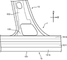
- FIG. 4 is a side view of the connecting portion J viewed from the outside of the vehicle, and shows a state where the side frame outer 100 is removed.
- 6 is an enlarged perspective view of the connecting portion J in the same state as FIG.
- the center pillar outer rain 131 includes an upper end portion 133 joined to the roof rail 11 and a lower end portion 134 joined to the side sill 15 (side sill outer rain 151).
- the lower end portion 134 is a portion whose width in the front-rear direction is wider than the main body portion of the center pillar outer rain 131, and includes a front end edge 134F and a rear end edge 134B at a front end and a rear end of the wide portion.
- the lower end portion 134 is bent in an L shape in a cross section in the vehicle width direction as shown in FIG. 2 so as to have a bulge in the vehicle outer direction.
- the inner surface of the lower end portion 134 is in contact with the outer surface of the side sill outer rain 151 and is fixed to the first side plate 1511 by spot welding.
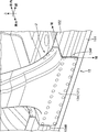
- FIG. 5 is a side view showing a state where the center pillar outer rain 131 has been removed from the state of FIG.
- the center pillar inner 132 is a substantially flat plate-like member extending in the vertical direction, and includes a partition plate portion 135 (partition panel) disposed on the closed cross section of the side sill 15 at the lower end thereof.
- the closed cross section of the side sill 15 is partitioned into a first closed cross section C ⁇ b> 1 and a second closed cross section C ⁇ b> 2 by the partition plate portion 135.
- the first closed cross-section portion C1 is a space defined by the partition plate portion 135 and the side sill inner 152
- the second closed cross-section portion C2 is a space defined by the partition plate portion 135 and the side sill outer train 151.
- the side sill outer rain 151 and the side sill inner 152 are joined to each other with a partition plate part 135 interposed between the butted surfaces.
- the first upper flange portion 1514 and the second upper flange portion 1524 are abutted against each other across the upper end portion of the partition plate portion 135, and are fixed by spot welding.
- the first lower flange portion 1515 and the second lower flange portion 1525 are abutted against each other across the lower end portion of the partition plate portion 135 and are fixed together with the lower end portion 101 of the side frame outer 100 by spot welding.
- the partition plate portion 135 is a portion whose width in the front-rear direction (predetermined direction) is wider than the main body portion of the center pillar inner 132, and the front end and the rear end of the wide portion Are provided with a front edge 135F and a rear edge 135B.
- the closed cross section of the side sill 15 is divided into two closed cross sections C1 and C2 extending in the front-rear direction.
- extending portions 3 functioning as reinforcing bodies that reinforce the rigidity of the side sill 15 extend from the front end edge 135F and the rear end edge 135B, respectively.
- One extension portion 3 is disposed before and after the second closed cross-section portion C2.
- the bulkhead 2 is a reinforcing body that reinforces the rigidity of the side sill 15 in the vicinity of the connecting portion J.
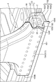
- 7 is a cross-sectional view taken along the line VII-VII of FIG. 6,
- FIG. 8 is a perspective view showing a state where the side sill outer rain 151 is removed from the state of FIG. 5, and
- FIG. 9 is a center pillar from the state of FIG. It is a perspective view which shows the state from which the inner 132 was removed.
- One bulkhead 2 is disposed at the front and back of the first closed section C1.
- the front bulkhead 2 is arranged near the front end edge 135F of the partition plate portion 135, and the rear bulkhead 2 is arranged near the rear end edge 135B. That is, the bulkhead 2 is disposed between the side sill inner 152 and the partition plate portion 135 in the vicinity of the front edge 135F and the rear edge 135B, and has a joint portion for both.
- the extension portion 3 is formed by bending an extra length portion extending in the front-rear direction from the front end edge 135F and the rear end edge 135B to the vehicle outer side, and has a joint portion to the side sill outer rain 151.
- the bulkhead 2 includes a joint portion 21 (panel joint portion) joined to the side sill inner 152 (first panel) and a flange portion 22 joined to the partition plate portion 135 (partition panel).
- the extension part 3 is an integral part of the partition plate part 135, and extends from the front end edge 135 ⁇ / b> F or the rear end edge 135 ⁇ / b> B to the vehicle outer side (side sill outer rain 151), and the end of the extension main body part 31.
- An extended joint portion 32 is formed on the edge and joined to the side sill outer rain 151 (second panel).
- the joining portion formed by the bulkhead 2 includes the damping member 4 between the rigid coupling portion 2A joined in a state where the side sill inner 152 and the joining portion 21 are in contact with each other, and the partition plate portion 135 and the flange portion 22. And a soft coupling portion 2B coupled in a state of being interposed.
- the joint formed by the extension joint 32 of the extension 3 is a rigid joint 3A.
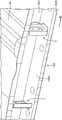
- FIG. 10 is a perspective view of the bulkhead 2
- FIG. 11A is a side view of the bulkhead 2
- FIG. 11B is a top view thereof.
- the bulkhead is also called a node member, and is a member formed by punching and bending a plate material having excellent rigidity such as a steel material.
- the bulkhead 2 includes a reinforcing main body portion 20 that is a substantially trapezoidal flat plate-like portion, and the above-described joint portion 21 and flange portion 22.
- the reinforcing main body portion 20 extends between the joint portion 21 and the flange portion 22.
- four joining pieces that is, a first joining piece 211, a second joining piece 212, a third joining piece 213, and a fourth joining piece 214 are provided as the joining portion 21.
- a first ridge line portion 201 and a second ridge line portion 202 formed by bending are present on the outer peripheral edge of the reinforcing main body portion 20.
- the second ridge line portion 202 is a linear ridge line along the lower bottom side of the trapezoidal reinforcing main body portion 20, and the first ridge line portion 201 is a U-shaped ridge line along the side excluding the lower bottom side.
- the first to fourth joining pieces 211 to 214 are forwardly raised portions connected to the first ridge line portion 201, and each has an independent tongue-like shape.
- the bending angle with respect to the reinforcing main body 20 is approximately 90 °.
- the first to fourth joining pieces 211 to 214 are portions that form the side sill inner 152 and the rigid coupling portion 2A, and have a size that allows spot welding.
- the flange portion 22 is a rearward bending portion provided continuously to the second ridge line portion 202, and similarly, the bending angle with respect to the reinforcing main body portion 20 is approximately 90 °.
- the flange portion 22 is a portion that forms the partition plate portion 135 and the flexible coupling portion 2B, and has a size that can carry the damping member 4 having a sufficient size.
- the flange portion 22 is formed with a step portion 221 extending in the front-rear direction in order to improve the rigidity of the flange portion 22.
- the reinforcing main body portion 20 is a portion that functions as a partition surface portion that partitions the first closed cross-section portion C1 formed by the partition plate portion 135 and the side sill inner 152 in the front-rear direction. That is, the reinforcing main body portion 20 forms a surface extending in a direction substantially orthogonal to the direction in which the first closed cross-section portion C1 extends in the first closed cross-section portion C1. Therefore, by incorporating the bulkhead 2, it is possible to increase resistance to a deformation force that crushes the first closed cross-section portion C ⁇ b> 1, that is, a deformation force that collapses so that the side sill inner 152 and the partition plate portion 135 approach.
- a drawing portion 23 having a shape that is generally similar to the outer shape of the reinforcing main body portion 20 is provided.
- the drawn portion 23 is a flat plate-like portion that protrudes rearward from the peripheral portion 203 in the reinforcing main body portion 20.
- the circular hole 24 and the long hole 25 are holes having various functions. These function firstly as holes for allowing a fluid to flow in the front-rear direction through the arrangement position of the bulkhead 2, and secondly, a processing standard for forming the bulkhead 2 by bending a metal plate. Third, it functions as a positioning reference hole when the bulkhead 2 is assembled into the first closed cross section C1. In the first function, the circular hole 24 and the long hole 25 are used as passage holes for spreading the electrodeposition liquid into the side sill 15 when the vehicle body 1 is electrodeposited with a rust inhibitor. In the second and third functions, for example, the circular hole 24 is used as a fixing hole at the time of processing or positioning, and the long hole 25 is used as an escape hole.
- the reinforcing main body portion 20 functions as a partition surface portion that partitions the first closed cross-section portion C1. For this reason, the reinforcement main-body part 20 will block the closed cross-section part C1 of the side sill 15 extended in the front-back direction.
- One of the manufacturing processes of the vehicle body 1 is a process of electrodepositing a rust preventive agent on the vehicle body 1 after the vehicle body 1 is assembled. In this process, the vehicle body 1 is immersed in an electrodeposition liquid.
- the electrodeposition liquid may not spread well on the inner surface of the side sill 15 (the inner surface of the side sill inner 152 and one side of the partition plate portion 135).
- the electrodeposition liquid can be circulated through the circular holes 24 and the long holes 25, and good electrodeposition coating can be performed.
- the narrowed ridge line portion 26 includes a linear portion 27 along the direction in which the flange portion 22 extends between the flange portion 22 and the circular hole 24 and the long hole 25.
- the narrowed ridge line portion 26 functions as a high-rigidity portion that reinforces the rigidity of the reinforcing main body portion 20 that tends to be fragile by the perforation of the circular hole 24 and the long hole 25.
- the straight portion 27 contributes to increasing the rigidity of the flange portion 22.
- a joining mode of the joining portion 21 forming the rigid coupling portion 2A to the side sill inner 152 will be described with reference to FIG.
- the first joining piece 211 and the second joining piece 212 of the joining portion 21 are brought into contact with the inner surface of the second upper plate 1522 of the side sill inner 152, and are respectively fixed to the second upper plate 1522 by spot welding.
- the third joining piece 213 is brought into contact with the second side plate 1521 and the fourth joining piece 214 is brought into contact with the second lower plate 1523 and fixed by spot welding.
- the flange portion 22 is a portion facing the inner surface of the partition plate portion 135 of the center pillar inner 132. As shown in FIG. 11A, the flange portion 22 of the present embodiment is a rectangle that is long in the vertical direction when viewed from the side, and has a shape that is slightly curved toward the inside of the vehicle as can be seen from FIG. 11B when viewed from the top. is doing.
- the step portion 221 extends linearly in the front-rear direction near the center of the first flange portion 22 in the vertical direction.
- the flange portion 22 has a first surface 22X facing the partition plate portion 135 and a second surface 22Y on the opposite side.
- the first surface 22X serves as a joining region in contact with the damping member 4 in the flexible coupling portion 2B. That is, the first surface 22X is opposed to the inner surface of the partition plate part 135 with a gap of a predetermined distance, and the damping member 4 is interposed in the gap. In other words, the flange portion 22 and the partition plate portion 135 are joined with the attenuation member 4 interposed therebetween.
- the four joint pieces 211 to 214 as the joint portion 21 are spot-welded to the side sill inner 152 as the rigid joint portion 2A.
- the number of joining pieces that is, the number of spot welded portions is an example, and can be appropriately set according to the shape of the side sill inner 152 and the like. Moreover, you may weld the 1st ridgeline part 201 to the side sill inner 152, without forming the joining piece for rigid connection parts.
- the rigid coupling portion 2A can be formed other than by spot welding, and may be a mechanical coupling portion using, for example, a bolt or a nut. In this case, holes for inserting bolts are formed in the first to fourth joining pieces 211 to 214 and the side sill inner 152.
- the rigid coupling portion 2A may be an adhesive portion using an adhesive.
- an adhesive generally used for bonding a vehicle body can be used.
- an adhesive having a storage elastic modulus of 2000 MPa or more and a loss coefficient of 0.05 or less can be suitably used under conditions where the temperature is 20 ° C. and the frequency of the excitation force is 30 Hz.
- the damping member 4 constituting the flexible coupling portion 2B is a member having an ability to attenuate vibrations.
- the damping member 4 is not particularly limited as long as it has a predetermined viscoelasticity.
- a viscoelastic member made of a silicone material or an acrylic material can be used.
- As the physical properties of the viscoelastic member a material having a storage elastic modulus of 500 MPa or less and a loss coefficient of 0.2 or more under the conditions where the temperature is 20 ° C. and the frequency of the excitation force is 30 Hz This is preferable in that transmission can be effectively suppressed.
- the damping member 4 made of such a viscoelastic member absorbs vibration energy as strain energy, converts it into heat energy, and dissipates it to attenuate vibration.
- the method for disposing the damping member 4 on the first surface 22X of the flange portion 22 is not particularly limited.
- a layer to be the attenuation member 4 can be formed by applying a paste-like viscoelastic member to the flange portion 22 by a predetermined thickness. Or you may make it prepare the bulk piece used as the attenuation member 4, and affix this on the flange part 22.
- the flange part 22 may be divided into a plurality of parts like the joint part 21, and in this case, a layer to be the damping member 4 is formed in each of the divided flange parts 22.
- the body 1 is electrodeposited with a rust preventive agent.
- the vehicle body 1 is introduced into a heating furnace, and a drying process is performed in which the vehicle body 1 is heated at a predetermined temperature for a certain period. It is desirable to use the heat of the drying process for fixing the damping member 4. That is, before the electrodeposition coating process, the bulkhead 2 that has previously supported the coating layer to be the damping member 4 is applied to the side sill inner 152 by applying the paste-like viscoelastic member to the flange portion 22 as described above. Make a rigid connection (spot welding). Then, it is desirable that the coating layer is fixed to the partition plate portion 135 using heat applied to the vehicle body 1 in the drying step.
- the bulkhead 2 is disposed so that the reinforcing main body portion 20 becomes the partition surface of the first closed cross-section portion C1, and forms the side sill inner 152 and the rigid coupling portion 2A at the joint portion 21.
- the flexible coupling portion 2 ⁇ / b> B is formed via the partition plate portion 135 of the center pillar inner 132 and the damping member 4.
- the bulkhead 2 has a narrowed ridge portion 26 in the reinforcing main body portion 20 and a step portion 221 in the flange portion 22 in order to increase its rigidity.
- the narrowed ridge portion 26 increases the rigidity of the reinforcing main body portion 20 having the circular hole 24 and the long hole 25 that must be drilled for various reasons.
- the stepped portion 221 increases the rigidity of the strip-shaped flange portion 22 that is long in the vertical direction. Therefore, the rigidity of the bulkhead 2 becomes high, and the reinforcing ability of the first closed cross section C1 can be improved.
- the rigidity difference between the bulkhead 2 and the damping member 4 becomes larger, and when the vehicle body 1 is vibrated, the degree of stress concentration on the damping member 4 is further increased. It is done.
- the rigidity of the bulkhead 2 is low, for example, when the reinforcing main body 20 weakened by the perforation of the circular holes 24 and the long holes 25 is relatively easily bent and deformed, the vibration is applied to the bulkhead 2. Not all vibration stress is transmitted to the damping member 4, and some vibration stress is consumed for the bending deformation. For this reason, the vibration damping effect by the damping member 4 is reduced.
- the bulkhead 2 is made highly rigid in the periphery of the damping member 4 by the diaphragm ridge line portion 26, in particular, the straight portion 27 and the step portion 221, the vibration stress is not lost. Transmission to the damping member 4 is possible. Therefore, the vibration damping effect by the damping member 4 can be further enhanced.
- the extension portion 3 is a portion that is provided integrally with the partition plate portion 135, and is disposed in the second closed cross-section portion C ⁇ b> 2.
- the unit 32 is provided.
- the extension portion 3 extends from the front end edge 135F and the rear end edge 135B. It is a part formed by bending each extra length part extended.
- the extension main body 31 is a flat plate portion bent from the partition plate part 135 extending in the front-rear direction so as to extend from the front end edge 135F or the rear end edge 135B toward the side sill outer rain 151.
- the bending raising angle of the extension main body portion 31 with respect to the partition plate portion 135 is approximately 90 °.
- the extension joint portion 32 is a portion formed by bending the end portion of the extension main body portion 31 on the vehicle outer side by approximately 90 °. In the front extension 3, the extension joint 32 is bent forward, and in the rear extension 3, the extension joint 32 is bent rearward.
- the extension main body 31 is a part that functions as a partition surface part that partitions the second closed cross-sectional part C2 formed by the partition plate part 135 and the side sill outer rain 151 in the front-rear direction. That is, the extension main body 31 has a size corresponding to the cross section of the second closed cross section C2.
- a hole 33 is formed in the extension main body 31. This hole 33 is a hole drilled exclusively for flowing the electrodeposition liquid into the second closed cross-section C2 in the above-described electrodeposition coating process.
- the extended joint portion 32 is a portion that forms the side sill outer rain 151 and the rigid coupling portion 3A.
- the extension joint portion 32 is brought into contact with the bulge portion of the side sill outer rain 151 bulging in the in-car direction of the first side plate 1511 and is fixed to the first side plate 1511 by spot welding.
- another extension joint portion that forms a rigid coupling portion with the first upper plate 1512 and / or the first lower plate 1513 of the side sill outer rain 151 may be extended to the periphery of the extension main body portion 31. good.
- the vehicle inner side edge of the extension main body 31 is continuously connected to the front end edge 135F or the rear end edge 135B of the partition plate part 135. Therefore, the vehicle inner end edge portion can also be regarded as a portion that substantially forms a rigid coupling portion between the extension portion 3 and the partition plate portion 135.
- the extension portion 3 is disposed so that the extension main body portion 31 becomes the partition surface of the second closed cross-section portion C2, and the extension joint portion 32 forms the side sill outer rain 151 and the rigid coupling portion 3A. Further, it can be said that the extension portion 3 is an integral part of the partition plate portion 135 and substantially forms a rigid coupling portion with the partition plate portion 135. By such an extension part 3, the deformation resistance of the second closed cross-section part C2 is enhanced. Therefore, the reinforcement of the second closed cross-section C2 by the extension 3 and the reinforcement of the first closed cross-section C1 by the bulkhead 2 are combined, and the closed cross-section structure with a partition by the partition plate part 135 extending in the front-rear direction. The side sill 15 having the rigidity can be increased.
- the extension portion 3 extends toward the side sill outer rain 151, and the side sill outer rain 151 and the rigid coupling portion 3A. Is forming. For this reason, the stress generated by the vibration of the vehicle is concentrated on the deformable flexible coupling portion 2B, and the vibration is effectively damped by the damping member 4.
- the extension portion 3 includes an extension main body portion 31 extending from the front end edge 135F or the rear end edge 135B toward the side sill outer rain 151, and an extension joint portion 32 at the end edge. For this reason, the extension portion 3 can be easily formed integrally with the partition plate portion 135 by a simple bending process or the like with respect to the partition plate portion 135.
- FIG. 12 is an enlarged view of the front bulkhead 2 and the extension 3 in FIG.
- a characteristic point in the arrangement of the two is that the flat reinforcing main body portion 20 of the bulkhead 2 and the flat extending main body portion 31 of the extension portion 3 are side-sill outer rain as indicated by an arrow L1 in the drawing.
- 151 and the side sill inner 152 are arranged in a straight line in the vehicle width direction.
- the bulkhead 2 and the extension portion 3 are arranged so that the second ridge line portion 202 and the front end edge 135F of the bulkhead 2 face each other in the vehicle width direction with a space for arranging the damping member 4. .
- the flange portion 22 of the bulkhead 2 faces the partition plate portion 135 near the front end edge 135F.
- the reinforcing main body 20 and the extended main body 31 are arranged in a straight line.
- the reinforcing main body 20 and the extended main body 31 may be slightly offset in the front-rear direction.
- the second ridge line portion 202 may be disposed at a position slightly rearward of the front end edge 135F, and as a result, the flexible coupling portion 2B may be formed slightly rearward of the front end edge 135F.
- the mechanical strength of the side sill 15 can be increased by arranging the bulkhead 2 and the extension 3 so that the reinforcing main body 20 and the extension main body 31 are arranged in a straight line.
- the side sill 15 has a closed cross-section structure with a partition including first and second closed cross-section portions C1 and C2 that are partitioned by a partition plate portion 135 and arranged in the vehicle width direction in the connecting portion J.
- this closed cross-sectional structure since the main body portions of the reinforcing main body portion 20 and the extended main body portion 31 are arranged in a straight line, when a pressing force in the vehicle width direction acts on one main body portion, this pressing force Can be directly transmitted to another main body.
- said linear form means that two members (reinforcement main-body part 20 and extension main-body part 31) are arrange
- the reinforcing main body 20 and the extension main body 31 extend so as to be orthogonal to the partition plate 135, respectively. That is, the linear body of the reinforcing main body 20 and the extended main body 31 as indicated by the arrow L1 intersects the partition plate 135 at an intersection angle of about 90 °.
- the mechanical strength in the direction in which the side sill outer rain 151 and the side sill inner 152 approach each other can be further increased.
- the cross-section of the side sill 15 shown in FIG. 2 has a shape (closed sectional structure with a partition) in which two rectangles are arranged in the vehicle width direction.
- the reinforcing main body portion 20 and the extended main body portion 31 further enhance the effect of preventing the cross-section from being deformed into a rhombus shape when a force in the vehicle width direction acts on the side sill 15.
- the above-mentioned orthogonal means that the partition plate portion 135 and the linear bodies of the reinforcing main body portion 20 and the extension main body portion 31 are arranged so as to intersect with each other at an intersection angle of about 80 degrees to 100 degrees. It is not limited to the case where both are arranged at the intersection angle.
- the damping member 4 is disposed at a position where the vibration damping effect can be sufficiently exhibited. That is, since the partition plate portion 135 has ends (the front end edge 135F and the rear end edge 135B) in the closed cross-section portion of the side sill 15, the end portion is a portion where deformation due to vibration is likely to occur. Since the flange portion 22 is joined in the vicinity of the end portion of such a partition plate portion 135, a relatively large strain stress can be applied to the damping member 4, and the vibration damping effect can be enhanced.
- a device for increasing the rigidity difference from the damping member 4 is provided at a portion where the linear bodies of the reinforcing main body portion 20 and the extended main body portion 31 intersect with the partition plate portion 135.
- the flange portion 22 of the bulkhead 2 is formed by bending the edge portion of the reinforcing main body portion 20.
- the narrowed ridge line portion 26 (high rigidity portion) that reinforces the rigidity of the reinforcing main body portion 20 is a stepped portion that is deformed so as to project the reinforcing main body portion 20 in a direction orthogonal to the plane of the reinforcing main body portion 20. It is.
- the bending direction of the flange portion 22 is rearward (frontward in the rear bulkhead 2).
- the protruding direction of the aperture ridge line portion 26 is also rearward (frontward in the rear bulkhead 2). That is, both are in the same direction.
- the cross section is U-shaped as shown by the dotted line figure L2 in FIG. 12 by the straight line portion 27 that is a part of the flange portion 22 and the narrowed ridge line portion 26 and the reinforcing main body portion 20 between them.
- a region will be formed.
- region which the attenuation member 4 adjoins is further improved, and the rigidity difference of the attenuation member 4 and the bulkhead 2 becomes remarkable. Therefore, the strain stress generated by the vibration of the vehicle can be concentrated on the damping member 4, and the vibration damping effect by the damping member 4 can be further enhanced.
- FIG. 13 is a cross-sectional view in the vehicle width direction of the connecting portion between the side sill 15 and the center pillar 13 according to a modified embodiment.
- the bulk head 2 is disposed between the side sill inner 152 and the partition plate part 135, and the extension part 3 extends toward the side sill outer rain 151.
- the modified embodiment of FIG. 13 shows an example in which the extension 3 extends toward the side sill inner 152.
- the bulkhead 2 is disposed between the side sill outer rain 151 and the partition plate portion 135, and the joint portion 21 forms the side sill outer rain 151 and the rigid coupling portion 3A.
- the point in which the flange part 22 forms the partition plate part 135 and the soft coupling part 2B is the same as that of the said embodiment.
- the extension main body portion 31 of the extension portion 3 extends from the front end edge 135F toward the side sill inner 152, and the extension joint portion 32 forms the side sill inner 152 and the rigid coupling portion 3A.
- the side sill outer lane 151 is the first panel in the claims
- the side sill inner 152 is the second panel. Even in such a modified embodiment, the same operational effects as the above-described embodiment can be obtained.
- the present invention may be applied to a connecting portion between the side sill 15 and the front pillar 12.
- a part having a closed cross-sectional structure with a partition which includes two panels (frames) forming a closed cross section extending in a predetermined direction and a partition panel extending in the predetermined direction and disposed in the closed cross section.
- the present invention can be widely applied.
- the vehicle body structure includes a first panel and a second panel that form a closed cross section extending in a predetermined direction, a partition panel extending in the predetermined direction and partitioning the closed cross section, and an inside of the closed cross section. And a reinforcing body that is disposed between the first panel and the partition panel and includes a panel joint portion joined to the first panel and a flange portion joined to the partition panel. In the joint formed by the body, a damping member is interposed between the partition panel and the flange portion, and the rigid joint portion joined in a state where the first panel and the panel joint portion are in contact with each other.
- the partition panel includes an extension portion that extends from the vicinity of the flexible joint portion toward the second panel and is joined to the second panel.
- the reinforcing body is disposed between the first panel and the partition panel in the closed cross section, and the extension extending from the partition panel is between the partition panel and the second panel. Parts are arranged.
- transformation tolerance of the said closed cross-section part can be improved with the said reinforcement body and the said extension part.
- the said reinforcement body forms the rigid coupling
- the joint formed by the extension part with the second panel is preferably a rigid joint part in which a part of the extension part and the second panel are joined in contact with each other.
- the extension portion is a portion extending from the partition panel, and substantially forms a rigid coupling portion with respect to the partition panel. And according to said vehicle body structure, a part of said extension part forms a rigid coupling part with respect to the said 2nd panel. For this reason, the stress generated by the vibration of the vehicle is concentrated on the deformable flexible joint, and the vibration is effectively damped by the damping member.
- the partition panel includes an end portion in the predetermined direction, the flange portion is joined to the partition panel near the end portion, and the extension portion extends from the end portion to the second portion. It is desirable to include an extension main body extending toward the panel, and an extension joint formed at an edge of the extension main body and joined to the second panel.
- the extension portion includes an extension main body portion extending from the end portion toward the second panel and an extension joint portion at an end edge thereof. For this reason, there exists an advantage which can form the said extension part easily with a simple bending process etc. with respect to a partition panel, and can be integrated with a partition panel.
- the extension main body portion is plate-shaped, and the reinforcing body includes a flat plate-shaped reinforcement main body portion extending between the panel joint portion and the flange portion, and the first panel; It is desirable that the reinforcement body and the extension portion are disposed so that the extension main body portion and the reinforcement main body portion are arranged in a straight line between the second panel and the second panel.
- the extension main body portion and the reinforcement main body portion are arranged in a straight line, the mechanical strength of the closed cross-section portion in the direction in which the first panel and the second panel approach each other is increased. Can be increased. Therefore, the deformation resistance of the closed cross section can be further enhanced while exhibiting the vibration damping function.
- the mechanical strength can be further increased by extending the extension main body and the reinforcement main body so as to be orthogonal to the partition panel.
- the first panel is a side sill inner
- the second panel is a side sill outer rain
- the partition panel is a center pillar inner
- the extension portion is joined to the side sill outer rain.
- a vehicle body structure in which a damping member can effectively exhibit a vibration damping function while preventing deformation of the closed cross section portion is provided. be able to. Therefore, the strength of the closed cross section can be increased and the riding comfort of the vehicle can be improved.
Landscapes
- Engineering & Computer Science (AREA)
- Chemical & Material Sciences (AREA)
- Combustion & Propulsion (AREA)
- Transportation (AREA)
- Mechanical Engineering (AREA)
- Body Structure For Vehicles (AREA)
Abstract
車両の車体構造は、所定方向に延びる閉断面部を形成する第1パネル及び第2パネルと、前記所定方向に延び、前記閉断面部を仕切る仕切パネルと、前記閉断面部内において前記第1パネルと前記仕切パネルとの間に配置され、前記第1パネルと接合されるパネル接合部と、前記仕切パネルと接合されるフランジ部とを備える補強体とを備える。前記補強体によって形成される接合部は、前記第1パネルと前記パネル接合部とが互いに当接した状態で結合された剛結合部と、前記仕切パネルとフランジ部との間に減衰部材が介在された状態で結合された柔結合部とを含む。前記仕切パネルは、前記柔結合部の近傍から前記第2パネルに向けて延び、前記第2パネルに接合される延長部を備えている。
Description
本発明は、車両の車体構造に関し、特に閉断面部を形成するパネルと、前記閉断面部内に配設される仕切パネルとを有する部分の車体構造に関する。
自動車等の車両においては、乗員が感じる乗心地を良好なものとするため、車両各部で発生する振動の車室内への伝達を可及的に抑制する車両構造が求められる。この要請を満たすべく本出願人は、特許文献1~3において、閉断面を形成するフレーム内に配設されるバルクヘッド(補強体)の、前記フレームへの接合態様を工夫する技術を提案している。前記接合態様は、前記フレームと前記バルクヘッドとが互いに当接した状態で結合された剛結合部と、前記フレームと前記バルクヘッドとの間に減衰部材が介在された状態で結合された柔結合部とを具備させるというものである。
車両には、所定方向に延びる閉断面を形成する2つのパネル(フレーム)と、前記所定方向に延び前記閉断面内に配設される仕切パネルとを備えた、仕切付き閉断面構造を有する部分が存在する。特許文献3には、このような仕切付き閉断面構造を有する部分に、前記剛結合部と前記柔結合部とを備えたバルクヘッドを組み込んでなる車体構造が開示されている。
上記の仕切付き閉断面構造は、例えばセンターピラーとサイドシルとの連結部などに採用されている。このような連結部は、車両の振動によって生じる閉断面部分の変形や振動の抑制の要請が特に高い。
本発明の目的は、仕切付き閉断面構造の車体部分において、閉断面部分の変形を防止しつつ、減衰部材が効果的に振動の減衰機能を発揮することができる車体構造を提供することにある。
本発明の一局面に係る車両の車体構造は、所定方向に延びる閉断面部を形成する第1パネル及び第2パネルと、前記所定方向に延び、前記閉断面部を仕切る仕切パネルと、前記閉断面部内において前記第1パネルと前記仕切パネルとの間に配置され、前記第1パネルと接合されるパネル接合部と、前記仕切パネルと接合されるフランジ部とを備える補強体と、を備え、前記補強体によって形成される接合部は、前記第1パネルと前記パネル接合部とが互いに当接した状態で結合された剛結合部と、前記仕切パネルとフランジ部との間に減衰部材が介在された状態で結合された柔結合部とを含み、前記仕切パネルは、前記柔結合部の近傍から前記第2パネルに向けて延び、前記第2パネルに接合される延長部を備えていることを特徴とする。
以下、図面に基づいて、本発明の実施形態につき詳細に説明する。
[車体の全体的な説明]
図1は、本発明が適用される車両の車体1の一部を示す斜視図である。図中には、車両の前方を示す「前」の矢印と、後方を示す「後」の矢印を付記している。以下の図に付している「前」「後」などの矢印は、図1に示す車両の前後に相当する。
図1は、本発明が適用される車両の車体1の一部を示す斜視図である。図中には、車両の前方を示す「前」の矢印と、後方を示す「後」の矢印を付記している。以下の図に付している「前」「後」などの矢印は、図1に示す車両の前後に相当する。
車体1は、車両の左右側面を構成するサイドフレーム10を含む。図1では、一方の側面のサイドフレーム10だけを図示している。サイドフレーム10は、車両の側面部分の外装となるサイドフレームアウタ100と、このサイドフレームアウタ100の車内側に配置されたルーフレール11、フロントピラー12、センターピラー13、リアピラー14、及びサイドシル15とを備える。
サイドフレームアウタ100は、プレス成型にて、一枚の鋼鈑を所定形状に成型すると共に前後のドア開口を打ち抜くことによって形成された板材である。サイドフレームアウタ100の外表面は、車両の外装塗装面となる。ルーフレール11は車両の上部において、サイドシル15は車両の下部において、それぞれ車両の前後方向に延びている。ルーフレール11とサイドシル15との間は、前側においてはフロントピラー12で、後側においてはリアピラー14で、そして前後方向の中央付近においてはセンターピラー13で、各々上下方向に連結されている。
前後方向(所定方向)に延びるサイドシル15と、上下方向に延びるセンターピラー13とは、センターピラー13の下端部がサイドシル15の前後方向中間部分に連結される態様の、略T字状に交差する連結部Jを形成している。本実施形態では、この連結部Jに本発明に係る車体構造が適用される例を示す。
一方のサイドフレーム10のルーフレール11と他方のサイドフレームのルーフレール(図略)との間には、車幅方向に延びる複数のレインフォースメント(以下、本明細書では単に「レイン」と言う)及びヘッダが架設される。本実施形態では、センターピラー13の配設位置に、ルーフレイン16が架設され、その前後に3つのルーフレイン173、174、175が架設されている。さらに、車両の前側にはフロントヘッダ171が、後側にはリアヘッダ172が各々架設されている。これらルーフレイン173~175及びヘッダ171、172の上を覆うように、図略のルーフパネルが、一対のサイドフレーム10間に取り付けられる。また、一方のサイドシル15と他方のサイドシル(図略)との間には、複数のクロスメンバが架設される。図1では、連結部Jに架設されるクロスメンバ18だけを示している。
[連結部Jの構造]
図2は、図1のII-II線の概略的な断面図、図3は、サイドシル15とセンターピラー13との連結部Jの、車幅方向の断面図である。連結部Jの車外側はサイドフレームアウタ100で覆われている。連結部Jの車内側、つまり車室の底部は、フロアパネル102で覆われている。フロアパネル102の上には、上述のクロスメンバ18及びその構成部材であるシートブラケット103が配置されている。また、連結部Jにおけるサイドシル15の閉断面部内には、バルクヘッド2(補強体)と、センターピラー13の構成部材と一体の延長部3が配設されている。以下、各部材を説明する。
図2は、図1のII-II線の概略的な断面図、図3は、サイドシル15とセンターピラー13との連結部Jの、車幅方向の断面図である。連結部Jの車外側はサイドフレームアウタ100で覆われている。連結部Jの車内側、つまり車室の底部は、フロアパネル102で覆われている。フロアパネル102の上には、上述のクロスメンバ18及びその構成部材であるシートブラケット103が配置されている。また、連結部Jにおけるサイドシル15の閉断面部内には、バルクヘッド2(補強体)と、センターピラー13の構成部材と一体の延長部3が配設されている。以下、各部材を説明する。
サイドシル15は、前後方向(所定方向)に延びる閉断面部を有する車体剛性部材であり、断面形状が略コ字型のサイドシルアウタレイン151(第2パネル)と、同じく断面形状が略コ字型のサイドシルインナ152(第1パネル)とからなる。サイドシルアウタレイン151は、前記コ字型形状の開口部分と略平行な第1側板1511と、この第1側板1511の上縁及び下縁から各々車内方向に延びる第1上板1512及び第1下板1513とを含む。他の部材との接合を行うため、第1上板1512の開口側端縁には第1上フランジ部1514が、第1下板1512の開口側端縁には第1下フランジ部1515が、各々設けられている。
サイドシルインナ152は、前記コ字型形状の開口部分と略平行な第2側板1521と、この第2側板1521の上縁及び下縁から各々車外方向に延びる第2上板1522及び第2下板1523とを含む。他の部材との接合を行うため、第2上板1522の開口側端縁には第2上フランジ部1524が、第2下板1522の開口側端縁には第2下フランジ部1525が、各々設けられている。
センターピラー13は、上下方向に延びる閉断面を有する車体剛性部材であり、車外側のセンターピラーアウタレイン131と、車内側のセンターピラーインナ132とからなる。センターピラーアウタレイン131及びセンターピラーインナ132は、共に前後方向の端部に突合せ接合用のフランジ部を有し、スポット溶接にて前記フランジ部同士を接合することによって、両者は一体化されている。
図4は、車両の車外側から連結部Jを見た側面図であって、サイドフレームアウタ100が取り除かれた状態を示す図である。図6は、図4と同じ状態の、連結部Jの拡大斜視図である。センターピラーアウタレイン131は、ルーフレール11に接合される上端部133と、サイドシル15(サイドシルアウタレイン151)に接合される下端部134とを備える。下端部134は、センターピラーアウタレイン131の本体部分よりも前後方向の幅が幅広とされた部分であり、その幅広部分の前端及び後端に、前端縁134F及び後端縁134Bを備える。また、下端部134は、車外方向に膨らみを持つよう、図2に示す通り車幅方向の断面においてL字型に折り曲げられている。下端部134の内面はサイドシルアウタレイン151の外面に当接しており、第1側板1511にスポット溶接にて固着されている。
図5は、図4の状態から、センターピラーアウタレイン131が取り除かれた状態を示す側面図である。センターピラーインナ132は、上下方向に延びる、概ね平板状の部材であり、その下端に、サイドシル15の閉断面部に配設される仕切板部135(仕切パネル)を備えている。図2に示す通り、仕切板部135によってサイドシル15の閉断面部は、第1閉断面部C1と第2閉断面部C2とに仕切られている。第1閉断面部C1は、仕切板部135とサイドシルインナ152とによって区画された空間、第2閉断面部C2は、仕切板部135とサイドシルアウタレイン151とによって区画された空間である。
サイドシルアウタレイン151とサイドシルインナ152とは、その突合せ面部分に仕切板部135を介在させて、互いに接合されている。詳しくは、第1上フランジ部1514と第2上フランジ部1524とは、仕切板部135の上端部分を挟んで互いに突き合わされ、スポット溶接にて固着されている。また、第1下フランジ部1515と第2下フランジ部1525とは、仕切板部135の下端部分を挟んで互いに突き合わされ、サイドフレームアウタ100の下端部分101と共にスポット溶接にて固着されている。
仕切板部135は、図8に示されているように、センターピラーインナ132の本体部分よりも前後方向(所定方向)の幅が幅広とされた部分であり、その幅広部分の前端及び後端に、前端縁135F及び後端縁135Bを備える。この前端縁135Fから後端縁135Bまでの範囲において、サイドシル15の閉断面部は前後方向に延びる2つの閉断面部C1、C2に分割されている。また、前端縁135F及び後端縁135Bからは、サイドシル15の剛性を補強する補強体として機能する延長部3がそれぞれ延設されている。延長部3は、第2閉断面部C2の前後に1個ずつ配設されている。
バルクヘッド2は、連結部Jの近傍においてサイドシル15の剛性を補強する補強体である。図7は、図6のVII-VII線断面図、図8は、図5の状態から、サイドシルアウタレイン151が取り除かれた状態を示す斜視図、図9は、図8の状態から、センターピラーインナ132が取り除かれた状態を示す斜視図である。バルクヘッド2は第1閉断面部C1に前後1個ずつ配設されている。
前側のバルクヘッド2は、仕切板部135の前端縁135F付近に配置され、後側のバルクヘッド2は、後端縁135B付近に配置されている。すなわち、バルクヘッド2は、前端縁135F及び後端縁135B付近において、サイドシルインナ152と仕切板部135との間に配置され、両者に対する接合部を有している。延長部3は、前端縁135F及び後端縁135Bから前後方向に延び出した余長部分を車外側へ折り曲げて形成されており、サイドシルアウタレイン151に対する接合部を有している。
バルクヘッド2は、サイドシルインナ152(第1パネル)と接合される接合部21(パネル接合部)と、仕切板部135(仕切パネル)と接合されるフランジ部22とを備えている。延長部3は、仕切板部135と一体の部分であり、前端縁135F又は後端縁135Bから車外側(サイドシルアウタレイン151)に延び出している延長本体部31と、延長本体部31の端縁に形成され、サイドシルアウタレイン151(第2パネル)と接合される延長接合部32とを備えている。
バルクヘッド2によって形成される接合部は、サイドシルインナ152と接合部21とが互いに当接した状態で結合された剛結合部2Aと、仕切板部135とフランジ部22との間に減衰部材4が介在された状態で結合された柔結合部2Bとを含む。一方、延長部3の延長接合部32によって形成される接合部は剛結合部3Aである。
[バルクヘッドの詳細説明]
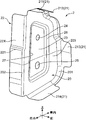
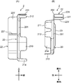
続いて、バルクヘッド2について詳述する。図10は、バルクヘッド2の斜視図、図11(A)はバルクヘッド2の側面図、図11(B)はその上面図である。バルクヘッドは、節部材とも呼ばれ、鋼材等の優れた剛性を有する板材に、打ち抜き及び折り曲げ加工等を施して形成された部材である。
続いて、バルクヘッド2について詳述する。図10は、バルクヘッド2の斜視図、図11(A)はバルクヘッド2の側面図、図11(B)はその上面図である。バルクヘッドは、節部材とも呼ばれ、鋼材等の優れた剛性を有する板材に、打ち抜き及び折り曲げ加工等を施して形成された部材である。
バルクヘッド2は、概ね台形の平板状部分からなる補強本体部20と、上述の接合部21及びフランジ部22とを備える。補強本体部20は、接合部21とフランジ部22との間に延在している。ここでは、接合部21として4つの接合片、すなわち第1接合片211、第2接合片212、第3接合片213及び第4接合片214が備えられている。補強本体部20の外周縁には、折り曲げ加工によって形成された第1稜線部201及び第2稜線部202が存在する。第2稜線部202は、台形形状の補強本体部20の下底辺に沿う直線状の稜線であり、第1稜線部201は前記下底辺を除く辺に沿うコ字型の稜線である。
第1~第4接合片211~214は、第1稜線部201に連設された前方への曲げ起こし部分であり、各々が独立した舌片状の形状有している。これらの、補強本体部20に対する曲げ起こし角は略90°である。第1~第4接合片211~214は、サイドシルインナ152と剛結合部2Aを形成する部分であり、スポット溶接を行い得るサイズを有している。フランジ部22は、第2稜線部202に連設された後方への曲げ起こし部分であり、同様に補強本体部20に対する曲げ起こし角は略90°である。フランジ部22は、仕切板部135と柔結合部2Bを形成する部分であり、十分なサイズの減衰部材4を担持し得るサイズを有している。なお、フランジ部22には、当該フランジ部22の剛性を向上させるため、前後方向に延びる段差部221が形成されている。
補強本体部20は、仕切板部135とサイドシルインナ152とによって作られる第1閉断面部C1を、前後方向に仕切る仕切面部として機能する部分である。すなわち、補強本体部20は、第1閉断面部C1が延びる方向に対して概ね直交する方向に延びる面を、当該第1閉断面部C1内において形成する。従って、バルクヘッド2の組込によって、第1閉断面部C1を圧潰させる変形力、すなわちサイドシルインナ152と仕切板部135とが接近するように潰れる変形力に対する耐性を高めることができる。
補強本体部20の中央には、概ね補強本体部20の外形形状と相似の形状を備えた絞り加工部23が備えられている。絞り加工部23は、補強本体部20において、周辺部203よりも後方に突出した平板状の部分である。絞り加工部23には、前後方向に貫通する2つの孔である円形孔24と長孔25とが、上下方向に並んで穿孔されている。
円形孔24及び長孔25は、種々の機能を持つ孔である。これらは、第1に、バルクヘッド2の配置位置を通して前後方向に流体を良好に流通させるための孔として機能し、第2に、バルクヘッド2を金属板の折り曲げ加工により形成する際の加工基準孔として機能し、第3に、バルクヘッド2を第1閉断面部C1内に組み付けるに際しての位置決め基準孔として機能する。前記第1の機能において、円形孔24及び長孔25は、専ら車体1に防錆剤を電着塗装する際に、サイドシル15内に電着液を行き渡らせるための通過孔として利用される。前記第2、第3の機能においては、例えば円形孔24は加工又は位置決めの際の固定孔として、長孔25は逃がし孔として利用される。
前記第1の機能について説明を加える。補強本体部20は、既述の通り第1閉断面部C1を仕切る仕切面部として機能する。このため、前後方向に延びるサイドシル15の閉断面部C1を、補強本体部20は塞ぐことになる。車体1の製造工程の一つに、車体1の組み立て後に該車体1に防錆剤を電着塗装する工程があり、該工程においては車体1が電着液に浸漬される。ここで、補強本体部20が第1閉断面部C1を塞いでいると、電着液がサイドシル15の内面(サイドシルインナ152の内面及び仕切板部135の片面)に良好に行き渡らない場合がある。円形孔24及び長孔25の形成により、前記電着液は円形孔24及び長孔25を通して流通できるようになり、良好な電着塗装が行うことができる。
補強本体部20の周辺部203と絞り加工部23との境界には、絞り加工により形成される絞り稜線部26が形成されている。絞り稜線部26は、フランジ部22と円形孔24及び長孔25との間において、フランジ部22が延在する方向に沿う直線部分27を含む。絞り稜線部26は、円形孔24及び長孔25の穿孔によって脆弱となりがちな補強本体部20の剛性を補強する、高剛性部として機能する。とりわけ、直線部分27は、フランジ部22の剛性を高めることに貢献する。
剛結合部2Aを形成する接合部21の、サイドシルインナ152への接合態様について、図2も参照して説明する。接合部21の第1接合片211及び第2接合片212は、サイドシルインナ152の第2上板1522の内面に当接され、それぞれスポット溶接によって当該第2上板1522に固着される。第3接合片213は第2側板1521に、また第4接合片214は第2下板1523にそれぞれ当接され、スポット溶接にて固着される。
フランジ部22は、センターピラーインナ132の仕切板部135の、車内側の面と対向する部分である。本実施形態のフランジ部22は、図11(A)に示すように側面視で上下方向に長い長方形であり、上面視の図11(B)から判る通り、やや車内側に湾曲した形状を有している。段差部221は、第1フランジ部22の上下方向の中央付近において、前後方向へ直線状に延びている。
フランジ部22は、仕切板部135に対向する第1面22Xと、その反対側の第2面22Yとを有する。第1面22Xは、柔結合部2Bにおいて減衰部材4に接する接合領域となる。つまり、第1面22Xは、仕切板部135の車内側の面に対して所定距離の隙間を置いて対向し、前記隙間に減衰部材4が介在される。換言すると、フランジ部22と仕切板部135とは、減衰部材4を挟んで接合される。
本実施形態では、上記の通り剛結合部2Aとして、接合部21としての4つの接合片211~214をサイドシルインナ152にスポット溶接する態様を例示している。接合片の個数、すなわちスポット溶接箇所の数は一例であり、サイドシルインナ152の形状等に応じて適宜設定することができる。また、剛結合部用の接合片を形成することなく、第1稜線部201をサイドシルインナ152に溶接しても良い。
剛結合部2Aは、スポット溶接に以外でも形成可能であり、例えばボルト、ナット等を用いた機械的な結合部であってもよい。この場合、第1~第4接合片211~214及びサイドシルインナ152には、ボルト挿通用の孔が穿孔される。あるいは、剛結合部2Aは、接着剤による接着部であってもよい。この場合、前記接着剤としては、一般的に車体の接着用に使用されている接着剤を用いることができる。例えば、温度が20℃、かつ加振力の周波数が30Hzである条件下において、貯蔵弾性率が2000MPa以上で、かつ、損失係数が0.05以下である接着剤を好適に用いることができる。
柔結合部2Bを構成する減衰部材4は、振動を減衰させる能力を有する部材である。減衰部材4は、所定の粘弾性を有する部材であれば特に限定はなく、例えば、シリコーン系材料またはアクリル系材料からなる粘弾性部材を使用することができる。粘弾性部材の物性としては、温度が20℃、かつ加振力の周波数が30Hzである条件下において、貯蔵弾性率が500MPa以下で、かつ、損失係数が0.2以上のものが、振動の伝達を効果的に抑制できる点で好ましい。このような粘弾性部材からなる減衰部材4は、振動エネルギーをひずみエネルギーとして吸収し、これを熱エネルギーに変換して散逸することにより、振動を減衰する。
フランジ部22の第1面22Xへ減衰部材4を配設する方法は、特に限定はない。例えば、ペースト状の粘弾性部材をフランジ部22に所定厚さだけ塗布することにより、減衰部材4となる層を形成することができる。あるいは、減衰部材4となるバルク片を準備し、これをフランジ部22に貼り付けるようにしても良い。なお、フランジ部22は、接合部21のように複数に分割されたものであっても良く、この場合、分割されたフランジ部22の各々に減衰部材4となる層が形成される。
上述の通り、車体1には防錆剤が電着塗装される。電着塗装工程の後、防錆剤層を乾燥させるために、車体1が加熱炉内に導入され、車体1が所定の温度で一定期間だけ加熱する乾燥工程が実行される。この乾燥工程の熱を、減衰部材4の固着に用いることが望ましい。すなわち、電着塗装工程の前に、上述の通りペースト状の粘弾性部材をフランジ部22に塗布することによって、減衰部材4となる塗布層を予め担持させたバルクヘッド2を、サイドシルインナ152に剛結合(スポット溶接)しておく。そして、前記乾燥工程において車体1に与えられる熱を利用して、前記塗布層を仕切板部135に固着させることが望ましい。
以上の通り、バルクヘッド2は、補強本体部20が第1閉断面部C1の仕切り面となるように配設され、その接合部21においてサイドシルインナ152と剛結合部2Aを形成し、また、フランジ部22においてセンターピラーインナ132の仕切板部135と、減衰部材4を介して柔結合部2Bを形成する。これにより、第1閉断面部C1の変形耐性は高められ、サイドシル15の剛性は向上する。また、車両の振動により発生した応力は、変形可能な柔結合部2Bに集中するようになり、減衰部材4によって振動が減衰される。
また、バルクヘッド2は、自身の剛性を高めるために、補強本体部20に絞り稜線部26を、フランジ部22に段差部221を、それぞれ有している。絞り稜線部26は、種々の理由で穿孔せねばならない円形孔24及び長孔25を有する補強本体部20の剛性を高める。段差部221は、上下方向に長い帯状のフランジ部22の剛性を高める。従って、バルクヘッド2の剛性は高いものとなり、第1閉断面部C1の補強能力を向上することができる。
さらに、バルクヘッド2の高剛性化を図ることによって、バルクヘッド2と減衰部材4との剛性差がより大きくなり、車体1に振動が発生したときに、減衰部材4に対する応力集中度合いが一層高められる。バルクヘッド2の剛性が低い場合、例えば円形孔24及び長孔25の穿孔によって脆弱化した補強本体部20が比較的容易に曲げ変形してしまうような場合、バルクヘッド2に振動が加わった時に減衰部材4へ全ての振動応力が伝達されず、一部の振動応力が前記曲げ変形に消費されてしまう。このため、減衰部材4による振動減衰効果が低下する。これに対し本実施形態では、絞り稜線部26、とりわけ直線部分27と、段差部221とによって、減衰部材4の周辺においてバルクヘッド2の高剛性化が図られているので、振動応力をロスなく減衰部材4へ伝達することが可能となる。従って、減衰部材4による振動減衰効果をより高めることができる。
[延長部の詳細説明]
続いて、延長部3について説明する。図3、図7、図8に示す通り、延長部3は、仕切板部135に一体的に備えられた部分であり、第2閉断面部C2に配設され、延長本体部31及び延長接合部32を備える。延長部3は、センターピラーインナ132の仕切板部135が本来必要な前後方向の長さ(前端縁135Fから後端縁135Bまでの長さ)に加えて、前端縁135F及び後端縁135Bから各々延設された余長部分に、折り曲げ加工を施すことによって形成された部分である。
続いて、延長部3について説明する。図3、図7、図8に示す通り、延長部3は、仕切板部135に一体的に備えられた部分であり、第2閉断面部C2に配設され、延長本体部31及び延長接合部32を備える。延長部3は、センターピラーインナ132の仕切板部135が本来必要な前後方向の長さ(前端縁135Fから後端縁135Bまでの長さ)に加えて、前端縁135F及び後端縁135Bから各々延設された余長部分に、折り曲げ加工を施すことによって形成された部分である。
延長本体部31は、前端縁135F又は後端縁135Bからサイドシルアウタレイン151に向けて延びるよう、前後方向に延びる仕切板部135から曲げ起こされた平板状の部分である。延長本体部31の仕切板部135に対する曲げ起こし角は略90°である。延長接合部32は、延長本体部31の車外側の端縁部分を略90°折り曲げることによって形成された部分である。前側の延長部3においては、延長接合部32は前側に折り曲げられ、後側の延長部3においては、延長接合部32は後側に折り曲げられている。
延長本体部31は、仕切板部135とサイドシルアウタレイン151とによって作られる第2閉断面部C2を、前後方向に仕切る仕切面部として機能する部分である。つまり、延長本体部31は、第2閉断面部C2の断面に応じたサイズを有している。また、延長本体部31には孔33が穿孔されている。この孔33は、専ら上述の電着塗装工程において電着液を第2閉断面部C2内に流通させるために穿孔された孔である。
延長接合部32は、サイドシルアウタレイン151と剛結合部3Aを形成する部分である。延長接合部32は、サイドシルアウタレイン151の第1側板1511における車内方向に膨出したバルジ部に当接され、スポット溶接によって当該第1側板1511に固着される。なお、サイドシルアウタレイン151の第1上板1512及び/又は第1下板1513に対して剛結合部を形成する他の延長接合部を、延長本体部31の周縁に延設するようにしても良い。なお、延長本体部31の車内側端縁は、仕切板部135の前端縁135F又は後端縁135Bに連続的に繋がっている。それゆえ、前記車内側端縁の部分も、実質的に延長部3と仕切板部135との剛結合部を形成する部分であると見なすことができる。
以上の通り、延長部3は、延長本体部31が第2閉断面部C2の仕切り面となるように配設され、延長接合部32がサイドシルアウタレイン151と剛結合部3Aを形成する。また、延長部3は仕切板部135と一体の部分であり、実質的に仕切板部135と剛結合部を形成していると言える。このような延長部3により、第2閉断面部C2の変形耐性が高められる。従って、この延長部3による第2閉断面部C2の補強と、バルクヘッド2による第1閉断面部C1の補強とが相俟って、前後方向に延びる仕切板部135による仕切付き閉断面構造を有するサイドシル15の剛性は高められる。
また、バルクヘッド2が形成する柔結合部2Bの近傍(前端縁135F又は後端縁135B)において、延長部3はサイドシルアウタレイン151に向けて延び出し、当該サイドシルアウタレイン151と剛結合部3Aを形成している。このため、車両の振動により発生した応力は、変形可能な柔結合部2Bに集中するようになり、減衰部材4によって前記振動が効果的に減衰される。
また、延長部3は、前端縁135F又は後端縁135Bからサイドシルアウタレイン151に向けて延びる延長本体部31と、その端縁の延長接合部32とからなる。このため、当該延長部3を、仕切板部135に対する簡易な折り曲げ加工等により容易に、また仕切板部135と一体的に形成することができる。
[バルクヘッド及び延長部の配置に関する説明]
続いて、バルクヘッド2と延長部3との配置関係に関して説明する。図12は、図3の前側のバルクヘッド2及び延長部3を拡大して示した図である。両者の配置において特徴的な点は、バルクヘッド2の平板状の補強本体部20と、延長部3の平板状の延長本体部31とが、図中の矢印L1で示すように、サイドシルアウタレイン151とサイドシルインナ152との間において車幅方向に直線状に並んでいる点である。
続いて、バルクヘッド2と延長部3との配置関係に関して説明する。図12は、図3の前側のバルクヘッド2及び延長部3を拡大して示した図である。両者の配置において特徴的な点は、バルクヘッド2の平板状の補強本体部20と、延長部3の平板状の延長本体部31とが、図中の矢印L1で示すように、サイドシルアウタレイン151とサイドシルインナ152との間において車幅方向に直線状に並んでいる点である。
詳しくは、バルクヘッド2の第2稜線部202と前端縁135Fとが、減衰部材4の配置スペースを空けて、車幅方向において対峙するよう、バルクヘッド2と延長部3とが配置されている。バルクヘッド2のフランジ部22は、前端縁135F付近の仕切板部135と対向している。このような両者の配置によって、補強本体部20と延長本体部31とが直線状に並ぶようになっている。なお、補強本体部20と延長本体部31とは、若干前後方向にオフセットしていても良い。例えば、第2稜線部202が、前端縁135Fよりもやや後方の位置に配置され、結果として柔結合部2Bが前端縁135Fよりも少々後方に形成される態様であっても良い。
補強本体部20と延長本体部31とが直線状に並ぶようにバルクヘッド2と延長部3とが配設されることによって、サイドシル15の機械的な強度を高めることができる。サイドシル15は、連結部Jにおいて、仕切板部135にて仕切られた、車幅方向に並ぶ第1、第2閉断面部C1、C2を備えた仕切付き閉断面構造を有する。この閉断面構造において、補強本体部20と延長本体部31との両本体部が直線状に並んでいるので、一方の本体部に対して車幅方向の押圧力が作用した場合、この押圧力をダイレクトに他の本体部へ伝達することができる。従って、サイドシルアウタレイン151とサイドシルインナ152とが互いに接近する方向に対する機械的な強度、すなわち車体1の側面衝突に対する変形耐性を、一層高めることができる。なお、上記の直線状とは、直線もしくは直線に近似した線に沿って2つの部材(補強本体部20と延長本体部31)が配置されることをいい、前記2つの部材が完全な直線に沿って配置される場合に限定されない。
さらに、本実施形態では、補強本体部20及び延長本体部31は、それぞれ仕切板部135に対して直交するように延在している。つまり、矢印L1で示す如き補強本体部20及び延長本体部31の直線体が、交差角=約90°で仕切板部135と交差している。これにより、サイドシルアウタレイン151とサイドシルインナ152とが互いに接近する方向に対する機械的な強度を、より一層高めることができる。例えば、図2に示すサイドシル15の断面は、概ね長方形が車幅方向に2つ並ぶ形状(仕切付き閉断面構造)である。この断面が、車幅方向の力がサイドシル15に作用したときに、菱形形状に変形してしまうことを抑止する効果を、補強本体部20及び延長本体部31は一層高める。なお、上記の直交とは、仕切板部135と補強本体部20及び延長本体部31の直線体とが、80度~100度程度の交差角で交差して配置されることをいい、90度の交差角で両者が配置される場合に限定されない。
上記の結果として、減衰部材4はその振動減衰効果を十分に発揮できる位置に配置されている。すなわち、仕切板部135は、サイドシル15の閉断面部内において端部(前端縁135F及び後端縁135B)を持っているので、当該端部は振動に基づく変形が発生し易い部分となる。このような仕切板部135の端部付近にフランジ部22が接合されているので、比較的大きな歪み応力を減衰部材4に与えることができ、振動減衰効果を高めることができる。
加えて、補強本体部20及び延長本体部31の直線体が仕切板部135と交差する部分において、減衰部材4との剛性差を高める工夫が施されている。バルクヘッド2のフランジ部22は、補強本体部20の端縁部分の折り曲げにより形成されている。また、補強本体部20の剛性を補強する絞り稜線部26(高剛性部)は、補強本体部20の平面に対して直交する方向に、該補強本体部20を突出させるよう変形させた段差部である。フランジ部22の折り曲げ方向は、後方(後側のバルクヘッド2では前方)である。絞り稜線部26の突出方向も、後方(後側のバルクヘッド2では前方)である。つまり、両者は同じ方向である。
これにより、フランジ部22及び絞り稜線部26の一部である直線部分27と、これらの間の補強本体部20とによって、図12において符号L2で示す点線図形の通り、断面がコ字型の領域が形成されることになる。このため、減衰部材4が隣接する領域の剛性がより一層高められ、減衰部材4とバルクヘッド2との剛性差が顕著となる。従って、車両の振動により発生する歪み応力を減衰部材4に集中させることができ、当該減衰部材4による振動減衰効果をより高めることができる。
[変形実施形態の説明]
以上、本発明の実施形態を説明したが、本発明はこれに限定されるものではなく、さらに次のような変形実施形態を取ることができる。
以上、本発明の実施形態を説明したが、本発明はこれに限定されるものではなく、さらに次のような変形実施形態を取ることができる。
(1)図13は、変形実施形態に係るサイドシル15とセンターピラー13との連結部の、車幅方向の断面図である。上記実施形態では、バルクヘッド2がサイドシルインナ152と仕切板部135との間に配置され、延長部3がサイドシルアウタレイン151に向けて延びている例を示した。これに対し、図13の変形実施形態では、延長部3がサイドシルインナ152に向けて延びている例を示している。
バルクヘッド2はサイドシルアウタレイン151と仕切板部135との間に配置され、その接合部21はサイドシルアウタレイン151と剛結合部3Aを形成している。フランジ部22が、仕切板部135と柔結合部2Bを形成している点は、上記実施形態と同じである。延長部3の延長本体部31は、前端縁135Fからサイドシルインナ152に向けて延び、延長接合部32はサイドシルインナ152と剛結合部3Aを形成している。当該変形実施形態では、サイドシルアウタレイン151が特許請求の範囲における第1パネル、サイドシルインナ152が第2パネルとなる。このような変形実施形態によっても、上記実施形態と同じ作用効果を奏する。
(2)上記実施形態では、延長部3の延長接合部32が、サイドシルアウタレイン151と剛結合部3Aを形成する例を示した。これに代えて、延長接合部32が柔結合部を形成するものであっても良い。この場合、延長接合部32とサイドシルアウタレイン151との間に減衰部材4が介在される。この変形実施形態によれば、バルクヘッド2のフランジ部22と仕切板部135との間に加えて、延長接合部32とサイドシルアウタレイン151との間にも減衰部材4が配置されるので、振動減衰効果を高めることができる。
(3)上記実施形態では、サイドシル15とセンターピラー13との連結部Jに、本発明に係る車体構造が適用される例を示した。これは一例であり、例えば、サイドシル15とフロントピラー12との連結部に本発明を適用しても良い。この他、所定方向に延びる閉断面を形成する2つのパネル(フレーム)と、前記所定方向に延び前記閉断面内に配設される仕切パネルとを備えた、仕切付き閉断面構造を有する部分に、本発明を広く適用することができる。
最後に、上記実施形態の中で開示された特徴的な構成およびそれに基づく作用効果についてまとめて説明する。
上記実施形態に係る車両の車体構造は、所定方向に延びる閉断面部を形成する第1パネル及び第2パネルと、前記所定方向に延び、前記閉断面部を仕切る仕切パネルと、前記閉断面部内において前記第1パネルと前記仕切パネルとの間に配置され、前記第1パネルと接合されるパネル接合部と、前記仕切パネルと接合されるフランジ部とを備える補強体と、を備え、前記補強体によって形成される接合部は、前記第1パネルと前記パネル接合部とが互いに当接した状態で結合された剛結合部と、前記仕切パネルとフランジ部との間に減衰部材が介在された状態で結合された柔結合部とを含み、前記仕切パネルは、前記柔結合部の近傍から前記第2パネルに向けて延び、前記第2パネルに接合される延長部を備えていることを特徴とする。
この車体構造によれば、閉断面部内において、第1パネルと仕切パネルとの間には補強体が配置されると共に、前記仕切パネルと第2パネルとの間には当該仕切パネルから延び出す延長部が配置される。これにより、前記閉断面部の変形耐性を前記補強体及び前記延長部によって高めることができる。また、前記補強体は、第1パネルとの剛結合部と、仕切パネルとの柔結合部とを形成している。従って、前記柔結合部に配置される減衰部材によって、車体の振動を効果的に減衰させることができる。
上記の車体構造において、前記延長部が前記第2パネルと形成する接合は、前記延長部の一部と前記第2パネルとが互いに当接した状態で結合された剛結合部であることが望ましい。
前記延長部は、前記仕切パネルから延び出した部分であり、当該仕切パネルに対しては、実質的に剛結合部を形成している。そして、上記の車体構造によれば、前記第2パネルに対して前記延長部の一部が剛結合部を形成する。このため、車両の振動により発生した応力は、変形可能な柔結合部に集中するようになり、減衰部材によって前記振動が効果的に減衰される。
上記の車体構造において、前記仕切パネルは、前記所定方向における端部を備え、該端部付近の前記仕切パネルに対して前記フランジ部が接合され、前記延長部は、前記端部から前記第2パネルに向けて延びる延長本体部と、前記延長本体部の端縁に形成され、前記第2パネルに接合される延長接合部とを備えることが望ましい。
閉断面部内において仕切パネルが端部を持つ場合、当該端部は振動に基づく変形が発生し易い部分となる。上記の車体構造によれば、このような仕切パネルの端部付近に前記フランジ部が接合されるので、比較的大きな歪み応力を減衰部材に与えることができ、振動減衰効果を高めることができる。また、延長部は、前記端部から前記第2パネルに向けて延びる延長本体部及びその端縁の延長接合部とからなる。このため、当該延長部を、仕切パネルに対する簡易な折り曲げ加工等により容易に、また仕切パネルと一体的に形成することができる利点がある。
上記の車体構造において、前記延長本体部は平板状であり、前記補強体は、前記パネル接合部と前記フランジ部との間に延在する平板状の補強本体部を備え、前記第1パネルと前記第2パネルとの間において前記延長本体部と前記補強本体部とが直線状に並ぶように、前記補強体及び前記延長部が配設されていることが望ましい。
この車体構造によれば、前記延長本体部と前記補強本体部とが直線状に並んでいるので、閉断面部の、第1パネルと第2パネルとが互いに接近する方向に対する機械的な強度を高めることができる。従って、振動の減衰機能を発揮させつつ、前記閉断面部の変形耐性を一層高めることができる。
この場合、前記仕切パネルに対し、前記延長本体部及び前記補強本体部が直交するように延在させれば、より機械的強度を高めることができる。
上記の車体構造において、前記第1パネルがサイドシルインナであり、前記第2パネルがサイドシルアウタレインであり、前記仕切パネルがセンターピラーインナであって、前記延長部は、前記サイドシルアウタレインに接合されていることが望ましい。
既述の通り、センターピラーとサイドシルとの連結部においては、車両の振動によって大きな歪みが発生し易く、外力に対する耐性もより求められる。従って、本発明に係る車体構造を適用するには好適である。
以上説明した本発明によれば、仕切付き閉断面構造の車体部分において、閉断面部分の変形を防止しつつ、減衰部材が効果的に振動の減衰機能を発揮することができる車体構造を提供することができる。従って、閉断面部分の強度を高めると共に、車両の乗心地を改善することができる。
Claims (6)
- 所定方向に延びる閉断面部を形成する第1パネル及び第2パネルと、
前記所定方向に延び、前記閉断面部を仕切る仕切パネルと、
前記閉断面部内において前記第1パネルと前記仕切パネルとの間に配置され、前記第1パネルと接合されるパネル接合部と、前記仕切パネルと接合されるフランジ部とを備える補強体と、を備え、
前記補強体によって形成される接合部は、前記第1パネルと前記パネル接合部とが互いに当接した状態で結合された剛結合部と、前記仕切パネルとフランジ部との間に減衰部材が介在された状態で結合された柔結合部とを含み、
前記仕切パネルは、前記柔結合部の近傍から前記第2パネルに向けて延び、前記第2パネルに接合される延長部を備えていることを特徴とする車両の車体構造。 - 請求項1に記載の車両の車体構造において、
前記延長部が前記第2パネルと形成する接合は、前記延長部の一部と前記第2パネルとが互いに当接した状態で結合された剛結合部である、車両の車体構造。 - 請求項1又は2に記載の車両の車体構造において、
前記仕切パネルは、前記所定方向における端部を備え、該端部付近の前記仕切パネルに対して前記フランジ部が接合され、
前記延長部は、
前記端部から前記第2パネルに向けて延びる延長本体部と、
前記延長本体部の端縁に形成され、前記第2パネルに接合される延長接合部と、
を備える、車両の車体構造。 - 請求項3に記載の車両の車体構造において、
前記延長本体部は平板状であり、
前記補強体は、前記パネル接合部と前記フランジ部との間に延在する平板状の補強本体部を備え、
前記第1パネルと前記第2パネルとの間において前記延長本体部と前記補強本体部とが直線状に並ぶように、前記補強体及び前記延長部が配設されている、車両の車体構造。 - 請求項4に記載の車両の車体構造において、
前記仕切パネルに対し、前記延長本体部及び前記補強本体部が直交するように延在している、車両の車体構造。 - 請求項1~5のいずれか1項に記載の車両の車体構造において、
前記第1パネルがサイドシルインナであり、前記第2パネルがサイドシルアウタレインであり、前記仕切パネルがセンターピラーインナであって、
前記延長部は、前記サイドシルアウタレインに接合されている、車両の車体構造。
Priority Applications (3)
| Application Number | Priority Date | Filing Date | Title |
|---|---|---|---|
| DE112016000650.0T DE112016000650B4 (de) | 2015-08-24 | 2016-08-15 | Karosseriestruktur eines fahrzeugs |
| US15/513,481 US9963172B2 (en) | 2015-08-24 | 2016-08-15 | Body structure of vehicle |
| CN201680002871.4A CN108025771B (zh) | 2015-08-24 | 2016-08-15 | 车辆的车身结构 |
Applications Claiming Priority (2)
| Application Number | Priority Date | Filing Date | Title |
|---|---|---|---|
| JP2015165123A JP6202060B2 (ja) | 2015-08-24 | 2015-08-24 | 車両の車体構造 |
| JP2015-165123 | 2015-08-24 |
Publications (1)
| Publication Number | Publication Date |
|---|---|
| WO2017033787A1 true WO2017033787A1 (ja) | 2017-03-02 |
Family
ID=58099973
Family Applications (1)
| Application Number | Title | Priority Date | Filing Date |
|---|---|---|---|
| PCT/JP2016/073835 Ceased WO2017033787A1 (ja) | 2015-08-24 | 2016-08-15 | 車両の車体構造 |
Country Status (5)
| Country | Link |
|---|---|
| US (1) | US9963172B2 (ja) |
| JP (1) | JP6202060B2 (ja) |
| CN (1) | CN108025771B (ja) |
| DE (1) | DE112016000650B4 (ja) |
| WO (1) | WO2017033787A1 (ja) |
Cited By (1)
| Publication number | Priority date | Publication date | Assignee | Title |
|---|---|---|---|---|
| EP3481704A1 (fr) * | 2016-07-05 | 2019-05-15 | PSA Automobiles S.A. | Poutre metallique renforcee de vehicule automobile |
Families Citing this family (20)
| Publication number | Priority date | Publication date | Assignee | Title |
|---|---|---|---|---|
| KR101876097B1 (ko) * | 2016-12-23 | 2018-07-06 | 현대자동차주식회사 | 사이드실 몰딩 및 그 제조방법 |
| US10399602B2 (en) * | 2017-02-17 | 2019-09-03 | Ford Global Technologies, Llc | Vehicle body including reinforcement on rocker panel |
| JP6575015B2 (ja) * | 2017-07-07 | 2019-09-18 | 本田技研工業株式会社 | 車体構造 |
| KR102371245B1 (ko) * | 2017-07-11 | 2022-03-04 | 현대자동차 주식회사 | 차량의 센터 필러 구조 |
| JP6489177B2 (ja) * | 2017-08-24 | 2019-03-27 | マツダ株式会社 | 車両の車体構造 |
| JP6922687B2 (ja) * | 2017-11-21 | 2021-08-18 | トヨタ自動車株式会社 | 車両前部構造 |
| KR102506936B1 (ko) * | 2018-01-10 | 2023-03-07 | 현대자동차 주식회사 | 차체 구조 |
| JP7013953B2 (ja) * | 2018-03-08 | 2022-02-01 | トヨタ自動車株式会社 | ピラー上部構造 |
| JP6714630B2 (ja) * | 2018-03-08 | 2020-06-24 | 株式会社豊田自動織機 | 車体下部構造 |
| US10953929B2 (en) * | 2018-11-09 | 2021-03-23 | Honda Motor Co., Ltd. | Shear plate for a side sill |
| FR3088285B1 (fr) | 2018-11-12 | 2020-10-23 | Psa Automobiles Sa | Vehicule avec renfort de longeron montrant des proprietes mecaniques ameliorees |
| JP7088077B2 (ja) * | 2019-02-27 | 2022-06-21 | マツダ株式会社 | 車体構造 |
| JP7259579B2 (ja) * | 2019-06-18 | 2023-04-18 | マツダ株式会社 | 側部車体構造 |
| JP7375421B2 (ja) * | 2019-09-27 | 2023-11-08 | マツダ株式会社 | 車両の車体構造および車両の製造方法 |
| KR102882479B1 (ko) * | 2020-08-04 | 2025-11-07 | 현대자동차주식회사 | 차량의 사이드실 강성 보강 구조 |
| JP7639522B2 (ja) * | 2021-04-20 | 2025-03-05 | マツダ株式会社 | 車両の車体構造及びその車体製造方法 |
| US12344315B2 (en) | 2021-08-18 | 2025-07-01 | GM Global Technology Operations LLC | Transparent composite for a vehicle roof |
| US12049257B2 (en) | 2021-08-18 | 2024-07-30 | GM Global Technology Operations LLC | Transparent composite for a vehicle roof |
| US11731570B2 (en) * | 2021-08-18 | 2023-08-22 | GM Global Technology Operations LLC | Transparent composite for a vehicle header |
| DE102021005681B3 (de) * | 2021-11-16 | 2022-09-22 | Mercedes-Benz Group AG | Seitenwandstruktur für eine Karosserie eines Kraftwagens |
Citations (2)
| Publication number | Priority date | Publication date | Assignee | Title |
|---|---|---|---|---|
| JP2007210367A (ja) * | 2006-02-07 | 2007-08-23 | Mazda Motor Corp | 車両の側部車体構造 |
| JP2013049378A (ja) * | 2011-08-31 | 2013-03-14 | Mazda Motor Corp | 車両の車体構造及びその製造方法 |
Family Cites Families (9)
| Publication number | Priority date | Publication date | Assignee | Title |
|---|---|---|---|---|
| DE19528874C2 (de) * | 1995-08-05 | 1998-02-26 | Volkswagen Ag | Tragstruktur für ein Fahrzeug |
| JP3386730B2 (ja) * | 1998-11-30 | 2003-03-17 | 株式会社ネオックスラボ | 中空構造物における遮断・補強具 |
| JP2003291858A (ja) * | 2002-04-02 | 2003-10-15 | Honda Motor Co Ltd | 車両のサイドシル補強構造 |
| US8292356B2 (en) * | 2009-03-17 | 2012-10-23 | Mazda Motor Corporation | Lower vehicle-body structure of vehicle |
| WO2011077808A1 (ja) * | 2009-12-22 | 2011-06-30 | 本田技研工業株式会社 | 車体側部構造 |
| JP5776450B2 (ja) | 2011-08-31 | 2015-09-09 | マツダ株式会社 | 車両の車体構造 |
| JP5790333B2 (ja) * | 2011-08-31 | 2015-10-07 | マツダ株式会社 | 車両の車体構造 |
| DE102012001025A1 (de) * | 2012-01-19 | 2013-07-25 | GM Global Technology Operations LLC (n. d. Ges. d. Staates Delaware) | Strebe zur Außenhautverstärkung für eine Blech-Außenhaut eines Kraftfahrzeuges |
| JP2015123811A (ja) * | 2013-12-25 | 2015-07-06 | トヨタ自動車株式会社 | 車両骨格構造 |
-
2015
- 2015-08-24 JP JP2015165123A patent/JP6202060B2/ja active Active
-
2016
- 2016-08-15 CN CN201680002871.4A patent/CN108025771B/zh active Active
- 2016-08-15 US US15/513,481 patent/US9963172B2/en active Active
- 2016-08-15 DE DE112016000650.0T patent/DE112016000650B4/de not_active Expired - Fee Related
- 2016-08-15 WO PCT/JP2016/073835 patent/WO2017033787A1/ja not_active Ceased
Patent Citations (2)
| Publication number | Priority date | Publication date | Assignee | Title |
|---|---|---|---|---|
| JP2007210367A (ja) * | 2006-02-07 | 2007-08-23 | Mazda Motor Corp | 車両の側部車体構造 |
| JP2013049378A (ja) * | 2011-08-31 | 2013-03-14 | Mazda Motor Corp | 車両の車体構造及びその製造方法 |
Cited By (1)
| Publication number | Priority date | Publication date | Assignee | Title |
|---|---|---|---|---|
| EP3481704A1 (fr) * | 2016-07-05 | 2019-05-15 | PSA Automobiles S.A. | Poutre metallique renforcee de vehicule automobile |
Also Published As
| Publication number | Publication date |
|---|---|
| US9963172B2 (en) | 2018-05-08 |
| DE112016000650B4 (de) | 2021-05-12 |
| JP6202060B2 (ja) | 2017-09-27 |
| CN108025771B (zh) | 2020-08-07 |
| JP2017043137A (ja) | 2017-03-02 |
| CN108025771A (zh) | 2018-05-11 |
| US20170305469A1 (en) | 2017-10-26 |
| DE112016000650T5 (de) | 2017-10-19 |
Similar Documents
| Publication | Publication Date | Title |
|---|---|---|
| JP6202060B2 (ja) | 車両の車体構造 | |
| JP6197841B2 (ja) | 車両の車体構造 | |
| JP6256429B2 (ja) | 車両の車体構造 | |
| CN102666264B (zh) | 车身面板接合构造 | |
| JP2015113060A (ja) | 車両の側部車体構造 | |
| CN109421826B (zh) | 车辆的车身构造 | |
| JP6237730B2 (ja) | 車両の車体構造 | |
| JP6256428B2 (ja) | 車両の車体構造 | |
| JP6179383B2 (ja) | 車両の側部車体構造 | |
| CN109955916B (zh) | 车辆的车身构造 | |
| CN107709144B (zh) | 车身前部构造 | |
| JP6447702B1 (ja) | 車両の車体構造 | |
| JP6485527B1 (ja) | 車両の車体構造 | |
| US11312210B2 (en) | Vehicle body upper structure | |
| JP6485526B1 (ja) | 車両の車体構造 | |
| JP2019098902A (ja) | 車両の車体構造 | |
| CN109955917B (zh) | 车辆的车身构造 | |
| JP2006193001A (ja) | 三角窓補強構造 | |
| KR101347524B1 (ko) | 후석 소음 저감을 위한 리어 크로스 멤버 | |
| JP2020050030A (ja) | 車両の後部車体構造 | |
| JP6485525B1 (ja) | 車両の車体構造 | |
| JP2010184594A (ja) | 車体後部構造 | |
| JP4075840B2 (ja) | 自動車の車体前部構造 | |
| US20200290681A1 (en) | Vehicle body upper structure | |
| JP2008207650A (ja) | 自動車のサイドシル |
Legal Events
| Date | Code | Title | Description |
|---|---|---|---|
| WWE | Wipo information: entry into national phase |
Ref document number: 15513481 Country of ref document: US |
|
| 121 | Ep: the epo has been informed by wipo that ep was designated in this application |
Ref document number: 16839134 Country of ref document: EP Kind code of ref document: A1 |
|
| WWE | Wipo information: entry into national phase |
Ref document number: 112016000650 Country of ref document: DE |
|
| 122 | Ep: pct application non-entry in european phase |
Ref document number: 16839134 Country of ref document: EP Kind code of ref document: A1 |