WO2017033409A1 - 研磨装置 - Google Patents
研磨装置 Download PDFInfo
- Publication number
- WO2017033409A1 WO2017033409A1 PCT/JP2016/003575 JP2016003575W WO2017033409A1 WO 2017033409 A1 WO2017033409 A1 WO 2017033409A1 JP 2016003575 W JP2016003575 W JP 2016003575W WO 2017033409 A1 WO2017033409 A1 WO 2017033409A1
- Authority
- WO
- WIPO (PCT)
- Prior art keywords
- polishing
- abrasive
- waste liquid
- surface plate
- liquid receiver
- Prior art date
- Legal status (The legal status is an assumption and is not a legal conclusion. Google has not performed a legal analysis and makes no representation as to the accuracy of the status listed.)
- Ceased
Links
Images





Classifications
-
- B—PERFORMING OPERATIONS; TRANSPORTING
- B24—GRINDING; POLISHING
- B24B—MACHINES, DEVICES, OR PROCESSES FOR GRINDING OR POLISHING; DRESSING OR CONDITIONING OF ABRADING SURFACES; FEEDING OF GRINDING, POLISHING, OR LAPPING AGENTS
- B24B37/00—Lapping machines or devices; Accessories
- B24B37/04—Lapping machines or devices; Accessories designed for working plane surfaces
- B24B37/07—Lapping machines or devices; Accessories designed for working plane surfaces characterised by the movement of the work or lapping tool
- B24B37/10—Lapping machines or devices; Accessories designed for working plane surfaces characterised by the movement of the work or lapping tool for single side lapping
- B24B37/105—Lapping machines or devices; Accessories designed for working plane surfaces characterised by the movement of the work or lapping tool for single side lapping the workpieces or work carriers being actively moved by a drive, e.g. in a combined rotary and translatory movement
- B24B37/107—Lapping machines or devices; Accessories designed for working plane surfaces characterised by the movement of the work or lapping tool for single side lapping the workpieces or work carriers being actively moved by a drive, e.g. in a combined rotary and translatory movement in a rotary movement only, about an axis being stationary during lapping
-
- B—PERFORMING OPERATIONS; TRANSPORTING
- B24—GRINDING; POLISHING
- B24B—MACHINES, DEVICES, OR PROCESSES FOR GRINDING OR POLISHING; DRESSING OR CONDITIONING OF ABRADING SURFACES; FEEDING OF GRINDING, POLISHING, OR LAPPING AGENTS
- B24B37/00—Lapping machines or devices; Accessories
- B24B37/11—Lapping tools
- B24B37/12—Lapping plates for working plane surfaces
-
- B—PERFORMING OPERATIONS; TRANSPORTING
- B24—GRINDING; POLISHING
- B24B—MACHINES, DEVICES, OR PROCESSES FOR GRINDING OR POLISHING; DRESSING OR CONDITIONING OF ABRADING SURFACES; FEEDING OF GRINDING, POLISHING, OR LAPPING AGENTS
- B24B37/00—Lapping machines or devices; Accessories
-
- B—PERFORMING OPERATIONS; TRANSPORTING
- B24—GRINDING; POLISHING
- B24B—MACHINES, DEVICES, OR PROCESSES FOR GRINDING OR POLISHING; DRESSING OR CONDITIONING OF ABRADING SURFACES; FEEDING OF GRINDING, POLISHING, OR LAPPING AGENTS
- B24B37/00—Lapping machines or devices; Accessories
- B24B37/04—Lapping machines or devices; Accessories designed for working plane surfaces
- B24B37/07—Lapping machines or devices; Accessories designed for working plane surfaces characterised by the movement of the work or lapping tool
- B24B37/10—Lapping machines or devices; Accessories designed for working plane surfaces characterised by the movement of the work or lapping tool for single side lapping
-
- B—PERFORMING OPERATIONS; TRANSPORTING
- B24—GRINDING; POLISHING
- B24B—MACHINES, DEVICES, OR PROCESSES FOR GRINDING OR POLISHING; DRESSING OR CONDITIONING OF ABRADING SURFACES; FEEDING OF GRINDING, POLISHING, OR LAPPING AGENTS
- B24B37/00—Lapping machines or devices; Accessories
- B24B37/11—Lapping tools
- B24B37/20—Lapping pads for working plane surfaces
-
- B—PERFORMING OPERATIONS; TRANSPORTING
- B24—GRINDING; POLISHING
- B24B—MACHINES, DEVICES, OR PROCESSES FOR GRINDING OR POLISHING; DRESSING OR CONDITIONING OF ABRADING SURFACES; FEEDING OF GRINDING, POLISHING, OR LAPPING AGENTS
- B24B37/00—Lapping machines or devices; Accessories
- B24B37/34—Accessories
-
- B—PERFORMING OPERATIONS; TRANSPORTING
- B24—GRINDING; POLISHING
- B24B—MACHINES, DEVICES, OR PROCESSES FOR GRINDING OR POLISHING; DRESSING OR CONDITIONING OF ABRADING SURFACES; FEEDING OF GRINDING, POLISHING, OR LAPPING AGENTS
- B24B57/00—Devices for feeding, applying, grading or recovering grinding, polishing or lapping agents
-
- B—PERFORMING OPERATIONS; TRANSPORTING
- B24—GRINDING; POLISHING
- B24B—MACHINES, DEVICES, OR PROCESSES FOR GRINDING OR POLISHING; DRESSING OR CONDITIONING OF ABRADING SURFACES; FEEDING OF GRINDING, POLISHING, OR LAPPING AGENTS
- B24B57/00—Devices for feeding, applying, grading or recovering grinding, polishing or lapping agents
- B24B57/02—Devices for feeding, applying, grading or recovering grinding, polishing or lapping agents for feeding of fluid, sprayed, pulverised, or liquefied grinding, polishing or lapping agents
-
- H—ELECTRICITY
- H10—SEMICONDUCTOR DEVICES; ELECTRIC SOLID-STATE DEVICES NOT OTHERWISE PROVIDED FOR
- H10P—GENERIC PROCESSES OR APPARATUS FOR THE MANUFACTURE OR TREATMENT OF DEVICES COVERED BY CLASS H10
- H10P52/00—Grinding, lapping or polishing of wafers, substrates or parts of devices
-
- Y—GENERAL TAGGING OF NEW TECHNOLOGICAL DEVELOPMENTS; GENERAL TAGGING OF CROSS-SECTIONAL TECHNOLOGIES SPANNING OVER SEVERAL SECTIONS OF THE IPC; TECHNICAL SUBJECTS COVERED BY FORMER USPC CROSS-REFERENCE ART COLLECTIONS [XRACs] AND DIGESTS
- Y02—TECHNOLOGIES OR APPLICATIONS FOR MITIGATION OR ADAPTATION AGAINST CLIMATE CHANGE
- Y02P—CLIMATE CHANGE MITIGATION TECHNOLOGIES IN THE PRODUCTION OR PROCESSING OF GOODS
- Y02P70/00—Climate change mitigation technologies in the production process for final industrial or consumer products
- Y02P70/10—Greenhouse gas [GHG] capture, material saving, heat recovery or other energy efficient measures, e.g. motor control, characterised by manufacturing processes, e.g. for rolling metal or metal working
Definitions
- the present invention relates to a polishing apparatus.
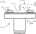
- a polishing apparatus 101 including a surface plate 103 to which a polishing cloth 102 is attached, an abrasive supply mechanism 106, a polishing head 104, and the like is used as a method for polishing one side of a wafer. be able to.
- the wafer W is held by the polishing head 104, the polishing agent is supplied onto the polishing cloth 102 from the polishing agent supply mechanism 106, and the surface plate 103 and the polishing head 104 are respectively rotated to rotate the surface of the wafer W. Polishing is performed by bringing the surface into sliding contact with the polishing cloth 102.
- the polishing apparatus 101 also has a mechanism for swinging the surface plate 103. Thereby, transfer of the minute unevenness of the polishing cloth 102 and the pattern of the groove can be suppressed.
- semiconductor wafers are often polished in multiple stages by changing the type of polishing cloth and the type of abrasive.
- a polishing apparatus having two or three surface plates called an index method is often used.
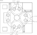
- a polishing apparatus having three surface plates is shown in FIG.
- a polishing apparatus 201 shown in FIG. 9 has two polishing heads 204 on each polishing shaft on the surface plate 203. Therefore, since two semiconductor wafers can be simultaneously polished per batch, the productivity is particularly excellent.
- the polishing apparatus generally includes a mechanism for performing brushing and dressing (hereinafter referred to as a dressing mechanism) for suppressing clogging of the polishing cloth.
- the dressing mechanism can perform dressing or the like on the polishing cloth at the time of starting up the polishing cloth or at intervals between polishing.
- a polishing agent in which colloidal silica or fumed silica is mixed with an alkaline solution is used for polishing a wafer, and a polishing agent, a dressing agent, or a solution such as pure water is used for dressing or brushing.
- a hydrophilic agent that hydrophilizes the wafer surface is added to the polishing agent, or the polishing agent is switched to a hydrophilic agent and supplied at the end of polishing. The surface is made hydrophilic.
- abrasives are circulated and reused according to the purpose of use or used for disposal.
- polishing conditions with a high cooling effect can be set by increasing the abrasive supply flow rate, but there is a demerit that the concentration of the abrasive tends to vary due to circulation.
- polishing conditions with a high cooling effect can be set by increasing the abrasive supply flow rate, but there is a demerit that the concentration of the abrasive tends to vary due to circulation.
- the abrasive is thrown away, it is difficult to increase the abrasive supply flow rate due to cost problems, but there is an advantage that the quality is easily stabilized because the concentration is constant.
- the polishing machine is provided with a waste liquid receiver for collecting used abrasives. Since the waste liquid receiver collects the slurry scattered by the rotation of the surface plate, it becomes larger than the surface plate size as disclosed in Patent Document 1. Further, Patent Document 2 discloses a polishing apparatus designed to collect only a portion where slurry is scattered. However, the polishing apparatus as in Patent Document 2 also requires a waste liquid receiver having a size larger than the swing width because the surface plate swings in the horizontal direction by the swing mechanism.
- a polishing apparatus uses a plurality of types of solutions such as abrasives.
- an abrasive and a hydrophilic agent are used during wafer polishing.
- an abrasive, a dedicated dressing agent, or pure water is used during dressing.
- polishing agent, a hydrophilic agent, a dressing agent, and a pure water will be supplied on polishing cloth.
- a switching mechanism hereinafter also referred to as a separator
- the recovery line is switched according to the solution to be recovered to recover the solution.
- FIG. 10 An example of a cross-sectional view of the separator is shown in FIG.
- the upper pipe 301 or the lower BOX 302 is moved left and right by an air cylinder or the like.
- the pipe 301 is connected to a recovery line on the surface plate side, from which the recovered solution flows into the waste liquid receiver.
- the flow of the solution is switched to the recovery line on the right side of the BOX 302 when recovering the abrasive and to the drain line on the left side of the BOX 302 when draining.
- FIG. 10 describes an example having two types of abrasive recovery lines and drainage lines, two or more types of recovery lines such as abrasive recovery lines, dressing recovery lines, and drainage lines are described. It is also possible to provide.
- the waste liquid receiver is located below the surface plate depending on the position of the surface plate. Therefore, if the angle of the waste liquid receiver is suddenly limited in a limited space, cleaning is performed when a wafer breaks. There is also a problem that maintenance becomes difficult.
- the present invention has been made in view of the above-described problems, and when recovering the abrasive, it is possible to suppress mixing with other solutions, suppress deterioration in recovery efficiency, and easy maintenance.
- An object is to provide a polishing apparatus.
- the present invention provides a surface plate to which a polishing cloth is attached, a polishing head for holding a wafer, a tank for storing an abrasive, and a tank stored in the tank.
- An abrasive supply mechanism for supplying an abrasive to the polishing cloth, a waste liquid receiver for recovering the abrasive flowing down from the surface plate, and an abrasive connected to the waste liquid receiver and recovered by the waste liquid receiver in the tank
- a polishing apparatus that performs polishing by sliding the surface of the wafer held by the polishing head against the polishing cloth while circulating the polishing agent by supplying the recovered polishing agent into the tank,
- the waste liquid receiver is To provide a polishing apparatus which is characterized in that it is fixed in a panel.
- the polishing apparatus in which the waste liquid receiver is fixed to the surface plate swings the waste liquid receiver together with the surface plate, so that it is not necessary to increase the waste liquid receiver by the amount of the swinging width as in the prior art. Accordingly, the area of the waste liquid receiver can be further reduced, and when the abrasive is recovered, mixing with other solutions can be suppressed and deterioration of the recovery efficiency of the abrasive can be suppressed. Further, since the relative position of the waste liquid receiver and the surface plate does not change due to the swing of the surface plate, the maintenance work such as cleaning of the waste liquid receiver does not become difficult depending on the position of the surface plate. Furthermore, it becomes possible to remove the waste liquid receptacle, and replacement due to breakage or the like becomes easy.
- the waste liquid receiver has a ring shape surrounding the side surface of the surface plate.
- the waste liquid receiver has a ring shape surrounding the side surface of the surface plate, the waste liquid flowing down from the entire circumference of the upper surface of the surface plate can be efficiently collected in a small area.
- the waste liquid receiver is composed of a bottom plate and a side plate, and the side plate is removable.
- the cleaning work can be performed by removing the side plate at the time of cleaning, so that the polishing apparatus is further excellent in maintainability.
- polishing apparatus of the present invention when recovering the abrasive to be reused, mixing with other solutions can be suppressed, and deterioration in recovery efficiency can be suppressed. In addition, maintenance work such as cleaning of the waste liquid receiver does not become difficult depending on the position of the surface plate.
- the waste liquid receiver is installed below the surface plate, so that the size of the waste liquid receiver needs to be extremely increased in accordance with the swinging width of the surface plate.
- the area of the waste liquid receiver is large, there is a problem that the amount of the solution mixed increases and the recovery efficiency deteriorates.
- the waste liquid receiver is positioned on the lower side of the surface plate depending on the position of the surface plate, there is a problem that maintenance such as cleaning when the wafer is cracked becomes difficult.
- the present inventors have intensively studied to solve such problems. As a result, if the waste liquid receiver is fixed to the surface plate, it is not necessary to increase the size of the waste liquid receiver more than necessary, and when collecting the abrasive, the mixing and dilution with dressing and pure water is suppressed and polishing is performed. It was found that the quality of the agent can be stabilized and the amount used can be reduced, and that good maintainability of the apparatus can be obtained, and the present invention has been completed.
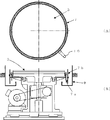
- a polishing apparatus 1 of the present invention includes a surface plate 3 to which a polishing cloth 2 is attached, a polishing head 4 for holding a wafer W, a tank 5 for storing an abrasive,
- the abrasive supply mechanism 6 for supplying the abrasive stored in the tank 5 to the polishing cloth 2, the waste liquid receiver 7 for collecting the abrasive flowing down from the surface plate 3, and the waste liquid receiver 7 are connected to the waste liquid receiver.
- a circulation mechanism 8 for supplying the abrasive recovered by the receiver 7 into the tank 5 is provided.
- polishing apparatus of this invention is not limited to this.
- one or three or more polishing heads may be provided on one surface plate.
- the number of surface plates is not particularly limited, and a plurality of surface plates may be provided.
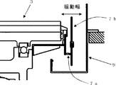
- the waste liquid receiver 7 is fixed to the surface plate 3. Accordingly, the area of the waste liquid receiver can be reduced regardless of the presence or absence of the swing of the surface plate and the size of the surface plate, so that mixing of the polishing solution can be suppressed and recovery efficiency can be improved. Further, since the relative position with respect to the surface plate does not change due to the swinging of the surface plate, maintenance work such as cleaning of the waste liquid receiver does not become difficult depending on the position of the surface plate. Therefore, the time required for the maintenance work can be shortened, and the apparatus stop time can be shortened.
- a stay can be attached to the lower part of the surface plate 3 to fix the waste liquid receiver 7 to the surface plate 3.
- the shape of the waste liquid receiver 7 can be a ring shape surrounding the side surface of the surface plate 3. If it is such, the waste liquid which flows down from the perimeter of the upper surface of the surface plate 3 can be efficiently recovered in a small area.
- the waste liquid receiver 7 may be composed of a bottom plate 7a and a side plate 7b, or the side plate 7b may be removable. If it is such, since it becomes possible to remove a side plate at the time of cleaning and to perform the cleaning work, the workability at the time of maintenance is further improved.
- the waste liquid receiver 7 is preferably a synthetic resin such as vinyl chloride.
- a waste liquid tray 9 is disposed outside the waste liquid receiver 7.
- the waste liquid tray 9 can prevent water from entering the machine room of the surface plate 3 when the surface plate 3 is cleaned by a hand shower or the like with the side plate 7b of the waste liquid receiver 7 removed during maintenance.
- the waste liquid tray 9 is preferably a synthetic resin such as vinyl chloride.
- the polishing agent 2 is supplied from the tank 5 to the polishing cloth 2 by the pump 12 or the like attached to the polishing agent supply mechanism 6, and the used polishing agent flowing down from the surface plate 3 is used as the waste liquid receiver 7. Collect with.
- the used abrasive recovered by the waste liquid receiver 7 is supplied into the tank 5 by a circulation mechanism 8 including a waste liquid recovery line 10, a separator 11, and the like.
- the separator 11 can be switched between the recovery line and the drain line.
- the separator 11 for example, the same material as a conventional separator as shown in FIG. 10 can be used.
- polishing is performed by sliding the surface of the wafer W held by the polishing head 4 in sliding contact with the polishing pad 2 while circulating the polishing agent in this way.
- polishing agent is difficult to mix with other solutions even if the polishing agent is circulated and reused. Accordingly, it is difficult to dilute the polishing agent, and the fluctuation of the polishing rate can be suppressed. Moreover, since the amount of the abrasive that cannot be reused due to mixing with other solutions can be reduced, the cost of the abrasive can be reduced.
- Example 2 A silicon wafer having a diameter of 300 mm was polished while the abrasive was circulated and reused using the polishing apparatus of the present invention.
- the polishing apparatus used was an index type polishing apparatus having three surface plates and two polishing heads per surface plate.
- the diameter of the surface plate was 800 mm.
- a stay is attached to the lower part of the surface plate 3, and a waste liquid receptacle 7 made of vinyl chloride is fixed to the surface plate 3. Since the waste liquid receiver swings together with the surface plate, the area of the waste liquid receiver could be reduced to a size that does not overflow at the maximum polishing flow rate. As a result, the area (area occupied by the plane) of the waste liquid receiver was 68.3 mm 2 , which was reduced to about 1/5 of the comparative example described later. In the example, in order to suppress the mixing of the polishing liquid and improve the recovery efficiency, an inclination is provided inside the waste liquid receiver.
- condition 1 In condition 1, the separator line was switched at a timing such that the amount of abrasive in the tank did not decrease. Under these conditions, pure water is mixed with the abrasive, the abrasive is diluted, and the polishing rate tends to decrease. When the variation of the polishing rate was examined, as shown in FIG. 4, in the example, the decrease in the polishing rate was suppressed to 7%. In FIG. 4, the polishing rate of each batch is a relative value to the polishing rate of the first batch.
- Condition 2 In condition 2, the separator was switched at a timing when pure water was not mixed with the abrasive. Under this condition, the amount of abrasive discharged tends to increase. The discharged amount was determined from the remaining amount of the slurry tank after 10 batches of continuous polishing. As a result, as shown in FIG. 5, the amount of abrasive discharged in the example was 38%.
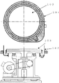
- the area of the waste liquid receiver (plane occupation area) was 307.3 mm 2 . Due to the swinging width, the area could not be further reduced.
- an inclination is provided inside the waste liquid receiver.
- the polishing rate was reduced by 24% in the comparative example. As described above, the polishing rate was greatly reduced as compared with the Example.
- the present invention is not limited to the above embodiment.
- the above-described embodiment is an exemplification, and the present invention has any configuration that has substantially the same configuration as the technical idea described in the claims of the present invention and that exhibits the same effects. Are included in the technical scope.
Landscapes
- Engineering & Computer Science (AREA)
- Mechanical Engineering (AREA)
- Finish Polishing, Edge Sharpening, And Grinding By Specific Grinding Devices (AREA)
- Grinding-Machine Dressing And Accessory Apparatuses (AREA)
- Mechanical Treatment Of Semiconductor (AREA)
Abstract
Description
本発明の研磨装置を用いて研磨剤を循環させ再使用しながら、直径300mmのシリコンウェーハの研磨を行った。また、研磨装置は、3つの定盤を有し、1定盤当たり2つの研磨ヘッドを持つインデックス方式の研磨装置を用いた。定盤の直径は800mmであった。
条件1では、タンク内の研磨剤量が低下しないようなタイミングで、セパレーターのライン切り換えを行った。この条件では、研磨剤に純水が混合し、研磨剤が希釈され、研磨レートが低下しやすい。研磨レートの変動を調べたところ、図4に示すように、実施例では、研磨レートの低下は7%に抑制された。なお、図4では、各バッチの研磨レートは、1バッチ目の研磨レートに対する相対値としている。
また、条件2では、研磨剤に純水が混合しないタイミングでセパレーターの切り換えを行った。この条件では、研磨剤の排出量が増加しやすい。10バッチの連続研磨後のスラリータンクの残量から、排出量を求めた。その結果、図5に示すように、実施例の研磨剤の排出量は38%となった。
廃液受けを定盤に固定していない従来の研磨装置を用いたこと以外、実施例と同様な条件で実施例と同様に研磨レート及び研磨剤の排出量を評価した。比較例で用いた研磨装置は、図6、7に示すように、廃液受け107が、定盤103に固定されていないため、定盤103の揺動により廃液受け107と定盤103の相対位置が変化する。よって、定盤位置に関わらず研磨剤を回収するためには、廃液受けの面積を大きくすることが必須である。比較例における定盤サイズと揺動幅の場合を考慮した結果、廃液受けの面積(平面占有面積)は307.3mm2となった。揺動幅の問題で、これ以上面積を小さくすることはできなかった。なお、実施例と同様に、研磨液の混合を抑制し、回収効率を改善するため、廃液受け内部に傾斜を設けている。
Claims (3)
- 研磨布が貼り付けられた定盤と、ウェーハを保持するための研磨ヘッドと、研磨剤を貯蔵するためのタンクと、該タンク内に貯蔵された研磨剤を前記研磨布に供給する研磨剤供給機構と、前記定盤上から流下する研磨剤を回収する廃液受けと、該廃液受けに接続され、前記廃液受けで回収した研磨剤を前記タンク内に供給する循環機構を具備し、前記研磨剤供給機構で前記タンク内から前記研磨剤を前記研磨布に供給し、前記定盤上から流下する使用済みの研磨剤を前記廃液受けで回収し、該回収した研磨剤を前記タンク内に供給することで前記研磨剤を循環させながら、前記研磨ヘッドで保持した前記ウェーハの表面を前記研磨布に摺接させて研磨を行う研磨装置であって、
前記廃液受けが、前記定盤に固定されたものであることを特徴とする研磨装置。 - 前記廃液受けが、前記定盤の側面を囲むリング状のものであることを特徴とする請求項1に記載の研磨装置。
- 前記廃液受けが、底板及び側板から成るものであり、前記側板が取り外し可能なものであることを特徴とする請求項1又は請求項2に記載の研磨装置。
Priority Applications (5)
| Application Number | Priority Date | Filing Date | Title |
|---|---|---|---|
| DE112016003354.0T DE112016003354T5 (de) | 2015-08-21 | 2016-08-03 | Poliervorrichtung |
| KR1020187004634A KR102550998B1 (ko) | 2015-08-21 | 2016-08-03 | 연마 장치 |
| US15/750,329 US10850365B2 (en) | 2015-08-21 | 2016-08-03 | Polishing apparatus with a waste liquid receiver |
| CN201680047958.3A CN107921605A (zh) | 2015-08-21 | 2016-08-03 | 研磨装置 |
| SG11201800897PA SG11201800897PA (en) | 2015-08-21 | 2016-08-03 | Polishing apparatus |
Applications Claiming Priority (2)
| Application Number | Priority Date | Filing Date | Title |
|---|---|---|---|
| JP2015-163908 | 2015-08-21 | ||
| JP2015163908A JP6389449B2 (ja) | 2015-08-21 | 2015-08-21 | 研磨装置 |
Publications (1)
| Publication Number | Publication Date |
|---|---|
| WO2017033409A1 true WO2017033409A1 (ja) | 2017-03-02 |
Family
ID=58099645
Family Applications (1)
| Application Number | Title | Priority Date | Filing Date |
|---|---|---|---|
| PCT/JP2016/003575 Ceased WO2017033409A1 (ja) | 2015-08-21 | 2016-08-03 | 研磨装置 |
Country Status (8)
| Country | Link |
|---|---|
| US (1) | US10850365B2 (ja) |
| JP (1) | JP6389449B2 (ja) |
| KR (1) | KR102550998B1 (ja) |
| CN (1) | CN107921605A (ja) |
| DE (1) | DE112016003354T5 (ja) |
| SG (1) | SG11201800897PA (ja) |
| TW (1) | TWI715606B (ja) |
| WO (1) | WO2017033409A1 (ja) |
Cited By (1)
| Publication number | Priority date | Publication date | Assignee | Title |
|---|---|---|---|---|
| JP2020011329A (ja) * | 2018-07-17 | 2020-01-23 | スピードファム株式会社 | 処理液切換装置 |
Families Citing this family (5)
| Publication number | Priority date | Publication date | Assignee | Title |
|---|---|---|---|---|
| US11244834B2 (en) * | 2018-07-31 | 2022-02-08 | Taiwan Semiconductor Manufacturing Co., Ltd. | Slurry recycling for chemical mechanical polishing system |
| KR102308092B1 (ko) * | 2020-03-06 | 2021-10-05 | 넥센타이어 주식회사 | 타이어의 마모 측정 장치 |
| JP7746217B2 (ja) * | 2022-05-13 | 2025-09-30 | 株式会社荏原製作所 | 処理システムおよびパッド搬送装置 |
| EP4572913A1 (en) * | 2022-08-18 | 2025-06-25 | Applied Materials, Inc. | Polishing fluid recovery and reuse system for semiconductor substrate processing |
| CN120055988B (zh) * | 2025-04-25 | 2025-08-19 | 通威微电子有限公司 | 抛光清洗干燥一体机 |
Citations (4)
| Publication number | Priority date | Publication date | Assignee | Title |
|---|---|---|---|---|
| GB1261131A (en) * | 1969-06-06 | 1972-01-19 | Burmah Oil Trading Ltd | Improvements in or relating to lapping machines |
| JPH0732263A (ja) * | 1993-07-20 | 1995-02-03 | Speedfam Co Ltd | 研磨液飛散防止機構付き平面研磨装置 |
| JPH11254298A (ja) * | 1998-03-06 | 1999-09-21 | Speedfam Co Ltd | スラリー循環供給式平面研磨装置 |
| JP2009248269A (ja) * | 2008-04-09 | 2009-10-29 | Nikon Corp | 研磨装置 |
Family Cites Families (22)
| Publication number | Priority date | Publication date | Assignee | Title |
|---|---|---|---|---|
| US3500591A (en) * | 1966-11-21 | 1970-03-17 | Owens Illinois Inc | Glass grinding method and apparatus |
| US4869779A (en) * | 1987-07-27 | 1989-09-26 | Acheson Robert E | Hydroplane polishing device and method |
| JP2606156B2 (ja) * | 1994-10-14 | 1997-04-30 | 栗田工業株式会社 | 研磨剤粒子の回収方法 |
| US5658185A (en) * | 1995-10-25 | 1997-08-19 | International Business Machines Corporation | Chemical-mechanical polishing apparatus with slurry removal system and method |
| US5664990A (en) * | 1996-07-29 | 1997-09-09 | Integrated Process Equipment Corp. | Slurry recycling in CMP apparatus |
| US5791970A (en) * | 1997-04-07 | 1998-08-11 | Yueh; William | Slurry recycling system for chemical-mechanical polishing apparatus |
| JPH10324865A (ja) | 1997-05-23 | 1998-12-08 | Yamaha Corp | 研磨剤生成方法及び研磨方法 |
| WO1999033612A1 (en) * | 1997-12-26 | 1999-07-08 | Ebara Corporation | Polishing device |
| JPH11277434A (ja) | 1998-03-30 | 1999-10-12 | Speedfam Co Ltd | Cmp装置のスラリリサイクルシステム及びその方法 |
| JPH11320406A (ja) * | 1998-05-06 | 1999-11-24 | Speedfam-Ipec Co Ltd | 研磨装置における排液・排気の処理方法及び装置 |
| TW504776B (en) * | 1999-09-09 | 2002-10-01 | Mimasu Semiconductor Ind Co | Wafer rotary holding apparatus and wafer surface treatment apparatus with waste liquid recovery mechanism |
| JP4657412B2 (ja) * | 1999-12-10 | 2011-03-23 | エルエスアイ コーポレーション | 半導体ウェハを研磨する装置及び方法 |
| US6705930B2 (en) * | 2000-01-28 | 2004-03-16 | Lam Research Corporation | System and method for polishing and planarizing semiconductor wafers using reduced surface area polishing pads and variable partial pad-wafer overlapping techniques |
| US6558238B1 (en) * | 2000-09-19 | 2003-05-06 | Agere Systems Inc. | Apparatus and method for reclamation of used polishing slurry |
| JP3852758B2 (ja) * | 2002-03-01 | 2006-12-06 | インターナショナル・ビジネス・マシーンズ・コーポレーション | スラリー回収装置及びその方法 |
| US7584760B2 (en) * | 2002-09-13 | 2009-09-08 | Dainippon Screen Mfg. Co., Ltd. | Substrate processing apparatus |
| JP3889744B2 (ja) * | 2003-12-05 | 2007-03-07 | 株式会社東芝 | 研磨ヘッドおよび研磨装置 |
| JP2007088398A (ja) * | 2004-12-14 | 2007-04-05 | Realize Advanced Technology Ltd | 洗浄装置、この洗浄装置を用いた洗浄システム、及び被洗浄基板の洗浄方法 |
| EP2372749B1 (de) * | 2010-03-31 | 2021-09-29 | Levitronix GmbH | Behandlungsvorrichtung zur Behandlung einer Oberfläche eines Körpers |
| US9339914B2 (en) * | 2012-09-10 | 2016-05-17 | Applied Materials, Inc. | Substrate polishing and fluid recycling system |
| CN204094614U (zh) | 2014-09-24 | 2015-01-14 | 江苏中科晶元信息材料有限公司 | 一种晶片研磨机中环形防护筒的安装结构 |
| JP6792363B2 (ja) * | 2016-07-22 | 2020-11-25 | 株式会社ディスコ | 研削装置 |
-
2015
- 2015-08-21 JP JP2015163908A patent/JP6389449B2/ja active Active
-
2016
- 2016-08-03 WO PCT/JP2016/003575 patent/WO2017033409A1/ja not_active Ceased
- 2016-08-03 KR KR1020187004634A patent/KR102550998B1/ko active Active
- 2016-08-03 SG SG11201800897PA patent/SG11201800897PA/en unknown
- 2016-08-03 US US15/750,329 patent/US10850365B2/en active Active
- 2016-08-03 DE DE112016003354.0T patent/DE112016003354T5/de active Pending
- 2016-08-03 CN CN201680047958.3A patent/CN107921605A/zh active Pending
- 2016-08-09 TW TW105125238A patent/TWI715606B/zh active
Patent Citations (4)
| Publication number | Priority date | Publication date | Assignee | Title |
|---|---|---|---|---|
| GB1261131A (en) * | 1969-06-06 | 1972-01-19 | Burmah Oil Trading Ltd | Improvements in or relating to lapping machines |
| JPH0732263A (ja) * | 1993-07-20 | 1995-02-03 | Speedfam Co Ltd | 研磨液飛散防止機構付き平面研磨装置 |
| JPH11254298A (ja) * | 1998-03-06 | 1999-09-21 | Speedfam Co Ltd | スラリー循環供給式平面研磨装置 |
| JP2009248269A (ja) * | 2008-04-09 | 2009-10-29 | Nikon Corp | 研磨装置 |
Cited By (2)
| Publication number | Priority date | Publication date | Assignee | Title |
|---|---|---|---|---|
| JP2020011329A (ja) * | 2018-07-17 | 2020-01-23 | スピードファム株式会社 | 処理液切換装置 |
| JP7019184B2 (ja) | 2018-07-17 | 2022-02-15 | スピードファム株式会社 | 処理液切換装置 |
Also Published As
| Publication number | Publication date |
|---|---|
| CN107921605A (zh) | 2018-04-17 |
| JP6389449B2 (ja) | 2018-09-12 |
| TWI715606B (zh) | 2021-01-11 |
| KR20180042250A (ko) | 2018-04-25 |
| DE112016003354T5 (de) | 2018-04-05 |
| TW201713461A (zh) | 2017-04-16 |
| JP2017039193A (ja) | 2017-02-23 |
| US10850365B2 (en) | 2020-12-01 |
| US20180222008A1 (en) | 2018-08-09 |
| KR102550998B1 (ko) | 2023-07-04 |
| SG11201800897PA (en) | 2018-03-28 |
Similar Documents
| Publication | Publication Date | Title |
|---|---|---|
| JP6389449B2 (ja) | 研磨装置 | |
| JP3594357B2 (ja) | ポリッシング方法及び装置 | |
| KR20190052138A (ko) | 웨이퍼의 엣지 연마 장치 및 방법 | |
| JP6747599B2 (ja) | シリコンウェーハの両面研磨方法 | |
| TW201535500A (zh) | 晶圓拋光製程、晶圓拋光工具與積體電路裝置製程 | |
| JP2019029562A (ja) | 基板処理装置 | |
| CN101121247A (zh) | 研磨头的清洗装置 | |
| JP6468037B2 (ja) | 研磨装置 | |
| JP6007553B2 (ja) | ウエーハの研磨方法 | |
| CN209831364U (zh) | 组合式晶片研磨盘 | |
| WO2015049829A1 (ja) | 研磨布の洗浄方法及びウェーハの研磨方法 | |
| CN103878680A (zh) | 降低晶圆被刮伤的方法、化学机械研磨机台及清洗器 | |
| CN110625528B (zh) | 一种抛光垫的修整装置及修整方法 | |
| JP6197752B2 (ja) | ウェーハの研磨方法 | |
| CN101279435B (zh) | 一种改进型抛光垫调节器工艺 | |
| KR101366153B1 (ko) | 웨이퍼 연마 장치의 드레서 | |
| KR20100052028A (ko) | 양면 연마기의 패드 드레싱 방법 | |
| CN110293481A (zh) | 一种研磨设备和研磨设备的清洁方法 | |
| CN209207257U (zh) | 一种磨床用磨削液循环利用装置 | |
| CN117359472B (zh) | 边缘抛光设备及边缘抛光方法 | |
| JP5310259B2 (ja) | 研磨装置およびワークの研磨方法 | |
| CN217453254U (zh) | 一种刹车盘打磨装置 | |
| CN210524837U (zh) | 一种抛光垫修整器 | |
| JPH10118915A (ja) | 化学的機械研磨方法及び化学的機械研磨装置 | |
| KR200201955Y1 (ko) | 대구경용 화학 기계적 연마 장치 및 그를 이용한 화학기계적 연마 방법 |
Legal Events
| Date | Code | Title | Description |
|---|---|---|---|
| 121 | Ep: the epo has been informed by wipo that ep was designated in this application |
Ref document number: 16838761 Country of ref document: EP Kind code of ref document: A1 |
|
| WWE | Wipo information: entry into national phase |
Ref document number: 11201800897P Country of ref document: SG |
|
| WWE | Wipo information: entry into national phase |
Ref document number: 15750329 Country of ref document: US |
|
| ENP | Entry into the national phase |
Ref document number: 20187004634 Country of ref document: KR Kind code of ref document: A |
|
| WWE | Wipo information: entry into national phase |
Ref document number: 112016003354 Country of ref document: DE |
|
| 122 | Ep: pct application non-entry in european phase |
Ref document number: 16838761 Country of ref document: EP Kind code of ref document: A1 |