WO2016208124A1 - ゴムクローラの製造方法 - Google Patents
ゴムクローラの製造方法 Download PDFInfo
- Publication number
- WO2016208124A1 WO2016208124A1 PCT/JP2016/002616 JP2016002616W WO2016208124A1 WO 2016208124 A1 WO2016208124 A1 WO 2016208124A1 JP 2016002616 W JP2016002616 W JP 2016002616W WO 2016208124 A1 WO2016208124 A1 WO 2016208124A1
- Authority
- WO
- WIPO (PCT)
- Prior art keywords
- rubber
- crawler
- vulcanized
- semi
- mold
- Prior art date
- Legal status (The legal status is an assumption and is not a legal conclusion. Google has not performed a legal analysis and makes no representation as to the accuracy of the status listed.)
- Ceased
Links
Images




Classifications
-
- B—PERFORMING OPERATIONS; TRANSPORTING
- B29—WORKING OF PLASTICS; WORKING OF SUBSTANCES IN A PLASTIC STATE IN GENERAL
- B29D—PRODUCING PARTICULAR ARTICLES FROM PLASTICS OR FROM SUBSTANCES IN A PLASTIC STATE
- B29D29/00—Producing belts or bands
-
- B—PERFORMING OPERATIONS; TRANSPORTING
- B29—WORKING OF PLASTICS; WORKING OF SUBSTANCES IN A PLASTIC STATE IN GENERAL
- B29C—SHAPING OR JOINING OF PLASTICS; SHAPING OF MATERIAL IN A PLASTIC STATE, NOT OTHERWISE PROVIDED FOR; AFTER-TREATMENT OF THE SHAPED PRODUCTS, e.g. REPAIRING
- B29C35/00—Heating, cooling or curing, e.g. crosslinking or vulcanising; Apparatus therefor
- B29C35/02—Heating or curing, e.g. crosslinking or vulcanizing during moulding, e.g. in a mould
-
- B—PERFORMING OPERATIONS; TRANSPORTING
- B29—WORKING OF PLASTICS; WORKING OF SUBSTANCES IN A PLASTIC STATE IN GENERAL
- B29C—SHAPING OR JOINING OF PLASTICS; SHAPING OF MATERIAL IN A PLASTIC STATE, NOT OTHERWISE PROVIDED FOR; AFTER-TREATMENT OF THE SHAPED PRODUCTS, e.g. REPAIRING
- B29C35/00—Heating, cooling or curing, e.g. crosslinking or vulcanising; Apparatus therefor
- B29C35/02—Heating or curing, e.g. crosslinking or vulcanizing during moulding, e.g. in a mould
- B29C35/0227—Heating or curing, e.g. crosslinking or vulcanizing during moulding, e.g. in a mould using pressure vessels, e.g. autoclaves, vulcanising pans
-
- B—PERFORMING OPERATIONS; TRANSPORTING
- B62—LAND VEHICLES FOR TRAVELLING OTHERWISE THAN ON RAILS
- B62D—MOTOR VEHICLES; TRAILERS
- B62D55/00—Endless track vehicles
- B62D55/08—Endless track units; Parts thereof
- B62D55/18—Tracks
- B62D55/24—Tracks of continuously flexible type, e.g. rubber belts
- B62D55/253—Tracks of continuously flexible type, e.g. rubber belts having elements interconnected by one or more cables or like elements
-
- B—PERFORMING OPERATIONS; TRANSPORTING
- B62—LAND VEHICLES FOR TRAVELLING OTHERWISE THAN ON RAILS
- B62D—MOTOR VEHICLES; TRAILERS
- B62D55/00—Endless track vehicles
- B62D55/08—Endless track units; Parts thereof
- B62D55/18—Tracks
- B62D55/24—Tracks of continuously flexible type, e.g. rubber belts
Definitions
- the present invention relates to a method for producing a rubber crawler.
- unvulcanized rubber having a predetermined length is attached to the inner peripheral side and the outer peripheral side of a tensile body, and these are sandwiched between an upper mold and a lower mold and added.
- a method of obtaining an annular rubber crawler by integrally vulcanizing and bonding the longitudinal ends of uncured rubber crawlers after obtaining a belt-shaped rubber crawler by performing sulfur molding for example, patents) Reference 1).
- the rubber protrusion and the main body are unvulcanized by closing the mold on which the unvulcanized rubber (raw rubber) including the portions to be rubber protrusions (for example, drive protrusion and lug) is disposed.
- the unvulcanized rubber has fluidity.
- the rubber having fluidity flows from the high pressure portion toward the low pressure portion.
- the low pressure portion is mainly a thick portion of the rubber crawler, that is, a recess in which a rubber protrusion is formed in the mold and the unvulcanized rubber is disposed. Therefore, when trying to obtain a rubber crawler integrally by closing the mold of the unvulcanized rubber, the rubber having fluidity flows toward the recess in the mold where the rubber protrusion is formed.
- An object of the present invention is to provide a method for producing a rubber crawler that can suppress deformation of a tensile body that may occur during production.
- the rubber crawler manufacturing method includes a rubber protrusion forming step of obtaining a rubber protrusion having a semi-vulcanized surface by vulcanizing unvulcanized rubber so that a part of the surface remains in a semi-vulcanized state.
- the rubber protrusion is arranged on the main body with the semi-vulcanized surface of the rubber protrusion aligned with the semi-vulcanized surface of the main body, and then the rubber And a rubber crawler forming step of integrating the protrusion and the main body by vulcanization.
- the rubber crawler forming step vulcanizes the rubber protrusion and the main body in a space that can be controlled at high temperature and high pressure. In this case, a mold for integrating the rubber protrusion and the main body becomes unnecessary.
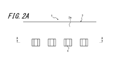
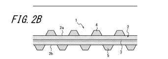
- FIG. 1 It is a side view which shows an example of the rubber crawler which can be manufactured with the manufacturing method of the rubber crawler which concerns on one Embodiment of this invention. It is the top view which looked at the rubber crawler of FIG. 1 from the inner peripheral side. 2B is a cross-sectional view taken along the line AA in FIGS. 2A and 2C in the rubber crawler in FIG. 1. FIG. It is the top view which looked at the rubber crawler of FIG. 1 from the outer peripheral side. It is sectional drawing which shows an example of the rubber protrusion formation type
- FIG. 2 is an example of a second step of a rubber crawler forming step in a method of manufacturing a rubber crawler according to an embodiment of the present invention that can be used for manufacturing the rubber crawler of FIG.
- It is another example of the 2nd process of the rubber crawler formation process in the manufacturing method of the rubber crawler which concerns on one Embodiment of this invention which can be used for manufacture of the rubber crawler of FIG.
- reference numeral 1 denotes a rubber crawler that can be manufactured by the rubber crawler manufacturing method of the present invention.
- the rubber crawler 1 has an endless belt-like crawler main body (main body) 2 made of vulcanized rubber.
- a tensile body (for example, a steel cord) 3 is embedded in the crawler main body 2.
- the tensile body 3 extends in the circumferential direction of the crawler main body 2 and is arranged in a plurality with a gap in the width direction of the crawler main body (the front and back direction in FIG. 2B).
- a reinforcing layer or the like can be embedded on the inner and outer peripheral sides of the tensile body 3 in the crawler body.
- Numeral 4 is a drive protrusion (rubber protrusion) provided on the inner peripheral surface 2a of the crawler body 2.
- the drive protrusion 4 is made of vulcanized rubber.
- the drive protrusion 4 meshes with a sprocket (not shown) to cause the rubber crawler 1 to rotate.
- a plurality of drive protrusions 4 are arranged at intervals in the circumferential direction of the crawler main body 2 (left and right direction in the figure). The shape and arrangement of the drive protrusion 4 can be changed as appropriate.
- reference numeral 5 denotes a lug (rubber protrusion) provided on the outer peripheral surface 2 b of the crawler body 2.
- the lug 5 is made of vulcanized rubber.
- a plurality of lugs 5 are arranged at intervals in the circumferential direction of the crawler body 2.
- a plurality of lugs 5 are alternately arranged in the circumferential direction of the crawler body 2. The shape and arrangement of the lugs 5 can be changed as appropriate.
- the rubber crawler 1 is manufactured by vulcanizing an unvulcanized rubber RR so that a part of the surface remains in a semi-vulcanized state, and a rubber protrusion having a semi-vulcanized surface (in this embodiment) , A drive protrusion 4 and a lug 5) are provided, and a rubber protrusion forming step is provided.
- reference numeral 10 denotes an example of a rubber protrusion forming mold used in the rubber protrusion forming step in the method of manufacturing the rubber crawler 1 according to the embodiment of the present invention.
- the rubber projection forming mold 10 has an upper mold 11 that forms the inner shape of the drive protrusion 4 and a lower mold 12 that forms the outer shape of the drive protrusion 4.
- the mating surface 11 a of the upper mold 11 and the lower mold 12 are formed.
- a cavity C1 for forming the drive protrusion 4 is formed.
- An unvulcanized rubber RR is disposed in the cavity C1.
- the upper mold 11 is made of metal such as iron or aluminum alloy, and a heating means H is provided on the upper mold 11.
- the heating means H heats the inside of the cavity C1 through the upper mold 11 from the upper side.
- the lower mold 12 is made of a metal such as iron or an aluminum alloy, and a heating means H is provided on the lower side thereof.
- the heating means H heats the inside of the cavity C1 from the lower side through the lower mold 12. Thereby, the inside of the cavity C1 can be heated by the two heating means H.
- Examples of the heating unit H include a heater using vapor pressure or electricity.
- the upper mold 11 further includes a heat insulating material 13 as a heat insulating means.
- the heat insulating material 13 blocks the heat from the heating means H and suppresses the heating from the upper mold 11 to the unvulcanized rubber RR in the cavity C1.
- the heat insulating material 13 is embedded in the upper mold 11.
- the surface 13 a of the heat insulating material 13 is embedded so as to be the same surface as the mating surface 11 a of the upper mold 11.
- the unvulcanized rubber RR in contact with the surface 13a of the heat insulating material 13 is suppressed from heat conduction from the upper mold 11, so that the portion that is in contact with the surface 13a of the heat insulating material 13 is semi-vulcanized. It becomes a state.
- the heat insulating material include a fluororesin heat insulating material such as polytetrafluoroethylene (PTFE) and a glass cloth heat insulating material.
- the drive protrusion 4 is formed by disposing the unvulcanized rubber RR in the cavity C1 in the rubber protrusion forming mold 10 and closing the mold, and then heating the upper mold 11 and the lower mold 12 using the heating means H. Can do.
- the cavity is formed so that a part of the surface of the driving protrusion 4 (in this example, the joint surface with the inner peripheral surface 2a of the crawler body 2) remains in a semi-vulcanized state.
- Unvulcanized rubber RR in C1 can be vulcanized.
- the drive projection 4 having the semi-vulcanized surface 4a as shown in FIG. 5 can be obtained.
- the semi-vulcanized state refers to a state where there is room for vulcanization without being completely vulcanized, in other words, a state where there is room for vulcanization adhesion.
- the semi-vulcanized state means a state before the raw rubber becomes a vulcanized rubber and includes an unvulcanized state.
- the lug 5 is also closed with the unvulcanized rubber RR disposed in the cavity C1 in the rubber projection forming mold using the same rubber projection forming mold as the rubber projection forming mold 10, and then the heating means H is changed. It can be formed by heating the upper mold 11 and the lower mold 12.
- the rubber protrusion forming mold similar to the rubber protrusion forming mold 10 is used, the unvulcanized portion in the cavity C1 is left so that a part of the surface of the lug 5 remains in a semi-vulcanized state, like the driving protrusion 4.
- the rubber RR can be vulcanized.
- the lug 5 having the semi-vulcanized surface 5a as shown in FIG. 5 can be obtained.
- the upper mold 11 and the lower mold 12 are heated using the heating means H.
- rubber protrusions such as the drive protrusion 4 and the lug 5 are formed.
- Vulcanization of the unvulcanized rubber RR is performed by adjusting the temperature of the heating means H, for example, between 160 ° C. and 180 ° C.
- the semi-vulcanized state is removed from the upper mold 11 by the heat insulating material 13. This is achieved by setting the temperature transmitted into the cavity C1 to be, for example, 100 ° C. or less.
- the manufacturing method of the rubber crawler 1 according to the present embodiment is such that at least the planned location where the rubber protrusions (in the present embodiment, the drive protrusions 4 and the lugs 5) are arranged remains in a semi-vulcanized state.
- reference numeral 20 denotes an example of a crawler main body forming mold used in the crawler main body forming step (main body forming step) in the method of manufacturing the rubber crawler 1 according to the present embodiment.
- parts that are substantially the same as the above-described configuration are denoted by the same reference numerals and description thereof is omitted.
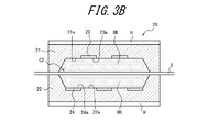
- the crawler body forming mold 20 includes an upper mold 21 that forms the inner peripheral side shape of the crawler main body 2 and a lower mold 22 that forms the outer peripheral side shape of the crawler main body 2, and as illustrated, the upper mold 21 and the lower mold
- a cavity C ⁇ b> 2 for forming the crawler body 2 is formed.
- a tensile body 3 an unvulcanized rubber RR having a predetermined length disposed on the inner peripheral side (upper side of the drawing) of the tensile body 3, and an outer peripheral side of the tensile body 3
- An unvulcanized rubber RR having a predetermined length is disposed on the lower side of the drawing.
- the upper mold 21 is made of a metal such as iron or an aluminum alloy, and a heating means H is provided on the upper mold 21.
- the heating means H heats the inside of the cavity C2 through the upper mold 21 from the upper side.
- the lower mold 22 is made of a metal such as iron or an aluminum alloy, and a heating means H is provided on the lower side thereof.
- the heating means H heats the inside of the cavity C2 through the lower mold 22 from the lower side. Thereby, the inside of the cavity C2 can be heated by the two heating means H.
- the upper mold 21 further includes a heat insulating material 23 as a heat insulating means.
- the heat insulating material 23 blocks the heat from the heating means H and suppresses the heating from the upper mold 21 to the unvulcanized rubber RR in the cavity C2.
- the heat insulating material 23 is disposed at least at a planned location where the drive protrusion 4 is disposed.
- the heat insulating material 23 is embedded in the upper mold 21.
- the surface 23 a of the heat insulating material 23 is the same surface as the crawler body inner peripheral side forming surface 21 a that forms the inner peripheral surface 2 a of the crawler main body 2 in the upper mold 21.
- the heat insulating material 23 is embedded.
- the unvulcanized rubber RR When heated by the heating means H, the unvulcanized rubber RR suppresses heat conduction from the upper mold 21 at a position in contact with the surface 23a of the heat insulating material 23. Therefore, in the portion in contact with the surface 23a of the heat insulating material 23, the crawler The inner peripheral surface 2a of the main body 2 is locally in a semi-vulcanized state.
- a heat insulating material like the heat insulating material 13, a fluororesin heat insulating material and a glass cloth heat insulating material are mentioned, for example.
- the lower mold 22 further includes a heat insulating material 24 as a heat insulating means.
- the heat insulating material 24 blocks heat from the heating means H and suppresses heating from the lower mold 22 to the unvulcanized rubber RR in the cavity C2.
- the heat insulating material 24 is arrange
- the heat insulating material 24 is embedded in the lower mold 22.
- the heat insulating material 24 has a surface 24 a that is the same as the crawler body outer peripheral side forming surface 22 a that forms the outer peripheral surface 2 b of the crawler main body 2 in the lower mold 22. 24 is buried.
- the unvulcanized rubber RR When heated by the heating means H, the unvulcanized rubber RR suppresses heat conduction from the lower mold 22 at the position where it contacts the surface 24a of the heat insulating material 24.
- the outer peripheral surface 2b of the main body 2 is locally in a semi-vulcanized state.
- the heat insulating material 24 for example, a fluororesin heat insulating material and a glass cloth heat insulating material can be used as in the heat insulating materials 13 and 23.
- the belt-like crawler body 2 is disposed in the cavity C2 in the crawler body forming mold 20 by disposing the unvulcanized rubber RR embedded with the tensile body 3 and then closing the mold, and then using the heating means H and the upper mold 21 and The lower mold 22 can be formed by heating.
- the unvulcanized rubber RR in the cavity C2 is vulcanized so that the planned location where the drive protrusion 4 and the lug 5 are arranged remains in a semi-vulcanized state. Can do.
- the crawler main body forming mold 20 by using the crawler main body forming mold 20, as shown in FIG.
- the unvulcanized rubber RR in which the tensile body 3 is embedded is disposed in the cavity C2 in the crawler body forming mold 20.
- the upper mold 21 and the lower mold 22 are heated using the heating means H, thereby forming at least one strip-shaped crawler body 2.
- the vulcanization of the unvulcanized rubber RR is performed by adjusting the temperature of the heating means H between, for example, 160 ° C. and 180 ° C.
- the temperature transmitted from the 21 and the lower mold 22 into the cavity C2 is, for example, 70 ° C to 80 ° C.
- a desired annular crawler body 2 is formed by connecting at least one belt-like crawler body 2 endlessly formed using the crawler body forming mold 20. Is done.
- the annular crawler main body 2 can be formed only by the crawler main body forming mold by using the crawler main body forming mold 20 as a circular crawler main body forming mold in which the endless cavity C2 is formed. That is, the crawler main body forming step can be executed using only the crawler main body forming mold as in the rubber protrusion forming step.
- FIG. 4A shows another example of the rubber protrusion forming die 10 used in the rubber protrusion forming step in the method of manufacturing the rubber crawler 1 according to the embodiment of the present invention.
- 4A employs a cooling pipe 14 instead of the heat insulating material 13 as a heat insulating means.
- the cooling pipe 14 can locally cool the upper mold 11 by passing a liquid such as water.
- the cooling pipe 14 is embedded in the upper mold 11.
- the region including the cavity C1 is disposed at a position close to the mating surface 11a of the upper die 11.
- the unvulcanized rubber RR in the cavity C1 can be vulcanized so that part of the surfaces of the drive protrusions 4 and lugs 5 remain in a semi-vulcanized state.
- the lugs having the driving projections 4 having the semi-vulcanized surface 4a and the semi-vulcanized surfaces 5a as shown in FIG. 5 by actively shutting off the heat from the heating means H by cooling the upper mold 11. 5 can be obtained.
- the number of cooling pipes 14 is illustratively four, but the number of cooling pipes 14 is arbitrary according to the number of drive protrusions 4.
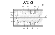
- FIG. 4B shows another example of the crawler body forming mold 10 used in the crawler body forming process in the method of manufacturing the rubber crawler 1 according to the embodiment of the present invention.
- the crawler body forming mold 20 in FIG. 4B employs a cooling pipe 14 instead of the heat insulating materials 23 and 24 as heat insulating means.
- the cooling pipe 14 is embedded in the upper mold 21 and the lower mold 22.
- the unvulcanized rubber RR in the cavity C2 can be vulcanized so that the planned location where the drive protrusions 4 and lugs 5 are arranged remains in a semi-vulcanized state.
- a belt-shaped or annular crawler having semi-vulcanized surfaces 2c and 2d as shown in FIG.
- the number of cooling pipes 14 is illustratively six, but the number of cooling pipes 14 is arbitrary according to the number of lugs 5.
- the manufacturing method of the rubber crawler 1 according to the present embodiment is such that the semi-vulcanized surface of the rubber projection (in this embodiment, the semi-vulcanized surface 4a of the drive projection 4 and the semi-vulcanized surface 5a of the lug 5) are crawler bodies.
- the rubber protrusions are arranged on the crawler body in accordance with the two semi-vulcanized surfaces (in this embodiment, the semi-vulcanized surface 2c and the semi-vulcanized surface 2d), and then the rubber protrusions and the crawler body 2 are vulcanized to integrate them.
- a rubber crawler forming step is provided.
- the rubber crawler forming step After the rubber projection forming step and the crawler body forming step, after obtaining the drive projection 4 having the semi-vulcanized surface 4a, the lug 5 having the semi-vulcanized surface 5a, and the crawler body 2 having the semi-vulcanized surfaces 2c, 2d, That is, after the rubber protrusion forming step and the crawler body forming step are completed, the rubber crawler forming step is performed after these steps.
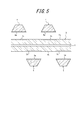
- the rubber crawler forming step is composed of two steps. First, as shown in FIG. 5, the semi-vulcanized surface 4a of the drive projection 4 and the semi-vulcanized surface 5a of the lug 5 are respectively provided as the first step.
- the rubber crawler 1 in a semi-vulcanized state is temporarily assembled by being disposed on the semi-vulcanized surfaces 2c and 2d of the crawler body 2.
- the semi-vulcanized surface 4a of the drive projection 4 and the semi-vulcanized surface 2c of the crawler body 2 and the semi-vulcanized surface 5a of the lug 5 and the semi-vulcanized surface 2d of the crawler body 2 are temporarily assembled. Are vulcanized so that the drive protrusion 4 and the lug 5 are integrated with the crawler body 2 by vulcanization adhesion.
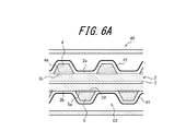
- 6A is an example of the second step of the rubber crawler forming step in the method of manufacturing a rubber crawler according to an embodiment of the present invention that can be used for manufacturing the rubber crawler of FIG.
- vulcanizing for vulcanizing the semi-vulcanized surface 4a and the semi-vulcanized surface 2c of the crawler body 2 and the semi-vulcanized surface 5a of the lug 5 and the semi-vulcanized surface 2d of the crawler body 2 with the vulcanizing can 40. It is principal part sectional drawing.
- the vulcanizing can 40 has a closed space (space) C3 that can be controlled at high temperature (temperature higher than normal temperature, preferably 130 ° C or higher) and high pressure (pressure higher than normal pressure, preferably 5 MPa or higher).
- This is an apparatus for vulcanizing unvulcanized rubber.
- heating for example, steam heat can be used.
- the upper limit values of the temperature and pressure in the sealed space C3 can be appropriately set within a range that does not affect the performance of the rubber crawler 1 after vulcanization molding.
- the drive protrusion 4 and the lug 5 are disposed on the crawler body 2 and temporarily assembled as a semi-vulcanized rubber crawler 1, and then the temporarily assembled semi-vulcanized rubber crawler. 1 is placed in the envelope 41 and is fixed by reducing the pressure in the envelope 41. Then, the fixed temporarily assembled rubber crawler 1 is placed in the sealed space C3 of the vulcanizing can 40 and vulcanized.
- the semi-vulcanized surface 4a of the temporarily assembled drive projection 4 and the semi-vulcanized surface 2c of the crawler body 2 are vulcanized and bonded, so that the drive projection 4 and the crawler body 2 are integrated.
- the lug 5 and the crawler body 2 can be integrated by vulcanizing and bonding the semi-vulcanized surface 5 of the temporarily assembled lug 5 and the semi-vulcanized surface 2d of the crawler body 2. Can do. Thereby, the vulcanization molding of the rubber crawler 1 having the drive protrusion 4 and the lug 5 is completed.
- the vulcanization of the semi-vulcanized surface 4a of the drive projection 4 and the semi-vulcanized surface 2c of the crawler body 2 and the semi-vulcanized surface 5a of the lug 5 and the semi-vulcanized surface 2d of the crawler body 2 is performed by adjusting the temperature of the heating means H. For example, by adjusting the temperature between 160 ° C. and 180 ° C., for example, it is achieved by pressure heating for about 2 hours.
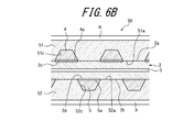
- the rubber crawler forming die 50 has an upper die 51 that forms the inner peripheral surface side shape of the rubber crawler 1 and a lower die 52 that forms the outer peripheral surface side shape of the rubber crawler 1.
- an upper die 51 that forms the inner peripheral surface side shape of the rubber crawler 1
- a lower die 52 that forms the outer peripheral surface side shape of the rubber crawler 1.
- a recess 51c for arranging the semi-vulcanized drive protrusion 4 formed in the rubber protrusion forming step is provided on the mating surface 51a of the upper side 51.
- the mating surface 52a of the lower mold 52 is provided with a recess 52c for placing the semi-vulcanized lug 5 formed in the rubber protrusion forming step as shown in the figure.
- the semi-vulcanized crawler main body 2 formed in the crawler main body forming step can be disposed between the upper die 51 and the lower die 52.
- the upper mold 51 is made of metal such as iron or aluminum alloy, and a heating means H is provided on the upper mold 51.
- the heating means H vulcanizes the semi-vulcanized surface 4 a of the drive protrusion 4 and the semi-vulcanized surface 2 c of the crawler body 2 from the upper mold 51.
- the lower mold 52 is made of a metal such as iron or an aluminum alloy, and a heating means H is provided on the lower side thereof.
- the heating means H vulcanizes the semi-vulcanized surface 5 a of the lug 5 and the semi-vulcanized surface 2 d of the crawler body 2 from the lower mold 52. Thereby, the drive protrusion 4 and the lug 5 can be integrally vulcanized and bonded to the crawler body 2.
- the first step of temporarily assembling the semi-vulcanized surface 4 a of the drive protrusion 4 and the semi-vulcanized surface 5 a of the lug 5 to the semi-vulcanized surfaces 2 c and 2 d of the crawler body 2 is formed in the upper mold 51.
- the semi-vulcanized drive protrusion 4 formed in the rubber protrusion forming process is disposed in the recess 51c, and the semi-vulcanized formed in the rubber protrusion forming process in the recess 52c formed in the lower mold 52.
- the mold is closed by interposing the semi-vulcanized crawler body 2 formed in the crawler body forming step between the upper mold 51 and the lower mold 52. .
- the heating protrusion H is used to close the driving protrusion 4 between the upper mold 51 and the lower mold 52.
- the semi-vulcanized surface 4a and the semi-vulcanized surface 2c of the crawler body 2 and the semi-vulcanized surface 5a of the lug 5 and the semi-vulcanized surface 2d of the crawler body 2 are vulcanized and bonded.
- the first step and the second step can be executed as a series of operations.
- the crawler body 2 is molded independently of the drive protrusion 4 and the lug 5 as shown in FIGS. 3B and 4B.
- the recesses for forming the drive protrusions 4 and the lugs 5, that is, the unvulcanized rubber RR arranged in the cavity C2 flows greatly. There is no part. For this reason, the deformation
- the drive protrusion 4 is vulcanized and molded so that a part of the surface of the drive protrusion 4 becomes a semi-vulcanized surface 4a.
- the lug 5 is vulcanized and molded so that a part of the surface of the lug 5 becomes the semi-vulcanized surface 5a, and these are formed on the semi-vulcanized surfaces 2c and 2d of the crawler body 2 as shown in FIGS. 6A and 6B.
- the rubber crawler forming process is performed in the semi-vulcanized surface 4a of the drive protrusion 4 in the sealed space C3 that can be controlled at high temperature and high pressure.
- the semi-vulcanized surface 2c of the crawler body 2 and the semi-vulcanized surface 5a of the lug 5 and the semi-vulcanized surface 2d of the crawler main body 2 are vulcanized.
- a mold for integrating the drive protrusion 4 and the lug 5 and the crawler body 2 such as the rubber crawler forming mold 50 shown in FIG. 6B becomes unnecessary.
- the production capacity production amount per hour
- the production capacity can be improved by vulcanizing a plurality of semi-vulcanized rubber crawlers 1 at a time, thereby reducing the manufacturing cost. be able to.
- the heat insulating means used in the rubber protrusion forming process and the crawler body forming process is exemplified by a heat insulating material and a cooling pipe
- the heat insulating performance can be exhibited so that a part of the surface of the rubber protrusion remains in a semi-vulcanized state. Anything is acceptable.
- a space can be provided in the upper mold and the lower mold of the crawler body forming mold, and the space can be used as a heat insulating layer.
- the heat insulating effect can be enhanced.
- the heat insulating means is locally provided at the planned arrangement place where the driving protrusion 4 and the lug 5 are arranged, but the crawler main body inner peripheral side forming surface 21 a and the lower mold of the upper mold 21.
- the crawler body outer peripheral side forming surface 22a can be embedded in the entire surface (preferably, a position closer to the inner peripheral side forming surface 21a and the outer peripheral side forming surface 22a).
- the upper mold 21 and the lower mold 22 are divided into a plurality of divided molds so that the arrangement of the heat insulating means can be appropriately changed. It is also possible to configure. Furthermore, the rubber projection forming mold 10, the crawler body forming mold 20, and the rubber crawler forming mold 50 can be configured so that the upper mold and the lower mold are arranged upside down.
- the present invention can be applied to a method of manufacturing a rubber crawler in which rubber protrusions are provided separately from the main body.
Landscapes
- Engineering & Computer Science (AREA)
- Mechanical Engineering (AREA)
- Physics & Mathematics (AREA)
- Health & Medical Sciences (AREA)
- Oral & Maxillofacial Surgery (AREA)
- Thermal Sciences (AREA)
- Chemical & Material Sciences (AREA)
- Combustion & Propulsion (AREA)
- Transportation (AREA)
- Heating, Cooling, Or Curing Plastics Or The Like In General (AREA)
Abstract
製造時に生じ得る、抗張体の変形を抑制できる、ゴムクローラの製造方法を提供する。 ゴムクローラ1の製造方法は、半加硫状態が残るように未加硫ゴムRRを加硫して、半加硫面4a,5aを有するゴム突起4,5を得る、工程と、半加硫状態が残るように、抗張体3が埋設された未加硫ゴムRRを加硫して、半加硫面2c,2dを有する本体2を得る、工程と、前記ゴム突起4,5を本体2に配置したのち、ゴム突起4,5および本体2を加硫することで一体化させる、工程と、を備える。
Description
本発明は、ゴムクローラの製造方法に関する。
従来のゴムクローラの製造方法には、抗張体の内周側と外周側とに、所定の長さの未加硫ゴムを添設し、これらを上型と下型とで挟持して加硫成形を行うことで帯状のゴムクローラを得たのち、未加硫のままのゴムクローラの長手方向端部を一体に加硫接着させることで環状のゴムクローラを得る方法がある(例えば、特許文献1参照)。
上記従来のゴムクローラの製造方法では、ゴム突起(例えば、駆動突起及びラグ)となる部分を含む未加硫ゴム(生ゴム)が配置された型を閉じることで、ゴム突起と本体が未加硫状態で一体に形作られたのち、この未加硫ゴムに圧力及び熱を加えることで、加硫済みのゴムクローラが形成されるが、このとき、未加硫ゴムは流動性を有している。流動性を有するゴムは、高圧部分から低圧部分に向かって流動する。低圧部分は主として、ゴムクローラの肉厚部分、すなわち、型内にゴム突起を形作って未加硫ゴムが配置される凹所である。したがって、未加硫ゴムを型閉じしてゴムクローラを一体に得ようとするとき、流動性を有するゴムは、ゴム突起が形作られる型内の凹所に向かって流動する。
このように流動するゴムに抗張体が押されると、当該抗張体に変形を生じさせる虞がある。
本発明の目的は、製造時に生じ得る、抗張体の変形を抑制することができる、ゴムクローラの製造方法を提供することである。
本発明に係る、ゴムクローラの製造方法は、一部の表面が半加硫状態に残るように未加硫ゴムを加硫して、半加硫面を有するゴム突起を得る、ゴム突起形成工程と、少なくとも前記ゴム突起が配置される配置予定箇所が半加硫状態に残るように、抗張体が埋設された未加硫ゴムを加硫して、半加硫面を有する本体を得る、本体形成工程と、前記ゴム突起形成工程および前記本体形成工程に次いで、前記ゴム突起の半加硫面を前記本体の半加硫面に合わせて前記ゴム突起を前記本体に配置したのち、前記ゴム突起および前記本体を加硫することで一体化させる、ゴムクローラ形成工程と、を備える。本発明に係る、ゴムクローラの製造方法によれば、製造時に生じ得る、抗張体の変形を抑制することができる。
本発明に係る、ゴムクローラの製造方法では、前記ゴムクローラ形成工程は、高温・高圧に制御可能な空間内で前記ゴム突起および前記本体を加硫することが好ましい。この場合、ゴム突起および本体を一体化させるための型が不要になる。
本発明によれば、製造時に生じ得る、抗張体の変形を抑制することができる、ゴムクローラの製造方法を提供することができる。
以下、図面を参照して、本発明であるゴムクローラの製造方法の様々な実施形態を説明する。
図1中、符号1は、本発明のゴムクローラの製造方法によって製造可能なゴムクローラである。ゴムクローラ1は、加硫ゴムからなる無端帯状のクローラ本体(本体)2を有している。図2Bに示すように、クローラ本体2には、抗張体(例えば、スチールコード)3が埋設されている。抗張体3はクローラ本体2の周方向に延在し、互いにクローラ本体の幅方向(図2Bでは、紙面表裏方向)に間隔を置いて複数配置されている。クローラ本体における抗張体3の内外周側には、抗張体3の他に、補強層等を埋設することができる。
符号4は、クローラ本体2の内周面2aに設けられた駆動突起(ゴム突起)である。駆動突起4は、加硫ゴムからなる。駆動突起4は、図示しないスプロケットと噛み合うことで、ゴムクローラ1の回転を生起させる。ゴムクローラ1では、図2Bに示すように、複数の駆動突起4がクローラ本体2の周方向(図中、左右方向)に間隔を置いて配置されている。駆動突起4の形状および配置は、適宜変更することができる。
図1中、符号5は、クローラ本体2の外周面2bに設けられたラグ(ゴム突起)である。ラグ5は、加硫ゴムからなる。ゴムクローラ1では、図2Cに示すように、複数のラグ5がクローラ本体2の周方向に間隔を置いて配置されている。ゴムクローラ1では、複数のラグ5をクローラ本体2の周方向に互い違いに配置している。ラグ5の形状および配置は、適宜変更することができる。
次に、本発明の一実施形態に係るゴムクローラ1の製造方法について説明する。以下、同実施形態に係るゴムクローラ1の製造方法については、図面上下の方向を上下方向として説明する。
本実施形態に係るゴムクローラ1の製造方法は、一部の表面が半加硫状態に残るように未加硫ゴムRRを加硫して、半加硫面を有するゴム突起(本実施形態では、駆動突起4及びラグ5)を得る、ゴム突起形成工程を備えている。
図3A中、符号10は、本発明の一実施形態に係るゴムクローラ1の製造方法における、ゴム突起形成工程で用いられる、一例のゴム突起形成型である。ゴム突起形成型10は、駆動突起4の内側形状を形作る上型11と、駆動突起4の外側形状を形作る下型12とを有し、図示のように、上型11の合せ面11aと下型12の合せ面12aとを合わせることで、駆動突起4を形成するためのキャビティC1が形成される。キャビティC1内には、未加硫ゴムRRが配置されている。
上型11は、鉄やアルミニウム合金等の金属からなり、その上側に加熱手段Hが設けられている。加熱手段Hは、上型11を通してキャビティC1内を上側から加熱する。下型12は、鉄やアルミニウム合金等の金属からなり、その下側に加熱手段Hが設けられている。加熱手段Hは、下型12を通してキャビティC1内を下側から加熱する。これにより、キャビティC1内は、2つの加熱手段Hによって加熱することができる。加熱手段Hには、例えば、蒸気圧や電気を利用した加熱器が挙げられる。
上型11はさらに、断熱手段として断熱材13を備えている。断熱材13は、加熱手段Hからの熱を遮断し、キャビティC1内の未加硫ゴムRRに対する上型11からの加熱を抑制する。断熱材13は、上型11に埋設されている。好適には、図3Aに示すように、断熱材13の表面13aが上型11の合せ面11aと同一の面となるように埋設する。加熱手段Hで加熱した場合、断熱材13の表面13aに接する未加硫ゴムRRは、上型11からの熱伝導が抑制されるため、断熱材13の表面13aに接する部分では半加硫の状態となる。断熱材としては、例えば、ポリテトラフルオロエチレン(PTFE)等のフッ素樹脂系断熱材やガラスクロス系断熱材が挙げられる。
駆動突起4は、ゴム突起形成型10内のキャビティC1に未加硫ゴムRRを配置して型閉じしたのち、加熱手段Hを用いて上型11および下型12を加熱することで形成することができる。このように、ゴム突起形成型10を用いれば、駆動突起4の一部の表面(この例では、クローラ本体2の内周面2aとの接合面)が半加硫状態に残るように、キャビティC1内の未加硫ゴムRRを加硫することができる。言い換えれば、ゴム突起形成型10を用いることで、図5に示すような、半加硫面4aを有する駆動突起4を得ることができる。ここで、半加硫状態とは、完全に加硫していないで加硫ができる余地を残した状態、言い換えれば、加硫接着ができる余地を残した状態をいう。すなわち、半加硫状態とは、生ゴムが加硫ゴムになる前の段階の状態をいい、未加硫状態も含む意味である。
また、ラグ5も、ゴム突起形成型10と同様のゴム突起形成型を用いて、当該ゴム突起形成型内のキャビティC1に未加硫ゴムRRを配置して型閉じしたのち、加熱手段Hを用いて上型11および下型12を加熱することで形成することができる。このように、ゴム突起形成型10と同様のゴム突起形成型を用いれば、駆動突起4と同様、ラグ5の一部の表面が半加硫状態に残るように、キャビティC1内の未加硫ゴムRRを加硫することができる。言い換えれば、ゴム突起形成型10と同様のゴム突起形成型を用いることで、図5に示すような、半加硫面5aを有するラグ5を得ることができる。
上述のとおり、ゴム突起形成工程では、ゴム突起形成型10内のキャビティC1に未加硫ゴムRRを配置して型閉じしたのち、加熱手段Hを用いて上型11および下型12を加熱することで、駆動突起4やラグ5等のゴム突起が形成される。未加硫ゴムRRの加硫は、加熱手段Hの温度を、例えば、160°C~180°Cの間に調整することで行い、半加硫状態は、断熱材13によって、上型11からキャビティC1内に伝達される温度が例えば、100°C以下になるようにすることで達成される。
また、本実施形態に係るゴムクローラ1の製造方法は、少なくともゴム突起(本実施形態では、駆動突起4及びラグ5)が配置される配置予定箇所が半加硫状態に残るように、抗張体3が埋設された未加硫ゴムRRを加硫して、半加硫面を有するクローラ本体2を得る、クローラ本体形成工程を備えている。
図3B中、符号20は、本実施形態に係るゴムクローラ1の製造方法における、クローラ本体形成工程(本体形成工程)で用いられる、一例のクローラ本体形成型である。以下、上述した構成と実質的に同一の部分は、同一符号をもってその説明を省略する。
クローラ本体形成型20は、クローラ本体2の内周側形状を形作る上型21と、クローラ本体2の外周側形状を形作る下型22とを有し、図示のように、上型21と下型22とで抗張体3を挟持しつつ上型21と下型22とを合わせることで、クローラ本体2を形成するためのキャビティC2が形成される。キャビティC2内には、抗張体3と、抗張体3の内周側(図面上側)に配置された、所定の長さを有する未加硫ゴムRRと、抗張体3の外周側(図面下側)に配置された、所定の長さを有する未加硫ゴムRRとが配置されている。
上型21は、鉄やアルミニウム合金等の金属からなり、その上側に加熱手段Hが設けられている。加熱手段Hは、上型21を通してキャビティC2内を上側から加熱する。下型22は、鉄やアルミニウム合金等の金属からなり、その下側に加熱手段Hが設けられている。加熱手段Hは、下型22を通してキャビティC2内を下側から加熱する。これにより、キャビティC2内は、2つの加熱手段Hによって加熱することができる。
上型21はさらに、断熱手段として断熱材23を備えている。断熱材23は、加熱手段Hからの熱を遮断し、キャビティC2内の未加硫ゴムRRに対する上型21からの加熱を抑制する。断熱材23は、少なくとも駆動突起4が配置される配置予定箇所に配置されている。断熱材23は、上型21に埋設されている。好適には、図3Bに示すように、断熱材23の表面23aが、上型21におけるクローラ本体2の内周面2aを形作るクローラ本体内周側形成面21aと同一の面となるように、断熱材23を埋設する。加熱手段Hで加熱した場合、未加硫ゴムRRは、断熱材23の表面23aに接する箇所で上型21からの熱伝導が抑制されるため、断熱材23の表面23aに接する部分では、クローラ本体2の内周面2aは局所的に、半加硫の状態となる。断熱材としては、断熱材13と同様、例えば、フッ素樹脂系断熱材やガラスクロス系断熱材が挙げられる。
下型22はさらに、断熱手段として断熱材24を備えている。断熱材24は、加熱手段Hからの熱を遮断し、キャビティC2内の未加硫ゴムRRに対する下型22からの加熱を抑制する。断熱材24は、少なくともラグ5が配置される配置予定箇所に配置されている。断熱材24は、下型22に埋設されている。好適には、図3Bに示すように、断熱材24の表面24aが、下型22におけるクローラ本体2の外周面2bを形作るクローラ本体外周側形成面22aと同一の面となるように、断熱材24を埋設する。加熱手段Hで加熱した場合、未加硫ゴムRRは、断熱材24の表面24aに接する箇所で下型22からの熱伝導が抑制されるため、断熱材24の表面24aに接する部分では、クローラ本体2の外周面2bは局所的に、半加硫の状態となる。断熱材24としては、断熱材13,23と同様、例えば、フッ素樹脂系断熱材やガラスクロス系断熱材が挙げられる。
帯状のクローラ本体2は、クローラ本体形成型20内のキャビティC2に、抗張体3が埋設された未加硫ゴムRRを配置して型閉じしたのち、加熱手段Hを用いて上型21および下型22を加熱することで形成することができる。このように、クローラ本体形成型20を用いれば、駆動突起4およびラグ5が配置される配置予定箇所が半加硫状態に残るように、キャビティC2内の未加硫ゴムRRを加硫することができる。言い換えれば、クローラ本体形成型20を用いることで、図5に示すように、内周面2a及び外周面2bにそれぞれ、局所的に、半加硫面2c,2dを有する、帯状のクローラ本体2を得ることができる。そして、クローラ本体形成型20で形成された、少なくとも1つの帯状のクローラ本体2を無端状に連結すれば、環状のクローラ本体2を形成することができる。
上述のとおり、本実施形態に係るゴムクローラの製造方法における、クローラ本体形成工程ではまず、クローラ本体形成型20内のキャビティC2に、抗張体3が埋設された未加硫ゴムRRを配置して型閉じしたのち、加熱手段Hを用いて上型21および下型22を加熱することで、少なくとも1つの帯状のクローラ本体2を形成する。未加硫ゴムRRの加硫は、加熱手段Hの温度を、例えば、160°C~180°Cの間に調整することで行い、半加硫状態は、断熱材23,24によって、上型21及び下型22からキャビティC2内に伝達される温度が例えば、70°C~80°Cになるようにすることで達成される。
次いで、ここでのクローラ本体形成工程では、クローラ本体形成型20を用いて形成された、少なくとも1つの帯状のクローラ本体2を無端状に連結することで、所望する、環状のクローラ本体2が形成される。なお、環状のクローラ本体2は、クローラ本体形成型20を無端状のキャビティC2が形成される円形のクローラ本体形成型とすることで、クローラ本体形成型のみで形成することも可能である。すなわち、クローラ本体形成工程は、ゴム突起形成工程と同様、クローラ本体形成型のみを用いて実行することも可能である。
また、図1のゴムクローラの製造に用いることが可能な、本実施形態に係るゴムクローラの製造方法として、ゴム突起形成工程では、積極的に断熱を行うことも可能である。図4Aには、本発明の一実施形態に係るゴムクローラ1の製造方法における、ゴム突起形成工程で用いられる、他の例のゴム突起形成型10を示す。図4Aのゴム突起形成型10は、断熱手段として、断熱材13に代えて、冷却管14を採用している。冷却管14は、水等の液体を通すことで、上型11を局所的に冷却することができる。冷却管14は、上型11に埋設されている。好適には、可能な限り、キャビティC1を含む領域であって上型11の合せ面11aに近い位置に配置する。この場合、駆動突起4やラグ5の一部の表面が半加硫状態に残るように、キャビティC1内の未加硫ゴムRRを加硫することができる。言い換えれば、上型11の冷却により加熱手段Hからの熱を積極的に遮断することで、図5に示すような、半加硫面4aを有する駆動突起4や半加硫面5aを有するラグ5を得ることができる。なお、図4Aでは、冷却管14を例示的に4本としているが、冷却管14の本数は、駆動突起4の個数に合わせて任意である。
同様に、図4Bには、本発明の一実施形態に係るゴムクローラ1の製造方法における、クローラ本体形成工程で用いられる、他の例のクローラ本体形成型10を示す。図4Bのクローラ本体形成型20は、断熱手段として、断熱材23,24に代えて、冷却管14を採用している。冷却管14は、上型21及び下型22に埋設されている。この場合、駆動突起4及びラグ5が配置される配置予定箇所が半加硫状態に残るように、キャビティC2内の未加硫ゴムRRを加硫することができる。言い換えれば、上型21及び下型22の冷却により加熱手段Hからの熱を積極的に遮断することで、図5に示すような、半加硫面2c,2dを有する、帯状又は環状のクローラ本体2を得ることができる。なお、図4Bでは、冷却管14を例示的に6本としているが、冷却管14の本数は、ラグ5の個数に合わせて任意である。
さらに、本実施形態に係るゴムクローラ1の製造方法は、ゴム突起の半加硫面(本実施形態では、駆動突起4の半加硫面4a及びラグ5の半加硫面5a)をクローラ本体2の半加硫面(本実施形態では、半加硫面2cおよび半加硫面2d)に合わせてゴム突起をクローラ本体に配置したのち、ゴム突起およびクローラ本体2を加硫することで一体化させる、ゴムクローラ形成工程を備えている。
ゴム突起形成工程およびクローラ本体形成工程を経て、半加硫面4aを有する駆動突起4及び半加硫面5aを有するラグ5並びに半加硫面2c,2dを有するクローラ本体2を得たのち、すなわち、ゴム突起形成工程およびクローラ本体形成工程が完了したのちは、これらの工程に次いで、ゴムクローラ形成工程が行われる。
本実施形態では、ゴムクローラ形成工程は2つの工程からなり、まず、第1工程として、図5に示すように、駆動突起4の半加硫面4aおよびラグ5の半加硫面5aをそれぞれ、クローラ本体2の半加硫面2c,2dに配置して、半加硫状態のゴムクローラ1の仮組みを行う。
次いで、第2工程として、仮組みされた、駆動突起4の半加硫面4aおよびクローラ本体2の半加硫面2c並びにラグ5の半加硫面5aおよびクローラ本体2の半加硫面2dをそれぞれ、加硫することで、駆動突起4およびラグ5をクローラ本体2に加硫接着により一体化させる。
図6Aは、図1のゴムクローラの製造に用いることが可能な、本発明の一実施形態に係るゴムクローラの製造方法における、ゴムクローラ形成工程の第2工程の一例であって、弾性突起4の半加硫面4aおよびクローラ本体2の半加硫面2c並びにラグ5の半加硫面5a及びクローラ本体2の半加硫面2dを加硫缶40で加硫する工程を説明するための要部断面図である。
加硫缶40は、高温(常温よりも高い温度、好ましくは、130°C以上)・高圧(常圧よりも高い圧力、好ましくは、5MPa以上)に制御可能な密閉空間(空間)C3を有して未加硫ゴムを加硫する装置である。加熱には、例えば、蒸気熱を用いることができる。なお、密閉空間C3内の温度及び圧力の上限値は、加硫成形後のゴムクローラ1の性能に影響を及ぼさない範囲で、適宜、設定することができる。
加硫缶40を用いる場合には、駆動突起4およびラグ5をクローラ本体2に配置して半加硫状態のゴムクローラ1として仮組みしたのち、この仮組みされた半加硫状態のゴムクローラ1を、エンベロープ41内に入れ、エンベロープ41内を減圧することで固定する。そして固定された仮組みのゴムクローラ1を加硫缶40の密閉空間C3に入れて加硫を行う。加硫缶40内では、仮組みされた駆動突起4の半加硫面4aとクローラ本体2の半加硫面2cとが加硫接着されることで、駆動突起4とクローラ本体2とを一体化させることができるとともに、仮組みされたラグ5の半加硫面5とクローラ本体2の半加硫面2dが加硫接着されることで、ラグ5とクローラ本体2とを一体化させることができる。これにより、駆動突起4およびラグ5を有するゴムクローラ1の加硫成形が完了する。駆動突起4の半加硫面4a及びクローラ本体2の半加硫面2c並びにラグ5の半加硫面5aとクローラ本体2の半加硫面2dの加硫は、加熱手段Hの温度を、例えば、160°C~180°Cの間に調整することで行い、例えば、約2時間の圧力加熱によって達成される。
また、図1のゴムクローラの製造に用いることが可能な、本発明のゴムクローラの製造方法における、ゴムクローラ形成工程の第2工程の他の例として、ゴムクローラ形成型50を用いて型成形を行うことも可能である。
図6B中、ゴムクローラ形成型50は、ゴムクローラ1の内周面側形状を形作る上型51と、ゴムクローラ1の外周面側形状を形作る下型52とを有している。なお、以下の説明において、上述した構成と実質的に同一の部分は同一符号をもってその説明を省略する。
上側51の合せ面51aには、図示のように、ゴム突起形成工程で形成された半加硫状態の駆動突起4を配置するための凹所51cが設けられている。同様に、下型52の合せ面52aには、図示のように、ゴム突起形成工程で形成された半加硫状態のラグ5を配置するための凹所52cが設けられている。さらに、ゴムクローラ形成型50は、上型51と下型52との間で、クローラ本体形成工程で形成された半加硫状態のクローラ本体2を配置することができる。
上型51は、鉄やアルミニウム合金等の金属からなり、その上側に加熱手段Hが設けられている。加熱手段Hは、上型51から駆動突起4の半加硫面4aおよびクローラ本体2の半加硫面2cを加硫する。下型52は、鉄やアルミニウム合金等の金属からなり、その下側に加熱手段Hが設けられている。加熱手段Hは、下型52からラグ5の半加硫面5aおよびクローラ本体2の半加硫面2dを加硫する。これにより、駆動突起4及びラグ5をクローラ本体2に一体に加硫接着することができる。
この例では、駆動突起4の半加硫面4aおよびラグ5の半加硫面5aをクローラ本体2の半加硫面2c,2dに仮組みする第1工程は、上型51に形成された凹所51cに、ゴム突起形成工程で形成された半加硫状態の駆動突起4を配置するとともに、下型52に形成された凹所52cに、同じくゴム突起形成工程で形成された半加硫状態のラグ5を配置したのち、上型51と下型52との間に、クローラ本体形成工程で形成された、半加硫状態のクローラ本体2を介在させて型閉じすることで実行される。
次いで、駆動突起4及びラグ5をクローラ本体2に一体に加硫する第2工程は、加熱手段Hを用いて、上型51と下型52との間に型閉じされた、駆動突起4の半加硫面4a及びクローラ本体2の半加硫面2c並びにラグ5の半加硫面5a及びクローラ本体2の半加硫面2dを加硫接着することで実行される。このように、ゴムクローラ形成工程は、ゴムクローラ形成型50を用いることで、第1工程及び第2工程を一連の作業として実行することができる。
上述の本実施形態に係るゴムクローラ1の製造方法によれば、図3Bや図4Bに示すように、クローラ本体2は、駆動突起4及びラグ5とは別に、独立として成形される。この場合、クローラ本体形成型20の上型21及び下型22には、駆動突起4およびラグ5を形作るための凹所、すなわち、キャビティC2内に配置された未加硫ゴムRRが大きく流動する部分が存在しない。このため、流動する未加硫ゴムRRに抗張体3が押されることで、抗張体3に生じる変形を抑制することができる。したがって、上述の、ゴムクローラ1の製造方法によれば、製造時に生じ得る、抗張体3の変形を抑制することができる、ゴムクローラの製造方法を提供することができる。
加えて、ゴムクローラ1の製造方法によれば、図3Aや図4Aに示すように、駆動突起4の一部の表面が半加硫面4aとなるように駆動突起4を加硫成形するとともに、ラグ5の一部の表面が半加硫面5aとなるようにラグ5を加硫成形し、これらを、図6A,Bに示すように、クローラ本体2の半加硫面2c,2dで加硫して一体化することで、加硫ゴム同士の接着に必要な接着ゴムが不要になる。また、接着ゴム等の接着手段を塗布する必要がなくなることで、作業性に優れる。また、半加硫面同士を加硫接着させることで、接着ゴム品と対比して接着強度が高くなる。
特に、図6Aのように加硫缶40を用いたゴムクローラ1の製造方法では、ゴムクローラ形成工程は、高温・高圧に制御可能な密閉空間C3内で、駆動突起4の半加硫面4aおよびクローラ本体2の半加硫面2c並びにラグ5の半加硫面5a及びクローラ本体2の半加硫面2dを加硫している。この場合、図6Bに示すゴムクローラ形成型50のような、駆動突起4およびラグ5並びにクローラ本体2を一体化させるための型が不要になる。また、加硫缶40を用いれば、複数の半加硫状態のゴムクローラ1を一度に加硫することで、生産能力(時間当たりの生産量)を向上させることができ、製造コストを削減することができる。
上述したところは、本発明の実施形態の例示であって、特許請求の範囲の記載によれば、種々の変更が可能である。例えば、ゴム突起形成工程及びクローラ本体形成工程で用いられる断熱手段は、断熱材および冷却管を例にしたが、ゴム突起の一部の表面が半加硫状態に残るように断熱性能を発揮できるものであればよい。具体例としては、クローラ本体形成型の上型及び下型に、空間を設け、当該空間を断熱層とすることができる。更に空間を真空(大気圧よりも減圧させた状態を含む)とすると、断熱効果を高めることができる。また、クローラ本体形成型20では、駆動突起4及びラグ5が配置される配置予定箇所に対して局所的に断熱手段を設けたが、上型21のクローラ本体内周側形成面21a及び下型22のクローラ本体外周側形成面22aの全面(好適には、クローラ本体の内周側形成面21a及び外周側形成面22aにより近い位置)に埋設させることができる。また、クローラ本体形成型20では、上型21及び下型22を複数の分割型とすることで、断熱手段の配置を適宜変更できるようにしているが、上型21及び下型22は一体に構成することも可能である。さらに、ゴム突起形成型10、クローラ本体形成型20及びゴムクローラ形成型50は、上型及び下型の構成を上下反対にすることができる。
本発明は、ゴム突起を本体に別体として設けるゴムクローラの製造方法に採用することができる。
1;ゴムクローラ, 2;クローラ本体(本体), 2a;クローラ本体の内周面, 2b;クローラ本体の外周面, 2c;半加硫面, 2d;半加硫面, 3;抗張体, 4;駆動突起(ゴム突起), 4a;半加硫面, 5;ラグ(ゴム突起), 5a; 半加硫面, 10;ゴム突起形成型, 11;上型, 11a;上型の合せ面, 12;下型, 12a;下型の合せ面, 13;断熱材, 13a;断熱材の表面, 14;冷却管, 20;クローラ本体形成型, 21;上型, 21a;クローラ本体内周側形成面, 22;下型, 22a;クローラ本体外周側形成面, 23;断熱材, 23a;断熱材の表面, 24;断熱材, 24a;断熱材の表面, 40;加硫缶, 41;耐熱性シート, 50;ゴムクローラ形成型, 51;上型, 51a;上側の合せ面, 51c;凹所, 52;下型, 52a;下側の合せ面, 52c;凹所, C1;キャビティ, C2;キャビティ, C3;密閉空間(空間), H;加熱手段, RR;未加硫ゴム
Claims (2)
- 一部の表面が半加硫状態に残るように未加硫ゴムを加硫して、半加硫面を有するゴム突起を得る、ゴム突起形成工程と、
少なくとも前記ゴム突起が配置される配置予定箇所が半加硫状態に残るように、抗張体が埋設された未加硫ゴムを加硫して、半加硫面を有する本体を得る、本体形成工程と、
前記ゴム突起形成工程および前記本体形成工程に次いで、前記ゴム突起の半加硫面を前記本体の半加硫面に合わせて前記ゴム突起を前記本体に配置したのち、前記ゴム突起および前記本体を加硫することで一体化させる、ゴムクローラ形成工程と、
を備える、ゴムクローラの製造方法。 - 前記ゴムクローラ形成工程は、高温・高圧に制御可能な空間内で前記ゴム突起および前記本体を加硫する、請求項1に記載のゴムクローラの製造方法。
Priority Applications (2)
| Application Number | Priority Date | Filing Date | Title |
|---|---|---|---|
| US15/577,892 US10518492B2 (en) | 2015-06-24 | 2016-05-30 | Method for manufacturing rubber crawler |
| CN201680036206.7A CN107708953B (zh) | 2015-06-24 | 2016-05-30 | 橡胶履带的制造方法 |
Applications Claiming Priority (2)
| Application Number | Priority Date | Filing Date | Title |
|---|---|---|---|
| JP2015126659A JP6702663B2 (ja) | 2015-06-24 | 2015-06-24 | ゴムクローラの製造方法 |
| JP2015-126659 | 2015-06-24 |
Publications (1)
| Publication Number | Publication Date |
|---|---|
| WO2016208124A1 true WO2016208124A1 (ja) | 2016-12-29 |
Family
ID=57585405
Family Applications (1)
| Application Number | Title | Priority Date | Filing Date |
|---|---|---|---|
| PCT/JP2016/002616 Ceased WO2016208124A1 (ja) | 2015-06-24 | 2016-05-30 | ゴムクローラの製造方法 |
Country Status (4)
| Country | Link |
|---|---|
| US (1) | US10518492B2 (ja) |
| JP (1) | JP6702663B2 (ja) |
| CN (1) | CN107708953B (ja) |
| WO (1) | WO2016208124A1 (ja) |
Families Citing this family (1)
| Publication number | Priority date | Publication date | Assignee | Title |
|---|---|---|---|---|
| CN110871579A (zh) * | 2019-11-20 | 2020-03-10 | 浙江双箭橡胶股份有限公司 | 一种柔性输送带的制造方法 |
Citations (3)
| Publication number | Priority date | Publication date | Assignee | Title |
|---|---|---|---|---|
| JPH02261629A (ja) * | 1989-03-31 | 1990-10-24 | Sumitomo Electric Ind Ltd | 多層からなるゴム成形品の精密な成形方法 |
| JPH11129354A (ja) * | 1997-10-29 | 1999-05-18 | Bridgestone Corp | ゴムクロ−ラの製造方法 |
| JP2012228825A (ja) * | 2011-04-26 | 2012-11-22 | Bridgestone Corp | ゴムクローラの製造方法 |
Family Cites Families (26)
| Publication number | Priority date | Publication date | Assignee | Title |
|---|---|---|---|---|
| US4390214A (en) * | 1980-03-07 | 1983-06-28 | Dayco Corporation | Crawler track structure having wear surface |
| JP3802131B2 (ja) * | 1996-04-12 | 2006-07-26 | 株式会社ブリヂストン | ゴムクロ−ラの製造方法 |
| JP2002120231A (ja) * | 2000-10-17 | 2002-04-23 | Bridgestone Corp | ゴムクローラ製造用型 |
| US6818167B2 (en) * | 2000-10-17 | 2004-11-16 | Bridgestone Corporation | Method of manufacturing rubber crawler |
| AU2001262735A1 (en) | 2000-10-17 | 2002-04-29 | Bridgestone Corporation | Rubber crawler producing method |
| JP2003340934A (ja) | 2002-05-30 | 2003-12-02 | Mitsuboshi Belting Ltd | Vリブドベルトの製造方法およびvリブドベルト |
| JP2004076927A (ja) | 2002-06-20 | 2004-03-11 | Mitsuboshi Belting Ltd | Vリブドベルト及びその製造方法 |
| JP4256204B2 (ja) | 2002-06-28 | 2009-04-22 | 三ツ星ベルト株式会社 | 伝動ベルトの製造方法 |
| JP2004034352A (ja) | 2002-06-28 | 2004-02-05 | Mitsuboshi Belting Ltd | 動力伝動ベルトの製造方法 |
| JP3764413B2 (ja) | 2002-09-27 | 2006-04-05 | 三ツ星ベルト株式会社 | 伝動ベルトの製造方法 |
| JP4329925B2 (ja) | 2003-02-21 | 2009-09-09 | 三ツ星ベルト株式会社 | 伝動ベルトの製造方法 |
| JP4362308B2 (ja) | 2003-04-17 | 2009-11-11 | 三ツ星ベルト株式会社 | Vリブドベルトの製造方法 |
| JP4444800B2 (ja) | 2004-03-03 | 2010-03-31 | 住友ゴム工業株式会社 | 弾性履帯の製造方法及びこれを用いた加硫成形装置 |
| JP2006007450A (ja) | 2004-06-23 | 2006-01-12 | Mitsuboshi Belting Ltd | 伝動ベルトの製造方法と伝動ベルト |
| JP2006009946A (ja) | 2004-06-25 | 2006-01-12 | Mitsuboshi Belting Ltd | 伝動ベルトの製造方法 |
| JP2008213145A (ja) | 2006-06-29 | 2008-09-18 | Mitsuboshi Belting Ltd | 伝動ベルトの製造方法と伝動ベルト |
| JP5112744B2 (ja) | 2006-06-29 | 2013-01-09 | 三ツ星ベルト株式会社 | 伝動ベルトの製造方法 |
| JP2008044151A (ja) | 2006-08-11 | 2008-02-28 | Mitsuboshi Belting Ltd | 伝動ベルトの製造方法 |
| JP2008100365A (ja) | 2006-10-17 | 2008-05-01 | Mitsuboshi Belting Ltd | 伝動ベルトの製造方法 |
| JP4896753B2 (ja) | 2007-01-31 | 2012-03-14 | 三ツ星ベルト株式会社 | 伝動ベルトの製造方法 |
| JP2008213144A (ja) | 2007-02-07 | 2008-09-18 | Mitsuboshi Belting Ltd | 伝動ベルトの製造方法 |
| JP2008265031A (ja) | 2007-04-16 | 2008-11-06 | Mitsuboshi Belting Ltd | 伝動ベルトの製造方法 |
| JP2009196135A (ja) | 2008-02-20 | 2009-09-03 | Mitsuboshi Belting Ltd | 加硫ベルトスリーブの製造方法 |
| US8834668B2 (en) * | 2008-11-19 | 2014-09-16 | The Boeing Company | Staged cocuring of composite structures |
| JP5667845B2 (ja) * | 2010-11-09 | 2015-02-12 | 住友ゴム工業株式会社 | 加硫成形装置 |
| JP6224886B2 (ja) | 2012-11-12 | 2017-11-01 | 三ツ星ベルト株式会社 | 伝動ベルト及びその製造方法 |
-
2015
- 2015-06-24 JP JP2015126659A patent/JP6702663B2/ja active Active
-
2016
- 2016-05-30 US US15/577,892 patent/US10518492B2/en active Active
- 2016-05-30 WO PCT/JP2016/002616 patent/WO2016208124A1/ja not_active Ceased
- 2016-05-30 CN CN201680036206.7A patent/CN107708953B/zh not_active Expired - Fee Related
Patent Citations (3)
| Publication number | Priority date | Publication date | Assignee | Title |
|---|---|---|---|---|
| JPH02261629A (ja) * | 1989-03-31 | 1990-10-24 | Sumitomo Electric Ind Ltd | 多層からなるゴム成形品の精密な成形方法 |
| JPH11129354A (ja) * | 1997-10-29 | 1999-05-18 | Bridgestone Corp | ゴムクロ−ラの製造方法 |
| JP2012228825A (ja) * | 2011-04-26 | 2012-11-22 | Bridgestone Corp | ゴムクローラの製造方法 |
Also Published As
| Publication number | Publication date |
|---|---|
| JP2017007576A (ja) | 2017-01-12 |
| CN107708953A (zh) | 2018-02-16 |
| JP6702663B2 (ja) | 2020-06-03 |
| US10518492B2 (en) | 2019-12-31 |
| US20180290410A1 (en) | 2018-10-11 |
| CN107708953B (zh) | 2019-12-10 |
Similar Documents
| Publication | Publication Date | Title |
|---|---|---|
| JP5603385B2 (ja) | 弾性クローラの製造方法および弾性クローラ製造用の加硫成形金型 | |
| KR101638518B1 (ko) | 타이어 제조용 가류 금형 | |
| KR101150799B1 (ko) | 트레드 몰드 세그먼트, 이를 포함하는 타이어 가류금형, 및 타이어 가류금형의 조립방법 | |
| CN112265195A (zh) | 一种中空带织物橡胶密封件的成型方法 | |
| JPWO2002032640A1 (ja) | ゴムクローラの製造方法 | |
| WO2016208124A1 (ja) | ゴムクローラの製造方法 | |
| JP5667845B2 (ja) | 加硫成形装置 | |
| JP5325703B2 (ja) | ビード部材の製造方法及び製造装置 | |
| JP6218562B2 (ja) | 成形用部材 | |
| JP2008183818A (ja) | 熱可塑性部材および熱硬化性部材からなる複合体の成形方法 | |
| JP4369277B2 (ja) | 中子製造用金型、及び、中子製造方法 | |
| JP2001038818A (ja) | ゴムクローラの製造方法および加硫成形金型 | |
| JP4106903B2 (ja) | 滑り支承部材の製造方法 | |
| JP2004249701A (ja) | 爆発防止タイヤの製造方法 | |
| JP2001047436A (ja) | ゴムクローラの製造方法 | |
| RU2443553C1 (ru) | Способ изготовления резинофторопластового комбинированного уплотнения | |
| JP4406922B2 (ja) | タイヤ加硫方法及びその装置 | |
| CN215791902U (zh) | 一种用于轮胎硫化的双层硫化模具 | |
| JP7577217B2 (ja) | 成型方法 | |
| JP7591148B2 (ja) | 成型方法及び金型 | |
| JP6605295B2 (ja) | ゴムクローラ及び該ゴムクローラの製造方法 | |
| JP5706224B2 (ja) | タイヤ製造方法及びタイヤ | |
| JP2001341206A (ja) | プレート式熱交換器用ガスケットの製造方法及びそのガスケット | |
| JP4374257B2 (ja) | 接続用金型および長尺体接続方法 | |
| JPH04259541A (ja) | 空気入りタイヤの製造方法 |
Legal Events
| Date | Code | Title | Description |
|---|---|---|---|
| 121 | Ep: the epo has been informed by wipo that ep was designated in this application |
Ref document number: 16813900 Country of ref document: EP Kind code of ref document: A1 |
|
| WWE | Wipo information: entry into national phase |
Ref document number: 15577892 Country of ref document: US |
|
| NENP | Non-entry into the national phase |
Ref country code: DE |
|
| 122 | Ep: pct application non-entry in european phase |
Ref document number: 16813900 Country of ref document: EP Kind code of ref document: A1 |