WO2016181961A1 - 台数制御装置、エネルギー供給システム、台数制御方法及びプログラム - Google Patents
台数制御装置、エネルギー供給システム、台数制御方法及びプログラム Download PDFInfo
- Publication number
- WO2016181961A1 WO2016181961A1 PCT/JP2016/063854 JP2016063854W WO2016181961A1 WO 2016181961 A1 WO2016181961 A1 WO 2016181961A1 JP 2016063854 W JP2016063854 W JP 2016063854W WO 2016181961 A1 WO2016181961 A1 WO 2016181961A1
- Authority
- WO
- WIPO (PCT)
- Prior art keywords
- heat source
- load
- exhaust heat
- load range
- maximum
- Prior art date
- Legal status (The legal status is an assumption and is not a legal conclusion. Google has not performed a legal analysis and makes no representation as to the accuracy of the status listed.)
- Ceased
Links
Images




Classifications
-
- F—MECHANICAL ENGINEERING; LIGHTING; HEATING; WEAPONS; BLASTING
- F25—REFRIGERATION OR COOLING; COMBINED HEATING AND REFRIGERATION SYSTEMS; HEAT PUMP SYSTEMS; MANUFACTURE OR STORAGE OF ICE; LIQUEFACTION SOLIDIFICATION OF GASES
- F25B—REFRIGERATION MACHINES, PLANTS OR SYSTEMS; COMBINED HEATING AND REFRIGERATION SYSTEMS; HEAT PUMP SYSTEMS
- F25B27/00—Machines, plants or systems, using particular sources of energy
- F25B27/02—Machines, plants or systems, using particular sources of energy using waste heat, e.g. from internal-combustion engines
-
- F—MECHANICAL ENGINEERING; LIGHTING; HEATING; WEAPONS; BLASTING
- F24—HEATING; RANGES; VENTILATING
- F24F—AIR-CONDITIONING; AIR-HUMIDIFICATION; VENTILATION; USE OF AIR CURRENTS FOR SCREENING
- F24F11/00—Control or safety arrangements
- F24F11/89—Arrangement or mounting of control or safety devices
-
- F—MECHANICAL ENGINEERING; LIGHTING; HEATING; WEAPONS; BLASTING
- F25—REFRIGERATION OR COOLING; COMBINED HEATING AND REFRIGERATION SYSTEMS; HEAT PUMP SYSTEMS; MANUFACTURE OR STORAGE OF ICE; LIQUEFACTION SOLIDIFICATION OF GASES
- F25B—REFRIGERATION MACHINES, PLANTS OR SYSTEMS; COMBINED HEATING AND REFRIGERATION SYSTEMS; HEAT PUMP SYSTEMS
- F25B15/00—Sorption machines, plants or systems, operating continuously, e.g. absorption type
- F25B15/02—Sorption machines, plants or systems, operating continuously, e.g. absorption type without inert gas
- F25B15/04—Sorption machines, plants or systems, operating continuously, e.g. absorption type without inert gas the refrigerant being ammonia evaporated from aqueous solution
-
- F—MECHANICAL ENGINEERING; LIGHTING; HEATING; WEAPONS; BLASTING
- F25—REFRIGERATION OR COOLING; COMBINED HEATING AND REFRIGERATION SYSTEMS; HEAT PUMP SYSTEMS; MANUFACTURE OR STORAGE OF ICE; LIQUEFACTION SOLIDIFICATION OF GASES
- F25B—REFRIGERATION MACHINES, PLANTS OR SYSTEMS; COMBINED HEATING AND REFRIGERATION SYSTEMS; HEAT PUMP SYSTEMS
- F25B27/00—Machines, plants or systems, using particular sources of energy
-
- F—MECHANICAL ENGINEERING; LIGHTING; HEATING; WEAPONS; BLASTING
- F25—REFRIGERATION OR COOLING; COMBINED HEATING AND REFRIGERATION SYSTEMS; HEAT PUMP SYSTEMS; MANUFACTURE OR STORAGE OF ICE; LIQUEFACTION SOLIDIFICATION OF GASES
- F25B—REFRIGERATION MACHINES, PLANTS OR SYSTEMS; COMBINED HEATING AND REFRIGERATION SYSTEMS; HEAT PUMP SYSTEMS
- F25B27/00—Machines, plants or systems, using particular sources of energy
- F25B27/002—Machines, plants or systems, using particular sources of energy using solar energy
- F25B27/007—Machines, plants or systems, using particular sources of energy using solar energy in sorption type systems
-
- F—MECHANICAL ENGINEERING; LIGHTING; HEATING; WEAPONS; BLASTING
- F25—REFRIGERATION OR COOLING; COMBINED HEATING AND REFRIGERATION SYSTEMS; HEAT PUMP SYSTEMS; MANUFACTURE OR STORAGE OF ICE; LIQUEFACTION SOLIDIFICATION OF GASES
- F25B—REFRIGERATION MACHINES, PLANTS OR SYSTEMS; COMBINED HEATING AND REFRIGERATION SYSTEMS; HEAT PUMP SYSTEMS
- F25B49/00—Arrangement or mounting of control or safety devices
- F25B49/04—Arrangement or mounting of control or safety devices for sorption type machines, plants or systems
- F25B49/043—Operating continuously
-
- Y—GENERAL TAGGING OF NEW TECHNOLOGICAL DEVELOPMENTS; GENERAL TAGGING OF CROSS-SECTIONAL TECHNOLOGIES SPANNING OVER SEVERAL SECTIONS OF THE IPC; TECHNICAL SUBJECTS COVERED BY FORMER USPC CROSS-REFERENCE ART COLLECTIONS [XRACs] AND DIGESTS
- Y02—TECHNOLOGIES OR APPLICATIONS FOR MITIGATION OR ADAPTATION AGAINST CLIMATE CHANGE
- Y02A—TECHNOLOGIES FOR ADAPTATION TO CLIMATE CHANGE
- Y02A30/00—Adapting or protecting infrastructure or their operation
- Y02A30/27—Relating to heating, ventilation or air conditioning [HVAC] technologies
- Y02A30/274—Relating to heating, ventilation or air conditioning [HVAC] technologies using waste energy, e.g. from internal combustion engine
-
- Y—GENERAL TAGGING OF NEW TECHNOLOGICAL DEVELOPMENTS; GENERAL TAGGING OF CROSS-SECTIONAL TECHNOLOGIES SPANNING OVER SEVERAL SECTIONS OF THE IPC; TECHNICAL SUBJECTS COVERED BY FORMER USPC CROSS-REFERENCE ART COLLECTIONS [XRACs] AND DIGESTS
- Y02—TECHNOLOGIES OR APPLICATIONS FOR MITIGATION OR ADAPTATION AGAINST CLIMATE CHANGE
- Y02B—CLIMATE CHANGE MITIGATION TECHNOLOGIES RELATED TO BUILDINGS, e.g. HOUSING, HOUSE APPLIANCES OR RELATED END-USER APPLICATIONS
- Y02B30/00—Energy efficient heating, ventilation or air conditioning [HVAC]
- Y02B30/62—Absorption based systems
- Y02B30/625—Absorption based systems combined with heat or power generation [CHP], e.g. trigeneration
Definitions
- the present invention relates to a number control device, an energy supply system, a number control method, and a program.
- This application claims priority on May 13, 2015 based on Japanese Patent Application No. 2015-097881 for which it applied to Japan, and uses the content here.
- One of the heat source systems is a heat source system including an exhaust heat recovery type absorption chiller / heater.
- the exhaust heat recovery type absorption chiller / heater recovers exhaust heat from a gas engine or the like. Since the exhaust heat recovery type absorption chiller / heater recovers the exhaust heat, the amount of fuel gas supplied to the exhaust heat recovery type absorption chiller / heater can be reduced.
- Patent Document 1 discloses a technique related to a heat source system including an exhaust heat recovery type absorption chiller / heater.
- the gas absorption chiller / heater described in Patent Document 1 corresponds to an exhaust heat recovery type absorption chiller / heater, and the cold / hot water system corresponds to a heat source system.
- This cold / hot water system switches the number of operating gas absorption chiller / heater units by comparing the cost of fuel gas and the operating cost of auxiliary equipment. Specifically, in the cold / hot water system described in Patent Document 1, the cost of the fuel gas when the operation of one gas absorption chiller / heater is performed by both exhaust heat recovery and fuel gas is the second one. The operation of the second gas absorption chiller / heater is started at a load factor that exceeds the operation cost of the auxiliary machine when the operation of the gas absorption chiller / heater is performed by exhaust heat recovery.
- Patent Document 1 describes that the load factor provided by exhaust heat recovery varies depending on the operating load factor of the gas engine generator. However, Patent Document 1 does not show a method for dealing with factors other than the load factor covered by exhaust heat recovery. Even when the capability of the exhaust heat recovery type absorption chiller / heater changes due to factors other than the load factor provided by the exhaust heat recovery, it is desirable that the heat source system be operated efficiently.
- the present invention provides a number control device, an energy supply system, a number control method, and a program capable of efficiently operating a heat source system.
- the number control device is at least one first heat source that is an exhaust heat recovery type absorption chiller / heater that generates cold by receiving at least one of exhaust heat and fuel.
- the first heat source device in a heat source system comprising a second heat source device that is a heat source device other than the exhaust heat recovery type absorption chiller / heater generates the cold by receiving only the exhaust heat.
- a predetermined load range based on the maximum heat utilization load is determined as a first optimum load range that is an optimum load range of the first heat source unit, and the at least one first heat source unit is operated, The required load on the heat source system is the first load.
- the sum of the minimum values of the first optimum load range of the first heat source unit to be operated and the optimum load range in which the second heat source unit to be operated generates cold
- the sum of the minimum values of the second optimum load range being equal to or less than the required load for the heat source system, and the sum of the maximum values of the first optimum load range and the maximum of the second optimum load range.
- a number control unit that controls the number of operating second heat source units so that the sum of the values is equal to or greater than a required load on the heat source system.
- the at least one first heat source machine is a plurality of first heat source machines, and the number control unit maintains the operation of at least one of the plurality of first heat source machines and the first optimum load.
- the sum of the sum of the minimum values of the range and the sum of the minimum values of the second optimum load range is less than the required load for the heat source system, and the sum of the maximum values of the first optimum load range and the second optimum load range
- a first heat source other than the at least one first heat source unit that maintains operation among the plurality of first heat source units so that a sum of the maximum values of the load ranges is not less than a required load for the heat source system. It is also possible to control at least one of the number of operating units of the machine and the second heat source unit.
- the acquisition unit is further based on information indicating the relationship between the amount of exhaust heat supplied to the first heat source unit and the maximum exhaust heat utilization load, and the current amount of exhaust heat supplied to the first heat source unit, The exhaust heat utilization maximum load may be obtained.
- the energy supply system includes the number control device described above and the heat source system.
- the number control method includes at least one first heat source that is an exhaust heat recovery type absorption chiller / heater that generates cold by receiving at least one of exhaust heat and fuel. And a number control device for controlling the number of operating the first heat source machine and the second heat source machine in a heat source system comprising a second heat source machine that is a heat source machine other than the exhaust heat recovery type absorption chiller / heater
- the exhaust heat utilization maximum load which is the maximum load when the first heat source apparatus receives only the exhaust heat to generate cold energy
- the cooling water temperature of the first heat source apparatus and the The predetermined load range based on the information indicating the relationship with the maximum exhaust heat utilization load and the current coolant temperature and based on the maximum exhaust heat utilization load is the optimal load range of the first heat source machine.
- a first optimum load range is determined and said at least 1
- the minimum value of the first optimum load range of the first heat source machine to be operated is operated.
- the sum of the minimum values of the second optimum load range set as the optimum load range in which the second heat source machine to be operated generates cold heat is equal to or less than the required load for the heat source system, and
- the number of operating second heat source units is controlled so that the sum of the maximum value of the first optimum load range and the sum of the maximum values of the second optimum load range is equal to or greater than the required load for the heat source system. Including doing.
- the program receives at least one of exhaust heat and fuel, and generates at least one first heat source machine that is an exhaust heat recovery type absorption chiller / heater that generates cold.
- a computer that controls a heat source system that includes a second heat source device that is a heat source device other than the exhaust heat recovery type absorption chiller / heater, and the first heat source device receives only the exhaust heat to generate cold heat.
- the maximum exhaust heat utilization load that is the maximum load of the first heat source device is obtained based on the information indicating the relationship between the cooling water temperature of the first heat source unit and the maximum exhaust heat utilization load, and the current cooling water temperature, and A predetermined load range based on the maximum heat utilization load is determined as a first optimum load range which is an optimum load range of the first heat source unit, and the at least one first heat source unit is operated, and the heat source system
- the required load is the first When larger than the maximum value of the optimum load range of the source unit, the sum of the minimum values of the first optimum load range of the first heat source unit to be operated and the optimum load range in which the second heat source unit to be operated generates cold And the sum of the minimum values of the second optimum load range being equal to or less than the required load for the heat source system, and the sum of the maximum values of the first optimum load range and the maximum of the second optimum load range.
- This is a program for controlling the number of operating second heat source units so that the sum of the values is
- the heat source system can be operated efficiently.
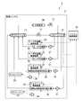
- FIG. 1 is a schematic configuration diagram showing an apparatus configuration of a heat source system according to an embodiment of the present invention.
- the energy supply system 1 includes a heat source system 2 and a system control device 51.
- the heat source system 2 includes a supply header 11, a medium flow rate control valve 12, a return header 13, a turbo chiller side pump 21, a turbo chiller 22, a Genelink side pump 31, and an exhaust heat recovery type absorption cold / hot water.
- the heat source system 2 includes two turbo chiller side pumps 21, two turbo chillers 22, one Genelink side pump 31, and one exhaust heat recovery type absorption chiller / heater 32. And two turbo refrigerator control devices 52 and one Genelink control device 53.
- An exhaust heat recovery type absorption chiller / heater is also referred to as GENELINK.
- the heat source system 2 is connected to the external load 90 by piping.
- a path from the supply header 11 through the external load 90 and the medium flow rate control valve 12 to the return header 13 is configured by piping.
- a path from the return header 13 to the supply header 11 through the turbo chiller side pump 21 and the turbo chiller 22 is configured by piping.
- a path from the return header 13 to the supply header 11 through the Genelink side pump 31 and the exhaust heat recovery type absorption chiller / heater 32 is configured by piping.
- each of the turbo chillers 22 is transferred from the turbo chiller 22 to the turbo chiller 22 via the supply header 11, the external load 90, the medium flow rate adjustment valve 12, the return header 13, and the turbo chiller side pump 21.
- a return path is configured.
- a path from the exhaust heat recovery type absorption chiller / heater 32 to the exhaust heat recovery type absorption chiller / heater 32 through the supply header 11, the external load 90, the medium flow rate control valve 12, the return header 13, and the gene link side pump 31. is configured.
- the heat source system 2 supplies cold heat to the external load 90.
- the external load 90 may be any load as long as it is a supply target of cold heat.
- the external load 90 may be an air conditioning facility provided in a building or a cooling target device provided in a factory.
- Each of the turbo chiller 22 and the exhaust heat recovery type absorption chiller / heater 32 corresponds to an example of a heat source device, and generates cold heat to be supplied to the external load 90.
- the exhaust heat recovery type absorption chiller / heater 32 corresponds to an example of a first heat source unit
- the turbo refrigerator 22 corresponds to an example of a second heat source unit.
- Each of the turbo refrigerator 22 and the exhaust heat recovery type absorption chiller / heater 32 cools a heat transfer medium such as water.
- Each of the turbo chiller 22 and the exhaust heat recovery type absorption chiller / heater 32 is connected to the external load 90 in parallel.
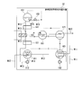
- FIG. 2 is a schematic configuration diagram showing an example of a device configuration when the heat source system 2 includes two exhaust heat recovery type absorption chiller / heaters 32.
- the configuration shown in FIG. 2 is the same as the configuration shown in FIG. 1 except that the heat source system 2 includes two exhaust heat recovery type absorption chiller / heaters 32.
- the heat source system 2 may include a plurality of exhaust heat recovery type absorption chiller / heaters 32.
- the heat source device other than the exhaust heat recovery type absorption chiller / heater included in the heat source system 2 is not necessarily the turbo chiller 22.
- the heat source device other than the exhaust heat recovery type absorption chiller / heater may be a chiller / heater other than the exhaust heat recovery type absorption chiller / heater, or may be a heat source device other than the chiller / heater.
- the heat source system 2 may include one or more exhaust heat recovery type absorption chiller / heaters 32 and one or more turbo chillers 22.
- the heat source system 2 includes at least one absorption chiller / heater of a type that does not collect exhaust heat in addition to one or more exhaust heat recovery type absorption chillers / heaters 32 and one or more turbo chillers 22. You may have.
- the heat source system 2 does not include the turbo chiller 22 and includes at least one absorption chiller / heater of a type that does not recover exhaust heat in addition to the one or more exhaust heat recovery type absorption chillers / heaters 32. Also good.
- one gas engine 33 may be connected to a plurality of exhaust heat recovery type absorption chiller / heaters 32.
- a plurality of gas engines 33 may be connected to one exhaust heat recovery type absorption chiller / heater 32.
- a turbo chiller side pump 21 that pumps the heat transfer medium is provided on the upstream side of each of the turbo chillers 22 as viewed from the flow of the heat transfer medium.
- the turbo chiller side pump 21 sends the heat transfer medium from the return header 13 to the turbo chiller 22.
- a gene link side pump 31 that pumps the heat transfer medium is provided upstream of the exhaust heat recovery type absorption chiller / heater 32 as viewed from the flow of the heat transfer medium.
- the Genelink side pump 31 sends the heat transfer medium from the return header 13 to the exhaust heat recovery type absorption chiller / heater 32.
- Each of the turbo chiller side pump 21 and the Genelink side pump 31 may be a constant flow rate pump or a variable flow rate pump.
- each of the turbo chiller side pump 21 and the Genelink side pump 31 may be variable in flow rate by being variably driven by an inverter motor.
- the heat source system 2 may be configured not to include the medium flow rate control valve 12.
- the supply header 11 accommodates the heat transfer medium cooled by the turbo refrigerator 22 and the exhaust heat recovery type absorption chiller / heater 32.
- the heat transfer medium accommodated in the supply header 11 is sent to the external load 90.
- the heat transfer medium via the external load 90 is sent to the return header 13.
- a medium flow rate adjustment valve 12 is provided between the external load 90 and the return header 13, and the medium flow rate adjustment valve 12 adjusts the flow rate of the heat transfer medium supplied to the external load 90.
- a bypass path is provided between the supply header 11 and the return header 13, and a bypass valve 41 is provided in the bypass path. The bypass valve 41 adjusts the flow rate of the heat transfer medium flowing through the bypass path.
- the system control device 51 corresponds to an example of a number control device, and determines the number of operating turbo chillers 22 and exhaust heat recovery type absorption chiller / heaters 32. Then, the system control device 51 determines the device to be operated and the device to be stopped among the turbo chiller 22 and the exhaust heat recovery type absorption chiller / heater 32 according to the determined number of operating units. Further, the system control device 51 allocates the required amount of cold to the heat source system 2 to the equipment, changes the flow rate of the turbo chiller side pump 21 and the Genelink side pump 31, and sets the turbo chiller control device 52 and the GeneLink control device. This is done by changing the water supply temperature setting at 53.
- the system control device 51 activates the device to the turbo chiller control device 52 and the Genelink control device 53.
- Various instructions are given, such as a stop instruction or an instruction for the amount of cooling demand.
- the turbo chiller control device 52 controls the turbo chiller 22 according to an instruction from the system control device 51.
- the Genelink control device 53 controls the exhaust heat recovery type absorption chiller / heater 32 in accordance with an instruction from the system control device 51.
- FIG. 3 is a schematic block diagram showing a functional configuration of the exhaust heat recovery type absorption chiller / heater 32.
- the exhaust heat recovery type absorption chiller / heater 32 includes an evaporator 101, a refrigerant pump 102, an absorber 111, a solution pump 112, a low temperature heat exchanger 121, and an exhaust heat recovery heat exchange.
- the liquid refrigerant evaporates by taking heat from the heat transfer medium flowing through the path W11.
- water may be used as the refrigerant.
- ammonia may be used as the refrigerant.
- the refrigerant pump 102 is connected to a pipe exiting from the bottom of the evaporator 101. A pipe exiting from the refrigerant pump 102 enters the evaporator 101 at the upper part of the evaporator 101, and a refrigerant spray port is provided in the pipe inside the evaporator 101.
- the refrigerant pump 102 promotes the evaporation of the refrigerant by spraying the liquid refrigerant accumulated at the bottom of the evaporator 101 from the spraying port in the evaporator 101.
- the evaporated refrigerant is referred to as refrigerant vapor.
- the evaporator 101 and the absorber 111 are connected by a pipe, and the refrigerant vapor is sent from the evaporator 101 to the absorber 111.
- the refrigerant that has flowed from the evaporator 101 as the refrigerant vapor is absorbed by the solution.
- the refrigerant is water
- an aqueous lithium bromide solution may be used as the solution.
- the refrigerant is ammonia
- water may be used as the solution.
- coolant with the absorber 111 is called a dilute solution.
- the path W12 is configured, and heat generated in the absorption process by the absorber 111 is removed by the cooling water passing through the path W12.
- a path W13 (a rare solution line) is formed in a pipe from the absorber 111 to the solution pump 112, the low-temperature heat exchanger 121, the exhaust heat recovery heat exchanger 131, and the high-temperature heat exchanger 141 to the high-temperature regenerator 151. It is configured.
- the solution pump 112 sends the rare solution from the absorber 111 to the high temperature regenerator 151 through the path W13.
- the rare solution exchanges heat with the solution flowing from the low temperature regenerator 161 to the absorber 111.
- the rare solution is heated by this heat exchange.
- the exhaust heat recovery heat exchanger 131 the diluted solution is heated by the exhaust heat from the gas engine 33.
- the high temperature heat exchanger 141 the rare solution exchanges heat with the solution flowing from the high temperature regenerator 151 to the low temperature regenerator 161. The rare solution is heated by this heat exchange.
- the exhaust heat recovery type absorption chiller / heater 32 generates cold by receiving at least one of exhaust heat from the gas engine 33 and city gas as fuel. When the exhaust heat is supplied, the exhaust heat recovery type absorption chiller / heater 32 heats the diluted solution in the exhaust heat recovery heat exchanger 131 to generate cold. In addition, when the fuel is supplied, the exhaust heat recovery type absorption chiller / heater 32 heats the rare solution with the high temperature regenerator 151 to generate cold.
- the rare solution is heated by burning the city gas from the path W15 constituted by the gas pipe as the fuel gas, and the refrigerant vapor evaporates from the rare solution.
- the gas flow rate adjustment valve 152 provided in the path W15 adjusts the flow rate of the city gas supplied to the high temperature regenerator 151.
- City gas corresponds to an example of fuel supplied to the exhaust heat recovery type absorption chiller / heater 32.
- the fuel supplied to the exhaust heat recovery type absorption chiller / heater 32 is not limited to city gas but can be various fuels.
- the high temperature regenerator 151 may be supplied with kerosene as fuel, or may be supplied with gas other than city gas such as propane gas.
- the dilute solution is concentrated by evaporation of the refrigerant vapor.
- the solution concentrated in the high temperature regenerator 151 is referred to as an intermediate concentration solution.
- a pipe from the high temperature regenerator 151 to the low temperature regenerator 161 through the high temperature heat exchanger 141 is provided.
- the intermediate concentration solution from the high temperature regenerator 151 exchanges heat with the rare solution in the high temperature heat exchanger 141 and then flows into the low temperature regenerator 161.
- a pipe from the high temperature regenerator 151 to the condenser 171 via the low temperature regenerator 161 is provided, and the refrigerant vapor evaporated from the rare solution in the high temperature regenerator 151 passes through the low temperature regenerator 161 to the condenser. 171 flows in.
- the refrigerant vapor from the high temperature regenerator 151 serves as a heat medium to heat the intermediate concentration solution. This heating evaporates the refrigerant vapor from the intermediate concentration solution.
- the intermediate concentration solution is further concentrated by evaporation of the refrigerant vapor.
- the solution concentrated in the low temperature regenerator 161 is referred to as a high concentration solution.
- a pipe from the low temperature regenerator 161 to the absorber 111 through the low temperature heat exchanger 121 is provided. After the high concentration solution from the low temperature regenerator 161 is heat exchanged with the rare solution in the low temperature heat exchanger 121, It flows into the absorber 111 and absorbs the refrigerant to form a rare solution.
- a pipe connecting the low-temperature regenerator and the condenser 171 is provided.
- the refrigerant vapor evaporated from the intermediate concentration solution in the low temperature regenerator 161 flows into the condenser 171.
- the refrigerant vapor is cooled by the cooling water and condensed to become a liquid refrigerant.
- a pipe connecting the condenser 171 and the evaporator 101 is provided.
- the liquid refrigerant is sent from the condenser 171 to the evaporator 101.
- FIG. 4 is a schematic block diagram showing the functional configuration of the gas engine 33.
- the gas engine 33 includes an intercooler 201, an engine body 202, an exhaust gas hot water boiler 203, an engine cooling water pump 204, a jacket heat exchanger 205, an intercooler pump 211, An intercooler heat exchanger 212, a heat dissipation heat exchanger 213, a first three-way valve 221, and a second three-way valve 222 are provided.
- the intercooler 201 cools the air sucked from the outside of the gas engine 33 and supplies it to the engine body 202.
- the engine body 202 mixes the fuel gas supplied from the outside of the gas engine 33 with the air from the intercooler 201 and burns it.
- the exhaust gas hot water boiler 203 heats the engine coolant with the exhaust gas from the engine body 202.
- the engine cooling water is used for cooling the engine main body 202 and also as a heat medium for transmitting exhaust heat from the engine main body to the jacket heat exchanger 205.
- the exhaust gas hot water boiler 203 may not be attached.
- a pipe is provided from the engine main body 202 to the engine main body 202 via the exhaust gas hot water boiler 203, the engine cooling water pump 204, the jacket heat exchanger 205, the first three-way valve 221 and the second three-way valve 222 to provide engine cooling water.
- the engine coolant is supplied from the engine coolant pump 204 through the circulation path of the engine body 202, the exhaust gas hot water boiler 203, the engine coolant pump 204, the jacket heat exchanger 205, the first three-way valve 221, the second three-way valve 222, the engine. It circulates in the order of the main body 202.
- a pipe connecting the engine coolant pump 204 and the jacket heat exchanger 205 branches to the first three-way valve 221. With this branched pipe, a part of the engine coolant from the engine coolant pump 204 is bypassed to the first three-way valve 221 without passing through the jacket heat exchanger 205.
- the first three-way valve 221 is an electric valve, and adjusts the flow rate of engine coolant that is bypassed from the engine coolant pump 204 to the first three-way valve 221 without passing through the jacket heat exchanger 205.
- the second three-way valve 222 is an electric valve, and adjusts the flow rate of engine coolant from the engine coolant pump 204 to the second three-way valve 222 via the heat dissipation heat exchanger 213.
- the engine cooling water from the exhaust gas hot water boiler 203 and the hot water from the exhaust heat recovery type absorption cold water heater 32 exchange heat.
- the hot water from the exhaust heat recovery type absorption chiller / heater 32 is used as a heat medium for transmitting the exhaust heat of the gas engine 33 to the exhaust heat recovery type absorption chiller / heater 32.
- This hot water is circulated between the jacket heat exchanger 205 and the exhaust heat recovery type absorption chiller / heater 32 by the exhaust heat transfer pump 291.
- the hot water from the exhaust heat recovery type absorption cold water heater 32 is heated by heat exchange in the jacket heat exchanger 205, and the engine cooling water is cooled.
- a pipe is provided from the jacket heat exchanger 205 to the jacket heat exchanger 205 via the exhaust heat recovery type absorption chiller / heater 32, the third three-way valve 294, and the exhaust heat transfer pump 291.
- a heat medium that transmits the exhaust heat of the gas engine 33 to the exhaust heat recovery type absorption chiller / heater 32 circulates between the jacket heat exchanger 205 and the exhaust heat recovery type absorption chiller / heater 32.
- the third three-way valve 294 is an electric valve, and a part of the heat medium from the jacket heat exchanger 205 is bypassed to the third three-way valve 294 without passing through the exhaust heat recovery type absorption chiller / heater 32. Adjust.
- the intercooler pump 211 is provided in a pipe that returns from the intercooler 201 to the intercooler 201 via the intercooler heat exchanger 212.
- the cooling water having absorbed heat from the air by the intercooler pump 211 is sent to the intercooler heat exchanger 212 and cooled, and then returns to the intercooler 201.
- the cooling water used for the intercooler 201 exchanges heat with the cooling water from the cooling tower. By this heat exchange, the cooling water used for the intercooler 201 is cooled as described above.
- a pipe is provided from the heat radiation heat exchanger 213 to the heat radiation heat exchanger 213 via the cooling tower 292, the cooling tower side pump 293, and the intercooler heat exchanger 212.
- the cooling water flowing from the cooling tower 292 through the intercooler heat exchanger 212 into the heat dissipation heat exchanger 213 further exchanges heat with the engine cooling water.
- the engine coolant is cooled as described above.
- the cooling tower 292 the cooling water heated by heat exchange in the intercooler heat exchanger 212 and the heat radiation heat exchanger 213 performs heat radiation.
- the cooling water radiated by the cooling tower returns to the cooling tower 292 via the intercooler heat exchanger 212 and the heat radiating heat exchanger 213 by the cooling tower side pump 293.
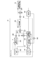
- FIG. 5 is a schematic block diagram showing a functional configuration of the system control device 51.
- the system control device 51 includes a communication unit 310, a storage unit 380, and a control unit 390.
- the control unit 390 includes a waste heat utilization maximum load acquisition unit (acquisition unit) 391, an optimum load range determination unit (determination unit) 392, and a number control unit 393.
- the system control device 51 is realized using, for example, a computer.
- the communication unit 310 communicates with the turbo chiller control device 52.
- the system control device 51 acquires state information of the turbo chiller 22 through communication with the turbo chiller control device 52 and instructs the turbo chiller control device 52 to control the turbo chiller 22. Further, the communication unit 310 communicates with the gene link control device 53.
- the system control device 51 acquires state information of the exhaust heat recovery type absorption chiller / heater 32 through communication with the Genelink control device 53, and controls the exhaust heat recovery type absorption chiller / heater 32. To instruct.
- the state information of the chiller is acquired by sensor installation or hardware connection.
- the storage unit 380 is configured using a storage device included in the system control apparatus 51 and stores various types of information.
- the control unit 390 controls each unit of the system control device 51 to perform various processes.
- the exhaust heat utilization maximum load acquisition unit 391 obtains the exhaust heat utilization maximum load, which is the maximum load (maximum capacity) when the exhaust heat recovery type absorption chiller / heater 32 receives supply of only exhaust heat, as the exhaust heat recovery type absorption cold / cold temperature. It calculates
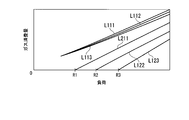
- FIG. 6 is a graph showing an example of the relationship between the load of the exhaust heat recovery type absorption chiller / heater 32 and the amount of gas consumption when there is sufficient exhaust heat from the gas engine 33.
- the horizontal axis of FIG. 6 shows the load of the exhaust heat recovery type absorption chiller / heater 32, and the vertical axis shows the gas consumption.
- the load here is the amount of heat that the heat source unit outputs cold.
- Lines L111 to L113 indicate the relationship between the load and the gas consumption amount when no exhaust heat is supplied from the gas engine 33.
- Lines L111, L112, and L113 indicate the relationship between the load and the gas consumption when the cooling water inlet temperature is T1 ° C., T2 ° C., and T3 ° C., respectively.
- the cooling water inlet temperature here is the temperature of the cooling water at the inlet to the absorber 111.
- T1, T2, and T3 are all constants and satisfy “T1>T2> T3”.
- Lines L121 to L123 all show the relationship between the load and the amount of gas consumed when exhaust heat is supplied from the gas engine 33.
- Lines L121, L122, and L123 indicate the relationship between the load and the gas consumption when the cooling water inlet temperature is T1 ° C., T2 ° C., and T3 ° C., respectively.
- the gas consumption may be zero (0) below a certain load. it can.
- the cooling water inlet temperature is T1 ° C.
- the gas consumption is zero at the load R1 or lower.
- a relationship between the load and the gas consumption when the cooling water inlet temperature is T1 ° C. is indicated by a line L121.
- R1 is a constant.
- the cooling water inlet temperature is T2 ° C.
- the gas consumption is zero when the load is R2 or less.
- the relationship between the load and the gas consumption when the cooling water inlet temperature is T2 ° C. is indicated by a line L122.
- R2 is a constant.
- the gas consumption is zero at the load R3 or lower.
- the relationship between the load and the gas consumption when the cooling water inlet temperature is T3 ° C. is indicated by a line L123.
- R3 is a constant.
- the maximum load among the loads where the gas consumption of the exhaust heat recovery type absorption chiller / heater 32 becomes zero is referred to as exhaust heat utilization maximum load.
- the maximum exhaust heat utilization load when the cooling water inlet temperature is T1 ° C. is the load R1.
- the maximum exhaust heat utilization load when the cooling water inlet temperature is T2 ° C. is the load R2.
- the maximum exhaust heat utilization load when the cooling water inlet temperature is T3 ° C. is the load R3.
- the system controller 51 controls the number of operating turbo chillers 22 and the exhaust heat recovery type absorption chiller / heater 32 to operate the exhaust heat recovery type absorption chiller / heater 32 near the maximum exhaust heat utilization load, Gas consumption of the exhaust heat recovery type absorption chiller / heater 32 can be reduced. It is considered that the COP (Coefficient Of Performance) of the exhaust heat recovery type absorption chiller / heater 32 is maximized at the maximum exhaust heat utilization load.
- the relationship between the maximum exhaust heat utilization load Q opt1 and the cooling water inlet temperature Ti as shown in FIG. 6 is expressed by the function f 1 of the cooling water inlet temperature Ti as shown in the equation (1).
- the storage unit 380 stores the function f 1 in advance, and the exhaust heat utilization maximum load acquisition unit 391 reads the function f 1 from the storage unit 380. Further, the exhaust heat utilization maximum load acquisition unit 391 acquires the measured value of the cooling water inlet temperature from the exhaust heat recovery type absorption chiller / heater 32 via the communication unit 310. Then, the exhaust heat utilization maximum load acquisition unit 391 calculates the exhaust heat utilization maximum load Q opt1 by substituting the obtained cooling water inlet temperature measurement value into the function f 1 .
- the format of the information indicating the relationship between the coolant inlet temperature and the maximum exhaust heat utilization load stored in the storage unit 380 is not limited to the function format.
- the storage unit 380 may store the relationship between the cooling water inlet temperature and the exhaust heat utilization maximum load in a table format.
- the cooling water temperature used for the exhaust heat utilization maximum load acquisition part 391 to acquire the exhaust heat utilization maximum load is not limited to the cooling water inlet temperature.
- the exhaust heat utilization maximum load acquisition unit 391 may use the temperature of the cooling water at the outlet of the absorber 111.
- the exhaust heat utilization maximum load Q opt1 and the cooling water inlet temperature Ti are in a substantially linear relationship
- a linear function of the cooling water inlet temperature Ti is used as the function f 1 and the exhaust heat utilization maximum load Q opt1 and the cooling water inlet
- the relationship with the temperature Ti can be linearly approximated.
- the storage unit 380 only needs to store a linear function as the function f 1 , so that a small storage capacity is required.
- the exhaust heat utilization maximum load acquisition unit 391 can calculate the exhaust heat utilization maximum load by a simple process of calculating by assigning a value to a linear function.
- the processing load is light.
- FIG. 6 shows an example of the relationship between the load of the exhaust heat recovery type absorption chiller / heater 32 and the gas consumption when there is sufficient exhaust heat from the gas engine 33.
- the exhaust heat recovery type absorption chiller / heater 32 has sufficient exhaust heat. The case where it is not possible to obtain is considered. Therefore, the relationship between the optimum load range of the exhaust heat recovery type absorption chiller / heater 32, the exhaust heat recovery amount E from the gas engine 33, and the cooling water inlet temperature Ti will be described below.
- FIG. 7 is a graph showing an example of the relationship between the load of the exhaust heat recovery type absorption chiller / heater 32 and the amount of exhaust heat recovered from the gas engine 33.
- the horizontal axis of FIG. 7 shows the load of the exhaust heat recovery type absorption chiller / heater 32, and the vertical axis shows the amount of exhaust heat recovery.
- the amount of exhaust heat recovered here is the amount of exhaust heat recovered from the gas engine 33.
- Line L21 shows the relationship between the load and the amount of exhaust heat recovery when the cooling water inlet temperature is T1 ° C.
- the left end (point P21) of the line L21 shows the relationship between the load at the maximum exhaust heat utilization load and the amount of exhaust heat recovery. In the case of the maximum exhaust heat utilization load, the gas consumption is zero.
- the line L21 shows the relationship between the load and the exhaust heat recovery amount when the gas consumption is increased toward the right.
- Line L22 shows the relationship between the load and the amount of exhaust heat recovery when the cooling water inlet temperature is T2 ° C.
- the left end (point P22) of the line L22 shows the relationship between the load at the maximum exhaust heat utilization load and the exhaust heat recovery amount.
- the line L22 shows the relationship between the load and the exhaust heat recovery amount when the gas consumption is increased toward the right.
- a line L23 indicates the relationship between the load and the amount of exhaust heat recovery when the cooling water inlet temperature is T3 ° C.
- the left end (point P23) of the line L23 shows the relationship between the load at the maximum exhaust heat utilization load and the exhaust heat recovery amount.
- the relationship between the load and the exhaust heat recovery amount when the gas consumption is increased as it goes to the right of the line L23 is shown.
- the relationship between the load at the maximum exhaust heat utilization load and the amount of exhaust heat recovery is shown as a line L24. It can be considered that this line L24 indicates the exhaust heat recovery amount necessary for reducing the gas consumption amount to zero for each load.
- the relationship between the exhaust heat utilization maximum load Q opt2 and the exhaust heat recovery amount E as shown by the line L24 is expressed by the function f 2 of the exhaust heat recovery amount E as shown in Expression (2).
- the relationship between the waste heat utilization maximum load Q opt2 and the exhaust heat recovery amount E can be linearly approximated.
- the exhaust heat recovery amount E is obtained from the output of the gas engine 33, for example.
- the exhaust heat from the gas engine 33 is calculated by the number of operating exhaust heat recovery type absorption chiller / heaters 32.
- the divided exhaust heat per vehicle is used as the exhaust heat recovery amount E.
- the load of the exhaust heat recovery type absorption chiller / heater 32 is set to be less than the smaller one of Q opt1 and Q opt2. There is a need. Therefore, the exhaust heat utilization maximum load Q opt of the exhaust heat recovery type absorption chiller / heater 32 is expressed as in Expression (3).
- the function MIN outputs the minimum value among the values of the plurality of arguments. Therefore, MIN (f 1 (Ti), f 2 (E)) indicates the smaller value of the values of f 1 (Ti) and f 2 (E).
- the storage unit 380 stores the function of the function formula (3) in advance, and the exhaust heat utilization maximum load acquisition unit 391 reads the function of the formula (3) from the storage unit 380. Further, the exhaust heat utilization maximum load acquisition unit 391 acquires the measured value of the cooling water inlet temperature from the Genelink control device 53 via the communication unit 310. Further, the exhaust heat utilization maximum load acquisition unit 391 acquires the exhaust heat amount of the gas engine 33.
- the exhaust heat utilization maximum load acquisition unit 391 acquires the gas engine output from the control device of the gas engine 33 via the communication unit 310 and calculates the amount of exhaust heat based on the obtained gas engine output. Then, the exhaust heat utilization maximum load acquisition unit 391 calculates the exhaust heat utilization maximum load Q opt1 by substituting the obtained cooling water inlet temperature measurement value into the function f 1 .
- the storage unit 380 may store the relationship between the amount of exhaust heat supplied to the exhaust heat recovery type absorption chiller / heater 32 and the maximum exhaust heat utilization load in a table format.
- the optimal load range determination unit 392 determines a predetermined load range based on the maximum exhaust heat utilization load obtained by the exhaust heat utilization maximum load acquisition unit 391 as the optimal load range of the exhaust heat recovery type absorption chiller / heater 32.
- the optimum load range determined by the optimum load range determination unit 392 will be described with reference to FIGS.
- FIG. 8 is a graph showing an example of setting the optimum load range of the exhaust heat recovery type absorption chiller / heater 32.
- the horizontal axis in FIG. 8 indicates the load, and the vertical axis indicates the cooling water inlet temperature.
- the optimum load range of the exhaust heat recovery type absorption chiller / heater 32 corresponds to an example of the first optimum load range.
- FIG. 8 shows an example of setting the optimum load range when there is sufficient exhaust heat from the gas engine 33, and the optimum load range determining unit 392 determines a predetermined amount from the maximum exhaust heat utilization load obtained by Equation (1).
- the area within the range is set to the optimum load range.
- the line L31 shows an example of the exhaust heat utilization maximum load Q opt1 obtained by the equation (1).
- the optimum load range determining unit 392 sets an area A11 within ⁇ 15% from the exhaust heat utilization maximum load Q opt1 as the optimum load range. Similarly, when the exhaust heat from the gas engine 33 is not sufficient, the region within the predetermined load range from the maximum exhaust heat utilization load obtained by the equation (3) can be set as the optimum load range. As described above, the optimum load range determination unit 392 determines the predetermined load range based on the exhaust heat utilization maximum load as the optimum load range of the exhaust heat recovery type absorption chiller / heater 32.
- FIG. 9 is a graph showing an example of setting the optimum load range of the turbo chiller 22.
- the horizontal axis in FIG. 9 indicates the load of the turbo refrigerator 22, and the vertical axis indicates the coefficient of performance of the turbo refrigerator 22.
- a known method can be used as a method of obtaining the coefficient of performance of the turbo refrigerator.
- the optimum load range of the turbo refrigerator 22 corresponds to an example of the second optimum load range.
- Lines L411 to L416 indicate the relationship between the load of the centrifugal chiller 22 and the coefficient of performance for each cooling water temperature.
- the line L421 connects the points with the highest coefficient of performance of each of the lines L411 to L416.
- the optimum load range determination unit 392 sets an area within a predetermined range from the load at which the coefficient of performance is maximum as indicated by a line L421 as the optimum load range of the turbo chiller 22.
- the optimum load range determination unit 392 sets the optimum load range of the turbo chiller 22 within the range from the maximum value of the coefficient of performance to “maximum value ⁇ 0.1”. An optimal load range may be set. Alternatively, the optimum load range determination unit 392 sets the optimum load range of the turbo chiller 22 based on the load, such as setting the range of ⁇ 10 loads from the load at which the coefficient of performance is maximized to the optimum load range of the turbo chiller 22. A range may be set.
- the number control unit 393 controls the number of operating turbo chillers 22 and the exhaust heat recovery type absorption chiller / heater 32 based on the optimum load range obtained by the optimum load range determination unit. Specifically, the number control unit 393 calculates the number of operating units that can operate the turbo chiller 22 and the exhaust heat recovery type absorption chiller / heater 32 within the optimum load range acquired by the optimum load range determination unit 392. .
- the number control unit 393 is set to the required load on the heat source system 2, the sum of the minimum value of the optimum load range of the exhaust heat recovery type absorption chiller / heater 32 to be operated, and the turbo chiller 22 to be operated. Compare the sum of the minimum values in the optimum load range. The minimum value of the range is the lower limit value in the range. When the required load is smaller than the sum of the minimum values of the optimum load range, the number control unit 393 decreases the number of operating exhaust heat recovery type absorption chiller / heater 32 or turbo chiller 22 by one.
- the number control unit 393 sets the required load on the heat source system 2 to the sum of the minimum values of the optimum load range of the exhaust heat recovery type absorption chiller / heater 32 to be operated and the turbo chiller 22 to be operated.
- the sum should be greater than or equal to the sum of the minimum values of the optimum load range.
- the number control unit 393 is set to the required load on the heat source system 2, the sum of the maximum value of the optimum load range of the exhaust heat recovery type absorption chiller / heater 32 to be operated, and the turbo chiller 22 to be operated. Compare the sum of the maximum values of the optimum load range. The maximum value of the range is the upper limit value in the range. When the required load is greater than the sum of the maximum values in the optimum load range, the number control unit 393 increases the number of operating exhaust heat recovery type absorption chiller / heaters 32 or turbo chillers 22 by one.
- the number control unit 393 sets the required load on the heat source system 2 to the sum of the maximum value of the optimum load range of the exhaust heat recovery type absorption chiller / heater 32 to be operated and the turbo chiller 22 to be operated. Make it less than the sum of the maximum value of the optimum load range.
- the number control unit 393 determines the turbo chiller 22 or the exhaust heat recovery type absorption chiller / heater 32 to be started or stopped based on the calculated operation number.
- Various methods can be used as a method by which the number control unit 393 determines a heat source machine to be started or stopped.
- the heat source machine that the number control unit 393 starts or stops is the turbo chiller 22 or the exhaust heat recovery type absorption chiller / heater 32.
- the number control unit 393 may preferentially start the heat source machine with a short operation time and preferentially stop the heat source machine with a long operation time.
- priorities may be assigned in advance to each of the heat source devices, and the number control unit 393 may determine a heat source device to be activated or stopped according to the priority order.
- the number control unit 393 determines load distribution for the turbo refrigerator 22 and the exhaust heat recovery type absorption chiller / heater 32 to be operated. At that time, the number control unit assigns loads so that both of the turbo chiller 22 to be operated and the exhaust heat recovery type absorption chiller / heater 32 have loads within the optimum load range.
- FIG. 10 is a flowchart showing a processing procedure in which the system controller 51 determines the number of operating units of the turbo chiller 22 and the exhaust heat recovery type absorption chiller / heater 32.
- the number control unit 393 acquires water supply data such as the main pipe flow rate F of the cooling water sent to the external load 90, the cold water injection temperature T s , and the cold water return temperature Tr (step S ⁇ b> 111). Further, the number control unit 393 acquires the ratio Cp and specific heat ⁇ of the cooling water sent to the external load 90 (Step S112). These values are stored in advance by the storage unit 380 as constants, for example.
- the number control part 393 calculates the heat load (specifically, the amount of cooling energy consumed by the external load 90) Q of the entire heat source system 2 based on the equation (4) (step S113).
- the heat load Q corresponds to an example of a required load for the heat source system 2.
- the method by which the number control unit 393 acquires the required load is not limited to this.
- the number control unit 393 may acquire information indicating the required load from the control device for the external load 90 via the communication unit 310.
- the optimal load range determination part 392 acquires the optimal load range of the turbo refrigerator 22 (step S121).
- the optimum load range determination unit 392 acquires the optimum load range based on the relationship between the load of the centrifugal chiller 22 and the coefficient of performance.
- the maximum value of the optimum load range is expressed as Q opt_max and the minimum value is expressed as Q opt_min .
- the optimum load range is acquired for each turbo refrigerator 22.
- the exhaust heat utilization maximum load acquisition unit 391 reads the functions f 1 (Ti) and f 2 (E) stored in advance in the storage unit 380 (step S131). Further, the exhaust heat utilization maximum load acquisition unit 391 acquires a measured value of the cooling water inlet temperature Ti and a calculated value of the exhaust heat recovery amount E (step S132). And the exhaust heat utilization maximum load acquisition part 391 calculates
- the optimal load range determination part 392 calculates
- the number control unit 393 determines whether or not the heat load Q of the heat source system 2 as a whole is larger than the sum of the maximum value Q opt_max in the optimum negative range of the turbo chiller 22 and the exhaust heat recovery type absorption chiller / heater 32. Is determined (step S141). When it is determined that the heat load of the entire heat source system 2 is larger than the sum of the maximum values of the optimum load ranges of the turbo chiller 22 and the exhaust heat recovery type absorption chiller / heater 32 (step S141: YES), the number control unit 393 Then, an increase in the number of heat source systems 2 or turbo chillers 22 is determined (step S151). Specifically, the number control unit 393 determines to start any one of the stopped turbo chiller 22 or the exhaust heat recovery type absorption chiller / heater 32. After step S151, the process of FIG.
- step S141 when it is determined in step S141 that the heat load of the entire heat source system 2 is equal to or less than the sum of the maximum values of the optimum load ranges of the turbo chiller 22 and the exhaust heat recovery type absorption chiller / heater 32 (step S141: NO)
- the number controller 393 determines whether the heat load Q of the entire heat source system 2 is smaller than the sum of the minimum value Q opt_min in the optimum negative range of the turbo chiller 22 and the exhaust heat recovery type absorption chiller / heater 32. (Step S161).
- step S161 The case where it is determined that the heat load of the entire heat source system 2 is smaller than the sum of the minimum values of the optimum load ranges of the turbo chiller 22 and the exhaust heat recovery type absorption chiller / heater 32 (step S161: YES) will be described.
- the number control unit 393 determines whether or not the number of operating heat source devices (the turbo chiller 22 and the exhaust heat recovery type absorption chiller / heater 32) is two or more (step S162). When it is determined that the number of operating units is two or more (step S162: YES), the number control unit 393 determines a decrease in the number of turbo chillers 22 or the exhaust heat recovery type absorption chiller / heater 32 (step S171).
- the number control unit 393 determines to stop any one of the operating turbo chiller 22 or the exhaust heat recovery type absorption chiller / heater 32.
- the number control unit 393 determines the refrigerator to be stopped so that at least one exhaust heat recovery type absorption chiller / heater 32 is operated. This is because the exhaust heat recovery type absorption chiller / heater 32 recovers exhaust heat and generates cold heat, thereby increasing the efficiency of the heat source system 2.
- step S171 the process of FIG.
- step S161 step S161: NO
- the process of FIG. In this case, the number of turbo chillers 22 or exhaust heat recovery type absorption chiller / heaters 32 is not increased or decreased.
- step S162 If it is determined in step S162 that the number of operating units is one or less (step 162: NO), the process in FIG. 10 is terminated. In this case, the number of turbo chillers 22 or exhaust heat recovery type absorption chiller / heaters 32 is not increased or decreased. This is because cold heat cannot be supplied if the number of operating heat source machines becomes zero. As described above, the number control unit 393 operates at least one exhaust heat recovery type absorption chiller / heater 32, and the maximum value of the optimum load range of the exhaust heat recovery type absorption chiller / heater 32 is the heat source system. When the load is less than the required load for 2, the number of heat source units is controlled.
- the number control unit 393 has one exhaust heat recovery type absorption chiller / heater 32. Maintain driving.
- the optimum load range determination unit 392 sets the exhaust heat recovery type absorption chiller / heater 32 to a certain extent, and widens the optimum load range set in the turbo refrigerator 22 to some extent.
- the sum of the minimum values of the optimum load range of the heat source equipment to be operated is not less than the required load, and the sum of the maximum values of the optimum load range of the heat source equipment to be operated is required.
- the number control unit 393 may control only the number of operating turbo chillers 22.
- the exhaust heat recovery type absorption chiller / heater 32 is always operated, and the number control unit 393 controls the operation number of only the turbo chiller 22 so that the exhaust heat recovery type absorption chiller / heater 32 is preferentially operated. You may make it make it.
- the number control unit 393 may control the number of operating turbo chillers 22 and the exhaust heat recovery type absorption chiller / heater 32.
- the exhaust heat utilization maximum load acquisition unit 391 includes the exhaust heat utilization maximum load of the exhaust heat recovery type absorption chiller / heater 32, information indicating the relationship between the cooling water temperature and the exhaust heat utilization maximum load, and Determined based on cooling water temperature.
- the optimal load range determination part 392 calculates
- the number control unit 393 is based on the optimum load range determined by the optimum load range determination unit 392 when the required load on the heat source system 2 is larger than the maximum value of the optimum load range of the exhaust heat recovery type absorption chiller / heater 32. Then, the number of operating turbo chillers 22 is controlled. Specifically, the number control unit 393 adds the minimum value of the first optimum load range of the exhaust heat recovery type absorption chiller / heater 32 to be operated and the minimum value of the second optimum load range of the turbo chiller 22 to be operated. And the sum of the sum of the maximum values of the first optimum load range and the sum of the maximum values of the second optimum load range is a request for the heat source system 2.
- the number of operating turbo chillers 22 is controlled so as to exceed the load.
- the first optimum load range is the optimum load range of the exhaust heat recovery type absorption chiller / heater 32 obtained by the optimum load range determination unit 392.
- the second optimum load range is an optimum load range that is set for the turbo refrigerator 22 and in which the turbo refrigerator 22 generates cold.
- the number control unit 393 controls the number of operating turbo chillers 22 and the exhaust heat recovery type absorption chiller / heater 32 according to the cooling water temperature, so that the heat source system 2 can be operated efficiently.
- the heat source system 2 includes one exhaust heat recovery type absorption chiller / heater 32 as in the configuration shown in FIG. 1, the exhaust heat recovery type absorption chiller / heater receives the supply of gas fuel and cools it.
- the heat source system 2 can be operated efficiently when it is less costly for the turbo refrigerator 22 to generate cold heat than to generate it.
- the number control unit 393 maintains the operation of at least one exhaust heat recovery type absorption chiller / heater 32, and is the sum of the sum of the minimum values of the first optimum load range and the sum of the minimum values of the second optimum load range. So that the sum of the sum of the maximum values of the first optimum load range and the sum of the maximum values of the second optimum load range is equal to or greater than the demand load of the heat source system 2.
- the number of operating units of the exhaust heat recovery type absorption chiller / heater 32 other than the exhaust heat recovery type absorption chiller / heater 32 that maintains the operation is controlled. You may do it. Thereby, when the heat source system 2 includes a plurality of exhaust heat recovery type absorption chiller / heaters 32, the heat source system 2 can be operated efficiently.
- the exhaust heat utilization maximum load acquisition unit 391 is further supplied to the information indicating the relationship between the amount of exhaust heat supplied to the exhaust heat recovery type absorption chiller / heater 32 and the optimum load, and the exhaust heat recovery type absorption chiller / heater.
- the optimum load may be obtained based on the amount of exhaust heat. Accordingly, the number control unit 393 can control the number of operating turbo chillers 22 and the exhaust heat recovery type absorption chiller / heater 32 according to the exhaust heat amount exhaust heat amount from the gas engine 33, and the exhaust heat amount is not sufficient. Even in this case, the heat source system 2 can be operated efficiently.
- the energy supply system 1 attempts to minimize the energy consumption of the heat source machine has been described above as an example, but the energy supply system 1 may be configured to minimize the gas charge and the electricity charge.
- the optimum load range determination unit 392 determines the optimum load range of each heat source unit based on the gas rate and the electricity rate.
- the energy supply system 1 may minimize the gas charge and the electricity charge. For example, when the gas charge is low, the load of the exhaust heat recovery type absorption chiller / heater 32 is increased, for example, the optimum load range determination unit 392 multiplies the load of the exhaust heat recovery type absorption chiller / heater 32 by 1.1. You may do it.
- the energy supply system 1 may minimize the amount of carbon dioxide emission. In this case, the optimal load range determination unit 392 determines the optimal load range of each heat source unit based on the carbon dioxide emission amount.
- the optimum load range determination unit 392 may multiply the load of the inverter turbo chiller by 0.9 to allow an early stage increase.
- the system controller 51 matches the optimum load range of the exhaust heat recovery type absorption chiller / heater 32.
- the cold water flow rate may be set. Thereby, the system control apparatus 51 can perform control of the heat source system 2 more finely.
- a program for realizing all or part of the functions of the system control device 51 is recorded on a computer-readable recording medium, and the program recorded on the recording medium is read into the computer system and executed. You may perform the process of each part.
- the “computer system” here includes an OS and hardware such as peripheral devices.
- “Computer-readable recording medium” refers to a portable medium such as a flexible disk, a magneto-optical disk, a ROM, and a CD-ROM, and a storage device such as a hard disk built in a computer system.
- the program may be a program for realizing a part of the functions described above, and may be a program capable of realizing the functions described above in combination with a program already recorded in a computer system.
- Embodiments of the present invention are a heat source other than a first heat source machine and an exhaust heat recovery type absorption chiller / heater that is an exhaust heat recovery type absorption chiller / heater that generates cold by receiving at least one of exhaust heat and fuel.
- the first heat source machine uses the exhaust heat utilization maximum load, which is the maximum load when the first heat source machine is supplied with only the exhaust heat and generates cold.
- An optimum load range determining unit that determines a load range as an optimum load range of the first heat source unit, and operating at least one of the first heat source units, and a required load on the heat source system is an optimum of the first heat source unit. Greater than maximum load range, the sum of the minimum values of the first optimum load range, which is the optimum load range of the first heat source machine to be operated among the first heat source machines, and the second heat source machine to be operated among the second heat source machines are cold.
- a number control unit that controls the number of operating second heat source units so that the sum of the maximum values of the second optimum load ranges is equal to or greater than a required load on the heat source system.
- the heat source system can be operated efficiently.
Landscapes
- Engineering & Computer Science (AREA)
- Mechanical Engineering (AREA)
- General Engineering & Computer Science (AREA)
- Physics & Mathematics (AREA)
- Thermal Sciences (AREA)
- Combustion & Propulsion (AREA)
- Chemical & Material Sciences (AREA)
- Life Sciences & Earth Sciences (AREA)
- Sustainable Development (AREA)
- Sustainable Energy (AREA)
- Air Conditioning Control Device (AREA)
- Compression-Type Refrigeration Machines With Reversible Cycles (AREA)
- Sorption Type Refrigeration Machines (AREA)
Abstract
排熱回収型吸収冷温水器である第1熱源機と、排熱回収型吸収冷温水器以外の第2熱源機とを備える熱源システムにおける熱源機の運転台数を制御する台数制御装置が、第1熱源機が排熱のみの供給を受ける場合の最大負荷である排熱利用最大負荷を求める取得部と、排熱利用最大負荷を基準とする所定負荷範囲を第1熱源機の最適負荷範囲である第1最適負荷範囲と決定する決定部と、運転させる第1熱源機の最適負荷範囲の最小値の合計と、運転させる第2熱源機の最適負荷範囲である第2最適負荷範囲の最小値の合計との和が、熱源システムへの要求負荷以下、かつ、第1最適負荷範囲の最大値の合計と第2最適負荷範囲の最大値の合計との和が、熱源システムへの要求負荷以上になるように第2熱源機の運転台数を制御する台数制御部と、を備える。
Description
本発明は、台数制御装置、エネルギー供給システム、台数制御方法及びプログラムに関する。
本願は、2015年5月13日に、日本国に出願された特願2015-097881号に基づき優先権を主張し、その内容をここに援用する。
本願は、2015年5月13日に、日本国に出願された特願2015-097881号に基づき優先権を主張し、その内容をここに援用する。
熱源システムの1つに排熱回収型吸収冷温水器を備える熱源システムがある。排熱回収型吸収冷温水器は、ガスエンジン等からの排熱を回収する。排熱回収型吸収冷温水器が排熱を回収することで、排熱回収型吸収冷温水器への燃料ガスの供給量を低減することができる。
排熱回収型吸収冷温水器を備える熱源システムに関連する技術が特許文献1に記載されている。特許文献1に記載のガス吸収冷温水器が排熱回収型吸収冷温水器に相当し、冷温水システムが熱源システムに相当する。この冷温水システムは、燃料ガスのコストと補機の運転コストとの比較によりガス吸収冷温水器の運転台数を切り替える。具体的には、特許文献1に記載の冷温水システムは、1台のガス吸収冷温水器の運転を排熱回収と燃料ガスの両方により行った場合の燃料ガスのコストが、2台目のガス吸収冷温水器の運転を排熱回収により行った場合の補機の運転コストを上回る負荷率にて2台目のガス吸収冷温水器の運転を開始する。
排熱回収型吸収冷温水器を備える熱源システムに関連する技術が特許文献1に記載されている。特許文献1に記載のガス吸収冷温水器が排熱回収型吸収冷温水器に相当し、冷温水システムが熱源システムに相当する。この冷温水システムは、燃料ガスのコストと補機の運転コストとの比較によりガス吸収冷温水器の運転台数を切り替える。具体的には、特許文献1に記載の冷温水システムは、1台のガス吸収冷温水器の運転を排熱回収と燃料ガスの両方により行った場合の燃料ガスのコストが、2台目のガス吸収冷温水器の運転を排熱回収により行った場合の補機の運転コストを上回る負荷率にて2台目のガス吸収冷温水器の運転を開始する。
特許文献1では、排熱回収により賄われる負荷率がガスエンジン発電機の運転負荷率によって変わることが記載されている。しかしながら、特許文献1には、排熱回収により賄われる負荷率以外の要因への対応方法は示されていない。排熱回収により賄われる負荷率以外の要因によって排熱回収型吸収冷温水器の能力が変化する場合にも、熱源システムを効率よく運転させられることが望まれる。
本発明は、熱源システムを効率よく運転させることができる台数制御装置、エネルギー供給システム、台数制御方法及びプログラムを提供する。
本発明の第1の態様によれば、台数制御装置は、排熱及び燃料のうち少なくとも一方の供給を受けて冷熱を生成する排熱回収型吸収冷温水器である少なくとも1台の第1熱源機と、排熱回収型吸収冷温水器以外の熱源機である第2熱源機とを備える熱源システムにおける前記第1熱源機が、前記排熱のみの供給を受けて冷熱を生成する場合の最大負荷である排熱利用最大負荷を、前記第1熱源機の冷却水温度と前記排熱利用最大負荷との関係を示す情報、及び、現在の冷却水温度に基づいて求める取得部と、前記排熱利用最大負荷を基準とする所定負荷範囲を、前記第1熱源機の最適負荷範囲である第1最適負荷範囲と決定する決定部と、前記少なくとも1台の第1熱源機を運転させると共に、前記熱源システムに対する要求負荷が前記第1熱源機の最適負荷範囲の最大値より大きい場合に、運転させる第1熱源機の前記第1最適負荷範囲の最小値の合計と、運転させる第2熱源機が冷熱を生成する最適負荷範囲として設定されている第2最適負荷範囲の最小値の合計との和が、前記熱源システムに対する要求負荷以下になり、かつ、前記第1最適負荷範囲の最大値の合計と前記第2最適負荷範囲の最大値の合計との和が、前記熱源システムに対する要求負荷以上になるように、前記第2熱源機の運転台数を制御する台数制御部と、を備える。
前記少なくとも1台の第1熱源機は、複数の第1熱源機であり、前記台数制御部は、前記複数の第1熱源機のうち少なくとも1台の運転を維持すると共に、前記第1最適負荷範囲の最小値の合計と前記第2最適負荷範囲の最小値の合計との和が前記熱源システムに対する要求負荷以下になり、かつ、前記第1最適負荷範囲の最大値の合計と前記第2最適負荷範囲の最大値の合計との和が前記熱源システムに対する要求負荷以上になるように、前記複数の第1熱源機のうち運転を維持する前記少なくとも1台の第1熱源機以外の第1熱源機、及び、前記第2熱源機の運転台数のうち、少なくともいずれかの運転台数を制御する、ようにしてもよい。
前記取得部は、さらに、前記第1熱源機に供給される排熱量と前記排熱利用最大負荷との関係を示す情報、及び、第1熱源機に供給される現在の排熱量に基づいて、前記排熱利用最大負荷を求める、ようにしてもよい。
本発明の第2の態様によれば、エネルギー供給システムは、上述した台数制御装置と、前記熱源システムと、を備える。
本発明の第3の態様によれば、台数制御方法は、排熱及び燃料のうち少なくとも一方の供給を受けて冷熱を生成する排熱回収型吸収冷温水器である少なくとも1台の第1熱源機と、排熱回収型吸収冷温水器以外の熱源機である第2熱源機とを備える熱源システムにおける前記第1熱源機および前記第2熱源機の運転台数を制御する台数制御装置のための台数制御方法であって、前記第1熱源機が前記排熱のみの供給を受けて冷熱を生成する場合の最大負荷である排熱利用最大負荷を、前記第1熱源機の冷却水温度と前記排熱利用最大負荷との関係を示す情報、及び、現在の冷却水温度に基づいて求め、前記排熱利用最大負荷を基準とする所定負荷範囲を、前記第1熱源機の最適負荷範囲である第1最適負荷範囲と決定し、前記少なくとも1台の第1熱源機を運転させると共に、前記熱源システムに対する要求負荷が前記第1熱源機の最適負荷範囲の最大値より大きい場合に、運転させる第1熱源機の前記第1最適負荷範囲の最小値の合計と、運転させる第2熱源機が冷熱を生成する最適負荷範囲として設定されている第2最適負荷範囲の最小値の合計との和が、前記熱源システムに対する要求負荷以下になり、かつ、前記第1最適負荷範囲の最大値の合計と前記第2最適負荷範囲の最大値の合計との和が、前記熱源システムに対する要求負荷以上になるように、前記第2熱源機の運転台数を制御することを含む。
本発明の第4の態様によれば、プログラムは、排熱及び燃料のうち少なくとも一方の供給を受けて冷熱を生成する排熱回収型吸収冷温水器である少なくとも1台の第1熱源機と、排熱回収型吸収冷温水器以外の熱源機である第2熱源機とを備える熱源システムを制御するコンピュータに、前記第1熱源機が前記排熱のみの供給を受けて冷熱を生成する場合の最大負荷である排熱利用最大負荷を、前記第1熱源機の冷却水温度と前記排熱利用最大負荷との関係を示す情報、及び、現在の冷却水温度に基づいて求めさせ、前記排熱利用最大負荷を基準とする所定負荷範囲を前記第1熱源機の最適負荷範囲である第1最適負荷範囲と決定させ、前記少なくとも1台の第1熱源機を運転させると共に、前記熱源システムに対する要求負荷が前記第1熱源機の最適負荷範囲の最大値より大きい場合に、運転させる第1熱源機の前記第1最適負荷範囲の最小値の合計と、運転させる第2熱源機が冷熱を生成する最適負荷範囲として設定されている第2最適負荷範囲の最小値の合計との和が、前記熱源システムに対する要求負荷以下になり、かつ、前記第1最適負荷範囲の最大値の合計と前記第2最適負荷範囲の最大値の合計との和が、前記熱源システムに対する要求負荷以上になるように、前記第2熱源機の運転台数を制御させるためのプログラムである。
上記した台数制御装置、エネルギー供給システム、台数制御方法及びプログラムによれば、熱源システムを効率よく運転させることができる。
以下、本発明の実施形態を説明するが、以下の実施形態は請求の範囲にかかる発明を限定するものではない。また、実施形態の中で説明されている特徴の組み合わせの全てが発明の解決手段に必須であるとは限らない。
図1は、本発明の実施形態に係る熱源システムの装置構成を示す概略構成図である。
図1に示すように、エネルギー供給システム1は、熱源システム2と、システム制御装置51とを備える。熱源システム2は、サプライヘッダ11と、媒体流量調節弁12と、リターンヘッダ13と、ターボ冷凍機側ポンプ21と、ターボ冷凍機22と、ジェネリンク側ポンプ31と、排熱回収型吸収冷温水器32と、ガスエンジン33と、ガスエンジン側ポンプ34と、バイパス弁41と、ターボ冷凍機制御装置52と、ジェネリンク制御装置53とを備える。本実施形態では、熱源システム2は、2つのターボ冷凍機側ポンプ21と、2台のターボ冷凍機22と、1つのジェネリンク側ポンプ31と、1台の排熱回収型吸収冷温水器32と、2つのターボ冷凍機制御装置52と、1つのジェネリンク制御装置53とを備える。排熱回収型吸収冷温水器をジェネリンクとも称する。
図1は、本発明の実施形態に係る熱源システムの装置構成を示す概略構成図である。
図1に示すように、エネルギー供給システム1は、熱源システム2と、システム制御装置51とを備える。熱源システム2は、サプライヘッダ11と、媒体流量調節弁12と、リターンヘッダ13と、ターボ冷凍機側ポンプ21と、ターボ冷凍機22と、ジェネリンク側ポンプ31と、排熱回収型吸収冷温水器32と、ガスエンジン33と、ガスエンジン側ポンプ34と、バイパス弁41と、ターボ冷凍機制御装置52と、ジェネリンク制御装置53とを備える。本実施形態では、熱源システム2は、2つのターボ冷凍機側ポンプ21と、2台のターボ冷凍機22と、1つのジェネリンク側ポンプ31と、1台の排熱回収型吸収冷温水器32と、2つのターボ冷凍機制御装置52と、1つのジェネリンク制御装置53とを備える。排熱回収型吸収冷温水器をジェネリンクとも称する。
熱源システム2は、外部負荷90と配管で接続されている。具体的には、サプライヘッダ11から外部負荷90及び媒体流量調節弁12を経てリターンヘッダ13に至る経路が配管にて構成されている。また、2台のターボ冷凍機22の各々について、リターンヘッダ13からターボ冷凍機側ポンプ21及びターボ冷凍機22を経てサプライヘッダ11に至る経路が配管にて構成されている。また、リターンヘッダ13からジェネリンク側ポンプ31及び排熱回収型吸収冷温水器32を経てサプライヘッダ11に至る経路が配管にて構成されている。
これらの配管により、ターボ冷凍機22の各々について、ターボ冷凍機22から、サプライヘッダ11、外部負荷90、媒体流量調節弁12、リターンヘッダ13及びターボ冷凍機側ポンプ21を経てターボ冷凍機22に戻る経路が構成されている。また、排熱回収型吸収冷温水器32から、サプライヘッダ11、外部負荷90、媒体流量調節弁12、リターンヘッダ13及びジェネリンク側ポンプ31を経て排熱回収型吸収冷温水器32に戻る経路が構成されている。
熱源システム2は外部負荷90に冷熱を供給する。外部負荷90は冷熱の供給対象であればよく、いろいろな負荷とすることができる。例えば外部負荷90は、ビルに設けられた空調設備であってもよいし、工場に設けられた冷却対象機器であってもよい。
ターボ冷凍機22及び排熱回収型吸収冷温水器32の各々は熱源機の例に該当し、外部負荷90に供給する冷熱を生成する。特に、排熱回収型吸収冷温水器32は第1熱源機の例に該当し、ターボ冷凍機22は、第2熱源機の例に該当する。ターボ冷凍機22及び排熱回収型吸収冷温水器32の各々は、例えば水などの伝熱媒体を冷却する。ターボ冷凍機22及び排熱回収型吸収冷温水器32の各々は、外部負荷90に対して並列に配管接続されている。
ターボ冷凍機22及び排熱回収型吸収冷温水器32の各々は熱源機の例に該当し、外部負荷90に供給する冷熱を生成する。特に、排熱回収型吸収冷温水器32は第1熱源機の例に該当し、ターボ冷凍機22は、第2熱源機の例に該当する。ターボ冷凍機22及び排熱回収型吸収冷温水器32の各々は、例えば水などの伝熱媒体を冷却する。ターボ冷凍機22及び排熱回収型吸収冷温水器32の各々は、外部負荷90に対して並列に配管接続されている。
熱源システム2が備える排熱回収型吸収冷温水器32の数が1台以上であり、かつ、熱源システム2が備える排熱回収型吸収冷温水器以外の熱源機の数が1台以上であればよい。
図2は、熱源システム2が2台の排熱回収型吸収冷温水器32を備える場合の装置構成の例を示す概略構成図である。図2に示す構成は、熱源システム2が2台の排熱回収型吸収冷温水器32を備える点以外は、図1に示す構成と同様である。このように、熱源システム2が複数の排熱回収型吸収冷温水器32を備えていてもよい。
また、熱源システム2が備える排熱回収型吸収冷温水器以外の熱源機は、ターボ冷凍機22とは限らない。この排熱回収型吸収冷温水器以外の熱源機は、排熱回収型吸収冷温水器以外の冷温水器であってもよいし、冷温水器以外の熱源機であってもよい。
例えば、熱源システム2が、1台以上の排熱回収型吸収冷温水器32と、1台以上のターボ冷凍機22とを備えていてもよい。あるいは、熱源システム2が、1台以上の排熱回収型吸収冷温水器32と、1台以上のターボ冷凍機22とに加えて、排熱を回収しないタイプの吸収冷温水器を1台以上備えていてもよい。あるいは、熱源システム2が、ターボ冷凍機22を備えず、1台以上の排熱回収型吸収冷温水器32に加えて、排熱を回収しないタイプの吸収冷温水器を1台以上備えていてもよい。
また、1台のガスエンジン33が複数の排熱回収型吸収冷温水器32と接続されていてもよい。また、複数のガスエンジン33が1台の排熱回収型吸収冷温水器32と接続されていてもよい。
図2は、熱源システム2が2台の排熱回収型吸収冷温水器32を備える場合の装置構成の例を示す概略構成図である。図2に示す構成は、熱源システム2が2台の排熱回収型吸収冷温水器32を備える点以外は、図1に示す構成と同様である。このように、熱源システム2が複数の排熱回収型吸収冷温水器32を備えていてもよい。
また、熱源システム2が備える排熱回収型吸収冷温水器以外の熱源機は、ターボ冷凍機22とは限らない。この排熱回収型吸収冷温水器以外の熱源機は、排熱回収型吸収冷温水器以外の冷温水器であってもよいし、冷温水器以外の熱源機であってもよい。
例えば、熱源システム2が、1台以上の排熱回収型吸収冷温水器32と、1台以上のターボ冷凍機22とを備えていてもよい。あるいは、熱源システム2が、1台以上の排熱回収型吸収冷温水器32と、1台以上のターボ冷凍機22とに加えて、排熱を回収しないタイプの吸収冷温水器を1台以上備えていてもよい。あるいは、熱源システム2が、ターボ冷凍機22を備えず、1台以上の排熱回収型吸収冷温水器32に加えて、排熱を回収しないタイプの吸収冷温水器を1台以上備えていてもよい。
また、1台のガスエンジン33が複数の排熱回収型吸収冷温水器32と接続されていてもよい。また、複数のガスエンジン33が1台の排熱回収型吸収冷温水器32と接続されていてもよい。
伝熱媒体の流れから見てターボ冷凍機22の各々の上流側には、伝熱媒体を圧送するターボ冷凍機側ポンプ21が設けられている。ターボ冷凍機側ポンプ21は、リターンヘッダ13からターボ冷凍機22へ伝熱媒体を送出する。また、伝熱媒体の流れから見て排熱回収型吸収冷温水器32の上流側には、伝熱媒体を圧送するジェネリンク側ポンプ31が設けられている。ジェネリンク側ポンプ31は、リターンヘッダ13から排熱回収型吸収冷温水器32へ伝熱媒体を送出する。
ターボ冷凍機側ポンプ21及びジェネリンク側ポンプ31の各々は、流量一定のポンプであってもよいし、流量可変なポンプであってもよい。例えば、ターボ冷凍機側ポンプ21及びジェネリンク側ポンプ31の各々が、インバータモータによって回転数が可変に駆動されることで流量可変になっていてもよい。ターボ冷凍機側ポンプ21及びジェネリンク側ポンプ31の流量が可変である場合、熱源システム2が媒体流量調節弁12を備えない構成としてもよい。
サプライヘッダ11は、ターボ冷凍機22及び排熱回収型吸収冷温水器32が冷却した伝熱媒体を収容する。サプライヘッダ11に収容された伝熱媒体は外部負荷90へ送出される。
外部負荷90を経由した伝熱媒体は、リターンヘッダ13へ送出される。外部負荷90とリターンヘッダ13との間には媒体流量調節弁12が設けられており、媒体流量調節弁12は、外部負荷90に供給される伝熱媒体の流量を調整する。
サプライヘッダ11とリターンヘッダ13との間には、バイパス経路が設けられており、バイパス経路にバイパス弁41が設けられている。バイパス弁41は、バイパス経路を流れる伝熱媒体の流量を調節する。
外部負荷90を経由した伝熱媒体は、リターンヘッダ13へ送出される。外部負荷90とリターンヘッダ13との間には媒体流量調節弁12が設けられており、媒体流量調節弁12は、外部負荷90に供給される伝熱媒体の流量を調整する。
サプライヘッダ11とリターンヘッダ13との間には、バイパス経路が設けられており、バイパス経路にバイパス弁41が設けられている。バイパス弁41は、バイパス経路を流れる伝熱媒体の流量を調節する。
システム制御装置51は台数制御装置の例に該当し、ターボ冷凍機22及び排熱回収型吸収冷温水器32の運転台数を決定する。そして、システム制御装置51は、決定した運転台数に従って、ターボ冷凍機22及び排熱回収型吸収冷温水器32のうち動作させる機器と停止させる機器とを決定する。さらに、システム制御装置51は、熱源システム2に対する冷熱の要求量の機器への割当を、ターボ冷凍機側ポンプ21及びジェネリンク側ポンプ31の流量変更やターボ冷凍機制御装置52及びジェネリンク制御装置53の送水温度設定変更により行う。システム制御装置51は、動作させる機器及び停止させる機器の決定結果、及び、冷熱の要求量の機器への割当結果に基づいて、ターボ冷凍機制御装置52及びジェネリンク制御装置53に、機器の起動停止指示または冷熱要求量の指示など、各種指示を行う。
ターボ冷凍機制御装置52は、システム制御装置51からの指示に従ってターボ冷凍機22を制御する。
ジェネリンク制御装置53は、システム制御装置51からの指示に従って排熱回収型吸収冷温水器32を制御する。
ターボ冷凍機制御装置52は、システム制御装置51からの指示に従ってターボ冷凍機22を制御する。
ジェネリンク制御装置53は、システム制御装置51からの指示に従って排熱回収型吸収冷温水器32を制御する。
図3は、排熱回収型吸収冷温水器32の機能構成を示す概略ブロック図である。図3に示すように、排熱回収型吸収冷温水器32は、蒸発器101と、冷媒ポンプ102と、吸収器111と、溶液ポンプ112と、低温熱交換器121と、排熱回収熱交換器131と、高温熱交換器141と、高温再生器151と、ガス流量調節弁152と、低温再生器161と、凝縮器171とを備える。
蒸発器101では、液体の冷媒が、経路W11を流れる伝熱媒体から熱を奪って蒸発する。冷媒として、例えば水を用いるようにしてもよい。あるいは、冷媒としてアンモニアを用いるようにしてもよい。
冷媒ポンプ102は、蒸発器101の底部から出る配管に接続されている。冷媒ポンプ102から出る配管は、蒸発器101の上部にて蒸発器101内に入り、蒸発器101内部にて、この配管に冷媒の散布口が設けられている。冷媒ポンプ102は、蒸発器101の底部に溜まっている液体の冷媒を蒸発器101内の散布口から散布させることで冷媒の蒸発を促す。
以下では、蒸発した冷媒を冷媒蒸気と称する。蒸発器101と吸収器111とが配管にて接続されており、冷媒蒸気は、蒸発器101から吸収器111へ送出される。
冷媒ポンプ102は、蒸発器101の底部から出る配管に接続されている。冷媒ポンプ102から出る配管は、蒸発器101の上部にて蒸発器101内に入り、蒸発器101内部にて、この配管に冷媒の散布口が設けられている。冷媒ポンプ102は、蒸発器101の底部に溜まっている液体の冷媒を蒸発器101内の散布口から散布させることで冷媒の蒸発を促す。
以下では、蒸発した冷媒を冷媒蒸気と称する。蒸発器101と吸収器111とが配管にて接続されており、冷媒蒸気は、蒸発器101から吸収器111へ送出される。
吸収器111では、蒸発器101から冷媒蒸気として流入した冷媒が溶液に吸収される。例えば冷媒が水である場合、溶液として臭化リチウム水溶液を用いるようにしてもよい。冷媒がアンモニアである場合、溶液として水を用いるようにしてもよい。
以下では、吸収器111にて冷媒を吸収した溶液を稀溶液と称する。
排熱回収型吸収冷温水器32の外部から排熱回収型吸収冷温水器32内の吸収器111及び凝縮器171を経由して排熱回収型吸収冷温水器32の外部に至る配管にて経路W12が構成されており、吸収器111での吸収過程で発生する熱は、経路W12を通る冷却水によって除去される。
吸収器111から溶液ポンプ112、低温熱交換器121、排熱回収熱交換器131、及び、高温熱交換器141を経由して高温再生器151に至る配管にて経路W13(稀溶液ライン)が構成されている。溶液ポンプ112は、吸収器111からの稀溶液を、経路W13にて高温再生器151へ送出する。
以下では、吸収器111にて冷媒を吸収した溶液を稀溶液と称する。
排熱回収型吸収冷温水器32の外部から排熱回収型吸収冷温水器32内の吸収器111及び凝縮器171を経由して排熱回収型吸収冷温水器32の外部に至る配管にて経路W12が構成されており、吸収器111での吸収過程で発生する熱は、経路W12を通る冷却水によって除去される。
吸収器111から溶液ポンプ112、低温熱交換器121、排熱回収熱交換器131、及び、高温熱交換器141を経由して高温再生器151に至る配管にて経路W13(稀溶液ライン)が構成されている。溶液ポンプ112は、吸収器111からの稀溶液を、経路W13にて高温再生器151へ送出する。
低温熱交換器121では、稀溶液は、低温再生器161から吸収器111へ流れる溶液と熱交換する。この熱交換により、稀溶液が加熱される。
排熱回収熱交換器131では、稀溶液は、ガスエンジン33からの排熱にて加熱される。
高温熱交換器141では、稀溶液は、高温再生器151から低温再生器161へ流れる溶液と熱交換する。この熱交換により、稀溶液が加熱される。
排熱回収熱交換器131では、稀溶液は、ガスエンジン33からの排熱にて加熱される。
高温熱交換器141では、稀溶液は、高温再生器151から低温再生器161へ流れる溶液と熱交換する。この熱交換により、稀溶液が加熱される。
排熱回収型吸収冷温水器32は、ガスエンジン33からの排熱、及び、燃料である都市ガスのうち少なくとも一方の供給を受けて冷熱を生成する。排熱の供給を受けている場合、排熱回収型吸収冷温水器32は、排熱回収熱交換器131にて稀溶液を加熱して冷熱を生成する。また、燃料の供給を受けている場合、排熱回収型吸収冷温水器32は、高温再生器151で稀溶液を加熱して冷熱を生成する。
高温再生器151では、稀溶液は、ガス管で構成される経路W15からの都市ガスを燃料ガスとして燃焼させることによって加熱され、稀溶液から冷媒蒸気が蒸発する。経路W15に設けられているガス流量調節弁152は、高温再生器151に供給される都市ガスの流量を調整する。都市ガスは、排熱回収型吸収冷温水器32へ供給される燃料の例に該当する。但し、排熱回収型吸収冷温水器32へ供給される燃料は、都市ガスに限らず、いろいろな燃料とすることができる。例えば、高温再生器151が、燃料として灯油の供給を受けるようにしてもよいし、プロパンガスなど都市ガス以外のガスの供給を受けるようにしてもよい。
冷媒蒸気の蒸発により稀溶液が濃縮される。以下では、高温再生器151にて濃縮された溶液を中間濃度溶液と称する。高温再生器151から高温熱交換器141を経由して低温再生器161に至る配管が設けられている。高温再生器151からの中間濃度溶液は、高温熱交換器141で稀溶液と熱交換した後、低温再生器161に流入する。
高温再生器151から低温再生器161を経由して凝縮器171に至る配管が設けられており、高温再生器151にて稀溶液から蒸発した冷媒蒸気は、低温再生器161を経由して凝縮器171に流入する。
高温再生器151から低温再生器161を経由して凝縮器171に至る配管が設けられており、高温再生器151にて稀溶液から蒸発した冷媒蒸気は、低温再生器161を経由して凝縮器171に流入する。
低温再生器161では、高温再生器151からの冷媒蒸気が熱媒となって中間濃度溶液を加熱させる。この加熱により中間濃度溶液から冷媒蒸気が蒸発する。冷媒蒸気の蒸発により中間濃度溶液はさらに濃縮される。以下では、低温再生器161にて濃縮された溶液を高濃度溶液と称する。低温再生器161から低温熱交換器121を経て吸収器111に至る配管が設けられており、低温再生器161からの高濃度溶液は、低温熱交換器121にて稀溶液と熱交換した後、吸収器111に流入し冷媒を吸収して稀溶液となる。
低温再生器と凝縮器171とを結ぶ配管が設けられている。低温再生器161にて中間濃度溶液から蒸発した冷媒蒸気は、凝縮器171に流入する。
凝縮器171では、冷媒蒸気が冷却水にて冷却されて凝縮して液体の冷媒になる。凝縮器171と蒸発器101とを結ぶ配管が設けられている。この液体の冷媒は、凝縮器171から蒸発器101へ送出される。
低温再生器と凝縮器171とを結ぶ配管が設けられている。低温再生器161にて中間濃度溶液から蒸発した冷媒蒸気は、凝縮器171に流入する。
凝縮器171では、冷媒蒸気が冷却水にて冷却されて凝縮して液体の冷媒になる。凝縮器171と蒸発器101とを結ぶ配管が設けられている。この液体の冷媒は、凝縮器171から蒸発器101へ送出される。
図4は、ガスエンジン33の機能構成を示す概略ブロック図である。図4に示すように、ガスエンジン33は、インタークーラ201と、エンジン本体202と、排気ガス温水ボイラ203と、エンジン冷却水ポンプ204と、ジャケット熱交換器205と、インタークーラ用ポンプ211と、インタークーラ熱交換器212と、放熱用熱交換器213と、第1三方弁221と、第2三方弁222とを備える。
インタークーラ201は、ガスエンジン33の外部から吸入した空気を冷却してエンジン本体202へ供給する。
エンジン本体202は、ガスエンジン33の外部から供給される燃料ガスをインタークーラ201からの空気と混合して燃焼させる。
排気ガス温水ボイラ203は、エンジン本体202からの排気ガスにてエンジン冷却水を加熱する。エンジン冷却水は、エンジン本体202の冷却に用いられるとともに、エンジン本体からの排熱をジャケット熱交換器205へ伝達する熱媒としても用いられる。排気ガスを蒸気生成のような別用途の熱源に用いるガスエンジン仕様の場合、排気ガス温水ボイラ203を取り付けないこともある。
エンジン本体202は、ガスエンジン33の外部から供給される燃料ガスをインタークーラ201からの空気と混合して燃焼させる。
排気ガス温水ボイラ203は、エンジン本体202からの排気ガスにてエンジン冷却水を加熱する。エンジン冷却水は、エンジン本体202の冷却に用いられるとともに、エンジン本体からの排熱をジャケット熱交換器205へ伝達する熱媒としても用いられる。排気ガスを蒸気生成のような別用途の熱源に用いるガスエンジン仕様の場合、排気ガス温水ボイラ203を取り付けないこともある。
エンジン本体202から排気ガス温水ボイラ203、エンジン冷却水ポンプ204、ジャケット熱交換器205、第1三方弁221及び第2三方弁222を経由してエンジン本体202へ戻る配管が設けられてエンジン冷却水の循環経路を構成している。エンジン冷却水ポンプ204によりエンジン冷却水は、この循環経路をエンジン本体202、排気ガス温水ボイラ203、エンジン冷却水ポンプ204、ジャケット熱交換器205、第1三方弁221、第2三方弁222、エンジン本体202の順に循環する。
エンジン冷却水ポンプ204とジャケット熱交換器205とを接続する配管は、第1三方弁221へ分岐している。この分岐した配管により、エンジン冷却水ポンプ204からのエンジン冷却水の一部はジャケット熱交換器205を通らずに第1三方弁221へバイパスされる。
第1三方弁221は電動弁であり、エンジン冷却水ポンプ204からジャケット熱交換器205を通らずに第1三方弁221へバイパスされるエンジン冷却水の流量を調整する。
第1三方弁221は電動弁であり、エンジン冷却水ポンプ204からジャケット熱交換器205を通らずに第1三方弁221へバイパスされるエンジン冷却水の流量を調整する。
エンジン冷却水ポンプ204からジャケット熱交換器205を経由して第2三方弁222に至る配管から分岐して、エンジン冷却水ポンプ204から放熱用熱交換器213を経由して第2三方弁222へ至る配管が設けられている。エンジン冷却水の一部は、この配管にて排気ガス温水ボイラ203から放熱用熱交換器213へ送出され、放熱用熱交換器213で放熱した後エンジン本体202へ送出される。放熱用熱交換器213での放熱により、エンジン本体202へ供給されるエンジン冷却水の温度調整が行われている。
第2三方弁222は電動弁であり、エンジン冷却水ポンプ204から放熱用熱交換器213を経由して第2三方弁222に至るエンジン冷却水の流量を調整する。
第2三方弁222は電動弁であり、エンジン冷却水ポンプ204から放熱用熱交換器213を経由して第2三方弁222に至るエンジン冷却水の流量を調整する。
ジャケット熱交換器205では、排気ガス温水ボイラ203からのエンジン冷却水と、排熱回収型吸収冷温水器32からの温水とが熱交換を行う。排熱回収型吸収冷温水器32からの温水は、ガスエンジン33の排熱を排熱回収型吸収冷温水器32に伝達する熱媒として用いられている。この温水は、排熱伝達用ポンプ291によってジャケット熱交換器205と排熱回収型吸収冷温水器32との間を循環している。ジャケット熱交換器205での熱交換によって、排熱回収型吸収冷温水器32からの温水が加熱され、エンジン冷却水は冷却される。
ジャケット熱交換器205から排熱回収型吸収冷温水器32、第3三方弁294及び排熱伝達用ポンプ291を経由してジャケット熱交換器205へ戻る配管が設けられている。この配管により、ガスエンジン33の排熱を排熱回収型吸収冷温水器32へ排熱を伝達する熱媒が、ジャケット熱交換器205と排熱回収型吸収冷温水器32との間を循環する。
ジャケット熱交換器205と排熱回収型吸収冷温水器32とを接続する配管は、第3三方弁294へ分岐している。この分岐した配管により、ジャケット熱交換器205からの熱媒の一部は排熱回収型吸収冷温水器32を通らずに第3三方弁294へバイパスされる。
第3三方弁294は電動弁であり、ジャケット熱交換器205からの熱媒の一部は排熱回収型吸収冷温水器32を通らずに第3三方弁294へバイパスされる熱媒の流量を調整する。
第3三方弁294は電動弁であり、ジャケット熱交換器205からの熱媒の一部は排熱回収型吸収冷温水器32を通らずに第3三方弁294へバイパスされる熱媒の流量を調整する。
インタークーラ用ポンプ211は、インタークーラ201からインタークーラ熱交換器212を経由してインタークーラ201へ戻る配管に設けられている。インタークーラ用ポンプ211により、インタークーラで空気から熱を吸収した冷却水は、インタークーラ熱交換器212へ送出されて冷却された後、インタークーラ201へ戻る。
インタークーラ熱交換器212では、インタークーラ201に用いられる冷却水が、冷却塔からの冷却水と熱交換を行う。この熱交換により、上記のようにインタークーラ201に用いられる冷却水が冷却される。
インタークーラ熱交換器212では、インタークーラ201に用いられる冷却水が、冷却塔からの冷却水と熱交換を行う。この熱交換により、上記のようにインタークーラ201に用いられる冷却水が冷却される。
放熱用熱交換器213から冷却塔292、冷却塔側ポンプ293及びインタークーラ熱交換器212を経由して放熱用熱交換器213へ戻る配管が設けられている。放熱用熱交換器213では、冷却塔292からインタークーラ熱交換器212を経由して放熱用熱交換器213へ流入した冷却水が、さらにエンジン冷却水と熱交換を行う。この熱交換により、上記のようにエンジン冷却水が冷却される。
冷却塔292では、インタークーラ熱交換器212及び放熱用熱交換器213での熱交換で加熱された冷却水が放熱を行う。冷却塔で放熱を行った冷却水は、冷却塔側ポンプ293により、インタークーラ熱交換器212と放熱用熱交換器213とを経由して冷却塔292へ戻る。
冷却塔292では、インタークーラ熱交換器212及び放熱用熱交換器213での熱交換で加熱された冷却水が放熱を行う。冷却塔で放熱を行った冷却水は、冷却塔側ポンプ293により、インタークーラ熱交換器212と放熱用熱交換器213とを経由して冷却塔292へ戻る。
図5は、システム制御装置51の機能構成を示す概略ブロック図である。図5に示すように、システム制御装置51は、通信部310と、記憶部380と、制御部390とを備える。制御部390は、排熱利用最大負荷取得部(取得部)391と、最適負荷範囲決定部(決定部)392と、台数制御部393とを備える。
システム制御装置51は、例えばコンピュータを用いて実現される。
システム制御装置51は、例えばコンピュータを用いて実現される。
通信部310は、ターボ冷凍機制御装置52と通信を行う。ターボ冷凍機制御装置52との通信によりシステム制御装置51は、ターボ冷凍機22の状態情報を取得し、また、ターボ冷凍機22の制御をターボ冷凍機制御装置52に指示する。また、通信部310は、ジェネリンク制御装置53と通信を行う。ジェネリンク制御装置53との通信によりシステム制御装置51は、排熱回収型吸収冷温水器32の状態情報を取得し、また、排熱回収型吸収冷温水器32の制御をジェネリンク制御装置53に指示する。ターボ冷凍機制御装置52やジェネリンク制御装置53がシステム制御装置51との通信機能を有しない場合、センサ設置やハード結線により冷凍機の状態情報を取得する。
記憶部380は、システム制御装置51が有する記憶デバイスを用いて構成され、各種情報を記憶する。
制御部390は、システム制御装置51の各部を制御して各種処理を行う。
排熱利用最大負荷取得部391は、排熱回収型吸収冷温水器32が排熱のみの供給を受ける場合の最大負荷(最大能力)である排熱利用最大負荷を、排熱回収型吸収冷温水器32の冷却水温度と排熱利用最大負荷との関係を示す情報、及び、現在の冷却水温度に基づいて求める。
制御部390は、システム制御装置51の各部を制御して各種処理を行う。
排熱利用最大負荷取得部391は、排熱回収型吸収冷温水器32が排熱のみの供給を受ける場合の最大負荷(最大能力)である排熱利用最大負荷を、排熱回収型吸収冷温水器32の冷却水温度と排熱利用最大負荷との関係を示す情報、及び、現在の冷却水温度に基づいて求める。
ここで、排熱利用最大負荷取得部391が取得する排熱利用最大負荷について、図6及び図7を参照して説明する。
図6は、ガスエンジン33からの排熱が十分にある場合の、排熱回収型吸収冷温水器32の負荷とガス消費量との関係の例を示すグラフである。図6の横軸は排熱回収型吸収冷温水器32の負荷を示し、縦軸はガス消費量を示す。ここでいう負荷は、熱源機が冷熱を出力する熱量である。
図6は、ガスエンジン33からの排熱が十分にある場合の、排熱回収型吸収冷温水器32の負荷とガス消費量との関係の例を示すグラフである。図6の横軸は排熱回収型吸収冷温水器32の負荷を示し、縦軸はガス消費量を示す。ここでいう負荷は、熱源機が冷熱を出力する熱量である。
線L111~L113は、いずれも、ガスエンジン33から排熱の供給を受けない場合の、負荷とガス消費量との関係を示す。線L111、L112、L113は、それぞれ、冷却水入口温度がT1℃、T2℃、T3℃の場合の、負荷とガス消費量との関係を示す。ここでの冷却水入口温度は、吸収器111への入口における冷却水の温度である。T1、T2、T3は、いずれも定数であり、「T1>T2>T3」を満たす。
線L121~L123は、いずれも、ガスエンジン33から排熱の供給を受けている場合の、負荷とガス消費量との関係を示す。線L121、L122、L123は、それぞれ、冷却水入口温度がT1℃、T2℃、T3℃の場合の、負荷とガス消費量との関係を示す。
線L121~L123は、いずれも、ガスエンジン33から排熱の供給を受けている場合の、負荷とガス消費量との関係を示す。線L121、L122、L123は、それぞれ、冷却水入口温度がT1℃、T2℃、T3℃の場合の、負荷とガス消費量との関係を示す。
線L121~L123に示されるように、排熱回収型吸収冷温水器32がガスエンジン33から排熱の供給を受けている場合、ある負荷以下ではガス消費量をゼロ(0)にすることができる。例えば、冷却水入口温度がT1℃の場合、負荷R1以下では、ガス消費量がゼロになる。冷却水入口温度がT1℃の場合の負荷とガス消費量との関係が、線L121にて示されている。R1は定数である。
また、冷却水入口温度がT2℃の場合、負荷R2以下では、ガス消費量がゼロになる。冷却水入口温度がT2℃の場合の負荷とガス消費量との関係が、線L122にて示されている。R2は定数である。
また、冷却水入口温度がT3℃の場合、負荷R3以下では、ガス消費量がゼロになる。冷却水入口温度がT3℃の場合の負荷とガス消費量との関係が、線L123にて示されている。R3は定数である。
また、冷却水入口温度がT2℃の場合、負荷R2以下では、ガス消費量がゼロになる。冷却水入口温度がT2℃の場合の負荷とガス消費量との関係が、線L122にて示されている。R2は定数である。
また、冷却水入口温度がT3℃の場合、負荷R3以下では、ガス消費量がゼロになる。冷却水入口温度がT3℃の場合の負荷とガス消費量との関係が、線L123にて示されている。R3は定数である。
以下では、排熱回収型吸収冷温水器32のガス消費量がゼロとなる負荷のうち最大の負荷を排熱利用最大負荷と称する。例えば、冷却水入口温度がT1℃の場合の排熱利用最大負荷は、負荷R1である。冷却水入口温度がT2℃の場合の排熱利用最大負荷は、負荷R2である。冷却水入口温度がT3℃の場合の排熱利用最大負荷は、負荷R3である。
システム制御装置51が、ターボ冷凍機22及び排熱回収型吸収冷温水器32の運転台数を制御して排熱回収型吸収冷温水器32を排熱利用最大負荷の付近で運転させることで、排熱回収型吸収冷温水器32のガス消費量を低減させることができる。排熱利用最大負荷では、排熱回収型吸収冷温水器32のCOP(Coefficient Of Performance、成績係数)が極大になると考えられる。
図6に示されるような排熱利用最大負荷Qopt1と冷却水入口温度Tiとの関係を、冷却水入口温度Tiの関数f1にて式(1)のように表す。
図6に示されるような排熱利用最大負荷Qopt1と冷却水入口温度Tiとの関係を、冷却水入口温度Tiの関数f1にて式(1)のように表す。

例えば、記憶部380が関数f1を予め記憶しておき、排熱利用最大負荷取得部391は、記憶部380から関数f1を読み出す。また、排熱利用最大負荷取得部391は、通信部310を介して、排熱回収型吸収冷温水器32から冷却水入口温度測定値を取得する。そして、排熱利用最大負荷取得部391は、得られた冷却水入口温度測定値を関数f1に代入して排熱利用最大負荷Qopt1を算出する。
但し、記憶部380が記憶する、冷却水入口温度と排熱利用最大負荷との関係を示す情報の形式は、関数の形式に限らない。例えば、記憶部380が、冷却水入口温度と排熱利用最大負荷との関係を表形式で記憶するようにしてもよい。
また、排熱利用最大負荷取得部391が排熱利用最大負荷を取得するために用いる冷却水温度は、冷却水入口温度に限らない。例えば、排熱利用最大負荷取得部391が、吸収器111の出口での冷却水の温度を用いるようにしてもよい。
但し、記憶部380が記憶する、冷却水入口温度と排熱利用最大負荷との関係を示す情報の形式は、関数の形式に限らない。例えば、記憶部380が、冷却水入口温度と排熱利用最大負荷との関係を表形式で記憶するようにしてもよい。
また、排熱利用最大負荷取得部391が排熱利用最大負荷を取得するために用いる冷却水温度は、冷却水入口温度に限らない。例えば、排熱利用最大負荷取得部391が、吸収器111の出口での冷却水の温度を用いるようにしてもよい。
排熱利用最大負荷Qopt1と冷却水入口温度Tiとがほぼ線形の関係にある場合、関数f1として冷却水入口温度Tiの一次関数を用いて、排熱利用最大負荷Qopt1と冷却水入口温度Tiとの関係を直線近似することができる。この場合、記憶部380は関数f1として一次関数を記憶すればよいので、必要とする記憶容量が少なくて済む。
また、排熱利用最大負荷取得部391は、一次関数に値を代入して演算する簡単な処理で排熱利用最大負荷を算出することができ、この点で排熱利用最大負荷取得部391の処理負荷が軽くて済む。
また、排熱利用最大負荷取得部391は、一次関数に値を代入して演算する簡単な処理で排熱利用最大負荷を算出することができ、この点で排熱利用最大負荷取得部391の処理負荷が軽くて済む。
上記のように、図6は、ガスエンジン33からの排熱が十分にある場合の、排熱回収型吸収冷温水器32の負荷とガス消費量との関係の例を示している。これに対し、ガスエンジン33と排熱回収型吸収冷温水器32の能力のバランスによっては、あるいは、ガスエンジン33の出力の変化によっては、排熱回収型吸収冷温水器32が十分な排熱を得られない場合が考えられる。
そこで、以下では排熱回収型吸収冷温水器32の最適負荷範囲と、ガスエンジン33からの排熱回収量E及び冷却水入口温度Tiとの関係について説明する。
そこで、以下では排熱回収型吸収冷温水器32の最適負荷範囲と、ガスエンジン33からの排熱回収量E及び冷却水入口温度Tiとの関係について説明する。
図7は、排熱回収型吸収冷温水器32の負荷と、ガスエンジン33からの排熱の回収量との関係の例を示すグラフである。図7の横軸は排熱回収型吸収冷温水器32の負荷を示し、縦軸は排熱回収量を示す。ここでの排熱回収量は、ガスエンジン33からの排熱の回収量である。
線L21は、冷却水入口温度がT1℃の場合の、負荷と排熱回収量との関係を示す。線L21の左端(点P21)は、排熱利用最大負荷での負荷と排熱回収量との関係を示している。排熱利用最大負荷の場合は、ガス消費量が0の場合である。
一方、線L21は、右に行くにつれてガス消費量を大きくしていった場合の負荷と排熱回収量との関係を示している。
線L21は、冷却水入口温度がT1℃の場合の、負荷と排熱回収量との関係を示す。線L21の左端(点P21)は、排熱利用最大負荷での負荷と排熱回収量との関係を示している。排熱利用最大負荷の場合は、ガス消費量が0の場合である。
一方、線L21は、右に行くにつれてガス消費量を大きくしていった場合の負荷と排熱回収量との関係を示している。
線L22は、冷却水入口温度がT2℃の場合の、負荷と排熱回収量との関係を示す。線L22の左端(点P22)は、排熱利用最大負荷での負荷と排熱回収量との関係を示している。一方、線L22は、右に行くにつれてガス消費量を大きくしていった場合の負荷と排熱回収量との関係を示している。
また、線L23は、冷却水入口温度がT3℃の場合の、負荷と排熱回収量との関係を示す。線L23の左端(点P23)は、排熱利用最大負荷での負荷と排熱回収量との関係を示している。一方、線L23の右に行くにつれてガス消費量を大きくしていった場合の負荷と排熱回収量との関係を示している。
また、線L23は、冷却水入口温度がT3℃の場合の、負荷と排熱回収量との関係を示す。線L23の左端(点P23)は、排熱利用最大負荷での負荷と排熱回収量との関係を示している。一方、線L23の右に行くにつれてガス消費量を大きくしていった場合の負荷と排熱回収量との関係を示している。
排熱利用最大負荷での負荷と排熱回収量との関係は線L24のように示される。この線L24は、ガス消費量を0にするために必要な排熱回収量を負荷毎に示していると考えることができる。
線L24に示されるような排熱利用最大負荷Qopt2と排熱回収量Eとの関係を、排熱回収量Eの関数f2にて式(2)のように表す。
線L24に示されるような排熱利用最大負荷Qopt2と排熱回収量Eとの関係を、排熱回収量Eの関数f2にて式(2)のように表す。

図7の例の場合、関数f2として排熱回収量Eの一次関数を用いて、排熱利用最大負荷Qopt2と排熱回収量Eとの関係を直線近似することができる。
排熱回収量Eは、例えばガスエンジン33の出力から求める。また、1台のガスエンジン33に対して複数の排熱回収型吸収冷温水器32が接続されている場合、ガスエンジン33からの排熱を排熱回収型吸収冷温水器32の運転台数で除算した1台当たりの排熱を、排熱回収量Eとして用いる。
排熱回収量Eは、例えばガスエンジン33の出力から求める。また、1台のガスエンジン33に対して複数の排熱回収型吸収冷温水器32が接続されている場合、ガスエンジン33からの排熱を排熱回収型吸収冷温水器32の運転台数で除算した1台当たりの排熱を、排熱回収量Eとして用いる。
排熱回収型吸収冷温水器32への燃料ガス供給量をゼロにするためには、排熱回収型吸収冷温水器32の負荷を、Qopt1及びQopt2のうち小さい方の負荷以下にする必要がある。従って、排熱回収型吸収冷温水器32の排熱利用最大負荷Qoptは式(3)のように示される。

関数MINは、複数の引数の値の内最小値を出力する。従って、MIN(f1(Ti)、f2(E))は、f1(Ti)の値及びf2(E)値のうち小さい方の値を示す。
例えば、記憶部380が関数式(3)の関数を予め記憶しておき、排熱利用最大負荷取得部391は、記憶部380から式(3)の関数を読み出す。また、排熱利用最大負荷取得部391は、通信部310を介してジェネリンク制御装置53から冷却水入口温度測定値を取得する。
さらに、排熱利用最大負荷取得部391は、ガスエンジン33の排熱量を取得する。例えば、排熱利用最大負荷取得部391は、通信部310を介してガスエンジン33の制御装置からガスエンジン出力を取得し、得られたガスエンジン出力に基づいて排熱量を算出する。
そして、排熱利用最大負荷取得部391は、得られた冷却水入口温度測定値を関数f1に代入して排熱利用最大負荷Qopt1を算出する。
例えば、記憶部380が関数式(3)の関数を予め記憶しておき、排熱利用最大負荷取得部391は、記憶部380から式(3)の関数を読み出す。また、排熱利用最大負荷取得部391は、通信部310を介してジェネリンク制御装置53から冷却水入口温度測定値を取得する。
さらに、排熱利用最大負荷取得部391は、ガスエンジン33の排熱量を取得する。例えば、排熱利用最大負荷取得部391は、通信部310を介してガスエンジン33の制御装置からガスエンジン出力を取得し、得られたガスエンジン出力に基づいて排熱量を算出する。
そして、排熱利用最大負荷取得部391は、得られた冷却水入口温度測定値を関数f1に代入して排熱利用最大負荷Qopt1を算出する。
入口冷却水温度と排熱利用最大負荷との関係を示す情報の場合と同様、記憶部380が記憶する、排熱回収型吸収冷温水器32に供給される排熱量と排熱利用最大負荷との関係を示す情報の形式は、関数の形式に限らない。例えば、記憶部380が、排熱回収型吸収冷温水器32に供給される排熱量と排熱利用最大負荷との関係を表形式で記憶するようにしてもよい。
最適負荷範囲決定部392は、排熱利用最大負荷取得部391が求めた排熱利用最大負荷を基準とする所定負荷範囲を排熱回収型吸収冷温水器32の最適負荷範囲に決定する。
最適負荷範囲決定部392が決定する最適負荷範囲について、図8及び図9を参照して説明する。
最適負荷範囲決定部392が決定する最適負荷範囲について、図8及び図9を参照して説明する。
図8は、排熱回収型吸収冷温水器32の最適負荷範囲の設定例を示すグラフである。図8の横軸は負荷を示し、縦軸は冷却水入口温度を示す。排熱回収型吸収冷温水器32の最適負荷範囲は、第1最適負荷範囲の例に該当する。
図8は、ガスエンジン33からの排熱が十分にある場合の最適負荷範囲の設定例を示しており、最適負荷範囲決定部392は、式(1)で求まる排熱利用最大負荷から所定の範囲内の領域を最適負荷範囲に設定している。具体的には、線L31が式(1)で求まる排熱利用最大負荷Qopt1の例を示している。最適負荷範囲決定部392は、排熱利用最大負荷Qopt1から±15%以内の領域A11を最適負荷範囲に設定している。ガスエンジン33からの排熱が十分でない場合も同様に、式(3)で求まる排熱利用最大負荷から所定負荷範囲内の領域を最適負荷範囲に設定することができる。
このように、最適負荷範囲決定部392は、排熱利用最大負荷を基準とする所定負荷範囲を排熱回収型吸収冷温水器32の最適負荷範囲に決定する。
図8は、ガスエンジン33からの排熱が十分にある場合の最適負荷範囲の設定例を示しており、最適負荷範囲決定部392は、式(1)で求まる排熱利用最大負荷から所定の範囲内の領域を最適負荷範囲に設定している。具体的には、線L31が式(1)で求まる排熱利用最大負荷Qopt1の例を示している。最適負荷範囲決定部392は、排熱利用最大負荷Qopt1から±15%以内の領域A11を最適負荷範囲に設定している。ガスエンジン33からの排熱が十分でない場合も同様に、式(3)で求まる排熱利用最大負荷から所定負荷範囲内の領域を最適負荷範囲に設定することができる。
このように、最適負荷範囲決定部392は、排熱利用最大負荷を基準とする所定負荷範囲を排熱回収型吸収冷温水器32の最適負荷範囲に決定する。
また、最適負荷範囲決定部392は、ターボ冷凍機22の各々の最適負荷範囲を求める。
図9は、ターボ冷凍機22の最適負荷範囲の設定例を示すグラフである。図9の横軸はターボ冷凍機22の負荷を示し、縦軸はターボ冷凍機22の成績係数を示す。ターボ冷凍機の成績係数を求める方法として公知の方法を用いることができる。ターボ冷凍機22の最適負荷範囲は、第2最適負荷範囲の例に該当する。
線L411~L416は、ターボ冷凍機22の負荷と成績係数との関係を冷却水温度毎に示している。線L421は、線L411~L416の各々の成績係数が最大の点を結んでいる。
最適負荷範囲決定部392は、線L421で示されるように成績係数が最大になる負荷から所定の範囲内の領域をターボ冷凍機22の最適負荷範囲に設定する。
図9は、ターボ冷凍機22の最適負荷範囲の設定例を示すグラフである。図9の横軸はターボ冷凍機22の負荷を示し、縦軸はターボ冷凍機22の成績係数を示す。ターボ冷凍機の成績係数を求める方法として公知の方法を用いることができる。ターボ冷凍機22の最適負荷範囲は、第2最適負荷範囲の例に該当する。
線L411~L416は、ターボ冷凍機22の負荷と成績係数との関係を冷却水温度毎に示している。線L421は、線L411~L416の各々の成績係数が最大の点を結んでいる。
最適負荷範囲決定部392は、線L421で示されるように成績係数が最大になる負荷から所定の範囲内の領域をターボ冷凍機22の最適負荷範囲に設定する。
最適負荷範囲決定部392が、成績係数の最大値から「最大値-0.1」までの範囲内をターボ冷凍機22の最適負荷範囲に設定するなど、成績係数に基づいてターボ冷凍機22の最適負荷範囲を設定するようにしてもよい。あるいは、最適負荷範囲決定部392が、成績係数が最大になる負荷から±10の負荷の範囲内をターボ冷凍機22の最適負荷範囲に設定するなど、負荷に基づいてターボ冷凍機22の最適負荷範囲を設定するようにしてもよい。
台数制御部393は、最適負荷範囲決定部が求めた最適負荷範囲に基づいてターボ冷凍機22及び排熱回収型吸収冷温水器32の運転台数を制御する。
具体的には、台数制御部393は、最適負荷範囲決定部392が取得した最適負荷範囲内でターボ冷凍機22及び排熱回収型吸収冷温水器32を運転させることができる運転台数を算出する。
具体的には、台数制御部393は、最適負荷範囲決定部392が取得した最適負荷範囲内でターボ冷凍機22及び排熱回収型吸収冷温水器32を運転させることができる運転台数を算出する。
そのために、台数制御部393は、熱源システム2に対する要求負荷と、運転させる排熱回収型吸収冷温水器32の最適負荷範囲の最小値の合計、及び、運転させるターボ冷凍機22に設定されている最適負荷範囲の最小値の合計の和とを比較する。範囲の最小値とは、その範囲における下限値である。
要求負荷が、最適負荷範囲の最小値の合計の和よりも小さい場合、台数制御部393は、排熱回収型吸収冷温水器32またはターボ冷凍機22の運転台数を1台減台させる。これにより、台数制御部393は、熱源システム2に対する要求負荷を、運転させる排熱回収型吸収冷温水器32の最適負荷範囲の最小値の合計と、運転させるターボ冷凍機22に設定されている最適負荷範囲の最小値の合計との和以上にする。
要求負荷が、最適負荷範囲の最小値の合計の和よりも小さい場合、台数制御部393は、排熱回収型吸収冷温水器32またはターボ冷凍機22の運転台数を1台減台させる。これにより、台数制御部393は、熱源システム2に対する要求負荷を、運転させる排熱回収型吸収冷温水器32の最適負荷範囲の最小値の合計と、運転させるターボ冷凍機22に設定されている最適負荷範囲の最小値の合計との和以上にする。
また、台数制御部393は、熱源システム2に対する要求負荷と、運転させる排熱回収型吸収冷温水器32の最適負荷範囲の最大値の合計、及び、運転させるターボ冷凍機22に設定されている最適負荷範囲の最大値の合計の和とを比較する。範囲の最大値とは、その範囲における上限値である。
要求負荷が、最適負荷範囲の最大値の合計の和よりも大きい場合、台数制御部393は、排熱回収型吸収冷温水器32またはターボ冷凍機22の運転台数を1台増台させる。これにより、台数制御部393は、熱源システム2に対する要求負荷を、運転させる排熱回収型吸収冷温水器32の最適負荷範囲の最大値の合計と、運転させるターボ冷凍機22に設定されている最適負荷範囲の最大値の合計との和以下にする。
要求負荷が、最適負荷範囲の最大値の合計の和よりも大きい場合、台数制御部393は、排熱回収型吸収冷温水器32またはターボ冷凍機22の運転台数を1台増台させる。これにより、台数制御部393は、熱源システム2に対する要求負荷を、運転させる排熱回収型吸収冷温水器32の最適負荷範囲の最大値の合計と、運転させるターボ冷凍機22に設定されている最適負荷範囲の最大値の合計との和以下にする。
そして、台数制御部393は、算出した運転台数に基づいて、起動または停止させるターボ冷凍機22または排熱回収型吸収冷温水器32を決定する。台数制御部393が、起動または停止させる熱源機を決定する方法として、いろいろな方法を用いることができる。台数制御部393が起動または停止させる熱源機は、ターボ冷凍機22または排熱回収型吸収冷温水器32である。
例えば、台数制御部393が、運転時間の短い熱源機を優先的に起動させ、運転時間の長い熱源機を優先的に停止させるようにしてもよい。あるいは、熱源機の各々に予め優先順位を付しておき、台数制御部393が優先順位に従って起動または停止させる熱源機を決定するようにしてもよい。
さらに、台数制御部393は、運転させるターボ冷凍機22及び排熱回収型吸収冷温水器32に対する負荷配分を決定する。その際、台数制御部は、運転させるターボ冷凍機22及び排熱回収型吸収冷温水器32のいずれも最適負荷範囲内の負荷になるように負荷を割り当てる。
例えば、台数制御部393が、運転時間の短い熱源機を優先的に起動させ、運転時間の長い熱源機を優先的に停止させるようにしてもよい。あるいは、熱源機の各々に予め優先順位を付しておき、台数制御部393が優先順位に従って起動または停止させる熱源機を決定するようにしてもよい。
さらに、台数制御部393は、運転させるターボ冷凍機22及び排熱回収型吸収冷温水器32に対する負荷配分を決定する。その際、台数制御部は、運転させるターボ冷凍機22及び排熱回収型吸収冷温水器32のいずれも最適負荷範囲内の負荷になるように負荷を割り当てる。
次に、図10を参照してシステム制御装置51の動作について説明する。
図10は、システム制御装置51がターボ冷凍機22及び排熱回収型吸収冷温水器32の運転台数を決定する処理手順を示すフローチャートである。
図10の処理にて、台数制御部393は、外部負荷90へ送られる冷却水の主管流量F、冷水注温度Ts、冷水還温度Trなど送水データを取得する(ステップS111)。
また、台数制御部393は、外部負荷90へ送られる冷却水の比率Cp、比熱ρを取得する(ステップS112)。これらの値は、例えば、記憶部380が定数にて予め記憶しておく。
図10は、システム制御装置51がターボ冷凍機22及び排熱回収型吸収冷温水器32の運転台数を決定する処理手順を示すフローチャートである。
図10の処理にて、台数制御部393は、外部負荷90へ送られる冷却水の主管流量F、冷水注温度Ts、冷水還温度Trなど送水データを取得する(ステップS111)。
また、台数制御部393は、外部負荷90へ送られる冷却水の比率Cp、比熱ρを取得する(ステップS112)。これらの値は、例えば、記憶部380が定数にて予め記憶しておく。
そして、台数制御部393は、熱源システム2全体の熱負荷(具体的には、外部負荷90が消費する冷熱量)Qを、式(4)に基づいて算出する(ステップS113)。

この熱負荷Qは、熱源システム2に対する要求負荷の例に該当する。但し、台数制御部393が要求負荷を取得する方法はこれに限らない。例えば、台数制御部393が、通信部310を介して外部負荷90の制御装置から要求負荷を示す情報を取得するようにしてもよい。
また、最適負荷範囲決定部392は、ターボ冷凍機22の最適負荷範囲を取得する(ステップS121)。例えば、図9を参照して説明したように、最適負荷範囲決定部392は、ターボ冷凍機22の負荷と成績係数との関係に基づいて最適負荷範囲を取得する。
なお、最適負荷範囲の最大値をQopt_maxと表記し、最小値をQopt_minと表記する。ターボ冷凍機22が複数ある場合は、ターボ冷凍機22毎に最適負荷範囲を取得する。
また、最適負荷範囲決定部392は、ターボ冷凍機22の最適負荷範囲を取得する(ステップS121)。例えば、図9を参照して説明したように、最適負荷範囲決定部392は、ターボ冷凍機22の負荷と成績係数との関係に基づいて最適負荷範囲を取得する。
なお、最適負荷範囲の最大値をQopt_maxと表記し、最小値をQopt_minと表記する。ターボ冷凍機22が複数ある場合は、ターボ冷凍機22毎に最適負荷範囲を取得する。
また、排熱利用最大負荷取得部391は、記憶部380が予め記憶している関数f1(Ti)及びf2(E)を読み出す(ステップS131)。
また、排熱利用最大負荷取得部391は、冷却水入口温度Tiの測定値、及び、排熱回収量Eの計算値を取得する(ステップS132)。
そして、排熱利用最大負荷取得部391は、排熱回収型吸収冷温水器32の排熱利用最大負荷を求める(ステップS133)。具体的には、排熱利用最大負荷取得部391は、ステップS132で得られた測定値をステップS131で得られた関数に代入して排熱回収型吸収冷温水器32の排熱利用最大負荷を求める。
そして、最適負荷範囲決定部392は、排熱利用最大負荷取得部391が取得した排熱利用最大負荷に基づいて、排熱回収型吸収冷温水器32の最適負荷を求める(ステップS134)。
排熱回収型吸収冷温水器32が複数ある場合は、ステップS131~S134で排熱回収型吸収冷温水器32毎に最適負荷範囲を求める。
また、排熱利用最大負荷取得部391は、冷却水入口温度Tiの測定値、及び、排熱回収量Eの計算値を取得する(ステップS132)。
そして、排熱利用最大負荷取得部391は、排熱回収型吸収冷温水器32の排熱利用最大負荷を求める(ステップS133)。具体的には、排熱利用最大負荷取得部391は、ステップS132で得られた測定値をステップS131で得られた関数に代入して排熱回収型吸収冷温水器32の排熱利用最大負荷を求める。
そして、最適負荷範囲決定部392は、排熱利用最大負荷取得部391が取得した排熱利用最大負荷に基づいて、排熱回収型吸収冷温水器32の最適負荷を求める(ステップS134)。
排熱回収型吸収冷温水器32が複数ある場合は、ステップS131~S134で排熱回収型吸収冷温水器32毎に最適負荷範囲を求める。
次に、台数制御部393は、熱源システム2全体の熱負荷Qが、ターボ冷凍機22及び排熱回収型吸収冷温水器32の最適負範囲の最大値Qopt_maxの合計よりも大きいか否かを判定する(ステップS141)。
熱源システム2全体の熱負荷がターボ冷凍機22及び排熱回収型吸収冷温水器32の最適負荷範囲の最大値の合計よりも大きいと判定した場合(ステップS141:YES)、台数制御部393は、熱源システム2又はターボ冷凍機22の台数増を決定する(ステップS151)。具体的には、台数制御部393は、停止しているターボ冷凍機22又は排熱回収型吸収冷温水器32のいずれか1台を起動させることに決定する。
ステップS151の後、図10の処理を終了する。
熱源システム2全体の熱負荷がターボ冷凍機22及び排熱回収型吸収冷温水器32の最適負荷範囲の最大値の合計よりも大きいと判定した場合(ステップS141:YES)、台数制御部393は、熱源システム2又はターボ冷凍機22の台数増を決定する(ステップS151)。具体的には、台数制御部393は、停止しているターボ冷凍機22又は排熱回収型吸収冷温水器32のいずれか1台を起動させることに決定する。
ステップS151の後、図10の処理を終了する。
一方、ステップS141で、熱源システム2全体の熱負荷がターボ冷凍機22及び排熱回収型吸収冷温水器32の最適負荷範囲の最大値の合計以下であると判定した場合(ステップS141:NO)、台数制御部393は、熱源システム2全体の熱負荷Qが、ターボ冷凍機22及び排熱回収型吸収冷温水器32の最適負範囲の最小値Qopt_minの合計よりも小さいか否かを判定する(ステップS161)。
熱源システム2全体の熱負荷がターボ冷凍機22及び排熱回収型吸収冷温水器32の最適負荷範囲の最小値の合計よりも小さいと判定した場合(ステップS161:YES)について説明する。この場合、台数制御部393は、熱源機(ターボ冷凍機22及び排熱回収型吸収冷温水器32)の運転台数が2台以上か否かを判定する(ステップS162)。運転台数が2台以上であると判定した場合(ステップS162:YES)、台数制御部393は、ターボ冷凍機22又は排熱回収型吸収冷温水器32の台数減を決定する(ステップS171)。具体的には、台数制御部393は、動作中のターボ冷凍機22又は排熱回収型吸収冷温水器32のいずれか1台を停止させることに決定する。台数制御部393は、少なくとも1台の排熱回収型吸収冷温水器32を運転させるように、停止させる冷凍機を決定する。排熱回収型吸収冷温水器32が排熱を回収して冷熱を生成することで、熱源システム2の効率を高めることができるからである。
ステップS171の後、図10の処理を終了する。
一方、ステップS161で、熱源システム2全体の熱負荷がターボ冷凍機22及び排熱回収型吸収冷温水器32の最適負荷範囲の最小値の合計以上であると判定した場合(ステップS161:NO)、図10の処理を終了する。この場合、ターボ冷凍機22又は排熱回収型吸収冷温水器32の台数の増減は行わない。
熱源システム2全体の熱負荷がターボ冷凍機22及び排熱回収型吸収冷温水器32の最適負荷範囲の最小値の合計よりも小さいと判定した場合(ステップS161:YES)について説明する。この場合、台数制御部393は、熱源機(ターボ冷凍機22及び排熱回収型吸収冷温水器32)の運転台数が2台以上か否かを判定する(ステップS162)。運転台数が2台以上であると判定した場合(ステップS162:YES)、台数制御部393は、ターボ冷凍機22又は排熱回収型吸収冷温水器32の台数減を決定する(ステップS171)。具体的には、台数制御部393は、動作中のターボ冷凍機22又は排熱回収型吸収冷温水器32のいずれか1台を停止させることに決定する。台数制御部393は、少なくとも1台の排熱回収型吸収冷温水器32を運転させるように、停止させる冷凍機を決定する。排熱回収型吸収冷温水器32が排熱を回収して冷熱を生成することで、熱源システム2の効率を高めることができるからである。
ステップS171の後、図10の処理を終了する。
一方、ステップS161で、熱源システム2全体の熱負荷がターボ冷凍機22及び排熱回収型吸収冷温水器32の最適負荷範囲の最小値の合計以上であると判定した場合(ステップS161:NO)、図10の処理を終了する。この場合、ターボ冷凍機22又は排熱回収型吸収冷温水器32の台数の増減は行わない。
また、ステップS162で運転台数が1台以下であると判定した場合(ステップ162:NO)、図10の処理を終了する。この場合、ターボ冷凍機22又は排熱回収型吸収冷温水器32の台数の増減は行わない。熱源機の運転台数が0台になってしまうと冷熱を供給できないからである。
このように、台数制御部393は、少なくとも1台の排熱回収型吸収冷温水器32を運転させ、かつ、この排熱回収型吸収冷温水器32の最適負荷範囲の最大値が、熱源システム2に対する要求負荷以下である場合に、熱源機の台数制御を行う。一方、運転させる排熱回収型吸収冷温水器32の最適負荷範囲の最大値が熱源システム2に対する要求負荷より大きい場合、台数制御部393は、1台の排熱回収型吸収冷温水器32の運転を維持する。
このように、台数制御部393は、少なくとも1台の排熱回収型吸収冷温水器32を運転させ、かつ、この排熱回収型吸収冷温水器32の最適負荷範囲の最大値が、熱源システム2に対する要求負荷以下である場合に、熱源機の台数制御を行う。一方、運転させる排熱回収型吸収冷温水器32の最適負荷範囲の最大値が熱源システム2に対する要求負荷より大きい場合、台数制御部393は、1台の排熱回収型吸収冷温水器32の運転を維持する。
各熱源機の最適負荷範囲が狭く設定されている場合、熱源機の運転台数を何台にしても、運転させる熱源機の最適負荷範囲の最小値の合計が要求負荷以上、かつ、運転させる熱源機の最適負荷範囲の最大値の合計が要求負荷以下という条件を満たさない可能性がある。この場合、エネルギー供給システム1が熱源機の台数増と台数減とを繰り返す、いわばハンチングの状態になってしまう。そこで、最適負荷範囲決定部392が、排熱回収型吸収冷温水器32をある程度広く設定するように、かつ、ターボ冷凍機22に設定される最適負荷範囲をある程度広いものにする。具体的には、想定される要求負荷の範囲内では、運転させる熱源機の最適負荷範囲の最小値の合計が要求負荷以上、かつ、運転させる熱源機の最適負荷範囲の最大値の合計が要求負荷以下になる運転台数が必ず存在する、最適負荷範囲の広さにする。
台数制御部393が、ターボ冷凍機22の運転台数のみを制御するようにしてもよい。例えば、排熱回収型吸収冷温水器32は常時運転とし、台数制御部393が、ターボ冷凍機22のみの運転台数を制御することで、排熱回収型吸収冷温水器32を優先的に運転させるようにしてもよい。
あるいは、台数制御部393が、ターボ冷凍機22及び排熱回収型吸収冷温水器32の運転台数を制御するようにしてもよい。
あるいは、台数制御部393が、ターボ冷凍機22及び排熱回収型吸収冷温水器32の運転台数を制御するようにしてもよい。
以上のように、排熱利用最大負荷取得部391は、排熱回収型吸収冷温水器32の排熱利用最大負荷を、冷却水温度と排熱利用最大負荷との関係を示す情報、及び、冷却水温度に基づいて求める。そして、最適負荷範囲決定部392は、排熱利用最大負荷に基づいて排熱回収型吸収冷温水器32の最適負荷範囲を求める。
そして、台数制御部393は、少なくとも1台の排熱回収型吸収冷温水器32を運転させる。かつ、台数制御部393は、熱源システム2に対する要求負荷が排熱回収型吸収冷温水器32の最適負荷範囲の最大値より大きい場合に、最適負荷範囲決定部392が決定した最適負荷範囲に基づいてターボ冷凍機22運転台数を制御する。具体的には、台数制御部393は、運転させる排熱回収型吸収冷温水器32の第1最適負荷範囲の最小値の合計と、運転させるターボ冷凍機22の第2最適負荷範囲の最小値の合計との和が、熱源システム2に対する要求負荷以下になり、かつ、第1最適負荷範囲の最大値の合計と第2最適負荷範囲の最大値の合計との和が、熱源システム2に対する要求負荷以上になるように、ターボ冷凍機22の運転台数を制御する。第1最適負荷範囲は、最適負荷範囲決定部392が求めた排熱回収型吸収冷温水器32の最適負荷範囲である。第2最適負荷範囲は、ターボ冷凍機22について設定されている、このターボ冷凍機22が冷熱を生成する最適負荷範囲である。
ここで、排熱回収型吸収冷温水器の能力に対して、排熱量の影響以外に冷却水の温度の影響も大きいと考えられる。そこで、台数制御部393が、冷却水温度に応じてターボ冷凍機22及び排熱回収型吸収冷温水器32の運転台数を制御することで、熱源システム2を効率よく運転させることができる。
例えば、図1に示す構成のように熱源システム2が1台の排熱回収型吸収冷温水器32を備えている場合、排熱回収型吸収冷温水器がガス燃料の供給を受けて冷熱を生成するよりもターボ冷凍機22が冷熱を生成する方が低コストであるときに、熱源システム2を効率よく運転させることができる。
そして、台数制御部393は、少なくとも1台の排熱回収型吸収冷温水器32を運転させる。かつ、台数制御部393は、熱源システム2に対する要求負荷が排熱回収型吸収冷温水器32の最適負荷範囲の最大値より大きい場合に、最適負荷範囲決定部392が決定した最適負荷範囲に基づいてターボ冷凍機22運転台数を制御する。具体的には、台数制御部393は、運転させる排熱回収型吸収冷温水器32の第1最適負荷範囲の最小値の合計と、運転させるターボ冷凍機22の第2最適負荷範囲の最小値の合計との和が、熱源システム2に対する要求負荷以下になり、かつ、第1最適負荷範囲の最大値の合計と第2最適負荷範囲の最大値の合計との和が、熱源システム2に対する要求負荷以上になるように、ターボ冷凍機22の運転台数を制御する。第1最適負荷範囲は、最適負荷範囲決定部392が求めた排熱回収型吸収冷温水器32の最適負荷範囲である。第2最適負荷範囲は、ターボ冷凍機22について設定されている、このターボ冷凍機22が冷熱を生成する最適負荷範囲である。
ここで、排熱回収型吸収冷温水器の能力に対して、排熱量の影響以外に冷却水の温度の影響も大きいと考えられる。そこで、台数制御部393が、冷却水温度に応じてターボ冷凍機22及び排熱回収型吸収冷温水器32の運転台数を制御することで、熱源システム2を効率よく運転させることができる。
例えば、図1に示す構成のように熱源システム2が1台の排熱回収型吸収冷温水器32を備えている場合、排熱回収型吸収冷温水器がガス燃料の供給を受けて冷熱を生成するよりもターボ冷凍機22が冷熱を生成する方が低コストであるときに、熱源システム2を効率よく運転させることができる。
台数制御部393が、少なくとも1台の排熱回収型吸収冷温水器32の運転を維持すると共に、第1最適負荷範囲の最小値の合計と第2最適負荷範囲の最小値の合計との和が熱源システム2に対する要求負荷以下になり、かつ、第1最適負荷範囲の最大値の合計と第2最適負荷範囲の最大値の合計との和が熱源システム2に対する要求負荷以上になるように、排熱回収型吸収冷温水器32のうち運転を維持する排熱回収型吸収冷温水器32以外の排熱回収型吸収冷温水器32またはターボ冷凍機22の少なくともいずれかの運転台数を制御するようにしてもよい。
これにより、熱源システム2が複数の排熱回収型吸収冷温水器32を備える場合に、熱源システム2を効率よく運転させることができる。
これにより、熱源システム2が複数の排熱回収型吸収冷温水器32を備える場合に、熱源システム2を効率よく運転させることができる。
排熱利用最大負荷取得部391が、さらに、排熱回収型吸収冷温水器32に供給される排熱量と最適負荷との関係を示す情報、及び、排熱回収型吸収冷温水器に供給される排熱量に基づいて、最適負荷を求めるようにしてもよい。
これにより、台数制御部393は、ガスエンジン33からの排熱量排熱量に応じてターボ冷凍機22及び排熱回収型吸収冷温水器32の運転台数を制御することができ、排熱量が十分でない場合にも、熱源システム2を効率よく運転させることができる。
これにより、台数制御部393は、ガスエンジン33からの排熱量排熱量に応じてターボ冷凍機22及び排熱回収型吸収冷温水器32の運転台数を制御することができ、排熱量が十分でない場合にも、熱源システム2を効率よく運転させることができる。
以上では、エネルギー供給システム1が、熱源機のエネルギー消費量の最小化を図る場合を例に説明したが、エネルギー供給システム1が、ガス料金および電気料金の最小化を図るようにしてもよい。この場合、最適負荷範囲決定部392は、ガス料金及び電気料金に基づいて各熱源機の最適負荷範囲を決定する。あるいは、エネルギー供給システム1が、ガス料金および電気料金の最小化を図るようにしてもよい。例えば、ガス料金が安い場合は、最適負荷範囲決定部392が排熱回収型吸収冷温水器32の負荷に1.1を乗算するなど、排熱回収型吸収冷温水器32の負荷を大きくするようにしてもよい。
あるいは、エネルギー供給システム1が、二酸化炭素排出量の最小化を図るようにしてもよい。この場合、最適負荷範囲決定部392は、各熱源機の最適負荷範囲を二酸化炭素排出量に基づいて決定する。
あるいは、エネルギー供給システム1が、二酸化炭素排出量の最小化を図るようにしてもよい。この場合、最適負荷範囲決定部392は、各熱源機の最適負荷範囲を二酸化炭素排出量に基づいて決定する。
エネルギー供給システム1が、熱源機の構成に応じて負荷の重み付けを行うようにしてもよい。例えば、熱源機がインバータターボ冷凍機である場合、最適負荷範囲決定部392が、このインバータターボ冷凍機の負荷に0.9を乗算して、早期の増段を許容するようにしてもよい。
排熱回収型吸収冷温水器32が冷水変流量採用型の排熱回収型吸収冷温水器である場合、システム制御装置51が、この排熱回収型吸収冷温水器32の最適負荷範囲に合せて冷水流量を設定するようにしてもよい。これにより、システム制御装置51は、熱源システム2の制御をより細やかに行うことができる。
排熱回収型吸収冷温水器32が冷水変流量採用型の排熱回収型吸収冷温水器である場合、システム制御装置51が、この排熱回収型吸収冷温水器32の最適負荷範囲に合せて冷水流量を設定するようにしてもよい。これにより、システム制御装置51は、熱源システム2の制御をより細やかに行うことができる。
なお、システム制御装置51の全部または一部の機能を実現するためのプログラムをコンピュータ読み取り可能な記録媒体に記録して、この記録媒体に記録されたプログラムをコンピュータシステムに読み込ませ、実行することにより各部の処理を行ってもよい。ここでいう「コンピュータシステム」とは、OSや周辺機器等のハードウェアを含む。
「コンピュータ読み取り可能な記録媒体」とは、フレキシブルディスク、光磁気ディスク、ROM、CD-ROM等の可搬媒体、コンピュータシステムに内蔵されるハードディスク等の記憶装置のことをいう。また上記プログラムは、前述した機能の一部を実現するためのものであっても良く、さらに前述した機能をコンピュータシステムにすでに記録されているプログラムとの組み合わせで実現できるものであっても良い。
「コンピュータ読み取り可能な記録媒体」とは、フレキシブルディスク、光磁気ディスク、ROM、CD-ROM等の可搬媒体、コンピュータシステムに内蔵されるハードディスク等の記憶装置のことをいう。また上記プログラムは、前述した機能の一部を実現するためのものであっても良く、さらに前述した機能をコンピュータシステムにすでに記録されているプログラムとの組み合わせで実現できるものであっても良い。
以上、本発明の実施形態について図面を参照して詳述してきたが、具体的な構成はこの実施形態に限られるものではなく、この発明の要旨を逸脱しない範囲の設計変更等も含まれる。
本発明の実施形態は、排熱及び燃料のうち少なくとも一方の供給を受けて冷熱を生成する排熱回収型吸収冷温水器である第1熱源機と排熱回収型吸収冷温水器以外の熱源機である第2熱源機とを備える熱源システムにおける前記第1熱源機が、前記排熱のみの供給を受けて冷熱を生成する場合の最大負荷である排熱利用最大負荷を、前記第1熱源機の冷却水温度と前記排熱利用最大負荷との関係を示す情報、及び、現在の冷却水温度に基づいて求める排熱利用最大負荷取得部と、前記排熱利用最大負荷を基準とする所定負荷範囲を前記第1熱源機の最適負荷範囲と決定する最適負荷範囲決定部と、少なくとも1台の前記第1熱源機を運転させると共に、前記熱源システムに対する要求負荷が前記第1熱源機の最適負荷範囲の最大値より大きい場合に、前記第1熱源機のうち運転させる第1熱源機の前記最適負荷範囲である第1最適負荷範囲の最小値の合計と、前記第2熱源機のうち運転させる第2熱源機が冷熱を生成する最適負荷範囲として設定されている第2最適負荷範囲の最小値の合計との和が、前記熱源システムに対する要求負荷以下になり、かつ、前記第1最適負荷範囲の最大値の合計と前記第2最適負荷範囲の最大値の合計との和が、前記熱源システムに対する要求負荷以上になるように、前記第2熱源機の運転台数を制御する台数制御部と、を備える台数制御装置に関する。
この実施形態によれば、熱源システムを効率よく運転させることができる。
この実施形態によれば、熱源システムを効率よく運転させることができる。
1 エネルギー供給システム
2 熱源システム
11 サプライヘッダ
12 媒体流量調節弁
13 リターンヘッダ
21 ターボ冷凍機側ポンプ
22 ターボ冷凍機
31 ジェネリンク側ポンプ
32 排熱回収型吸収冷温水器
33 ガスエンジン
34 ガスエンジン側ポンプ
41 バイパス弁
51 システム制御装置51
52 ターボ冷凍機制御装置
53 ジェネリンク制御装置
90 外部負荷
310 通信部
380 記憶部
390 制御部
391 排熱利用最大負荷取得部
392 最適負荷範囲決定部
393 台数制御部
2 熱源システム
11 サプライヘッダ
12 媒体流量調節弁
13 リターンヘッダ
21 ターボ冷凍機側ポンプ
22 ターボ冷凍機
31 ジェネリンク側ポンプ
32 排熱回収型吸収冷温水器
33 ガスエンジン
34 ガスエンジン側ポンプ
41 バイパス弁
51 システム制御装置51
52 ターボ冷凍機制御装置
53 ジェネリンク制御装置
90 外部負荷
310 通信部
380 記憶部
390 制御部
391 排熱利用最大負荷取得部
392 最適負荷範囲決定部
393 台数制御部
Claims (6)
- 排熱及び燃料のうち少なくとも一方の供給を受けて冷熱を生成する排熱回収型吸収冷温水器である少なくとも1台の第1熱源機と、排熱回収型吸収冷温水器以外の熱源機である第2熱源機とを備える熱源システムにおける前記第1熱源機が、前記排熱のみの供給を受けて冷熱を生成する場合の最大負荷である排熱利用最大負荷を、前記第1熱源機の冷却水温度と前記排熱利用最大負荷との関係を示す情報、及び、現在の冷却水温度に基づいて求める取得部と、
前記排熱利用最大負荷を基準とする所定負荷範囲を、前記第1熱源機の最適負荷範囲である第1最適負荷範囲と決定する決定部と、
前記少なくとも1台の第1熱源機を運転させると共に、前記熱源システムに対する要求負荷が前記第1熱源機の最適負荷範囲の最大値より大きい場合に、運転させる第1熱源機の前記第1最適負荷範囲の最小値の合計と、運転させる第2熱源機が冷熱を生成する最適負荷範囲として設定されている第2最適負荷範囲の最小値の合計との和が、前記熱源システムに対する要求負荷以下になり、かつ、前記第1最適負荷範囲の最大値の合計と前記第2最適負荷範囲の最大値の合計との和が、前記熱源システムに対する要求負荷以上になるように、前記第2熱源機の運転台数を制御する台数制御部と、
を備える台数制御装置。 - 前記少なくとも1台の第1熱源機は、複数の第1熱源機であり、
前記台数制御部は、前記複数の第1熱源機のうちの少なくとも1台の運転を維持すると共に、前記第1最適負荷範囲の最小値の合計と前記第2最適負荷範囲の最小値の合計との和が前記熱源システムに対する要求負荷以下になり、かつ、前記第1最適負荷範囲の最大値の合計と前記第2最適負荷範囲の最大値の合計との和が前記熱源システムに対する要求負荷以上になるように、前記複数の第1熱源機のうち運転を維持する前記少なくとも1台の第1熱源機以外の第1熱源機、及び、前記第2熱源機のうち、少なくともいずれかの運転台数を制御する、
請求項1に記載の台数制御装置。 - 前記取得部は、さらに、前記第1熱源機に供給される排熱量と前記排熱利用最大負荷との関係を示す情報、及び、第1熱源機に供給される現在の排熱量に基づいて、前記排熱利用最大負荷を求める、
請求項1または請求項2に記載の台数制御装置。 - 請求項1から3のいずれか一項に記載の台数制御装置と、
前記熱源システムと、
を備えるエネルギー供給システム。 - 排熱及び燃料のうち少なくとも一方の供給を受けて冷熱を生成する排熱回収型吸収冷温水器である少なくとも1台の第1熱源機と、排熱回収型吸収冷温水器以外の熱源機である第2熱源機とを備える熱源システムにおける前記第1熱源機および前記第2熱源機の運転台数を制御する台数制御装置のための台数制御方法であって、
前記第1熱源機が前記排熱のみの供給を受けて冷熱を生成する場合の最大負荷である排熱利用最大負荷を、前記第1熱源機の冷却水温度と前記排熱利用最大負荷との関係を示す情報、及び、現在の冷却水温度に基づいて求め、
前記排熱利用最大負荷を基準とする所定負荷範囲を、前記第1熱源機の最適負荷範囲である第1最適負荷範囲と決定し、
前記少なくとも1台の第1熱源機を運転させると共に、前記熱源システムに対する要求負荷が前記第1熱源機の最適負荷範囲の最大値より大きい場合に、運転させる第1熱源機の前記第1最適負荷範囲の最小値の合計と、運転させる第2熱源機が冷熱を生成する最適負荷範囲として設定されている第2最適負荷範囲の最小値の合計との和が、前記熱源システムに対する要求負荷以下になり、かつ、前記第1最適負荷範囲の最大値の合計と前記第2最適負荷範囲の最大値の合計との和が、前記熱源システムに対する要求負荷以上になるように、前記第2熱源機の運転台数を制御する
ことを含む台数制御方法。 - 排熱及び燃料のうち少なくとも一方の供給を受けて冷熱を生成する排熱回収型吸収冷温水器である少なくとも1台の第1熱源機と、排熱回収型吸収冷温水器以外の熱源機である第2熱源機とを備える熱源システムを制御するコンピュータに、
前記第1熱源機が前記排熱のみの供給を受けて冷熱を生成する場合の最大負荷である排熱利用最大負荷を、前記第1熱源機の冷却水温度と前記排熱利用最大負荷との関係を示す情報、及び、現在の冷却水温度に基づいて求めさせ、
前記排熱利用最大負荷を基準とする所定負荷範囲を前記第1熱源機の最適負荷範囲である第1最適負荷範囲と決定させ、
前記少なくとも1台の第1熱源機を運転させると共に、前記熱源システムに対する要求負荷が前記第1熱源機の最適負荷範囲の最大値より大きい場合に、運転させる第1熱源機の前記第1最適負荷範囲の最小値の合計と、運転させる第2熱源機が冷熱を生成する最適負荷範囲として設定されている第2最適負荷範囲の最小値の合計との和が、前記熱源システムに対する要求負荷以下になり、かつ、前記第1最適負荷範囲の最大値の合計と前記第2最適負荷範囲の最大値の合計との和が、前記熱源システムに対する要求負荷以上になるように、前記第2熱源機の運転台数を制御させる
ためのプログラム。
Priority Applications (2)
| Application Number | Priority Date | Filing Date | Title |
|---|---|---|---|
| US15/572,682 US10533781B2 (en) | 2015-05-13 | 2016-05-10 | Machine quantity controlling device, energy supplying system, machine quantity controlling method, and program |
| CN201680026972.5A CN107835922B (zh) | 2015-05-13 | 2016-05-10 | 台数控制装置、能量供给系统、台数控制方法以及记录介质 |
Applications Claiming Priority (2)
| Application Number | Priority Date | Filing Date | Title |
|---|---|---|---|
| JP2015-097881 | 2015-05-13 | ||
| JP2015097881A JP6361074B2 (ja) | 2015-05-13 | 2015-05-13 | 台数制御装置、エネルギー供給システム、台数制御方法及びプログラム |
Publications (1)
| Publication Number | Publication Date |
|---|---|
| WO2016181961A1 true WO2016181961A1 (ja) | 2016-11-17 |
Family
ID=57248163
Family Applications (1)
| Application Number | Title | Priority Date | Filing Date |
|---|---|---|---|
| PCT/JP2016/063854 Ceased WO2016181961A1 (ja) | 2015-05-13 | 2016-05-10 | 台数制御装置、エネルギー供給システム、台数制御方法及びプログラム |
Country Status (4)
| Country | Link |
|---|---|
| US (1) | US10533781B2 (ja) |
| JP (1) | JP6361074B2 (ja) |
| CN (1) | CN107835922B (ja) |
| WO (1) | WO2016181961A1 (ja) |
Cited By (1)
| Publication number | Priority date | Publication date | Assignee | Title |
|---|---|---|---|---|
| JP7840465B1 (ja) * | 2025-07-29 | 2026-04-03 | 東京瓦斯株式会社 | 冷凍機システム |
Families Citing this family (5)
| Publication number | Priority date | Publication date | Assignee | Title |
|---|---|---|---|---|
| CN107388662B (zh) * | 2017-07-28 | 2020-08-04 | 广东美的暖通设备有限公司 | 空调/热泵机组及其控制方法和装置 |
| CN108822888A (zh) * | 2018-06-19 | 2018-11-16 | 松下制冷(大连)有限公司 | 一种应用在尿素脱腊工艺的冷却系统 |
| CA3149622A1 (en) * | 2019-08-21 | 2021-02-25 | Innio Jenbacher Gmbh & Co Og | Power plant and method for operating a power plant |
| CN111425995A (zh) * | 2020-04-03 | 2020-07-17 | 广东美的暖通设备有限公司 | 运行控制方法、多联机热泵空调系统和存储介质 |
| CN116358077B (zh) * | 2023-03-21 | 2025-08-08 | 青岛海信日立空调系统有限公司 | 一种热泵系统及其控制方法 |
Citations (6)
| Publication number | Priority date | Publication date | Assignee | Title |
|---|---|---|---|---|
| JP2000146257A (ja) * | 1998-09-04 | 2000-05-26 | Atr Adaptive Communications Res Lab | 建物エネルギ―システムの制御方法及び装置並びに制御処理プログラムを記録した記録媒体 |
| JP2002162087A (ja) * | 2000-11-22 | 2002-06-07 | Dai-Dan Co Ltd | 排熱回収熱源の変流量制御システム |
| JP2006313049A (ja) * | 2005-05-09 | 2006-11-16 | Ebara Corp | 排熱利用システム、及びその運転方法 |
| JP2007183025A (ja) * | 2006-01-05 | 2007-07-19 | Hitachi Ltd | 冷温水システム |
| JP2011137611A (ja) * | 2009-12-28 | 2011-07-14 | Sanyo Electric Co Ltd | 熱源機、熱源システム、熱源機の運転制御方法 |
| JP2014152950A (ja) * | 2013-02-05 | 2014-08-25 | Mitsubishi Heavy Ind Ltd | 冷凍システム、船舶及び冷凍システムの運転方法 |
Family Cites Families (19)
| Publication number | Priority date | Publication date | Assignee | Title |
|---|---|---|---|---|
| US4630670A (en) * | 1983-12-19 | 1986-12-23 | Carrier Corporation | Variable volume multizone system |
| JP2004353956A (ja) * | 2003-05-29 | 2004-12-16 | Sanki Eng Co Ltd | 排熱回収装置 |
| JP4988205B2 (ja) * | 2006-01-05 | 2012-08-01 | 株式会社ジオパワーシステム | 建物の冷暖房システムに使用される地中熱交換器、及びその防食方法 |
| JP2007183026A (ja) * | 2006-01-05 | 2007-07-19 | Hitachi Ltd | 冷温水システム |
| JP4978928B2 (ja) * | 2007-04-27 | 2012-07-18 | シーケーディ株式会社 | 温度制御装置 |
| JP5244420B2 (ja) * | 2008-02-28 | 2013-07-24 | 三菱重工業株式会社 | ターボ冷凍機および熱源システムならびにこれらの制御方法 |
| JP5404333B2 (ja) * | 2009-11-13 | 2014-01-29 | 三菱重工業株式会社 | 熱源システム |
| JP5558400B2 (ja) * | 2011-03-30 | 2014-07-23 | 三菱重工業株式会社 | 熱源システム及び熱源システムの台数制御方法 |
| US10247045B2 (en) * | 2012-02-02 | 2019-04-02 | Bitxer US, Inc. | Heat utilization in ORC systems |
| JP6071207B2 (ja) * | 2012-02-13 | 2017-02-01 | 三菱重工業株式会社 | 熱源システム及び熱源システムの復電時における起動台数制御方法 |
| JP5787792B2 (ja) * | 2012-02-29 | 2015-09-30 | 三菱重工業株式会社 | 熱源システムの台数制御装置及びその方法並びに熱源システム |
| JP5526175B2 (ja) * | 2012-03-19 | 2014-06-18 | 株式会社日立製作所 | 空調システム |
| JP5984456B2 (ja) * | 2012-03-30 | 2016-09-06 | 三菱重工業株式会社 | 熱源システムの制御装置、熱源システムの制御方法、熱源システム、電力調整ネットワークシステム、及び熱源機の制御装置 |
| JP6104638B2 (ja) * | 2012-09-21 | 2017-03-29 | 三菱重工業株式会社 | 熱源システム及びその制御方法 |
| CN104995487A (zh) * | 2013-01-11 | 2015-10-21 | Skf公司 | 用于测量物理量的测量系统及方法 |
| JP5963310B2 (ja) * | 2013-01-30 | 2016-08-03 | インターナショナル・ビジネス・マシーンズ・コーポレーションInternational Business Machines Corporation | 情報処理装置、情報処理方法、及び、情報処理プログラム |
| JP6288496B2 (ja) * | 2013-12-03 | 2018-03-07 | 三菱重工サーマルシステムズ株式会社 | 熱源機運転台数制御装置、熱源システム、制御方法及びプログラム |
| JP6210219B2 (ja) * | 2014-01-31 | 2017-10-11 | 三菱重工サーマルシステムズ株式会社 | ポンプ台数制御方法、ポンプ台数制御装置、ポンプシステム、熱源システム及びプログラム |
| JP6482826B2 (ja) * | 2014-11-12 | 2019-03-13 | 三菱重工サーマルシステムズ株式会社 | 熱源システム及びその制御装置並びに制御方法 |
-
2015
- 2015-05-13 JP JP2015097881A patent/JP6361074B2/ja active Active
-
2016
- 2016-05-10 WO PCT/JP2016/063854 patent/WO2016181961A1/ja not_active Ceased
- 2016-05-10 US US15/572,682 patent/US10533781B2/en active Active
- 2016-05-10 CN CN201680026972.5A patent/CN107835922B/zh active Active
Patent Citations (7)
| Publication number | Priority date | Publication date | Assignee | Title |
|---|---|---|---|---|
| JP2000146257A (ja) * | 1998-09-04 | 2000-05-26 | Atr Adaptive Communications Res Lab | 建物エネルギ―システムの制御方法及び装置並びに制御処理プログラムを記録した記録媒体 |
| JP2002162087A (ja) * | 2000-11-22 | 2002-06-07 | Dai-Dan Co Ltd | 排熱回収熱源の変流量制御システム |
| JP2006313049A (ja) * | 2005-05-09 | 2006-11-16 | Ebara Corp | 排熱利用システム、及びその運転方法 |
| JP2007183025A (ja) * | 2006-01-05 | 2007-07-19 | Hitachi Ltd | 冷温水システム |
| JP4535451B2 (ja) * | 2006-01-05 | 2010-09-01 | 日立アプライアンス株式会社 | 冷温水システム |
| JP2011137611A (ja) * | 2009-12-28 | 2011-07-14 | Sanyo Electric Co Ltd | 熱源機、熱源システム、熱源機の運転制御方法 |
| JP2014152950A (ja) * | 2013-02-05 | 2014-08-25 | Mitsubishi Heavy Ind Ltd | 冷凍システム、船舶及び冷凍システムの運転方法 |
Cited By (1)
| Publication number | Priority date | Publication date | Assignee | Title |
|---|---|---|---|---|
| JP7840465B1 (ja) * | 2025-07-29 | 2026-04-03 | 東京瓦斯株式会社 | 冷凍機システム |
Also Published As
| Publication number | Publication date |
|---|---|
| US20180120000A1 (en) | 2018-05-03 |
| CN107835922A (zh) | 2018-03-23 |
| JP2016211818A (ja) | 2016-12-15 |
| US10533781B2 (en) | 2020-01-14 |
| CN107835922B (zh) | 2020-05-08 |
| JP6361074B2 (ja) | 2018-07-25 |
Similar Documents
| Publication | Publication Date | Title |
|---|---|---|
| JP6361074B2 (ja) | 台数制御装置、エネルギー供給システム、台数制御方法及びプログラム | |
| US9175889B2 (en) | Heat source system and control method thereof | |
| US20080023961A1 (en) | Co-generation and control method of the same | |
| US20080022707A1 (en) | Co-generation | |
| CN105683684B (zh) | 吸收式冷冻系统 | |
| US20170306806A1 (en) | A cooling arrangement for a whr-system | |
| US10197307B2 (en) | Air conditioner with oil level control for both gas and electric heat pump cycles | |
| KR102009970B1 (ko) | Whr-시스템용 냉각 장치 | |
| JP6415378B2 (ja) | 冷暖房システム | |
| WO2012102197A1 (ja) | コジェネレーションシステム | |
| JP6689801B2 (ja) | 太陽熱空調システム | |
| BR112018004063B1 (pt) | Arranjo de resfriamento para uma unidade de potência elétrica em um veículo | |
| CN110530054A (zh) | 热泵系统及其控制方法、控制装置和存储介质 | |
| JP2015048987A (ja) | 空気調和装置 | |
| JP2016057032A (ja) | 吸収式冷凍システム | |
| KR20100063680A (ko) | 흡수 냉각기에서 온도를 제어하기 위한 방법 및 시스템 | |
| CN112384479B (zh) | 反渗透处理方法及系统 | |
| JP6486159B2 (ja) | 吸収式冷凍機及びその制御方法 | |
| WO2018105702A1 (ja) | 熱源システム、制御装置、制御方法及びプログラム | |
| JP2013011258A (ja) | ランキンサイクル | |
| JP6814071B2 (ja) | 廃熱利用吸収式冷凍システム及び吸収式冷凍機 | |
| JP2015081728A (ja) | 吸収式冷温水システム | |
| KR101694604B1 (ko) | 공기 조화기 | |
| JP6490924B2 (ja) | 冷熱源システム | |
| CN117341439A (zh) | 一种车辆热管理系统、方法、装置、介质、设备及车辆 |
Legal Events
| Date | Code | Title | Description |
|---|---|---|---|
| 121 | Ep: the epo has been informed by wipo that ep was designated in this application |
Ref document number: 16792686 Country of ref document: EP Kind code of ref document: A1 |
|
| WWE | Wipo information: entry into national phase |
Ref document number: 15572682 Country of ref document: US |
|
| NENP | Non-entry into the national phase |
Ref country code: DE |
|
| 122 | Ep: pct application non-entry in european phase |
Ref document number: 16792686 Country of ref document: EP Kind code of ref document: A1 |