WO2016171211A1 - エンジンの補機取付構造 - Google Patents
エンジンの補機取付構造 Download PDFInfo
- Publication number
- WO2016171211A1 WO2016171211A1 PCT/JP2016/062629 JP2016062629W WO2016171211A1 WO 2016171211 A1 WO2016171211 A1 WO 2016171211A1 JP 2016062629 W JP2016062629 W JP 2016062629W WO 2016171211 A1 WO2016171211 A1 WO 2016171211A1
- Authority
- WO
- WIPO (PCT)
- Prior art keywords
- engine
- fuel pump
- transmission
- mounting structure
- sprocket
- Prior art date
- Legal status (The legal status is an assumption and is not a legal conclusion. Google has not performed a legal analysis and makes no representation as to the accuracy of the status listed.)
- Ceased
Links
Images




Classifications
-
- F—MECHANICAL ENGINEERING; LIGHTING; HEATING; WEAPONS; BLASTING
- F02—COMBUSTION ENGINES; HOT-GAS OR COMBUSTION-PRODUCT ENGINE PLANTS
- F02B—INTERNAL-COMBUSTION PISTON ENGINES; COMBUSTION ENGINES IN GENERAL
- F02B67/00—Engines characterised by the arrangement of auxiliary apparatus not being otherwise provided for, e.g. the apparatus having different functions; Driving auxiliary apparatus from engines, not otherwise provided for
- F02B67/04—Engines characterised by the arrangement of auxiliary apparatus not being otherwise provided for, e.g. the apparatus having different functions; Driving auxiliary apparatus from engines, not otherwise provided for of mechanically-driven auxiliary apparatus
- F02B67/06—Engines characterised by the arrangement of auxiliary apparatus not being otherwise provided for, e.g. the apparatus having different functions; Driving auxiliary apparatus from engines, not otherwise provided for of mechanically-driven auxiliary apparatus driven by means of chains, belts, or like endless members
-
- F—MECHANICAL ENGINEERING; LIGHTING; HEATING; WEAPONS; BLASTING
- F02—COMBUSTION ENGINES; HOT-GAS OR COMBUSTION-PRODUCT ENGINE PLANTS
- F02F—CYLINDERS, PISTONS OR CASINGS, FOR COMBUSTION ENGINES; ARRANGEMENTS OF SEALINGS IN COMBUSTION ENGINES
- F02F7/00—Casings, e.g. crankcases
-
- F—MECHANICAL ENGINEERING; LIGHTING; HEATING; WEAPONS; BLASTING
- F02—COMBUSTION ENGINES; HOT-GAS OR COMBUSTION-PRODUCT ENGINE PLANTS
- F02F—CYLINDERS, PISTONS OR CASINGS, FOR COMBUSTION ENGINES; ARRANGEMENTS OF SEALINGS IN COMBUSTION ENGINES
- F02F7/00—Casings, e.g. crankcases
- F02F7/0002—Cylinder arrangements
- F02F7/0007—Crankcases of engines with cylinders in line
-
- F—MECHANICAL ENGINEERING; LIGHTING; HEATING; WEAPONS; BLASTING
- F02—COMBUSTION ENGINES; HOT-GAS OR COMBUSTION-PRODUCT ENGINE PLANTS
- F02M—SUPPLYING COMBUSTION ENGINES IN GENERAL WITH COMBUSTIBLE MIXTURES OR CONSTITUENTS THEREOF
- F02M55/00—Fuel-injection apparatus characterised by their fuel conduits or their venting means; Arrangements of conduits between fuel tank and pump F02M37/00
- F02M55/02—Conduits between injection pumps and injectors, e.g. conduits between pump and common-rail or conduits between common-rail and injectors
-
- F—MECHANICAL ENGINEERING; LIGHTING; HEATING; WEAPONS; BLASTING
- F02—COMBUSTION ENGINES; HOT-GAS OR COMBUSTION-PRODUCT ENGINE PLANTS
- F02M—SUPPLYING COMBUSTION ENGINES IN GENERAL WITH COMBUSTIBLE MIXTURES OR CONSTITUENTS THEREOF
- F02M37/00—Apparatus or systems for feeding liquid fuel from storage containers to carburettors or fuel-injection apparatus; Arrangements for purifying liquid fuel specially adapted for, or arranged on, internal-combustion engines
- F02M37/04—Feeding by means of driven pumps
- F02M37/043—Arrangements for driving reciprocating piston-type pumps
Definitions
- the present invention relates to an auxiliary machine mounting structure for engines such as automobiles. More specifically, the present invention relates to an engine accessory mounting structure including a fuel pump that pumps fuel to an injector.
- an engine that directly injects fuel into the combustion chamber such as a diesel engine or a direct injection engine (cylinder injection type engine)
- a fuel pump that pumps the fuel to the injector The driving load increases.
- the fuel pump is disposed on the intake side surface of the engine body, that is, on the vehicle front side surface. Therefore, it is necessary to take measures to protect the fuel pump from a collision object from the front of the vehicle at the time of a vehicle collision (at the time of a front collision).
- Patent Document 1 discloses that a fuel pump is provided on the side of the engine end on the front side of the vehicle, and a cover plate for collision protection is provided so as to cover the front side of the vehicle of the fuel pump. Is done. According to this, the fuel pump is protected by the cover plate at the time of the front collision.
- the fuel pump is disposed at the side of the front side of the vehicle of the engine body and at the end of the rear side (the output side to the crankshaft transmission in the cylinder row direction)
- the fuel pump Measures to protect in the event of an emergency are necessary.
- the present invention relates to an engine accessory mounting structure including a fuel pump that pumps fuel to an injector, and an object thereof is to provide an engine accessory mounting structure that can protect the fuel pump from a collision object in the event of a vehicle collision.
- the present invention provides an engine main body in which a plurality of cylinders are arranged in a row, and the engine main body arranged at one end of the engine main body in the cylinder row direction and via a crankshaft provided in the engine main body. And an output of the crankshaft in the cylinder row direction, the output side to the transmission is defined as the rear side, and the opposite side is defined as the front side.
- a fuel pump that pumps fuel to an injector and a starter that rotates a crankshaft when starting the engine are arranged at the rear end of the intake manifold mounting side surface of the engine body, and the engine is viewed from the cylinder row direction. The starter projects outward from the fuel pump in the engine width direction orthogonal to the cylinder row direction.
- FIG. 1 is a schematic plan view of an engine according to an embodiment of the present invention.
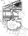
- FIG. 2 is a left side view of the engine with the chain cover and the transmission removed.
- FIG. 3 is a front view of the main body of the engine.
- FIG. 4 is a left side view of the engine with the chain cover and the transmission removed.
- FIG. 5 is a schematic front view of the rear end portion of the engine body.
- FIG. 6 is a left side view of the cylinder block of the engine.
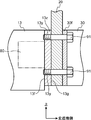
- FIG. 7 is a schematic partial longitudinal sectional view of a rear side end portion of the engine body.
- FIG. 8 is a perspective view from the right front of the cylinder block of the engine.
- FIG. 9 is a development view of the rear end portion of the engine body.
- FIG. 10 is a lower left side view of the rear end portion of the engine body (with the oil pan removed).
- FIG. 11 is a perspective view from the left front of the engine.
- the engine 1 includes an in-line 4-cylinder (first engine) mounted horizontally in an engine room 100 at the front of the vehicle so that the cylinder row direction faces the vehicle width direction.
- the engine 1 has a known structure having a piston, an injector (fuel injection valve), an intake port, an exhaust port, an intake valve, an exhaust valve, and the like inside and outside the cylinder.
- the engine 1 has an engine body 10 in which a first cylinder # 1 to a fourth cylinder # 4 are arranged in a row.
- the engine body 10 includes, in order from the top, a head cover 11, a cylinder head 12, a cylinder block 13, a lower block 14, and an oil pan 15.
- the transmission 30 is fastened with the chain cover 20 interposed between the rear end of the engine body 10 (see FIG. 1).
- the output of the engine body 10 is transmitted to the transmission 30 via the crankshaft 2 provided in the engine body 10.
- the output side of the crankshaft 2 with respect to the transmission 30 in the cylinder row direction that is, the output side (transmission side) of the engine body 10 is called the rear side of the engine body 10, and the engine body
- the side opposite to the rear side of the engine 10 is referred to as the front side of the engine body 10.
- the end of the engine main body 10 on the rear side of the engine main body 10 namely, the rear side end
- the end of the engine main body 10 on the front side of the engine main body 10 namely, the rear end
- the front end portion is referred to as the front end portion of the engine body 10.
- the “front” of the index shown in the figure indicates the front side in the vehicle front-rear direction.
- a circle represented by a chain line indicates an outer shape (for example, a pitch circle) of a flywheel 31 described later.
- the chain cover 20 is fastened over the cylinder head 12, the cylinder block 13, and the lower block 14, and the transmission 30 is fastened over the cylinder block 13 and the lower block 14.
- An intake manifold 40 is connected to a side surface of the engine body 10 on the vehicle front side
- an exhaust manifold 50 is connected to a side surface on the vehicle rear side (see FIG. 1).
- the exhaust system is disposed in the front of the vehicle and the exhaust system is disposed in the rear of the vehicle, thereby suppressing a decrease in the exhaust temperature due to traveling wind, and an exhaust purification device (not shown) provided in the exhaust system. )
- a front side accessory drive device 60 that belt drives a plurality of auxiliary machines (for example, an alternator, an air conditioner compressor, a water pump, etc.) is disposed at the front end of the engine body 10.
- a rear-side accessory driving device 70 for driving a chain of the accessory (for example, a fuel pump 80, an oil pump, a secondary balancer shaft or a primary balancer shaft) is disposed.
- the rear side accessory driving device 70 is accommodated in the chain cover 20.
- the fuel pump 80 is disposed on the vehicle front side (intake side) side surface and rear end of the engine body 10. The reason why the fuel pump 80 is disposed at this position is as follows. In order to improve the controllability of fuel injection as a measure for improving the fuel consumption of the engine 1 that directly injects fuel into the combustion chamber, high-pressure fuel injection is required, and accordingly, a fuel pump 80 that pumps fuel to the injector is necessary. Driving torque also increases. It is well known that the fuel pump 80 is disposed at the ends of the camshafts 41 and 51 and is driven using the rotation of the camshafts 41 and 51. A variable valve timing device (VVT) is attached to the camshafts 41 and 51.
- VVT variable valve timing device
- the required drive torque of the high-pressure fuel pump 80 exceeds the torque generated by the variable valve timing device, and the variable valve timing device may not be able to operate.
- the fuel pump 80 is disposed at a place other than the ends of the camshafts 41 and 51 while avoiding the high temperature portion such as the exhaust manifold 50 and the chain is driven by the crankshaft 2.
- This is disposed on the rear side of the engine body 10 on the side surface, that is, the side surface on the front side of the vehicle and on which the rear side accessory driving device 70 is disposed.
- the fuel pump 80 disposed on the vehicle front side surface and the rear side end portion of the engine main body 10 is prevented from colliding from the front of the vehicle at the time of the front collision without adding a dedicated member.
- a fuel pump 80 for pumping fuel to the injector and a starter 90 for rotating the crankshaft 2 when starting the engine are arranged at the rear end of the intake manifold mounting side surface of the engine body 10 so that the engine 1 can be protected.
- the starter 90 is disposed so as to protrude outward from the fuel pump 80 in the engine width direction orthogonal to the cylinder row direction. That is, the starter 90 is disposed so as to protrude forward of the vehicle from the fuel pump 80.
- the fuel pump 80 is disposed above the front side of the crankshaft 2 when viewed from the crankshaft direction at the rear end of the engine body 10. Is disposed below the fuel pump 80. Since the position of the fuel pump 80 is a relatively upper part of the cylinder block 13, the fuel pump 80 is disposed relatively close to the cylinder bore (not shown) in the vehicle front-rear direction.
- the position of the starter 90 is a position corresponding to the peripheral portion of the flywheel 31 (see FIGS. 4 and 5) provided concentrically with the crankshaft 2 in front of the vehicle. They are arranged relatively apart from each other in the vehicle longitudinal direction. As a result, the starter 90 is naturally arranged so as to protrude further forward of the vehicle than the fuel pump 80.
- the fuel pump 80 is attached to the cylinder block 13. Specifically, as shown in FIGS. 5 and 6, a flange-like fuel pump mounting portion 13 f that bulges forward in the vehicle is formed at the rear end of the cylinder block 13. It is attached to the attachment portion 13f from the right side of the vehicle (on the side opposite to the transmission) (see FIG. 3).
- a fastening bolt (not shown) for mounting the fuel pump 80 passes through the insertion hole formed in the mounting seat of the fuel pump 80 from the right side of the vehicle (on the side opposite to the transmission), and is screwed into the fuel pump mounting portion 13f. ing.
- the fuel pump 80 is chain driven by the crankshaft 2 by the rear side auxiliary machine driving device 70. That is, the drive shaft 81 (see FIG. 4) of the fuel pump 80 passes through the opening 13x (see FIG. 6) formed in the fuel pump mounting portion 13f and protrudes into the internal space of the chain cover 20.
- the first sprocket 82 having a relatively large diameter provided at the protruding portion and the crankshaft sprocket 3 provided at the output side end portion of the crankshaft 2 that also protrudes into the inner space of the chain cover 20 are firstly provided.
- a chain 71 is wound around.
- the fuel pump 80 is chain driven by the crankshaft 2 via the first chain 71.
- FIG. 4 the unit structure of the sprocket teeth and the chain is not shown (the same applies to FIG. 10).
- the starter 90 is attached to the chain cover 20.
- the chain cover 20 is formed with a flange-like starter mounting portion 20f that bulges toward the front of the vehicle (see FIG. 6), and the starter 90 includes the starter mounting portion 20f.
- a fastening bolt (not shown) for mounting the starter 90 passes through an insertion hole formed in the mounting seat of the starter 90 from the right side (reverse transmission side) or the left side (transmission side) of the vehicle, and the starter mounting portion 20f is screwed.
- the starter mounting portion 20f is formed in the chain cover 20 in this embodiment, but it is between the rear side end of the engine body 10 and the chain cover 20 or between the chain cover 20 and the transmission 30. It may be formed on a plate-like member (not shown) provided so as to be sandwiched between the two.
- the pinion gear of the starter 90 is formed in the peripheral portion of the flywheel 31 provided concentrically with the crankshaft 2 through the opening formed in the chain cover 20 and protruding into the internal space of the transmission 30. Is engaged with the ring gear 32 formed.
- the upper part of the engine body 10 is slanted by a predetermined angle toward the rear of the vehicle. This is mainly for securing a layout space of the intake system including the intake manifold 40 and the like arranged in front of the vehicle.
- the positional relationship between the starter 90 and the fuel pump 80 may be such that at least the starter 90 protrudes further forward of the vehicle than the fuel pump 80 when the engine body 10 is slanted.
- the intake cam shaft 41 and the exhaust cam shaft 51 disposed on the upper portion of the cylinder head 12 are chain-driven by the crankshaft 2 by the rear side accessory drive device 70. That is, a second sprocket 83 having a diameter smaller than that of the first sprocket 82 is provided in a portion of the drive shaft 81 of the fuel pump 80 that protrudes into the internal space of the chain cover 20. Of the second sprocket 83 and the intake camshaft 41, the intake camshaft sprocket 42 provided on the protruding portion of the chain cover 20 into the inner space and the exhaust camshaft 51, the inner space of the chain cover 20.
- a second chain 72 is wound around an exhaust camshaft sprocket 52 provided at the projecting portion of the second chain 72.
- the intake cam shaft 41 and the exhaust cam shaft 42 are chain driven by the crankshaft 2 via the first chain 71 and the second chain 72 wound around the fuel pump drive shaft 81.
- the rear end portion of the engine body 10 has a transmission fastening rib 13z to which the transmission 30 is fastened, and the fuel pump 80 is disposed above the starter 90 in the engine vertical direction.
- the transmission fastening rib 13z (the vehicle front portion 13z ′) exists between the fuel pump 80 and the starter 90 (see FIG. 11).
- a transmission fastening portion 13g to which the transmission 30 is fastened is provided at the rear end of the cylinder block 13, and a transmission fastening portion is provided on the outer periphery of the transmission fastening portion 13g. Ribs 13z are formed.
- the transmission fastening portion 13g has a wider area than the fuel pump attachment portion 13f, and the entire fuel pump attachment portion 13f is located within the region of the transmission fastening portion 13g as viewed in the crank axis direction.
- the transmission 30 is attached to the transmission fastening portion 13g from the left side of the vehicle (transmission side) (see FIGS. 1 and 7).
- a fastening bolt (not shown) for mounting the transmission 30 passes through an insertion hole formed in the mounting seat of the transmission 30 from the left side of the vehicle (transmission side), and is formed in the transmission fastening rib 13z. Screwed onto the boss 13y.
- the fuel pump mounting portion 13f of the cylinder block 13 is located above and behind the vehicle front portion 13z ′ of the transmission fastening rib 13z (the lower portion close to the starter 90 at the transmission side edge in FIG. 6).
- the fuel pump 80 mounted on the right side (opposite transmission side) of the vehicle is located on the right side of the starter mounting portion 20f of the chain cover 20 on the lower side and on the front side of the vehicle front portion 13z ′.
- the starter 90 attached from (1) is located. In other words, the fuel pump 80 and the starter 90 are vertically arranged with the vehicle front portion 13z 'interposed therebetween.
- a flange 30 f is formed at the end portion (right end portion in the present embodiment) of the transmission 30, and the transmission side flange 30 f and the rear end portion of the cylinder block 13 are formed.
- the fastening bolt 91 is connected to the transmission side flange 30f and the chain cover 20 (more specifically, the chain cover 20 from the left side of the vehicle (transmission side)).
- the mounting seat Through the mounting seat) and screwed into the boss 13y of the transmission fastening rib 13z.
- the transmission fastening portion 13g has a transmission fastening rib 13z on the outer peripheral portion, a plurality of boss portions 13y through which fastening bolts are inserted are provided in the rib 13z, and a fuel pump mounting portion 13f is located between two predetermined boss portions 13y among the plurality of boss portions 13y.
- the fuel pump mounting portion 13f, the opening 13x through which the fuel pump drive shaft 81 is inserted, and the fuel pump 80 are interposed therebetween.
- An upper and rear boss portion 13y ( ⁇ ) and a lower and front boss portion 13y ( ⁇ ) facing each other are provided on the transmission fastening rib 13z on the outer peripheral portion of the transmission fastening portion 13g (FIG. 4). And FIG. 11).
- the two boss portions 13y to which the fastening bolts 91 are screwed are the upper boss portion 13y ( ⁇ ) on the upper side and the lower boss portion 13y ( ⁇ ) on the lower side.
- reference numeral 13a denotes a fuel pump mounting boss.
- a pair of upper and lower fuel pump mounting boss portions 13a are provided with an opening 13x through which the fuel pump drive shaft 81 is inserted therebetween, and project from the fuel pump mounting portion 13f to the right side of the vehicle (on the opposite transmission side).
- a fastening bolt (not shown) for attaching the fuel pump 80 is screwed into the boss portion 13a from the right side of the vehicle (on the side opposite to the transmission) through an insertion hole formed in the attachment seat of the fuel pump 80.
- the crankshaft sprocket 3 provided at one end of the crankshaft 2
- the first sprocket 82 provided side by side on the drive shaft 81 of the fuel pump 80
- the second sprocket 83, the intake camshaft sprocket 42 provided on the intake camshaft 41, the first chain 71 wound around the crankshaft sprocket 3 and the first sprocket 82, the second sprocket 83 and the intake camshaft sprocket
- a second chain 72 wound around 42 is disposed.
- the second chain 72 is wound around the second sprocket 83 of the fuel pump drive shaft 81 located at the middle in the vertical direction.
- a first chain 71 is wound around the first sprocket 82 of the fuel pump drive shaft 81 and the crankshaft sprocket 3 of the crankshaft 2.
- the drive sprocket 8 of the crankshaft 2 the balancer shaft sprocket 7 of the balancer drive shaft 6 positioned relatively below the engine body 10, and the oil pump sprocket 18 of the oil pump drive shaft 17 in the oil pan 15.
- the third chain 73 is wound around.
- the fuel pump 80 is chain driven by the crankshaft 2 via the first chain 71
- the intake camshaft 41 and the exhaust camshaft 51 are chain driven by the crankshaft 2 via the first chain 71 and the second chain 72.
- the oil pump and the secondary balancer shaft or the primary balancer shaft in the oil pan 15 are chain driven by the crankshaft 2 via the third chain 73.
- the upper boss portion 13y ( ⁇ ) of the two predetermined boss portions 13y ( ⁇ ) and 13y ( ⁇ ) is located in a region surrounded by the second chain 72 (FIG. 11). reference).
- the fuel pump mounting portion 13f the opening 13x through which the fuel pump drive shaft 81 is inserted, and the upper and rear boss portions 13y ( ⁇ ) facing each other with the fuel pump 80 therebetween.
- the upper and rear boss portions 13 y ( ⁇ ) are located in a region surrounded by the second chain 72. Since the upper boss 13y ( ⁇ ) is located relatively rearward, the pair of front and rear second chains 72 extending upward from the second sprocket 83 provided on the fuel pump drive shaft 81 is also relatively It will be located behind. This means that the engagement angle of the front portion of the pair of front and rear second chain 72 extending upward from the second sprocket 83 to the intake camshaft sprocket 42 is further increased.
- the fuel pump 80 and the starter 90 are attached to the intake manifold attachment side surface of the engine 1, and a part of the intake manifold 40 is more than the fuel pump 80 when the engine 1 is viewed from the crankshaft direction. Also protrudes outward in the engine width direction, and the intake manifold 40 is disposed on the vehicle front side surface of the engine body 10 so that a part of the intake manifold overlaps the fuel pump 80 when viewed from the intake manifold mounting side surface of the engine 1. Is arranged.
- the fuel pump 80 extends in the cylinder row direction, the rear end (transmission side end) protrudes into the internal space of the chain cover 20, and the front end is the intake manifold 40. (See FIGS. 2 and 4).
- the auxiliary equipment mounting structure of the engine 1 including the transmission 30 to which the output of the engine main body 10 is transmitted via the crankshaft 2 the output side of the crankshaft 2 to the transmission 30 in the cylinder row direction is the rear side.
- a fuel pump 80 that pumps fuel to the injector at the rear end of the intake manifold mounting side of the engine body 10
- a starter 90 that rotates the crankshaft 3 when the engine is started
- the starter 90 is located outside the fuel pump 80 in the engine width direction orthogonal to the cylinder row direction. It protrudes.
- the rear end portion of the engine body 10 has a transmission fastening rib 13z to which the transmission 30 is fastened, and the fuel pump 80 is disposed above the starter 90 in the engine vertical direction.
- the transmission fastening rib 13z (the vehicle front portion 13z ′) exists between the fuel pump 80 and the starter 90.
- a transmission fastening rib 13z to which the transmission 30 is fastened and a fuel pump attachment portion 13f to which the fuel pump 80 is attached from the front side are provided at the rear end of the engine body 10.
- a part or all of the fuel pump mounting portion 13f is positioned within the region of the transmission fastening portion 13g.
- a part or all of the fuel pump 80 is attached in the region of the transmission fastening portion 13g where the rigidity is increased by fastening the transmission 30 at the rear side end portion of the engine body 10. Therefore, without increasing the number of fastening points of the fuel pump 80, vibration during driving of the fuel pump 80 and increase in the engine width are suppressed.
- the transmission fastening portion 13g has a transmission fastening rib 13z on the outer peripheral portion, and a plurality of boss portions 13y through which fastening bolts are inserted are provided in the rib 13z, and the fuel pump
- the attachment portion 13f is located between two predetermined boss portions 13y ( ⁇ ) and 13y ( ⁇ ) among the plurality of boss portions 13y.
- crankshaft sprocket 3 provided at one end of the crankshaft 2 and the first sprocket 82 provided side by side on the drive shaft 81 of the fuel pump 80.
- a second chain 72 wound around the sprocket 42 is disposed.
- the fuel pump 80 is chain driven by the crankshaft 2 via the first chain 71
- the intake camshaft 41 is chain driven by the crankshaft 2 via the first chain 71 and the second chain 72.
- the entire fuel pump 80 is attached outside the region of the transmission fastening portion 13g.
- the engagement angle of the second chain 72 to the intake camshaft sprocket 42 can be secured (that is, increased).
- both the camshafts of the intake camshaft 41 and the exhaust camshaft 51 can be driven by the second chain 72, and the gear between the camshafts becomes unnecessary, so that the gear noise is eliminated. Further, the chain pitch of the second chain 72 can be increased, and the life of the second chain 72 is extended.
- the upper boss portion 13y ( ⁇ ) of the two predetermined boss portions 13y ( ⁇ ) and 13y ( ⁇ ) is located in a region surrounded by the second chain 72.
- the fuel pump 80 and the starter 90 are attached to the intake manifold attachment side surface of the engine 1, and a part of the intake manifold 40 is more than the fuel pump 80 when the engine 1 is viewed from the crankshaft direction. Also protrudes outward in the engine width direction, and the intake manifold 40 is located on the vehicle front side of the engine body 10 so that a portion of the intake manifold 40 overlaps the fuel pump 80 when viewed from the intake manifold mounting side surface of the engine 1. It is arranged on the side. With this configuration, the intake manifold 40 is also used as a protective member for the fuel pump 80. Therefore, the fuel pump 80 can be protected from the collision object from the front of the vehicle by the intake manifold 40.
- the present invention has been described in detail with reference to the embodiments, the present invention is not limited to the above embodiments.
- all of the fuel pump mounting portion 13f is positioned within the region of the transmission fastening portion 13g as viewed in the crankshaft direction, but instead of this, a part of the fuel pump mounting portion 13f is formed. You may make it locate in the area
- the FF vehicle is an engine-side-mounted FF vehicle in which the intake system is arranged in front of the vehicle and the exhaust system is arranged in the rear of the vehicle.
- the FF vehicle is an engine-side-mounted FF vehicle in which the intake system is arranged in front of the vehicle and the exhaust system is arranged in the rear of the vehicle.
Landscapes
- Engineering & Computer Science (AREA)
- Chemical & Material Sciences (AREA)
- Combustion & Propulsion (AREA)
- Mechanical Engineering (AREA)
- General Engineering & Computer Science (AREA)
- Cylinder Crankcases Of Internal Combustion Engines (AREA)
Abstract
エンジン本体と、気筒列方向におけるエンジン本体の一端に配設され、当該エンジン本体に備えられたクランク軸を介して当該エンジン本体の出力が伝達される変速機と、を含むエンジンの補機取付構造。気筒列方向におけるクランク軸の変速機への出力側をリヤ側、反対側をフロント側と定義したときに、エンジン本体の吸気マニホールド取付側面のリヤ側端部に、インジェクタに燃料を圧送する燃料ポンプと、エンジン始動時にクランク軸を回転させるスタータとが配置され、エンジンを気筒列方向から見たときに、スタータは、気筒列方向と直交するエンジン幅方向において燃料ポンプよりも外側に突出している。
Description
本発明は、自動車等のエンジンの補機取付構造に関する。より詳しくは、インジェクタに燃料を圧送する燃料ポンプを備えたエンジンの補機取付構造に関する。
自動車等において、車両前部のエンジンルームに気筒列方向が車幅方向を向くように横置きに搭載されるエンジンがある。当該エンジンでは、シリンダブロックを含むエンジン本体の吸気側の側面を車両前方に向け、排気側の側面を車両後方に向けて、エンジンルームに搭載される。これにより、走行風による排気温度の低下を抑制して排気浄化装置の早期活性化及び活性化の維持が図られる。
その場合、ディーゼルエンジンや直噴エンジン(筒内噴射式エンジン)等のように、燃焼室に燃料を直接噴射するエンジンでは、高圧の燃料圧力が必要になるため、インジェクタに燃料を圧送する燃料ポンプの駆動負荷が大きくなる。高温を避けつつ燃料ポンプをクランク軸でチェーン駆動するためには、燃料ポンプをエンジン本体の吸気側の側面、つまり車両前方側の側面に配置することとなる。そのため、燃料ポンプを車両衝突時(前突時)の車両前方からの衝突物から保護する対策が必要になる。
この点に関し、特許文献1には、エンジン端部の車両前方側の側面に燃料ポンプを配設し、燃料ポンプの車両前面側を覆うように衝突保護用のカバープレートを配設することが開示される。これによれば、前突時に燃料ポンプがカバープレートで保護される。
上記のように、燃料ポンプがエンジン本体の車両前方側の側面かつリヤ側(気筒列方向においてクランク軸の変速機への出力側)の端部に配置される横置きエンジンでは、燃料ポンプを前突時に保護する対策が必要になる。
その場合、特許文献1のように、専用の保護部材を別途追加すると、エンジンルームが狭くなるだけでなく、エンジンの重量及びコストの増大を招く。
本発明は、インジェクタに燃料を圧送する燃料ポンプを備えたエンジンの補機取付構造に関し、車両衝突時に燃料ポンプを衝突物から保護できるエンジンの補機取付構造の提供を目的とする。
そして、本発明は、複数の気筒が列をなして配設されたエンジン本体と、気筒列方向におけるエンジン本体の一端に配設され、当該エンジン本体に備えられたクランク軸を介して当該エンジン本体の出力が伝達される変速機と、を含むエンジンの補機取付構造であって、気筒列方向のうち、前記クランク軸の変速機への出力側をリヤ側、反対側をフロント側と定義したときに、前記エンジン本体の吸気マニホールド取付側面のリヤ側端部に、インジェクタに燃料を圧送する燃料ポンプと、エンジン始動時にクランク軸を回転させるスタータとが配置され、前記エンジンを気筒列方向から見たときに、前記スタータは、気筒列方向と直交するエンジン幅方向において前記燃料ポンプよりも外側に突出しているものである。
以下、図面に基き本発明の実施形態を説明する。
図1及び図2に示すように、本実施形態に係るエンジン1は、車両前部のエンジンルーム100に、気筒列方向が車幅方向を向くように横置きに搭載された直列4気筒(第1気筒♯1~第4気筒♯4)のディーゼルエンジンである(FF車両)。エンジン1は、図示しないが、気筒内外に、ピストン、インジェクタ(燃料噴射弁)、吸気ポート、排気ポート、吸気弁、排気弁等を有する周知の構造である。
図1に示すように、エンジン1は、第1気筒♯1~第4気筒♯4が列をなして配列されたエンジン本体10を有する。エンジン本体10は、図3及び図4に示すように、上から順に、ヘッドカバー11、シリンダヘッド12、シリンダブロック13、ロアブロック14、及びオイルパン15を含み、これらで外観が形成されている。エンジン本体10のリヤ側の端部にチェーンカバー20を挟んで変速機30が締結される(図1参照)。変速機30には、エンジン本体10に備えられたクランク軸2を介して当該エンジン本体10の出力が伝達される。
なお、当実施形態の説明においては、気筒列方向における変速機30に対するクランク軸2の出力側、すなわち、エンジン本体10の出力側(変速機側)をエンジン本体10のリヤ側と呼び、エンジン本体10のリヤ側の反対側をエンジン本体10のフロント側と呼ぶ。また、エンジン本体10のリヤ側にあるエンジン本体10の端部(すなわちリヤ側端部)をエンジン本体10のリヤ端部と呼び、エンジン本体10のフロント側にあるエンジン本体10の端部(すなわちフロント側端部)をエンジン本体10のフロント端部と呼ぶ。なお、図中に示される指標の「前」は車両前後方向における前側を示している。
図4において、鎖線で表した円は、後述するフライホイール31の外形(例えばピッチ円)を示す。
図5に示すように、チェーンカバー20は、およそシリンダヘッド12、シリンダブロック13、及びロアブロック14に亘って締結され、変速機30は、シリンダブロック13及びロアブロック14に亘って締結されている。エンジン本体10の車両前方側の側面に吸気マニホールド40が接続され、車両後方側の側面に排気マニホールド50が接続されている(図1参照)。このように、FF車両では、吸気系を車両前方に、排気系を車両後方に配置することにより、走行風による排気温度の低下を抑制して、排気系に備えられる排気浄化装置(図示せず)の早期活性化及び活性化の維持が図られる。
エンジン本体10のフロント端部に、複数の補機(例えばオルタネータ、エアコンのコンプレッサ、ウォータポンプ等)をベルト駆動するフロント側補機駆動装置60が配設され、エンジン本体10のリヤ端部に複数の補機(例えば燃料ポンプ80、オイルポンプ、2次バランサ軸又は1次バランサ軸等)をチェーン駆動するリヤ側補機駆動装置70が配設される。リヤ側補機駆動装置70は上記チェーンカバー20に収容される。
燃料ポンプ80はエンジン本体10の車両前方側(吸気側)の側面かつリヤ端部に配置される。燃料ポンプ80をこの位置に配置した理由はおよそ次の通りである。燃焼室に燃料を直接噴射するエンジン1の燃費向上策として燃料噴射の制御性を高めるためには、高圧の燃料噴射が必要になり、それに伴って、インジェクタに燃料を圧送する燃料ポンプ80の必要駆動トルクも大きくなる。燃料ポンプ80をカム軸41,51端に配設し、カム軸41,51の回転を利用して駆動することが周知であるが、カム軸41,51に可変バルブタイミング装置(VVT)を取り付ける場合、高圧の燃料ポンプ80の必要駆動トルクが、可変バルブタイミング装置が発生させるトルクを上回り、可変バルブタイミング装置が作動できなくなるおそれがある。そのため、排気マニホールド50等の高温部を避けつつカム軸41,51端以外の場所に燃料ポンプ80を配設して、クランク軸2でチェーン駆動するために、燃料ポンプ80をエンジン本体10の吸気側の側面、つまり車両前方側の側面で、かつリヤ側補機駆動装置70が配設されるエンジン本体10のリヤ端部に配置したものである。ただし、その結果、燃料ポンプ80を車両衝突時(前突時)の車両前方からの衝突物から保護する対策が必要になり、その場合、専用の保護部材を別途追加すると、エンジンルーム100が狭くなるだけでなく、エンジン1の重量及びコストの増大を招く。
(1)そこで、本実施形態では、専用部材を追加することなく、エンジン本体10の車両前方側側面かつリヤ側端部に配置される燃料ポンプ80を前突時の車両前方からの衝突物から保護できるように、前記エンジン本体10の吸気マニホールド取付側面のリヤ端部に、インジェクタに燃料を圧送する燃料ポンプ80と、エンジン始動時にクランク軸2を回転させるスタータ90とが配置され、エンジン1を気筒列方向から見たときに、前記スタータ90が、気筒列方向と直交するエンジン幅方向において燃料ポンプ80よりも外側に突出して配置されている。つまり、前記スタータ90は、燃料ポンプ80よりも車両前方側に突出するように配置されている。
また、燃料ポンプ80がエンジン本体10の吸気側側面かつリヤ端部に配置される上記エンジン1では、燃料ポンプ80の駆動時の振動とエンジン幅の増大とが懸念され、その場合、振動抑制のために燃料ポンプ80の締結箇所を増やすと、部品点数及び組み付け時間の増大を招く。
(2)そこで、本実施形態では、燃料ポンプ80の締結箇所を増やすことなく、エンジン本体10の吸気側側面かつリヤ端部に配置される燃料ポンプ80の駆動時の振動とエンジン幅の増大とを抑制できるように、エンジン本体10のリヤ端部に、変速機30が締結される変速機締結用リブ13zと、フロント側から燃料ポンプ80が取り付けられる燃料ポンプ取付部13fとが設けられ、エンジン1を気筒列方向から見たときに、燃料ポンプ取付部13fの一部又は全部が、変速機締結部13gの領域内に位置するようになっている。
具体的に、図2、図4、及び図11に示すように、燃料ポンプ80は、エンジン本体10のリヤ端部においてクランク軸線方向視でクランク軸2の前側方の上方に配置され、スタータ90は、燃料ポンプ80の下方に配置されている。燃料ポンプ80の位置は、シリンダブロック13の比較的上部であるから、燃料ポンプ80は、シリンダボア(図示せず)に対して車両前後方向に相対的に近接して配置される。一方、スタータ90の位置は、クランク軸2と同心に設けられたフライホイール31(図4及び図5参照)の車両前方の周縁部に対応する位置であるから、スタータ90は、シリンダボアに対して車両前後方向に相対的に離間して配置される。その結果、スタータ90は、自ずと、燃料ポンプ80よりも車両前方側に突出するように配置される。
燃料ポンプ80はシリンダブロック13に取り付けられている。具体的には、図5及び図6に示すように、シリンダブロック13のリヤ端部に、車両前方側に膨出するフランジ状の燃料ポンプ取付部13fが形成され、燃料ポンプ80はこの燃料ポンプ取付部13fに車両右方(反変速機側)から取り付けられている(図3参照)。燃料ポンプ80を取り付けるための締結ボルト(図示せず)が車両右方(反変速機側)から燃料ポンプ80の取付座に形成された挿通孔を貫通し、燃料ポンプ取付部13fに螺合されている。
燃料ポンプ80はリヤ側補機駆動装置70によりクランク軸2でチェーン駆動される。すなわち、燃料ポンプ80の駆動軸81(図4参照)が燃料ポンプ取付部13fに形成される開口13x(図6参照)を挿通してチェーンカバー20の内部空間に突出している。そして、その突出部に設けられる相対的に大径の第1スプロケット82と、同じくチェーンカバー20の内部空間に突出するクランク軸2の出力側端部に設けられたクランク軸スプロケット3とに第1チェーン71が巻き掛けられている。これにより、燃料ポンプ80が第1チェーン71を介してクランク軸2でチェーン駆動される。なお、図4では、スプロケットの歯及びチェーンの単位構造は図示を省略してある(図10において同様)。
スタータ90はチェーンカバー20に取り付けられる。具体的に、図3及び図5に示すように、チェーンカバー20に、車両前方側に膨出するフランジ状のスタータ取付部20fが形成され(図6参照)、スタータ90はこのスタータ取付部20fに車両右方(反変速機側)から取り付けられる。スタータ90を取り付けるための締結ボルト(図示せず)が車両右方(反変速機側)又は左方(変速機側)からスタータ90の取付座に形成された挿通孔を貫通し、スタータ取付部20fに螺合されている。
なお、スタータ取付部20fは、本実施形態ではチェーンカバー20に形成されているが、エンジン本体10のリヤ側端部とチェーンカバー20との間、又は、チェーンカバー20と変速機30との間に挟み込むように設けられた板状部材(図示せず)に形成されたものであってもよい。
詳しくは図示しないが、スタータ90のピニオンギヤは、チェーンカバー20に形成された開口を挿通して変速機30の内部空間に突出し、クランク軸2と同心に設けられたフライホイール31の周縁部に形成されたリングギヤ32と噛合している。
なお、図4に示すように、エンジン本体10は上部が車両後方に所定角度だけスラントしている。これは、主として、車両前方に配置した吸気マニホールド40等を含む吸気系のレイアウトスペースを確保するためである。
なお、スタータ90と燃料ポンプ80との位置関係は、少なくとも、エンジン本体10をスラントさせたときにスタータ90が燃料ポンプ80よりも車両前方側に突出していればよい。
また、図4に示すように、シリンダヘッド12の上部に配設される吸気カム軸41及び排気カム軸51は、リヤ側補機駆動装置70によりクランク軸2でチェーン駆動される。すなわち、燃料ポンプ80の駆動軸81のうち、チェーンカバー20の内部空間への突出部には、上記第1スプロケット82よりも小径の第2スプロケット83が設けられている。そして、この第2スプロケット83と、吸気カム軸41のうち、チェーンカバー20の内部空間への突出部に設けられた吸気カム軸スプロケット42と、排気カム軸51のうち、チェーンカバー20の内部空間への突出部に設けられた排気カム軸スプロケット52とに第2チェーン72が巻き掛けられている。これにより、吸気カム軸41及び排気カム軸42が燃料ポンプ駆動軸81に巻き掛けられた第1チェーン71及び第2チェーン72を介してクランク軸2でチェーン駆動される。
(3)本実施形態では、エンジン本体10のリヤ端部は、変速機30が締結される変速機締結用リブ13zを有し、燃料ポンプ80は、エンジン上下方向においてスタータ90よりも上側に配置され、変速機締結用リブ13zの少なくとも一部(車両前方部分13z’)が、燃料ポンプ80とスタータ90との間に存在する(図11参照)。
具体的に、図6に示すように、シリンダブロック13のリヤ端部に、変速機30が締結される変速機締結部13gが設けられ、この変速機締結部13gの外周部に変速機締結用リブ13zが形成されている。変速機締結部13gは燃料ポンプ取付部13fよりも広い領域を有し、燃料ポンプ取付部13fの全部がクランク軸線方向視で変速機締結部13gの領域内に位置する。変速機30はこの変速機締結部13gに車両左方(変速機側)から取り付けられる(図1及び図7参照)。変速機30を取り付けるための締結ボルト(図示せず)が車両左方(変速機側)から変速機30の取付座に形成された挿通孔を貫通し、変速機締結用リブ13zに形成されるボス部13yに螺合される。
その上で、上記変速機締結用リブ13zの車両前方部分13z’(図6において変速機側縁部のスタータ90に近接する下部分)の上方かつ後方に、シリンダブロック13の燃料ポンプ取付部13fに車両右方(反変速機側)から取り付けられた燃料ポンプ80が位置し、上記車両前方部分13z’の下方かつ前方に、チェーンカバー20のスタータ取付部20fに車両右方(反変速機側)から取り付けられたスタータ90が位置している。言い換えると、上記車両前方部分13z’を間に挟んで燃料ポンプ80とスタータ90とが上下に配置されている。
(4)本実施形態では、変速機締結用リブ13zと変速機30との間に、エンジン本体10のリヤ側端面に配設されるチェーン71,72及びスプロケット3,42,52,82,83(言い換えるとリヤ側補機駆動装置70)を覆うチェーンカバー20が取り付けられて、上記変速機締結用リブ13zとチェーンカバー20と変速機30とが共締めされている。
具体的に、図7に示すように、変速機30の締結側の端部(本実施形態では右端部)にフランジ30fが形成され、この変速機側フランジ30fと、シリンダブロック13のリヤ端部の変速機締結用リブ13zとの間に、チェーンカバー20を挟んだ状態で、締結ボルト91が車両左方(変速機側)から変速機側フランジ30f及びチェーンカバー20(より詳しくはチェーンカバー20の取付座に形成される挿通孔)を貫通し、変速機締結用リブ13zのボス部13yに螺合されている。
(5)本実施形態では、変速機締結部13gは外周部に変速機締結用リブ13zを有し、前記リブ13zに締結ボルトが挿通される複数のボス部13yが設けられ、燃料ポンプ取付部13fは、前記複数のボス部13yのうち、所定の2つのボス部13yの間に位置している。
具体的に、図6及び図8に符号13y(α)及び13y(β)で示すように、燃料ポンプ取付部13f、燃料ポンプ駆動軸81が挿通される開口13x、及び燃料ポンプ80を間に挟んで向かい合う、上方かつ後方のボス部13y(α)と、下方かつ前方のボス部13y(β)とが、変速機締結部13gの外周部の変速機締結用リブ13zに設けられる(図4及び図11参照)。
ここで、上記図7において、締結ボルト91が螺合される2つのボス部13yは、上が上方のボス部13y(α)、下が下方のボス部13y(β)である。
なお、図8において、符号13aは、燃料ポンプ取付用ボス部である。燃料ポンプ取付用ボス部13aは、燃料ポンプ駆動軸81が挿通される開口13xを間に挟んで上下一対設けられ、燃料ポンプ取付部13fから車両右方(反変速機側)に突出している。このボス部13aに、燃料ポンプ80を取り付けるための締結ボルト(図示せず)が車両右方(反変速機側)から燃料ポンプ80の取付座に形成された挿通孔を貫通して螺合される。
(6)本実施形態では、エンジン本体10のリヤ端面に沿って、クランク軸2の一端に設けられたクランク軸スプロケット3と、燃料ポンプ80の駆動軸81に並べて設けられた第1スプロケット82及び第2スプロケット83と、吸気カム軸41に設けられた吸気カム軸スプロケット42と、クランク軸スプロケット3及び第1スプロケット82に巻き掛けられた第1チェーン71と、第2スプロケット83及び吸気カム軸スプロケット42に巻き掛けられた第2チェーン72とが配設される。
具体的に、図4、図9、及び図10に示すように、エンジン本体10の相対的に上方に位置する吸気カム軸41の吸気カム軸スプロケット42及び排気カム軸51の排気カム軸スプロケット52と、上下方向の中間部に位置する燃料ポンプ駆動軸81の第2スプロケット83とに、第2チェーン72が巻き掛けられている。また、上記燃料ポンプ駆動軸81の第1スプロケット82と、クランク軸2のクランク軸スプロケット3とに、第1チェーン71が巻き掛けられている。また、クランク軸2の駆動スプロケット8と、エンジン本体10の相対的に下方に位置するバランサ駆動軸6のバランサ軸スプロケット7と、オイルパン15内のオイルポンプ駆動軸17のオイルポンプスプロケット18とに、第3チェーン73が巻き掛けられる。これにより、燃料ポンプ80が第1チェーン71を介してクランク軸2でチェーン駆動され、吸気カム軸41及び排気カム軸51が第1チェーン71及び第2チェーン72を介してクランク軸2でチェーン駆動され、図示しないが、オイルパン15内のオイルポンプ及び2次バランサ軸又は1次バランサ軸等が第3チェーン73を介してクランク軸2でチェーン駆動される。
(7)本実施形態では、上記所定の2つのボス部13y(α)及び13y(β)のうち上方のボス部13y(α)が第2チェーン72で囲まれる領域内に位置する(図11参照)。
具体的に、図4に示すように、燃料ポンプ取付部13f、燃料ポンプ駆動軸81が挿通する開口13x、及び燃料ポンプ80を間に挟んで向かい合う、上方かつ後方のボス部13y(α)と、下方かつ前方のボス部13y(β)とのうち、上方かつ後方のボス部13y(α)が第2チェーン72で囲まれる領域内に位置している。上方のボス部13y(α)は相対的に後方に位置しているので、燃料ポンプ駆動軸81に設けられる第2スプロケット83から上方に延びる前後一対の第2チェーン72の部分もまた相対的に後方に位置していることになる。このことは、第2スプロケット83から上方に延びる前後一対の第2チェーン72の部分のうち、前側の部分の吸気カム軸スプロケット42への掛かり角がより一層大きくなることを意味する。
(8)本実施形態では、燃料ポンプ80とスタータ90は、エンジン1の吸気マニホールド取付側面に取り付けられ、エンジン1をクランク軸方向から見たときに、吸気マニホールド40の一部が燃料ポンプ80よりもエンジン幅方向外側に突出しており、エンジン1の吸気マニホールド取付側面から見たときに、吸気マニホールドの一部が燃料ポンプ80と重なるように、吸気マニホールド40が、エンジン本体10の車両前方側側面に配置されている。
具体的に、図3に示すように、燃料ポンプ80は気筒列方向に延び、リヤ端部(変速機側端部)がチェーンカバー20の内部空間に突出する一方、フロント端部が吸気マニホールド40の分岐管のアーチの下に突入する(図2及び図4参照)。
次に、本実施形態の作用を説明する。
(1)本実施形態では、複数の気筒♯1~♯4が列をなして配設されたエンジン本体10と、気筒列方向におけるエンジン本体10の一端に配設され、当該エンジン本体10に備えられたクランク軸2を介して当該エンジン本体10の出力が伝達される変速機30とを含むエンジン1の補機取付構造において、気筒列方向におけるクランク軸2の変速機30への出力側をリヤ側、反対側をフロント側と定義したときに、エンジン本体10の吸気マニホールド取付側面のリヤ端部に、インジェクタに燃料を圧送する燃料ポンプ80と、エンジン始動時にクランク軸3を回転させるスタータ90とが配置され、エンジン1を気筒列方向から見たときに、スタータ90は、気筒列方向と直交するエンジン幅方向において燃料ポンプ80よりも外側に突出している。この構成により、前突時には、燃料ポンプ80よりも先にスタータ90が車両前方からの衝突物と当接する。そのため、専用部材を追加することなく、燃料ポンプ80が保護される。
(2)本実施形態では、エンジン本体10のリヤ端部は、変速機30が締結される変速機締結用リブ13zを有し、燃料ポンプ80は、エンジン上下方向においてスタータ90よりも上側に配置され、変速機締結用リブ13zの少なくとも一部(車両前方部分13z’)が、燃料ポンプ80とスタータ90との間に存在する。この構成により、車両前方からの衝突物との当接により大荷重が加わってスタータ90が上方に変位する場合でも、スタータ90の上記変位が上記リブ13zの車両前方部分13z’によって規制される。そのため、より一層確実に燃料ポンプ80が保護される。
(3)本実施形態では、エンジン本体10のリヤ端部に、変速機30が締結される変速機締結用リブ13zと、フロント側から燃料ポンプ80が取り付けられる燃料ポンプ取付部13fとが設けられ、エンジン1を気筒列方向から見たときに、燃料ポンプ取付部13fの一部又は全部が、変速機締結部13gの領域内に位置するようになっている。この構成により、エンジン本体10のリヤ側端部において変速機30の締結により剛性が高められる変速機締結部13gの領域内に燃料ポンプ80の一部又は全部が取り付けられる。そのため、燃料ポンプ80の締結箇所を増やすことなく、燃料ポンプ80の駆動時の振動とエンジン幅の増大とが抑制される。
(4)本実施形態では、変速機締結用リブ13zと変速機30との間に、エンジン本体10のリヤ側端面に配設されるチェーン71,72及びスプロケット3,42,52,82,83を覆うチェーンカバー20が取り付けられて、上記変速機締結用リブ13zとチェーンカバー20と変速機30とが共締めされている。この構成により、上記リブ13zの剛性が高められる。そのため、スタータ90の上記変位がより一層確実に規制される。
(5)本実施形態では、前記変速機締結部13gは外周部に変速機締結用リブ13zを有し、前記リブ13zに締結ボルトが挿通される複数のボス部13yが設けられ、前記燃料ポンプ取付部13fは、前記複数のボス部13yのうち、所定の2つのボス部13y(α)及び13y(β)の間に位置する。この構成により、締結ボルトが挿通されて上記リブ13zの剛性が高められる2つのボス部13y(α)及び13y(β)の間に燃料ポンプ80が取り付けられる。そのため、燃料ポンプ80の駆動時の振動がより一層確実に抑制される。
(6)本実施形態では、エンジン本体10のリヤ側端面に沿って、クランク軸2の一端に設けられたクランク軸スプロケット3と、燃料ポンプ80の駆動軸81に並べて設けられた第1スプロケット82及び第2スプロケット83と、吸気カム軸41に設けられた吸気カム軸スプロケット42と、クランク軸スプロケット3及び第1スプロケット82に巻き掛けられた第1チェーン71と、第2スプロケット83及び吸気カム軸スプロケット42に巻き掛けられた第2チェーン72とが配設される。これにより、燃料ポンプ80が第1チェーン71を介してクランク軸2でチェーン駆動され、吸気カム軸41が第1チェーン71及び第2チェーン72を介してクランク軸2でチェーン駆動される。その場合、燃料ポンプ80の少なくとも一部がエンジン本体10のリヤ側端部において変速機締結部13gの領域内に取り付けられるので、燃料ポンプ80の全部が変速機締結部13gの領域外に取り付けられる場合(すなわち燃料ポンプ80がエンジン本体10の吸気側に突出して取り付けられる場合)に比べて、第2チェーン72の吸気カム軸スプロケット42への掛かり角が確保できる(すなわち大きくなる)。そのため、吸気カム軸41及び排気カム軸51の両方のカム軸を共に第2チェーン72で駆動でき、カム軸間ギヤが不要になるので、ギヤノイズが解消される。また、第2チェーン72のチェーンピッチを大きくすることができ、第2チェーン72の寿命が延長される。
(7)本実施形態では、上記所定の2つのボス部13y(α)及び13y(β)のうち上方のボス部13y(α)が上記第2チェーン72で囲まれる領域内に位置する。この構成により、第2チェーン72の吸気カム軸スプロケット42への掛かり角がより一層大きくなる。そのため、上記ギヤノイズの解消及びチェーン寿命の延長の作用がより一層強化される。
(8)本実施形態では、燃料ポンプ80とスタータ90は、エンジン1の吸気マニホールド取付側面に取り付けられ、エンジン1をクランク軸方向から見たときに、吸気マニホールド40の一部が燃料ポンプ80よりもエンジン幅方向外側に突出しており、エンジン1の吸気マニホールド取付側面から見たときに、吸気マニホールド40の一部が燃料ポンプ80と重なるように、吸気マニホールド40が、エンジン本体10の車両前方側側面に配置されている。この構成により、吸気マニホールド40が燃料ポンプ80の保護部材として兼用される。そのため、吸気マニホールド40で燃料ポンプ80を車両前方からの衝突物から保護することができる。
以上、実施形態を挙げて本発明を詳しく説明したが、本発明は上記実施形態に限定されない。例えば、上記実施形態では、燃料ポンプ取付部13fの全部がクランク軸線方向視で変速機締結部13gの領域内に位置するようにしたが、これに代えて、燃料ポンプ取付部13fの一部がクランク軸線方向視で変速機締結部13gの領域内に位置するようにしてもよい。
また、エンジンの配置や車両の型式は問わない。例えば、上記実施形態では、吸気系を車両前方、排気系を車両後方に配置したエンジン横置きのFF車両であったが、エンジン縦置きのFF車両でもよく、また、エンジン横置きでも、吸気系を車両後方、排気系を車両前方に配置したFF車両でもよい。
Claims (8)
- 複数の気筒が列をなして配設されたエンジン本体と、気筒列方向におけるエンジン本体の一端に配設され、当該エンジン本体に備えられたクランク軸を介して当該エンジン本体の出力が伝達される変速機と、を含むエンジンの補機取付構造であって、
気筒列方向における前記クランク軸の変速機への出力側をリヤ側、反対側をフロント側と定義したときに、
前記エンジン本体の吸気マニホールド取付側面のリヤ側端部に、インジェクタに燃料を圧送する燃料ポンプと、エンジン始動時にクランク軸を回転させるスタータとが配置され、
前記エンジンを気筒列方向から見たときに、前記スタータは、気筒列方向と直交するエンジン幅方向において前記燃料ポンプよりも外側に突出している、ことを特徴とするエンジンの補機取付構造。 - 請求項1に記載のエンジンの補機取付構造において、
前記エンジン本体のリヤ側端部は、前記変速機が締結される変速機締結用リブを有し、
前記燃料ポンプは、エンジン上下方向において前記スタータよりも上側に配置され、
前記変速機締結用リブの少なくとも一部が、前記燃料ポンプと前記スタータとの間に存在する、ことを特徴とするエンジンの補機取付構造。 - 請求項1又は2に記載のエンジンの補機取付構造において、
前記エンジン本体のリヤ側端部は、前記変速機が締結される変速機締結用リブと、フロント側から前記燃料ポンプが取り付けられる燃料ポンプ取付部とを有し、
前記エンジンを気筒列方向から見たときに、前記燃料ポンプ取付部の一部又は全部が、前記変速機締結部の領域内に位置している、ことを特徴とするエンジンの補機取付構造。 - 請求項1乃至3の何れか1項に記載のエンジンの補機取付構造において、
前記変速機締結用リブと前記変速機との間に、前記エンジン本体のリヤ側端面に配設されたチェーン及びスプロケットを覆うチェーンカバーが取り付けられて、前記変速機締結用リブと前記チェーンカバーと前記変速機とが共締めされている、ことを特徴とするエンジンの補機取付構造。 - 請求項3又は4に記載のエンジンの補機取付構造において、
前記変速機締結部は外周部に変速機締結用リブを有し、
前記リブに締結ボルトが挿通される複数のボス部が設けられ、
前記燃料ポンプ取付部は、前記複数のボス部のうち、所定の2つのボス部の間に位置する、ことを特徴とするエンジンの補機取付構造。 - 請求項5に記載のエンジンの補機取付構造において、
前記エンジン本体のリヤ側端面に沿って、
前記クランク軸の一端に設けられたクランク軸スプロケットと、
前記燃料ポンプの駆動軸に並べて設けられた第1スプロケット及び第2スプロケットと、
吸気カム軸に設けられた吸気カム軸スプロケットと、
前記クランク軸スプロケット及び第1スプロケットに巻き掛けられた第1チェーンと、
前記第2スプロケット及び吸気カム軸スプロケットに巻き掛けられた第2チェーンとが配設される、ことを特徴とするエンジンの補機取付構造。 - 請求項6に記載のエンジンの補機取付構造において、
前記所定の2つのボス部のうち上方のボス部が前記第2チェーンで囲まれる領域内に位置する、ことを特徴とするエンジンの補機取付構造。 - 請求項1乃至7の何れか1項に記載のエンジンの補機取付構造において、
前記燃料ポンプと前記スタータは、前記エンジンの吸気マニホールド取付側面に取り付けられ、
前記エンジンをクランク軸方向から見たときに、吸気マニホールドの一部が前記燃料ポンプよりもエンジン幅方向外側に突出しており、
前記エンジンの吸気マニホールド取付側面から見たときに、前記吸気マニホールドの一部が前記燃料ポンプと重なるように、前記吸気マニホールドが、前記エンジン本体の車両前方側側面に配置される、ことを特徴とするエンジンの補機取付構造。
Priority Applications (3)
| Application Number | Priority Date | Filing Date | Title |
|---|---|---|---|
| CN201680002857.4A CN107849974B (zh) | 2015-04-23 | 2016-04-21 | 发动机的附属机件安装结构 |
| DE112016000971.2T DE112016000971B4 (de) | 2015-04-23 | 2016-04-21 | Nebenaggregat-Montagestruktur für Motor |
| US15/551,646 US20180038274A1 (en) | 2015-04-23 | 2016-04-21 | Accessory mounting structure for engine |
Applications Claiming Priority (4)
| Application Number | Priority Date | Filing Date | Title |
|---|---|---|---|
| JP2015-088271 | 2015-04-23 | ||
| JP2015088270A JP6107874B2 (ja) | 2015-04-23 | 2015-04-23 | エンジンの補機レイアウト |
| JP2015088271A JP6168095B2 (ja) | 2015-04-23 | 2015-04-23 | エンジンの燃料ポンプ締結構造 |
| JP2015-088270 | 2015-04-23 |
Publications (1)
| Publication Number | Publication Date |
|---|---|
| WO2016171211A1 true WO2016171211A1 (ja) | 2016-10-27 |
Family
ID=57143983
Family Applications (1)
| Application Number | Title | Priority Date | Filing Date |
|---|---|---|---|
| PCT/JP2016/062629 Ceased WO2016171211A1 (ja) | 2015-04-23 | 2016-04-21 | エンジンの補機取付構造 |
Country Status (4)
| Country | Link |
|---|---|
| US (1) | US20180038274A1 (ja) |
| CN (1) | CN107849974B (ja) |
| DE (1) | DE112016000971B4 (ja) |
| WO (1) | WO2016171211A1 (ja) |
Cited By (1)
| Publication number | Priority date | Publication date | Assignee | Title |
|---|---|---|---|---|
| EP3521609A1 (en) * | 2018-02-02 | 2019-08-07 | Mazda Motor Corporation | Fuel supply system for engine, engine provided therewith and method of mounting an engine |
Families Citing this family (3)
| Publication number | Priority date | Publication date | Assignee | Title |
|---|---|---|---|---|
| JP6210089B2 (ja) * | 2015-05-29 | 2017-10-11 | マツダ株式会社 | エンジンの補機駆動装置 |
| JP6547797B2 (ja) | 2017-07-12 | 2019-07-24 | マツダ株式会社 | エンジンのシリンダヘッドカバー構造 |
| JP6528810B2 (ja) | 2017-07-14 | 2019-06-12 | マツダ株式会社 | エンジンのシリンダヘッドカバー構造 |
Citations (6)
| Publication number | Priority date | Publication date | Assignee | Title |
|---|---|---|---|---|
| JPH05332156A (ja) * | 1992-05-28 | 1993-12-14 | Tochigi Fuji Ind Co Ltd | 補機駆動装置 |
| JPH07103092A (ja) * | 1993-10-01 | 1995-04-18 | Toyota Motor Corp | エンジンの構造 |
| JPH11210488A (ja) * | 1998-01-28 | 1999-08-03 | Mazda Motor Corp | 燃料ポンプの保護装置 |
| JP2003083127A (ja) * | 2001-09-11 | 2003-03-19 | Toyota Motor Corp | 内燃機関の始動時制御装置及び停止時制御装置 |
| JP2004324446A (ja) * | 2003-04-22 | 2004-11-18 | Nissan Motor Co Ltd | エンジン始動装置 |
| JP2005264846A (ja) * | 2004-03-19 | 2005-09-29 | Kubota Corp | 縦型多気筒ディーゼルエンジン |
Family Cites Families (24)
| Publication number | Priority date | Publication date | Assignee | Title |
|---|---|---|---|---|
| AT265755B (de) * | 1966-01-10 | 1968-10-25 | H C Hans Dipl Ing Dr Dr List | Brennkraftmaschine mit auf einem Geräteträger angebrachten motorgeriebenen Hilfsaggregaten |
| JPH0648186A (ja) * | 1992-07-24 | 1994-02-22 | Mazda Motor Corp | 自動車のパワープラント |
| US5687690A (en) * | 1994-11-24 | 1997-11-18 | Toyota Jidosha Kabushiki Kaisha | Motor vehicle drive device |
| JP3409622B2 (ja) * | 1997-02-14 | 2003-05-26 | 日産自動車株式会社 | 燃料直接噴射式エンジン構造 |
| GB2342391A (en) | 1998-10-09 | 2000-04-12 | Cummins Engine Co Ltd | Mounting ancillary units, eg pumps, on the lateral flange of a structural engine block |
| IT1308453B1 (it) | 1999-04-23 | 2001-12-17 | Iveco Fiat | Dispositivo di trasmissione a catena per il comando delladistribuzione di un motore endotermico a due alberi a camme in testa |
| KR20030007902A (ko) * | 2000-06-08 | 2003-01-23 | 더 게이츠 코포레이션 | 통합형 동력 전달 구동 장치 및 방법 |
| JP3585818B2 (ja) * | 2000-09-12 | 2004-11-04 | 本田技研工業株式会社 | 吸気マニホールド |
| GB0106859D0 (en) * | 2001-03-20 | 2001-05-09 | Perkins Engines Co Ltd | A cylinder block extension |
| EP1291506B2 (en) * | 2001-09-11 | 2014-10-15 | Kubota Corporation | Engine |
| US20040129481A1 (en) * | 2002-12-23 | 2004-07-08 | Stolfus Kenneth R. | Sprint car torque ball housing and starter mount |
| JP4049684B2 (ja) * | 2003-02-14 | 2008-02-20 | 愛知機械工業株式会社 | エンジンの燃料系保護装置 |
| JP4670518B2 (ja) | 2005-07-08 | 2011-04-13 | マツダ株式会社 | エンジンの衝突保護構造 |
| JP5056406B2 (ja) * | 2007-02-05 | 2012-10-24 | 日産自動車株式会社 | エンジンを始動するスタータの取り付け構造 |
| JP5198204B2 (ja) * | 2008-09-30 | 2013-05-15 | 本田技研工業株式会社 | 車両用後退装置 |
| US8826877B2 (en) * | 2009-10-15 | 2014-09-09 | GM Global Technology Operations LLC | Flexible mounting system for powertrain mounted components |
| JP2011163252A (ja) * | 2010-02-12 | 2011-08-25 | Honda Motor Co Ltd | エンジン |
| US8949095B2 (en) * | 2012-01-31 | 2015-02-03 | Ford Global Technologies, Llc | Grid architecture for powertrain packaging |
| JP2013199859A (ja) * | 2012-03-23 | 2013-10-03 | Daimler Ag | 燃料噴射ポンプ |
| GB2509722B (en) * | 2013-01-10 | 2019-04-17 | Ford Global Tech Llc | A Method and Apparatus for Starting an Engine |
| JP2014227984A (ja) * | 2013-05-27 | 2014-12-08 | ダイハツ工業株式会社 | ウォータポンプの構造 |
| FR3008038B1 (fr) * | 2013-07-02 | 2016-12-02 | Technoboost | Groupe motopropulseur pour un vehicule hybride hydraulique, comprenant une machine electrique |
| US20160040643A1 (en) * | 2014-08-07 | 2016-02-11 | Borgwarner Inc. | Tandem solenoid starter having helical pinion gear and starting systems incorporating the same |
| JP6187438B2 (ja) * | 2014-11-27 | 2017-08-30 | マツダ株式会社 | エンジンの吸気装置 |
-
2016
- 2016-04-21 WO PCT/JP2016/062629 patent/WO2016171211A1/ja not_active Ceased
- 2016-04-21 DE DE112016000971.2T patent/DE112016000971B4/de not_active Expired - Fee Related
- 2016-04-21 CN CN201680002857.4A patent/CN107849974B/zh not_active Expired - Fee Related
- 2016-04-21 US US15/551,646 patent/US20180038274A1/en not_active Abandoned
Patent Citations (6)
| Publication number | Priority date | Publication date | Assignee | Title |
|---|---|---|---|---|
| JPH05332156A (ja) * | 1992-05-28 | 1993-12-14 | Tochigi Fuji Ind Co Ltd | 補機駆動装置 |
| JPH07103092A (ja) * | 1993-10-01 | 1995-04-18 | Toyota Motor Corp | エンジンの構造 |
| JPH11210488A (ja) * | 1998-01-28 | 1999-08-03 | Mazda Motor Corp | 燃料ポンプの保護装置 |
| JP2003083127A (ja) * | 2001-09-11 | 2003-03-19 | Toyota Motor Corp | 内燃機関の始動時制御装置及び停止時制御装置 |
| JP2004324446A (ja) * | 2003-04-22 | 2004-11-18 | Nissan Motor Co Ltd | エンジン始動装置 |
| JP2005264846A (ja) * | 2004-03-19 | 2005-09-29 | Kubota Corp | 縦型多気筒ディーゼルエンジン |
Cited By (1)
| Publication number | Priority date | Publication date | Assignee | Title |
|---|---|---|---|---|
| EP3521609A1 (en) * | 2018-02-02 | 2019-08-07 | Mazda Motor Corporation | Fuel supply system for engine, engine provided therewith and method of mounting an engine |
Also Published As
| Publication number | Publication date |
|---|---|
| US20180038274A1 (en) | 2018-02-08 |
| CN107849974B (zh) | 2020-05-15 |
| DE112016000971B4 (de) | 2019-12-24 |
| DE112016000971T5 (de) | 2018-01-04 |
| CN107849974A (zh) | 2018-03-27 |
Similar Documents
| Publication | Publication Date | Title |
|---|---|---|
| JP6107874B2 (ja) | エンジンの補機レイアウト | |
| CN107849974B (zh) | 发动机的附属机件安装结构 | |
| JP3711700B2 (ja) | 内燃機関のカバー装置 | |
| JP6210089B2 (ja) | エンジンの補機駆動装置 | |
| JP5120212B2 (ja) | 内燃機関 | |
| JP6761205B2 (ja) | エンジン | |
| US8256280B2 (en) | Arrangement structure for sensor to be mounted to engine of vehicle | |
| JP6168095B2 (ja) | エンジンの燃料ポンプ締結構造 | |
| US7219646B2 (en) | In-line multicylinder combustion engine | |
| CN109026322B (zh) | 发动机的冷却用油通路构造 | |
| US7325527B2 (en) | Oil pump arrangement for an internal combustion engine | |
| JP5151847B2 (ja) | 車両用エンジンのオイルフィルタ取付構造 | |
| JP2017218923A (ja) | エンジンのチェーンカバー構造 | |
| US6179582B1 (en) | Oil pump attachment structure for engine | |
| JP7275820B2 (ja) | エンジン補機の取付構造 | |
| JP2001055944A (ja) | エンジン | |
| US10914206B2 (en) | Cylinder block structure for engine | |
| JP2011089525A (ja) | 気筒休止内燃機関の補機配置構造 | |
| JP4345501B2 (ja) | エンジンの補機駆動構造 | |
| EP1785611B1 (en) | Oil pump arrangement for an internal combustion engine | |
| CN109026321B (zh) | 发动机的冷却用油通路构造 | |
| JP4433808B2 (ja) | エンジンの前部構造 | |
| JP2529893Y2 (ja) | Dohcエンジンのシリンダヘッド | |
| JP3997164B2 (ja) | エンジンの製造方法 | |
| WO2023047868A1 (ja) | 内燃機関 |
Legal Events
| Date | Code | Title | Description |
|---|---|---|---|
| 121 | Ep: the epo has been informed by wipo that ep was designated in this application |
Ref document number: 16783232 Country of ref document: EP Kind code of ref document: A1 |
|
| WWE | Wipo information: entry into national phase |
Ref document number: 15551646 Country of ref document: US |
|
| WWE | Wipo information: entry into national phase |
Ref document number: 112016000971 Country of ref document: DE |
|
| 122 | Ep: pct application non-entry in european phase |
Ref document number: 16783232 Country of ref document: EP Kind code of ref document: A1 |