WO2016159062A1 - 物体搬送装置、露光装置、フラットパネルディスプレイの製造方法、デバイス製造方法、物体搬送方法、及び露光方法 - Google Patents
物体搬送装置、露光装置、フラットパネルディスプレイの製造方法、デバイス製造方法、物体搬送方法、及び露光方法 Download PDFInfo
- Publication number
- WO2016159062A1 WO2016159062A1 PCT/JP2016/060358 JP2016060358W WO2016159062A1 WO 2016159062 A1 WO2016159062 A1 WO 2016159062A1 JP 2016060358 W JP2016060358 W JP 2016060358W WO 2016159062 A1 WO2016159062 A1 WO 2016159062A1
- Authority
- WO
- WIPO (PCT)
- Prior art keywords
- substrate
- holding
- support surface
- holding unit
- support
- Prior art date
- Legal status (The legal status is an assumption and is not a legal conclusion. Google has not performed a legal analysis and makes no representation as to the accuracy of the status listed.)
- Ceased
Links
Images









Classifications
-
- H—ELECTRICITY
- H10—SEMICONDUCTOR DEVICES; ELECTRIC SOLID-STATE DEVICES NOT OTHERWISE PROVIDED FOR
- H10P—GENERIC PROCESSES OR APPARATUS FOR THE MANUFACTURE OR TREATMENT OF DEVICES COVERED BY CLASS H10
- H10P72/00—Handling or holding of wafers, substrates or devices during manufacture or treatment thereof
- H10P72/30—Handling or holding of wafers, substrates or devices during manufacture or treatment thereof for conveying, e.g. between different workstations
-
- B—PERFORMING OPERATIONS; TRANSPORTING
- B65—CONVEYING; PACKING; STORING; HANDLING THIN OR FILAMENTARY MATERIAL
- B65G—TRANSPORT OR STORAGE DEVICES, e.g. CONVEYORS FOR LOADING OR TIPPING, SHOP CONVEYOR SYSTEMS OR PNEUMATIC TUBE CONVEYORS
- B65G49/00—Conveying systems characterised by their application for specified purposes not otherwise provided for
- B65G49/05—Conveying systems characterised by their application for specified purposes not otherwise provided for for fragile or damageable materials or articles
- B65G49/06—Conveying systems characterised by their application for specified purposes not otherwise provided for for fragile or damageable materials or articles for fragile sheets, e.g. glass
- B65G49/061—Lifting, gripping, or carrying means, for one or more sheets forming independent means of transport, e.g. suction cups, transport frames
-
- B—PERFORMING OPERATIONS; TRANSPORTING
- B65—CONVEYING; PACKING; STORING; HANDLING THIN OR FILAMENTARY MATERIAL
- B65G—TRANSPORT OR STORAGE DEVICES, e.g. CONVEYORS FOR LOADING OR TIPPING, SHOP CONVEYOR SYSTEMS OR PNEUMATIC TUBE CONVEYORS
- B65G49/00—Conveying systems characterised by their application for specified purposes not otherwise provided for
- B65G49/05—Conveying systems characterised by their application for specified purposes not otherwise provided for for fragile or damageable materials or articles
- B65G49/06—Conveying systems characterised by their application for specified purposes not otherwise provided for for fragile or damageable materials or articles for fragile sheets, e.g. glass
-
- B—PERFORMING OPERATIONS; TRANSPORTING
- B65—CONVEYING; PACKING; STORING; HANDLING THIN OR FILAMENTARY MATERIAL
- B65G—TRANSPORT OR STORAGE DEVICES, e.g. CONVEYORS FOR LOADING OR TIPPING, SHOP CONVEYOR SYSTEMS OR PNEUMATIC TUBE CONVEYORS
- B65G49/00—Conveying systems characterised by their application for specified purposes not otherwise provided for
- B65G49/05—Conveying systems characterised by their application for specified purposes not otherwise provided for for fragile or damageable materials or articles
- B65G49/06—Conveying systems characterised by their application for specified purposes not otherwise provided for for fragile or damageable materials or articles for fragile sheets, e.g. glass
- B65G49/063—Transporting devices for sheet glass
- B65G49/064—Transporting devices for sheet glass in a horizontal position
-
- B—PERFORMING OPERATIONS; TRANSPORTING
- B65—CONVEYING; PACKING; STORING; HANDLING THIN OR FILAMENTARY MATERIAL
- B65G—TRANSPORT OR STORAGE DEVICES, e.g. CONVEYORS FOR LOADING OR TIPPING, SHOP CONVEYOR SYSTEMS OR PNEUMATIC TUBE CONVEYORS
- B65G49/00—Conveying systems characterised by their application for specified purposes not otherwise provided for
- B65G49/05—Conveying systems characterised by their application for specified purposes not otherwise provided for for fragile or damageable materials or articles
- B65G49/06—Conveying systems characterised by their application for specified purposes not otherwise provided for for fragile or damageable materials or articles for fragile sheets, e.g. glass
- B65G49/063—Transporting devices for sheet glass
- B65G49/064—Transporting devices for sheet glass in a horizontal position
- B65G49/065—Transporting devices for sheet glass in a horizontal position supported partially or completely on fluid cushions, e.g. a gas cushion
-
- B—PERFORMING OPERATIONS; TRANSPORTING
- B65—CONVEYING; PACKING; STORING; HANDLING THIN OR FILAMENTARY MATERIAL
- B65G—TRANSPORT OR STORAGE DEVICES, e.g. CONVEYORS FOR LOADING OR TIPPING, SHOP CONVEYOR SYSTEMS OR PNEUMATIC TUBE CONVEYORS
- B65G49/00—Conveying systems characterised by their application for specified purposes not otherwise provided for
- B65G49/05—Conveying systems characterised by their application for specified purposes not otherwise provided for for fragile or damageable materials or articles
- B65G49/06—Conveying systems characterised by their application for specified purposes not otherwise provided for for fragile or damageable materials or articles for fragile sheets, e.g. glass
- B65G49/067—Sheet handling, means, e.g. manipulators, devices for turning or tilting sheet glass
-
- G—PHYSICS
- G02—OPTICS
- G02F—OPTICAL DEVICES OR ARRANGEMENTS FOR THE CONTROL OF LIGHT BY MODIFICATION OF THE OPTICAL PROPERTIES OF THE MEDIA OF THE ELEMENTS INVOLVED THEREIN; NON-LINEAR OPTICS; FREQUENCY-CHANGING OF LIGHT; OPTICAL LOGIC ELEMENTS; OPTICAL ANALOGUE/DIGITAL CONVERTERS
- G02F1/00—Devices or arrangements for the control of the intensity, colour, phase, polarisation or direction of light arriving from an independent light source, e.g. switching, gating or modulating; Non-linear optics
- G02F1/01—Devices or arrangements for the control of the intensity, colour, phase, polarisation or direction of light arriving from an independent light source, e.g. switching, gating or modulating; Non-linear optics for the control of the intensity, phase, polarisation or colour
- G02F1/13—Devices or arrangements for the control of the intensity, colour, phase, polarisation or direction of light arriving from an independent light source, e.g. switching, gating or modulating; Non-linear optics for the control of the intensity, phase, polarisation or colour based on liquid crystals, e.g. single liquid crystal display cells
-
- G—PHYSICS
- G03—PHOTOGRAPHY; CINEMATOGRAPHY; ANALOGOUS TECHNIQUES USING WAVES OTHER THAN OPTICAL WAVES; ELECTROGRAPHY; HOLOGRAPHY
- G03F—PHOTOMECHANICAL PRODUCTION OF TEXTURED OR PATTERNED SURFACES, e.g. FOR PRINTING, FOR PROCESSING OF SEMICONDUCTOR DEVICES; MATERIALS THEREFOR; ORIGINALS THEREFOR; APPARATUS SPECIALLY ADAPTED THEREFOR
- G03F7/00—Photomechanical, e.g. photolithographic, production of textured or patterned surfaces, e.g. printing surfaces; Materials therefor, e.g. comprising photoresists; Apparatus specially adapted therefor
- G03F7/0005—Production of optical devices or components in so far as characterised by the lithographic processes or materials used therefor
-
- G—PHYSICS
- G03—PHOTOGRAPHY; CINEMATOGRAPHY; ANALOGOUS TECHNIQUES USING WAVES OTHER THAN OPTICAL WAVES; ELECTROGRAPHY; HOLOGRAPHY
- G03F—PHOTOMECHANICAL PRODUCTION OF TEXTURED OR PATTERNED SURFACES, e.g. FOR PRINTING, FOR PROCESSING OF SEMICONDUCTOR DEVICES; MATERIALS THEREFOR; ORIGINALS THEREFOR; APPARATUS SPECIALLY ADAPTED THEREFOR
- G03F7/00—Photomechanical, e.g. photolithographic, production of textured or patterned surfaces, e.g. printing surfaces; Materials therefor, e.g. comprising photoresists; Apparatus specially adapted therefor
- G03F7/20—Exposure; Apparatus therefor
-
- G—PHYSICS
- G03—PHOTOGRAPHY; CINEMATOGRAPHY; ANALOGOUS TECHNIQUES USING WAVES OTHER THAN OPTICAL WAVES; ELECTROGRAPHY; HOLOGRAPHY
- G03F—PHOTOMECHANICAL PRODUCTION OF TEXTURED OR PATTERNED SURFACES, e.g. FOR PRINTING, FOR PROCESSING OF SEMICONDUCTOR DEVICES; MATERIALS THEREFOR; ORIGINALS THEREFOR; APPARATUS SPECIALLY ADAPTED THEREFOR
- G03F7/00—Photomechanical, e.g. photolithographic, production of textured or patterned surfaces, e.g. printing surfaces; Materials therefor, e.g. comprising photoresists; Apparatus specially adapted therefor
- G03F7/70—Microphotolithographic exposure; Apparatus therefor
-
- G—PHYSICS
- G03—PHOTOGRAPHY; CINEMATOGRAPHY; ANALOGOUS TECHNIQUES USING WAVES OTHER THAN OPTICAL WAVES; ELECTROGRAPHY; HOLOGRAPHY
- G03F—PHOTOMECHANICAL PRODUCTION OF TEXTURED OR PATTERNED SURFACES, e.g. FOR PRINTING, FOR PROCESSING OF SEMICONDUCTOR DEVICES; MATERIALS THEREFOR; ORIGINALS THEREFOR; APPARATUS SPECIALLY ADAPTED THEREFOR
- G03F7/00—Photomechanical, e.g. photolithographic, production of textured or patterned surfaces, e.g. printing surfaces; Materials therefor, e.g. comprising photoresists; Apparatus specially adapted therefor
- G03F7/70—Microphotolithographic exposure; Apparatus therefor
- G03F7/70691—Handling of masks or workpieces
- G03F7/70775—Position control, e.g. interferometers or encoders for determining the stage position
-
- G—PHYSICS
- G03—PHOTOGRAPHY; CINEMATOGRAPHY; ANALOGOUS TECHNIQUES USING WAVES OTHER THAN OPTICAL WAVES; ELECTROGRAPHY; HOLOGRAPHY
- G03F—PHOTOMECHANICAL PRODUCTION OF TEXTURED OR PATTERNED SURFACES, e.g. FOR PRINTING, FOR PROCESSING OF SEMICONDUCTOR DEVICES; MATERIALS THEREFOR; ORIGINALS THEREFOR; APPARATUS SPECIALLY ADAPTED THEREFOR
- G03F7/00—Photomechanical, e.g. photolithographic, production of textured or patterned surfaces, e.g. printing surfaces; Materials therefor, e.g. comprising photoresists; Apparatus specially adapted therefor
- G03F7/70—Microphotolithographic exposure; Apparatus therefor
- G03F7/708—Construction of apparatus, e.g. environment aspects, hygiene aspects or materials
- G03F7/70808—Construction details, e.g. housing, load-lock, seals or windows for passing light in or out of apparatus
- G03F7/70825—Mounting of individual elements, e.g. mounts, holders or supports
-
- H—ELECTRICITY
- H10—SEMICONDUCTOR DEVICES; ELECTRIC SOLID-STATE DEVICES NOT OTHERWISE PROVIDED FOR
- H10P—GENERIC PROCESSES OR APPARATUS FOR THE MANUFACTURE OR TREATMENT OF DEVICES COVERED BY CLASS H10
- H10P72/00—Handling or holding of wafers, substrates or devices during manufacture or treatment thereof
- H10P72/30—Handling or holding of wafers, substrates or devices during manufacture or treatment thereof for conveying, e.g. between different workstations
- H10P72/32—Handling or holding of wafers, substrates or devices during manufacture or treatment thereof for conveying, e.g. between different workstations between different workstations
-
- H—ELECTRICITY
- H10—SEMICONDUCTOR DEVICES; ELECTRIC SOLID-STATE DEVICES NOT OTHERWISE PROVIDED FOR
- H10P—GENERIC PROCESSES OR APPARATUS FOR THE MANUFACTURE OR TREATMENT OF DEVICES COVERED BY CLASS H10
- H10P72/00—Handling or holding of wafers, substrates or devices during manufacture or treatment thereof
- H10P72/70—Handling or holding of wafers, substrates or devices during manufacture or treatment thereof for supporting or gripping
- H10P72/76—Handling or holding of wafers, substrates or devices during manufacture or treatment thereof for supporting or gripping using mechanical means, e.g. clamps or pinches
- H10P72/7602—Handling or holding of wafers, substrates or devices during manufacture or treatment thereof for supporting or gripping using mechanical means, e.g. clamps or pinches the wafers being placed on a robot blade or gripped by a gripper for conveyance
-
- H—ELECTRICITY
- H10—SEMICONDUCTOR DEVICES; ELECTRIC SOLID-STATE DEVICES NOT OTHERWISE PROVIDED FOR
- H10P—GENERIC PROCESSES OR APPARATUS FOR THE MANUFACTURE OR TREATMENT OF DEVICES COVERED BY CLASS H10
- H10P72/00—Handling or holding of wafers, substrates or devices during manufacture or treatment thereof
- H10P72/70—Handling or holding of wafers, substrates or devices during manufacture or treatment thereof for supporting or gripping
- H10P72/76—Handling or holding of wafers, substrates or devices during manufacture or treatment thereof for supporting or gripping using mechanical means, e.g. clamps or pinches
- H10P72/7604—Handling or holding of wafers, substrates or devices during manufacture or treatment thereof for supporting or gripping using mechanical means, e.g. clamps or pinches the wafers being placed on a susceptor, stage or support
- H10P72/7608—Handling or holding of wafers, substrates or devices during manufacture or treatment thereof for supporting or gripping using mechanical means, e.g. clamps or pinches the wafers being placed on a susceptor, stage or support characterised by a plurality of separate clamping members, e.g. clamping fingers
-
- H—ELECTRICITY
- H10—SEMICONDUCTOR DEVICES; ELECTRIC SOLID-STATE DEVICES NOT OTHERWISE PROVIDED FOR
- H10P—GENERIC PROCESSES OR APPARATUS FOR THE MANUFACTURE OR TREATMENT OF DEVICES COVERED BY CLASS H10
- H10P72/00—Handling or holding of wafers, substrates or devices during manufacture or treatment thereof
- H10P72/70—Handling or holding of wafers, substrates or devices during manufacture or treatment thereof for supporting or gripping
- H10P72/76—Handling or holding of wafers, substrates or devices during manufacture or treatment thereof for supporting or gripping using mechanical means, e.g. clamps or pinches
- H10P72/7604—Handling or holding of wafers, substrates or devices during manufacture or treatment thereof for supporting or gripping using mechanical means, e.g. clamps or pinches the wafers being placed on a susceptor, stage or support
- H10P72/7612—Handling or holding of wafers, substrates or devices during manufacture or treatment thereof for supporting or gripping using mechanical means, e.g. clamps or pinches the wafers being placed on a susceptor, stage or support characterised by lifting arrangements, e.g. lift pins
-
- H—ELECTRICITY
- H10—SEMICONDUCTOR DEVICES; ELECTRIC SOLID-STATE DEVICES NOT OTHERWISE PROVIDED FOR
- H10P—GENERIC PROCESSES OR APPARATUS FOR THE MANUFACTURE OR TREATMENT OF DEVICES COVERED BY CLASS H10
- H10P95/00—Generic processes or apparatus for manufacture or treatments not covered by the other groups of this subclass
-
- B—PERFORMING OPERATIONS; TRANSPORTING
- B65—CONVEYING; PACKING; STORING; HANDLING THIN OR FILAMENTARY MATERIAL
- B65G—TRANSPORT OR STORAGE DEVICES, e.g. CONVEYORS FOR LOADING OR TIPPING, SHOP CONVEYOR SYSTEMS OR PNEUMATIC TUBE CONVEYORS
- B65G2249/00—Aspects relating to conveying systems for the manufacture of fragile sheets
- B65G2249/04—Arrangements of vacuum systems or suction cups
- B65G2249/045—Details of suction cups suction cups
Definitions
- the present invention relates to an object conveying apparatus, an exposure apparatus, a flat panel display manufacturing method, a device manufacturing method, an object conveying method, and an exposure method, and more particularly, an object conveying apparatus and method for conveying an object on a support surface,
- the present invention relates to an exposure apparatus including the object transport apparatus, an exposure method including the object transport method, and a flat panel display or device manufacturing method using the exposure apparatus or the exposure method.
- a lithography process for manufacturing an electronic device such as a liquid crystal display element, a semiconductor element (such as an integrated circuit), a mask or reticle (hereinafter collectively referred to as “mask”), a glass plate or a wafer (hereinafter referred to as “mask”).
- a step-and-scan type exposure apparatus (a so-called scanning stepper) that transfers a pattern formed on a mask onto a substrate using an energy beam while synchronously moving in a predetermined scanning direction. (Also called a scanner)).
- the present invention has been made under the circumstances described above. From a first viewpoint, the present invention holds a support portion having a support surface for supporting an object, and a part of the object located above the support surface.
- the first holding unit, the second holding unit that holds the other part of the object located above the support surface, and the second holding unit releasing the holding of the other part of the object, the object is held.
- a control device that drives and controls the first holding unit downward so that the object is supported by the support surface.
- the present invention holds a support portion having a support surface for supporting an object, a first holding portion for holding a part of the object, and the object positioned above the support surface. And a control device that drives and controls the first holding unit downward based on the fall of the other part of the object so that the object is supported by the support surface.
- a support portion having a support surface for supporting an object, a first holding portion for holding a part of the object located above the support surface, and an upper portion of the support surface.
- a second holding unit that holds the other part of the object located at a position, and the second holding unit floats and holds the other part of the object in a state where the first holding unit holds a part of the object.
- a control device that controls the drive so as to retract from the other part of the object in a state.
- a predetermined pattern is formed using an energy beam with respect to any one of the first to third object conveying devices of the present invention and the object held on the holding surface.
- An exposure apparatus comprising: a pattern forming apparatus for forming.
- the present invention is a flat panel display manufacturing method including exposing a substrate using the exposure apparatus of the present invention and developing the exposed substrate.
- the present invention is a device manufacturing method including exposing the object using the exposure apparatus of the present invention and developing the exposed object.
- a part of the object positioned above the support surface of a support unit having a support surface for supporting an object is held using a first holding unit, and the support
- the object supports the first holding part holding the object on the support surface.
- the first object conveying method includes: driving control downward as described above.
- a part of an object positioned above the support surface of a support portion having a support surface for supporting an object is held using a first holding portion, and the object
- a second object conveying method including: controlling the first holding part holding the lower part based on a drop of the other part of the object so that the object is supported by the support surface. is there.
- a part of the object positioned above the support surface of a support unit having a support surface for supporting an object is held using a first holding unit; In a state in which one holding unit holds a part of the object, the second holding unit that holds the other part of the object located above the support surface is in a state where the other part of the object is floated and held. And a third object transport method including driving control so as to retract from the other part of the object.
- a predetermined pattern is formed using an energy beam on the object supported on the support surface. Forming an exposure method.
- the present invention is a flat panel display manufacturing method including exposing a substrate using the exposure method of the present invention and developing the exposed substrate.
- the present invention is a device manufacturing method including exposing the object using the exposure method of the present invention and developing the exposed object.
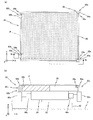
- FIG. 3A is a plan view of the substrate stage apparatus
- FIG. 3B is a cross-sectional view taken along line 3b-3b of FIG. 3A
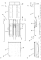
- 4A is a plan view of the substrate exchange apparatus
- FIG. 4B is a cross-sectional view taken along line 4b-4b of FIG. 4A
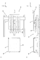
- FIG. 5A and FIG. 5B are a plan view and a side view of a liquid crystal exposure apparatus for explaining the substrate replacement operation (part 1), respectively.
- FIG. 6A and 6B are a plan view and a side view of a liquid crystal exposure apparatus for explaining the substrate replacement operation (part 2), respectively.
- FIG. 7A and FIG. 7B are a plan view and a side view of a liquid crystal exposure apparatus for explaining the substrate exchange operation (part 3), respectively.
- FIG. 8A and FIG. 8B are a plan view and a side view of a liquid crystal exposure apparatus for explaining a substrate replacement operation (part 4), respectively.
- FIG. 9A and FIG. 9B are a plan view and a side view of a liquid crystal exposure apparatus for explaining the substrate exchange operation (No. 5), respectively.
- FIG. 10A and FIG. 10B are a plan view and a side view of a liquid crystal exposure apparatus for explaining a substrate replacement operation (No. 6), respectively.
- FIGS. 11A and FIG. 11B are a plan view and a side view of a liquid crystal exposure apparatus for explaining a substrate replacement operation (part 7), respectively.
- FIGS. 12A and 12B are a plan view and a side view of a liquid crystal exposure apparatus for explaining the substrate exchange operation (No. 8), respectively.
- FIG. 13A and FIG. 13B are a plan view and a side view of a liquid crystal exposure apparatus for explaining the substrate exchanging operation (No. 9), respectively.
- FIG. 14A and FIG. 14B are a plan view and a side view of a liquid crystal exposure apparatus for explaining a substrate replacement operation (No. 10), respectively.
- FIGS. 15A and 15B are a plan view and a side view, respectively, of the liquid crystal exposure apparatus for explaining the substrate exchange operation (No.
- FIG. 16A and FIG. 16B are a plan view and a side view of a liquid crystal exposure apparatus for explaining a substrate exchange operation (part 12), respectively.
- FIGS. 17A and 17B are a plan view and a side view, respectively, of the liquid crystal exposure apparatus for explaining the substrate exchange operation (No. 13).
- FIG. 18A and FIG. 18B are a plan view and a side view of a liquid crystal exposure apparatus for explaining the substrate exchange operation (14), respectively.
- FIG. 19A and FIG. 19B are a plan view and a side view of a liquid crystal exposure apparatus for explaining a substrate exchange operation (No. 15), respectively.
- FIG. 20 (a) and 20 (b) are a plan view and a side view of a liquid crystal exposure apparatus for explaining a substrate exchange operation (16), respectively.
- FIG. 21A and FIG. 21B are a plan view and a side view of a liquid crystal exposure apparatus for explaining the substrate exchange operation (No. 17), respectively.
- FIGS. 29A and 29B are views (No. 1 and No. 2) for explaining the operation of the substrate exchange apparatus in the third embodiment.
- FIG. 1 schematically shows a configuration of a liquid crystal exposure apparatus 10 according to the first embodiment.
- the liquid crystal exposure apparatus 10 employs a step-and-scan method in which a rectangular (square) glass substrate P (hereinafter simply referred to as a substrate P) used in, for example, a liquid crystal display device (flat panel display) is an exposure object.
- a projection exposure apparatus a so-called scanner.
- the liquid crystal exposure apparatus 10 includes an illumination system 12, a mask stage apparatus 14 that holds a mask M, a projection optical system 16, and a substrate P on which a resist (sensitive agent) is coated on the surface (the surface facing the + Z side in FIG. 1). It has a substrate stage device 20 to be held, a substrate exchange device 40, and a control system thereof.
- the direction in which the mask M and the substrate P are relatively scanned with respect to the projection optical system 16 at the time of exposure is defined as the X-axis direction
- the direction orthogonal to the X-axis in the horizontal plane is defined as the Y-axis direction, the X-axis, and the Y-axis.
- the description will be made with the orthogonal direction as the Z-axis direction.
- the illumination system 12 is configured similarly to the illumination system disclosed in, for example, US Pat. No. 5,729,331.
- the illumination system 12 irradiates light emitted from a light source (not shown) (for example, a mercury lamp) through exposure mirrors (not shown), dichroic mirrors, shutters, wavelength selection filters, various lenses, and the like. ) Irradiate the mask M as IL.
- a light source for example, a mercury lamp
- the illumination light IL for example, light such as i-line (wavelength 365 nm), g-line (wavelength 436 nm), h-line (wavelength 405 nm), or the combined light of the i-line, g-line, and h-line is used.
- the mask stage device 14 holds the mask M by, for example, vacuum suction.
- the mask stage device 14 is driven with a predetermined long stroke at least in the scanning direction (X-axis direction) by, for example, a mask stage drive system (not shown) including a linear motor.
- the position information of the mask stage device 14 is obtained by a mask stage measurement system (not shown) including a linear encoder system, for example.
- the projection optical system 16 is disposed below the mask stage device 14.
- the projection optical system 16 is a so-called multi-lens projection optical system having the same configuration as the projection optical system disclosed in, for example, US Pat. No. 6,552,775, and is a double-sided telecentric equal magnification system.
- a plurality of projection optical systems for forming a vertical image are provided.
- the illumination light that has passed through the mask M causes the mask M in the illumination area to pass through the projection optical system 16.
- a projection image (partial upright image) of the circuit pattern is formed in an irradiation region (exposure region) of illumination light conjugate to the illumination region on the substrate P. Then, the mask M moves relative to the illumination area (illumination light IL) in the scanning direction, and the substrate P moves relative to the exposure area (illumination light IL) in the scanning direction. Scanning exposure of one shot area is performed, and the pattern formed on the mask M is transferred to the shot area.
- the substrate stage device 20 includes a surface plate 22, a substrate table 24, a self-weight support device 26, and a substrate holder 28.
- the surface plate 22 is composed of a rectangular plate-like member (viewed from the + Z side) arranged so that the upper surface (+ Z surface) is parallel to the XY plane, for example, via an anti-vibration device (not shown). It is installed on the floor F.
- the substrate table 24 is formed of a thin box-shaped member having a rectangular shape in plan view.
- the self-weight support device 26 is placed on the surface plate 22 in a non-contact state, and supports the self-weight of the substrate table 24 from below.
- the substrate stage device 20 includes, for example, a linear motor, and drives the substrate table 24 in the X-axis and Y-axis directions (along the XY plane) with a predetermined long stroke.
- the above-described 6 of the substrate table 24 includes a substrate stage drive system that finely drives the table 24 in directions of six degrees of freedom (X axis, Y axis, Z axis, ⁇ x, ⁇ y, and ⁇ z), and an optical interferometer system, for example.
- a substrate stage measurement system for obtaining position information in the direction of freedom is provided.
- the substrate holder 28 is made of a plate-shaped member having a rectangular shape in plan view, and the substrate P is placed on the upper surface (+ Z side surface).
- the upper surface of the substrate holder 28 is formed in a rectangle whose longitudinal direction is the X-axis direction, and its aspect ratio is substantially the same as that of the substrate P.
- the length of the long side and the short side of the upper surface of the substrate holder 28 is set somewhat shorter than the length of the long side and the short side of the substrate P, respectively. In this state, the vicinity of the four edge portions of the substrate P protrudes outward from the substrate holder 28. This is to prevent the resist applied to the surface of the substrate P from adhering to the back surface near the end of the substrate P, so that the resist does not adhere to the substrate holder 28. .
- the upper surface of the substrate holder 28 is finished extremely flat over the entire surface.
- a plurality of minute holes (not shown) for blowing air and / or for vacuum suction are formed on the upper surface of the substrate holder 28.
- the substrate holder 28 sucks air between its upper surface and the substrate P through the plurality of holes using a vacuum suction force supplied from a vacuum device (not shown), thereby substantially It is possible to flatten the entire surface following (and therefore following) the upper surface of the substrate holder 28.
- the substrate holder 28 exhausts (spouts) a pressurized gas (for example, air) supplied from a pressurized gas supply device (not shown) to the back surface of the substrate P through the hole portion, whereby the back surface of the substrate P.
- a pressurized gas for example, air
- the grounding state of the substrate P is optimized by exchanging or changing the air pressure appropriately between suction and exhaust (for example, no air pool is generated between the back surface of the substrate P and the upper surface of the substrate holder 28).
- two notches 28a are formed apart in the Y-axis direction. Further, in the vicinity of the end portion on the ⁇ X side on the upper surface of the substrate holder 28, for example, two notches 28b are formed apart from each other in the Y-axis direction.
- the notches 28a are formed at the + X side and + Y side corners of the substrate holder 28 and the + X side and ⁇ Y side corners of the substrate holder 28. Opening is performed on the + Z side surface), the + X side surface, and the + Y side (or -Y side) side surface. On the other hand, the notch 28b is opened only on the upper surface of the substrate holder 28 and the side surface on the ⁇ X side.
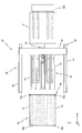
- the substrate exchange device 40 includes a beam unit 50, a substrate carry-in device 60, a substrate carry-out device 70, and a substrate assist device 80.
- the beam unit 50, the substrate carry-in device 60, and the substrate carry-out device 70 are installed at predetermined positions on the + X side of the substrate stage device 20.
- the place where the beam unit 50, the substrate carry-in device 60, and the substrate carry-out device 70 are installed in the substrate exchange device 40 will be referred to as a port unit.
- the transfer of the substrate P between an external apparatus (not shown) such as a coater / developer and the liquid crystal exposure apparatus 10 is performed at the port portion.
- the substrate carry-in device 60 is for carrying a new substrate P before exposure from the port portion to the substrate holder 28.
- the substrate carry-out device 70 is for carrying the exposed substrate P from the substrate holder 28 to the port portion.
- the substrate P is transferred between the external apparatus (not shown) and the liquid crystal exposure apparatus 10 by using the illumination system 12, the mask stage apparatus 14, the projection optical system 16, the substrate stage apparatus 20, the substrate exchange apparatus 40, etc. This is performed by the external transfer device 100 disposed outside a chamber (not shown) to be accommodated.
- the external transfer device 100 has a fork-shaped robot hand. The substrate P is placed on the robot hand, and the substrate P is transferred from the external device to the port portion in the liquid crystal exposure apparatus 10. Can be transported from the port portion to an external device.
- the beam unit 50 has a plurality (for example, six in this embodiment) of balance beams 52 arranged at predetermined intervals in the Y-axis direction.
- the balance beam 52 includes an elongated air bearing that extends in parallel with the X-axis direction, which is the transport direction of the substrate P when the substrate is replaced.
- the intervals between the plurality of balance beams 52 in the Y-axis direction can support the substrate P from below with a good balance using the plurality of balance beams 52, and as shown in FIGS. 6A and 6B, for example.
- the fork hand of the external transfer device 100 is disposed above the beam unit 50, the fork hand is set so as not to overlap with a plurality of finger portions of the fork hand.
- the length of one balance beam 52 in the longitudinal direction is slightly longer than the length in the longitudinal direction of the substrate P, and the length in the width direction is the width of the substrate P.
- the length is set to about 1/50, for example, or to about 10 to 50 times the thickness of the substrate P, for example.
- each of the plurality of balance beams 52 (overlapping in the depth direction in FIG. 4B) is a plurality of (for example, two) rod-like legs 54 extending in the Z-axis direction. Thus, it is supported from below at a position inside the both end portions in the X-axis direction.
- the plurality of legs 54 that support each balance beam 52 are connected to the vicinity of the lower ends thereof by a base plate 56 (the base plate 56 is not shown in FIG. 4A).
- the base plate 56 is driven with a predetermined stroke in the X-axis direction by an X actuator (not shown) so that the plurality of balance beams 52 integrally move with the predetermined stroke in the X-axis direction. It has become.
- the Z positions of the upper surfaces (air bearing surfaces) of the plurality of balance beams 52 are set to substantially the same position (height) as the Z position of the upper surface of the substrate holder 28.
- the substrate carry-in device 60 has a fork-like hand 62 (hereinafter referred to as a substrate carry-in hand 62) similar to the above-described external transfer device 100 (see FIGS. 1 and 2). ing.
- the substrate carry-in hand 62 includes a plurality of (for example, four in this embodiment) finger portions 62a extending in parallel with the X-axis direction, which is the carrying direction of the substrate P when carrying the substrate P into the substrate holder 28 from the port portion. Have.
- the plurality of finger portions 62a are connected to each other near the + X side end portions by a connecting member 62b.
- the ⁇ X side (substrate holder 28 (see FIG. 2 etc.) side) end of the plurality of finger portions 62a is a free end, and the space between adjacent finger portions 62a is on the substrate holder 28 side. It is open.
- Each finger portion 62a of the substrate carry-in hand 62 does not overlap with the position of the plurality of balance beams 52 in the Y-axis direction in plan view, like the robot hand (see FIG. 2) of the external transfer apparatus 100 described above. It is arranged.
- a plurality of support pads 62c for supporting the back surface of the substrate P are attached to the upper surface of each finger portion 62a.
- the connecting member 62b is made of a hollow member having a rectangular shape in plan view and a small thickness, and extends in the Y-axis direction, which is a direction perpendicular to each finger portion 62a (and the balance beam 52 described above).
- the vicinity of both ends in the Y-axis direction of the connecting member 62b is connected to an X-axis drive device 64 for driving the substrate carry-in hand 62 in the X-axis direction.
- the pair of X-axis drive devices 64 may be independently driven, or may be mechanically coupled with a gear or a belt and simultaneously driven by one drive motor.
- the pair of X-axis drive devices 64 can be moved up and down by the Z-axis drive device. Therefore, the substrate carry-in hand 62 can move between a position higher than the upper surface of the balance beam 52 (+ Z side) and a position lower than the balance beam 52 ( ⁇ Z side).
- the substrate carry-in hand 62 has a structure capable of vertical movement ( ⁇ Z-axis direction) and horizontal movement (movement in the ⁇ X-axis direction) in the substrate carry-in direction, for example, an X-axis drive device 64
- the arrangement of the Z-axis drive device may be opposite to that described above (the Z-axis drive device on the X-axis drive device 64).
- the substrate carry-out device 70 is disposed at the center of the port portion with respect to the Y-axis direction.
- three are arranged on the + Y side of the substrate carry-out device 70, and the other three are arranged on the ⁇ Y side of the substrate carry-out device 70.
- the four finger portions 62a of the substrate carry-in hand 62 provided in the substrate carry-in device 60 two are arranged on the + Y side of the substrate carry-out device 70, and the other two are ⁇ Arranged on the Y side. That is, the substrate carry-out device 70, the plurality of finger portions 62a included in the substrate carry-in hand 62, and the plurality of balance beams 52 are arranged so that their positions do not overlap with each other in the Y-axis direction.
- the substrate carry-out device 70 has, for example, one substrate carry-out hand 72. As shown in FIG. 4B, the substrate carry-out hand 72 is attached to the Z-axis drive unit 74, and the Z-axis drive unit 74 is mounted on the X-axis drive unit 76.
- the substrate carry-out hand 72 can suck and hold (hold) the substrate P using a vacuum suction force supplied from a vacuum device (not shown). Accordingly, the substrate carry-out device 70 can cause the substrate carry-out hand 72 to suck and grip the lower surface of the substrate P near the + X side end from below and move it in the X-axis direction.
- the width (Y-axis direction dimension) of the substrate carry-out hand 72 is set to be slightly wider than the width (Y-axis direction dimension) of one finger 62a of the substrate carry-in hand 62, and For example, among the six balance beams 52, the distance between the two center beams is set smaller.
- the drive stroke of the substrate carry-out hand 72 by the X-axis drive unit 76 is set to be longer than the length of the substrate P in the X-axis direction and equal to or slightly shorter than the length of the balance beam 52 in the X-axis direction.
- the X-axis drive unit 76 is installed at a position below the plurality of balance beams 52 and does not hinder the movement of the beam unit 50 (base plate 56) in the X-axis direction. Has been.
- the substrate carry-out device 70 has an alignment pad 78 that is an alignment device.
- the alignment pad 78 is attached to the Z-axis drive unit 74 via a minute drive unit 79 (not shown in FIG. 4B).
- the substrate carry-out hand 72 and the alignment pad 78 move together in the X-axis direction, but drive control in the Z-axis direction can be performed independently.
- the minute driving unit 79 minutely drives the alignment pad 78 in the Y-axis direction and the ⁇ z direction. Similar to the substrate carry-out hand 72 described above, the alignment pad 78 can also suck and hold (hold) the lower surface of the substrate P using a vacuum suction force supplied from a vacuum device (not shown).
- the substrate carry-out device 70 causes the alignment pad 78 to suck and grip the lower surface of the central portion of the substrate P from below and move it in the X-axis direction with a long stroke (or a fine stroke), the Y-axis direction, and the ⁇ z direction. Can be moved minutely.
- a plurality of substrate carry-out hands 72 may be provided at predetermined intervals in the Y-axis direction.
- the substrate carry-out hand 72 and the alignment pad 78 may be attached to an independent X-axis drive unit 76. That is, for example, an X drive unit for the alignment pad 78 is provided at the center of the port portion in the Y axis direction, and an X drive unit for the substrate carry-out hand 72 is provided on both sides (+ Y side and ⁇ Y side) in the Y axis direction.
- the plurality of balance beams 52 and the Y position may be arranged so as not to overlap each other.
- the plurality of balance beams 52 included in the beam unit 50 may be configured not only to move in the X-axis direction but also to move in the Z-axis direction. Thereby, the height can be changed in accordance with the operation at the time of delivery of the substrate P to and from the external transport apparatus 100 or the operation at the time of delivery of the substrate P to and from the substrate holder 28 (see FIG. 1). .
- the substrate assist device 80 is a device that assists the operations of the substrate carry-in device 60 and the substrate carry-out device 70 during substrate replacement.
- the substrate assist device 80 is also used for positioning the substrate P when placing the substrate P on the substrate holder 28.
- the substrate assist device 80 has a substrate stage device 20 as shown in FIGS. 3 (a) and 3 (b).
- the substrate assist device 80 includes a pair of substrate carry-out bearer devices 82a and a pair of substrate carry-in bearer devices 82b.
- the pair of substrate carry-out bearer devices 82a assists (or assists) the carry-out operation of the substrate P by the substrate carry-out device 70 (see FIG. 1 and the like), and the pair of substrate carry-in bearer devices 82b includes the substrate carry-in device 60 (see FIG. 1 and the like). Assisting (or assisting) the loading operation of the substrate P by reference).
- the substrate carry-in bearer device 82b includes a holding pad 84b, a Z actuator 86z, and an X actuator 86x.
- the holding pad 84b of one (+ Y side) substrate carry-in bearer device 82b is formed on the substrate holder 28, for example, one of the two notches 28b (+ Y side). A part is inserted into the notch 28b.
- the holding pad 84b of the other ( ⁇ Y side) substrate carry-in bearer device 82b is partially inserted into the other ( ⁇ Y side) cutout 28b.
- the holding pad 84b is made of a plate-like member having a rectangular shape in plan view, and can hold the lower surface of the substrate P by suction with a vacuum suction force supplied from a vacuum device (not shown).
- the holding pad 84b can be driven in the Z-axis direction by the Z actuator 86z.
- the holding pad 84b and the Z actuator 86z can be integrally driven in the X-axis direction by an X actuator 86x attached to the substrate table 24.
- the Z actuator 86z includes a support column that supports the holding pad 84b, and the support column is disposed outside the substrate holder 28.
- the holding pad 84b can be moved between a position contacting the lower surface of the substrate P and a position spaced apart from the lower surface of the substrate P by being driven in the notch 28b by the Z actuator 86z.
- the holding pad 84b can be driven with a long stroke between a position where a part is accommodated in the notch 28b and a position higher than the upper surface of the substrate holder 28 by the Z actuator 86z. . Further, the holding pad 84b is movable in the X axis direction by being driven integrally with the Z actuator 86z by the X actuator 86x.
- the mechanical structure of the substrate carry-out bearer device 82a is substantially the same as the substrate carry-in bearer device 82b described above. That is, as shown in FIG. 3B, the substrate carry-out bearer device 82a has a holding pad 84a partially inserted into the notch 28a, and a Z actuator 86z for driving the holding pad 84a in the Z-axis direction. And an X actuator 86x for driving the holding pad 84a in the X-axis direction.
- the movable amount in the X-axis direction of the holding pad 84a of the substrate carry-out bearer device 82a is set longer than the movable amount in the X-axis direction of the holding pad 84b of the substrate carry-in bearer device 82b.
- the movable amount in the Z-axis direction of the holding pad 84a of the substrate carry-out bearer device 82a may be shorter than the movable amount in the Z-axis direction of the holding pad 84b of the substrate carry-in bearer device 82b.
- the substrate assist device 80 assists when the substrate P (exposed substrate) is unloaded from the substrate holder 28 as follows. First, the holding pads 84a of each of the pair of substrate carry-out bearer devices 82a suck and hold, for example, two locations in the vicinity of the + X side end portion of the substrate P on the substrate holder 28. Next, with the suction and holding of the substrate P levitated and supported on the substrate holder 28 maintained, the pair of holding pads 84a are driven by a predetermined stroke (for example, about 50 mm to 100 mm) in the X-axis direction (+ X direction). To do. By driving the holding pad 84a, the substrate P is moved with respect to the substrate holder 28 by a predetermined stroke in the X-axis direction. Accordingly, the pair of substrate carry-out bearer devices 82a assists the substrate P carry-out operation by the substrate carry-out device 70 (see FIG. 1 and the like) described above.
- a predetermined stroke for example, about 50 mm to 100 mm
- the substrate assist device 80 assists when the substrate P to be placed on the substrate holder 28 is loaded. This will be outlined with reference to FIGS. 15 to 18 described later.
- First pair of substrate carry-out bearer device 82b each holding pad 84b is, the substrate carry-in device 60 of the substrate loading hand 62 substrate P 2 which is supported on (finger 62a) of, for example, near the edge of the -X side 2 The part is sucked and held (FIG. 15).
- the pair of holding pads 84b are in a state of maintaining the suction holding the substrate P 2, Z It moves by a predetermined stroke in the axial direction ( ⁇ Z direction) (FIGS. 16 to 18). With the movement of the holding pad 84b, the substrate P 2 is placed on the substrate holder 28 (FIGS. 16-18). Thereby, the pair of substrate carry-in bearer devices 82b assists the carrying-in operation of the substrate P by the above-described substrate carry-in device 60 (see FIG. 1 and the like).
- each bearer device 82a, 82b is attached to the substrate table 24 in this embodiment, but is not limited to this.
- an XY stage device for driving the substrate holder 28 or the substrate table 24 in the XY plane. (Not shown) may be attached.
- the positions and the numbers of the bearer devices 82a and 82b are not limited to this, and may be attached to the + Y side and ⁇ Y side surfaces of the substrate table 24, for example.
- the mask M is loaded onto the mask stage apparatus 14 by a mask loader (not shown) under the control of the main controller (not shown).
- the substrate exchange device 40 loads the substrate P onto the substrate holder 28.
- alignment measurement is performed by the main controller using an alignment detection system (not shown), and after completion of the alignment measurement, a plurality of shot areas set on the substrate P are sequentially exposed in a step-and-scan manner. Operation is performed. Since this exposure operation is the same as a conventional step-and-scan exposure operation, a detailed description thereof will be omitted.
- the substrate P that has been subjected to the exposure process is unloaded from the substrate holder 28 by the substrate exchange device 40, and another substrate P to be exposed next is transported to the substrate holder 28, whereby the substrate P The substrate P is exchanged, and the exposure operation and the like are continuously performed on the plurality of substrates P.
- the exchange operation of the substrate P on the substrate holder 28 in the liquid crystal exposure apparatus 10 (for convenience, a plurality of substrates P will be referred to as a substrate P 1 , a substrate P 2 , and a substrate P 3 ) will be described with reference to FIGS. This will be described with reference to b).
- the following board replacement operation is performed under the control of a main controller (not shown).
- a main controller not shown.
- Illustration of the balance beam 52 on the Y side (near side), the finger portion 62a of the substrate carry-in hand 62, and the X-axis drive device 64 (see FIG. 4A, respectively) is omitted.
- the substrate holder 28 of the substrate stage device 20 rests previously exposed substrate P 1 is, after unloading the substrate P 1 of the exposure already, the new (substrate P 1 operation will be described for mounting on another) the substrate P 2 substrate holder 28 and.
- the substrate carry-in hand 62 and the beam unit 50 included in the substrate exchange device 40 are arranged in the X position of the connecting member 62b and a plurality of positions as shown in FIG. 4A and FIG. It is assumed that the balance beam 52 is positioned so as not to overlap each other.
- the substrate exchange device 40 lowers the substrate carry-in hand ( ⁇ Z drive), and positions the upper surface of the substrate carry-in hand 62 below the lower surfaces of the plurality of balance beams 52.
- the Z position of the highest part of the substrate carry-in hand 62 includes the connection member 62b. Is set such that an interval allowing the insertion of the robot hand of the external transfer apparatus 100 is formed in the Z-axis direction.
- the beam unit 50 is driven in the + X direction. At this time, the beam unit 50 is stopped at a position where the + X side leg 54 does not contact the connecting member 62 b of the substrate carry-in hand 62. As a result, a part of the balance beams 52 (near the end on the + X side) is positioned above (+ Z side) the connecting member 62b of the substrate carry-in hand 62. This position of the beam unit 50 is a substrate delivery position with the external transfer apparatus 100.
- the robot hand of the external transport device 100 can be lowered, and passes the substrate P 2 on a plurality of balance beams 52.
- the Z position of the robot hand of the external transfer apparatus 100 is controlled so as not to come into contact with the substrate carry-in hand 62 that is waiting below the balance beam 52.
- the vicinity of the end portion of the + X side of the substrate P 2 has protrudes on the + X side from the + X side end of the plurality of balance beams 52.
- the robot hand of the external transfer apparatus 100 is driven in the + X direction, so that it exits from the port portion (from the liquid crystal exposure apparatus).
- the substrate exchanging device 40, the alignment pad 78 of the substrate carry-out device 70 is driven in the -X direction of the lower substrate P 2, it is positioned at a position facing the center portion of the substrate P 2.
- the alignment pad 78, rises (+ Z direction) is driven, between the center of the pair of balance beam 52, to adsorb grip the lower surface of the substrate P 2.
- pressurized gas is supplied to each of the plurality of balance beams 52 of the beam unit 50, and the pressurized gas is supplied to the plurality of balance beams 52. It is ejected toward the respective top to the lower surface of the substrate P 2. Accordingly, the substrate P 2 is, for a plurality of balance beams 52 and minute (for example, several hundred micrometers from a few tens of micrometers) through the gap flying.
- the pre-alignment operation is performed on the plurality of balance beams 52.
- the pre-alignment operation for example over the substrate P 2, and is disposed in each of the lower substrate P 2, by the substrate position measurement device (not shown), it is carried out while measuring the position of the substrate P 2 without contact.
- the pre-alignment during operation, the alignment pad 78 lower surface central portion adsorbed gripping of the substrate P 2 are appropriately X-axis, Y-axis, and is finely driven in the ⁇ z direction (horizontal plane directions of three degrees of freedom).
- Substrate P 2 is because it is non-contact supported by a plurality of balance beams 52, the horizontal plane in directions of three degrees of freedom position correction of the substrate P 2 (the fine positioning) can be performed with low friction.
- drives the alignment pad 78 in the -X direction is moved to the central portion of the substrate mounting surface which is formed with the substrate P 2 by a plurality of balance beams 52.
- the supply of the pressurized gas to the plurality of balance beams 52 is stopped, and the supply of the vacuum suction force to the alignment pad 78 is stopped. .
- the alignment pad 78 as spaced from the lower surface of the substrate P 2, is driven downward. Accordingly, the substrate P 2 is placed on a plurality of balance beams 52.
- the beam unit 50 is driven in the ⁇ X direction (substrate stage apparatus 20 side). In this case, the substrate P 2 and a plurality of balance beams, + end of the X-side do not overlap in the X-axis direction relative to the connecting member 62b of the substrate loading hand 62 (not to overlap in the vertical direction) position is so.
- the substrate carry-in hand 62 is driven to rise. Accordingly, the substrate P 2 on a plurality of balance beams 52, (passed to the substrate loading hand 62) is scooped upward from below by the substrate loading hand 62.
- the substrate stage device 20 performs the exposed substrate P.
- the substrate table 24 is driven in the + X direction so that the substrate holder 28 on which 1 is placed is positioned at a predetermined substrate replacement position (substrate delivery position).
- the substrate replacement position is a position on the ⁇ X side of the port portion. Note that the substrate for ease of understanding, FIG.
- FIG 5 (a) ⁇ FIG 9 (b) in the substrate holder 28 is shown in the same position, in fact, the external transport device 100 of the substrate P 2 loading has been carried out the exposure operation for the substrate P 1 passing operation and in parallel to the hand 62, the substrate holder 28 is moving in the XY plane.
- Holding pad 84a has an upper surface portion of the substrate P 1 which is vacuum suction held on the substrate holder 28 (notch 28a (FIGS. 3 (a) and 3 (b) disposed on the reference) portion), Suck and hold from the back.
- the substrate loading hand 62 supports the substrate P 2 from below, is driven in the -X direction. Accordingly, the substrate P 2 is conveyed toward the sky above the substrate holder 28 positioned at the substrate exchange position.
- the beam unit 50 is driven in the ⁇ X direction (direction approaching the substrate holder 28).
- the beam unit 50 is stopped at a predetermined position so that the ⁇ X side ends of the plurality of balance beams 52 do not come into contact with the substrate holder 28.
- the Z position on the upper surface of each of the plurality of balance beams 52 and the Z position on the upper surface of the substrate holder 28 are set to substantially the same height. Note that the substrate holder 28 may be driven in the Z-axis direction and adjusted so that they have substantially the same height.
- pressurized gas is ejected from the upper surface of the substrate holder 28 to the lower surface of the substrate P 1 .
- the friction between the upper surface of the substrate P 1 of the lower surface and the substrate holder 28 is negligible (low friction state).
- the substrate stage device 20, the holding pad 84a of the substrate carry-out bearer device 82a is, while being slightly raised driven in the + Z direction so as to follow the flying operation the substrate P 1, the adsorption part of the substrate P 1 In the gripped state, it is driven with a predetermined stroke in the + X direction (port portion side).
- the amount of movement of the holding pad 84a (that is, the substrate P 1 ) varies depending on the size of the substrate P 1 , but is set to about 50 mm to 100 mm, for example.
- near the end of the + X side of the substrate P 1 is, (overhang) projecting in the + X direction from the + X side end of the substrate holder 28 (port side).
- the portions of the substrate P 1 protruding from the substrate holder 28 are supported from below in the vicinity of the ⁇ X side ends of the plurality of balance beams 52, so that when the substrate P 1 is overhanged in advance, The pressurized gas may be ejected from the balance beam 52 as well.
- the substrate carry-in hand 62 that supports the substrate P 2 from below is stopped at a predetermined position above the substrate holder 28.
- the substrate P 2 is positioned substantially directly above the substrate holder 28 positioned at the substrate exchange position.
- the substrate stage apparatus 20 positions the substrate holder 28 so that the Y position of the substrate P 1 and the Y position of the substrate P 2 substantially coincide with each other.
- the substrates P 1 and P 2 are different in the X position at the stop position by the amount that the vicinity of the + X side end of the substrate P 1 is overhanging from the substrate holder 28, and the substrate P 2 end of the -X side, protrudes to the -X side from the end of the -X side of the substrate P 1.
- the substrate carry-out device 70 In parallel with the positioning of the substrate loading hand 62, the substrate carry-out device 70, the substrate unloading hand 72 is driven in the -X direction, of the substrate P 1, positioned below the overhanging portion from the substrate holder 28 on the + X side Is done. Further, in the substrate stage device 20, the holding pads 84b of the pair of substrate carry-in bearer devices 82b are driven up by a predetermined stroke (for example, about 50 mm to 100 mm).
- Holding pad 84b of the substrate carry bearer device 82b, as shown in FIG. 13 (a) and 13 (b), from below the substrate P 2 on the substrate loading hand 62 waiting above the substrate holder 28 Contact and hold the vicinity of the ⁇ X side end of the substrate P 2 by suction.
- the substrate carry-out device 70 In parallel with the suction holding operation of the substrate P 2 by the holding pad 84b, the substrate carry-out device 70, the substrate unloading hand 72 is driven upward, out of the exposed substrate P 1, over the substrate holder 28 on the + X side Hold the hung part by vacuum suction from the back. Further, when the substrate carry-out the hand 72 adsorbs grip the substrate P 1, the supply of vacuum suction force to the pair of substrate carry-out bearer device 82a each holding pad 84a is stopped. Thus, adsorption gripping of the substrate P 1 by the holding pad 84a is released. Holding pad 84a is to be separated from the back surface of the substrate P 1, is lowered driven.
- the substrate unloading hand 72 a central portion near the edge of the + X side of the exposed substrate P 2 in order to adsorb gripped from the back, the substrate P 2 using the substrate carry-out bearer device 82a substrate
- the holder 28 is overhanged (offset), but the present invention is not limited to this. Notches opened on the + Z side and the + X side are formed in the vicinity of the + X side end of the upper surface of the substrate holder 28, and the substrate is formed in the notch.
- the substrate carry-out hand 72 is driven to + X direction while holding the substrate P 1. Accordingly, the substrate P 1 is moved from the substrate holder 28, the beam unit 50 to the (plurality of balance beams 52) above. At this time, pressurized gas is ejected from the upper surface of each of the plurality of balance beams 52. Accordingly, the substrate P 1 is a substrate holder 28, and the beam unit 50 above, is levitation transportation in a non-contact state (excluding the portion which is held by the substrate unloading hand 72).
- each of the pair of substrate carry-out bearer devices 82a is ⁇ X so that a part thereof is accommodated in the notch 28a of the substrate holder 28 (see FIGS. 3A and 3B). Driven in the direction.
- the substrate carry-in device 60 In parallel with the unloading operation of the substrate P 1 of the substrate holder 28 by the substrate carry-out hand 72, the substrate carry-in device 60, the support pads 62c of the substrate loading hand 62, the pressure against the lower surface of the substrate P 2 A gas is blown out. As a result, the substrate P ⁇ b > 2 enters a floating (or semi-floating) state on the substrate carry-in hand 62.
- the substrate P 1 is completely carried out onto the beam unit 50 from the substrate holder 28 (as delivered) are shown states .
- the substrate P 1 is even after taken out from the substrate holder 28, substrate holder 28 is subsequently ejected pressurized gas.
- the substrate carry-in device 60, the substrate loading hand 62, a high speed and high acceleration (e.g., 1G or higher) is driven in the + X direction, it is retracted from below the substrate P 2 .
- a high speed and high acceleration e.g. 1G or higher
- the means for lowering the holding pad 84b is not particularly limited.
- position control in the Z-axis direction may be performed using a driving device such as a motor, or load control in the Z-axis direction using an air cylinder or the like.
- a control for lowering the force for raising the holding pad 84b against the gravity (force in the + Z direction) to be smaller than the downward force (force in the -Z direction) due to the weight of the substrate P) may be performed.
- a force in the + Z direction to act on the holding pad 84b of the substrate carry bearer device 82b, by releasing the rear surface of the substrate P 2 after adsorption gripping (zero), free fall the holding pad 84b with the substrate P 2 You may let them.
- each of the plurality of balance beams 52 In parallel with the loading operation the substrate P 2 using the substrate carry bearer device 82b, each of the plurality of balance beams 52, to stop the ejection of the pressurized gas. Further, the substrate carry-out device 70, thereby releasing the suction and holding of the substrate P 1 by the substrate carry-out hand 72 (FIG. 16 (a) in not shown), so as to be separated from the back surface of the substrate P 1, a substrate unloading hand 72 Drive down. As a result, the substrate P 1 is placed on the plurality of balance beams 52. Further, after hands over the substrate P 2 on the substrate holder 28 is also a substrate loading hand 62, + X are driven in the direction (after retracted from below the substrate P 1 may be decelerated).
- the holding pad 84b of each of the pair of substrate carry-in bearer devices 82b is lowered, and partly in the notch 28b (see FIG. 3A) of the substrate holder 28.
- the state where is inserted is shown.
- the substrate P 2 (excluding the portion held by the holding pad 84b) naturally falls onto the substrate holder 28 due to its own weight, but pressurized gas is ejected from the upper surface of the substrate holder 28.
- the lower surface of the lowered substrate P 1 does not contact the upper surface of the substrate holder 28 due to the static pressure of the pressurized gas.
- the substrate P 1 emerged on the substrate holder 28 via a minute gap is maintained.
- the substrate stage device 20 (or the substrate holder 28) is used by the substrate stage device 20 (the substrate holder 28 or the substrate table 24) or the substrate position measuring device (not shown) provided outside the substrate stage device 20. position of the substrate P 2 for is measured. Based on the measurement result, the holding pad 84b of each of the pair of substrate carry-in bearer devices 82b is independently driven in the X-axis direction. Accordingly, X-axis direction of the substrate P 2 with respect to the substrate stage device 20 (or the substrate holder 28), and ⁇ z directions position is corrected.
- the beam unit 50 on which the substrate P 1 is placed is driven in the + X direction and the alignment pad of the substrate carry-out device 70 in the port portion. 78 is driven in the -X direction, it is positioned at a position facing the center of the substrate P 1.
- the substrate P 2 is temporarily dropped at a position above the substrate holder 28 where a minute gap (for example, several tens of micrometers to several hundreds of micrometers) is formed between the substrate P 28 and the substrate holder 28. Since stopping the operation, it is possible to suppress the local air reservoir is generated between the substrate P 2 and the substrate holder 28. Therefore, when for holding the substrate P 2 to the substrate holder 28, it is possible to suppress deformation of the substrate P 2.
- the substrate P 2 is further evacuated from the substrate holder 28. by combining the suction may suppress deformation of the substrate P 2.
- holding pad 84b is positioned in the Y-axis direction with respect to carrying the target substrate P 2 of the substrate holder 28 as (fine alignment) capable of performing, micro drivable in the Y-axis direction It may be configured as follows. Further, in the present embodiment, the holding pad 84b has been a configuration which drives only the X-axis direction with respect to the horizontal plane, in practice, the substrate P 2 is to allow small rotational in ⁇ z direction, it is not shown However, it can be slightly displaced in the ⁇ z direction and the Y-axis direction with respect to the support of the Z actuator 86z (see FIG. 3B) by elastic deformation or the like.
- substrate stage device 20 when the substrate P is placed on the substrate holder 28, substrate holder 28 is attracted and held substrate P 2, moves to a predetermined exposure start position.
- the alignment pad 78 is driven up and sucks and grips the central portion on the back surface of the substrate P 1 from below. Further, when the alignment pad 78 sucks and holds the substrate P 1 , pressurized gas is ejected from each of the plurality of balance beams 52, whereby the substrate P 2 floats on the plurality of balance beams 52. Thereafter, by driving the alignment pad 78 to the + X direction to move the substrate P 1 to the substrate exchange position of the external transport device 100. At this time, in place, the alignment pad 78, the position in the horizontal plane of the substrate P 1 (X-axis and Y-axis direction position, and ⁇ z directions of orientation) may be modified.
- FIG. 19 (b) is shown a state in which the substrate P 1 is positioned to the substrate exchange position of the external transport device 100.
- the alignment pad 78 of the substrate carry-out device 70 is configured to cancel the suction holding of the substrate P 1, it is lowered driven so as to be separated from the substrate P 1.
- the robot hand of the external transport device 100 which holds the exposed substrate P 1, as shown in FIG. 20 (a) and FIG. 20 (b), the exit from the port unit to move the + X direction.
- the substrate carry-in hand 62 is driven downward.
- Exposed substrate P 1 is, for example, after being delivered to the external device such as a coater / developer (not shown), the robot hand of the external transport device 100 is shown in FIGS. 21 (a) and 21 (b) as such, to move toward the port portion to hold the substrate P 3 that will next exposure of the substrate P 2 is performed. Also, in the port portion, together with the substrate loading hand 62 moves downward from a plurality of balance beams 52, a plurality of balance beams 52, moves to the + X direction, receive the substrate P 3 from the robot hand of the external transport device 100 It is positioned at the substrate receiving position for. As a result, the initial state shown in FIGS. 5A and 5B is restored.
- the apparatus configuration is simple. Further, since the movement of the movable member during the substrate transfer operation from the substrate carry-in device 60 to the substrate holder 28 is small, it is possible to carry in the substrate P quickly. Further, since dust generation can be suppressed as compared with, for example, a lift pin device or the like, it is possible to suppress adhesion of dust to the substrate P.
- the substrate stage device 20 accommodates, for example, a device for receiving the substrate P from the substrate carry-in device 60 such as a lift pin device or a member (so-called substrate tray or the like) on which the substrate P is placed when the substrate P is transported.
- These holes (or recesses) may not be formed in the substrate holder 28. Therefore, almost the entire upper surface of the substrate holder 28 can be flattened except for minute holes for gas ejection and gas suction. Thereby, the plane correction of the substrate P placed on the substrate holder 28 can be reliably performed, and the exposure accuracy is improved.
- the reflectance of the exposure light and the change of reflection amount resulting from this hole part, a recessed part can be suppressed. Therefore, the uneven transfer of the mask pattern with respect to the substrate P can be suppressed.
- a pair of substrate loading bearer devices 82b provided separately from the substrate loading device 60 supporting the substrate P at the time of substrate loading are provided in the horizontal plane of the substrate P. Since the position is constrained, it is possible to suppress displacement of the substrate P in the horizontal plane due to the influence of air resistance during free fall. Therefore, the substrate P can be reliably dropped onto the substrate holder 28.
- the substrate P since the free fall of the substrate P is temporarily stopped before placing the substrate P on the substrate holder 28, when the substrate P is attracted and held by the substrate holder 28, the substrate P is placed between the substrate P and the substrate holder 28.
- the generation of the so-called air reservoir and the deformation of the substrate P caused by the air reservoir can be suppressed.
- the substrate holder 28 functions like an air bearing, so that it is possible to suppress an impact at the time of dropping.
- the pair of substrate carry-in bearer devices 82b positions the substrate with respect to the substrate holder 28. Therefore, the substrate P once placed on the substrate holder 28 is re-recovered. The possibility that the placement (reloading) needs to be performed (for example, displacement of the placement position) can be reduced. Therefore, the carrying-in operation speed of the substrate P is improved, and the overall throughput is improved.
- the substrate P tends to be thinner and lighter.
- the downward force in the gravity direction acting on the substrate P is reduced, so that the impact when the substrate P is freely dropped by its own weight and delivered to the substrate holder 28 can be reduced.
- the substrate exchanging device 40 according to the present embodiment is particularly suitable for exchanging the large-sized substrate P that is thin and light.
- abrupt dropping of the substrate P is suppressed by air resistance acting on the substrate P at the time of dropping, thereby suppressing impact when the substrate P is placed on the substrate holder 28. Therefore, it is preferable that the upper surface of the substrate holder 28 has a large number of flat regions where no recesses or holes are formed.
- a notch 28a is formed on the + X side of the substrate holder 28, and the holding pad 84a of the substrate carry-out bearer device 82a is formed in the notch 28a.
- the present invention is not limited to this.
- the substrate carry-out bearer device 82a is omitted, and the pair of substrate carry-in bearer devices 82b arranged on the ⁇ X side of the substrate holder 28 assists the substrate carry-out operation. You may do it.
- the substrate carry-in bearer device 82b grips the substrate P and moves it on the substrate holder 28 in the non-contact manner in the + X direction.
- the holder 28 is offset (overhanged) (see FIGS. 11A and 11B)
- the ejection of the pressurized gas from the substrate holder 28 is stopped, and the substrate P is placed on the substrate holder 28 again. Is done.
- the substrate carry-in bearer device 82b releases the adsorption of the substrate P, slightly descends, moves again in the ⁇ X direction, and then adsorbs and grasps a new substrate P that rises high and stands in the sky above the substrate holder 28 from below.
- the substrate carry-out hand 72 sucks and holds the vicinity of the end portion of the substrate P placed offset on the substrate holder 28 from below (see FIGS. 12A and 12B). Thereafter, pressurized gas is ejected from the substrate holder 28 and the balance beam 52, and the substrate P is carried out to the port portion in a non-contact state except for the portion held by the substrate carry-out hand 72.
- the substrate carry-out bearer device 82a is omitted (the substrate carrying-in assist device and the substrate carrying-out assist device are used in common), so the structure is simplified and the cost is reduced. be able to.
- the alignment pad 78 may be configured to be able to rotate the substrate P in the ⁇ z direction, for example, 90 °.
- the longitudinal direction from the external transfer device 100 is X
- the substrate P transported in a state parallel to the axis (horizontal state) can be rotated, for example, by 90 ° at the port portion, so that the longitudinal direction is parallel to the Y axis (vertically long state). Therefore, when the substrate P is loaded into the substrate stage device 20, it is possible to arbitrarily select whether the substrate P is loaded in a horizontally long state or a vertically long state.
- the substrate P transported to the port portion in a vertically long state by the external transport device 100 may be rotated horizontally by, for example, 90 ° in the port portion to be in a horizontally long state.
- the finger part of the robot hand of the external transfer device 100 can be shortened.
- the substrate carry-in bearer device 82 b includes a part of the holding pad 84 b in the notch 28 b formed in the substrate holder 28.
- the column member that moves up and down while supporting the holding pad 84b is disposed on the outside ( ⁇ X side) of the substrate holder 28, whereas in the second embodiment, it is shown in FIG.
- the column member 185 that moves up and down while supporting the cap 184b serving as a suction pad is located in a notch (or a through hole) formed in the substrate holder 128 in plan view ( The difference is that they are arranged (overlapping the substrate holder 128 in plan view).
- the position of the X actuator 86x and the position of the Z actuator 86z are opposite to those in the first embodiment, but the operation is the same.
- the column member 185 is cylindrical, and a suction pad called a substrate suction cap 184b is attached to the upper end side of the column member 185.
- the cap 184 b has a T-shaped XZ cross section, and when the substrate P is placed on the substrate holder 28, the cap 184 b has a tapered hole-shaped recess formed on the surface of the substrate holder 28. It is accommodated in 128b (borehole).
- the thickness of the upper half of the cap 184b is set so that the upper surface of the cap 184b and the upper surface of the substrate holder 128 are at the same height position in the state of being accommodated in the recess 128b.
- a recess is formed in the lower half of the cap 184b, and a support member 185 is inserted into the recess.
- the cap 184b and the support member 185 are mechanically separated, and a gap is provided between the cap 184b and the support member 185 to allow rotation in the ⁇ z direction around the support member 185 of the cap 184b. Is formed.
- a pipe line (not shown) is formed in the support member 185.
- a throttle hole 183 communicating with the pipe is formed in the substrate carry-in bearer device 182b.
- a shallow suction groove (or a small suction hole) for vacuum suction is formed on the surface of the cap 184b, and when the substrate P is placed on the substrate holder 128, the cap 184b Suppression can be suppressed and flatness can be maintained.
- the substrate holder 128 is formed with a pipe line 189 having one end opened in the recess 128b.
- the substrate holder 128 holds the cap 184b by vacuum suction with respect to the concave portion 128b via the pipe line 189 so that the substrate holder 128 can be reliably positioned by the concave portion 128b.
- the pipe 189 may be branched, and the branch pipe may be opened on the surface of the cap 184b through the inside of the cap 184b. In this case, the substrate P placed on the substrate holder 128 can be vacuum-sucked to follow the substrate P on the upper surface of the cap 184b.
- a tension coil spring 187 is disposed between the cap 184b and the column member 185, and the cap 184b is pressed against the concave portion 128b of the substrate holder 128 by a force attracting each other to be positioned. ing.
- the substrate carry-in bearer device 182b adsorbs the end on the ⁇ X side of the substrate P over the substrate holder 128 when the substrate P is loaded, as in the first embodiment. Hold it.
- the cap 184b rises integrally with the column member 185 and waits above the substrate holder 128. The lower surface of the substrate P is sucked and held.
- the cap 184b moves in the ⁇ Z direction as the substrate P falls freely, and the substrate is loaded before the substrate holder 128 holds the substrate P by suction.
- Performing fine alignment of the substrate P using the bearer device 182b is the same as in the first embodiment. Since the cap 184b can be rotated in the ⁇ z direction with respect to the support member 185, there is no possibility that the adsorption holding of the substrate P by the cap 184b is removed during the fine alignment operation. The slight displacement of the cap 184b in the Y direction when the substrate P moves in the ⁇ z direction can be dealt with by the backlash of the fitting between the cap 184b and the column member 185 or the deformation of the column member 185. it can.
- the cap 184b and the support member 185 are mechanically separated because the Z position of the cap 184b when the substrate P is placed on the substrate holder 128 is determined by the Z actuator. This is because it is performed accurately regardless of the Z positioning accuracy of 86z.
- the cap 184b and the support member 185 are integrated, and the lower double tube portion has a shaft longer than the outer cylinder so as to have a gap. You may make it perform operation
- the substrate carry-in bearer device 182b is separated into the cap 184b and the support member 185, and the cap 184b is embedded at the same height as the surface of the substrate holder 128.
- the recess 128b is formed on the upper surface of the substrate P, deterioration of the plane of the substrate P can be suppressed.
- the substrate P can be easily rotated by ⁇ z by driving the pair of substrate carry-in bearer devices 182b in the direction opposite to the X-axis direction.
- the gap between the outer diameter of the cap 184b and the outer diameter of the concave portion 128b of the substrate holder 128, which is necessary for the X drive of the substrate carry-in bearer device 182b to perform the alignment of the substrate P, is a reflection amount of the exposure light reflection.
- the recess 128b is formed in a tapered hole shape, the exposure light that enters perpendicularly to the surface of the substrate holder 128 does not reach the bottom of the recess 128b. . Therefore, a change in the reflection amount (light absorption) can be suppressed.
- the configuration of the substrate carry-out bearer device 182a is configured so that the cap 184a does not rotate in the ⁇ z direction because it is not necessary to rotate the substrate P in the ⁇ z direction when the substrate is loaded. Except for this point, it is the same as the substrate carry-in bearer device 182b and will not be described.
- the substrate exchanging apparatus 40 (see FIGS. 1 and 2, etc.) of the first embodiment described above waits in the sky above the substrate holder 28 almost at the same time as the substrate P on the substrate holder 28 is slightly lifted and slid out.
- the substrate carry-in hand 62 supporting the new substrate P inside is withdrawn, and the new substrate P is immediately dropped freely and placed on the substrate holder 28, so that the surface of the substrate holder 28 becomes empty and exposed to the atmosphere.
- the time spent is extremely short.
- a device for receiving the substrate P from the substrate carry-in device 60 for example, a lift pin device
- a member so-called substrate tray
- the substrate exchange apparatus 240 according to the third embodiment is different from the first embodiment in that dust on the back surface of the substrate P is removed before the substrate P is carried into the substrate holder 28.
- air bearings 252 (hereinafter referred to as R guides 252) having a circular arc shape in plan view are respectively provided on the + Y side and the ⁇ Y side of the plurality of balance beams 52. Is called).
- the width of the R guide 252 is equivalent to that of the balance beam 52.
- the R guide 252 is created by, for example, forming a plurality of minute holes after bending a hollow rod-shaped member into an arc shape by bending.
- the height position of the upper surface of the R guide 252 is set to be somewhat lower than the height position of the upper surfaces of the plurality of balance beams 52.
- the pair of R guides 252 can move in the X-axis direction integrally with the plurality of balance beams 52. 27, the substrate P is supported on the vicinity of the + Y side end portion of the + Y side R guide 252 while being placed on the plurality of balance beams 52. The vicinity of the end portion on the -Y side is supported near the end portion of the R guide 252 on the -Y side.
- the substrate P is rotated by the alignment pad 78 while exhausting pressurized gas from the plurality of balance beams 52 and the pair of R guides 252 to float the substrate P.
- the non-contact support of the pair of R guides 252 makes it possible to rotate the substrate P in the ⁇ z direction, for example, by 90 ° or more with low friction without the four corners hanging down due to its own weight.
- the back surface of the substrate P is uniformly sprayed with the pressurized gas from the balance beam 52 to all other regions except for the central portion adsorbed and held by the alignment pad 78. Thereby, the dust adhering to the back surface of the substrate P can be blown off.
- the cleaning of the back surface of the substrate P with a pressurized gas is a line for spraying a powerful jet dedicated to cleaning, apart from air exhaust at a low flow rate and flow velocity from the plurality of balance beams 52.
- a pair of nozzles 254 may be prepared, or for example, a pair of line-shaped brushes (not shown) may be prepared to directly sweep the back surface of the substrate P.
- FIG. 29A and FIG. 29B schematically show a state in which the substrate P is rotated in the ⁇ z direction, for example, 180 ° while the back surface of the substrate P is cleaned with line-shaped high-pressure air or a brush. It is shown. 29A and 29B, reference numeral 254 indicates a range in which pressurized air is ejected from a pair of nozzles 254 (see FIG. 28) or a pair of brushes (not shown).
- FIG. 29A shows an initial state
- FIG. 29B shows a cleaning locus when the substrate P is rotated, for example, 180 °.
- FIG. 29B shows a diagram in which a pair of nozzles 254 (see FIG. 28) or a pair of brushes are rotated, for example, every 15 ° instead of the substrate P rotating for easy understanding.
- the rotation of the pair of nozzles 254 or the pair of brushes is continuously performed, it can be seen that almost the entire surface of the substrate P can be cleaned except for the central portion by being attracted by the alignment pad 78. .
- the substrate P can be rotated on the plurality of balance beams 52 by, for example, 90 ° or more, and air can be blown over the entire back surface of the substrate P.
- the temperature of the substrate P can be adjusted to a predetermined uniform temperature. As a result, high-accuracy exposure can be performed while suppressing thermal contraction of the substrate P during standby at the port portion.
- the holding pads 84b of each of the pair of substrate carry-in bearer devices 82b that are spaced apart in the Y-axis direction are used to hold the two locations that are separated in the Y-axis direction of the substrate P.
- substrate P is not restricted to this, For example, you may hold
- the holding surface of the holding pad 84b may be shaped to extend in the Y-axis direction.
- the substrate carry-in bearer device 82b is configured to restrain (hold) the ⁇ X direction side end portion of the substrate P, but is not limited thereto.
- You may comprise so that the corner
- the location (place) where the substrate carry-in bearer device 82b restrains the substrate P can be installed so long as it does not interfere with the operation of the substrate carry-out bearer device 82a, the substrate carry-out device 70, and the substrate carry-in device 60. Any of these parts or corners, or any combination thereof may be used.
- substrate carrying-in bearer apparatus 82b was accommodated in the corresponding notch 28b, it is not restricted to this,
- substrate holder 28 is previously stored. A portion protruding from the vicinity of the end may be held by suction. In this case, it is not necessary to form the notch 28b in the substrate holder 28. Since the protruding portion has a small area, in order to secure a contact area between the holding pad 84b and the substrate P, the holding surface of the holding pad 84b may have a shape extending in the Y-axis direction.
- the holding pad 84 b may be pulled out after the holding pad 84 b is sandwiched between the back surface of the substrate P and the upper surface of the substrate holder 28. Also in this case, it is not necessary to form the notch 28b in the substrate holder 28. At this time, a part of the substrate P may be sucked and held so that the substrate P does not move when the holding pad 84b is pulled out.
- the substrate P to be unloaded is set in an offset state (a state in which a part of the substrate P protrudes from the substrate holder 28) by the substrate unloading bearer device 82a.
- the substrate P may be tilted around the axis to incline the upper surface of the substrate holder 28, and the substrate P may be offset by its own weight.
- the substrate carry-out device 70 holds the vicinity of the offset end of the substrate P and carries the substrate P, but sucks and holds the portion of the substrate P that protrudes from the vicinity of the end of the substrate holder 28 in advance. Also good.
- the operation of setting the substrate P in the offset state by the substrate carry-out bearer device 82a may be performed while the substrate holder 28 is moved to the substrate replacement position (in parallel with the movement of the substrate holder 28).
- the substrate carry-in device 60 carried the substrate P using the substrate carry-in hand 62 that supports the substrate P from below in the direction of gravity.
- the configuration of the transfer device is not limited to this, and the substrate P may be suspended and supported from above in the direction of gravity using, for example, a known Bernoulli chuck. In this case, the substrate P can be dropped by its own weight by releasing the suspension support of the substrate P by the Bernoulli chuck.
- the Bernoulli chuck method in order to constrain the position of the substrate P in the XY plane above the substrate holder 28, there is some transfer assist mechanism that replaces the substrate carry-in bearer device 82b in the above embodiment. I need it.
- this transport assist mechanism for example, a wall member for physically limiting the side surface of the substrate P may be formed in the peripheral portion of the Bernoulli chuck.
- the Bernoulli chuck may be provided with a mechanism that blows air for restraining the position in the XY plane against the side surface of the substrate P.
- the substrate unloading hand 72 is driven in the + X direction (from the substrate holder 28 of the substrate P 1 by the substrate unloading hand 72).
- substrate after the start of the referred to as "pull-out operation" of the unloading operation / substrate unloading hand 72 when retracting operation / words from below the substrate P 2 of the substrate carry-+ drive in the X direction of the hand 62 (substrate loading hand 62 It has been described as to initiate referred to as "pull-out operation") of the carry-in operation / substrate loading hand 62 to loading hand 62 substrate holder to 28 of the substrate P 2 by, but the timing of the withdrawal operation is not limited thereto.
- the starting order of the drawing operation may be either first or simultaneously.
- the substrate holder 28 is configured to hold the substrate P by suction, but is not limited thereto, and for example, the substrate P may be held in a non-contact state.
- the substrate carry-in bearer device 82b for restraining the position of the substrate P in the XY plane above the substrate holder 28 is provided in the substrate holder 28 (substrate stage device 20).
- the substrate carry-in device 60 may be included, or may be supported by being suspended above a substrate replacement position by a frame member that constitutes a chamber that accommodates the substrate stage device 20, for example.
- the substrate load device 60 transports the substrate P over the substrate holder 28.
- the robot hand of the external transfer device 100 may transfer the substrate P to be transferred over the substrate holder 28 and directly deliver the substrate P to the substrate transfer bearer device 82b.
- the wavelength of the light source used in the illumination system 12 and the illumination light IL emitted from the light source is not particularly limited.
- ultraviolet light such as ArF excimer laser light (wavelength 193 nm), KrF excimer laser light (wavelength 248 nm), or the like. It may be vacuum ultraviolet light such as light or F 2 laser light (wavelength 157 nm).
- the projection optical system 16 is an equal magnification system.
- the present invention is not limited to this, and a reduction system or an enlargement system may be used.
- the use of the exposure apparatus is not limited to an exposure apparatus for liquid crystal that transfers a liquid crystal display element pattern onto a square glass plate.
- an exposure apparatus for manufacturing an organic EL (Electro-Luminescence) panel, a semiconductor The present invention can be widely applied to an exposure apparatus for manufacturing, an exposure apparatus for manufacturing a thin film magnetic head, a micromachine, a DNA chip, and the like.
- an exposure apparatus for manufacturing a thin film magnetic head a micromachine, a DNA chip, and the like.
- the present invention can also be applied to an exposure apparatus that transfers a circuit pattern.
- the object to be exposed is not limited to the glass plate, but may be another object such as a wafer, a ceramic substrate, a film member, or a mask blank.
- the thickness of the substrate is not particularly limited, and includes, for example, a film-like (flexible sheet-like member).
- the exposure apparatus of the present embodiment is particularly effective when a substrate having a side length or diagonal length of 500 mm or more is an exposure target.
- the step of designing the function and performance of the device the step of producing a mask (or reticle) based on this design step, and the step of producing a glass substrate (or wafer)
- the above-described exposure method is executed using the exposure apparatus of the above embodiment, and a device pattern is formed on the glass substrate. Therefore, a highly integrated device can be manufactured with high productivity. .
- the object conveying method and apparatus of the present invention are suitable for conveying an object.
- the exposure apparatus of the present invention is suitable for exposing an object.
- the manufacturing method of the flat panel display of this invention is suitable for manufacture of a flat panel display.
- the vice manufacturing method of the present invention is suitable for manufacturing a micro device.
- SYMBOLS 10 Liquid crystal exposure apparatus, 20 ... Substrate stage apparatus, 40 ... Substrate exchange apparatus, 50 ... Beam unit, 60 ... Substrate carry-in apparatus, 70 ... Substrate carry-out apparatus, 80 ... Substrate assist apparatus, 82a ... Substrate carry-out bearer apparatus, 82b ... Substrate carrying bearer device, P ... substrate.
Landscapes
- Physics & Mathematics (AREA)
- General Physics & Mathematics (AREA)
- Nonlinear Science (AREA)
- Engineering & Computer Science (AREA)
- Epidemiology (AREA)
- Public Health (AREA)
- Environmental & Geological Engineering (AREA)
- Chemical & Material Sciences (AREA)
- Crystallography & Structural Chemistry (AREA)
- Health & Medical Sciences (AREA)
- Optics & Photonics (AREA)
- Container, Conveyance, Adherence, Positioning, Of Wafer (AREA)
- Exposure And Positioning Against Photoresist Photosensitive Materials (AREA)
- Robotics (AREA)
Abstract
Description
以下、第1の実施形態について、図1~図21(b)を用いて説明する。
また、本実施形態において、保持パッド84bは、水平面内に関してX軸方向のみへ駆動する構成であったが、実際には、基板P2がθz方向に微少回転可能なように、不図示であるが、弾性変形などによってZアクチュエータ86z(図3(b)参照)の支柱に対して、微少にθz方向、及びY軸方向に変位が可能なようになっている。
次に、第2の実施形態に係る液晶露光装置ついて、図23~図25を用いて説明する。第2の実施形態に係る液晶露光装置の構成は、基板交換装置の一部の構成及び動作が異なる点を除き、上記第1の実施形態と同じであるので、以下、相違点についてのみ説明し、上記第1の実施形態と同じ構成及び機能を有する要素については、上記第1の実施形態と同じ符号を付してその説明を省略する。
次に、第3の実施形態に係る液晶露光装置ついて、図26~図29(b)を用いて説明する。第3の実施形態に係る液晶露光装置の構成は、基板交換装置の一部の構成及び動作が異なる点を除き、上記第1の実施形態と同じであるので、以下、相違点についてのみ説明し、上記第1の実施形態と同じ構成及び機能を有する要素については、上記第1の実施形態と同じ符号を付してその説明を省略する。
Claims (60)
- 物体を支持する支持面を有する支持部と、
前記支持面の上方に位置する前記物体の一部を保持する第1保持部と、
前記支持面の上方に位置する前記物体の他部を保持する第2保持部と、
前記第2保持部による前記物体の他部の保持を解除すると、前記物体を保持した前記第1保持部を、前記物体が前記支持面に支持されるように下方へ駆動制御する制御装置と、を備える物体搬送装置。 - 前記制御装置は、前記第1保持部を前記物体の他部の落下に基づいて下方へ駆動制御する請求項1に記載の物体搬送装置。
- 前記第2保持部は、前記物体の他部を浮上保持可能に保持し、
前記制御装置は、前記第2保持部が前記物体の他部を浮上保持させた状態で前記物体の他部から退避するように駆動する請求項1又は2に記載の物体搬送装置。 - 前記制御装置は、前記物体と前記支持面との間に介在する気体により前記物体が変形しないように前記第1保持部を駆動する請求項1から3の何れか一項に記載の物体搬送装置。
- 前記支持部は、前記支持面から前記物体に対して気体を供給する供給孔と、前記支持面と前記物体との間の気体を吸引する吸引孔と、を有し、
前記保持部に保持された前記物体と前記支持面との間の気体の量を変化させる請求項4に記載の物体搬送装置。 - 前記支持部を駆動する駆動装置をさらに備え、
前記駆動装置は、前記支持面に平行な面に沿って移動可能であり、
前記第1保持部は、前記支持部に対して所定の位置関係で前記面に沿って移動可能である請求項1から5の何れか一項に記載の物体搬送装置。 - 前記制御装置は、前記駆動装置により前記支持部が駆動されているときに前記第1保持部を駆動する請求項6に記載の物体搬送装置。
- 前記第1保持部は、前記支持部に設けられている請求項7に記載の物体搬送装置。
- 前記駆動装置は、前記支持面に支持された前記物体が処理される位置及び前記物体が前記支持面に支持される位置との一方の位置から他方の位置へ前記支持部を駆動する請求項6から8の何れか一項に記載の物体搬送装置。
- 前記第1保持部は、上下方向に交差する2次元平面に平行な方向に関して、前記物体の位置を拘束した状態で前記物体とともに下方に移動する請求項1から9の何れか一項に記載の物体搬送装置。
- 前記第1保持部は、前記上下方向に交差する2次元平面内に平行な方向の位置に関して、前記支持面に対する前記物体の位置調整を行う請求項10に記載の物体搬送装置。
- 前記支持部は、前記位置調整において、前記支持面と前記物体との間に気体を介在させ前記物体を非接触支持する請求項11に記載の物体搬送装置。
- 前記第1保持部は、前記位置調整を行った後に、前記物体を前記支持面に支持させる請求項11又は12に記載の物体搬送装置。
- 前記第2保持部を前記支持面の上方に搬送する搬送装置をさらに備える請求項1から13の何れか一項に記載の物体搬送装置。
- 前記支持面上に支持された別の物体を搬出する搬出装置をさらに備え、
前記制御装置は、前記別の物体を前記搬出装置が搬出する動作と少なくとも一部並行して、前記搬送装置が前記第2保持部を前記物体の下方から退避させる請求項14に記載の物体搬送装置。 - 前記制御装置は、前記別の物体を前記搬出装置が搬出する動作と少なくとも一部並行して、前記物体の一部を保持した前記第1保持部を下方へ駆動させる請求項15に記載の物体搬送装置。
- 前記別の物体の一部を保持する第3保持部をさらに備え、
前記制御装置は、前記別の物体を保持する前記第3保持部を駆動して前記別の物体を前記搬出装置に受け渡す請求項15又は16に記載の物体搬送装置。 - 前記支持部は、前記第3保持部を収容する第1収容部を有する請求項17に記載の物体搬送装置。
- 前記支持部は、前記第1保持部を収容する第2収容部を有する請求項1から18の何れか一項に記載の物体搬送装置。
- 前記第1保持部は、前記物体の一部を吸着して保持する請求項1から19の何れか一項に記載の物体搬送装置。
- 前記第1保持部は、前記物体の外周端部のうちの一端部側を保持する請求項1から20の何れか一項に記載の物体搬送装置。
- 物体を支持する支持面を有する支持部と、
前記物体の一部を保持する第1保持部と、
前記支持面の上方に位置する前記物体を保持した前記第1保持部を、前記物体が前記支持面に支持されるように、前記物体の他部の落下に基づいて下方へ駆動制御する制御装置と、を備える物体搬送装置。 - 物体を支持する支持面を有する支持部と、
前記支持面の上方に位置する前記物体の一部を保持する第1保持部と、
前記支持面の上方に位置する前記物体の他部を保持する第2保持部と、
前記第1保持部が前記物体の一部を保持した状態で、前記第2保持部が前記物体の他部を浮上保持させた状態で前記物体の他部から退避するように駆動制御する制御装置と、を備える物体搬送装置。 - 前記制御装置は、前記物体の一部を保持した前記第1保持部を、前記物体が前記支持面に支持されるように下方へ駆動制御する請求項23に記載の物体搬送装置。
- 前記制御装置は、前記第1保持部を、前記物体の他部が前記物体の自重により下方へ移動する前記落下速度に基づいて下方へ駆動制御する請求項1から24の何れか一項に記載の物体搬送装置。
- 請求項1から25の何れか一項に記載の物体搬送装置と、
前記支持面上に支持された前記物体に対してエネルギビームを用いて所定のパターンを形成するパターン形成装置と、を備える露光装置。 - 前記物体は、フラットパネルディスプレイに用いられる基板である請求項26に記載の露光装置。
- 前記基板は、少なくとも一辺の長さ又は対角長が500mm以上である請求項27に記載の露光装置。
- 請求項27又は28に記載の露光装置を用いて前記基板を露光することと、
露光された前記基板を現像することと、を含むフラットパネルディスプレイの製造方法。 - 請求項26から28の何れか一項に記載の露光装置を用いて前記物体を露光することと、
露光された前記物体を現像することと、を含むデバイス製造方法。 - 物体を支持する支持面を有する支持部の前記支持面の上方に位置する前記物体の一部を第1保持部を用いて保持することと、
前記支持面の上方に位置する前記物体の他部を保持する第2保持部による前記物体の他部の保持を解除すると、前記物体を保持した前記第1保持部を、前記物体が前記支持面に支持されるように下方へ駆動制御することと、を含む物体搬送方法。 - 前記制御することでは、前記第1保持部を前記物体の他部の落下に基づいて下方へ駆動制御する請求項31に記載の物体搬送方法。
- 前記第2保持部は、前記物体の他部を浮上保持可能に保持し、
前記制御することでは、前記第2保持部が前記物体の他部を浮上保持させた状態で前記物体の他部から退避するように駆動する請求項31又は32に記載の物体搬送方法。 - 前記制御することでは、前記物体と前記支持面との間に介在する気体により前記物体が変形しないように前記第1保持部を駆動する請求項31から33の何れか一項に記載の物体搬送方法。
- 前記支持部は、前記支持面から前記物体に対して気体を供給する供給孔と、前記支持面と前記物体との間の気体を吸引する吸引孔と、を有し、
前記保持部に保持された前記物体と前記支持面との間の気体の量を変化させる請求項34に記載の物体搬送方法。 - 前記支持部を駆動装置を用いて駆動すること、をさらに含み、
前記駆動装置は、前記支持面に平行な面に沿って移動可能であり、
前記第1保持部は、前記支持部に対して所定の位置関係で前記面に沿って移動可能である請求項31から35の何れか一項に記載の物体搬送方法。 - 前記制御することでは、前記駆動装置により前記支持部が駆動されているときに前記第1保持部を駆動する請求項36に記載の物体搬送方法。
- 前記第1保持部は、前記支持部に設けられている請求項37に記載の物体搬送方法。
- 前記駆動することでは、前記支持面に支持された前記物体が処理される位置及び前記物体が前記支持面に支持される位置との一方の位置から他方の位置へ前記支持部を駆動する請求項36から38の何れか一項に記載の物体搬送方法。
- 前記第1保持部は、上下方向に交差する2次元平面に平行な方向に関して、前記物体の位置を拘束した状態で前記物体とともに下方に移動する請求項31から39の何れか一項に記載の物体搬送方法。
- 前記第1保持部は、前記上下方向に交差する2次元平面内に平行な方向の位置に関して、前記支持面に対する前記物体の位置調整を行う請求項40に記載の物体搬送方法。
- 前記支持部は、前記位置調整において、前記支持面と前記物体との間に気体を介在させ前記物体を非接触支持する請求項41に記載の物体搬送方法。
- 前記第1保持部は、前記位置調整を行った後に、前記物体を前記支持面に支持させる請求項41又は42に記載の物体搬送方法。
- 前記第2保持部を前記支持面の上方に搬送装置を用いて搬送すること、をさらに含む請求項31から43の何れか一項に記載の物体搬送方法。
- 前記支持面上に支持された別の物体を搬出装置を用いて搬出すること、をさらに含み、
前記搬出することでは、前記別の物体を前記搬出装置が搬出する動作と少なくとも一部並行して、前記搬送装置が前記第2保持部を前記物体の下方から退避させる請求項44に記載の物体搬送方法。 - 前記搬出することでは、前記別の物体を前記搬出装置が搬出する動作と少なくとも一部並行して、前記物体の一部を保持した前記第1保持部を下方へ駆動させる請求項45に記載の物体搬送方法。
- 前記別の物体の一部を第3保持部を用いて保持すること、をさらに含み、
前記搬出することでは、前記別の物体を保持する前記第3保持部を駆動して前記別の物体を前記搬出装置に受け渡す請求項45又は46に記載の物体搬送方法。 - 前記支持部は、前記第3保持部を収容する第1収容部を有する請求項47に記載の物体搬送方法。
- 前記支持部は、前記第1保持部を収容する第2収容部を有する請求項31から48の何れか一項に記載の物体搬送方法。
- 前記第1保持部は、前記物体の一部を吸着して保持する請求項31から49の何れか一項に記載の物体搬送方法。
- 前記第1保持部は、前記物体の外周端部のうちの一端部側を保持する請求項31から50の何れか一項に記載の物体搬送方法。
- 物体を支持する支持面を有する支持部の前記支持面上の上方に位置する物体の一部を第1保持部を用いて保持することと、
前記物体を保持した前記第1保持部を、前記物体が前記支持面に支持されるように、前記物体の他部の落下に基づいて下方へ駆動制御することと、を含む物体搬送方法。 - 物体を支持する支持面を有する支持部の前記支持面の上方に位置する前記物体の一部を第1保持部を用いて保持することと、
前記第1保持部が前記物体の一部を保持した状態で、前記支持面の上方に位置する前記物体の他部を保持する第2保持部を、前記物体の他部を浮上保持させた状態で前記物体の他部から退避するように駆動制御することと、を含む物体搬送方法。 - 前記駆動制御することでは、前記物体の一部を保持した前記第1保持部を、前記物体が前記支持面に支持されるように下方へ駆動制御する請求項53に記載の物体搬送方法。
- 前記駆動制御することでは、前記第1保持部を、前記物体の他部が前記物体の自重により下方へ移動する前記落下速度に基づいて下方へ駆動制御する請求項31から54の何れか一項に記載の物体搬送方法。
- 請求項31から55の何れか一項に記載の物体搬送方法と、
前記支持面上に支持された前記物体に対してエネルギビームを用いて所定のパターンを形成することと、を含む露光方法。 - 前記物体は、フラットパネルディスプレイに用いられる基板である請求項56に記載の露光方法。
- 前記基板は、少なくとも一辺の長さ又は対角長が500mm以上である請求項57に記載の露光方法。
- 請求項57又は58に記載の露光方法を用いて前記基板を露光することと、
露光された前記基板を現像することと、を含むフラットパネルディスプレイの製造方法。 - 請求項56から58の何れか一項に記載の露光方法を用いて前記物体を露光することと、
露光された前記物体を現像することと、を含むデバイス製造方法。
Priority Applications (4)
| Application Number | Priority Date | Filing Date | Title |
|---|---|---|---|
| CN201680020622.8A CN107466381B (zh) | 2015-03-30 | 2016-03-30 | 物体搬运装置及方法、曝光装置及方法、平板显示器的制造方法、元件制造方法 |
| KR1020177030369A KR102569618B1 (ko) | 2015-03-30 | 2016-03-30 | 물체 반송 장치, 노광 장치, 플랫 패널 디스플레이의 제조 방법, 디바이스 제조 방법, 물체 반송 방법, 및 노광 방법 |
| JP2017510091A JP6712411B2 (ja) | 2015-03-30 | 2016-03-30 | 物体搬送装置、露光装置、フラットパネルディスプレイの製造方法、デバイス製造方法、物体搬送方法、及び露光方法 |
| US15/563,310 US10752449B2 (en) | 2015-03-30 | 2016-03-30 | Object carrier device, exposure apparatus, manufacturing method of flat-panel display, device manufacturing method, object carrying method, and exposure method |
Applications Claiming Priority (2)
| Application Number | Priority Date | Filing Date | Title |
|---|---|---|---|
| JP2015-069015 | 2015-03-30 | ||
| JP2015069015 | 2015-03-30 |
Publications (1)
| Publication Number | Publication Date |
|---|---|
| WO2016159062A1 true WO2016159062A1 (ja) | 2016-10-06 |
Family
ID=57005118
Family Applications (1)
| Application Number | Title | Priority Date | Filing Date |
|---|---|---|---|
| PCT/JP2016/060358 Ceased WO2016159062A1 (ja) | 2015-03-30 | 2016-03-30 | 物体搬送装置、露光装置、フラットパネルディスプレイの製造方法、デバイス製造方法、物体搬送方法、及び露光方法 |
Country Status (6)
| Country | Link |
|---|---|
| US (1) | US10752449B2 (ja) |
| JP (2) | JP6712411B2 (ja) |
| KR (1) | KR102569618B1 (ja) |
| CN (1) | CN107466381B (ja) |
| TW (1) | TWI735438B (ja) |
| WO (1) | WO2016159062A1 (ja) |
Cited By (8)
| Publication number | Priority date | Publication date | Assignee | Title |
|---|---|---|---|---|
| JP2018093071A (ja) * | 2016-12-05 | 2018-06-14 | 三星ダイヤモンド工業株式会社 | 搬送体、搬送装置およびスクライブシステム |
| WO2019064577A1 (ja) * | 2017-09-29 | 2019-04-04 | 株式会社ニコン | 基板搬送装置、露光装置、フラットパネルディスプレイの製造方法、デバイス製造方法、基板搬送方法、及び露光方法 |
| CN111133383A (zh) * | 2017-09-29 | 2020-05-08 | 株式会社尼康 | 基板搬运装置、曝光装置、平板显示器的制造方法、元件制造方法、基板搬运方法以及曝光方法 |
| CN111149059A (zh) * | 2017-09-29 | 2020-05-12 | 株式会社尼康 | 基板搬运装置、曝光装置、平板显示器的制造方法、元件制造方法、基板搬运方法以及曝光方法 |
| CN111149060A (zh) * | 2017-09-29 | 2020-05-12 | 株式会社尼康 | 基板搬运装置、曝光装置、平板显示器的制造方法、元件制造方法、基板搬运方法以及曝光方法 |
| JP2020166109A (ja) * | 2019-03-29 | 2020-10-08 | 株式会社ニコン | 基板搬送装置、露光装置、フラットパネルディスプレイ製造方法、デバイス製造方法、及び露光方法 |
| JP2021039363A (ja) * | 2016-09-30 | 2021-03-11 | 株式会社ニコン | 搬送装置、露光装置、フラットパネルディスプレイの製造方法、及びデバイス製造方法 |
| JP2022159279A (ja) * | 2020-12-17 | 2022-10-17 | 株式会社ニコン | 基板搬送装置、露光装置、フラットパネルディスプレイ製造方法、デバイス製造方法、基板搬送方法、及び露光方法 |
Families Citing this family (8)
| Publication number | Priority date | Publication date | Assignee | Title |
|---|---|---|---|---|
| CN110268334B (zh) * | 2017-02-03 | 2024-10-29 | Asml荷兰有限公司 | 曝光设备 |
| CN108502543B (zh) * | 2017-02-28 | 2020-01-24 | 上海微电子装备(集团)股份有限公司 | 一种基板传输装置及方法 |
| TWI621853B (zh) * | 2017-04-28 | 2018-04-21 | Main Science Machinery Company Ltd | Wafer inspection positioning device |
| TWI654704B (zh) | 2017-08-07 | 2019-03-21 | 煜峰投資顧問有限公司 | 一種基板輸送系統及使用該系統輸送基板之方法 |
| US11684999B2 (en) * | 2017-08-25 | 2023-06-27 | Jsw Aktina System Co., Ltd | Laser irradiation apparatus |
| CN111547504B (zh) * | 2020-05-15 | 2021-09-03 | 苏州精濑光电有限公司 | 一种产品双面全检设备及其检测方法 |
| TWI749802B (zh) * | 2020-10-08 | 2021-12-11 | 南亞科技股份有限公司 | 輸送裝置 |
| US11667476B1 (en) | 2021-12-16 | 2023-06-06 | United Parcel Service Of America, Inc. | Systems, methods, and apparatuses for locating, engaging, and shifting objects in automated or semi-automated fashion |
Citations (4)
| Publication number | Priority date | Publication date | Assignee | Title |
|---|---|---|---|---|
| JP2011014784A (ja) * | 2009-07-03 | 2011-01-20 | Nikon Corp | 基板保持部材、基板搬送装置、基板搬送方法、ステージ装置、露光装置及びデバイス製造方法 |
| JP2011228633A (ja) * | 2010-04-01 | 2011-11-10 | Nikon Corp | 物体搬送装置、露光装置、デバイス製造方法、フラットパネルディスプレイの製造方法、及び物体搬送方法 |
| JP2012256027A (ja) * | 2011-05-13 | 2012-12-27 | Nikon Corp | 露光装置、フラットパネルディスプレイの製造方法、及びデバイス製造方法 |
| JP2013051237A (ja) * | 2011-08-30 | 2013-03-14 | Nikon Corp | 物体処理装置、フラットパネルディスプレイの製造方法、デバイス製造方法、物体搬送装置、及び物体の搬入方法 |
Family Cites Families (37)
| Publication number | Priority date | Publication date | Assignee | Title |
|---|---|---|---|---|
| JP3128709B2 (ja) * | 1992-08-04 | 2001-01-29 | 株式会社新川 | 非接触型移動テーブル |
| US5729331A (en) | 1993-06-30 | 1998-03-17 | Nikon Corporation | Exposure apparatus, optical projection apparatus and a method for adjusting the optical projection apparatus |
| KR100638533B1 (ko) * | 1998-02-09 | 2006-10-26 | 가부시키가이샤 니콘 | 기판지지장치, 기판반송장치 및 그 방법, 기판교환방법,그리고 노광장치 및 그 제조방법 |
| US6517303B1 (en) * | 1998-05-20 | 2003-02-11 | Applied Komatsu Technology, Inc. | Substrate transfer shuttle |
| JP2001215718A (ja) | 1999-11-26 | 2001-08-10 | Nikon Corp | 露光装置及び露光方法 |
| US7077019B2 (en) * | 2003-08-08 | 2006-07-18 | Photon Dynamics, Inc. | High precision gas bearing split-axis stage for transport and constraint of large flat flexible media during processing |
| EP1710833A4 (en) * | 2004-01-30 | 2011-05-25 | Sharp Kk | SEMICONDUCTOR MANUFACTURER AND THIS USING SEMICONDUCTOR MANUFACTURING METHOD |
| JP4626205B2 (ja) * | 2004-07-28 | 2011-02-02 | シンフォニアテクノロジー株式会社 | 基板の受渡し方法、及びその装置 |
| US7656506B2 (en) * | 2004-12-23 | 2010-02-02 | Asml Netherlands B.V. | Lithographic apparatus and device manufacturing method utilizing a substrate handler |
| JP2006266722A (ja) * | 2005-03-22 | 2006-10-05 | Olympus Corp | 基板検査システム及び基板検査方法 |
| KR100949502B1 (ko) * | 2005-06-20 | 2010-03-24 | 엘지디스플레이 주식회사 | 액정표시장치 제조 공정용 기판 반송장치 |
| JP4553376B2 (ja) * | 2005-07-19 | 2010-09-29 | 東京エレクトロン株式会社 | 浮上式基板搬送処理装置及び浮上式基板搬送処理方法 |
| WO2007074798A1 (ja) * | 2005-12-27 | 2007-07-05 | Sharp Kabushiki Kaisha | 基板処理装置への基板搬送方法 |
| DE102006026503B3 (de) * | 2006-06-06 | 2008-01-31 | Kuka Innotec Gmbh | Vorrichtung und Verfahren zum Aufnehmen und Übergeben von Glassubstratplatten |
| JP4726776B2 (ja) * | 2006-12-27 | 2011-07-20 | 大日本スクリーン製造株式会社 | 反転装置およびそれを備えた基板処理装置 |
| US7976261B2 (en) * | 2008-05-20 | 2011-07-12 | Fas Holdings Group, Llc | Apparatus for moving and securing a substrate |
| JP2010037082A (ja) * | 2008-08-07 | 2010-02-18 | Sharp Corp | 基板搬送装置および基板搬送方法 |
| JP5469852B2 (ja) * | 2008-11-21 | 2014-04-16 | 株式会社ニコン | 搬送装置、搬送方法、露光装置、露光方法、及びデバイス製造方法 |
| US20110042874A1 (en) * | 2009-08-20 | 2011-02-24 | Nikon Corporation | Object processing apparatus, exposure apparatus and exposure method, and device manufacturing method |
| US8699001B2 (en) * | 2009-08-20 | 2014-04-15 | Nikon Corporation | Object moving apparatus, object processing apparatus, exposure apparatus, object inspecting apparatus and device manufacturing method |
| US20110053092A1 (en) * | 2009-08-20 | 2011-03-03 | Nikon Corporation | Object processing apparatus, exposure apparatus and exposure method, and device manufacturing method |
| JP2011113086A (ja) * | 2009-11-24 | 2011-06-09 | Nikon Corp | 受け渡し機構、ステージ装置、搬送装置、露光装置、及びデバイス製造方法 |
| US20110141448A1 (en) * | 2009-11-27 | 2011-06-16 | Nikon Corporation | Substrate carrier device, substrate carrying method, substrate supporting member, substrate holding device, exposure apparatus, exposure method and device manufacturing method |
| KR102172551B1 (ko) * | 2010-02-17 | 2020-11-02 | 가부시키가이샤 니콘 | 반송 장치, 반송 방법, 노광 장치, 및 디바이스 제조 방법 |
| KR101331507B1 (ko) * | 2010-08-09 | 2013-11-20 | 엘지디스플레이 주식회사 | 기판 세정/건조 장치와 이를 포함하는 기판 처리 장치, 그의 기판 세정/건조 방법, 및 디스플레이 패널의 제조 방법 |
| US20120064460A1 (en) * | 2010-09-07 | 2012-03-15 | Nikon Corporation | Movable body apparatus, object processing device, exposure apparatus, flat-panel display manufacturing method, and device manufacturing method |
| US8598538B2 (en) * | 2010-09-07 | 2013-12-03 | Nikon Corporation | Movable body apparatus, object processing device, exposure apparatus, flat-panel display manufacturing method, and device manufacturing method |
| US20120064461A1 (en) * | 2010-09-13 | 2012-03-15 | Nikon Corporation | Movable body apparatus, exposure apparatus, device manufacturing method, flat-panel display manufacturing method, and object exchange method |
| CN102320472B (zh) * | 2011-06-03 | 2013-07-10 | 深圳市华星光电技术有限公司 | 基板传送系统及传送方法 |
| US9051128B2 (en) * | 2012-11-21 | 2015-06-09 | Shenzhen China Star Optoelectronics Technology Co., Ltd | Transmission device and transmission method for glass substrate |
| JP6142217B2 (ja) * | 2013-02-25 | 2017-06-07 | 株式会社ブイ・テクノロジー | 露光用基板搬送装置 |
| JP6209910B2 (ja) * | 2013-09-09 | 2017-10-11 | 大日本印刷株式会社 | 照合方法および照合システム |
| KR102584657B1 (ko) * | 2015-03-31 | 2023-10-04 | 가부시키가이샤 니콘 | 노광 장치, 플랫 패널 디스플레이의 제조 방법, 디바이스 제조 방법, 및 노광 방법 |
| KR102676391B1 (ko) * | 2015-09-30 | 2024-06-18 | 가부시키가이샤 니콘 | 노광 장치, 노광 방법, 플랫 패널 디스플레이의 제조 방법, 및 디바이스 제조 방법 |
| CN109791370B (zh) * | 2016-09-30 | 2021-05-18 | 株式会社尼康 | 曝光装置、平板显示器的制造方法、元件制造方法、及曝光方法 |
| JP6791255B2 (ja) * | 2016-09-30 | 2020-11-25 | 株式会社ニコン | 搬送装置、露光装置、露光方法、フラットパネルディスプレイの製造方法、デバイス製造方法、及び搬送方法 |
| CN108502543B (zh) * | 2017-02-28 | 2020-01-24 | 上海微电子装备(集团)股份有限公司 | 一种基板传输装置及方法 |
-
2016
- 2016-03-30 TW TW105110168A patent/TWI735438B/zh active
- 2016-03-30 WO PCT/JP2016/060358 patent/WO2016159062A1/ja not_active Ceased
- 2016-03-30 KR KR1020177030369A patent/KR102569618B1/ko active Active
- 2016-03-30 JP JP2017510091A patent/JP6712411B2/ja active Active
- 2016-03-30 US US15/563,310 patent/US10752449B2/en active Active
- 2016-03-30 CN CN201680020622.8A patent/CN107466381B/zh active Active
-
2020
- 2020-05-29 JP JP2020094197A patent/JP2020141148A/ja active Pending
Patent Citations (4)
| Publication number | Priority date | Publication date | Assignee | Title |
|---|---|---|---|---|
| JP2011014784A (ja) * | 2009-07-03 | 2011-01-20 | Nikon Corp | 基板保持部材、基板搬送装置、基板搬送方法、ステージ装置、露光装置及びデバイス製造方法 |
| JP2011228633A (ja) * | 2010-04-01 | 2011-11-10 | Nikon Corp | 物体搬送装置、露光装置、デバイス製造方法、フラットパネルディスプレイの製造方法、及び物体搬送方法 |
| JP2012256027A (ja) * | 2011-05-13 | 2012-12-27 | Nikon Corp | 露光装置、フラットパネルディスプレイの製造方法、及びデバイス製造方法 |
| JP2013051237A (ja) * | 2011-08-30 | 2013-03-14 | Nikon Corp | 物体処理装置、フラットパネルディスプレイの製造方法、デバイス製造方法、物体搬送装置、及び物体の搬入方法 |
Cited By (14)
| Publication number | Priority date | Publication date | Assignee | Title |
|---|---|---|---|---|
| JP2021039363A (ja) * | 2016-09-30 | 2021-03-11 | 株式会社ニコン | 搬送装置、露光装置、フラットパネルディスプレイの製造方法、及びデバイス製造方法 |
| JP2018093071A (ja) * | 2016-12-05 | 2018-06-14 | 三星ダイヤモンド工業株式会社 | 搬送体、搬送装置およびスクライブシステム |
| CN111164513B (zh) * | 2017-09-29 | 2022-08-16 | 株式会社尼康 | 基板搬运、曝光装置、方法、平板显示器及元件制造方法 |
| CN111149059A (zh) * | 2017-09-29 | 2020-05-12 | 株式会社尼康 | 基板搬运装置、曝光装置、平板显示器的制造方法、元件制造方法、基板搬运方法以及曝光方法 |
| CN111149060A (zh) * | 2017-09-29 | 2020-05-12 | 株式会社尼康 | 基板搬运装置、曝光装置、平板显示器的制造方法、元件制造方法、基板搬运方法以及曝光方法 |
| CN111164513A (zh) * | 2017-09-29 | 2020-05-15 | 株式会社尼康 | 基板搬运装置、曝光装置、平板显示器的制造方法、元件制造方法、基板搬运方法以及曝光方法 |
| JPWO2019064583A1 (ja) * | 2017-09-29 | 2020-11-05 | 株式会社ニコン | 基板搬送装置、露光装置、フラットパネルディスプレイの製造方法、デバイス製造方法、基板搬送方法、及び露光方法 |
| CN111133383A (zh) * | 2017-09-29 | 2020-05-08 | 株式会社尼康 | 基板搬运装置、曝光装置、平板显示器的制造方法、元件制造方法、基板搬运方法以及曝光方法 |
| WO2019064577A1 (ja) * | 2017-09-29 | 2019-04-04 | 株式会社ニコン | 基板搬送装置、露光装置、フラットパネルディスプレイの製造方法、デバイス製造方法、基板搬送方法、及び露光方法 |
| CN116520649A (zh) * | 2017-09-29 | 2023-08-01 | 株式会社尼康 | 基板搬运、曝光装置、方法、平板显示器及元件制造方法 |
| JP2020166109A (ja) * | 2019-03-29 | 2020-10-08 | 株式会社ニコン | 基板搬送装置、露光装置、フラットパネルディスプレイ製造方法、デバイス製造方法、及び露光方法 |
| JP7196734B2 (ja) | 2019-03-29 | 2022-12-27 | 株式会社ニコン | 基板搬送装置、露光装置、フラットパネルディスプレイ製造方法、デバイス製造方法、及び露光方法 |
| JP2022159279A (ja) * | 2020-12-17 | 2022-10-17 | 株式会社ニコン | 基板搬送装置、露光装置、フラットパネルディスプレイ製造方法、デバイス製造方法、基板搬送方法、及び露光方法 |
| JP7355174B2 (ja) | 2020-12-17 | 2023-10-03 | 株式会社ニコン | 基板搬送装置、露光装置、フラットパネルディスプレイ製造方法、デバイス製造方法、基板搬送方法、及び露光方法 |
Also Published As
| Publication number | Publication date |
|---|---|
| JPWO2016159062A1 (ja) | 2018-02-22 |
| US10752449B2 (en) | 2020-08-25 |
| KR102569618B1 (ko) | 2023-08-22 |
| CN107466381A (zh) | 2017-12-12 |
| CN107466381B (zh) | 2021-03-09 |
| KR20170131534A (ko) | 2017-11-29 |
| TWI735438B (zh) | 2021-08-11 |
| JP6712411B2 (ja) | 2020-06-24 |
| US20180065816A1 (en) | 2018-03-08 |
| TW201637974A (zh) | 2016-11-01 |
| JP2020141148A (ja) | 2020-09-03 |
Similar Documents
| Publication | Publication Date | Title |
|---|---|---|
| JP6712411B2 (ja) | 物体搬送装置、露光装置、フラットパネルディスプレイの製造方法、デバイス製造方法、物体搬送方法、及び露光方法 | |
| CN109791370B (zh) | 曝光装置、平板显示器的制造方法、元件制造方法、及曝光方法 | |
| JP6954439B2 (ja) | 搬送装置、露光装置、フラットパネルディスプレイの製造方法、及びデバイス製造方法 | |
| JP6708233B2 (ja) | 物体移動装置、露光装置、フラットパネルディスプレイの製造方法、及びデバイス製造方法 | |
| WO2014024465A1 (ja) | 露光方法、フラットパネルディスプレイの製造方法、及びデバイス製造方法 | |
| WO2013150787A1 (ja) | 物体搬送システム、露光装置、フラットパネルディスプレイの製造方法、デバイス製造方法、物体保持装置、物体搬送装置、物体搬送方法、及び物体交換方法 | |
| JP6813098B2 (ja) | 基板搬送装置、露光装置、フラットパネルディスプレイの製造方法、デバイス製造方法、基板搬送方法、及び露光方法 | |
| JP6874314B2 (ja) | 物体保持装置、露光装置、フラットパネルディスプレイの製造方法、及びデバイス製造方法 | |
| JP7355174B2 (ja) | 基板搬送装置、露光装置、フラットパネルディスプレイ製造方法、デバイス製造方法、基板搬送方法、及び露光方法 | |
| TWI765999B (zh) | 物體交換裝置、物體處裡裝置、平板顯示器的製造方法、元件製造方法、物體交換方法以及物體處理方法 | |
| HK1240327A1 (en) | Object conveyance apparatus, exposure apparatus, flat panel display production method, device production method, object conveyance method, and exposure method | |
| JP2020166111A (ja) | 基板搬送装置、露光装置、フラットパネルディスプレイ製造方法、デバイス製造方法、及び露光方法 | |
| HK40001185A (zh) | 曝光装置、平板显示器的制造方法、元件制造方法、及曝光方法 | |
| HK40005046A (en) | Conveyance device, exposure device, exposure method, flat-panel display manufacturing method, device manufacturing method and conveyance method | |
| HK1205277B (en) | Object-swapping method, object-swapping system, exposure apparatus, method for manufacturing flat-panel display, and method for manufacturing device |
Legal Events
| Date | Code | Title | Description |
|---|---|---|---|
| 121 | Ep: the epo has been informed by wipo that ep was designated in this application |
Ref document number: 16772943 Country of ref document: EP Kind code of ref document: A1 |
|
| ENP | Entry into the national phase |
Ref document number: 2017510091 Country of ref document: JP Kind code of ref document: A |
|
| WWE | Wipo information: entry into national phase |
Ref document number: 15563310 Country of ref document: US |
|
| NENP | Non-entry into the national phase |
Ref country code: DE |
|
| ENP | Entry into the national phase |
Ref document number: 20177030369 Country of ref document: KR Kind code of ref document: A |
|
| 122 | Ep: pct application non-entry in european phase |
Ref document number: 16772943 Country of ref document: EP Kind code of ref document: A1 |