WO2016157566A1 - プロトン伝導体、燃料電池用固体電解質層、セル構造体およびそれを備える燃料電池 - Google Patents
プロトン伝導体、燃料電池用固体電解質層、セル構造体およびそれを備える燃料電池 Download PDFInfo
- Publication number
- WO2016157566A1 WO2016157566A1 PCT/JP2015/073879 JP2015073879W WO2016157566A1 WO 2016157566 A1 WO2016157566 A1 WO 2016157566A1 JP 2015073879 W JP2015073879 W JP 2015073879W WO 2016157566 A1 WO2016157566 A1 WO 2016157566A1
- Authority
- WO
- WIPO (PCT)
- Prior art keywords
- electrolyte layer
- solid electrolyte
- proton conductor
- fuel
- anode
- Prior art date
Links
Images


Classifications
-
- H—ELECTRICITY
- H01—ELECTRIC ELEMENTS
- H01M—PROCESSES OR MEANS, e.g. BATTERIES, FOR THE DIRECT CONVERSION OF CHEMICAL ENERGY INTO ELECTRICAL ENERGY
- H01M8/00—Fuel cells; Manufacture thereof
- H01M8/10—Fuel cells with solid electrolytes
- H01M8/12—Fuel cells with solid electrolytes operating at high temperature, e.g. with stabilised ZrO2 electrolyte
- H01M8/124—Fuel cells with solid electrolytes operating at high temperature, e.g. with stabilised ZrO2 electrolyte characterised by the process of manufacturing or by the material of the electrolyte
- H01M8/1246—Fuel cells with solid electrolytes operating at high temperature, e.g. with stabilised ZrO2 electrolyte characterised by the process of manufacturing or by the material of the electrolyte the electrolyte consisting of oxides
- H01M8/126—Fuel cells with solid electrolytes operating at high temperature, e.g. with stabilised ZrO2 electrolyte characterised by the process of manufacturing or by the material of the electrolyte the electrolyte consisting of oxides the electrolyte containing cerium oxide
-
- C—CHEMISTRY; METALLURGY
- C04—CEMENTS; CONCRETE; ARTIFICIAL STONE; CERAMICS; REFRACTORIES
- C04B—LIME, MAGNESIA; SLAG; CEMENTS; COMPOSITIONS THEREOF, e.g. MORTARS, CONCRETE OR LIKE BUILDING MATERIALS; ARTIFICIAL STONE; CERAMICS; REFRACTORIES; TREATMENT OF NATURAL STONE
- C04B35/00—Shaped ceramic products characterised by their composition; Ceramics compositions; Processing powders of inorganic compounds preparatory to the manufacturing of ceramic products
- C04B35/01—Shaped ceramic products characterised by their composition; Ceramics compositions; Processing powders of inorganic compounds preparatory to the manufacturing of ceramic products based on oxide ceramics
- C04B35/48—Shaped ceramic products characterised by their composition; Ceramics compositions; Processing powders of inorganic compounds preparatory to the manufacturing of ceramic products based on oxide ceramics based on zirconium or hafnium oxides, zirconates, zircon or hafnates
- C04B35/486—Fine ceramics
-
- C—CHEMISTRY; METALLURGY
- C04—CEMENTS; CONCRETE; ARTIFICIAL STONE; CERAMICS; REFRACTORIES
- C04B—LIME, MAGNESIA; SLAG; CEMENTS; COMPOSITIONS THEREOF, e.g. MORTARS, CONCRETE OR LIKE BUILDING MATERIALS; ARTIFICIAL STONE; CERAMICS; REFRACTORIES; TREATMENT OF NATURAL STONE
- C04B35/00—Shaped ceramic products characterised by their composition; Ceramics compositions; Processing powders of inorganic compounds preparatory to the manufacturing of ceramic products
- C04B35/622—Forming processes; Processing powders of inorganic compounds preparatory to the manufacturing of ceramic products
- C04B35/62222—Forming processes; Processing powders of inorganic compounds preparatory to the manufacturing of ceramic products obtaining ceramic coatings
-
- C—CHEMISTRY; METALLURGY
- C04—CEMENTS; CONCRETE; ARTIFICIAL STONE; CERAMICS; REFRACTORIES
- C04B—LIME, MAGNESIA; SLAG; CEMENTS; COMPOSITIONS THEREOF, e.g. MORTARS, CONCRETE OR LIKE BUILDING MATERIALS; ARTIFICIAL STONE; CERAMICS; REFRACTORIES; TREATMENT OF NATURAL STONE
- C04B35/00—Shaped ceramic products characterised by their composition; Ceramics compositions; Processing powders of inorganic compounds preparatory to the manufacturing of ceramic products
- C04B35/622—Forming processes; Processing powders of inorganic compounds preparatory to the manufacturing of ceramic products
- C04B35/626—Preparing or treating the powders individually or as batches ; preparing or treating macroscopic reinforcing agents for ceramic products, e.g. fibres; mechanical aspects section B
- C04B35/62605—Treating the starting powders individually or as mixtures
- C04B35/6261—Milling
-
- C—CHEMISTRY; METALLURGY
- C04—CEMENTS; CONCRETE; ARTIFICIAL STONE; CERAMICS; REFRACTORIES
- C04B—LIME, MAGNESIA; SLAG; CEMENTS; COMPOSITIONS THEREOF, e.g. MORTARS, CONCRETE OR LIKE BUILDING MATERIALS; ARTIFICIAL STONE; CERAMICS; REFRACTORIES; TREATMENT OF NATURAL STONE
- C04B35/00—Shaped ceramic products characterised by their composition; Ceramics compositions; Processing powders of inorganic compounds preparatory to the manufacturing of ceramic products
- C04B35/622—Forming processes; Processing powders of inorganic compounds preparatory to the manufacturing of ceramic products
- C04B35/626—Preparing or treating the powders individually or as batches ; preparing or treating macroscopic reinforcing agents for ceramic products, e.g. fibres; mechanical aspects section B
- C04B35/62605—Treating the starting powders individually or as mixtures
- C04B35/62695—Granulation or pelletising
-
- C—CHEMISTRY; METALLURGY
- C04—CEMENTS; CONCRETE; ARTIFICIAL STONE; CERAMICS; REFRACTORIES
- C04B—LIME, MAGNESIA; SLAG; CEMENTS; COMPOSITIONS THEREOF, e.g. MORTARS, CONCRETE OR LIKE BUILDING MATERIALS; ARTIFICIAL STONE; CERAMICS; REFRACTORIES; TREATMENT OF NATURAL STONE
- C04B35/00—Shaped ceramic products characterised by their composition; Ceramics compositions; Processing powders of inorganic compounds preparatory to the manufacturing of ceramic products
- C04B35/622—Forming processes; Processing powders of inorganic compounds preparatory to the manufacturing of ceramic products
- C04B35/626—Preparing or treating the powders individually or as batches ; preparing or treating macroscopic reinforcing agents for ceramic products, e.g. fibres; mechanical aspects section B
- C04B35/63—Preparing or treating the powders individually or as batches ; preparing or treating macroscopic reinforcing agents for ceramic products, e.g. fibres; mechanical aspects section B using additives specially adapted for forming the products, e.g.. binder binders
- C04B35/632—Organic additives
- C04B35/634—Polymers
- C04B35/63404—Polymers obtained by reactions only involving carbon-to-carbon unsaturated bonds
- C04B35/63416—Polyvinylalcohols [PVA]; Polyvinylacetates
-
- C—CHEMISTRY; METALLURGY
- C04—CEMENTS; CONCRETE; ARTIFICIAL STONE; CERAMICS; REFRACTORIES
- C04B—LIME, MAGNESIA; SLAG; CEMENTS; COMPOSITIONS THEREOF, e.g. MORTARS, CONCRETE OR LIKE BUILDING MATERIALS; ARTIFICIAL STONE; CERAMICS; REFRACTORIES; TREATMENT OF NATURAL STONE
- C04B35/00—Shaped ceramic products characterised by their composition; Ceramics compositions; Processing powders of inorganic compounds preparatory to the manufacturing of ceramic products
- C04B35/622—Forming processes; Processing powders of inorganic compounds preparatory to the manufacturing of ceramic products
- C04B35/64—Burning or sintering processes
-
- H—ELECTRICITY
- H01—ELECTRIC ELEMENTS
- H01B—CABLES; CONDUCTORS; INSULATORS; SELECTION OF MATERIALS FOR THEIR CONDUCTIVE, INSULATING OR DIELECTRIC PROPERTIES
- H01B1/00—Conductors or conductive bodies characterised by the conductive materials; Selection of materials as conductors
- H01B1/06—Conductors or conductive bodies characterised by the conductive materials; Selection of materials as conductors mainly consisting of other non-metallic substances
- H01B1/08—Conductors or conductive bodies characterised by the conductive materials; Selection of materials as conductors mainly consisting of other non-metallic substances oxides
-
- H—ELECTRICITY
- H01—ELECTRIC ELEMENTS
- H01M—PROCESSES OR MEANS, e.g. BATTERIES, FOR THE DIRECT CONVERSION OF CHEMICAL ENERGY INTO ELECTRICAL ENERGY
- H01M8/00—Fuel cells; Manufacture thereof
- H01M8/02—Details
-
- H—ELECTRICITY
- H01—ELECTRIC ELEMENTS
- H01M—PROCESSES OR MEANS, e.g. BATTERIES, FOR THE DIRECT CONVERSION OF CHEMICAL ENERGY INTO ELECTRICAL ENERGY
- H01M8/00—Fuel cells; Manufacture thereof
- H01M8/10—Fuel cells with solid electrolytes
- H01M8/12—Fuel cells with solid electrolytes operating at high temperature, e.g. with stabilised ZrO2 electrolyte
- H01M8/124—Fuel cells with solid electrolytes operating at high temperature, e.g. with stabilised ZrO2 electrolyte characterised by the process of manufacturing or by the material of the electrolyte
- H01M8/1246—Fuel cells with solid electrolytes operating at high temperature, e.g. with stabilised ZrO2 electrolyte characterised by the process of manufacturing or by the material of the electrolyte the electrolyte consisting of oxides
- H01M8/1253—Fuel cells with solid electrolytes operating at high temperature, e.g. with stabilised ZrO2 electrolyte characterised by the process of manufacturing or by the material of the electrolyte the electrolyte consisting of oxides the electrolyte containing zirconium oxide
-
- C—CHEMISTRY; METALLURGY
- C04—CEMENTS; CONCRETE; ARTIFICIAL STONE; CERAMICS; REFRACTORIES
- C04B—LIME, MAGNESIA; SLAG; CEMENTS; COMPOSITIONS THEREOF, e.g. MORTARS, CONCRETE OR LIKE BUILDING MATERIALS; ARTIFICIAL STONE; CERAMICS; REFRACTORIES; TREATMENT OF NATURAL STONE
- C04B2235/00—Aspects relating to ceramic starting mixtures or sintered ceramic products
- C04B2235/02—Composition of constituents of the starting material or of secondary phases of the final product
- C04B2235/30—Constituents and secondary phases not being of a fibrous nature
- C04B2235/32—Metal oxides, mixed metal oxides, or oxide-forming salts thereof, e.g. carbonates, nitrates, (oxy)hydroxides, chlorides
- C04B2235/3205—Alkaline earth oxides or oxide forming salts thereof, e.g. beryllium oxide
- C04B2235/3215—Barium oxides or oxide-forming salts thereof
-
- C—CHEMISTRY; METALLURGY
- C04—CEMENTS; CONCRETE; ARTIFICIAL STONE; CERAMICS; REFRACTORIES
- C04B—LIME, MAGNESIA; SLAG; CEMENTS; COMPOSITIONS THEREOF, e.g. MORTARS, CONCRETE OR LIKE BUILDING MATERIALS; ARTIFICIAL STONE; CERAMICS; REFRACTORIES; TREATMENT OF NATURAL STONE
- C04B2235/00—Aspects relating to ceramic starting mixtures or sintered ceramic products
- C04B2235/02—Composition of constituents of the starting material or of secondary phases of the final product
- C04B2235/30—Constituents and secondary phases not being of a fibrous nature
- C04B2235/32—Metal oxides, mixed metal oxides, or oxide-forming salts thereof, e.g. carbonates, nitrates, (oxy)hydroxides, chlorides
- C04B2235/3224—Rare earth oxide or oxide forming salts thereof, e.g. scandium oxide
- C04B2235/3225—Yttrium oxide or oxide-forming salts thereof
-
- C—CHEMISTRY; METALLURGY
- C04—CEMENTS; CONCRETE; ARTIFICIAL STONE; CERAMICS; REFRACTORIES
- C04B—LIME, MAGNESIA; SLAG; CEMENTS; COMPOSITIONS THEREOF, e.g. MORTARS, CONCRETE OR LIKE BUILDING MATERIALS; ARTIFICIAL STONE; CERAMICS; REFRACTORIES; TREATMENT OF NATURAL STONE
- C04B2235/00—Aspects relating to ceramic starting mixtures or sintered ceramic products
- C04B2235/02—Composition of constituents of the starting material or of secondary phases of the final product
- C04B2235/30—Constituents and secondary phases not being of a fibrous nature
- C04B2235/32—Metal oxides, mixed metal oxides, or oxide-forming salts thereof, e.g. carbonates, nitrates, (oxy)hydroxides, chlorides
- C04B2235/3224—Rare earth oxide or oxide forming salts thereof, e.g. scandium oxide
- C04B2235/3229—Cerium oxides or oxide-forming salts thereof
-
- C—CHEMISTRY; METALLURGY
- C04—CEMENTS; CONCRETE; ARTIFICIAL STONE; CERAMICS; REFRACTORIES
- C04B—LIME, MAGNESIA; SLAG; CEMENTS; COMPOSITIONS THEREOF, e.g. MORTARS, CONCRETE OR LIKE BUILDING MATERIALS; ARTIFICIAL STONE; CERAMICS; REFRACTORIES; TREATMENT OF NATURAL STONE
- C04B2235/00—Aspects relating to ceramic starting mixtures or sintered ceramic products
- C04B2235/02—Composition of constituents of the starting material or of secondary phases of the final product
- C04B2235/30—Constituents and secondary phases not being of a fibrous nature
- C04B2235/32—Metal oxides, mixed metal oxides, or oxide-forming salts thereof, e.g. carbonates, nitrates, (oxy)hydroxides, chlorides
- C04B2235/3231—Refractory metal oxides, their mixed metal oxides, or oxide-forming salts thereof
- C04B2235/3244—Zirconium oxides, zirconates, hafnium oxides, hafnates, or oxide-forming salts thereof
- C04B2235/3248—Zirconates or hafnates, e.g. zircon
-
- C—CHEMISTRY; METALLURGY
- C04—CEMENTS; CONCRETE; ARTIFICIAL STONE; CERAMICS; REFRACTORIES
- C04B—LIME, MAGNESIA; SLAG; CEMENTS; COMPOSITIONS THEREOF, e.g. MORTARS, CONCRETE OR LIKE BUILDING MATERIALS; ARTIFICIAL STONE; CERAMICS; REFRACTORIES; TREATMENT OF NATURAL STONE
- C04B2235/00—Aspects relating to ceramic starting mixtures or sintered ceramic products
- C04B2235/02—Composition of constituents of the starting material or of secondary phases of the final product
- C04B2235/30—Constituents and secondary phases not being of a fibrous nature
- C04B2235/32—Metal oxides, mixed metal oxides, or oxide-forming salts thereof, e.g. carbonates, nitrates, (oxy)hydroxides, chlorides
- C04B2235/327—Iron group oxides, their mixed metal oxides, or oxide-forming salts thereof
- C04B2235/3279—Nickel oxides, nickalates, or oxide-forming salts thereof
-
- C—CHEMISTRY; METALLURGY
- C04—CEMENTS; CONCRETE; ARTIFICIAL STONE; CERAMICS; REFRACTORIES
- C04B—LIME, MAGNESIA; SLAG; CEMENTS; COMPOSITIONS THEREOF, e.g. MORTARS, CONCRETE OR LIKE BUILDING MATERIALS; ARTIFICIAL STONE; CERAMICS; REFRACTORIES; TREATMENT OF NATURAL STONE
- C04B2235/00—Aspects relating to ceramic starting mixtures or sintered ceramic products
- C04B2235/60—Aspects relating to the preparation, properties or mechanical treatment of green bodies or pre-forms
- C04B2235/604—Pressing at temperatures other than sintering temperatures
-
- C—CHEMISTRY; METALLURGY
- C04—CEMENTS; CONCRETE; ARTIFICIAL STONE; CERAMICS; REFRACTORIES
- C04B—LIME, MAGNESIA; SLAG; CEMENTS; COMPOSITIONS THEREOF, e.g. MORTARS, CONCRETE OR LIKE BUILDING MATERIALS; ARTIFICIAL STONE; CERAMICS; REFRACTORIES; TREATMENT OF NATURAL STONE
- C04B2235/00—Aspects relating to ceramic starting mixtures or sintered ceramic products
- C04B2235/65—Aspects relating to heat treatments of ceramic bodies such as green ceramics or pre-sintered ceramics, e.g. burning, sintering or melting processes
- C04B2235/656—Aspects relating to heat treatments of ceramic bodies such as green ceramics or pre-sintered ceramics, e.g. burning, sintering or melting processes characterised by specific heating conditions during heat treatment
- C04B2235/6567—Treatment time
-
- C—CHEMISTRY; METALLURGY
- C04—CEMENTS; CONCRETE; ARTIFICIAL STONE; CERAMICS; REFRACTORIES
- C04B—LIME, MAGNESIA; SLAG; CEMENTS; COMPOSITIONS THEREOF, e.g. MORTARS, CONCRETE OR LIKE BUILDING MATERIALS; ARTIFICIAL STONE; CERAMICS; REFRACTORIES; TREATMENT OF NATURAL STONE
- C04B2235/00—Aspects relating to ceramic starting mixtures or sintered ceramic products
- C04B2235/70—Aspects relating to sintered or melt-casted ceramic products
- C04B2235/74—Physical characteristics
- C04B2235/76—Crystal structural characteristics, e.g. symmetry
- C04B2235/768—Perovskite structure ABO3
-
- H—ELECTRICITY
- H01—ELECTRIC ELEMENTS
- H01M—PROCESSES OR MEANS, e.g. BATTERIES, FOR THE DIRECT CONVERSION OF CHEMICAL ENERGY INTO ELECTRICAL ENERGY
- H01M8/00—Fuel cells; Manufacture thereof
- H01M8/10—Fuel cells with solid electrolytes
- H01M8/12—Fuel cells with solid electrolytes operating at high temperature, e.g. with stabilised ZrO2 electrolyte
- H01M2008/1293—Fuel cells with solid oxide electrolytes
-
- Y—GENERAL TAGGING OF NEW TECHNOLOGICAL DEVELOPMENTS; GENERAL TAGGING OF CROSS-SECTIONAL TECHNOLOGIES SPANNING OVER SEVERAL SECTIONS OF THE IPC; TECHNICAL SUBJECTS COVERED BY FORMER USPC CROSS-REFERENCE ART COLLECTIONS [XRACs] AND DIGESTS
- Y02—TECHNOLOGIES OR APPLICATIONS FOR MITIGATION OR ADAPTATION AGAINST CLIMATE CHANGE
- Y02E—REDUCTION OF GREENHOUSE GAS [GHG] EMISSIONS, RELATED TO ENERGY GENERATION, TRANSMISSION OR DISTRIBUTION
- Y02E60/00—Enabling technologies; Technologies with a potential or indirect contribution to GHG emissions mitigation
- Y02E60/30—Hydrogen technology
- Y02E60/50—Fuel cells
Definitions
- the present invention relates to improvements in proton conductors, in particular solid electrolyte layers in fuel cells.
- the fuel cell includes a cell structure including a cathode and an anode and a solid electrolyte layer interposed therebetween, an oxidant flow path for supplying an oxidant to the cathode, and a fuel flow for supplying fuel to the anode.
- Perovskite oxides that exhibit proton conductivity such as BaCe 0.8 Y 0.2 O 2.9 (BCY) and BaZr 0.8 Y 0.2 O 2.9 (BZY) are highly conductive at intermediate temperatures. And is expected as a solid electrolyte for medium temperature fuel cells.
- BCY or BZY as a solid electrolyte layer is difficult to obtain sufficient durability.
- Patent Document 1 has insufficient moisture resistance, and a large amount of barium hydroxide and barium carbonate is generated by corrosion. Since these products inhibit the power generation reaction, the performance of the solid electrolyte is reduced when the amount of the product is increased.
- An object of the present invention is to improve moisture resistance in a proton conductor useful for a solid electrolyte layer of a fuel cell.
- One aspect of the present invention has a perovskite structure and has the following formula (1): Ba x Zr y Ce z M 1- (y + z) O 3- ⁇ (However, the element M is at least one selected from the group consisting of Y, Yb, Er, Ho, Tm, Gd, and Sc, and 0.85 ⁇ x ⁇ 0.98, 0.70 ⁇ y + z ⁇ 1. 0.00, ratio y / z is 0.5 / 0.5 to 1/0, and ⁇ is oxygen deficiency)
- Another aspect of the invention includes a cathode, An anode, A solid electrolyte layer interposed between the cathode and the anode and having proton conductivity,
- the solid electrolyte layer includes a proton conductor;
- the proton conductor has a perovskite structure and has the following formula (1): Ba x Zr y Ce z M 1- (y + z) O 3- ⁇ (However, the element M is at least one selected from the group consisting of Y, Yb, Er, Ho, Tm, Gd, and Sc, and 0.85 ⁇ x ⁇ 0.98, 0.70 ⁇ y + z ⁇ 1. 0.00, ratio y / z is 0.5 / 0.5 to 1/0, and ⁇ is oxygen deficiency) It is related with the cell structure represented by these.
- Still another aspect of the present invention includes the cell structure described above,
- the present invention relates to a fuel cell having an oxidant flow path for supplying an oxidant to the cathode and a fuel flow path for supplying fuel to the anode.
- Another aspect of the present invention has a perovskite structure and has the following formula (1): Ba x Zr y Ce z M 1- (y + z) O 3- ⁇ (However, the element M is at least one selected from the group consisting of Y, Yb, Er, Ho, Tm, Gd, and Sc, and 0.85 ⁇ x ⁇ 0.98, 0.70 ⁇ y + z ⁇ 1. 0.00, ratio y / z is 0.5 / 0.5 to 1/0, and ⁇ is oxygen deficiency) It is related with the proton conductor represented by these.
- a solid electrolyte layer for a fuel cell according to an embodiment of the present invention has (1) a perovskite structure and has the following formula (1): Ba x Zr y Ce z M 1- (y + z) O 3- ⁇ (However, the element M is at least selected from the group consisting of yttrium (Y), ytterbium (Yb), erbium (Er), holmium (Ho), thulium (Tm), gadolinium (Gd), and scandium (Sc).
- Another embodiment of the present invention relates to a cell structure including a cathode, an anode, and a solid electrolyte layer interposed between the cathode and the anode and having proton conductivity.
- the solid electrolyte layer includes a proton conductor, and the proton conductor has a perovskite structure and is represented by the above formula (1).
- a fuel cell according to an embodiment of the present invention includes the cell structure described above, an oxidant channel for supplying an oxidant to the cathode, and a fuel channel for supplying fuel to the anode.
- a proton conductor according to an embodiment of the present invention has a perovskite structure and is represented by the above formula (1).
- the proton conductor containing Ba has low moisture resistance, and Ba is likely to precipitate in the presence of moisture.
- Ba is precipitated, by-products such as Ba (OH) 2 and BaCO 3 are generated to cause corrosion.
- Ba (OH) 2 and BaCO 3 are generated to cause corrosion.
- the efficiency of the battery reaction itself is reduced, and the ratio of the phase of Ba x Zr y Ce z M 1- (y + z) is reduced.
- the performance of the electrolyte layer is reduced.
- the Ba ratio x is in the above range, the precipitation of Ba is suppressed, so the generation of Ba (OH) 2 and BaCO 3 (particularly Ba (OH) 2 ) is suppressed,
- the phase ratio of Ba x Zr y Ce z M 1- (y + z) can be increased. Therefore, the moisture resistance of the solid electrolyte layer can be improved. And durability can be improved by using a solid electrolyte layer with high moisture resistance for the cell structure of a fuel cell. Moreover, since it is easy to ensure high proton conductivity, a high output can be maintained.
- (5) x satisfies 0.85 ⁇ x ⁇ 0.96.
- moisture resistance can be further enhanced while ensuring high proton conductivity.
- the element M is preferably at least one selected from the group consisting of Y and Yb. Such an element M is advantageous from the viewpoint of easily ensuring high proton conductivity.
- the ratio x1 of Ba at a position of 0.25 T from one surface of the solid electrolyte layer and 0.25 T from the other surface of the solid electrolyte layer satisfies x1> x2, and the other surface is brought into contact with the cathode of the fuel cell.
- the Ba ratio is smaller in the cathode side region than in the anode side region, and high moisture resistance is obtained. Therefore, even if water is generated by proton oxidation at the cathode of the fuel cell, corrosion of the solid electrolyte layer can be more effectively suppressed.
- region of the anode side of a solid electrolyte layer since the ratio of Ba can be enlarged, high proton conductivity is securable.
- the ratio of elements in the solid electrolyte layer can be determined by evaluating the element distribution state (depth profile) using energy dispersive X-ray spectroscopy (EDX: EnergyEDispersive X-ray Spectroscope). For example, the ratio of the proton conductor elements constituting the solid electrolyte layer is measured by EDX at an arbitrary plurality of points (for example, five points) in the cross section in the thickness direction of the solid electrolyte, and the solid electrolyte layer is averaged. An average ratio of elements in (specifically, proton conductor) can be obtained.
- EDX EnergyEDispersive X-ray Spectroscope
- the Ba ratio x1 at a position of 0.25T from one surface of the solid electrolyte layer and the Ba ratio x2 at a position of 0.25T from the other surface are obtained by using an electron beam microanalyzer (EPMA: Electron Probe MicroAnalyzer).
- EPMA Electron Probe MicroAnalyzer
- the thickness T is divided into four equal parts, and the concentration of Ba is measured by EPMA at a position inside 0.25T from one main surface of the solid electrolyte layer and a position inside 0.25T from the other main surface.
- the Ba ratios x1 and x2 can be obtained.
- the ratio y / z of Zr to Ce is preferably 0.5 / 0.5 to 0.9 / 0.1.
- the ratio y / z is in such a range, it is possible to form a solid electrolyte layer that has high durability and can obtain high power generation performance when used in a fuel cell.
- the proton conductor has a perovskite structure (ABO 3 ) and is represented by the above formula (1).
- Ba enters the A site of the compound of the formula (1), and Zr and Ce enter the B site.
- Part of the B site is substituted with an element M (dopant) other than Zr and Ce, and high proton conductivity can be ensured.
- the ratio x of Ba to the total of elements (Zr, Ce and element M) entering the B site is in the range of 0.85 ⁇ x ⁇ 0.98, thereby suppressing the precipitation of Ba.
- x is preferably 0.85 ⁇ x ⁇ 0.97, and more preferably 0.85 ⁇ x ⁇ 0.96.
- the lower limit of x may be 0.85, preferably 0.87 or 0.88.
- the sum of the ratio y of Zr to the elements entering the B site and the ratio z of Ce: y + z is 0.70 ⁇ y + z ⁇ 1.0, preferably 0.70 ⁇ y + z ⁇ 0.95, more preferably 0. .75 ⁇ y + z ⁇ 0.90 or 0.75 ⁇ y + z ⁇ 0.85.
- y + z is in such a range, it is easy to ensure high proton conductivity.
- the ratio y / z is 0.5 / 0.5 to 1/0, preferably 0.5 / 0.5 to 0.9 / 0.1, and more preferably 0.6 / 0.4. To 0.9 / 0.1 or 0.7 / 0.3 to 0.9 / 0.1.
- the ratio y / z is in such a range, high moisture resistance is easily obtained, and durability of the solid electrolyte layer is easily improved. In addition, when used in a fuel cell, high power generation performance is easily obtained.
- the proton conductor contains the element M
- high proton conductivity is obtained.
- the elements M Y and / or Yb are preferable from the viewpoint of easily ensuring high proton conductivity.
- the ratio of Y and Yb to the element M is preferably 50 atomic% or more, and more preferably 80 atomic% or more in total of Y and Yb.
- the element M may be composed only of Y and / or Yb.
- the oxygen deficiency ⁇ can be determined according to the amount of the element M, for example, 0 ⁇ ⁇ ⁇ 0.15.
- the solid electrolyte layer includes the above proton conductor.
- the solid electrolyte layer may contain components other than the compound of the above formula (1), but the content thereof is preferably small from the viewpoint of easily ensuring high moisture resistance and proton conductivity.
- 50% by mass or more or 70% by mass or more of the solid electrolyte layer is preferably the compound of the formula (1), and the average composition of the entire solid electrolyte layer may be the composition of the formula (1).
- the component other than the compound of the formula (1) is not particularly limited, and examples of the solid electrolyte include known compounds (including compounds having no proton conductivity).
- the thickness of the solid electrolyte layer is, for example, 1 ⁇ m to 50 ⁇ m, preferably 3 ⁇ m to 20 ⁇ m. When the thickness of the solid electrolyte layer is in such a range, it is preferable in that the resistance of the solid electrolyte layer can be kept low.
- the solid electrolyte layer forms a cell structure with the cathode and anode and can be incorporated into the fuel cell.
- the solid electrolyte layer is sandwiched between the cathode and the anode, and one main surface of the solid electrolyte layer is in contact with the anode, and the other main surface is in contact with the cathode.
- water is generated by oxidation of protons at the cathode, so that the region on the cathode side of the solid electrolyte layer is easily corroded by water generated at the cathode.
- by forming at least the cathode side region of the solid electrolyte layer with the proton conductor of the above formula (1) corrosion of the solid electrolyte layer can be effectively suppressed.
- the ratio of Ba in the solid electrolyte layer may change so as to increase from the cathode side toward the anode side. This change may be continuous or stepwise.
- the change of Ba ratio should just be the extent which can be grasped
- the Ba ratio x2 in this region can be a value selected from the range exemplified for x.
- the Ba ratio x1 in the anode side region is not particularly limited as long as x1> x2.
- x1 is preferably 0.98 ⁇ x1, and may be 0.98 ⁇ x1 ⁇ 1.10.
- the difference between x1 and x2 is preferably 0.05 or more or 0.10 or more, for example.
- the proton conductor of formula (1) can be produced by mixing and firing raw materials containing constituent elements in such a ratio that the ratio of Ba, Zr, Ce and element M is the composition of formula (1).
- the firing temperature is, for example, 1200 ° C. to 1800 ° C., and preferably 1400 ° C. to 1700 ° C. Firing can be performed in an oxygen atmosphere such as in the air.
- the raw material include oxides and carbonates.
- the raw materials it is preferable to use barium oxide, barium carbonate, or the like as the Ba source.
- Zirconium oxide is preferably used as the Zr source, and cerium oxide is preferably used as the Ce source.
- oxides such as yttrium oxide and ytterbium oxide are preferably used.
- Each raw material can be used individually by 1 type or in combination of 2 or more types.
- a composite oxide may be used as a raw material.
- a composite oxide containing Zr (or Zr and Ce) and an element M (such as Y) is mixed with barium oxide and / or barium carbonate, and calcined in the same manner as described above, thereby protons of the formula (1)
- a conductor can also be obtained.
- the solid electrolyte layer can be formed by firing a coating film of an electrolyte paste containing a proton conductor, a binder, and a dispersion medium (such as water and / or an organic solvent).
- a coating film can be formed by apply
- a binder removal treatment for removing the binder by heating may be performed prior to firing.
- the firing may be a combination of temporary firing performed at a relatively low temperature and main firing performed at a temperature higher than the preliminary firing.
- An electrolyte paste using a raw material may be used instead of the proton conductor, and the raw material may be converted into a proton conductor when the solid electrolyte layer is formed by firing.
- binder known materials used for the solid electrolyte layer of the fuel cell, for example, cellulose derivatives such as ethyl cellulose (cellulose ether and the like), vinyl acetate resins (including saponified vinyl acetate resins such as polyvinyl alcohol) , Polymer binders such as acrylic resins; and / or waxes such as paraffin wax.
- the amount of the binder may be, for example, 3 to 100 parts by mass with respect to 100 parts by mass of the proton conductor.
- the temperature of temporary baking is 800 degreeC or more and less than 1200 degreeC, for example.
- the firing temperature is, for example, 1200 ° C. to 1800 ° C. or 1400 ° C. to 1700 ° C.
- the preliminary baking and the main baking may be performed in an air atmosphere, or may be performed in an oxygen gas atmosphere containing more oxygen than air.
- the temperature of the soot removal binder treatment can be determined according to the type of the binder, and may be lower than the temperature of the temporary baking when the temporary baking is performed.
- the temperature of the binder removal process may be 400 ° C. or higher and lower than 800 ° C., for example.
- the binder removal treatment may be performed in an air atmosphere.
- Solid electrolyte layers having different Ba ratios in the cathode side region and the anode side region can be produced by using a plurality of electrolyte pastes having different Ba ratios. More specifically, for example, the first electrolyte paste is applied to one main surface of the anode to form a first coating film, and the ratio of Ba is smaller than that of the first electrolyte paste on the surface of the first coating film.
- a solid electrolyte layer can be formed by forming and baking a second coating film of the second electrolyte paste. Prior to the formation of the second coating film, the first coating film may be dried, or may be subjected to a binder removal process or a temporary baking. Not only when two types of electrolyte pastes having different Ba ratios are used, but also three or more types of electrolyte pastes may be used.
- FIG. 1 A schematic cross-sectional view of a cell structure according to an embodiment of the present invention is shown in FIG.
- the cell structure 1 includes a cathode 2, an anode 3, and a solid electrolyte layer 4 interposed therebetween.
- the solid electrolyte layer 4 the above-described solid electrolyte layer is used.
- the anode 3 and the solid electrolyte layer 4 are integrated to form an electrolyte layer-electrode assembly 5.
- the thickness of the anode 3 is larger than that of the cathode 2, and the anode 3 functions as a support for supporting the solid electrolyte layer 4 (and thus the cell structure 1). Note that the thickness of the anode 3 is not necessarily larger than that of the cathode 2 without being limited to the illustrated example. For example, the thickness of the anode 3 and the thickness of the cathode 2 may be approximately the same.
- the cathode has a porous structure that can adsorb oxygen molecules and dissociate them to ionize them.
- a reaction oxygen reduction reaction
- Oxide ions are generated when the oxidant (oxygen) introduced from the oxidant flow path is dissociated.
- a known material used as a cathode of a fuel cell can be used.
- compounds containing lanthanum and having a perovskite structure are preferred, and those containing strontium are more preferred.
- lanthanum strontium cobalt ferrite La 1-x3 Sr x3 Fe 1-y1 Co y1 O 3- ⁇ , 0 ⁇ x3 ⁇ 1,0 ⁇ y1 ⁇ 1, ⁇ is the oxygen deficiency amount
- Lanthanum strontium manganite LSM, La 1-x4 Sr x4 MnO 3- ⁇ , 0 ⁇ x4 ⁇ 1, ⁇ is oxygen deficiency
- lanthanum strontium cobaltite LSC, La 1-x5 Sr x5 CoO 3- ⁇ , 0 ⁇ x5 ⁇ 1, ⁇ is an oxygen deficiency amount.
- the amount of oxygen deficiency ⁇ may be 0 ⁇ ⁇ ⁇ 0.15.
- the cathode can be formed, for example, by sintering the above materials. If necessary, a binder, an additive, and / or a dispersion medium may be used together with the above materials. From the viewpoint of promoting the reaction between protons and oxide ions, the cathode 2 may contain a catalyst such as Pt. When the catalyst is included, the cathode 2 can be formed by mixing the catalyst and the above materials and sintering. The thickness of the cathode 2 is not particularly limited, but may be about 5 ⁇ m to 40 ⁇ m.
- the anode 4 has a porous structure.
- a reaction fuel oxidation reaction
- a fuel such as hydrogen introduced from a flow path to be described later is oxidized to release protons and electrons.
- the material of the anode for example, a known material used as an anode of a fuel cell can be used. Specifically, nickel oxide (NiO) as a catalyst component and a proton conductor (yttrium oxide (Y 2 O 3 ), BCY, BZY, or a compound of the above formula (1) (hereinafter sometimes referred to as BZCY) Etc.) and the like.
- NiO nickel oxide
- Y 2 O 3 yttrium oxide
- BCY BCY
- BZY a proton conductor
- BZCY a compound of the above formula (1)
- the anode 4 containing such a composite oxide can be formed, for example, by mixing and sintering NiO powder and proton conductor powder.
- the thickness of the anode can be appropriately determined from 10 ⁇ m to 2 mm, for example, and may be 10 ⁇ m to 100 ⁇ m.
- the thickness of the anode may be increased to function as a support for supporting the solid electrolyte layer. In this case, the thickness of the anode can be appropriately selected from the range of 100 ⁇ m to 2 mm, for example.
- the cell structure has gas decomposition performance, and this cell structure can be used in a gas decomposition apparatus.
- a catalyst having a function of decomposing the gas may be included in the anode.
- the catalyst having a function of decomposing gas such as ammonia include compounds containing at least one catalyst component selected from the group consisting of Fe, Co, Ti, Mo, W, Mn, Ru, and Cu.
- FIG. 2 is a cross-sectional view schematically showing a fuel cell (solid oxide fuel cell) including the cell structure of FIG.
- the fuel cell 10 includes a cell structure 1, a separator 22 in which an oxidant flow path 23 for supplying an oxidant to the cathode 2 of the cell structure 1 is formed, and a fuel flow for supplying fuel to the anode 3. And a separator 52 in which a channel 53 is formed.
- the cell structure 1 is sandwiched between the cathode side separator 22 and the anode side separator 52.
- the oxidant flow path 23 of the cathode side separator 22 is disposed to face the cathode 2 of the cell structure 1, and the fuel flow path 53 of the anode side separator 52 is disposed to face the anode 3.
- the oxidant flow path 23 has an oxidant inlet into which the oxidant flows and an oxidant discharge port through which water generated by the reaction, unused oxidant, and the like are discharged (both not shown).
- the oxidizing agent include a gas containing oxygen.
- the fuel flow path 53 has a fuel gas inlet through which fuel gas flows, and a fuel gas outlet through which unused fuel, H 2 O, N 2 , CO 2 and the like generated by the reaction are discharged (all not shown). ).
- the fuel gas include gas containing gas such as hydrogen, methane, ammonia, carbon monoxide.
- the fuel cell 10 includes a cathode-side current collector 21 disposed between the cathode 2 and the cathode-side separator 22, and an anode-side current collector 51 disposed between the anode 3 and the anode-side separator 52. You may prepare.
- the cathode-side current collector 21 functions to diffuse and supply the oxidant gas introduced from the oxidant flow path 23 to the cathode 2.
- the anode current collector 51 functions to diffuse and supply the fuel gas introduced from the fuel flow path 53 to the anode 3. Therefore, each current collector is preferably a structure having sufficient air permeability. In the fuel cell 10, the current collectors 21 and 51 are not necessarily provided.
- the fuel cell 10 includes a proton-conducting solid electrolyte, it can be operated at a medium temperature range of less than 700 ° C., preferably about 400 ° C. to 600 ° C.
- a fuel cell When a fuel cell is configured by stacking a plurality of cell structures, for example, the cell structure 1, the cathode side separator 22, and the anode side separator 52 are stacked as a unit.
- the plurality of cell structures 1 may be connected in series by, for example, a separator having gas channels (oxidant channels and fuel channels) on both surfaces.
- the material for the heel separator examples include heat-resistant alloys such as stainless steel, nickel-base alloy, and chromium-base alloy in terms of proton conductivity and heat resistance. Of these, stainless steel is preferable because it is inexpensive. In a proton conductive solid oxide fuel cell (PCFC), since the operating temperature is about 400 ° C. to 600 ° C., stainless steel can be used as a separator material.
- PCFC proton conductive solid oxide fuel cell
- Examples of structures used for the cathode-side current collector and the anode-side current collector include metal porous bodies containing silver, silver alloy, nickel, nickel alloy, metal mesh, punching metal, expanded metal, and the like.
- a metal porous body is preferable at the point of lightweight property or air permeability.
- a porous metal body having a three-dimensional network structure is preferable.
- the three-dimensional network structure refers to a structure in which rod-like or fibrous metals constituting a metal porous body are three-dimensionally connected to form a network.
- a sponge-like structure or a nonwoven fabric-like structure can be mentioned.
- the metal porous body can be formed, for example, by coating a resin porous body having continuous voids with the metal as described above. When the internal resin is removed after the metal coating process, a cavity is formed inside the skeleton of the metal porous body, and the metal becomes hollow.
- a commercially available metal porous body having such a structure nickel “Celmet” manufactured by Sumitomo Electric Industries, Ltd. can be used.
- the fuel cell can be manufactured by a known method except that the cell structure is used.
- Example 1 (1) proton conductor Ba 0.892 Zr 0.800 Y 0.200 O 2.900 and synthesis of barium carbonate (a1), and zirconium oxide, and yttrium oxide, and Ba, and Zr, the ratio of Y was mixed in a ball mill at a molar ratio such that. The mixture was uniaxially molded to obtain pellets, and the above proton conductor (a1) was synthesized by firing at 1300 ° C. for 10 hours.
- Electrolyte paste by mixing the proton conductor (a1) obtained in the above (1), ethyl cellulose (binder), a surfactant (polycarboxylic acid type surfactant), and an appropriate amount of butyl carbitol acetate. was prepared.
- the electrolyte paste was applied to one main surface of the disk-shaped pellet by spin coating to form a coating film.
- the amounts of the binder and the surfactant were 6 parts by mass and 0.5 parts by mass, respectively, with respect to 100 parts by mass of the proton conductor.
- the pellet on which the coating film was formed was heated at 750 ° C. for 10 hours to remove the binder.
- the obtained pellets were subjected to main firing by heating at 1400 ° C. for 10 hours.
- an electrolyte layer-anode assembly in which a solid electrolyte layer was integrally formed on one main surface of the anode was obtained.
- the thickness of the solid electrolyte layer in the obtained joined body was measured with a scanning electron microscope (SEM: Scanning Electron Microscope) and found to be 10 ⁇ m.
- SEM Scanning Electron Microscope
- the ratio of the elements was measured by EDX at any five points in the cross section in the thickness direction of the solid electrolyte layer, and the average composition of the entire solid electrolyte layer was Ba 0.892 Zr 0.800 Y 0.200. It confirmed that it was O2.900 .
- a current collector was formed by applying a platinum paste to each surface of the cathode and anode of the cell structure obtained in (3) above and attaching a platinum mesh. Furthermore, a stainless steel cathode side separator having an oxidant channel is laminated on the cathode side current collector, and a stainless steel anode side separator having a fuel channel on the anode side current collector The fuel cell shown in FIG. 2 was manufactured.
- (B) Proton conductivity A binder (polyvinyl alcohol) was added to the proton conductor powder and mixed for 10 minutes in a zirconia mortar. The amount of the binder was 0.15 parts by mass with respect to 100 parts by mass of the proton conductor. The obtained granulated material was uniaxially formed to form a disk-shaped pellet (diameter 20 mm). Further, the pellet was subjected to an isostatic pressing at 2 ton / cm 2 to increase the density of the compact. This pellet was subjected to binder removal treatment by heating at 750 ° C. for 10 hours. Next, the obtained pellets were subjected to main firing by heating at 1600 ° C. for 24 hours. The pellets were heated in a state where they were buried in the proton conductor powder.
- a binder polyvinyl alcohol
- the thickness of the pellet was 1 mm.
- Samples were prepared by forming Pt electrodes on both sides of the pellet by sputtering. The resistance value of the sample was measured by an AC impedance method in a humidified hydrogen atmosphere, and the conductivity of the sample was calculated from the measured value. This conductivity was used as an index of proton conductivity.
- Example 2 Except using proton conductor Ba 0.957 Zr 0.800 Y 0.200 O 2.900 (a2) in place of the proton conductor (a1), the same procedure as in Example 1, to prepare a cell structure A fuel cell was prepared.
- the proton conductor (a2) was synthesized in the same manner as (1) of Example 1 except that the amount of barium carbonate was adjusted. Evaluation similar to Example 1 was performed using the obtained proton conductor and cell structure.
- Comparative Example 1 Except using proton conductor Ba 0.980 Zr 0.800 Y 0.200 O 2.900 (b1) in place of the proton conductor (a1), the same procedure as in Example 1, to prepare a cell structure A fuel cell was prepared.
- the proton conductor (b1) was synthesized in the same manner as (1) of Example 1 except that the amount of barium carbonate was adjusted. Evaluation similar to Example 1 was performed using the obtained proton conductor and cell structure.
- Comparative Example 2 A cell structure was fabricated in the same manner as in Example 1 except that the proton conductor Ba 1.000 Zr 0.800 Y 0.200 O 2.900 (b2) was used instead of the proton conductor (a1). A fuel cell was prepared. The proton conductor (b2) was synthesized in the same manner as (1) of Example 1 except that the amount of barium carbonate was adjusted. Evaluation similar to Example 1 was performed using the obtained proton conductor and cell structure. Table 1 shows the results of Examples 1 and 2 and Comparative Examples 1 and 2. Examples 1 and 2 are A1 and A2, and Comparative Examples 1 and 2 are B1 and B2.
- the content of Ba (OH) 2 after humidification is 0% by mass, and the content of BaCO 3
- the content of the BZY phase is over 80% by mass.
- the content of Ba (OH) 2 after humidification exceeds 35% by mass, and the content of the BZY phase is as low as nearly 30% by mass compared to the example.
- the BaCO 3 content after humidification is more than twice that of the Example.
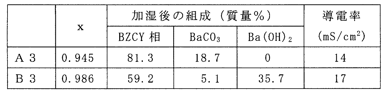
- Example 3 Except using proton conductor Ba 0.945 Zr 0.700 Ce 0.100 Yb 0.200 O 2.900 (a3) instead of the proton conductor (a1), the same procedure as in Example 1, the cell structure The body was produced and the fuel cell was produced. Evaluation similar to Example 1 was performed using the obtained proton conductor and cell structure.
- the proton conductor (a3) was synthesized by the following procedure. Barium carbonate, zirconium oxide, cerium oxide, and ytterbium oxide were mixed in a ball mill at a molar ratio such that the ratio of Ba, Zr, Ce, and Yb was the above formula. The mixture was uniaxially molded to obtain pellets, and the above proton conductor (a3) was synthesized by firing at 1300 ° C. for 10 hours.
- Comparative Example 3 Except using proton conductor Ba 0.986 Zr 0.700 Ce 0.100 Yb 0.200 O 2.900 (b3) in place of the proton conductor (a1), the same procedure as in Example 1, the cell structure The body was produced and the fuel cell was produced. The proton conductor (b3) was synthesized in the same manner as in Example 3 except that the amount of barium carbonate was adjusted. Evaluation similar to Example 1 was performed using the obtained proton conductor and cell structure. The results of Example 3 (A3) and Comparative Example 3 (B3) are shown in Table 2.
- Example 4 Except using proton conductor Ba 0.951 Zr 0.800 Yb 0.200 O 2.900 (a4) in place of the proton conductor (a1), the same procedure as in Example 1, to prepare a cell structure A fuel cell was prepared. Evaluation similar to Example 1 was performed using the obtained proton conductor and cell structure.
- the proton conductor (a4) was synthesized by the following procedure. Barium carbonate, zirconium oxide, and ytterbium oxide were mixed in a ball mill at a molar ratio such that the ratio of Ba, Zr, and Yb was the above formula. The mixture was uniaxially molded to obtain pellets, and the above proton conductor (a4) was synthesized by firing at 1300 ° C. for 10 hours.
- Comparative Example 4 A cell structure was fabricated in the same manner as in Example 1 except that the proton conductor Ba 0.985 Zr 0.800 Yb 0.200 O 2.900 (b4) was used instead of the proton conductor (a1). A fuel cell was prepared. The proton conductor (b4) was synthesized in the same manner as in Example 4 except that the amount of barium carbonate was adjusted. Evaluation similar to Example 1 was performed using the obtained proton conductor and cell structure. The results of Example 4 (A4) and Comparative Example 4 (B4) are shown in Table 3.
- Example 5 (1) Production of Cell Structure and Fuel Cell
- the electrolyte paste prepared in Comparative Example 2 (using proton conductor (b2)) was applied to one main surface of the disk-shaped pellet. It was applied to form a coating film. The pellet on which the coating film was formed was subjected to binder removal treatment by heating at 750 ° C. for 10 hours.
- the electrolyte paste prepared in Example 1 (use of proton conductor (a1)) was applied to the surface of the coating film subjected to the binder removal treatment, and further the binder removal treatment was performed by heating at 750 ° C. for 10 hours.
- the obtained pellets were calcined by heating at 1400 ° C. for 10 hours. In this way, an electrolyte layer-anode assembly in which a solid electrolyte layer was integrally formed on one main surface of the anode was obtained.
- Example 5 Evaluation The cell structure obtained in (1) above was measured at 600 ° C. while changing the current density, and the maximum value of the output density was determined. The result was 312 mW / cm 2 . . In the evaluation of power generation performance, the anode side of the cell structure was exposed to a humidified hydrogen atmosphere, and the cathode side was exposed to an air atmosphere. Moreover, when the power density was evaluated similarly to the above using the cell structure obtained in Comparative Example 1, it was 344 mW / cm 2 . Thus, in Example 5, the high output equivalent to the comparative example 1 was obtained.
- the solid electrolyte layer according to the embodiment of the present invention has excellent moisture resistance and high durability, it is suitable for application to a fuel cell (PCFC) or a cell structure thereof.
- Cell structure 2 Cathode 3: Anode 4: Solid electrolyte layer 5: Electrolyte layer-electrode assembly 10: Fuel cell 21, 51: Current collector 22, 52: Separator 23: Fuel flow path 53: Oxidant flow Road
Abstract
Description
BaxZryCezM1-(y+z)O3-δ
(ただし、元素Mは、Y、Yb、Er、Ho、Tm、Gd、およびScからなる群より選択される少なくとも一種であり、0.85≦x<0.98、0.70≦y+z<1.00、比y/zは0.5/0.5~1/0であり、δは酸素欠損量である)
で表されるプロトン伝導体を含む、燃料電池用固体電解質層に関する。
アノードと、
前記カソードおよび前記アノードの間に介在し、プロトン伝導性を有する固体電解質層と、を備え、
前記固体電解質層は、プロトン伝導体を含み、
前記プロトン伝導体は、ペロブスカイト型構造を有し、かつ下記式(1):
BaxZryCezM1-(y+z)O3-δ
(ただし、元素Mは、Y、Yb、Er、Ho、Tm、Gd、およびScからなる群より選択される少なくとも一種であり、0.85≦x<0.98、0.70≦y+z<1.00、比y/zは0.5/0.5~1/0であり、δは酸素欠損量である)
で表される、セル構造体に関する。
前記カソードに酸化剤を供給するための酸化剤流路、および、前記アノードに燃料を供給するための燃料流路を有する、燃料電池に関する。
BaxZryCezM1-(y+z)O3-δ
(ただし、元素Mは、Y、Yb、Er、Ho、Tm、Gd、およびScからなる群より選択される少なくとも一種であり、0.85≦x<0.98、0.70≦y+z<1.00、比y/zは0.5/0.5~1/0であり、δは酸素欠損量である)
で表されるプロトン伝導体に関する。
最初に、本発明の実施形態の内容を列記して説明する。
本発明の一実施形態に係る燃料電池用固体電解質層は、(1)ペロブスカイト型構造を有し、かつ下記式(1):
BaxZryCezM1-(y+z)O3-δ
(ただし、元素Mは、イットリウム(Y)、イッテルビウム(Yb)、エルビウム(Er)、ホルミウム(Ho)、ツリウム(Tm)、ガドリニウム(Gd)、およびスカンジウム(Sc)からなる群より選択される少なくとも一種であり、0.85≦x<0.98、0.70≦y+z<1.00、比y/zは0.5/0.5~1/0であり、δは酸素欠損量である)
で表されるプロトン伝導体を含む。
セル構造体において、固体電解質層は、プロトン伝導体を含み、プロトン伝導体は、ペロブスカイト型構造を有し、かつ上記式(1)で表される。
(4)本発明の一実施形態に係るプロトン伝導体は、ペロブスカイト型構造を有し、かつ上記式(1)で表される。
また、高いプロトン伝導性を確保し易いため、高い出力を維持することができる。
本発明の実施形態の具体例を、適宜図面を参照しつつ以下に説明する。なお、本発明はこれらの例示に限定されるものではなく、請求の範囲によって示され、請求の範囲と均等の意味および範囲内での全ての変更が含まれることが意図される。
プロトン伝導体は、ペロブスカイト型構造(Perovskite structure、ABO3)を有し、かつ上記式(1)で表される。式(1)の化合物のAサイトにはBaが入り、Bサイトには、ZrおよびCeが入る。Bサイトの一部は、ZrおよびCe以外の元素M(ドーパント)で置換されており、高いプロトン伝導性を確保することができる。
式(1)の化合物において、酸素欠損量δは、元素Mの量に応じて決定でき、例えば、0≦δ≦0.15である。
固体電解質層は、上記のプロトン伝導体を含む。固体電解質層は、上記式(1)の化合物以外の成分を含み得るが、高い耐湿性およびプロトン伝導性を確保し易い観点から、その含有量は少ないことが好ましい。例えば、固体電解質層の50質量%以上または70質量%以上が、式(1)の化合物であることが好ましく、固体電解質層全体の平均的組成が式(1)の組成であってもよい。式(1)の化合物以外の成分としては特に限定されず、固体電解質として公知の化合物(プロトン伝導性を有さない化合物を含む)を挙げることができる。
本発明の一実施形態に係るセル構造体の断面模式図を図1に示す。
セル構造体1は、カソード2と、アノード3と、これらの間に介在する固体電解質層4とを含む。固体電解質層4としては上述の固体電解質層が使用される。図示例では、アノード3と固体電解質層4とは一体化され、電解質層-電極接合体5を形成している。
カソードは、酸素分子を吸着し、解離させてイオン化することができる多孔質の構造を有している。カソード2では、固体電解質層4を介して伝導されたプロトンと、酸化物イオンとの反応(酸素の還元反応)が生じている。酸化物イオンは、酸化剤流路から導入された酸化剤(酸素)が解離することにより生成する。
なお、これらのペロブスカイト型酸化物において、酸素欠損量δは、0≦δ≦0.15であってもよい。
プロトンと酸化物イオンとの反応を促進させる観点から、カソード2は、Pt等の触媒を含んでいても良い。触媒を含む場合、カソード2は、触媒と上記材料とを混合して、焼結することにより形成することができる。
カソード2の厚みは、特に限定されないが、5μm~40μm程度であれば良い。
アノード4は、多孔質の構造を有している。アノード4では、後述する流路から導入される水素などの燃料を酸化して、プロトンと電子とを放出する反応(燃料の酸化反応)が行われる。
一方、アンモニアの分解により同時に生成したN2は、排気ガスとして後述する燃料ガス出口から排出される。アノードには、上記ガスを分解する機能を有する触媒を含ませてもよい。アンモニア等のガスを分解する機能を有する触媒としては、Fe、Co、Ti、Mo、W、Mn、RuおよびCuよりなる群から選択される少なくとも1種の触媒成分を含む化合物が挙げられる。
図2は、図1のセル構造体を含む燃料電池(固体酸化物型燃料電池)を模式的に示す断面図である。
燃料電池10は、セル構造体1と、セル構造体1のカソード2に酸化剤を供給するための酸化剤流路23が形成されたセパレータ22と、アノード3に燃料を供給するための燃料流路53が形成されたセパレータ52とを含む。燃料電池10において、セル構造体1は、カソード側セパレータ22と、アノード側セパレータ52との間に挟持されている。
カソード側セパレータ22の酸化剤流路23は、セル構造体1のカソード2に対向するように配置され、アノード側セパレータ52の燃料流路53は、アノード3に対向するように配置されている。
複数のセル構造体が積層されて、燃料電池が構成される場合には、例えば、セル構造体1と、カソード側セパレータ22と、アノード側セパレータ52とが、一単位として積層される。複数のセル構造体1は、例えば、両面にガス流路(酸化剤流路および燃料流路)を備えるセパレータにより、直列に接続されていてもよい。
カソード側集電体およびアノード側集電体に用いられる構造体としては、例えば、銀、銀合金、ニッケル、ニッケル合金等を含む金属多孔体、金属メッシュ、パンチングメタル、エキスパンドメタル等が挙げられる。なかでも、軽量性や通気性の点で、金属多孔体が好ましい。特に、三次元網目状の構造を有する金属多孔体が好ましい。三次元網目状の構造とは、金属多孔体を構成する棒状や繊維状の金属が相互に三次元的に繋がり合い、ネットワークを形成している構造を指す。例えば、スポンジ状の構造や不織布状の構造が挙げられる。
燃料電池は、上記のセル構造体を用いる以外は、公知の方法により製造できる。
(1)プロトン伝導体Ba0.892Zr0.800Y0.200O2.900(a1)の合成
炭酸バリウムと、酸化ジルコニウムと、酸化イットリウムとを、Baと、Zrと、Yとの比率が上記式となるようなモル比でボールミルに入れて混合した。混合物を一軸成形してペレットを得、1300℃で10時間焼成することにより、上記のプロトン伝導体(a1)を合成した。
上記(1)で得られたプロトン伝導体(a1)と、NiOとを、バインダ(ポリビニルアルコール)、界面活性剤(ポリカルボン酸型界面活性剤)、および適量のエタノールとともに、ボールミルで混合し、造粒した。このとき、プロトン伝導体とNiOとは体積比40:60で混合した。バインダおよび添加剤の量は、プロトン伝導体およびNiOの総量100質量部に対して、それぞれ、10質量部および0.5質量部とした。得られた造粒物を一軸成形することにより、円盤状のペレット(直径20mm)を形成し、1000℃で仮焼成した。
LSCF(La0.6Sr0.4Fe0.8Co0.2O3-δ(δ≒0.1))の粉末と界面活性剤(ポリカルボン酸型界面活性剤)と適量の溶媒(トルエンおよびイソプロパノール)とを含むカソード用ペーストを調製した。上記(2)で得られた接合体の固体電解質層の表面に、カソード用ペーストを塗布し、1000℃で2時間加熱することによりカソード(厚み10μm)を形成した。このようにしてセル構造体を形成した。
セル構造体において、固体電解質層の厚み方向の断面の任意の5箇所について元素の比率をEDXにより測定し、固体電解質層全体の平均的な組成がBa0.892Zr0.800Y0.200O2.900であることを確認した。
上記(3)で得られたセル構造体のカソードおよびアノードのそれぞれの表面に、白金ペーストを塗布し、白金メッシュを取り付けることにより、集電体を形成した。さらに、カソード側の集電体の上に、酸化剤流路を有するステンレス鋼製のカソード側セパレータを積層し、アノード側集電体の上に、燃料流路を有するステンレス鋼製のアノード側セパレータを積層して、図2に示す燃料電池を製作した。
得られたプロトン伝導体の粉末またはこの粉末から作製した焼結体ペレットを用いて、下記の手順で、耐湿性およびプロトン伝導性を評価した。
(a)耐湿性
プロトン伝導体の粉末を、相対湿度100%および温度100℃の条件で、100時間静置した。次いで、X線回折(XRD:X-ray Diffraction)の参照強度比(RIR:Reference Intensity Ratio)法により、粉末を定量分析した。このようにして、加湿後のプロトン伝導体の組成を評価した。
プロトン伝導体の粉末にバインダ(ポリビニルアルコール)を加え、ジルコニア乳鉢にて10分間混合した。バインダの量は、プロトン伝導体100質量部に対して、0.15質量部とした。得られた造粒物を一軸成形することにより、円盤状のペレット(直径20mm)を形成した。さらにペレットに対し2トン/cm2での静水圧プレスを行い、成形体密度を上昇させた。このペレットを、750℃で10時間加熱することにより脱バインダ処理を行った。次いで、得られたペレットを、1600℃で24時間加熱することにより本焼成した。なお、ペレットの加熱は、プロトン伝導体の粉末中に埋めた状態で行った。
サンプルの抵抗値を、加湿水素雰囲気下で交流インピーダンス法により測定し、測定値から、サンプルの導電率を算出した。この導電率を、プロトン伝導性の指標とした。
プロトン伝導体(a1)に代えてプロトン伝導体Ba0.957Zr0.800Y0.200O2.900(a2)を用いる以外は、実施例1と同様にして、セル構造体を作製し、燃料電池を作製した。プロトン伝導体(a2)は、炭酸バリウムの量を調節した以外は、実施例1の(1)と同様にして合成した。
得られたプロトン伝導体およびセル構造体を用いて、実施例1と同様の評価を行った。
プロトン伝導体(a1)に代えてプロトン伝導体Ba0.980Zr0.800Y0.200O2.900(b1)を用いる以外は、実施例1と同様にして、セル構造体を作製し、燃料電池を作製した。プロトン伝導体(b1)は、炭酸バリウムの量を調節した以外は、実施例1の(1)と同様にして合成した。
得られたプロトン伝導体およびセル構造体を用いて、実施例1と同様の評価を行った。
プロトン伝導体(a1)に代えてプロトン伝導体Ba1.000Zr0.800Y0.200O2.900(b2)を用いる以外は、実施例1と同様にして、セル構造体を作製し、燃料電池を作製した。プロトン伝導体(b2)は、炭酸バリウムの量を調節した以外は、実施例1の(1)と同様にして合成した。
得られたプロトン伝導体およびセル構造体を用いて、実施例1と同様の評価を行った。
実施例1~2および比較例1~2の結果を表1に示す。実施例1および2がA1およびA2であり、比較例1および2がB1およびB2である。

プロトン伝導体(a1)に代えてプロトン伝導体Ba0.945Zr0.700Ce0.100Yb0.200O2.900(a3)を用いる以外は、実施例1と同様にして、セル構造体を作製し、燃料電池を作製した。得られたプロトン伝導体およびセル構造体を用いて、実施例1と同様の評価を行った。
炭酸バリウムと、酸化ジルコニウムと、酸化セリウムと、酸化イッテルビウムとを、Baと、Zrと、Ceと、Ybとの比率が上記式となるようなモル比でボールミルに入れて混合した。混合物を一軸成形してペレットを得、1300℃で10時間焼成することにより、上記のプロトン伝導体(a3)を合成した。
プロトン伝導体(a1)に代えてプロトン伝導体Ba0.986Zr0.700Ce0.100Yb0.200O2.900(b3)を用いる以外は、実施例1と同様にして、セル構造体を作製し、燃料電池を作製した。プロトン伝導体(b3)は、炭酸バリウムの量を調節した以外は、実施例3と同様にして合成した。
得られたプロトン伝導体およびセル構造体を用いて、実施例1と同様の評価を行った。
実施例3(A3)および比較例3(B3)の結果を表2に示す。
プロトン伝導体(a1)に代えてプロトン伝導体Ba0.951Zr0.800Yb0.200O2.900(a4)を用いる以外は、実施例1と同様にして、セル構造体を作製し、燃料電池を作製した。得られたプロトン伝導体およびセル構造体を用いて、実施例1と同様の評価を行った。
炭酸バリウムと、酸化ジルコニウムと、酸化イッテルビウムとを、Baと、Zrと、Ybとの比率が上記式となるようなモル比でボールミルに入れて混合した。混合物を一軸成形してペレットを得、1300℃で10時間焼成することにより、上記のプロトン伝導体(a4)を合成した。
プロトン伝導体(a1)に代えてプロトン伝導体Ba0.985Zr0.800Yb0.200O2.900(b4)を用いる以外は、実施例1と同様にして、セル構造体を作製し、燃料電池を作製した。プロトン伝導体(b4)は、炭酸バリウムの量を調節した以外は、実施例4と同様にして合成した。
得られたプロトン伝導体およびセル構造体を用いて、実施例1と同様の評価を行った。
実施例4(A4)および比較例4(B4)の結果を表3に示す。
(1)セル構造体および燃料電池の作製
実施例1の(2)において、比較例2で調製した電解質ペースト(プロトン伝導体(b2)を使用)を、円盤状のペレットの一方の主面に塗布して塗膜を形成した。塗膜が形成されたペレットを750℃で10時間加熱することにより脱バインダ処理した。次いで、脱バインダ処理した塗膜の表面に、実施例1で調製した電解質ペースト(プロトン伝導体(a1)使用)を塗布し、さらに750℃で10時間加熱することにより脱バインダ処理した。得られたペレットを、1400℃で10時間加熱することにより本焼成した。このようにして、アノードの一方の主面に固体電解質層が一体に形成された電解質層-アノード接合体を得た。
固体電解質層とアノードとの界面から0.25Tの位置におけるBaの比x1、および固体電解質層の表面から0.25Tの位置におけるBaの比率x2を、それぞれ、EPMAにより測定した。その結果、x1は、1.000であり、x2は0.892であった。
得られた接合体を用いる以外は実施例1と同様にしてセル構造体および燃料電池を作製した。
上記(1)で得られたセル構造体を、600℃で、電流密度を変化させながら出力密度を測定し、出力密度の最大値を求めたところ、312mW/cm2であった。なお、発電性能の評価の際、セル構造体のアノード側は加湿水素雰囲気に晒し、カソード側は大気雰囲気に晒した状態とした。また、比較例1で得られたセル構造体を用いて、上記と同様に、出力密度を評価したところ、344mW/cm2であった。このように、実施例5では、比較例1に匹敵する高い出力が得られた。
2:カソード
3:アノード
4:固体電解質層
5:電解質層-電極接合体
10:燃料電池
21、51:集電体
22、52:セパレータ
23:燃料流路
53:酸化剤流路
Claims (9)
- ペロブスカイト型構造を有し、かつ下記式(1):
BaxZryCezM1-(y+z)O3-δ
(ただし、元素Mは、Y、Yb、Er、Ho、Tm、Gd、およびScからなる群より選択される少なくとも一種であり、0.85≦x<0.98、0.70≦y+z<1.00、比y/zは0.5/0.5~1/0であり、δは酸素欠損量である)
で表されるプロトン伝導体を含む、燃料電池用固体電解質層。 - 0.85≦x≦0.96である、請求項1に記載の燃料電池用固体電解質層。
- 0.75≦y+z≦0.90である、請求項1または請求項2に記載の燃料電池用固体電解質層。
- 前記元素Mは、YおよびYbからなる群より選択される少なくとも一種である、請求項1~請求項3のいずれか1項に記載の燃料電池用固体電解質層。
- 前記固体電解質層の厚みをTとするとき、
前記固体電解質層の一方の表面から0.25Tの位置におけるBaの比率x1と、前記固体電解質層の他方の表面から0.25Tの位置におけるBaの比率x2とが、x1>x2を満たし、
前記他方の表面を、燃料電池のカソードと接触させる、請求項1~請求項4のいずれか1項に記載の燃料電池用固体電解質層。 - ZrとCeとの比y/zは、0.5/0.5~0.9/0.1である、請求項1~請求項5のいずれか1項に記載の燃料電池用固体電解質層。
- カソードと、
アノードと、
前記カソードおよび前記アノードの間に介在し、プロトン伝導性を有する固体電解質層と、を備え、
前記固体電解質層は、プロトン伝導体を含み、
前記プロトン伝導体は、ペロブスカイト型構造を有し、かつ下記式(1):
BaxZryCezM1-(y+z)O3-δ
(ただし、元素Mは、Y、Yb、Er、Ho、Tm、Gd、およびScからなる群より選択される少なくとも一種であり、0.85≦x<0.98、0.70≦y+z<1.00、比y/zは0.5/0.5~1/0であり、δは酸素欠損量である)
で表される、セル構造体。 - 請求項7に記載のセル構造体を備え、
前記カソードに酸化剤を供給するための酸化剤流路、および、前記アノードに燃料を供給するための燃料流路を有する、燃料電池。 - ペロブスカイト型構造を有し、かつ下記式(1):
BaxZryCezM1-(y+z)O3-δ
(ただし、元素Mは、Y、Yb、Er、Ho、Tm、Gd、およびScからなる群より選択される少なくとも一種であり、0.85≦x<0.98、0.70≦y+z<1.00、比y/zは0.5/0.5~1/0であり、δは酸素欠損量である)
で表されるプロトン伝導体。
Priority Applications (5)
| Application Number | Priority Date | Filing Date | Title |
|---|---|---|---|
| JP2017509141A JP6601488B2 (ja) | 2015-03-30 | 2015-08-25 | プロトン伝導体、燃料電池用固体電解質層、セル構造体およびそれを備える燃料電池 |
| CN201580077101.1A CN107406332B (zh) | 2015-03-30 | 2015-08-25 | 质子导体、燃料电池用固体电解质层、电池结构体以及包括电池结构体的燃料电池 |
| KR1020177023775A KR20170132140A (ko) | 2015-03-30 | 2015-08-25 | 프로톤 전도체, 연료 전지용 고체 전해질층, 셀 구조체 및 그것을 구비하는 연료 전지 |
| US15/553,237 US20180037508A1 (en) | 2015-03-30 | 2015-08-25 | Proton conductor, solid electrolyte layer for fuel cell, cell structure, and fuel cell including the same |
| EP15887708.4A EP3279987B1 (en) | 2015-03-30 | 2015-08-25 | Proton conductor, fuel-cell solid-electrolyte layer, cell structure, and fuel cell provided with same |
Applications Claiming Priority (2)
| Application Number | Priority Date | Filing Date | Title |
|---|---|---|---|
| JP2015068668 | 2015-03-30 | ||
| JP2015-068668 | 2015-03-30 |
Publications (1)
| Publication Number | Publication Date |
|---|---|
| WO2016157566A1 true WO2016157566A1 (ja) | 2016-10-06 |
Family
ID=57005738
Family Applications (1)
| Application Number | Title | Priority Date | Filing Date |
|---|---|---|---|
| PCT/JP2015/073879 WO2016157566A1 (ja) | 2015-03-30 | 2015-08-25 | プロトン伝導体、燃料電池用固体電解質層、セル構造体およびそれを備える燃料電池 |
Country Status (6)
| Country | Link |
|---|---|
| US (1) | US20180037508A1 (ja) |
| EP (1) | EP3279987B1 (ja) |
| JP (1) | JP6601488B2 (ja) |
| KR (1) | KR20170132140A (ja) |
| CN (1) | CN107406332B (ja) |
| WO (1) | WO2016157566A1 (ja) |
Cited By (12)
| Publication number | Priority date | Publication date | Assignee | Title |
|---|---|---|---|---|
| CN106602136A (zh) * | 2016-12-22 | 2017-04-26 | 中国矿业大学 | 一种锆酸钡基电解质材料体系及其制备方法 |
| CN108123153A (zh) * | 2016-11-25 | 2018-06-05 | 中国科学院大连化学物理研究所 | 一种质子型固体氧化物燃料电池及其制备方法 |
| JP2018139183A (ja) * | 2017-02-24 | 2018-09-06 | 住友電気工業株式会社 | 固体電解質部材、固体酸化物型燃料電池、水電解装置、水素ポンプ及び固体電解質部材の製造方法 |
| JP2018139182A (ja) * | 2017-02-24 | 2018-09-06 | 住友電気工業株式会社 | 固体電解質部材、固体酸化物型燃料電池、水電解装置、水素ポンプ及び固体電解質部材の製造方法 |
| JP2019021578A (ja) * | 2017-07-20 | 2019-02-07 | 東京瓦斯株式会社 | 燃料電池システム |
| JP2019042673A (ja) * | 2017-09-01 | 2019-03-22 | 東京瓦斯株式会社 | 触媒組成物、水素製造装置、および、水素製造方法 |
| WO2019107194A1 (ja) * | 2017-11-29 | 2019-06-06 | 国立大学法人京都大学 | プロトン伝導体、プロトン伝導型セル構造体、水蒸気電解セルおよび水素極-固体電解質層複合体の製造方法 |
| JPWO2018159584A1 (ja) * | 2017-02-28 | 2020-01-09 | 国立研究開発法人産業技術総合研究所 | プロトン伝導性電解質 |
| JP2020017425A (ja) * | 2018-07-26 | 2020-01-30 | 東京瓦斯株式会社 | 燃料電池および燃料電池の製造方法 |
| WO2020218150A1 (ja) * | 2019-04-23 | 2020-10-29 | 堺化学工業株式会社 | イッテルビウム添加ジルコン酸バリウム粒子とその製造方法 |
| WO2021256221A1 (ja) * | 2020-06-18 | 2021-12-23 | 住友電気工業株式会社 | プロトン伝導型セル構造体、プロトン伝導体、電気化学デバイス、及びプロトン伝導体の製造方法 |
| JP7336702B2 (ja) | 2018-10-18 | 2023-09-01 | パナソニックIpマネジメント株式会社 | 膜電極接合体および燃料電池 |
Families Citing this family (8)
| Publication number | Priority date | Publication date | Assignee | Title |
|---|---|---|---|---|
| CN108370041A (zh) * | 2015-12-18 | 2018-08-03 | 住友电气工业株式会社 | 质子导体、电池结构体、质子导体和电池结构体的制造方法、燃料电池以及水电解装置 |
| US20210066728A1 (en) * | 2018-03-06 | 2021-03-04 | Sumitomo Electric Industries, Ltd. | Cell structure |
| CN111801827B (zh) * | 2018-03-06 | 2023-08-18 | 住友电气工业株式会社 | 电解质层-阳极复合部件以及电池结构体 |
| CN109023411B (zh) * | 2018-07-11 | 2020-09-18 | 中国科学院上海高等研究院 | 用于电解水的消除内短路的氧化铈基固体电池及其制备方法和用途 |
| JP6773240B2 (ja) * | 2018-08-30 | 2020-10-21 | 堺化学工業株式会社 | 固体酸化物形燃料電池用電解質材料とその前駆体の製造方法 |
| JPWO2020217743A1 (ja) * | 2019-04-26 | 2020-10-29 | ||
| EP3960907A4 (en) * | 2019-04-26 | 2022-06-15 | Panasonic Intellectual Property Management Co., Ltd. | MEMBRANE ELECTRODE, ELECTROCHEMICAL DEVICE AND ELECTROCHEMICAL SYSTEM ASSEMBLY |
| CN113149092B (zh) * | 2021-03-10 | 2022-07-29 | 南京工业大学 | 一种b位掺杂的质子导体燃料电池的电解质材料、制备方法以及直接氨燃料电池中的应用 |
Citations (3)
| Publication number | Priority date | Publication date | Assignee | Title |
|---|---|---|---|---|
| JP2007197315A (ja) * | 1999-02-17 | 2007-08-09 | Matsushita Electric Ind Co Ltd | 混合イオン伝導体およびこれを用いたデバイス |
| WO2015008407A1 (ja) * | 2013-07-16 | 2015-01-22 | パナソニックIpマネジメント株式会社 | プロトン伝導体 |
| JP2015046251A (ja) * | 2013-08-27 | 2015-03-12 | 住友電気工業株式会社 | 燃料極用電極材料、固体電解質−電極積層体、固体電解質−電極積層体の製造方法及び燃料電池 |
Family Cites Families (11)
| Publication number | Priority date | Publication date | Assignee | Title |
|---|---|---|---|---|
| US5725965A (en) * | 1995-04-25 | 1998-03-10 | Gas Research Institute | Stable high conductivity functionally gradient compositionally layered solid state electrolytes and membranes |
| CA2298850A1 (en) * | 1999-02-17 | 2000-08-17 | Matsushita Electric Industrial Co., Ltd. | Mixed ionic conductor and device using the same |
| US20040058227A1 (en) * | 2002-07-09 | 2004-03-25 | Matsushita Electric Industrial Co., Ltd. | Electrolyte membrane-electrode assembly for a fuel cell, fuel cell using the same and method of making the same |
| US7745063B2 (en) * | 2004-04-27 | 2010-06-29 | Panasonic Corporation | Fuel cell stack |
| US7625653B2 (en) * | 2005-03-15 | 2009-12-01 | Panasonic Corporation | Ionic conductor |
| CN100537470C (zh) * | 2005-03-15 | 2009-09-09 | 松下电器产业株式会社 | 离子导体 |
| CN103208634B (zh) * | 2013-03-25 | 2016-04-27 | 北京科技大学 | 用于中低温质子传输固体氧化物燃料电池的复合阴极材料 |
| CN103224394A (zh) * | 2013-04-19 | 2013-07-31 | 天津大学 | 碳酸锂改性铈锆酸钡质子导体材料及其制备方法 |
| US9437343B2 (en) * | 2013-07-16 | 2016-09-06 | Panasonic Intellectual Property Management Co., Ltd. | Proton conductor |
| CN103531833A (zh) * | 2013-10-22 | 2014-01-22 | 天津大学 | 碳酸锂/钇掺杂铈锆酸钡复相结构质子导体材料 |
| WO2015114684A1 (ja) * | 2014-01-31 | 2015-08-06 | パナソニックIpマネジメント株式会社 | プロトン伝導体 |
-
2015
- 2015-08-25 JP JP2017509141A patent/JP6601488B2/ja active Active
- 2015-08-25 EP EP15887708.4A patent/EP3279987B1/en active Active
- 2015-08-25 US US15/553,237 patent/US20180037508A1/en not_active Abandoned
- 2015-08-25 KR KR1020177023775A patent/KR20170132140A/ko unknown
- 2015-08-25 WO PCT/JP2015/073879 patent/WO2016157566A1/ja active Application Filing
- 2015-08-25 CN CN201580077101.1A patent/CN107406332B/zh active Active
Patent Citations (3)
| Publication number | Priority date | Publication date | Assignee | Title |
|---|---|---|---|---|
| JP2007197315A (ja) * | 1999-02-17 | 2007-08-09 | Matsushita Electric Ind Co Ltd | 混合イオン伝導体およびこれを用いたデバイス |
| WO2015008407A1 (ja) * | 2013-07-16 | 2015-01-22 | パナソニックIpマネジメント株式会社 | プロトン伝導体 |
| JP2015046251A (ja) * | 2013-08-27 | 2015-03-12 | 住友電気工業株式会社 | 燃料極用電極材料、固体電解質−電極積層体、固体電解質−電極積層体の製造方法及び燃料電池 |
Cited By (19)
| Publication number | Priority date | Publication date | Assignee | Title |
|---|---|---|---|---|
| CN108123153A (zh) * | 2016-11-25 | 2018-06-05 | 中国科学院大连化学物理研究所 | 一种质子型固体氧化物燃料电池及其制备方法 |
| CN106602136A (zh) * | 2016-12-22 | 2017-04-26 | 中国矿业大学 | 一种锆酸钡基电解质材料体系及其制备方法 |
| JP2018139183A (ja) * | 2017-02-24 | 2018-09-06 | 住友電気工業株式会社 | 固体電解質部材、固体酸化物型燃料電池、水電解装置、水素ポンプ及び固体電解質部材の製造方法 |
| JP2018139182A (ja) * | 2017-02-24 | 2018-09-06 | 住友電気工業株式会社 | 固体電解質部材、固体酸化物型燃料電池、水電解装置、水素ポンプ及び固体電解質部材の製造方法 |
| JP7021787B2 (ja) | 2017-02-28 | 2022-02-17 | 国立研究開発法人産業技術総合研究所 | プロトン伝導性電解質 |
| JPWO2018159584A1 (ja) * | 2017-02-28 | 2020-01-09 | 国立研究開発法人産業技術総合研究所 | プロトン伝導性電解質 |
| JP7029122B2 (ja) | 2017-07-20 | 2022-03-03 | 東京瓦斯株式会社 | 燃料電池システム |
| JP2019021578A (ja) * | 2017-07-20 | 2019-02-07 | 東京瓦斯株式会社 | 燃料電池システム |
| JP2019042673A (ja) * | 2017-09-01 | 2019-03-22 | 東京瓦斯株式会社 | 触媒組成物、水素製造装置、および、水素製造方法 |
| WO2019107194A1 (ja) * | 2017-11-29 | 2019-06-06 | 国立大学法人京都大学 | プロトン伝導体、プロトン伝導型セル構造体、水蒸気電解セルおよび水素極-固体電解質層複合体の製造方法 |
| US11545690B2 (en) | 2017-11-29 | 2023-01-03 | Kyoto University | Proton conductor, proton-conducting cell structure, water vapor electrolysis cell, and method for producing hydrogen electrode-solid electrolyte layer complex |
| JPWO2019107194A1 (ja) * | 2017-11-29 | 2020-12-17 | 国立大学法人京都大学 | プロトン伝導体、プロトン伝導型セル構造体、水蒸気電解セルおよび水素極−固体電解質層複合体の製造方法 |
| JP7225113B2 (ja) | 2017-11-29 | 2023-02-20 | 国立大学法人京都大学 | プロトン伝導体、プロトン伝導型セル構造体、水蒸気電解セルおよび水素極-固体電解質層複合体の製造方法 |
| JP2020017425A (ja) * | 2018-07-26 | 2020-01-30 | 東京瓦斯株式会社 | 燃料電池および燃料電池の製造方法 |
| JP7057731B2 (ja) | 2018-07-26 | 2022-04-20 | 東京瓦斯株式会社 | 燃料電池および燃料電池の製造方法 |
| JP7336702B2 (ja) | 2018-10-18 | 2023-09-01 | パナソニックIpマネジメント株式会社 | 膜電極接合体および燃料電池 |
| JP6787537B1 (ja) * | 2019-04-23 | 2020-11-18 | 堺化学工業株式会社 | イッテルビウム添加ジルコン酸バリウム粒子とその製造方法 |
| WO2020218150A1 (ja) * | 2019-04-23 | 2020-10-29 | 堺化学工業株式会社 | イッテルビウム添加ジルコン酸バリウム粒子とその製造方法 |
| WO2021256221A1 (ja) * | 2020-06-18 | 2021-12-23 | 住友電気工業株式会社 | プロトン伝導型セル構造体、プロトン伝導体、電気化学デバイス、及びプロトン伝導体の製造方法 |
Also Published As
| Publication number | Publication date |
|---|---|
| KR20170132140A (ko) | 2017-12-01 |
| CN107406332B (zh) | 2020-11-03 |
| EP3279987A4 (en) | 2018-04-11 |
| JPWO2016157566A1 (ja) | 2018-02-15 |
| CN107406332A (zh) | 2017-11-28 |
| JP6601488B2 (ja) | 2019-11-06 |
| EP3279987B1 (en) | 2019-11-27 |
| US20180037508A1 (en) | 2018-02-08 |
| EP3279987A1 (en) | 2018-02-07 |
Similar Documents
| Publication | Publication Date | Title |
|---|---|---|
| JP6601488B2 (ja) | プロトン伝導体、燃料電池用固体電解質層、セル構造体およびそれを備える燃料電池 | |
| US10734665B2 (en) | Method for producing cell structure | |
| JP6658754B2 (ja) | 固体酸化物形燃料電池、および電解質層−アノード接合体の製造方法 | |
| JP6398647B2 (ja) | 固体酸化物型燃料電池用アノードの製造方法および燃料電池用電解質層−電極接合体の製造方法 | |
| CN101223656A (zh) | 前体渗透和涂布方法 | |
| JP6642446B2 (ja) | セル構造体、その製造方法、および、燃料電池 | |
| WO2017014069A1 (ja) | 燃料電池用電解質層-アノード複合部材およびその製造方法 | |
| JP6370696B2 (ja) | セル構造体、電解質膜−電極接合体、および、燃料電池 | |
| JP7016615B2 (ja) | プロトン伝導体、固体電解質層、セル構造体、およびそれを備える水蒸気電解セルならびに燃料電池 | |
| WO2020004333A1 (ja) | 固体酸化物形セル用電極及びそれを用いた固体酸化物形セル | |
| KR102111859B1 (ko) | 고체산화물 연료 전지 및 이를 포함하는 전지 모듈 | |
| JP7107875B2 (ja) | 燃料極-固体電解質層複合体の製造方法 | |
| JP7114555B2 (ja) | 水蒸気電解用電極 | |
| JP7243709B2 (ja) | 燃料電池用電解質層-アノード複合部材、セル構造体および燃料電池、ならびに複合部材の製造方法 | |
| JP2015185246A (ja) | アノード支持基板及びアノード支持型セル | |
| JP7136185B2 (ja) | セル構造体 | |
| WO2021256221A1 (ja) | プロトン伝導型セル構造体、プロトン伝導体、電気化学デバイス、及びプロトン伝導体の製造方法 | |
| WO2020261935A1 (ja) | 燃料極-固体電解質層複合体、燃料極-固体電解質層複合部材、燃料電池、および、燃料電池の製造方法 | |
| KR20200105173A (ko) | 고체산화물 연료전지용 공기극, 이를 포함하는 고체산화물 연료 전지, 이를 포함하는 전지모듈 및 고체산화물 연료전지의 제조방법 |
Legal Events
| Date | Code | Title | Description |
|---|---|---|---|
| 121 | Ep: the epo has been informed by wipo that ep was designated in this application |
Ref document number: 15887708 Country of ref document: EP Kind code of ref document: A1 |
|
| REEP | Request for entry into the european phase |
Ref document number: 2015887708 Country of ref document: EP |
|
| WWE | Wipo information: entry into national phase |
Ref document number: 15553237 Country of ref document: US |
|
| ENP | Entry into the national phase |
Ref document number: 20177023775 Country of ref document: KR Kind code of ref document: A |
|
| ENP | Entry into the national phase |
Ref document number: 2017509141 Country of ref document: JP Kind code of ref document: A |
|
| NENP | Non-entry into the national phase |
Ref country code: DE |