WO2016157357A1 - フラックス塗布装置及びはんだ - Google Patents
フラックス塗布装置及びはんだ Download PDFInfo
- Publication number
- WO2016157357A1 WO2016157357A1 PCT/JP2015/059899 JP2015059899W WO2016157357A1 WO 2016157357 A1 WO2016157357 A1 WO 2016157357A1 JP 2015059899 W JP2015059899 W JP 2015059899W WO 2016157357 A1 WO2016157357 A1 WO 2016157357A1
- Authority
- WO
- WIPO (PCT)
- Prior art keywords
- solder
- flux
- roller
- speed
- conveying
- Prior art date
Links
Images


Classifications
-
- B—PERFORMING OPERATIONS; TRANSPORTING
- B23—MACHINE TOOLS; METAL-WORKING NOT OTHERWISE PROVIDED FOR
- B23K—SOLDERING OR UNSOLDERING; WELDING; CLADDING OR PLATING BY SOLDERING OR WELDING; CUTTING BY APPLYING HEAT LOCALLY, e.g. FLAME CUTTING; WORKING BY LASER BEAM
- B23K35/00—Rods, electrodes, materials, or media, for use in soldering, welding, or cutting
- B23K35/02—Rods, electrodes, materials, or media, for use in soldering, welding, or cutting characterised by mechanical features, e.g. shape
- B23K35/0222—Rods, electrodes, materials, or media, for use in soldering, welding, or cutting characterised by mechanical features, e.g. shape for use in soldering, brazing
- B23K35/0233—Sheets, foils
- B23K35/0238—Sheets, foils layered
-
- B—PERFORMING OPERATIONS; TRANSPORTING
- B05—SPRAYING OR ATOMISING IN GENERAL; APPLYING FLUENT MATERIALS TO SURFACES, IN GENERAL
- B05C—APPARATUS FOR APPLYING FLUENT MATERIALS TO SURFACES, IN GENERAL
- B05C3/00—Apparatus in which the work is brought into contact with a bulk quantity of liquid or other fluent material
- B05C3/02—Apparatus in which the work is brought into contact with a bulk quantity of liquid or other fluent material the work being immersed in the liquid or other fluent material
- B05C3/12—Apparatus in which the work is brought into contact with a bulk quantity of liquid or other fluent material the work being immersed in the liquid or other fluent material for treating work of indefinite length
- B05C3/125—Apparatus in which the work is brought into contact with a bulk quantity of liquid or other fluent material the work being immersed in the liquid or other fluent material for treating work of indefinite length the work being a web, band, strip or the like
-
- B—PERFORMING OPERATIONS; TRANSPORTING
- B05—SPRAYING OR ATOMISING IN GENERAL; APPLYING FLUENT MATERIALS TO SURFACES, IN GENERAL
- B05C—APPARATUS FOR APPLYING FLUENT MATERIALS TO SURFACES, IN GENERAL
- B05C9/00—Apparatus or plant for applying liquid or other fluent material to surfaces by means not covered by any preceding group, or in which the means of applying the liquid or other fluent material is not important
- B05C9/08—Apparatus or plant for applying liquid or other fluent material to surfaces by means not covered by any preceding group, or in which the means of applying the liquid or other fluent material is not important for applying liquid or other fluent material and performing an auxiliary operation
- B05C9/14—Apparatus or plant for applying liquid or other fluent material to surfaces by means not covered by any preceding group, or in which the means of applying the liquid or other fluent material is not important for applying liquid or other fluent material and performing an auxiliary operation the auxiliary operation involving heating or cooling
-
- B—PERFORMING OPERATIONS; TRANSPORTING
- B23—MACHINE TOOLS; METAL-WORKING NOT OTHERWISE PROVIDED FOR
- B23K—SOLDERING OR UNSOLDERING; WELDING; CLADDING OR PLATING BY SOLDERING OR WELDING; CUTTING BY APPLYING HEAT LOCALLY, e.g. FLAME CUTTING; WORKING BY LASER BEAM
- B23K3/00—Tools, devices, or special appurtenances for soldering, e.g. brazing, or unsoldering, not specially adapted for particular methods
- B23K3/08—Auxiliary devices therefor
- B23K3/082—Flux dispensers; Apparatus for applying flux
-
- B—PERFORMING OPERATIONS; TRANSPORTING
- B23—MACHINE TOOLS; METAL-WORKING NOT OTHERWISE PROVIDED FOR
- B23K—SOLDERING OR UNSOLDERING; WELDING; CLADDING OR PLATING BY SOLDERING OR WELDING; CUTTING BY APPLYING HEAT LOCALLY, e.g. FLAME CUTTING; WORKING BY LASER BEAM
- B23K3/00—Tools, devices, or special appurtenances for soldering, e.g. brazing, or unsoldering, not specially adapted for particular methods
- B23K3/08—Auxiliary devices therefor
- B23K3/085—Cooling, heat sink or heat shielding means
-
- B—PERFORMING OPERATIONS; TRANSPORTING
- B23—MACHINE TOOLS; METAL-WORKING NOT OTHERWISE PROVIDED FOR
- B23K—SOLDERING OR UNSOLDERING; WELDING; CLADDING OR PLATING BY SOLDERING OR WELDING; CUTTING BY APPLYING HEAT LOCALLY, e.g. FLAME CUTTING; WORKING BY LASER BEAM
- B23K35/00—Rods, electrodes, materials, or media, for use in soldering, welding, or cutting
- B23K35/02—Rods, electrodes, materials, or media, for use in soldering, welding, or cutting characterised by mechanical features, e.g. shape
- B23K35/0222—Rods, electrodes, materials, or media, for use in soldering, welding, or cutting characterised by mechanical features, e.g. shape for use in soldering, brazing
- B23K35/0233—Sheets, foils
-
- B—PERFORMING OPERATIONS; TRANSPORTING
- B23—MACHINE TOOLS; METAL-WORKING NOT OTHERWISE PROVIDED FOR
- B23K—SOLDERING OR UNSOLDERING; WELDING; CLADDING OR PLATING BY SOLDERING OR WELDING; CUTTING BY APPLYING HEAT LOCALLY, e.g. FLAME CUTTING; WORKING BY LASER BEAM
- B23K35/00—Rods, electrodes, materials, or media, for use in soldering, welding, or cutting
- B23K35/40—Making wire or rods for soldering or welding
- B23K35/404—Coated rods; Coated electrodes
-
- B—PERFORMING OPERATIONS; TRANSPORTING
- B05—SPRAYING OR ATOMISING IN GENERAL; APPLYING FLUENT MATERIALS TO SURFACES, IN GENERAL
- B05C—APPARATUS FOR APPLYING FLUENT MATERIALS TO SURFACES, IN GENERAL
- B05C9/00—Apparatus or plant for applying liquid or other fluent material to surfaces by means not covered by any preceding group, or in which the means of applying the liquid or other fluent material is not important
- B05C9/08—Apparatus or plant for applying liquid or other fluent material to surfaces by means not covered by any preceding group, or in which the means of applying the liquid or other fluent material is not important for applying liquid or other fluent material and performing an auxiliary operation
- B05C9/12—Apparatus or plant for applying liquid or other fluent material to surfaces by means not covered by any preceding group, or in which the means of applying the liquid or other fluent material is not important for applying liquid or other fluent material and performing an auxiliary operation the auxiliary operation being performed after the application
Definitions
- the present invention relates to a flux application device for applying a flux to the surface of the solder and a solder to which flux is applied using the flux application device.
- the flux used for soldering is applied through a flux application process during soldering.
- the flux chemically removes the metal oxides present on the solder and the metal surface to be soldered, and forms an intermetallic compound between the solder and the metal to be soldered, so that a strong bond can be obtained.
- the flux has the effect of preventing reoxidation due to heating during soldering and reducing the surface tension of the solder to improve wettability.
- a flux-coated preform solder in which a flux is applied to the surface of a solder formed into a long strip has been proposed. Since this flux coat preform solder is coated with a flux in advance, the flux application process at the time of soldering can be eliminated. Further, since the flux coat preform solder has a long strip shape, it can be applied to various mounting processes by processing into a desired shape such as pellets, washers, and disks.
- Patent Document 1 on the premise that flux is applied to the surface of the solder wire immediately before soldering, the solder wire is passed through a bath containing molten flux, and the flux adhering to the solder wire is flux-applied with a die.
- a flux coating apparatus that adjusts the amount and pulls out with a roller is disclosed.
- the conventional flux coating apparatus has the following drawbacks. 1. When the flux coating apparatus is used for a long time, the flux adheres to a member (die) for adjusting the flux coating amount and solidifies, and the flux cannot be coated to a uniform thickness. 2. When it is desired to change the film thickness of the flux applied to the solder, it is necessary to replace the member (die) itself that adjusts the flux application amount.
- the present invention solves such problems, and it is possible to apply the flux to the surface of the solder to a uniform thickness, and to maintain the uniformity even if the flux application apparatus is used for a long period of time. With the goal.
- a flux application apparatus for applying a flux to the surface of solder, a dip coating means for immersing the solder in the flux and applying the flux to the solder surface, and a side where the solder is introduced is upstream, and the solder is discharged.
- a load means that applies a predetermined load to the solder, and a solder that is applied with the flux by the dip coating means and pulled up perpendicular to the liquid level of the flux
- a constant speed conveying means for conveying at a predetermined speed in a state where a load is applied by the loading means, a drying means for drying the solder coated with the flux, a cooling means for cooling the dried solder, and a solder
- a flux application apparatus comprising a conveying speed measuring means for measuring the conveying speed of the solder and a control means for controlling the conveying speed of the solder.
- the constant speed conveying means includes a conveying means, and the conveying means has one or more conveying rollers, the conveying roller has two roller members that sandwich the solder, and the roller member has both the solder.
- the dip coating unit, the drying unit, and the cooling unit are housed in the flux coating chamber, and the flux coating chamber further includes an exhaust unit that exhausts hot air outside the drying unit and in the flux coating chamber. Or the flux application
- the constant-speed conveyance unit includes a winding unit, and further includes an interlayer paper supply unit that supplies an interlayer paper when the solder is wound by the winding unit. 2.
- the flux can be applied to the solder with a uniform thin film thickness. Even when it is desired to change the film thickness of the flux applied to the solder, it is not necessary to change the arrangement of the members or the members themselves. Since this effect can be obtained even if this flux coating apparatus is used for a long period of time, highly reliable flux coating can be performed.
- the flux is applied with a uniform thinness. For this reason, it becomes possible to manufacture a solder having a good solderability and a flux applied to the surface, that is, a flux coat preform solder.
- FIG. 4 is a plan view illustrating a configuration example of a conveyance roller 42.
- FIG. FIG. 10 is a right side view illustrating an operation example of the transport roller.
- 4 is a side view showing a configuration example of a bearing member 47.
- FIG. 4 is a plan view illustrating a configuration example of a conveyance roller 44.
- FIG. 3 is a block diagram illustrating a configuration example of a control system of the flux applying apparatus 100.
- FIG. FIG. 6 is a cross-sectional view showing a configuration example of solder 9.
- FIG. 6 is a process diagram illustrating an example of forming solder 9.
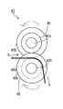
- a flux applying apparatus 100 shown in FIG. 1 is an apparatus that applies a flux 3 having a uniform film thickness to the surface of a solder formed into a long strip having a predetermined width as an example.
- the side in which the solder formed in a long strip shape is fed out (supplied) and put into the flux tank 30, that is, the left side in the figure, is upstream with respect to the solder conveying direction.
- the side discharged from the flux tank 30 and winding the solder that is, the right side is the downstream side. Solder is conveyed from upstream to downstream.
- solder before application of flux 3 will be described as solder 9a and the solder after application of flux 3 will be described as solder 9.
- the flux coating apparatus 100 is configured to wind a solder supply unit 1, a flux coating chamber 2 for coating the solder 9 a with the flux 3 (texture in the drawing), a transport unit 4 for transporting the solder 9 after the flux 3 is applied, and the transported solder 9.
- a take-up unit 6 to be taken, a brake roller 16 located downstream of the solder supply unit 1 and upstream of the flux application chamber 2, and a control unit 5 for controlling each operation of the flux application device 100 are provided.
- the flux coating apparatus 100 may be provided with a film thickness meter 40 for measuring the film thickness of the solder 9 after the flux 3 is applied.
- the solder supply unit 1 includes, for example, a supply reel 11 in which the solder 9a is wound in a roll shape, and a supply buffer sensor 13 that detects a supply state of the supplied solder 9a.
- the delivery reel 11 is provided with a motor (not shown) and is driven to rotate at a predetermined rotational speed.
- the feeding buffer sensor 13 includes, for example, a pair of sensors (not shown) arranged vertically with respect to the conveying direction of the solder 9a.
- the amount of the flux 3 applied to the solder 9a changes. Therefore, if the conveyance speed is uneven, the flux 3 is not applied to the solder 9a with a uniform thickness. For example, when the conveying speed of the solder 9a is increased, the flux 3 is thickly applied to the solder 9a. Moreover, when the conveyance speed of the solder 9a becomes slow, the flux 3 is thinly applied to the solder 9a.
- the solder 9, 9a is conveyed at a constant speed downstream from the brake roller 16, and the state of the solder conveyance upstream from the brake roller 16 is the brake roller. It is necessary not to affect the solder conveyance downstream of 16.
- the feeding buffer sensor 13 detects it with an upper sensor (not shown), and accelerates the rotation of the feeding reel 11 via the control unit 5 to thereby deflect the deflection. Adjust. Further, when the deflection amount increases, the feeding buffer sensor 13 detects it with a lower sensor (not shown), and slows down the rotation of the feeding reel 11 via the control unit 5 so that the deflection amount. Adjust. That is, when the deflection amount of the solder 9a exceeds or falls below a certain range, the feeding buffer sensor 13 sends an alarm signal S13 to the control unit 5 so that the rotation speed of the feeding reel 11 is changed.
- solder 9a can be fed upstream from the brake roller 16 without affecting the transport speed of the solder 9, 9a downstream from the brake roller 16, so that the amount of flux 3 applied and the amount of application can be increased.
- the solder 9 having a uniform thickness can be provided.
- the flux application chamber 2 forms a casing. Below the wall on the upstream side (left side in the figure) of the flux application chamber 2, a carry-in port 38 for carrying the solder 9a is provided. A carry-out port 39 is provided above the wall on the downstream side (right side in the figure) of the flux application chamber 2. A conveyance roller 41 for carrying out the solder 9 to the conveyance unit 4 is provided over the inside and outside of the flux application chamber 2 with the carry-out port 39 as a boundary.
- the flux tank 30, the heating / drying furnace 20, the thermal insulation air curtain 24, the exhaust port 25, the cooler 26, and the solder temperature sensor. 27, a room temperature sensor 28 and a pulling roller 37 for solder are provided inside the flux application chamber 2, user interfaces such as an operation unit 14 and a display device 15 are provided.
- the flux tank 30 is filled with a liquid flux 3 containing an activator component such as an organic acid and a solvent (isopropyl alcohol, etc.).
- the flux tank 30 is a dip coating means for immersing the solder 9a in the flux 3 and applying the flux 3 to the surface of the solder 9a.
- the cross section of the lower two corners of the rectangle is a symmetrical oblique side. It is a hexagon cut off at The reason for this shape is to reduce the amount of flux 3 stored in the flux tank 30, but the shape is not limited to this, and it may be a rectangle or a square. Since the temperature of the flux 3 is stored in a stable state, the temperature is kept at about 25 ° C. as an example.
- the viscosity changes, so the amount of flux applied to the solder 9a changes, and the flux 3 applied to the solder 9a has a non-uniform film thickness.
- the reason why the flux 3 is kept at a constant temperature of about 25 ° C. is to prevent this.
- the specific gravity changes. This change in specific gravity also changes the amount of application to the solder 9a and causes the flux 3 applied to the solder 9a to have a non-uniform film thickness. Therefore, the specific gravity may be managed.
- an upper lid 32 is provided on the top of the flux tank 30, and openings 33 and 34 are provided in the upper lid 32.
- the opening 33 constitutes an inlet part of the solder 9 a to the flux tank 30, and the opening 34 constitutes an outlet part of the solder 9 to the flux tank 30.
- a driven conveyance roller 31 is provided on the upper left of the upper lid 32.
- the transport roller 31 changes the traveling direction of the solder 9 a so that the solder 9 a does not come into contact with the upper lid 32, the flux tank 30, or the like when entering the flux tank 30.
- a conveyance roller 36 that follows the conveyance of the solder 9 is provided.
- a bearing member 36 a is provided in a form that hangs from the upper lid 32 of the flux tank 30, and supports the transport roller 36.
- the conveyance roller 36 causes the conveyance direction of the solder 9 immersed in the flux tank 30 to U-turn from the lower direction to the upper direction.
- the solder 9 whose conveying direction is changed upward by the conveying roller 36 is separated from the conveying roller 36 from the contact 36b.
- the pulling roller 37 is provided in a form in which the bearing member 37 a is suspended from the ceiling portion in the flux application chamber 2.
- the pulling roller 37 is a roller that follows the conveyance of the solder 9.
- the pulling roller 37 is provided on the upper part of the conveying roller 36 in order to pull the solder 9 immersed in the flux tank 30 vertically.
- the solder 9 that has left the conveying roller 36 from the contact 36 b is pulled up from the contact 37 b with the pulling roller 37.
- the contact 37b is positioned vertically upward of the contact 36b.
- the conveyance roller 36 and the pulling roller 37 are immersed in a flux tank 30 that is a dip coating means, and constitute a conveyance path for pulling up the solder 9 coated with the flux 3 perpendicularly to the liquid surface of the flux 3. It is a conveyance path forming means.
- the heating and drying furnace 20 is a drying means for heating and drying the solder 9 coated with the flux 3.
- the heating and drying furnace 20 is a vertically long casing provided above the flux tank 30, and has passage holes 20 a and 20 b for solder 9 at the center of the ceiling and bottom of the heating and drying furnace 20.
- the solder 9 coated with the flux 3 enters the heating and drying furnace 20 through the passage hole 20b, is heated and dried in the heating and drying furnace 20, and is discharged from the passage hole 20a.
- the heating temperature of the heating and drying furnace 20 is kept at 90 to 110 ° C. in order to volatilize the solvent contained in the flux 3.
- a heat insulating material (not shown) is provided in the wall of the casing of the heating and drying furnace 20. By this heat insulating material, the solder 9 can be efficiently dried by heating without releasing heat.
- the heating and drying furnace 20 is connected to a heater 21 installed outside the flux application chamber 2 via a duct 22.
- the heater 21 sends hot air to the heating / drying furnace 20 through the duct 22.
- a windbreak wall 23 is attached to the outlet of the duct 22.
- the heat shield air curtain 24 blocks hot air and volatilized solvent discharged from the heating and drying furnace 20 and prevents the heat shield air curtain 24 from flowing upward from the heat shield air curtain 24.
- the thermal insulation air curtain 24 is provided on the left and right above the heating and drying furnace 20 with the passage of the solder 9 as the center.
- the thermal insulation air curtain 24 sends air toward the heated gas exiting from the passage hole 20a (in the direction of the white arrow in the figure).
- this atmospheric pressure is about 380 L / min and about 0.56 MPa.
- the cooler 26 is a cooling means for cooling the heat-dried solder 9, and is provided above the heat shield air curtain 24 one by one on the left and right with the passage of the solder 9 as the center.
- a heat pump type cooler, a vortex cooler, or the like is used as the cooler 26 .
- the cooler 26 sends wind to the conveyed solder 9 (in the direction of the black arrow in the figure), and cools the heated solder 9 (for example, to 40 ° C. or less).
- the wind pressure of the cooler 26 is about 250 L / Min and about 0.2 MPa. In this way, the flux 3 applied to the solder 9a does not adhere to or adhere to other members by performing the steps of heating and drying the flux 3 and cooling it. Therefore, the flux application to the solder 9a can be continued stably.
- the exhaust port 25 is an exhaust unit that exhausts hot air outside the heating and drying furnace 20 that is a drying unit and in the flux application chamber 2.
- the exhaust port 25 is provided with an exhaust hole in the flux application chamber 2 above the heat shield air curtain 24 and below the cooler 26, and communicates with the outside of the flux application chamber 2.
- the exhaust port 25 is provided for discharging hot air, a volatilized solvent, and the like inside the flux application chamber 2 of the housing and outside the heating and drying furnace 20 to the outside of the flux application chamber 2.
- the exhaust port 25 includes a fan (not shown) and a motor that rotates the fan. When the motor is controlled to rotate, the fan rotates to suck out hot air, volatilized solvent, and the like in the flux application chamber 2.
- the exhaust port 25 may be provided with a fireproof damper.
- the solder temperature sensor 27 is a non-contact type sensor and is provided above the cooler 26 in the flux application chamber 2.
- the solder temperature sensor 27 measures the surface temperature of the solder 9 after cooling. For example, when the surface temperature of the solder 9 is 40 ° C. or higher, the solder temperature sensor 27 sends an alarm signal S 27 to the control unit 5.
- the indoor temperature sensor 28 is provided in the upper part in the flux application chamber 2.
- the indoor temperature sensor 28 measures the temperature in the flux application chamber 2. For example, when the temperature in the flux application chamber 2 is 60 ° C. or higher, the room temperature sensor 28 sends an alarm signal S 28 to the control unit 5.
- the conveyance roller 41 is a driven roller that follows the conveyance of the solder 9.
- the conveyance roller 41 is provided to be supported by a bearing member (not shown) from the outlet 39 of the flux application chamber 2 to the inside and outside of the flux application chamber 2.
- the transport roller 41 of this example is configured to have two upper and lower roller members, but is not limited thereto. As upper and lower two roller members, roller members 45 and 46 described later can be used.
- the transport unit 4 includes transport means for transporting the solder 9 coated with flux.
- the transport unit 4 includes transport rollers 42 and 43 having two upper and lower roller members and a transport roller 44 having one roller member.
- the transport rollers 42, 43 and 44 are driven rollers, but may be motor driven. When the motor is driven, it may be used as a transport roller for transporting the solder 9 at a constant speed.
- the number of conveyance rollers provided in the conveyance unit 4 and the number of roller members of each conveyance roller are not limited thereto.
- the transport rollers 42 and 43 are driven rollers in which upper and lower roller members pinch both width ends of the solder 9 and rotate in accordance with the transport speed of the solder 9.
- FIGS. 2A to 2C A configuration example and an operation example of the transport roller 42 having two upper and lower roller members will be described with reference to FIGS. 2A to 2C.
- the transport rollers 41 and 43 in this example have the same configuration.
- the transport roller 42 shown in FIG. 2A transports the solder 9 with upper and lower roller members 45 and 46 sandwiching both width ends of the solder 9.
- the roller member 45 has flanges 45a and 45b and a rotating shaft 42a.
- the roller member 46 has large flanges 46a and 46b at the left and right ends thereof. Inside the large flanges 46a and 46b of the roller member 46, there are small flanges 46c and 46d smaller than the large flanges 46a and 46b.
- the diameters of the roller members 45 and 46 and the rotating shafts 42a and 42b are arbitrary.
- the entire widths w1 of the roller members 45 and 46 are preferably the same.
- the width w2 from the end of the flange 45a to the end of the flange 45b is preferably the same as the width from the end of the small flange 46c to the end of the small flange 46d.
- the width w3 of the flanges 45a and 45b is preferably the same as the width of the small flanges 46c and 46d.
- the bearing member 47 of the transport roller 42 has a rectangular shape having support convex portions 47 ′ and 47 ′′.
- the support convex portion 47 ′ has a hole 47a.
- the through holes 47b and 47c are for passing through the rotating shafts 42a and 42b of the roller members 45 and 46.
- the width w4 of the through hole 47b is slightly larger than the rotation shaft 42a.
- the vertical length of the through hole 47b is set to an arbitrary length that allows the roller member 45 to move in the contact / separation direction with respect to the roller member 46.
- a screw hole 47d for attaching the bearing member 47 to a base or the like is provided at the bottom of the bearing member 47.
- the through hole 47c has a diameter ⁇ that is smaller than that of the rotating shaft 42b of the roller member 46. Ri large.
- the bearing member 48 is a member having the same shape as that of the bearing member 47, which is reversed in the left-right direction.
- the bearing member 48 has support convex portions 48 'and 48 "on the upper and lower sides of the rectangle.
- the bearing member 48 has through-holes 48b and 48c at two locations on the upper and lower sides of the side surface, and the through-holes 48b and 48c are for penetrating the rotating shafts 42a and 42b of the roller members 45 and 46.
- a screw hole 48d for attaching the bearing member 48 to a base or the like is provided at the bottom of the 48.
- Both ends of the rotating shaft 42a of the roller member 45 have screw holes 42c and 42d in the radial direction.
- the screw 45c is fastened to the screw hole 42c of the rotating shaft 42a through the hole 47a of the bearing member 47.
- a screw 45c between the support convex portion 47 'and the rotating shaft 42a is put in the spring 42e.
- the screw 45d is fastened to the screw hole 42d of the rotating shaft 42a through the hole 48a of the bearing member 48.
- a screw 45d between the support convex portion 48 'and the rotating shaft 42a is put in the spring 42f.
- 3A is a roller that follows the conveyance of the solder 9.
- 3A has the same shape as the roller member 46, and includes a cylindrical roller main body 44a, large flanges 44b and 44c, small flanges 44d and 44e inside each large flange, and a rotation shaft 44f.
- the rotation shaft 44f of the transport roller 44 is inserted into the rotation shaft insertion holes 49c and 49d of the bearing members 49a and 49b.
- the bearing members 49a and 49b have support convex portions 49a 'and 49b' at the bottoms of the rectangles.
- the screw holes 49e and 49f of the support convex portions 49a 'and 49b' are provided for attaching the bearing members 49a and 49b to a table or the like.
- the conveyance roller 44 conveys the solder 9 by placing both width ends of the solder 9 on the small flanges 44d and 44e, the area of the solder 9 that the roller touches during conveyance is reduced. Thereby, solder 9 can be conveyed in the state where quality was maintained.
- a transport roller 44 'as a modification of the transport roller 44 shown in FIG. 3B includes a roller body 44a', flanges 44b 'and 44c', and a rotation shaft 44f ', and is supported by a bearing member (not shown).
- the roller body 44a ' has a substantially hourglass shape. That is, the roller body 44a 'has a shape in which the diameter gradually decreases as the both end portions become wider toward the center, and the intermediate portion has the smallest diameter.
- the transport roller 44 ′ transports the solder 9 by placing both width ends of the solder 9 on the transport roller 44 ′. Therefore, the area of the solder 9 that touches the roller body 44a 'is reduced. Thereby, the solder 9 can be conveyed in a state in which the quality of the solder 9 is maintained. Further, unlike the transport roller 44 configured to place the solder 9 on the small flanges 44d and 44e shown in FIG. 3A, the shape of the roller body 44a 'is devised to reduce the area touching the solder 9. For this reason, the solder 9 having any width narrower than the entire length of the roller main body 44a 'can be transported regardless of the width of the small flanges 44d and 44e.
- the configuration of the transport rollers 44 and 44 ′ can also be used for the transport rollers 31 and 36, the speed detection roller 64, and the lifting roller 37.
- the winding unit 6 shown in FIG. 1 is provided below the laser sensor 63, a winder 66 for the solder 9, an interlayer paper supply roller 65, a laser sensor 63 for measuring the winding speed upstream of the winder 66, and the laser sensor 63.
- the winder 66 is a winding unit that winds up the solder 9 that is provided on the downstream side of the flux tank 30 that is a dip coating unit and whose rotation speed is controlled by the control unit 5.
- the winder 66 is a constant-speed conveyance that conveys the solder 9 that is immersed in the flux tank 30 and pulled vertically while being loaded by the brake roller 16 at a predetermined speed under the control of the control unit 5. Configure the means. Note that the constant speed conveying means may be provided separately from the winder 66.
- the winder 66 rotates and winds the solder 9 so as to transport at a transport speed v.
- the solder 9 wound up by the winder 66 is pulled up from the flux tank 30 in a state where a predetermined tension is applied by the brake roller 16 on the upstream side of the flux tank 30. Thereby, the stable conveyance speed v of the solder 9 is realized.
- the winder 66 is provided with a motor (not shown), and the controller 5 rotates at a predetermined speed by controlling the rotation of the motor.
- the interlayer paper supply roller 65 rotates following the transfer of the solder 9.
- the interlayer paper 67 is supplied to a position sandwiched between the solders 9 so that the wound solders 9 do not touch each other.
- a long paper having the same width as the solder 9 is used for the interlayer paper 67.
- the laser sensor 63 is a conveyance speed measuring unit that measures the conveyance speed v of the solder 9, and is a non-contact type sensor that transmits a pulse signal to the control unit as a measurement result.
- the speed detection roller 64 is provided below the laser sensor 63, and rotates following the transfer of the solder 9.
- the speed detection roller 64 is provided with a reflector 64a that reflects the laser light from the laser sensor 63 at one point on the circumference thereof.
- the reflector 64 a reflects the laser light emitted from the laser sensor 63.
- the laser sensor 63 detects that the reflected light has entered the laser sensor 63 and transmits it to the control unit 5 as a pulse signal.
- the controller 5 calculates the number of rotations of the speed detection roller 64 per minute from the number of received pulse signals.
- the controller 5 calculates the transport speed v ′ of the solder 9 from the number of rotations per minute.
- the controller 5 controls the rotational speed of the winder 66 based on this information, and transports the solder 9 at a uniform transport speed v.
- the brake roller 16 is a load unit that is provided on the upstream side of the flux tank 30 and applies a predetermined load along the conveying direction to the solder in cooperation with the winder 66 of the winding unit.
- the pressing force at the nip portion of the upper and lower rollers is set higher than that of a normal roller.
- the brake roller 16 is provided between the feeding reel 11 and the flux tank 30. This is because the brake roller 16 cooperates with the winder 66 to apply tension to the solders 9, 9 a, thereby pulling up the solder 9 coated with the flux 3 vertically at a constant transport speed v.
- the solder 9 pulled up vertically at the conveyance speed v is coated with the flux 3 with a uniform film thickness.
- the brake roller 16 is preferably provided outside the flux application chamber 2 so as not to be affected by temperature changes or humidity changes in the flux application chamber 2, but even if provided in the flux application chamber 2. Good.
- a roller member such as a metal roller, a heat-resistant rubber roller, a carbon roller, or a resin roller can be used.
- the control unit 5 controls the operation unit 14, the display device 15, the feeding reel 11, the feeding buffer sensor 13, the winder 66, the laser sensor 63, the speed detection roller 64 and the like in order to control the conveying speed of the solder 9. Connecting.
- the control unit 5 includes, for example, a ROM (Read Only Memory), a RAM (Random Access Memory), a CPU (Central Processing Unit), and a memory unit in order to control the entire system.
- the ROM stores, for example, a system program for controlling the entire flux application device 100.
- the operation unit 14 has an input unit such as a numeric keypad or a touch panel (not shown).
- the operation unit 14 is for setting conditions for controlling the film thickness of the flux 3 in the flux coating apparatus 100.
- the film thickness control conditions include the composition, size, temperature, etc. of each of the solder 9a and the flux 3.
- the control unit 5 pulls up the solder 9 vertically and controls the conveyance speed v corresponding to the composition of the flux 3. Thereby, the surplus of the flux 3 is constantly dropped from the solder 9, and the film thickness of the flux 3 on the solder 9 is controlled.
- the control steps will be described below.
- the worker inputs the film thickness control condition and the like through the operation unit 14.
- the controller 5 generates transport speed control data for the transport speed v of the solder 9 based on the input film thickness control conditions.
- the controller 5 controls input / output of the supply reel 11, the supply buffer sensor 13, the winder 66, the laser sensor 63, the speed detection roller 64, and the like based on the conveyance speed control data.
- the following is a control step of the transport speed v based on the transport speed control data.
- the control unit 5 rotates the feeding reel 11 so that the solder 9a is fed at a predetermined speed.
- the supply buffer sensor 13 sends an alarm signal S13 to the control unit 5.
- the controller 5 adjusts the rotation speed of the supply reel 11 based on the alarm signal S13.
- Control unit 5 rotates a drive motor (not shown) installed in winder 66.
- the winder 66 and the brake roller 16 cooperate to rotate while applying a predetermined tension to the solder 9.
- the conveyance speed v of the solder 9 is constant until the solder 9 is wound around the winder 66 via the flux tank 30 from the brake roller 16.
- the control unit 5 calculates the number of rotations per minute of the speed detection roller 64 based on the pulse signals obtained from the laser sensor 63 and the speed detection roller 64, and based on this number of rotations, the actual state of the solder 9 is calculated. Is calculated.
- the control unit 5 also performs temperature control.
- the controller 5 drives a temperature adjusting device (not shown) provided in the flux tank 30 to maintain the temperature of the flux 3 in the flux tank at a constant (for example, 25 ° C.).
- the control unit 5 drives the heater 21 connected to the heating and drying furnace 20.
- the heater 21 heats and dries so that the temperature in the heating and drying furnace 20 becomes 90 to 110 ° C.
- the controller 5 drives the heat shield air curtain 24 and blows air in the direction of the heated gas exiting from the passage hole 20a, so that the hot air and the volatilized solvent from the heating and drying furnace 20 are spread in the flux application chamber 2. Do not.
- the controller 5 drives a fan (not shown) provided at the exhaust port 25, and discharges hot air that the exhaust port 25 has exited from the heating and drying furnace 20 into the flux coating chamber 2 to the outside of the flux coating chamber 2.
- the controller 5 drives a fan (not shown) at the exhaust port 25 and rotates a motor connected to the fan at the exhaust port 25.
- a fan (not shown) at the exhaust port 25 and rotates a motor connected to the fan at the exhaust port 25.
- the fan rotates and the hot air in the flux application chamber 2 is sucked into the exhaust port 25.
- the controller 5 drives the cooler 26 and cools the solder 9 after being heated and dried by blowing cool air. At this time, it is preferable to cool the solder 9 to 40 ° C. or less by the cooler 26.
- the control unit 5 is connected to the solder temperature sensor 27.
- the solder temperature sensor 27 constantly measures the temperature of the solder 9. When the solder 9 exceeds a certain temperature (for example, 40 ° C.), the solder temperature sensor 27 sends an alarm signal S 27 to the control unit 5. When the control unit 5 receives the alarm signal S27, the control unit 5 stops the rotation of the feeding reel 11, the winder 66, and the like until the temperature of the solder 9 falls to a constant temperature.
- the control unit 5 is connected to an indoor temperature sensor 28 in the flux application chamber 2.
- the indoor temperature sensor 28 constantly measures the temperature in the flux application chamber 2.
- a certain temperature for example, 60 ° C.
- the room temperature sensor 28 sends an alarm signal S 28 to the control unit 5.
- the control unit 5 receives the alarm signal S28, the control unit 5 stops the conveyance of the heater 21 and the solder 9 until the temperature of the flux application chamber 2 falls to a certain temperature. Further, the door (not shown) of the flux application chamber 2 is not opened until the temperature in the flux application chamber 2 drops to a certain temperature.
- control unit 5 may execute a plurality of control steps simultaneously.
- a storage device may be provided inside or outside the control unit 5 to store film thickness control conditions, control data, and the like.
- the non-contact type film thickness meter 40 shown in FIG. 1 is used to detect the coating amount (film thickness) of the flux 3 on the solder 9 in real time, and the film thickness by feedback control based on the detection of the coating amount of the flux 3. Control may be performed. According to the feedback control, when the film thickness of the flux 3 to the solder 9 is large, the flux 3 applied to the solder 9 is reduced by setting the conveyance speed v of the solder 9 to be slow. On the other hand, when the film thickness of the flux 3 to the solder 9 is small, the flux 3 applied to the solder 9 is increased by setting the conveying speed v of the solder 9 fast.
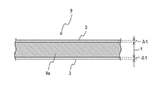
- solder 9 [Configuration example of solder 9] Next, a configuration example of the solder 9 applied with flux will be described with reference to FIGS. 5A and 5B.
- the solder 9 shown in FIG. 5B is obtained by controlling the film thickness of the flux 3 in the flux applying apparatus 100.
- the flux 3 is put into the flux tank 30 at a predetermined temperature (for example, 25 ° C.).
- the solder 9a is conveyed at a predetermined speed and immersed in the flux tank 30.
- the solder 9a immersed in the flux tank 30 is pulled up from the flux tank 30 perpendicularly to the liquid surface of the flux 3 indicated by a two-dot chain line in the figure (in the direction of the black arrow in the figure) at a conveyance speed v.
- an interfacial tension acts between the solder 9a and the flux 3, so that the flux 3 having a uniform film thickness corresponding to the conveyance speed v remains on the front and back of the solder 9a.
- the solder 9 pulled up vertically is subjected to a heat drying process and a cooling process. Further, the temperature of the solder 9 and the film thickness of the flux 3 are measured, conveyed, and wound to complete.
- the transfer speed v of the solders 9 and 9a can be controlled, so that the solder 9 covered with the flux 3 having a uniform film thickness can be manufactured.
- the flux 3 is applied to the surface of the solder 9a pulled up from the flux tank 30 with a uniform film thickness.
- the solder 9, 9a can be transported at a uniform transport speed v, so that the film thickness of the flux 3 covering the solder 9a can be controlled uniformly and 10 ⁇ m or less.
- the film thickness of the flux 3 covering the solder 9a can be controlled uniformly and 10 ⁇ m or less.
- solder 9 as an embodiment is pulled up vertically from the flux tank 30 containing the flux 3 and is transported at a uniform transport speed v.
- the film thickness of the flux 3 covering the solder 9 is made constant. Compared with the conventional method, a thin flux 3 having a superior coating surface stability and flatness can be applied to the solder 9.
- the flux coating apparatus 100 of this example has been described with respect to the case where a single piece of solder 9 is manufactured, it may be configured to simultaneously manufacture two or more pieces of solder 9. In that case, since many solders 9 can be manufactured at once, an operating cost can be reduced.
- the lifting roller 37, the transport rollers 31, 36, and 41 to 44 are driven rollers.
- it may be a constant speed conveying means that is provided with a motor (not shown) connected to the control unit 5 and whose rotation is controlled at a constant speed according to a desired conveying speed v.
- the flux tank 30 may be connected to a flux controller that controls the amount of the flux 3 to be stored or a sub-tank that stores the flux 3, and even if the components and amounts of the flux 3 stored in the flux tank 30 are constant. Good.
- the present invention is extremely suitable when applied to a flux coating apparatus that applies a flux to solder with a uniform film thickness and a solder formed by the flux coating apparatus.
Landscapes
- Engineering & Computer Science (AREA)
- Mechanical Engineering (AREA)
- Electric Connection Of Electric Components To Printed Circuits (AREA)
- Coating Apparatus (AREA)
Abstract
Description
1.フラックス塗布装置を長期間使用すると、フラックス塗布量を調整する部材(ダイス)にフラックスが付着して固形化し、均一な厚さにフラックスを塗布できなくなる。
2.はんだに塗布するフラックスの膜厚を変更したい場合、フラックス塗布量を調整する部材(ダイス)自体を交換する必要がある。
(1)はんだの表面にフラックスを塗布するフラックス塗布装置であって、はんだをフラックスに浸漬してはんだ表面にフラックスを塗布する浸漬塗布手段と、はんだを投入する側を上流側、はんだを排出する側を下流側としたとき、浸漬塗布手段より上流側に設けられ、はんだに所定の負荷を与える負荷手段と、浸漬塗布手段によりフラックスを塗布されてフラックスの液面に対して垂直に引き上げられるはんだを、負荷手段により負荷が加えられた状態で、所定の速度で搬送する定速搬送手段と、フラックスを塗布されたはんだを乾燥させる乾燥手段と、乾燥されたはんだを冷却する冷却手段と、はんだの搬送速度を計測する搬送速度計測手段と、はんだの搬送速度を制御する制御手段とを備えるフラックス塗布装置。
図1に示すフラックス塗布装置100は、一例として所定の幅を有する長尺の帯状に成形されたはんだの表面に均一膜厚のフラックス3を塗布する装置である。はんだの搬送方向に対して、長尺の帯状に成形されたはんだを繰り出し(供給)、フラックス槽30に投入する側、すなわち、図中左側が上流である。一方、フラックス槽30から排出し、はんだを巻き取る側、すなわち、右側が下流である。はんだは、上流から下流に搬送される。本例では、フラックス3塗布前のはんだをはんだ9a及びフラックス3塗布後のはんだをはんだ9として以下説明する。
続いて、図4を参照して、フラックス塗布装置100の制御手段の構成について説明する。制御部5は、はんだ9の搬送速度を制御するために、操作部14、表示装置15、繰り出しリール11、繰り出しバッファ・センサ13、巻取り器66、レーザ・センサ63、速度検知ローラー64等に接続する。
続いて、図5A及び図5Bを参照して、フラックス塗布されたはんだ9の構成例について説明する。図5Aに示すはんだ9は、所定の幅t(t=約15mm~40mm)、図示しない所定の厚み(約0.25mm)のフラックス塗布前のはんだ9aと、そのはんだ9aの表裏を被覆する膜厚Δtのフラックス3とを備えている。
2 フラックス塗布室
4 搬送部
5 制御部
6 巻取り部
11 繰り出しリール
13 繰り出しバッファ・センサ
14 操作部
15 表示装置
16 ブレーキローラー
20 加熱乾燥炉
21 ヒーター
24 遮熱エアカーテン
25 排気口
26 クーラー
27 はんだ用温度センサ
28 室内温度センサ
30 フラックス槽
63 レーザ・センサ
64 速度検知ローラー
66 巻取り器
100 フラックス塗布装置
Claims (5)
- はんだの表面にフラックスを塗布するフラックス塗布装置であって、
はんだをフラックスに浸漬してはんだ表面にフラックスを塗布する浸漬塗布手段と、
はんだを投入する側を上流側、はんだを排出する側を下流側としたとき、前記浸漬塗布手段より上流側に設けられ、はんだに所定の負荷を与える負荷手段と、
前記浸漬塗布手段によりフラックスを塗布されてフラックスの液面に対して垂直に引き上げられるはんだを、前記負荷手段により負荷が加えられた状態で、所定の速度で搬送する定速搬送手段と、
前記フラックスを塗布された前記はんだを乾燥させる乾燥手段と、
乾燥された前記はんだを冷却する冷却手段と、
前記はんだの搬送速度を計測する搬送速度計測手段と、
前記はんだの搬送速度を制御する制御手段と
を備えるフラックス塗布装置。 - 前記定速搬送手段は、搬送手段を備え、
この搬送手段は、
1以上の搬送ローラーを有し、
前記搬送ローラーは、前記はんだを挟む2つのローラー部材を有し、
前記ローラー部材が、前記はんだの両幅端を挟持する請求項1に記載のフラックス塗布装置。 - 少なくとも前記浸漬塗布手段、前記乾燥手段、前記冷却手段は、
フラックス塗布室内に収納されて、
前記フラックス塗布室は、
前記乾燥手段の外かつ前記フラックス塗布室内の熱気を排出する排気手段を更に備える請求項1または2に記載のフラックス塗布装置。 - 前記定速搬送手段は、巻き取り手段を備え、この巻き取り手段により前記はんだを巻き取る際に、層間紙を供給する層間紙供給手段を更に備える請求項1から3のいずれか1項に記載のフラックス塗布装置。
- 請求項1から4のいずれか1項に記載のフラックス塗布装置によって形成されるはんだ。
Priority Applications (9)
| Application Number | Priority Date | Filing Date | Title |
|---|---|---|---|
| KR1020177030619A KR101882156B1 (ko) | 2015-03-30 | 2015-03-30 | 플럭스 도포 장치 |
| US15/563,017 US10391589B2 (en) | 2015-03-30 | 2015-03-30 | Flux applying device |
| CN201580078611.0A CN109121402B (zh) | 2015-03-30 | 2015-03-30 | 焊剂涂敷装置 |
| EP15887510.4A EP3281739B1 (en) | 2015-03-30 | 2015-03-30 | Flux coating device and solder |
| PCT/JP2015/059899 WO2016157357A1 (ja) | 2015-03-30 | 2015-03-30 | フラックス塗布装置及びはんだ |
| ES15887510T ES2930723T3 (es) | 2015-03-30 | 2015-03-30 | Dispositivo de recubrimiento de fundente y soldadura |
| PT158875104T PT3281739T (pt) | 2015-03-30 | 2015-03-30 | Dispositivo de revestimento de fluxo e solda |
| JP2015531772A JP5825458B1 (ja) | 2015-03-30 | 2015-03-30 | フラックス塗布装置 |
| TW105109807A TWI572417B (zh) | 2015-03-30 | 2016-03-29 | 助焊劑塗布裝置 |
Applications Claiming Priority (1)
| Application Number | Priority Date | Filing Date | Title |
|---|---|---|---|
| PCT/JP2015/059899 WO2016157357A1 (ja) | 2015-03-30 | 2015-03-30 | フラックス塗布装置及びはんだ |
Publications (1)
| Publication Number | Publication Date |
|---|---|
| WO2016157357A1 true WO2016157357A1 (ja) | 2016-10-06 |
Family
ID=54776722
Family Applications (1)
| Application Number | Title | Priority Date | Filing Date |
|---|---|---|---|
| PCT/JP2015/059899 WO2016157357A1 (ja) | 2015-03-30 | 2015-03-30 | フラックス塗布装置及びはんだ |
Country Status (9)
| Country | Link |
|---|---|
| US (1) | US10391589B2 (ja) |
| EP (1) | EP3281739B1 (ja) |
| JP (1) | JP5825458B1 (ja) |
| KR (1) | KR101882156B1 (ja) |
| CN (1) | CN109121402B (ja) |
| ES (1) | ES2930723T3 (ja) |
| PT (1) | PT3281739T (ja) |
| TW (1) | TWI572417B (ja) |
| WO (1) | WO2016157357A1 (ja) |
Cited By (1)
| Publication number | Priority date | Publication date | Assignee | Title |
|---|---|---|---|---|
| EP3511108A1 (de) * | 2018-01-12 | 2019-07-17 | EMIL OTTO Flux- und Oberflächentechnik GmbH | Verfahren zur herstellung eines lotmittels |
Families Citing this family (5)
| Publication number | Priority date | Publication date | Assignee | Title |
|---|---|---|---|---|
| US10734349B2 (en) * | 2016-01-22 | 2020-08-04 | Capcon Limited | Apparatus and method for packaging components |
| KR101891594B1 (ko) * | 2016-11-11 | 2018-08-29 | 한국생산기술연구원 | 솔더일체형금속레이어, 이를 포함하는 솔더일체형pcb 및 솔더접합방법 |
| US10939600B2 (en) * | 2018-11-28 | 2021-03-02 | International Business Machines Corporation | Flux residue detection |
| CN113385364B (zh) * | 2021-06-10 | 2023-12-29 | 卢军飞 | 一种预张紧的土工布原材浸胶装置 |
| CN114473345A (zh) * | 2022-03-15 | 2022-05-13 | 中国电子科技集团公司第三十八研究所 | 一种高刚度可视化弹性焊接工装 |
Citations (2)
| Publication number | Priority date | Publication date | Assignee | Title |
|---|---|---|---|---|
| JPH03254392A (ja) * | 1990-02-28 | 1991-11-13 | Taiyo Yuden Co Ltd | シート状はんだおよびその製造方法 |
| JPH04111994A (ja) * | 1990-08-31 | 1992-04-13 | Showa Alum Corp | フラックス被覆された線状または板状ろう材及びその製造方法及び該ろう材を用いたろう付方法 |
Family Cites Families (35)
| Publication number | Priority date | Publication date | Assignee | Title |
|---|---|---|---|---|
| US2055393A (en) * | 1932-05-21 | 1936-09-22 | Standard Cap & Seal Corp | Wire with soldering flux coating and method of making the same |
| US3724418A (en) * | 1971-08-20 | 1973-04-03 | Lain J Mc | Solder coating apparatus |
| SE368348B (ja) * | 1973-01-29 | 1974-07-01 | Graenges Essem Ab | |
| JPS5475452A (en) | 1977-11-29 | 1979-06-16 | Senju Metal Industry Co | Flux coated solder wire and apparatus for coating flux on wire |
| US4619841A (en) * | 1982-09-13 | 1986-10-28 | Schwerin Thomas E | Solder leveler |
| US4499120A (en) * | 1982-09-29 | 1985-02-12 | General Dynamics, Pomona Division | Method for solder tinning of component leads |
| DE3420514C2 (de) * | 1984-06-01 | 1986-04-17 | Feindrahtwerk Adolf Edelhoff GmbH & Co, 5860 Iserlohn | Verfahren zur Herstellung verzinnter Drähte |
| US4790686A (en) * | 1986-04-10 | 1988-12-13 | Armco Inc. | Protected metal article |
| US4762808A (en) | 1987-06-22 | 1988-08-09 | Dow Corning Corporation | Method of forming semiconducting amorphous silicon films from the thermal decomposition of fluorohydridodisilanes |
| DE4105298C2 (de) | 1990-02-21 | 1996-04-11 | Bando Chemical Ind | Tauchanlage zur Anbringung von Klebe- oder Haftmitteln an Seilen |
| US5139822A (en) * | 1990-08-20 | 1992-08-18 | Amp Incorporated | Method for coating solder on selective areas of a metal strip |
| US5184767A (en) * | 1991-12-31 | 1993-02-09 | Compaq Computer Corporation | Non-wicking solder preform |
| JPH0649614A (ja) * | 1992-08-03 | 1994-02-22 | Kobe Steel Ltd | 耐食性及びはんだ付け性が優れた溶融錫めっき銅合金材の製造方法 |
| JPH07270436A (ja) * | 1994-03-31 | 1995-10-20 | Nkk Corp | 移動物体の測長装置 |
| JP3578291B2 (ja) * | 1995-09-08 | 2004-10-20 | 日本軽金属株式会社 | ろう付用組成物の塗布方法及びその装置 |
| JP3254392B2 (ja) | 1996-06-12 | 2002-02-04 | 株式会社リコー | 評価チャート及び画像記録装置 |
| JPH111994A (ja) | 1997-06-10 | 1999-01-06 | Shinbashikiichirou Shoten:Kk | 隙間付撚り線補強材 |
| TW415867B (en) * | 1998-07-29 | 2000-12-21 | Calsonic Corp | Method for applying flux for use in brazing aluminum material, flux coating apparatus, and method for manufacturing a heat exchanger |
| JP2001001136A (ja) | 1999-06-17 | 2001-01-09 | Furukawa Electric Co Ltd:The | フラックスが塗布されたアルミニウム合金製ろう付け用部材およびその製造方法 |
| CZ20021797A3 (cs) * | 1999-11-23 | 2002-11-13 | Norsk Hydro Asa | Hliníkový produkt s vynikajícími pájecími vlastnostmi a způsob jeho výroby |
| US6428851B1 (en) * | 2000-03-01 | 2002-08-06 | Bethlehem Steel Corporation | Method for continuous thermal deposition of a coating on a substrate |
| JP4112330B2 (ja) | 2002-10-02 | 2008-07-02 | 富士通株式会社 | 半導体装置の製造方法 |
| KR100465613B1 (ko) * | 2002-11-01 | 2005-01-13 | 태창엔지니어링 주식회사 | 전착 레지스트 코팅장치 |
| ES2751135T3 (es) * | 2006-05-25 | 2020-03-30 | Bellman Melcor Dev Llc | Alambre con fundente para soldadura fuerte y soldadura blanda y método de fabricación del mismo |
| US8291895B2 (en) * | 2007-09-05 | 2012-10-23 | University Of South Carolina | Methods, wires, and apparatus for slicing hard materials |
| JP5409059B2 (ja) * | 2009-03-16 | 2014-02-05 | Juki株式会社 | フラックス供給装置 |
| TWI446974B (zh) | 2009-06-30 | 2014-08-01 | Toray Eng Co Ltd | And a conveyor device for coating the substrate on both sides |
| CN101869885B (zh) * | 2010-02-04 | 2013-10-23 | 深圳市堃琦鑫华科技有限公司 | 超声波助焊剂涂覆方法及装置 |
| JP5367753B2 (ja) * | 2010-06-11 | 2013-12-11 | 古河電気工業株式会社 | 半田メッキ線の製造方法及び製造装置 |
| JP5703901B2 (ja) | 2011-03-31 | 2015-04-22 | 株式会社Ihi | ロールプレス装置及び膜厚計測方法 |
| JP5692170B2 (ja) * | 2012-06-11 | 2015-04-01 | 千住金属工業株式会社 | 溶融はんだ薄膜被覆装置、薄膜はんだ被覆部材及びその製造方法 |
| CN103056479B (zh) * | 2013-01-16 | 2014-12-31 | 中电电气(南京)光伏有限公司 | 一种用于太阳能光伏组件的助焊剂的喷涂方法及装置 |
| JP2015013248A (ja) | 2013-07-04 | 2015-01-22 | 株式会社豊田自動織機 | 塗工装置及び電極の製造方法 |
| EP3038790B1 (en) * | 2013-08-29 | 2018-02-21 | Alpha Assembly Solutions Inc. | Joining to aluminium |
| JP5884932B1 (ja) * | 2015-05-27 | 2016-03-15 | 千住金属工業株式会社 | 液体塗布装置 |
-
2015
- 2015-03-30 KR KR1020177030619A patent/KR101882156B1/ko active IP Right Grant
- 2015-03-30 JP JP2015531772A patent/JP5825458B1/ja active Active
- 2015-03-30 PT PT158875104T patent/PT3281739T/pt unknown
- 2015-03-30 EP EP15887510.4A patent/EP3281739B1/en active Active
- 2015-03-30 ES ES15887510T patent/ES2930723T3/es active Active
- 2015-03-30 US US15/563,017 patent/US10391589B2/en active Active
- 2015-03-30 CN CN201580078611.0A patent/CN109121402B/zh active Active
- 2015-03-30 WO PCT/JP2015/059899 patent/WO2016157357A1/ja active Application Filing
-
2016
- 2016-03-29 TW TW105109807A patent/TWI572417B/zh active
Patent Citations (2)
| Publication number | Priority date | Publication date | Assignee | Title |
|---|---|---|---|---|
| JPH03254392A (ja) * | 1990-02-28 | 1991-11-13 | Taiyo Yuden Co Ltd | シート状はんだおよびその製造方法 |
| JPH04111994A (ja) * | 1990-08-31 | 1992-04-13 | Showa Alum Corp | フラックス被覆された線状または板状ろう材及びその製造方法及び該ろう材を用いたろう付方法 |
Non-Patent Citations (1)
| Title |
|---|
| See also references of EP3281739A4 * |
Cited By (1)
| Publication number | Priority date | Publication date | Assignee | Title |
|---|---|---|---|---|
| EP3511108A1 (de) * | 2018-01-12 | 2019-07-17 | EMIL OTTO Flux- und Oberflächentechnik GmbH | Verfahren zur herstellung eines lotmittels |
Also Published As
| Publication number | Publication date |
|---|---|
| EP3281739A1 (en) | 2018-02-14 |
| CN109121402A (zh) | 2019-01-01 |
| TWI572417B (zh) | 2017-03-01 |
| KR101882156B1 (ko) | 2018-07-25 |
| PT3281739T (pt) | 2022-11-28 |
| ES2930723T3 (es) | 2022-12-21 |
| EP3281739A4 (en) | 2019-01-23 |
| KR20170125997A (ko) | 2017-11-15 |
| JP5825458B1 (ja) | 2015-12-02 |
| TW201637722A (zh) | 2016-11-01 |
| CN109121402B (zh) | 2019-12-03 |
| US20180185967A1 (en) | 2018-07-05 |
| EP3281739B1 (en) | 2022-09-14 |
| US10391589B2 (en) | 2019-08-27 |
| JPWO2016157357A1 (ja) | 2017-04-27 |
Similar Documents
| Publication | Publication Date | Title |
|---|---|---|
| JP5884932B1 (ja) | 液体塗布装置 | |
| JP5825458B1 (ja) | フラックス塗布装置 | |
| KR101958992B1 (ko) | 코팅 및 건조 시스템 | |
| JP5335319B2 (ja) | 塗布装置及び塗布方法 | |
| US5619807A (en) | Method and apparatus for processing a web of material | |
| EP3951299A1 (en) | Drying system and method for manufacturing coated metal plate | |
| JP2006297321A (ja) | 塗膜乾燥方法 | |
| JP2009030927A (ja) | ウェブの加熱冷却装置及びウェブの加熱冷却方法 | |
| JP2021084064A (ja) | 基板処理方法及び基板処理装置 | |
| JP7468205B2 (ja) | 光ファイバの製造装置 | |
| JP7453842B2 (ja) | 塗布膜の乾燥装置及び乾燥方法 | |
| US5342446A (en) | Apparatus for coating a continuous web | |
| JP2012178480A (ja) | 基板処理装置および基板処理方法 | |
| JP2023044788A (ja) | フィルムの製造方法 | |
| KR20010090316A (ko) | 마이카 테이프를 제조하기 위한 장치 및 방법 | |
| CN118043618A (zh) | 避免用于制造特别是罐的容器的烘炉发生故障的装置和方法 | |
| JP2000204477A (ja) | 絶縁皮膜塗布設備を有する高珪素鋼帯の連続製造設備 | |
| JP2004356653A (ja) | 樹脂封止方法および半導体チップ | |
| JP2013068404A (ja) | 塗布物の製造装置および製造方法 | |
| JP2004356652A (ja) | 樹脂封止方法および半導体チップ | |
| JP2004196471A (ja) | テープ状材料の搬送装置 | |
| JP2002273301A (ja) | 塗布装置及び塗布方法 | |
| JP2004336088A (ja) | 樹脂封止装置および半導体チップ | |
| JPH1057861A (ja) | 硬基板塗布方法および装置 | |
| JPH0785784A (ja) | 感光液塗布装置 |
Legal Events
| Date | Code | Title | Description |
|---|---|---|---|
| ENP | Entry into the national phase |
Ref document number: 2015531772 Country of ref document: JP Kind code of ref document: A |
|
| 121 | Ep: the epo has been informed by wipo that ep was designated in this application |
Ref document number: 15887510 Country of ref document: EP Kind code of ref document: A1 |
|
| NENP | Non-entry into the national phase |
Ref country code: DE |
|
| REEP | Request for entry into the european phase |
Ref document number: 2015887510 Country of ref document: EP |
|
| ENP | Entry into the national phase |
Ref document number: 20177030619 Country of ref document: KR Kind code of ref document: A |