WO2016152408A1 - 表示入力装置、表示入力装置の制御方法、表示入力装置の制御プログラム - Google Patents
表示入力装置、表示入力装置の制御方法、表示入力装置の制御プログラム Download PDFInfo
- Publication number
- WO2016152408A1 WO2016152408A1 PCT/JP2016/056263 JP2016056263W WO2016152408A1 WO 2016152408 A1 WO2016152408 A1 WO 2016152408A1 JP 2016056263 W JP2016056263 W JP 2016056263W WO 2016152408 A1 WO2016152408 A1 WO 2016152408A1
- Authority
- WO
- WIPO (PCT)
- Prior art keywords
- symbol
- display
- key
- input
- warning
- Prior art date
- Legal status (The legal status is an assumption and is not a legal conclusion. Google has not performed a legal analysis and makes no representation as to the accuracy of the status listed.)
- Ceased
Links
Images







Classifications
-
- G—PHYSICS
- G06—COMPUTING OR CALCULATING; COUNTING
- G06F—ELECTRIC DIGITAL DATA PROCESSING
- G06F3/00—Input arrangements for transferring data to be processed into a form capable of being handled by the computer; Output arrangements for transferring data from processing unit to output unit, e.g. interface arrangements
- G06F3/01—Input arrangements or combined input and output arrangements for interaction between user and computer
- G06F3/048—Interaction techniques based on graphical user interfaces [GUI]
- G06F3/0487—Interaction techniques based on graphical user interfaces [GUI] using specific features provided by the input device, e.g. functions controlled by the rotation of a mouse with dual sensing arrangements, or of the nature of the input device, e.g. tap gestures based on pressure sensed by a digitiser
- G06F3/0488—Interaction techniques based on graphical user interfaces [GUI] using specific features provided by the input device, e.g. functions controlled by the rotation of a mouse with dual sensing arrangements, or of the nature of the input device, e.g. tap gestures based on pressure sensed by a digitiser using a touch-screen or digitiser, e.g. input of commands through traced gestures
- G06F3/04886—Interaction techniques based on graphical user interfaces [GUI] using specific features provided by the input device, e.g. functions controlled by the rotation of a mouse with dual sensing arrangements, or of the nature of the input device, e.g. tap gestures based on pressure sensed by a digitiser using a touch-screen or digitiser, e.g. input of commands through traced gestures by partitioning the display area of the touch-screen or the surface of the digitising tablet into independently controllable areas, e.g. virtual keyboards or menus
-
- G—PHYSICS
- G06—COMPUTING OR CALCULATING; COUNTING
- G06F—ELECTRIC DIGITAL DATA PROCESSING
- G06F3/00—Input arrangements for transferring data to be processed into a form capable of being handled by the computer; Output arrangements for transferring data from processing unit to output unit, e.g. interface arrangements
- G06F3/01—Input arrangements or combined input and output arrangements for interaction between user and computer
- G06F3/048—Interaction techniques based on graphical user interfaces [GUI]
- G06F3/0484—Interaction techniques based on graphical user interfaces [GUI] for the control of specific functions or operations, e.g. selecting or manipulating an object, an image or a displayed text element, setting a parameter value or selecting a range
-
- H—ELECTRICITY
- H04—ELECTRIC COMMUNICATION TECHNIQUE
- H04N—PICTORIAL COMMUNICATION, e.g. TELEVISION
- H04N1/00—Scanning, transmission or reproduction of documents or the like, e.g. facsimile transmission; Details thereof
- H04N1/0035—User-machine interface; Control console
- H04N1/00352—Input means
- H04N1/00395—Arrangements for reducing operator input
-
- H—ELECTRICITY
- H04—ELECTRIC COMMUNICATION TECHNIQUE
- H04N—PICTORIAL COMMUNICATION, e.g. TELEVISION
- H04N1/00—Scanning, transmission or reproduction of documents or the like, e.g. facsimile transmission; Details thereof
- H04N1/0035—User-machine interface; Control console
- H04N1/00405—Output means
- H04N1/00408—Display of information to the user, e.g. menus
- H04N1/00411—Display of information to the user, e.g. menus the display also being used for user input, e.g. touch screen
-
- H—ELECTRICITY
- H04—ELECTRIC COMMUNICATION TECHNIQUE
- H04N—PICTORIAL COMMUNICATION, e.g. TELEVISION
- H04N1/00—Scanning, transmission or reproduction of documents or the like, e.g. facsimile transmission; Details thereof
- H04N1/0035—User-machine interface; Control console
- H04N1/00405—Output means
- H04N1/00408—Display of information to the user, e.g. menus
- H04N1/00413—Display of information to the user, e.g. menus using menus, i.e. presenting the user with a plurality of selectable options
- H04N1/00416—Multi-level menus
- H04N1/00419—Arrangements for navigating between pages or parts of the menu
- H04N1/00424—Arrangements for navigating between pages or parts of the menu using a list of graphical elements, e.g. icons or icon bar
-
- H—ELECTRICITY
- H04—ELECTRIC COMMUNICATION TECHNIQUE
- H04N—PICTORIAL COMMUNICATION, e.g. TELEVISION
- H04N1/00—Scanning, transmission or reproduction of documents or the like, e.g. facsimile transmission; Details thereof
- H04N1/0035—User-machine interface; Control console
- H04N1/00405—Output means
- H04N1/0049—Output means providing a visual indication to the user, e.g. using a lamp
-
- H—ELECTRICITY
- H04—ELECTRIC COMMUNICATION TECHNIQUE
- H04N—PICTORIAL COMMUNICATION, e.g. TELEVISION
- H04N2201/00—Indexing scheme relating to scanning, transmission or reproduction of documents or the like, and to details thereof
- H04N2201/0077—Types of the still picture apparatus
- H04N2201/0094—Multifunctional device, i.e. a device capable of all of reading, reproducing, copying, facsimile transception, file transception
Definitions
- the present invention relates to a display input device that accepts input of symbols such as letters, numbers, and marks.
- the present invention also relates to a display input device control method and a control program.
- Patent Document 1 displays a plurality of operation items, detects a pressed position when the touch panel is pressed, determines that at least one operation item is an input item, and presses the touch panel. When a predetermined range including the operation item corresponding to the pressed position at the time of pressing is enlarged and the touch panel is pressed, the operation item at the position corresponding to the last pressed position is determined as the input item. An input device is described. With this configuration, it is intended to improve operability (see Patent Document 1: Claim 1, paragraphs [0005], [0006], etc.).
- An image forming apparatus such as a multifunction peripheral as an example of a display input apparatus is provided with an operation panel for setting operation.
- a software keyboard may be displayed on the display panel in the operation panel.
- the user operates the software keyboard to input symbols such as letters, numbers, and marks. Thereby, for example, information such as an address and a user name can be registered.
- a software keyboard may be displayed for symbol input.
- the user moves the cursor or returns to the erroneously entered symbol in the backspace, and then inputs an appropriate symbol or deletes the wrong symbol.
- the software keyboard has a problem that it takes time to correct the symbols.
- another correct symbol may be deleted during correction, and the user may feel annoying.
- the present invention automatically displays a warning when there is a possibility that an incorrect symbol key has been operated, so that the user can be aware of an input error immediately after operating the incorrect symbol key.
- the display input device includes a display panel, a touch panel unit, and a control unit.
- the display panel displays a software keyboard screen including a plurality of symbol keys arranged and an input display field for displaying symbols corresponding to the symbol keys whose display positions are touched.
- the touch panel unit is provided on the display panel and detects a touch position of a user.
- the control unit recognizes an operated key that is a symbol key displayed at a user's touch position based on the output of the touch panel unit, and the touch position is a predetermined internal region of the region of the operated key.
- a warning target symbol which is a symbol corresponding to the operated key on which the outer peripheral area has been operated is displayed on the display panel in a manner different from the normal display.
- a warning is automatically displayed.
- the warning target symbol is emphasized by the warning display, and the user can notice an input error immediately after operating the wrong symbol key.
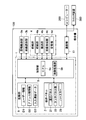
- 1 is a diagram illustrating an example of a multifunction machine according to an embodiment.
- 1 is a diagram illustrating an example of a multifunction machine according to an embodiment. It is a figure which shows an example of the software keyboard screen which concerns on embodiment. It is a figure which shows an example of the user registration screen which concerns on embodiment. It is a figure which shows an example of the address book registration screen which concerns on embodiment. It is a figure which shows an example of the warning display which concerns on embodiment. It is a figure which shows an example of the warning setting screen which concerns on embodiment. It is a figure which shows an example of the area
- Embodiments of the present invention will be described with reference to FIGS.
- the present invention can be applied to various types of apparatuses, but will be described by taking a multifunction peripheral 100 (corresponding to an image forming apparatus) as an example of the display input apparatus 1 as an example.
- a multifunction peripheral 100 corresponding to an image forming apparatus
- each element such as configuration and arrangement described in this embodiment does not limit the scope of the invention and is merely an illustrative example.
- the multifunction device 100 is provided with an operation panel 22 (shown by a broken line) on the front surface of the multifunction device 100.
- a document transport unit 3a and an image reading unit 3b are provided at the top.
- a printing unit 4 (a paper feeding unit 4a, a conveyance unit 4b, an image forming unit 4c, and a fixing unit 4d) that performs printing is provided inside the multifunction peripheral 100.
- the operation panel 2 includes a display panel 21 that displays the status of the multifunction peripheral 100, various messages, and various setting screens.
- a touch panel unit 22 is provided on the upper surface of the display panel 21.
- the touch panel unit 22 is for detecting the position and coordinates of the portion pressed on the display panel 21. Based on the output of the touch panel unit 22, the pressed operation image (image such as a soft key, a button, a tab, or a check box) is recognized.
- the operation panel 2 is also provided with a plurality of hard keys 23 such as a start key and a numeric keypad.
- the document transport unit 3a feeds the set documents one by one and continuously and automatically transports them toward the reading contact glass (reading position, not shown).
- the image reading unit 3b reads a document passing through the feed reading contact glass or a document set on a placement reading contact glass (not shown), and generates image data.
- the paper feed unit 4a accommodates a plurality of sheets, and feeds the sheets one by one to the transport unit 4b during a print job.
- the transport unit 4b transports the paper supplied from the paper feed unit 4a.
- the image forming unit 4c forms a toner image based on the image data, and transfers the toner image to the conveyed paper.
- the fixing unit 4d fixes the toner image transferred to the paper.
- the sheet after toner fixing is discharged to the discharge tray 4e.
- a control unit 5 is provided in the multifunction peripheral 100.
- the control unit 5 controls the operation of the multifunction device 100.
- the control unit 5 is connected to each unit such as the operation panel 2, the document conveyance unit 3 a, the image reading unit 3 b, the printing unit 4, and the communication unit 51 through a bus or a signal line.
- the control unit 5 controls operations of the multifunction peripheral 100 such as a scanning operation and a printing operation by controlling each unit.
- the control unit 5 includes circuits such as a CPU 5a and an image processing unit 5b.
- the CPU 5a performs control of each part of the multifunction peripheral 100 and various arithmetic processes based on the program and data stored in the storage unit 6.
- the image processing unit 5b performs image processing on the image data.
- the storage unit 6 is a combination of a nonvolatile storage device such as ROM and HDD and a volatile storage device such as RAM.
- the control unit 5 is connected to the communication unit 51.
- the communication unit 51 is communicably connected to the computer 200 and the facsimile apparatus 300 via a network, a public line, or a cable.
- the display input device 1 includes an operation panel 2 (a display panel 21 and a touch panel unit 22), a control unit 5, and a storage unit 6. It should be noted that a panel control unit that divides the functions of the control unit 5 and that is a board on which a memory is mounted and that recognizes a user's setting operation and switches the screen to the display panel 21 according to the operation may be provided. In this case, the operation panel 2 can be said to be the display input device 1.
- the display panel 21 displays operation images such as setting screens, keys, buttons, tabs, check boxes, and radio buttons.
- the control unit 5 controls display on the display panel 21.
- the touch panel unit 22 is provided above the display panel 21.
- the control unit 5 detects the touch position (coordinates) based on the output from the touch panel unit 22. Then, the control unit 5 recognizes that the operation image overlapping (displayed) with the touch position (coordinates) has been operated. Then, the control unit 5 causes the display panel 21 to display a screen corresponding to the operated operation image.
- the display input device 1 accepts input of symbol strings as user information and address information.
- Symbols are letters, numbers, marks, and the like. That is, alphabets and kanji characters can be input as symbols. Numbers and marks such as at, periods, and commas can be entered as symbols.
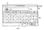
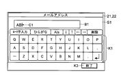
- the control unit 5 When inputting a symbol, the control unit 5 displays the software keyboard screen S1 on the display panel 21 (see FIG. 3).
- a plurality of symbol keys K1 are arranged in the software keyboard screen S1.
- FIG. 3 shows a state in which a plurality of symbol keys K1 are arranged.
- One symbol key K1 corresponds to one letter of the alphabet.
- Alphabet, kanji, and kana can be input by inputting alphabets or by converting kana by romaji input.
- the software keyboard screen S1 is also provided with an input display field B1 for displaying input results. By performing a predetermined operation, it is possible to input and display the symbol key K1 corresponding to various marks and symbols.
- the control unit 5 recognizes the operated symbol key K1 (operated key K1a) based on the output of the touch panel unit 22. And the control part 5 displays the result which the user input by operation in the input display column B1.
- FIG. 3 an example in which the user touches the symbol key K ⁇ b> 1 of “B” following “A” is illustrated.
- a position where a symbol is inserted when the symbol key K1 is touched is displayed, and a blinking vertical line (cursor C1) is displayed.
- the control unit 5 moves the position of the cursor C1 to the right side.
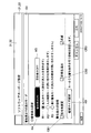
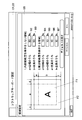
- FIG. 4 shows a user registration screen S2 for setting and registering user information.
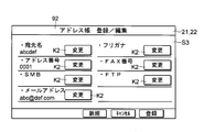
- FIG. 5 shows an address book registration screen S3 for registering item information related to the address book.
- An address such as an e-mail address, a network address, a FAX number, or the name of the other party is registered in the address book.
- the setting of the transmission destination can be completed only by selecting the address or the other party to be transmitted from the address book. You don't have to enter the address or name of the other party each time you send.
- the symbol input items are not limited to those related to user registration and address book, but are outside, but detailed description thereof is omitted.
- the user registration screen S2 and the address book registration screen S3 can be displayed on the display panel 21 by performing a predetermined operation.
- the names of symbol input items such as a user name, an address name, a password, an address, a pass, and a FAX number are displayed on each screen of user registration and address book registration. Then, the control unit 5 displays an already registered symbol string below the name of each symbol input item (see FIGS. 4 and 5).
- One change key K2 is attached to one symbol input item (see FIGS. 4 and 5).
- the user touches the display position of the change key K2 attached to the symbol input item to be newly registered or changed.
- the change key K2 corresponding to the e-mail address is operated.
- the control unit 5 causes the display panel 21 to display the software keyboard screen S1.
- the control unit 5 stores the contents of the input display field B1 when the end key K3 is operated on the software keyboard screen S1 in the storage unit 6 as data (user information D1, address book information D2) corresponding to the symbol input items.
- warning display in the display input device 1 according to the embodiment will be described with reference to FIGS.
- the user When inputting an address such as a pass, e-mail address or FAX number, the user touches and inputs any symbol key K1 a plurality of times. However, even if the person intends to touch the correct symbol key K1, the user may operate the wrong symbol key K1. Then, the user may continue to touch the symbol key K1 (operation on the symbol key K1) without noticing the mistake.
- an address such as a pass, e-mail address or FAX number
- control unit 5 determines whether there is a possibility that an input error has occurred. Then, when it is determined that there is a possibility of an input error, the control unit 5 displays a symbol (warning target symbol y1) corresponding to the operated key K1a that may cause an input error with a warning display different from the normal display. .
- the control unit 5 determines whether or not there is a possibility of an input error depending on the touch position on the symbol key K1. Specifically, the control unit 5 determines whether or not there is a possibility of an input error depending on whether the touch area belongs to the internal area F1 or the outer peripheral area F2 among the symbol keys K1.
- the internal area F1 is an area including the center of the display area of the display area of the symbol key K1 (operated key K1a) and having a predetermined size.
- the outer peripheral area F2 is an outer area (surrounding area) surrounding the inner area F1.
- the control unit 5 recognizes the operated symbol key K1 based on the output of the touch panel unit 22, and, based on the coordinates of the touch position, out of the region of the symbol key K1 where the touch position is operated, the inner region F1 and the outer periphery. It is determined which of the region F2 it belongs to.
- the control unit 5 When the internal area F1 is touched, the control unit 5 normally displays a symbol corresponding to the operated key K1a in the input display field B1.
- the control unit 5 displays a symbol corresponding to the operated key K1a in the input display field B1 in a color that is determined to be used for normal display such as black, without particularly emphasizing or modifying the display.
- FIG. 6 shows an example of a warning display.
- the background of the input display field B1 on the software keyboard screen S1 in FIG. 6 is white.
- the warning target symbol y ⁇ b> 1 is “B”.
- the symbol “B” in the input display field B1 is set to a predetermined emphasis character color such as red, highlighted (background color added), and normally displayed (black on a white background). Is displayed in a manner different from the symbol “A”. In this way, the control unit 5 displays a warning by changing and highlighting the display color of the symbol corresponding to the operated key K1a touched on the outer peripheral area F2.
- FIG. 7 is a diagram showing an example of the warning setting screen S4 as the setting screen.
- the control unit 5 displays a warning setting screen S ⁇ b> 4 on the display panel 21.
- the warning setting screen S4 is provided with an ON key K4 and an OFF key K5 for setting whether or not to display a warning. That is, the display panel 21 displays an ON key for performing a setting for displaying a warning and an OFF key for performing a setting for not performing a warning display. The user operates the ON key K4 when performing the warning display, and operates the OFF key K5 when setting the warning display not to be performed.
- the control unit 5 recognizes an operation on the ON key K4 and the OFF key K5 based on the output of the touch panel unit 22, and recognizes whether or not to perform a warning display. In the example shown in FIG. 7, the ON key K4 is operated and a setting for displaying a warning is made.
- the control unit 5 causes the display panel 21 to display the warning target symbol y1 only when the warning display is set by operating the ON key K4.
- the control unit 5 does not cause the display panel 21 to display the warning for the warning target symbol y1.
- the display input device 1 has a plurality of display modes as modes for displaying the warning target symbol y1 as a warning.
- Three radio buttons R1, R2, and R3 are provided on the warning setting screen S4 for selecting in which mode warning display is performed.
- the control unit 5 recognizes the position of the operated radio button and recognizes that the mode corresponding to the operated radio button has been selected. Details of each display mode will be described later.
- a check box CB1 for defining a warning display mode is provided. Changing the normal display and color (change from black to red), adding a color to the background of the warning target symbol y1 (highlighting), and selecting whether to flash the warning target symbol y1 it can. Note that at least one of the three check boxes CB1, CB2, and CB3 is checked.
- an area setting key K6 is provided (see FIG. 7).
- the control unit 5 displays an area setting screen S5 as shown in FIG.
- the region setting screen S5 is a screen for determining the sizes of the inner region F1 and the outer peripheral region F2 of the symbol key K1.
- the area setting screen S5 includes two numerical value input fields B2 and B3 for determining the size of the internal area F1, and four numerical value input fields B4, B5, B6, and B7 for determining the size of the outer peripheral area F2. Arranged.
- Each value of a to f can be determined by touching the display area of the number input field and operating the numeric keypad.
- a software keyboard screen S1 for inputting numbers is displayed, and the sizes of the internal area F1 and the outer peripheral area F2 are determined by input to this screen. Good.
- the ratio of the width of the inner region F1 to the width of the symbol key K1 (value of “a” in FIG. 8) and the ratio of the width of the left side of the outer peripheral region F2 to the width of the symbol key K1 ( The value of “c” in FIG. 8) and the ratio of the width on the right side of the outer peripheral area F2 to the horizontal width of the symbol key K1 (value of “d” in FIG. 8) can be determined. Note that the sum of the values of “a”, “c”, and “d” is 100%.
- the area of the symbol key K1 can be set to only the outer peripheral area F2, and the control unit 5 always displays a warning display when the symbol key K1 is operated when such setting is made. Let panel 21 do.
- control unit 5 causes the display panel 21 to display the area setting screen S5 for setting the sizes of the internal area F1 and the outer peripheral area F2. Then, the control unit 5 recognizes whether the touch position is the internal region F1 or the outer peripheral region F2 based on the size of each region set on the region setting screen S5.
- the re-input mode is a mode in which re-operation (retouch) of the same symbol key K1 is required to determine the warning target symbol y1. Preventing oversight of input mistakes by requiring re-input.
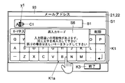
- the control unit 5 displays a message screen S6 on the display panel 21 (see FIG. 9).
- the message screen S6 includes a message for requesting an input error and re-input.
- the control unit 5 displays a message screen S6 on the display panel 21 so as to overlap the upper surface of the software keyboard screen S1.
- the control unit 5 displays a message screen S6 on the display panel 21 so as not to overlap the operated key K1a (symbol key K1 corresponding to the warning target symbol y1).
- the control unit 5 recognizes the retouching operation as an operation for determining that the warning target symbol y1 is an input symbol. Then, the control unit 5 causes the display panel 21 to cancel the warning display of the warning target symbol y1, and normally displays the warning target symbol y1. The user continues to input the next symbol.
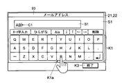
- FIG. 10 shows an example of the software keyboard screen S1 when the outer peripheral area F2 of “B” in FIG. 9 is touched and the message screen S6 is displayed and then the symbol key K1 of “B” is touched again.
- the control unit 5 recognizes that the input of the symbol “B” is correct.
- the control unit 5 recognizes an operation for another symbol key K1 as an instruction to correct the symbol corresponding to the key first touched after the message screen S6 is displayed. Then, the control unit 5 deletes the warning target symbol y1 (instead of the warning target symbol y1), and displays the corrected instruction symbol in the input display field B1 in the normal display.
- the control unit 5 recognizes the operation of continuing touching the symbol key K1 other than the symbol key K1 corresponding to the warning target symbol y1 a predetermined number of times as an operation for correcting the symbol. You may do it.
- the predetermined number of times can be determined as appropriate, and may be about 2 to 3 times.
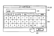
- FIG. 11 shows a case where the “N” symbol key K1 adjacent to the “B” symbol key K1 is operated after the message screen S6 is displayed by operating the “B” symbol key K1 in FIG.
- the control unit 5 recognizes that the symbol of “B” should be corrected to “N”. To do. Then, as shown in FIG. 11, the control unit 5 normally displays the symbol “N” instead of the warning target symbol y1 “B” displayed in the input display field B1.
- the input confirmation mode is a mode in which the input confirmation screen S7 including a plurality of keys for confirming whether or not the input is correct is displayed along with the display of the warning target symbol y1, and the user is surely confirmed whether or not there is an input mistake. It is. This prevents the symbol input from being continued in a state where there is a mistake.
- the control unit 5 displays the input confirmation screen S7 on the display panel 21 (see FIG. 12).
- the input confirmation screen S7 includes a message, a confirmation key K7, a deletion key K8, and a correction key K9.
- the control unit 5 displays an input confirmation screen S7 on the display panel 21 so as to overlap the upper surface of the software keyboard screen S1.
- the control unit 5 displays the input confirmation screen S7 on the display panel 21 so as not to overlap with the immediately preceding operated key K1a (the symbol key K1 corresponding to the warning target symbol y1).
- the control unit 5 determines the warning target symbol y1 as the input symbol. Then, the control unit 5 causes the display panel 21 to perform highlight addition, change the symbol color, or cancel the blinking display, and normally display the warning target symbol y1. The user can continue to input symbols.
- FIG. 13 shows an example of the software keyboard screen S1 when the confirmation key K7 is operated after the input confirmation screen S7 is displayed based on the operation of the symbol key K1 of “B”.
- the control unit 5 recognizes the operation of the confirmation key K7 as an operation of confirming the warning target symbol y1, and recognizes that the input of the symbol “B” (warning target symbol y1) is correct. And as shown in FIG. 13, the control part 5 cancels
- the user touches the delete key K8.
- the deletion key K8 is touched (operated)
- the control unit 5 recognizes that the warning target symbol y1 should be deleted. Then, the control unit 5 deletes the warning target symbol y1 from the input display field B1. The user can simply input the correct symbol.
- FIG. 14 shows an example of the software keyboard screen S1 when the delete key K8 is operated after the input confirmation screen S7 is displayed based on the operation of the symbol key K1 “B” in FIG.
- the control unit 5 puts the “B” symbol in the input display field B1 into a state of being erased.
- the control unit 5 recognizes the touch (operation) of the correction key K9 as an instruction to correct the warning target symbol y1 to the symbol corresponding to the symbol key K1 touched next to the touch of the correction key K9. Then, the control unit 5 deletes the warning target symbol y1 (instead of the warning target symbol y1), and normally displays the corrected symbol in the input display field B1.
- FIG. 15 shows an example in which the symbol key K1 “B” in FIG. 12 is corrected to the symbol “J” close to the symbol key K1 “B” after the input confirmation screen S7 is displayed by operation.
- the control unit 5 recognizes that the symbol “B” should be corrected to “J”. To do.
- the control unit 5 normally displays the symbol “J” on the display panel 21 instead of the warning target symbol y1 “B” displayed in the input display field B1.
- the warning symbol y1 is displayed.
- the minimum warning mode overlaps the screen such as the message screen S6 or the input confirmation screen S7 on the software keyboard screen S1 even if the outer peripheral area F2 of the operated key K1a is touched. The mode is not displayed.
- the warning display of the symbol corresponding to the symbol key K1 whose touch position belongs to the outer peripheral area F2 is made.
- the difference from normal symbol input is only that a warning is displayed for the warning target symbol y1, and the other points remain unchanged.
- Items related to address registration such as e-mail address, FAX number, and network address are also a kind of symbol input items. If the registered address contains an input error, a communication error may occur and data may not be transmitted correctly. In addition, the redial function may repeat meaningless retransmissions. Also, if the FAX number is incorrect, there is a possibility that data will be transmitted to a transmission destination that has nothing to do with it. As described above, it is not particularly preferable to overlook an address input mistake.
- the control unit 5 uses symbol keys rather than the software keyboard screen S1 for symbol input items other than addresses.
- the ratio of the outer peripheral area F2 of K1 is increased. Thereby, the warning display, the message screen S6, and the input confirmation screen S7 are easily displayed, and input errors are less likely to occur.
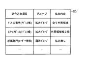
- each symbol input item is assigned to either an expanded group or a normal group.
- the normal group is a group that defines the inner region F1 and the outer peripheral region F2 based on the size of each region set on the region setting screen S5.
- the expansion group is a group in which the ratio of the outer peripheral region F2 is increased as compared with the case of inputting symbols for items of the normal group.
- Input item data D3 indicating which group each symbol input item belongs to is stored in the storage unit 6 (see FIG. 2).
- FIG. 16 shows an example of the input item data D3.
- a group to which each symbol input item belongs is determined.
- the increasing rate of the width of the outer peripheral region F2 in the symbol input items belonging to the expansion group may be constant.
- information that defines how much the outer peripheral area F2 is enlarged may be defined (see FIG. 16).
- the symbol input item of the FAX number in the address book is an expanded group and all the regions of the symbol key K1 are the outer peripheral region F2.
- a symbol key K1 that may cause an input error and a symbol key K1b adjacent to the symbol key K1 are temporarily stored.
- Zoom in on. 9 to 15 show a state that is not enlarged. Whether or not to enlarge the display can be set on the operation panel 2.
- the control unit 5 causes the display panel 21 to perform enlarging display.
- the control unit 5 causes the display panel 21 to display the symbol key K1 that is not enlarged.
- the control unit 5 When the position touched by the operated key K1a belongs to the outer peripheral area F2, the control unit 5 causes the display panel 21 to display a warning according to the display mode. When the display is enlarged, the control unit 5 displays the operated key K1a touched on the outer peripheral area F2 and the symbol key K1b adjacent to the operated key K1a on the display panel 21 while displaying the warning. Zoom in. As the warning target symbol y1 is confirmed, corrected, and deleted, the control unit 5 returns the size of the symbol key K1 to the normal size.
- FIG. 17 shows an example of expansion of the symbol key K1 during warning display.
- the warning target symbol y1 symbol in the warning display state
- the control unit 5 expands the symbol key K1 of “B” and the symbol keys K1 of “H”, “V”, and “N” adjacent to the symbol key K1 of “B”.
- the display is performed on the display panel 21.
- the control unit 5 causes the display panel 21 to further display a message screen S6 in the re-input mode and further display an input confirmation screen S7 in the input confirmation mode.
- the display input device 1 includes the display panel 21, the touch panel unit 22, and the control unit 5.
- the display panel 21 displays a plurality of symbol keys K1 arranged in the software keyboard screen S1 for inputting symbols and a symbol corresponding to the symbol key K1 whose display position is touched in the input display field B1.
- the touch panel unit 22 is provided on the display panel 21 and the display panel 21 and detects the touch position of the user.
- the control unit 5 recognizes the operated key K1a that is the symbol key K1 displayed at the touch position of the user based on the output of the touch panel unit 22, and the touch position is predetermined in the region of the operated key K1a.
- a symbol corresponding to the operated key K1a is normally displayed in the input display field B1, and the outer peripheral area F2 that is an area outside the internal area F1 in the area of the operated key K1a.
- a warning target symbol y1 that is a symbol corresponding to the operated key K1a in which the outer peripheral area F2 is operated is displayed on the display panel 21 in a manner different from the normal display.
- the user When the position off the center of the symbol key K1 is touched, the user may have operated the wrong symbol key K1.
- the display input device 1 of the present embodiment when there is a possibility that the symbol key K1b adjacent to the symbol key K1 to be operated is touched by mistake, the symbol corresponding to the operated key K1a is displayed in a state different from the normal state. Can be made. Thereby, the user notices that there was an input error immediately after touching the symbol key K1. Since an erroneous symbol can be corrected immediately even if there is an input error, correction can be made more easily than when an input error is noticed after inputting a plurality of symbols.
- the display input device 1 has a plurality of display modes as modes for displaying the warning target symbol y1 in a warning display.
- the control unit 5 uses the same symbol key as the symbol key K1 corresponding to the warning target symbol y1 when the outer peripheral area F2 of the operated key K1a is operated.
- a message screen S6 for retouching K1 is displayed on the display panel 21, and the operation of retouching the same symbol key K1 after the message screen S6 is displayed is recognized as an operation for determining the warning target symbol y1, and the warning target symbol y1 Is switched to the display panel 21 from the warning display to the normal display.
- the control unit 5 does not retouch the same symbol key K1 after displaying the message screen S6, and does not perform any touch on the symbol key K1 other than the symbol key K1 corresponding to the warning target symbol y1.
- the warning target symbol y1 is recognized as an operation to correct the symbol corresponding to the touched symbol key K1, and is changed to the warning target symbol y1, and the corrected symbol is displayed in the normal display. 21 is displayed.
- the predetermined number of times can be determined as appropriate, for example, twice.
- the control unit 5 includes an input including the enter key K7, the delete key K8, and the correction key K9.
- the confirmation screen S7 is displayed on the display panel 21, and the touch on the confirmation key K7 is recognized as an operation for confirming the warning target symbol y1, and the display state of the warning target symbol y1 is switched from the warning display to the normal display.
- the touch on the delete key K8 is recognized as an operation for instructing the deletion of the warning target symbol y1
- the display of the warning target symbol y1 is turned off on the display panel 21, and the touch on the correction key K9 is changed to the touch of the correction key K9.
- the operation is recognized as an operation of correcting the warning target symbol y1 to the symbol corresponding to the touched symbol key K1, and the corrected symbol is changed to the warning target symbol y1 in the normal display. To be displayed on.
- the symbol key K1 is touched by mistake, it is possible to confirm whether or not the input symbol is correct by operating the key displayed on the input confirmation screen S7, or to check the warning target symbol y1. Can be deleted or corrected to the correct symbol.
- the control unit 5 displays the warning target symbol y1 in a warning display and adds it to the software keyboard screen S1. A separate screen from the message is not displayed on the display panel 21. Thus, only the warning display can be performed when there is a possibility that the symbol key K1 is touched by mistake according to the user's wish.
- the display panel 21 displays an area setting screen S5 for setting the sizes of the internal area F1 and the outer peripheral area F2.
- the control unit 5 recognizes whether the touch position is the internal region F1 or the outer peripheral region F2 based on the size of each region set on the region setting screen S5. Thereby, it becomes easy to display warning, re-input, and reconfirmation by enlarging the outer periphery area
- the display frequency of warning, re-input, and re-confirmation can be set according to the user's preference, and the strength of input error prevention can be adjusted.
- a plurality of symbol input items for inputting symbols are provided, and each symbol input item is assigned to either an expanded group or a normal group.
- the control unit 5 increases the ratio of the outer peripheral area F2 when inputting a symbol input item belonging to the expansion group, compared to when inputting a symbol of the normal group, and the expansion group includes a symbol input item that determines the address of the communication partner. . This makes it easier to display warnings for specific symbol input items such as addresses that should be prevented from being mistaken. And in the item which belongs to an expansion group, possibility that correct information will be input and set can be raised more.
- control unit 5 displays the warning target symbol y1 in a warning display by either changing the display color of the symbol in the normal display, changing the background color of the symbol in the normal display, or both. It is displayed on the display panel 21. Thereby, when there is a possibility that the symbol key K1 is touched by mistake, the warning target symbol y1 in the input display field B1 can be made conspicuous.
- the control unit 5 enlarges and displays the operated key K1a and the symbol key K1b adjacent to the operated key K1a on the display panel 21. As a result, the keys that may be operated for correction or re-input are enlarged and displayed so that no mistake occurs in the next input (touch of the symbol key K1).
- the image forming apparatus includes the display input device 1 described above.
- the user can immediately notice a symbol input error and provide an image forming apparatus (multifunction device 100) that can easily input the symbol. Can do.
- the present invention can also be regarded as a control method for the display input device 1.
- the present invention can also be understood as a control program for the display input device 1.
- the warning symbol y1 is displayed on the display / input device 1 as a warning so as to appeal to the user's eyes and immediately notice the input error of the symbol, thereby improving the ease of inputting the symbol on the display / input device 1. Can do.
- the present invention can be used for a display input device having a display panel and a touch panel unit, and an image forming apparatus.
Landscapes
- Engineering & Computer Science (AREA)
- Human Computer Interaction (AREA)
- General Engineering & Computer Science (AREA)
- Theoretical Computer Science (AREA)
- Multimedia (AREA)
- Signal Processing (AREA)
- Physics & Mathematics (AREA)
- General Physics & Mathematics (AREA)
- Input From Keyboards Or The Like (AREA)
- User Interface Of Digital Computer (AREA)
Abstract
Description
次に、図1、図2に基づき、実施形態に係る複合機100の概略を説明する。
次に、図2を用いて、実施形態に係る表示入力装置1を説明する。表示入力装置1は、操作パネル2(表示パネル21、タッチパネル部22)、制御部5、記憶部6を含む。なお、制御部5の機能を分割し、メモリーを搭載した基板であり使用者の設定操作を認識し操作に応じ画面を表示パネル21に切り替えさせるパネル制御部を設けてもよい。この場合、操作パネル2が表示入力装置1といえる。
次に、図3~図6に基づき、実施形態に係る表示入力装置1での記号入力の一例を説明する。
次に、図6~図8に基づき、実施形態に係る表示入力装置1での警告表示について説明する。
次に、図9~図11に基づき、実施形態に係る表示入力装置1での再入力モードでの警告表示を説明する。
次に、図12~図15に基づき、実施形態に係る表示入力装置1での入力確認モードでの警告表示を説明する。
次に、図7に基づき、実施形態に係る表示入力装置1での最小警告モードでの警告表示を説明する。
次に、図16を用いて、実施形態に係る自動的な外周領域F2の面積拡大を説明する。
次に、図17に基づき、実施形態に係る記号キーK1の拡大表示を説明する。
Claims (13)
- 複数並べられた記号キーと、表示位置がタッチされた記号キーに対応する記号を表示する入力表示欄を含むソフトウェアキーボード画面を表示する表示パネルと、
前記表示パネルに対して設けられ、使用者のタッチ位置を検知するためのタッチパネル部と、
前記タッチパネル部の出力に基づき使用者のタッチ位置に表示された記号キーである被操作キーを認識し、タッチ位置が前記被操作キーの領域のうちの予め定められた内部領域であるとき、前記被操作キーに対応する記号を前記入力表示欄に通常表示させ、タッチ位置が前記被操作キーの領域のうち、前記内部領域よりも外側の領域である外周領域であるとき、前記外周領域が操作された前記被操作キーに対応する記号である警告対象記号を前記通常表示と異なる態様で前記表示パネルに警告表示させる制御部と、を含むことを特徴とする表示入力装置。 - 前記警告対象記号を警告表示で表示するときのモードとして複数の表示モードを有し、
前記表示モードのうち再入力モードが予め選択されている場合、
前記制御部は、前記被操作キーの前記外周領域が操作されたとき、前記警告対象記号に対応する記号キーと同じ記号キーの再タッチを求めるメッセージ画面を前記表示パネルに表示させ、前記メッセージ画面の表示後に前記同じ記号キーを再タッチする操作を、前記警告対象記号を確定する操作と認識し、前記警告対象記号の表示状態を前記警告表示から前記通常表示へと前記表示パネルに切り替えさせることを特徴とする請求項1に記載の表示入力装置。 - 前記制御部は、前記メッセージ画面を表示した後に前記同じ記号キーの再タッチがなされず、前記警告対象記号に対応する記号キー以外の何れか1つの記号キーに対するタッチが所定回数なされたとき、前記警告対象記号をタッチがなされた記号キーに対応する記号に修正する操作と認識し、前記警告対象記号に変えて、修正された記号を通常表示で前記表示パネルに表示させることを特徴とする請求項2に記載の表示入力装置。
- 前記警告対象記号を警告表示で表示するときのモードとして複数の表示モードを有し、
前記表示モードのうち入力確認モードが予め選択されている場合、
前記被操作キーの前記外周領域が操作されたとき、前記制御部は、確定キーと削除キーと修正キーを含む入力確認画面を前記表示パネルに表示させ、前記確定キーへのタッチを、前記警告対象記号を確定する操作と認識し、前記警告対象記号の表示状態を前記警告表示から前記通常表示へと前記表示パネルに切り替えさせ、前記削除キーへのタッチを前記警告対象記号の削除を指示する操作と認識し、前記警告対象記号の表示を前記表示パネルに消させ、前記修正キーへのタッチを前記修正キーのタッチの次にタッチされた記号キーに対応する記号に前記警告対象記号を修正する操作と認識し、前記警告対象記号に変えて修正後の記号を通常表示で前記表示パネルに表示させることを特徴とする請求項1に記載の表示入力装置。 - 前記警告対象記号を警告表示で表示するときの表示モードとして複数のモードを有し、
複数の前記表示モードのうち最小警告モードが選択されている場合、
前記制御部は、前記被操作キーの前記外周領域が操作されたとき、前記警告対象記号を前記警告表示で表示させるとともに、前記ソフトウェアキーボード画面に追加のメッセージと画面を前記表示パネルに表示させないことを特徴とする請求項1に記載の表示入力装置。 - 前記表示パネルは、前記内部領域と前記外周領域の大きさを設定するための領域設定画面を表示し、
前記制御部は、前記領域設定画面で設定された各領域の大きさに基づき、タッチ位置が前記内部領域であるか前記外周領域であるかを認識することを特徴とする請求項1に記載の表示入力装置。 - 前記領域設定画面には、
記号キーの横方向に関し、記号キーの横幅に対する前記内部領域の横幅の割合と、記号キーの横幅に対する前記外周領域の左側の幅の割合と、記号キーの横幅に対する前記外周領域の右側の幅の割合を定めるための数値入力欄と、
記号キーK1の縦方向に関し、記号キーK1の縦幅に対する前記内部領域の縦幅の割合と、記号キーの縦幅に対する前記外周領域の上側の幅の割合と、記号キーの縦幅に対する前記外周領域の下側の幅の割合を定めるため数値入力欄が設けられることを特徴とする請求項6に記載の表示入力装置。 - 記号を入力する記号入力項目が複数設けられ、各前記記号入力項目は拡大グループと通常グループの何れかに振り分けられており、
前記制御部は、前記拡大グループに属する前記記号入力項目の記号入力のとき、前記通常グループの記号入力時よりも前記外周領域の割合を増加させ、
前記拡大グループは、通信相手のアドレスを定める前記記号入力項目を含むことを特徴とする請求項1に記載の表示入力装置。 - 前記制御部は、前記通常表示での記号の表示色を異ならせることと、前記通常表示での記号の背景色を異ならせることの何れか一方、又は、両方によって前記警告対象記号を前記警告表示で前記表示パネルに表示させることを特徴とする請求項1に記載の表示入力装置。
- 前記制御部は、前記被操作キーの前記外周領域が操作されたとき、前記被操作キーと、前記被操作キーに隣接する記号キーを前記表示パネルに拡大表示させることを特徴とする請求項1に記載の表示入力装置。
- 前記表示パネルは、警告表示を行う設定を行うためのONキーと警告表示を行わない設定を行うためOFFキーを表示し、
前記制御部は、前記タッチパネル部の出力に基づき警告表示を行うか否かを認識し、前記警告表示を行う設定がなされているときのみ前記警告対象記号の前記警告表示を前記表示パネルに行わせ、前記警告表示を行わない設定がなされているとき、前記警告対象記号の前記警告表示を前記表示パネルに行わせないことを特徴とする請求項1に記載の表示入力装置。 - 記号の入力を行うためのソフトウェアキーボード画面内に、複数並べられた記号キーと表示位置がタッチされた記号キーに対応する記号を入力表示欄内に表示し、
使用者のタッチ位置を検知し、
使用者のタッチ位置に表示された記号キーである被操作キーを認識し、
タッチ位置が前記被操作キーの領域のうちの予め定められた内部領域であるとき、前記被操作キーに対応する記号を前記入力表示欄に通常表示し、
タッチ位置が前記被操作キーの領域のうち、前記内部領域よりも外側の領域である外周領域であるとき、前記外周領域が操作された前記被操作キーに対応する記号である警告対象記号を前記通常表示と異なる態様で表示することを特徴とする表示入力装置の制御方法。 - 表示入力装置に、
記号の入力を行うためのソフトウェアキーボード画面内に、複数並べられた記号キーと表示位置がタッチされた記号キーに対応する記号を入力表示欄内に表示させ、
使用者のタッチ位置を検知させ、
使用者のタッチ位置に表示された記号キーである被操作キーを認識させ、
タッチ位置が前記被操作キーの領域のうちの予め定められた内部領域であるとき、前記被操作キーに対応する記号を前記入力表示欄に通常表示させ、
タッチ位置が前記被操作キーの領域のうち、前記内部領域よりも外側の領域である外周領域であるとき、前記外周領域が操作された前記被操作キーに対応する記号である警告対象記号を前記通常表示と異なる態様で表示させる表示入力装置の制御プログラム。
Priority Applications (3)
| Application Number | Priority Date | Filing Date | Title |
|---|---|---|---|
| US15/323,324 US9753641B2 (en) | 2015-03-26 | 2016-03-01 | Display input device, control method for display input device, and computer-readable storage medium for storing control program for display input device |
| CN201680002094.3A CN106537296B (zh) | 2015-03-26 | 2016-03-01 | 显示输入装置及其控制方法和存储介质 |
| JP2016574295A JP6101879B2 (ja) | 2015-03-26 | 2016-03-01 | 表示入力装置、表示入力装置の制御方法、表示入力装置の制御プログラム |
Applications Claiming Priority (2)
| Application Number | Priority Date | Filing Date | Title |
|---|---|---|---|
| JP2015-064880 | 2015-03-26 | ||
| JP2015064880 | 2015-03-26 |
Publications (1)
| Publication Number | Publication Date |
|---|---|
| WO2016152408A1 true WO2016152408A1 (ja) | 2016-09-29 |
Family
ID=56978105
Family Applications (1)
| Application Number | Title | Priority Date | Filing Date |
|---|---|---|---|
| PCT/JP2016/056263 Ceased WO2016152408A1 (ja) | 2015-03-26 | 2016-03-01 | 表示入力装置、表示入力装置の制御方法、表示入力装置の制御プログラム |
Country Status (4)
| Country | Link |
|---|---|
| US (1) | US9753641B2 (ja) |
| JP (1) | JP6101879B2 (ja) |
| CN (1) | CN106537296B (ja) |
| WO (1) | WO2016152408A1 (ja) |
Cited By (3)
| Publication number | Priority date | Publication date | Assignee | Title |
|---|---|---|---|---|
| CN106952655A (zh) * | 2017-02-23 | 2017-07-14 | 深圳市金立通信设备有限公司 | 一种输入方法和终端 |
| CN109491515A (zh) * | 2018-10-23 | 2019-03-19 | 维沃移动通信有限公司 | 一种输入方法、终端 |
| WO2019230181A1 (ja) * | 2018-05-29 | 2019-12-05 | 京セラドキュメントソリューションズ株式会社 | 入力制御装置、及び入力制御方法 |
Families Citing this family (3)
| Publication number | Priority date | Publication date | Assignee | Title |
|---|---|---|---|---|
| CN106537296B (zh) * | 2015-03-26 | 2020-03-20 | 京瓷办公信息系统株式会社 | 显示输入装置及其控制方法和存储介质 |
| US11347749B2 (en) * | 2018-05-24 | 2022-05-31 | Sap Se | Machine learning in digital paper-based interaction |
| KR102257719B1 (ko) * | 2018-11-21 | 2021-05-28 | 오세호 | 작성프로그램 및 이를 탑재한 문자 입력 장치 |
Citations (3)
| Publication number | Priority date | Publication date | Assignee | Title |
|---|---|---|---|---|
| JPH02287609A (ja) * | 1989-04-28 | 1990-11-27 | Toshiba Corp | タッチスクリーン入力装置 |
| JP2006285598A (ja) * | 2005-03-31 | 2006-10-19 | Fujitsu Ten Ltd | タッチパネル装置、タッチパネル装置の操作支援方法、及びタッチパネル装置の操作支援プログラム |
| JP2015032016A (ja) * | 2013-07-31 | 2015-02-16 | シャープ株式会社 | 情報処理装置、および情報処理プログラム |
Family Cites Families (17)
| Publication number | Priority date | Publication date | Assignee | Title |
|---|---|---|---|---|
| JP2002091677A (ja) | 2000-09-14 | 2002-03-29 | Sanyo Electric Co Ltd | 入力装置及び情報端末装置 |
| WO2010083821A1 (de) * | 2009-01-26 | 2010-07-29 | Alexander Gruber | Verfahren zur steuerung eines auf einem bildschirm dargestellten auswahlobjekts |
| US8498181B1 (en) * | 2009-03-20 | 2013-07-30 | Eugene R. Bath | Alarm clock touch screen application |
| CN101706689B (zh) * | 2009-11-25 | 2013-03-13 | 福州福昕软件开发有限公司 | 通过方向键进行字符输入的方法和装置 |
| CN101814002A (zh) * | 2010-03-24 | 2010-08-25 | 华为终端有限公司 | 虚拟键盘及应用该虚拟键盘的输入方法 |
| US20120206370A1 (en) * | 2011-02-10 | 2012-08-16 | Research In Motion Limited | Method and apparatus for displaying keys of a virtual keyboard |
| WO2012144984A1 (en) * | 2011-04-19 | 2012-10-26 | Hewlett-Packard Development Company, L.P. | Touch screen selection |
| TWI453628B (zh) * | 2012-01-12 | 2014-09-21 | Amtran Technology Co Ltd | 適應性調整虛擬按鍵尺寸的方法及其顯示裝置 |
| JP2013206003A (ja) * | 2012-03-27 | 2013-10-07 | Fujitsu Ltd | キー入力装置及びキー誤入力可能性判断プログラム |
| CN102968602B (zh) * | 2012-10-31 | 2016-04-20 | 北京奇虎科技有限公司 | 一种键盘的设置方法和装置 |
| JP2015535628A (ja) * | 2012-11-27 | 2015-12-14 | トムソン ライセンシングThomson Licensing | 適応的な仮想キーボード |
| US10048861B2 (en) * | 2012-11-27 | 2018-08-14 | Thomson Licensing | Adaptive virtual keyboard |
| JP6040034B2 (ja) * | 2013-01-17 | 2016-12-07 | 日立オムロンターミナルソリューションズ株式会社 | 取引処理装置及び取引処理方法 |
| WO2014139209A1 (en) * | 2013-03-11 | 2014-09-18 | City University Of Hong Kong | Regional zooming virtual keyboards for accurate typing on small displays |
| KR20140144432A (ko) * | 2013-06-11 | 2014-12-19 | 삼성전자주식회사 | 휴대 단말기에서 입력된 문자를 표시하는 방법 및 장치 |
| US9146623B1 (en) * | 2013-08-22 | 2015-09-29 | Google Inc. | Systems and methods for registering key inputs |
| CN106537296B (zh) * | 2015-03-26 | 2020-03-20 | 京瓷办公信息系统株式会社 | 显示输入装置及其控制方法和存储介质 |
-
2016
- 2016-03-01 CN CN201680002094.3A patent/CN106537296B/zh not_active Expired - Fee Related
- 2016-03-01 JP JP2016574295A patent/JP6101879B2/ja not_active Expired - Fee Related
- 2016-03-01 US US15/323,324 patent/US9753641B2/en not_active Expired - Fee Related
- 2016-03-01 WO PCT/JP2016/056263 patent/WO2016152408A1/ja not_active Ceased
Patent Citations (3)
| Publication number | Priority date | Publication date | Assignee | Title |
|---|---|---|---|---|
| JPH02287609A (ja) * | 1989-04-28 | 1990-11-27 | Toshiba Corp | タッチスクリーン入力装置 |
| JP2006285598A (ja) * | 2005-03-31 | 2006-10-19 | Fujitsu Ten Ltd | タッチパネル装置、タッチパネル装置の操作支援方法、及びタッチパネル装置の操作支援プログラム |
| JP2015032016A (ja) * | 2013-07-31 | 2015-02-16 | シャープ株式会社 | 情報処理装置、および情報処理プログラム |
Cited By (4)
| Publication number | Priority date | Publication date | Assignee | Title |
|---|---|---|---|---|
| CN106952655A (zh) * | 2017-02-23 | 2017-07-14 | 深圳市金立通信设备有限公司 | 一种输入方法和终端 |
| WO2019230181A1 (ja) * | 2018-05-29 | 2019-12-05 | 京セラドキュメントソリューションズ株式会社 | 入力制御装置、及び入力制御方法 |
| JPWO2019230181A1 (ja) * | 2018-05-29 | 2021-06-24 | 京セラドキュメントソリューションズ株式会社 | 入力制御装置、及び入力制御方法 |
| CN109491515A (zh) * | 2018-10-23 | 2019-03-19 | 维沃移动通信有限公司 | 一种输入方法、终端 |
Also Published As
| Publication number | Publication date |
|---|---|
| JP6101879B2 (ja) | 2017-03-22 |
| US9753641B2 (en) | 2017-09-05 |
| JPWO2016152408A1 (ja) | 2017-04-27 |
| CN106537296B (zh) | 2020-03-20 |
| US20170131897A1 (en) | 2017-05-11 |
| CN106537296A (zh) | 2017-03-22 |
Similar Documents
| Publication | Publication Date | Title |
|---|---|---|
| JP6101879B2 (ja) | 表示入力装置、表示入力装置の制御方法、表示入力装置の制御プログラム | |
| JP5923477B2 (ja) | 表示入力装置、画像形成装置 | |
| JP5938389B2 (ja) | 表示入力装置及びこれを備えた画像形成装置 | |
| US8988720B2 (en) | Display device, image forming apparatus and method of controlling display device | |
| JP2016031654A (ja) | 表示入力装置及びこれを備えた画像形成装置 | |
| JP2017151747A (ja) | 表示装置、画像形成装置、キー画面の表示方法及びキー画面の表示プログラム | |
| KR20080006666A (ko) | 소프트 키보드를 이용한 데이터 처리 장치 및 그의 데이터처리 방법 | |
| CN105721732B (zh) | 显示输入装置、图像形成装置、显示输入装置的控制方法 | |
| US9148534B2 (en) | Display input device to display preview and default setting images, image forming apparatus, control method for display input device | |
| JP6002650B2 (ja) | 表示入力装置及びこれを備えた画像形成装置 | |
| JP6319236B2 (ja) | 表示入力装置及び画像形成装置 | |
| JP2011237982A (ja) | 情報処理装置、情報処理装置の制御方法、及びプログラム | |
| JP5973405B2 (ja) | 入力装置及び電子機器 | |
| JP2007172385A (ja) | 認証装置 | |
| US9215339B2 (en) | Data processing apparatus, data processing method, and image processing apparatus | |
| CN107835334B (zh) | 密码输入装置、以及图像处理装置 | |
| JP6002646B2 (ja) | 文字入力装置、文字入力プログラム及び画像形成装置 | |
| JP2015028734A (ja) | 操作装置および画像処理装置 | |
| JP5325739B2 (ja) | 文字入力装置及び画像形成装置 | |
| JP2019028508A (ja) | 情報処理装置及びプログラム | |
| JP2021131632A (ja) | 表示入力装置および画像形成装置 | |
| JP2011065533A (ja) | 文字入力装置及び画像形成装置 | |
| JP2013065070A (ja) | 入力装置および入力制御プログラム | |
| JP2015219662A (ja) | 入力装置および画像形成装置 | |
| WO2016199510A1 (ja) | 表示入力装置およびそれを備えた画像形成装置ならびに表示入力装置の制御方法 |
Legal Events
| Date | Code | Title | Description |
|---|---|---|---|
| 121 | Ep: the epo has been informed by wipo that ep was designated in this application |
Ref document number: 16768311 Country of ref document: EP Kind code of ref document: A1 |
|
| ENP | Entry into the national phase |
Ref document number: 2016574295 Country of ref document: JP Kind code of ref document: A |
|
| WWE | Wipo information: entry into national phase |
Ref document number: 15323324 Country of ref document: US |
|
| NENP | Non-entry into the national phase |
Ref country code: DE |
|
| 122 | Ep: pct application non-entry in european phase |
Ref document number: 16768311 Country of ref document: EP Kind code of ref document: A1 |