WO2016147794A1 - 車両用制御装置及びその制御方法、並びに車両用制御システム - Google Patents
車両用制御装置及びその制御方法、並びに車両用制御システム Download PDFInfo
- Publication number
- WO2016147794A1 WO2016147794A1 PCT/JP2016/054888 JP2016054888W WO2016147794A1 WO 2016147794 A1 WO2016147794 A1 WO 2016147794A1 JP 2016054888 W JP2016054888 W JP 2016054888W WO 2016147794 A1 WO2016147794 A1 WO 2016147794A1
- Authority
- WO
- WIPO (PCT)
- Prior art keywords
- wakeup
- switch
- circuit
- vehicle
- control
- Prior art date
- Legal status (The legal status is an assumption and is not a legal conclusion. Google has not performed a legal analysis and makes no representation as to the accuracy of the status listed.)
- Ceased
Links
Images


Classifications
-
- B—PERFORMING OPERATIONS; TRANSPORTING
- B60—VEHICLES IN GENERAL
- B60W—CONJOINT CONTROL OF VEHICLE SUB-UNITS OF DIFFERENT TYPE OR DIFFERENT FUNCTION; CONTROL SYSTEMS SPECIALLY ADAPTED FOR HYBRID VEHICLES; ROAD VEHICLE DRIVE CONTROL SYSTEMS FOR PURPOSES NOT RELATED TO THE CONTROL OF A PARTICULAR SUB-UNIT
- B60W30/00—Purposes of road vehicle drive control systems not related to the control of a particular sub-unit, e.g. of systems using conjoint control of vehicle sub-units
- B60W30/18—Propelling the vehicle
- B60W30/18009—Propelling the vehicle related to particular drive situations
- B60W30/18109—Braking
-
- B—PERFORMING OPERATIONS; TRANSPORTING
- B60—VEHICLES IN GENERAL
- B60R—VEHICLES, VEHICLE FITTINGS, OR VEHICLE PARTS, NOT OTHERWISE PROVIDED FOR
- B60R16/00—Electric or fluid circuits specially adapted for vehicles and not otherwise provided for; Arrangement of elements of electric or fluid circuits specially adapted for vehicles and not otherwise provided for
- B60R16/02—Electric or fluid circuits specially adapted for vehicles and not otherwise provided for; Arrangement of elements of electric or fluid circuits specially adapted for vehicles and not otherwise provided for electric constitutive elements
- B60R16/023—Electric or fluid circuits specially adapted for vehicles and not otherwise provided for; Arrangement of elements of electric or fluid circuits specially adapted for vehicles and not otherwise provided for electric constitutive elements for transmission of signals between vehicle parts or subsystems
- B60R16/0231—Circuits relating to the driving or the functioning of the vehicle
-
- B—PERFORMING OPERATIONS; TRANSPORTING
- B60—VEHICLES IN GENERAL
- B60T—VEHICLE BRAKE CONTROL SYSTEMS OR PARTS THEREOF; BRAKE CONTROL SYSTEMS OR PARTS THEREOF, IN GENERAL; ARRANGEMENT OF BRAKING ELEMENTS ON VEHICLES IN GENERAL; PORTABLE DEVICES FOR PREVENTING UNWANTED MOVEMENT OF VEHICLES; VEHICLE MODIFICATIONS TO FACILITATE COOLING OF BRAKES
- B60T13/00—Transmitting braking action from initiating means to ultimate brake actuator with power assistance or drive; Brake systems incorporating such transmitting means, e.g. air-pressure brake systems
- B60T13/74—Transmitting braking action from initiating means to ultimate brake actuator with power assistance or drive; Brake systems incorporating such transmitting means, e.g. air-pressure brake systems with electrical assistance or drive
- B60T13/741—Transmitting braking action from initiating means to ultimate brake actuator with power assistance or drive; Brake systems incorporating such transmitting means, e.g. air-pressure brake systems with electrical assistance or drive acting on an ultimate actuator
-
- B—PERFORMING OPERATIONS; TRANSPORTING
- B60—VEHICLES IN GENERAL
- B60T—VEHICLE BRAKE CONTROL SYSTEMS OR PARTS THEREOF; BRAKE CONTROL SYSTEMS OR PARTS THEREOF, IN GENERAL; ARRANGEMENT OF BRAKING ELEMENTS ON VEHICLES IN GENERAL; PORTABLE DEVICES FOR PREVENTING UNWANTED MOVEMENT OF VEHICLES; VEHICLE MODIFICATIONS TO FACILITATE COOLING OF BRAKES
- B60T7/00—Brake-action initiating means
- B60T7/12—Brake-action initiating means for automatic initiation; for initiation not subject to will of driver or passenger
-
- B—PERFORMING OPERATIONS; TRANSPORTING
- B60—VEHICLES IN GENERAL
- B60T—VEHICLE BRAKE CONTROL SYSTEMS OR PARTS THEREOF; BRAKE CONTROL SYSTEMS OR PARTS THEREOF, IN GENERAL; ARRANGEMENT OF BRAKING ELEMENTS ON VEHICLES IN GENERAL; PORTABLE DEVICES FOR PREVENTING UNWANTED MOVEMENT OF VEHICLES; VEHICLE MODIFICATIONS TO FACILITATE COOLING OF BRAKES
- B60T8/00—Arrangements for adjusting wheel-braking force to meet varying vehicular or ground-surface conditions, e.g. limiting or varying distribution of braking force
-
- G—PHYSICS
- G07—CHECKING-DEVICES
- G07C—TIME OR ATTENDANCE REGISTERS; REGISTERING OR INDICATING THE WORKING OF MACHINES; GENERATING RANDOM NUMBERS; VOTING OR LOTTERY APPARATUS; ARRANGEMENTS, SYSTEMS OR APPARATUS FOR CHECKING NOT PROVIDED FOR ELSEWHERE
- G07C5/00—Registering or indicating the working of vehicles
- G07C5/08—Registering or indicating performance data other than driving, working, idle, or waiting time, with or without registering driving, working, idle or waiting time
- G07C5/0808—Diagnosing performance data
-
- H—ELECTRICITY
- H04—ELECTRIC COMMUNICATION TECHNIQUE
- H04L—TRANSMISSION OF DIGITAL INFORMATION, e.g. TELEGRAPHIC COMMUNICATION
- H04L12/00—Data switching networks
- H04L12/28—Data switching networks characterised by path configuration, e.g. LAN [Local Area Networks] or WAN [Wide Area Networks]
- H04L12/40—Bus networks
-
- F—MECHANICAL ENGINEERING; LIGHTING; HEATING; WEAPONS; BLASTING
- F16—ENGINEERING ELEMENTS AND UNITS; GENERAL MEASURES FOR PRODUCING AND MAINTAINING EFFECTIVE FUNCTIONING OF MACHINES OR INSTALLATIONS; THERMAL INSULATION IN GENERAL
- F16D—COUPLINGS FOR TRANSMITTING ROTATION; CLUTCHES; BRAKES
- F16D2121/00—Type of actuator operation force
- F16D2121/18—Electric or magnetic
- F16D2121/24—Electric or magnetic using motors
-
- F—MECHANICAL ENGINEERING; LIGHTING; HEATING; WEAPONS; BLASTING
- F16—ENGINEERING ELEMENTS AND UNITS; GENERAL MEASURES FOR PRODUCING AND MAINTAINING EFFECTIVE FUNCTIONING OF MACHINES OR INSTALLATIONS; THERMAL INSULATION IN GENERAL
- F16D—COUPLINGS FOR TRANSMITTING ROTATION; CLUTCHES; BRAKES
- F16D55/00—Brakes with substantially-radial braking surfaces pressed together in axial direction, e.g. disc brakes
- F16D55/02—Brakes with substantially-radial braking surfaces pressed together in axial direction, e.g. disc brakes with axially-movable discs or pads pressed against axially-located rotating members
- F16D55/22—Brakes with substantially-radial braking surfaces pressed together in axial direction, e.g. disc brakes with axially-movable discs or pads pressed against axially-located rotating members by clamping an axially-located rotating disc between movable braking members, e.g. movable brake discs or brake pads
- F16D55/224—Brakes with substantially-radial braking surfaces pressed together in axial direction, e.g. disc brakes with axially-movable discs or pads pressed against axially-located rotating members by clamping an axially-located rotating disc between movable braking members, e.g. movable brake discs or brake pads with a common actuating member for the braking members
- F16D55/225—Brakes with substantially-radial braking surfaces pressed together in axial direction, e.g. disc brakes with axially-movable discs or pads pressed against axially-located rotating members by clamping an axially-located rotating disc between movable braking members, e.g. movable brake discs or brake pads with a common actuating member for the braking members the braking members being brake pads
- F16D55/226—Brakes with substantially-radial braking surfaces pressed together in axial direction, e.g. disc brakes with axially-movable discs or pads pressed against axially-located rotating members by clamping an axially-located rotating disc between movable braking members, e.g. movable brake discs or brake pads with a common actuating member for the braking members the braking members being brake pads in which the common actuating member is moved axially, e.g. floating caliper disc brakes
-
- F—MECHANICAL ENGINEERING; LIGHTING; HEATING; WEAPONS; BLASTING
- F16—ENGINEERING ELEMENTS AND UNITS; GENERAL MEASURES FOR PRODUCING AND MAINTAINING EFFECTIVE FUNCTIONING OF MACHINES OR INSTALLATIONS; THERMAL INSULATION IN GENERAL
- F16D—COUPLINGS FOR TRANSMITTING ROTATION; CLUTCHES; BRAKES
- F16D65/00—Parts or details
- F16D65/14—Actuating mechanisms for brakes; Means for initiating operation at a predetermined position
- F16D65/16—Actuating mechanisms for brakes; Means for initiating operation at a predetermined position arranged in or on the brake
- F16D65/18—Actuating mechanisms for brakes; Means for initiating operation at a predetermined position arranged in or on the brake adapted for drawing members together, e.g. for disc brakes
- F16D65/183—Actuating mechanisms for brakes; Means for initiating operation at a predetermined position arranged in or on the brake adapted for drawing members together, e.g. for disc brakes with force-transmitting members arranged side by side acting on a spot type force-applying member
Definitions
- the present invention relates to a control device for a vehicle that controls electrical components and a control method thereof, and a control system for a vehicle in which a control device for a vehicle is connected by an on-vehicle network such as a controller area network (CAN).
- CAN controller area network
- Patent Document 1 discloses an electric parking brake device controlled by an ECU.
- the ignition power is on and the engine is stopped, the automatic release of the parking brake interlocked with the throttle operation and the shift operation is inhibited to suppress an erroneous operation and improve safety. There is.
- Patent No. 4147253 gazette
- the present invention has been made in view of the above circumstances, and an object of the present invention is to provide a vehicle control capable of reducing dark current when the ignition is turned off when the switch for operating the electric component is fixed in the on state.
- An apparatus, a control method thereof, and a control system for a vehicle are provided.
- a control apparatus for a vehicle includes a control unit that controls an electrical component, a wakeup circuit that wakes up the control unit based on a wakeup signal from a switch that operates the electrical component, and the wake from the switch And a wake-up stop circuit which shuts off a wake-up signal supplied to the up circuit after a predetermined time has elapsed from a wake-up instruction.
- a control unit that controls an electrical component, and a wakeup circuit that wakes up the control unit based on a wakeup signal from a switch that operates the electrical component;
- a control method of a control apparatus for a vehicle comprising: a wakeup stop circuit for blocking a wakeup signal supplied from the switch to the wakeup circuit after a predetermined time from an instruction for wakeup; Diagnosing whether the switch for operating the switch is in the on state and sticking, performing the on / off determination of the ignition key when it is diagnosed that the switch is in the on state, the ignition key Perform failure recording when it is determined to be off, stop self-holding, and sleep Stopping the, characterized in that it comprises a.
- a vehicle control system is a vehicle control system in which a plurality of control devices for controlling a plurality of electrical components are connected by an in-vehicle network, at least one of the plurality of control devices
- the apparatus is characterized in that it wakes up in response to a switch for operating the product and stops the wakeup after a predetermined time regardless of the state of the switch.
- the wakeup stop circuit shuts off the wakeup signal after a predetermined time has elapsed since the wakeup instruction, so that the wakeup state is forcibly stopped even if the switch is stuck in the on state. it can. Therefore, the wakeup state is not maintained even if the switch for operating the electrical component is stuck in the on state, and the dark current at the ignition off can be reduced.
- the vehicle control device for which the switch for operating the electrical component is fixed in the on state is for the other control device Communication with the vehicle control device is performed, and the vehicle control device for another electrical component having a wakeup function does not continue to operate and does not cause an increase in current consumption. Therefore, it is possible to suppress the occurrence of the battery exhaustion following the on adherence of the switch for operating the electric component.
- FIG. 1 It is a schematic block diagram of the control apparatus for vehicles which concerns on embodiment of this invention, and the control system for vehicles.
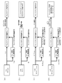
- FIG. 1 it is a schematic diagram which shows the relationship between the state of an action
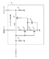
- FIG. 5 It is a circuit diagram which shows the specific structural example of the wakeup stop circuit in the control apparatus for vehicles shown in FIG.
- FIG. 5 is a schematic view for explaining the operation of the wakeup stop circuit shown in FIG. 4;
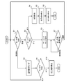
- FIG. 7 is a flowchart showing a control method when the operation switch of the electric parking brake is in the on state and is fixed in the vehicle control device shown in FIG. 1.
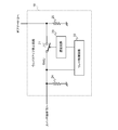
- FIG. 1 is a schematic configuration diagram of a vehicle control device and a vehicle control system.
- an electric parking brake is taken as an example, and a control system for controlling the same and a control system for a vehicle configured with a plurality of control devices connected to the control device via a vehicle-mounted network are shown.
- This system includes a plurality of ECUs (control devices) 2-1, 2-2, 2-3, 2-4,... Connected to one another via CAN buses 1 a and 1 b for in-vehicle network.
- the ECU 2-1 is for the electric parking brake 3 and controls the drive of the actuator 4 that performs braking and release of the electric parking brake 3.
- the ECUs 2-2, 2-3, 2-4,... Use other electric components such as an engine management system, a power train system, a traveling control system, an in-vehicle information system, and various sensors alone or in combination. Control while coordinating or interlocking.
- the ECU 2-1 is a switch (external switch) for operating the CAN communication integrated circuit (IC) 11, the OR gate 12, the wakeup circuit 13, the power supply IC 14, the microcomputer (microcomputer) 15, the wakeup stop circuit 16, and the electric parking brake 3. 17) and so on.
- the ECU 2-1 is provided with a power supply terminal T1, an IGN terminal T2, CAN_H, CAN_L terminals T3 and T4, switch terminals T5 and T6, and the like. Power is supplied to the power supply terminal T1 from the battery BA.
- a signal IGN indicating the state of the ignition key (ignition switch) is input to the IGN terminal T2.
- the CAN_H and CAN_L terminals T3 and T4 are connected to the CAN buses 1a and 1b, respectively.
- the operating switch 17 is connected between the switch terminals T5 and T6.
- the CAN communication IC 11 performs data communication by the CAN protocol from the CAN_H and CAN_L terminals T3 and T4 through the CAN buses 1a and 1b under the control of the microcomputer 15.
- the microcomputer 15 functions as a control unit that controls an electrical component (in this example, the actuator 4 of the electric parking brake 3), and controls reception, transmission, state setting, and the like by the CAN communication IC 11.
- the CAN communication IC 11 outputs the CAN wakeup signal CWU to the OR gate 12.
- the OR gate 12 receives a signal IWU indicating the state of the ignition key from the IGN terminal T2, a wakeup signal SWU corresponding to the on / off state from the operation switch 17, and a self-holding signal SHS from the microcomputer 15.
- the wakeup circuit 13 wakes up the sleep state microcomputer 15 based on the logical product signal output from the OR gate 12. When instructed to wake up, the wakeup circuit 13 supplies power from the power supply terminal T1 to the power supply IC 14 and supplies power from the power supply IC 14 to the microcomputer 15.
- the wakeup circuit 13 is configured by, for example, a semiconductor switch element as illustrated as a P-channel MOSFET 18. The current path of the MOSFET 18 is connected between the power supply terminal T1 and the power supply IC 14.
- the wakeup stop circuit 16 starts timing by using the on operation of the operation switch 17 as a trigger, and functions as a trigger circuit that outputs a wakeup signal SWU that becomes high level for a predetermined time from the trigger. Therefore, even if the operation switch 17 is stuck on, the ECU 2-1 is forcibly stopped (sleep) after a predetermined time has elapsed since the wake-up instruction.
- the microcomputer 15 monitors the signal IGN indicating the state of the ignition key input from the IGN terminal T2, and monitors the wakeup signal SWU input from the switch terminal T6.
- the operating switch 17 is connected between the switch terminals T5 and T6.
- the switch terminal T5 is connected to the power supply terminal T1 via a wire in the ECU 2-1
- the switch terminal T6 is connected to one input terminal of the OR gate 12 via the wakeup stop circuit 16.
- a high level wakeup signal SWU is supplied to the OR gate 12.
- the wakeup signal SWU is cut off by the wakeup stop circuit 16 after a predetermined time has elapsed since the wakeup instruction.
- the operation switch 17 is connected to the power supply terminal T1 via the wiring in the ECU 2-1, it may be directly connected to the vehicle-side power supply line.
- the microcomputer 15 When a high level wakeup signal SWU is input to the OR gate 12, the power is supplied to the microcomputer 15 from the wakeup circuit 13 via the power supply IC 14 to operate, and the microcomputer 15 monitors the state of the operation switch 17 If the electric parking brake is instructed, the actuator 4 is driven via the drive circuit (not shown) to set the electric parking brake 3 in the braking state.
- the microcomputer 15 further outputs a high level self-holding signal SHS to the OR gate 12 to hold the operating state of the ECU 2-1.
- the operation switch 17 instructs the electric parking brake to be released, or, for example, the engine is started and the shift operation or the subsequent accelerator operation is performed. If the electric parking brake 3 is detected, the microcomputer 4 drives the actuator 4 through a drive circuit or the like (not shown) to release the electric parking brake 3.
- FIG. 2 shows the relationship between the state of the operation switch 17 and the operation of the wakeup stop circuit 16 in the above-described vehicle control device.
- the stop of the wakeup function is realized using a one-shot pulse signal.
- the input (wakeup signal SWU) from the operation switch 17 to the ECU 2-1 is a DC high level (DC_Hi), the high impedance state when the operation switch 17 is off, and a steady state of DC low level (DC_Low) It is.
- the wakeup signal SWU is a direct current low level (DC_Low).
- (B) is a case where the operation switch 17 is on for a short time (the pulse width Pw_on of the wakeup signal SWU is shorter than the predetermined time ⁇ T and “Pw_on ⁇ T”). At this time, when the operation switch 17 is turned on, the wakeup stop circuit (trigger circuit) 16 outputs a pulse-like wakeup signal SWU which is high level for a short time Pw_on.
- (C) is a case where the operation switch 17 is on for a long time (when the pulse width Pw_on of the wakeup signal SWU is longer than the predetermined time ⁇ T “Pw_on ⁇ ⁇ T”) or when the on sticking occurs. At this time, when the operation switch 17 is turned on, the trigger circuit outputs a pulse-like wakeup signal SWU which becomes high level for a predetermined time ⁇ T.
- the wakeup function is provided when the activation switch 17 is stuck on by providing the circuit for transferring the wakeup signal SWU shorter than the predetermined time ⁇ T to the inside of the apparatus by using the activation of the activation switch 17 as a trigger. Can be stopped after an arbitrary predetermined time ⁇ T, in other words, a mechanism that wakes up only for an arbitrary time.
- FIG. 3 shows a configuration example of the wakeup stop circuit 16 that realizes the operation as shown in FIG.
- the wakeup stop circuit 16 includes a relay circuit 21, a relay control circuit 22, a delay circuit 23, and resistors 24 and 25 for pull-down.
- the relay circuit 21 interrupts transfer of the wakeup signal SWU input from the operation switch 17 to the OR gate 12 (wakeup circuit 13).
- the relay control circuit 22 detects the on / off operation of the operation switch 17, and instructs the relay circuit 21 to shut off when the switch terminal T6 is high level, and instructs the relay circuit 21 to turn on when the switch terminal T6 is low level.
- the delay circuit 23 delays the output signal of the relay control circuit 22 by a predetermined time ⁇ T.
- the relay circuit 21 is shut off to suppress the wakeup signal SWU from maintaining the high level. Do. This can suppress the wakeup signal SWU from being supplied to the wakeup circuit 13 via the OR gate 12 and maintaining the wakeup state when the on-fixation occurs. Further, the ECU having the CAN wakeup function in the ECUs 2-2, 2-3, 2-4,... Can be suppressed from being woken up due to the on adherence of the operation switch 17.
- the relay circuit 21 is formed of a semiconductor relay (N-channel MOSFET 31), the relay control circuit 22 and the delay circuit 23 are P-channel MOSFET 32, N-channel MOSFET 33. , Resistors 34 and 35 and a capacitor 36.
- the current path of the MOSFET 31 is connected between the switch terminal T 6 and one input terminal of the OR gate 12.
- the resistor 34, the current path of the MOSFET 32, and the current path of the resistor 35 and the MOSFET 33 are connected in series between the power supply terminal T1 and the ground point, and the gates of the MOSFETs 32 and 33 are connected to the switch terminal T6.
- the gate of the MOSFET 31 is connected to the connection point of the MOSFET 32 and the resistor 35, and the capacitor 36 is connected between this connection point and the ground point.
- the MOSFETs 32, 33 have a CMOS inverter configuration for controlling the MOSFET 31 based on the switch terminal T6, that is, the on / off operation of the operation switch 17.
- the resistor 35 and the capacitor 36 generate a time constant to delay the inversion operation from the high level output state of the CMOS inverter to the low level output state.
- FIG. 5 shows in detail the relationship between the level of the wakeup signal SWU (level of the switch terminal T6) input to the wakeup stop circuit 16 shown in FIG. 4 and the signal input to the OR gate 12.
- A has shown the case where the low level (DC_Low) of direct current
- the relay control and delay circuit MOSFETs 32, 33, resistors 34, 35 and capacitor 36
- a wakeup signal passage permission is issued to the wakeup signal cutoff relay (MOSFET 31).
- a low level signal passes through the relay, and a low level wakeup signal SWU is supplied to the OR gate 12.
- (C) shows the case where the signal input from the switch terminal T6 changes from the direct current high level (DC_Hi) to the direct current low level (DC_Low).
- DC_Hi direct current high level
- DC_Low direct current low level
- a wakeup signal cutoff instruction is issued to the wakeup signal cutoff relay, and passage permission is issued after a predetermined time ⁇ T elapses. Therefore, the signal is cut off by the relay and the wakeup signal SWU becomes low level, and the switch terminal T6 is low level even if passage is permitted after the predetermined time ⁇ T elapses, the wakeup signal SWU maintains low level.
- (D) shows the case where the signal input from the switch terminal T6 changes from the low level of direct current (DC_Low) to the high level of direct current (DC_Hi).
- DC_Low low level of direct current
- DC_Hi high level of direct current
- the relay control and delay circuit is configured by the CMOS inverter circuit and the RC circuit, and the wakeup signal cutoff relay is configured by the N-channel type MOSFET
- a high level signal is input to the switch terminal T6
- a relay cut-off instruction is issued to the switch, and when a low level signal is input, an instruction to turn on the relay can be issued.
- the relay shutoff instruction is issued after a predetermined time ⁇ T has elapsed from relay on, due to the delay time of the RC circuit.
- the dark current is on the order of nA.
- the trigger by the rising edge can be changed to the trigger by the falling edge by changing the blocking relay to a P-channel MOSFET and the pull-down resistor to a pull-up resistor.
- the present invention is also applicable to the case where the operation switch 17 is grounded instead of being connected to the battery power.
- the microcomputer 15 diagnoses whether or not the operation switch 17 of the electric parking brake 3 is stuck on (step S1).
- the diagnosis of the on adherence of the operation switch 17 monitors the wakeup signal SWU (the level of the switch terminal T6) of the ECU 2-1 which controls the electric parking brake 3 by the microcomputer 15, and the wakeup signal SWU is high level for a predetermined time. When continuing, it is determined as on-sticking.
- the on / off determination of the ignition key is performed (step S2).
- the on / off determination of the ignition key is performed by monitoring the signal IGN input from the IGN terminal T2 by the microcomputer 15.
- step S3 When it is determined that the ignition key is turned on, for example, a warning lamp is turned on to notify the driver and draw attention (step S3).
- step S3 if it is determined that the vehicle is off, that is, if the operation switch 17 of the electric parking brake 3 in the ECU 2-1 is stuck on and the ignition key is off, the driver is notified of a failure at restart.
- failure recording is performed on a storage device (not shown) in the ECU 2-1 (step S4).
- step S5 the self-holding is stopped
- step S6 the operation is stopped.
- step S8 When it is determined in step S1 that the on-fixation does not occur, the normal operation mode is set (step S8). In the normal operation mode, it is possible to transmit and receive data by the CAN protocol. Next, it is determined whether the ignition key is on or off (step S9). If the switch is on, the process moves to step S1 to repeat the above-described operation. If the switch is off, the microcomputer 15 stops (sleeps) the operation of the ECU 2-1 and ends the process.
- the wakeup stop circuit 16 forcibly shuts off the wakeup signal SWU after a predetermined time has elapsed from the wakeup instruction. Therefore, even if the operation switch 17 is stuck in the on state, the ECU 2-1 can be put to sleep. Therefore, the dark current when the ignition is off can be reduced.
- the ECU 2-1 and other electric components with the operation switch 17 fixed in the on state Communication with the product ECUs 2-2, 2-3, 2-4, ... is performed, and the ECUs for other electrical components having a wakeup function continue to operate and cause an increase in current consumption. Absent. Therefore, it is also possible to suppress the occurrence of the battery exhaustion after the on-fixation of the operation switch 17 continues.
- the vehicle control device including the ECU for controlling the electric parking brake has been described as an example, but the present invention is not limited to the embodiment described above, and a range not departing from the gist It is possible to carry out various modifications.
- the present invention is also applicable to a door switch that turns on / off in conjunction with the opening and closing of the door. Even if the room lamp and the warning buzzer are activated in conjunction with the opening and closing of the door, the driver will stop moving without notice to the half door by continuing the operation for a predetermined time and then forcibly stopping the operation. Can also suppress battery drain. In addition, when there is an ECU or a circuit interlocked with the door switch, these operations may be continued for a predetermined time and then forcibly stopped.
- 1a, 1b CAN bus, 2-1, 2-2, 2-3, 2-4: ECU (control device), 3: electric parking brake (electric component), 4: actuator, 11: CAN communication IC, 12 ... OR gate, 13 ... wake up circuit, 14 ... power supply IC, 15 ... microcomputer (control section), 16 ... wake up stop circuit, 17 ... operation switch (external switch), 21 ... relay circuit, 22 ... relay control circuit, 23 ... delay circuit, SWU ... wakeup signal, ⁇ T ... predetermined time
Landscapes
- Engineering & Computer Science (AREA)
- Mechanical Engineering (AREA)
- Transportation (AREA)
- Automation & Control Theory (AREA)
- Physics & Mathematics (AREA)
- General Physics & Mathematics (AREA)
- Computer Networks & Wireless Communication (AREA)
- Signal Processing (AREA)
- Regulating Braking Force (AREA)
- Combined Controls Of Internal Combustion Engines (AREA)
Abstract
車両用制御装置は、電装品を制御する制御部と、電装品を作動させるスイッチからのウェイクアップ信号に基づいて制御部をウェイクアップさせるウェイクアップ回路と、スイッチからウェイクアップ回路へ供給されるウェイクアップ信号を、ウェイクアップの指示から所定時間経過後に遮断するウェイクアップ停止回路とを備える。ウェイクアップの指示から所定時間経過後にスイッチの状態に拘わらず、ウェイクアップ停止回路でウェイクアップ信号を強制的に遮断して当該車両用制御装置をスリープさせるので、スイッチがオン状態で固着してもウェイクアップ状態が維持されるのを抑制できる。
Description
本発明は、電装品を制御する車両用制御装置及びその制御方法、並びに車両用制御装置がcontroller area network(CAN)などの車載ネットワークで接続された車両用制御システムに関する。
車両に搭載されたelectronic control unit(ECU)で制御される電装品は多種にわたっており、様々な制御が行われている。例えば特許文献1には、ECUで制御される電動パーキングブレーキ装置が開示されている。この特許文献1では、イグニッション電源がオンで且つエンジンが停止中に、スロットル操作及びシフト操作に連動したパーキングブレーキの自動的な解除を禁止することによって、誤操作を抑制して安全性を向上させている。
ところで、近年は車両の電装化が進み、1車両当たりのECUの搭載数が増加している。多数のECUを搭載した車両用制御装置では、イグニッションオフ時の暗電流が増大するため、暗電流の低減要求が強くなっている。
しかしながら、上述した電動パーキングブレーキにあっては、作動スイッチがオン状態で固着する(オン固着と称する)と、ウェイクアップ信号がハイレベルに固定され、電動パーキングブレーキ用のECUを動作停止(スリープ)状態にできない虞がある。
しかしながら、上述した電動パーキングブレーキにあっては、作動スイッチがオン状態で固着する(オン固着と称する)と、ウェイクアップ信号がハイレベルに固定され、電動パーキングブレーキ用のECUを動作停止(スリープ)状態にできない虞がある。
このため、イグニッションオフ時にも、当該ECUと他の電装品用のECUとのCAN通信が行われ、CANウェイクアップ機能を有する他の電装品用のECUが動作継続状態となって消費電流の増加を招く。作動スイッチのオン固着が長く続くと、バッテリ上がりが起こることになる。
この問題は、電動パーキングブレーキに限らず、車載ネットワークで接続された複数のECUを備える車両用制御システムにおいて、電装品を作動させるスイッチがオン状態で固着すると発生する。
この問題は、電動パーキングブレーキに限らず、車載ネットワークで接続された複数のECUを備える車両用制御システムにおいて、電装品を作動させるスイッチがオン状態で固着すると発生する。
本発明は上記のような事情に鑑みてなされたもので、その目的とするところは、電装品を作動させるスイッチがオン状態で固着した場合に、イグニッションオフ時の暗電流を低減できる車両用制御装置及びその制御方法、並びに車両用制御システムを提供することにある。
本発明の車両用制御装置は、電装品を制御する制御部と、前記電装品を作動させるスイッチからのウェイクアップ信号に基づいて前記制御部をウェイクアップさせるウェイクアップ回路と、前記スイッチから前記ウェイクアップ回路へ供給されるウェイクアップ信号を、ウェイクアップの指示から所定時間経過後に遮断するウェイクアップ停止回路とを具備する、ことを特徴とする。
また、本発明の車両用制御装置の制御方法は、電装品を制御する制御部と、前記電装品を作動させるスイッチからのウェイクアップ信号に基づいて前記制御部をウェイクアップさせるウェイクアップ回路と、前記スイッチから前記ウェイクアップ回路へ供給されるウェイクアップ信号を、ウェイクアップの指示から所定時間経過後に遮断するウェイクアップ停止回路と備える車両用制御装置の制御方法であって、前記制御部における電装品を作動させるスイッチがオン状態で固着しているか否か診断すること、前記スイッチがオン状態で固着していると診断されたときに、イグニッションキーのオン/オフ判定を行うこと、前記イグニッションキーがオフと判定された場合に故障記録を行うこと、及び自己保持を停止し、スリープさせて動作を停止すること、を具備することを特徴とする。
更に、本発明の車両用制御システムは、複数の電装品をそれぞれ制御する複数の制御装置が車載ネットワークで接続された車両用制御システムであって、前記複数の制御装置の少なくとも1つは、電装品を作動するスイッチに応答してウェイクアップし、所定時間経過後に前記スイッチの状態に拘わらずウェイクアップを停止する、ことを特徴とする。
本発明によれば、ウェイクアップ停止回路で、ウェイクアップ信号を、ウェイクアップの指示から所定時間経過後に遮断するので、スイッチがオン状態で固着してもウェイクアップ状態を強制的に停止させることができる。従って、電装品を作動させるスイッチがオン状態で固着してもウェイクアップ状態が維持されることはなく、イグニッションオフ時の暗電流を低減できる。
また、この車両用制御装置が含まれる複数の制御装置が車載ネットワークで接続された車両用制御システムにおいて、電装品を作動させるスイッチがオン状態で固着した車両用制御装置と他の電装品用の車両用制御装置との通信が行われ、ウェイクアップ機能を有する他の電装品用の車両用制御装置が動作継続状態となって消費電流の増加を招くこともない。よって、電装品を作動させるスイッチのオン固着が続いてバッテリ上がりが起こるのも抑制できる。
以下、本発明の実施形態について図面を参照して説明する。
図1は、車両用制御装置及び車両用制御システムの概略構成図である。制御対象の電装品として電動パーキングブレーキを例に取り、これを制御する制御装置と、この制御装置に車載ネットワークで接続された複数の制御装置で構成された車両用制御システムを示している。
図1は、車両用制御装置及び車両用制御システムの概略構成図である。制御対象の電装品として電動パーキングブレーキを例に取り、これを制御する制御装置と、この制御装置に車載ネットワークで接続された複数の制御装置で構成された車両用制御システムを示している。
このシステムは、車載ネットワーク用のCANバス1a,1bを介して相互に接続された複数のECU(制御装置)2-1,2-2,2-3,2-4,…を備えている。ECU2-1は、電動パーキングブレーキ3用であり、電動パーキングブレーキ3の制動と解除を行うアクチュエータ4の駆動を制御する。ECU2-2,2-3,2-4,…は、他の電装品、例えばエンジンマネジメント系、パワートレイン系、走行制御系及び車載情報系などの装置や各種センサ類を、それぞれ単独または複数で協調あるいは連動しつつ制御する。
ECU2-1は、CAN通信integrated circuit(IC)11、オアゲート12、ウェイクアップ回路13、電源IC14、マイクロコンピュータ(マイコン)15、ウェイクアップ停止回路16、及び電動パーキングブレーキ3を作動させるスイッチ(外部スイッチ)17などを含んで構成される。このECU2-1には、電源端子T1、IGN端子T2、CAN_H,CAN_L端子T3,T4、スイッチ端子T5,T6などが設けられている。電源端子T1には、バッテリBAから電源が供給される。IGN端子T2には、イグニッションキー(イグニッションスイッチ)の状態を示す信号IGNが入力される。CAN_H,CAN_L端子T3,T4は、CANバス1a,1bにそれぞれ接続される。スイッチ端子T5,T6間には、作動スイッチ17が接続される。
CAN通信IC11には、電源端子T1から電源が供給される。CAN通信IC11は、マイクロコンピュータ15の制御により、CAN_H,CAN_L端子T3,T4からCANバス1a,1bを介してCANプロトコルによるデータ通信を行う。マイクロコンピュータ15は、電装品(本例では電動パーキングブレーキ3のアクチュエータ4)を制御する制御部として機能するものであり、CAN通信IC11による受信、送信及びステート設定などを制御する。そして、CAN通信IC11からオアゲート12にCANウェイクアップ信号CWUを出力する。オアゲート12には、IGN端子T2からイグニッションキーの状態を示す信号IWU、作動スイッチ17からオン/オフ状態に応じたウェイクアップ信号SWU、及びマイクロコンピュータ15から自己保持信号SHSなどが入力される。
ウェイクアップ回路13は、オアゲート12から出力される論理積信号に基づいて、スリープ状態のマイクロコンピュータ15をウェイクアップさせるものである。ウェイクアップ回路13は、ウェイクアップが指示されると、電源端子T1から電源IC14に電源を供給し、この電源IC14からマイクロコンピュータ15に電源を供給するようになっている。ウェイクアップ回路13は、例えば、Pチャネル型MOSFET18として図に示した様な半導体スイッチ素子で構成される。MOSFET18の電流通路は、電源端子T1と電源IC14間に接続される。ウェイクアップ停止回路16は、作動スイッチ17のオン動作をトリガにして計時を開始し、トリガから所定時間ハイレベルとなるウェイクアップ信号SWUを出力するトリガ回路として機能する。よって、作動スイッチ17がオン固着しても、ウェイクアップの指示から所定時間経過後にECU2-1を強制的に動作停止(スリープ)させる。
マイクロコンピュータ15は、IGN端子T2から入力されるイグニッションキーの状態を示す信号IGNをモニタすると共に、スイッチ端子T6から入力されるウェイクアップ信号SWUをモニタする。作動スイッチ17は、スイッチ端子T5,T6間に接続される。スイッチ端子T5は、ECU2-1内の配線を介して電源端子T1に接続され、スイッチ端子T6は、ウェイクアップ停止回路16を介してオアゲート12の1つの入力端子に接続されている。スリープ状態で作動スイッチ17がオン状態になると、オアゲート12にハイレベルのウェイクアップ信号SWUが供給される。このウェイクアップ信号SWUは、ウェイクアップ停止回路16によって、ウェイクアップの指示から所定時間経過後に遮断される。
ここでは、作動スイッチ17をECU2-1内の配線を介して電源端子T1に接続したが、車両側の電源線に直接接続しても良い。
ここでは、作動スイッチ17をECU2-1内の配線を介して電源端子T1に接続したが、車両側の電源線に直接接続しても良い。
オアゲート12にハイレベルのウェイクアップ信号SWUが入力されると、ウェイクアップ回路13から電源IC14を介して、マイクロコンピュータ15に電源が供給されて稼働し、マイクロコンピュータ15で作動スイッチ17の状態をモニタし、電動パーキングブレーキ制動を指示していれば、駆動回路等(図示せず)を介して、アクチュエータ4を駆動して電動パーキングブレーキ3を制動状態に設定する。マイクロコンピュータ15は、更にオアゲート12にハイレベルの自己保持信号SHSを出力してECU2-1の作動状態を保持する。
電動パーキングブレーキ3が制動状態で、且つイグニッションキーがオン状態において、作動スイッチ17が電動パーキングブレーキ解除を指示した場合、あるいは例えばエンジンが起動されてシフト操作またはその後のアクセル操作が行われたことを検出した場合には、マイクロコンピュータ15で駆動回路等(図示せず)を介して、アクチュエータ4を駆動して電動パーキングブレーキ3を解除する。
電動パーキングブレーキ3が制動状態で、且つイグニッションキーがオン状態において、作動スイッチ17が電動パーキングブレーキ解除を指示した場合、あるいは例えばエンジンが起動されてシフト操作またはその後のアクセル操作が行われたことを検出した場合には、マイクロコンピュータ15で駆動回路等(図示せず)を介して、アクチュエータ4を駆動して電動パーキングブレーキ3を解除する。
図2は、上述した車両用制御装置において、作動スイッチ17の状態とウェイクアップ停止回路16の動作との関係を示している。本例は、ワンショットパルス信号を用いてウェイクアップ機能の停止を実現するものである。
(a)は作動スイッチ17からECU2-1への入力(ウェイクアップ信号SWU)が、直流のハイレベル(DC_Hi)、作動スイッチ17がオフでハイインピーダンス状態、及び直流のロウレベル(DC_Low)の定常状態である。このときには、ウェイクアップ信号SWUは、直流のロウレベル(DC_Low)となる。
(a)は作動スイッチ17からECU2-1への入力(ウェイクアップ信号SWU)が、直流のハイレベル(DC_Hi)、作動スイッチ17がオフでハイインピーダンス状態、及び直流のロウレベル(DC_Low)の定常状態である。このときには、ウェイクアップ信号SWUは、直流のロウレベル(DC_Low)となる。
(b)は作動スイッチ17が短時間オン(ウェイクアップ信号SWUのパルス幅Pw_onが所定時間ΔTより短く「Pw_on<ΔT」)の場合である。このときには、作動スイッチ17のオンによって、ウェイクアップ停止回路(トリガ回路)16から短時間Pw_onだけハイレベルとなるパルス状のウェイクアップ信号SWUが出力される。
(c)は作動スイッチ17が長時間オン(ウェイクアップ信号SWUのパルス幅Pw_onが所定時間ΔTより長く「Pw_on≧ΔT」)の場合、あるいはオン固着が発生した場合である。このときには、作動スイッチ17のオンによって、トリガ回路から所定時間ΔTだけハイレベルとなるパルス状のウェイクアップ信号SWUが出力される。
(c)は作動スイッチ17が長時間オン(ウェイクアップ信号SWUのパルス幅Pw_onが所定時間ΔTより長く「Pw_on≧ΔT」)の場合、あるいはオン固着が発生した場合である。このときには、作動スイッチ17のオンによって、トリガ回路から所定時間ΔTだけハイレベルとなるパルス状のウェイクアップ信号SWUが出力される。
上述したように、作動スイッチ17のオン動作をトリガとし、所定時間ΔTより短いウェイクアップ信号SWUを装置内部へ転送する回路を設けたことで、作動スイッチ17がオン固着した場合に、ウェイクアップ機能を任意の所定時間ΔT後に停止できる機構、換言すれば任意時間のみウェイクアップさせる機構を実現できる。
図3は、図2に示したような動作を実現するウェイクアップ停止回路16の構成例を示している。このウェイクアップ停止回路16は、リレー回路21、リレー制御回路22、遅延回路23及びプルダウン用の抵抗器24,25などを含んで構成される。リレー回路21は、作動スイッチ17から入力されるウェイクアップ信号SWUのオアゲート12(ウェイクアップ回路13)への転送を遮断する。リレー制御回路22は、作動スイッチ17のオン/オフ動作を検出するもので、スイッチ端子T6がハイレベルのときにリレー回路21の遮断を指示し、ロウレベルのときにリレー回路21のオンを指示する。遅延回路23は、リレー制御回路22の出力信号を所定時間ΔTだけ遅延するものである。
このようにすることで、ウェイクアップ信号SWUが遅延回路23の遅延時間よりも長い時間ハイレベルになったときに、リレー回路21を遮断してウェイクアップ信号SWUがハイレベルを維持するのを抑制する。これによって、オン固着が発生した場合に、ウェイクアップ信号SWUがオアゲート12を介してウェイクアップ回路13に供給されてウェイクアップ状態が維持されるのを抑制できる。また、ECU2-2,2-3,2-4,…の中のCANウェイクアップ機能を有するECUが、作動スイッチ17のオン固着により、ウェイクアップされるのも抑制できる。
図4は、図3に示したウェイクアップ停止回路16において、リレー回路21を半導体リレー(Nチャネル型MOSFET31)で形成し、リレー制御回路22と遅延回路23をPチャネル型MOSFET32、Nチャネル型MOSFET33、抵抗器34,35及びキャパシタ36で形成している。
MOSFET31の電流通路は、スイッチ端子T6とオアゲート12の1つの入力端子間に接続される。電源端子T1と接地点間には、抵抗器34、MOSFET32の電流通路、抵抗器35及びMOSFET33の電流通路が直列接続され、MOSFET32,33のゲートがスイッチ端子T6に接続される。MOSFET32と抵抗器35の接続点には、MOSFET31のゲートが接続されると共に、この接続点と接地点間にキャパシタ36が接続されている。
MOSFET31の電流通路は、スイッチ端子T6とオアゲート12の1つの入力端子間に接続される。電源端子T1と接地点間には、抵抗器34、MOSFET32の電流通路、抵抗器35及びMOSFET33の電流通路が直列接続され、MOSFET32,33のゲートがスイッチ端子T6に接続される。MOSFET32と抵抗器35の接続点には、MOSFET31のゲートが接続されると共に、この接続点と接地点間にキャパシタ36が接続されている。
MOSFET32,33はスイッチ端子T6、すなわち作動スイッチ17のオン/オフ動作に基づいてMOSFET31を制御するCMOSインバータ構成になっている。抵抗器35とキャパシタ36は時定数を生成し、CMOSインバータのハイレベルの出力状態からロウレベルの出力状態への反転動作を遅延するようになっている。これによって、スイッチ端子T6のウェイクアップ信号SWUがロウレベルのときにはMOSFET31はオン状態となる。しかし、スイッチ端子T6はロウレベルであるので、ウェイクアップ信号SWUがロウレベルである。一方、ウェイクアップ信号SWUがハイレベルになると、この信号SWUがMOSFET31を介してオアゲート12に転送され、抵抗器35とキャパシタ36の時定数による所定時間ΔT経過後にMOSFET31はオフ状態となる。従って、オアゲート12には所定時間ΔTだけハイレベルとなるパルス状のウェイクアップ信号SWUが供給される。
図5は、図4に示したウェイクアップ停止回路16に入力されるウェイクアップ信号SWUのレベル(スイッチ端子T6のレベル)と、オアゲート12に入力される信号との関係を詳細に示している。(a)は、スイッチ端子T6から直流のロウレベル(DC_Low)が入力された場合を示している。リレー制御及び遅延回路(MOSFET32,33、抵抗器34,35及びキャパシタ36)にロウレベルの信号が入力されると、ウェイクアップ信号遮断リレー(MOSFET31)にウェイクアップ信号通過許可が出される。これによって、リレーをロウレベルの信号が通過し、ロウレベルのウェイクアップ信号SWUがオアゲート12に供給される。
(b)は、スイッチ端子T6から直流のハイレベル(DC_Hi)が入力された場合を示している。リレー制御及び遅延回路にハイレベルの信号が入力されると、ウェイクアップ信号遮断リレーにウェイクアップ信号遮断指示が出される。これによって、リレーで信号が遮断され、ウェイクプルダウンによりウェイクアップ信号SWUはロウレベルとなる。
(c)は、スイッチ端子T6から入力される信号が直流のハイレベル(DC_Hi)から直流のロウレベル(DC_Low)に変化した場合を示している。リレー制御及び遅延回路にハイレベルからロウレベルに変化する信号が入力されると、ウェイクアップ信号遮断リレーにウェイクアップ信号遮断指示が出され、所定時間ΔT経過後に通過許可が出される。従って、リレーで信号が遮断されてウェイクアップ信号SWUはロウレベルとなり、所定時間ΔT経過後に通過許可になっても、スイッチ端子T6がロウレベルであるので、ウェイクアップ信号SWUはロウレベルを維持する。
(d)は、スイッチ端子T6から入力される信号が直流のロウレベル(DC_Low)から直流のハイレベル(DC_Hi)に変化した場合を示している。リレー制御及び遅延回路にロウレベルからハイレベルに変化する信号が入力されると、ウェイクアップ信号遮断リレーにウェイクアップ信号通過許可が出され、所定時間ΔT経過後に遮断指示が出される。従って、ウェイクアップ信号SWUは、所定時間ΔTだけパルス状にハイレベルとなる。
上述したように、リレー制御及び遅延回路をCMOSインバータ回路とRC回路で構成し、ウェイクアップ信号遮断リレーをNチャネル型MOSFETで構成することにより、スイッチ端子T6にハイレベルの信号が入力された場合にはリレー遮断指示が出され、ロウレベルの信号が入力された場合にはリレーオンの指示を出すことができる。リレー遮断指示は、RC回路の遅延時間によって、リレーオンから所定時間ΔT経過後に出されることになる。
上記構成では、ECU2-1の動作停止時(作動スイッチオフ、信号IGNでイグニッションキーがオフ状態)には、各MOSFETのゲートリーク電流とオフリーク電流のみしか電流パスがないので、暗電流の増加を最小限に抑制できる。具体的には、暗電流はnAオーダー程度になる。
なお、図4に示した回路において、遮断リレーをPチャネル型MOSFETに、プルダウン抵抗器をプルアップ抵抗器に変更することで、立ち上がりエッジによるトリガから、立ち下がりエッジによるトリガに変更することができる。これによって、作動スイッチ17をバッテリ電源に接続するのではなく、接地する場合にも適用可能である。
次に、上記のような構成において、図6のフローチャートにより電動パーキングブレーキを作動するスイッチがオン状態で固着した場合の制御方法を説明する。まず、マイクロコンピュータ15で、電動パーキングブレーキ3の作動スイッチ17のオン固着の有無の診断を行う(ステップS1)。作動スイッチ17のオン固着の診断は、マイクロコンピュータ15で電動パーキングブレーキ3を制御するECU2-1のウェイクアップ信号SWU(スイッチ端子T6のレベル)をモニタし、ウェイクアップ信号SWUが所定時間ハイレベルを継続したときにオン固着と判定する。オン固着と診断すると、イグニッションキーのオン/オフ判定を行う(ステップS2)。イグニッションキーのオン/オフ判定は、マイクロコンピュータ15でIGN端子T2から入力される信号IGNをモニタすることで行う。
イグニッションキーがオンと判定されると、運転者に報知して注意を促すために、例えばワーニングランプを点灯する(ステップS3)。一方、オフと判定された場合、すなわちECU2-1における電動パーキングブレーキ3の作動スイッチ17がオン固着し、且つイグニッションキーがオフの場合には、再起動時に運転者に故障があったことを知らせるために、ECU2-1内の記憶装置(図示せず)に故障記録を行う(ステップS4)。次に、自己保持を停止し(ステップS5)、ECU2-1をスリープさせて動作を停止する(ステップS6)。これによって、ECU2-2,2-3,2-4,…の中のCANウェイクアップ機能を有するECUが、電動パーキングブレーキ3の作動スイッチ17のオン固着により、ウェイクアップされるのを抑制する。従って、エンジン停止後も作動が必要なECUを除く、車両内の全てのECU2-1,2-2,2-3,2-4,…の動作を停止させることができ、暗電流を低減できる。
ステップS1で、オン固着無しと判定された場合には、通常動作モードとなる(ステップS8)。通常動作モードでは、CANプロトコルによるデータの送受信が可能になっている。次に、イグニッションキーのオン/オフ判定を行う(ステップS9)。そして、オンであればステップS1に移動して上述した動作を繰り返し、オフであればマイクロコンピュータ15により当該ECU2-1の動作を停止(スリープ)して終了する。
上記のような構成によれば、電動パーキングブレーキ3の作動スイッチ17がオン固着した場合に、ウェイクアップ停止回路16で、ウェイクアップの指示から所定時間経過後に、ウェイクアップ信号SWUを強制的に遮断するので、作動スイッチ17がオン状態で固着してもECU2-1をスリープさせることができる。従って、イグニッションオフ時の暗電流を低減できる。
また、このECU2-1が含まれる複数のECU2-2,2-3,2-4,…が車載ネットワークで接続されたシステムにおいて、作動スイッチ17がオン状態で固着したECU2-1と他の電装品用のECU2-2,2-3,2-4,…との通信が行われ、ウェイクアップ機能を有する他の電装品用のECUが動作継続状態となって消費電流の増加を招くこともない。よって、作動スイッチ17のオン固着が続いてバッテリ上がりが起こるのも抑制できる。
なお、上述した実施形態では、電動パーキングブレーキを制御するECUを含む車両用制御装置を例に取って説明したが、本発明は上述した実施形態に限定されるものではなく、要旨を逸脱しない範囲で種々変形して実施することが可能である。
[変形例]
例えばドアの開閉に連動してオン/オフするドアスイッチにも適用可能である。ドアの開閉に連動してルームランプや警告ブザーなどが作動しても、所定時間動作を継続させた後強制的に停止させることで、運転者が半ドアに気づかずに降車して放置した場合にもバッテリ上がりを抑制できる。
また、ドアスイッチと連動するECUや回路がある場合には、これらの動作を所定時間継続させた後、強制的に停止させるようにしても良い。
例えばドアの開閉に連動してオン/オフするドアスイッチにも適用可能である。ドアの開閉に連動してルームランプや警告ブザーなどが作動しても、所定時間動作を継続させた後強制的に停止させることで、運転者が半ドアに気づかずに降車して放置した場合にもバッテリ上がりを抑制できる。
また、ドアスイッチと連動するECUや回路がある場合には、これらの動作を所定時間継続させた後、強制的に停止させるようにしても良い。
1a,1b…CANバス、2-1,2-2,2-3,2-4…ECU(制御装置)、3…電動パーキングブレーキ(電装品)、4…アクチュエータ、11…CAN通信IC、12…オアゲート、13…ウェイクアップ回路、14…電源IC、15…マイクロコンピュータ(制御部)、16…ウェイクアップ停止回路、17…作動スイッチ(外部スイッチ)、21…リレー回路、22…リレー制御回路、23…遅延回路、SWU…ウェイクアップ信号、ΔT…所定時間
Claims (19)
- 電装品を制御する制御部と、前記電装品を作動させるスイッチからのウェイクアップ信号に基づいて前記制御部をウェイクアップさせるウェイクアップ回路と、前記スイッチから前記ウェイクアップ回路へ供給されるウェイクアップ信号を、ウェイクアップの指示から所定時間経過後に遮断するウェイクアップ停止回路とを具備する、ことを特徴とする車両用制御装置。
- 前記ウェイクアップ停止回路は、前記スイッチのオン動作をトリガにして計時を開始し、トリガから所定時間前記ウェイクアップ信号を転送するトリガ回路を含む、ことを特徴とする請求項1に記載の車両用制御装置。
- 前記トリガ回路は、前記スイッチから前記ウェイクアップ回路へのウェイクアップ信号を遮断するリレー回路と、前記スイッチのオン/オフ動作を検出して前記リレー回路を制御するリレー制御回路と、前記リレー制御回路により制御され、前記スイッチのオン状態を検出してから所定時間経過するまで前記リレー回路をオンさせる遅延回路とを含む、ことを特徴とする請求項2に記載の車両用制御装置。
- 前記電装品は、電動パーキングブレーキである、ことを特徴とする請求項1に記載の車両用制御装置。
- 前記制御部は、マイクロコンピュータを含む、ことを特徴とする請求項1に記載の車両用制御装置。
- CAN通信integrated circuit(IC)と、オアゲートと、電源ICとを更に具備する、ことを特徴とする請求項5に記載の車両用制御装置。
- 前記CAN通信ICは、CANバスを介して他の電装品を制御する制御装置とデータ通信を行う、ことを特徴とする請求項6に記載の車両用制御装置。
- 前記オアゲートは、前記CAN通信ICから出力されるCANウェイクアップ信号、イグニッションキーの状態を示す信号、前記スイッチの状態に連動するウェイクアップ信号、及び前記マイクロコンピュータから自己保持信号が入力され、前記ウェイクアップ回路を制御する、ことを特徴とする請求項7に記載の車両用制御装置。
- 前記ウェイクアップ回路は、前記オアゲートの出力信号に基づき、前記電源ICから前記マイクロコンピュータに電源を供給して前記マイクロコンピュータをスリープ状態からウェイクアップさせる、ことを特徴とする請求項8に記載の車両用制御装置。
- 前記ウェイクアップ回路は、電流通路が電源端子と前記電源IC間に接続され、前記オアゲートの出力信号に基づきオン/オフ制御される半導体スイッチ素子を含む、ことを特徴とする請求項9に記載の車両用制御装置。
- 前記電装品は、電動パーキングブレーキであり、
前記マイクロコンピュータは、前記スイッチの状態をモニタし、当該スイッチが電動パーキングブレーキの制動を指示していれば、前記電動パーキングブレーキを制動状態に設定する、ことを特徴とする請求項10に記載の車両用制御装置。 - 電装品を制御する制御部と、前記電装品を作動させるスイッチからのウェイクアップ信号に基づいて前記制御部をウェイクアップさせるウェイクアップ回路と、前記スイッチから前記ウェイクアップ回路へ供給されるウェイクアップ信号を、ウェイクアップの指示から所定時間経過後に遮断するウェイクアップ停止回路と備える車両用制御装置の制御方法であって、
前記制御部における電装品を作動させるスイッチがオン状態で固着しているか否か診断すること、
前記スイッチがオン状態で固着していると診断されたときに、イグニッションキーのオン/オフ判定を行うこと、
前記イグニッションキーがオフと判定された場合に故障記録を行うこと、及び
自己保持を停止し、スリープさせて動作を停止すること、
を具備することを特徴とする車両用制御装置の制御方法。 - 前記イグニッションキーがオンと判定された場合に、車両の運転者に報知すること、を更に備えることを特徴とする請求項12に記載の車両用制御装置の制御方法。
- 前記車両の運転者に報知することは、ワーニングランプを点灯すること、であることを特徴とする請求項13に記載の車両用制御装置の制御方法。
- 前記車両の運転者に報知することの後に、前記スイッチがオン状態で固着している状態から復帰したか否かの復帰診断を行うこと、を更に備えることを特徴とする請求項14に記載の車両用制御装置の制御方法。
- 複数の電装品をそれぞれ制御する複数の制御装置が車載ネットワークで接続された車両用制御システムであって、
前記複数の制御装置の少なくとも1つは、電装品を作動するスイッチに応答してウェイクアップし、所定時間経過後に前記スイッチの状態に拘わらずウェイクアップを停止する、ことを特徴とする車両用制御システム。 - 前記複数の制御装置はそれぞれelectronic control unit(ECU)であり、前記車載ネットワークはcontroller area network(CAN)である、ことを特徴とする請求項16に記載の車両用制御システム。
- 前記複数の制御装置の少なくとも1つは、電装品を制御する制御部と、前記電装品を作動させるスイッチからのウェイクアップ信号に基づいて前記制御部をウェイクアップさせるウェイクアップ回路と、前記スイッチから前記ウェイクアップ回路へ供給されるウェイクアップ信号を、ウェイクアップの指示から所定時間経過後に遮断するウェイクアップ停止回路とを具備する、ことを特徴とする請求項16に記載の車両用制御システム。
- 前記ウェイクアップ回路は、前記電装品を作動させるスイッチからのウェイクアップ信号に加えて、他の電装品を制御する制御装置から前記車載ネットワークを介して受信した他の制御装置のウェイクアップ信号に基づいて前記制御部を動作させる、ことを特徴とする請求項18に記載の車両用制御システム。
Priority Applications (3)
| Application Number | Priority Date | Filing Date | Title |
|---|---|---|---|
| CN201680016142.4A CN107406047B (zh) | 2015-03-17 | 2016-02-19 | 车辆用控制装置及其控制方法、以及车辆用控制系统 |
| US15/557,279 US10501081B2 (en) | 2015-03-17 | 2016-02-19 | Vehicular control device, method of controlling vehicular control device, and vehicular control system |
| DE112016001253.5T DE112016001253B4 (de) | 2015-03-17 | 2016-02-19 | Fahrzeugsteuereinrichtung, verfahren zum steuern einer fahrzeugsteuereinrichtung und fahrzeugsteuersystem |
Applications Claiming Priority (2)
| Application Number | Priority Date | Filing Date | Title |
|---|---|---|---|
| JP2015-053628 | 2015-03-17 | ||
| JP2015053628A JP6417249B2 (ja) | 2015-03-17 | 2015-03-17 | 車両用制御装置及び車両用制御システム |
Publications (1)
| Publication Number | Publication Date |
|---|---|
| WO2016147794A1 true WO2016147794A1 (ja) | 2016-09-22 |
Family
ID=56918906
Family Applications (1)
| Application Number | Title | Priority Date | Filing Date |
|---|---|---|---|
| PCT/JP2016/054888 Ceased WO2016147794A1 (ja) | 2015-03-17 | 2016-02-19 | 車両用制御装置及びその制御方法、並びに車両用制御システム |
Country Status (5)
| Country | Link |
|---|---|
| US (1) | US10501081B2 (ja) |
| JP (1) | JP6417249B2 (ja) |
| CN (1) | CN107406047B (ja) |
| DE (1) | DE112016001253B4 (ja) |
| WO (1) | WO2016147794A1 (ja) |
Cited By (5)
| Publication number | Priority date | Publication date | Assignee | Title |
|---|---|---|---|---|
| CN108082074A (zh) * | 2017-12-19 | 2018-05-29 | 深圳市沃特沃德股份有限公司 | Android车载系统ACC唤醒的方法及装置 |
| CN109747571A (zh) * | 2017-11-08 | 2019-05-14 | 福特全球技术公司 | 用于控制模块闹钟唤醒的系统和方法 |
| CN115571174A (zh) * | 2022-11-10 | 2023-01-06 | 中车长江运输设备集团有限公司 | 轨道车辆、基于轨道交通的工程诊断车辆控制系统及方法 |
| CN116080600A (zh) * | 2022-12-29 | 2023-05-09 | 浙江万安科技股份有限公司 | 一种驻车系统的唤醒装置及判断方法 |
| CN116176454A (zh) * | 2023-01-31 | 2023-05-30 | 广州立功科技股份有限公司 | 休眠与唤醒电路、电路板及汽车控制器 |
Families Citing this family (31)
| Publication number | Priority date | Publication date | Assignee | Title |
|---|---|---|---|---|
| KR102520005B1 (ko) * | 2016-03-15 | 2023-04-10 | 에이치엘만도 주식회사 | 차량 제어 장치 및 그 제어 방법 |
| KR102463693B1 (ko) * | 2016-10-31 | 2022-11-07 | 현대자동차주식회사 | 암전류 저감 장치 및 그 방법 |
| KR102659049B1 (ko) * | 2016-12-28 | 2024-04-19 | 현대자동차주식회사 | 차량의 점화 제어 장치 및 그 오류 감지 방법 |
| CN106774604B (zh) * | 2017-02-28 | 2018-05-25 | 湖南威胜信息技术有限公司 | 按键唤醒电路、唤醒方法及其制成的抄表终端 |
| JP2019064449A (ja) * | 2017-09-29 | 2019-04-25 | 株式会社アドヴィックス | 車両制御システム |
| KR102419491B1 (ko) * | 2018-04-16 | 2022-07-11 | 현대모비스 주식회사 | 차량의 전원 제어 장치 및 방법 |
| JP2019216384A (ja) * | 2018-06-14 | 2019-12-19 | Ntn株式会社 | 車両用制御装置 |
| CN108860020A (zh) * | 2018-06-21 | 2018-11-23 | 奇瑞汽车股份有限公司 | 整车静态电流控制方法、装置及系统 |
| KR102016652B1 (ko) * | 2018-06-29 | 2019-08-30 | 여운남 | 스마트 홈 구축을 위한 IoT 조명 스위치 모듈 |
| WO2020012769A1 (ja) * | 2018-07-11 | 2020-01-16 | 株式会社村田製作所 | 制御装置、電池パック、電動車両、制御方法及び電池パックの制御方法 |
| DE102019200955A1 (de) * | 2019-01-25 | 2020-07-30 | Robert Bosch Gmbh | Verfahren zur Aktivierung und Deaktivierung eines Steuergeräts |
| JP7063312B2 (ja) * | 2019-09-27 | 2022-05-09 | 株式会社デンソー | 電子制御装置 |
| JP7352166B2 (ja) * | 2019-10-31 | 2023-09-28 | 株式会社オートネットワーク技術研究所 | 車載通信システム、車載通信装置及び車両用通信方法 |
| CN111775863B (zh) * | 2020-06-04 | 2022-01-25 | 江西江铃集团新能源汽车有限公司 | 电子液压制动系统唤醒方法、系统及汽车 |
| CN112087355A (zh) * | 2020-08-14 | 2020-12-15 | 江铃汽车股份有限公司 | 一种状态控制方法、装置、电子模块及can网络系统 |
| SE544783C2 (en) * | 2020-09-15 | 2022-11-15 | Scania Cv Ab | An apparatus and a method for discharging a capacitor |
| DE112021005006T5 (de) * | 2020-09-25 | 2023-07-27 | Hl Mando Corporation | Fahrzeugbremssystem |
| US12164354B2 (en) | 2020-10-07 | 2024-12-10 | Hitachi Astemo, Ltd. | Electronic control device and method for diagnosing wake-up circuit |
| JP7509021B2 (ja) * | 2020-12-14 | 2024-07-02 | トヨタ自動車株式会社 | 車載システム、車載システム制御方法、及び車載システム制御プログラム |
| CN117242417A (zh) * | 2021-05-21 | 2023-12-15 | 日立安斯泰莫株式会社 | 电子模块 |
| CN113306513B (zh) * | 2021-05-25 | 2023-01-06 | 武汉路特斯汽车有限公司 | 一种用于车辆的信息娱乐系统及其控制方法和车辆 |
| JP7378445B2 (ja) * | 2021-07-28 | 2023-11-13 | トヨタ自動車株式会社 | 電子制御ユニット、情報処理方法、およびプログラム |
| JP7901985B2 (ja) * | 2022-01-20 | 2026-08-07 | 株式会社Subaru | 車両用通信システム |
| JP7777024B2 (ja) * | 2022-03-29 | 2025-11-27 | Astemo株式会社 | 車両用電子制御装置 |
| CN116331231A (zh) * | 2023-03-22 | 2023-06-27 | 北京百度网讯科技有限公司 | 车载终端、自动驾驶车辆、控制方法及电子设备 |
| CN116587857B (zh) * | 2023-04-28 | 2025-12-12 | 联合汽车电子有限公司 | 唤醒电路和汽车 |
| KR20250052118A (ko) | 2023-10-11 | 2025-04-18 | 현대자동차주식회사 | 차량 네트워크 상의 비정상 ecu 검출 시스템 및 그 방법 |
| CN117048371B (zh) * | 2023-10-13 | 2023-12-15 | 万帮数字能源股份有限公司 | 一种新能源汽车充电唤醒系统及方法 |
| CN117908510B (zh) * | 2023-12-15 | 2025-11-07 | 广州汽车集团股份有限公司 | 测试方法、装置、电子设备及存储介质 |
| CN117850400A (zh) * | 2024-01-11 | 2024-04-09 | 科世达(上海)机电有限公司 | 一种车辆电子零部件休眠唤醒检测系统以及测试平台 |
| CN119058731A (zh) * | 2024-08-14 | 2024-12-03 | 中国第一汽车股份有限公司 | 车辆的控制方法、装置、车辆及存储介质 |
Citations (4)
| Publication number | Priority date | Publication date | Assignee | Title |
|---|---|---|---|---|
| JP4147253B2 (ja) * | 2006-04-28 | 2008-09-10 | 富士重工業株式会社 | 電動パーキングブレーキ制御装置 |
| JP2009296280A (ja) * | 2008-06-04 | 2009-12-17 | Toyota Motor Corp | 通信ネットワークシステム及びその通信制御方法 |
| JP2010254258A (ja) * | 2009-04-28 | 2010-11-11 | Toyota Motor Corp | 車両制御装置 |
| JP2012035722A (ja) * | 2010-08-06 | 2012-02-23 | Denso Corp | 車載機器制御システム |
Family Cites Families (10)
| Publication number | Priority date | Publication date | Assignee | Title |
|---|---|---|---|---|
| JP2789191B2 (ja) * | 1987-11-13 | 1998-08-20 | ナイルス部品株式会社 | 超音波距離センサ |
| JP3299600B2 (ja) * | 1993-07-19 | 2002-07-08 | マツダ株式会社 | 多重伝送装置 |
| DE69630722T2 (de) * | 1995-05-24 | 2004-09-30 | Hitachi, Ltd. | System und Verfahren zur elektronischen Kraftfahrzeugsteuerung |
| JP3201984B2 (ja) | 1997-10-14 | 2001-08-27 | 株式会社オートネットワーク技術研究所 | 自動車用電子制御ユニット |
| US7206952B2 (en) * | 2003-12-30 | 2007-04-17 | Valeo Electrical Systems, Inc. | Digital wake-up signal from switch transition of two analog signals |
| US20120327942A1 (en) * | 2011-06-27 | 2012-12-27 | Denso Corporation | Communication network system |
| FR2996195B1 (fr) * | 2012-10-02 | 2014-09-26 | Peugeot Citroen Automobiles Sa | Procede d'activation ou de desactivation des fonctions automatiques d'un frein de stationnement electrique |
| JP5989530B2 (ja) * | 2012-12-04 | 2016-09-07 | オムロンオートモーティブエレクトロニクス株式会社 | 電動式駐車ブレーキ制御装置 |
| US9390569B2 (en) * | 2014-05-16 | 2016-07-12 | GM Global Technology Operations LLC | Control and diagnosis of a controller wake up feature |
| JP6417248B2 (ja) * | 2015-03-17 | 2018-10-31 | 日立オートモティブシステムズ株式会社 | 車両用制御装置 |
-
2015
- 2015-03-17 JP JP2015053628A patent/JP6417249B2/ja not_active Expired - Fee Related
-
2016
- 2016-02-19 CN CN201680016142.4A patent/CN107406047B/zh not_active Expired - Fee Related
- 2016-02-19 US US15/557,279 patent/US10501081B2/en active Active
- 2016-02-19 WO PCT/JP2016/054888 patent/WO2016147794A1/ja not_active Ceased
- 2016-02-19 DE DE112016001253.5T patent/DE112016001253B4/de not_active Expired - Fee Related
Patent Citations (4)
| Publication number | Priority date | Publication date | Assignee | Title |
|---|---|---|---|---|
| JP4147253B2 (ja) * | 2006-04-28 | 2008-09-10 | 富士重工業株式会社 | 電動パーキングブレーキ制御装置 |
| JP2009296280A (ja) * | 2008-06-04 | 2009-12-17 | Toyota Motor Corp | 通信ネットワークシステム及びその通信制御方法 |
| JP2010254258A (ja) * | 2009-04-28 | 2010-11-11 | Toyota Motor Corp | 車両制御装置 |
| JP2012035722A (ja) * | 2010-08-06 | 2012-02-23 | Denso Corp | 車載機器制御システム |
Cited By (5)
| Publication number | Priority date | Publication date | Assignee | Title |
|---|---|---|---|---|
| CN109747571A (zh) * | 2017-11-08 | 2019-05-14 | 福特全球技术公司 | 用于控制模块闹钟唤醒的系统和方法 |
| CN108082074A (zh) * | 2017-12-19 | 2018-05-29 | 深圳市沃特沃德股份有限公司 | Android车载系统ACC唤醒的方法及装置 |
| CN115571174A (zh) * | 2022-11-10 | 2023-01-06 | 中车长江运输设备集团有限公司 | 轨道车辆、基于轨道交通的工程诊断车辆控制系统及方法 |
| CN116080600A (zh) * | 2022-12-29 | 2023-05-09 | 浙江万安科技股份有限公司 | 一种驻车系统的唤醒装置及判断方法 |
| CN116176454A (zh) * | 2023-01-31 | 2023-05-30 | 广州立功科技股份有限公司 | 休眠与唤醒电路、电路板及汽车控制器 |
Also Published As
| Publication number | Publication date |
|---|---|
| CN107406047A (zh) | 2017-11-28 |
| JP6417249B2 (ja) | 2018-10-31 |
| JP2016172503A (ja) | 2016-09-29 |
| US20180057008A1 (en) | 2018-03-01 |
| DE112016001253T5 (de) | 2017-11-30 |
| US10501081B2 (en) | 2019-12-10 |
| DE112016001253B4 (de) | 2023-10-26 |
| CN107406047B (zh) | 2020-03-06 |
Similar Documents
| Publication | Publication Date | Title |
|---|---|---|
| JP6417249B2 (ja) | 車両用制御装置及び車両用制御システム | |
| CN108933719B (zh) | 车载can网络管理方法、车载can网络、车辆 | |
| JP4518150B2 (ja) | 車両用電子制御装置 | |
| JP6417248B2 (ja) | 車両用制御装置 | |
| US9632970B2 (en) | Device, method and computer program for operating a data bus system of a motor vehicle | |
| CN101289984B (zh) | Eco运行控制装置和发动机重新起动方法 | |
| US9519337B2 (en) | Circuitry for controlling an output from an electronic control unit including two processors mutually monitoring each other | |
| KR102219603B1 (ko) | 네트워크 시스템 | |
| JP2001298988A (ja) | モータ駆動装置 | |
| JP2002235598A (ja) | 車両用制御装置 | |
| US9411609B2 (en) | Electronic control apparatus | |
| KR101919208B1 (ko) | 통신 채널에 연결된 장치를 모니터링하는 방법 | |
| US20250087986A1 (en) | Communication system, management device, and non-transitory computer readable storage medium | |
| JP5298731B2 (ja) | 起動状態切り替え装置 | |
| JP2007002812A (ja) | エンジン始動制御装置 | |
| JP2012158272A (ja) | 車両用電子制御システム | |
| JPH10222402A (ja) | 車両用制御装置 | |
| JP2010179893A (ja) | 車載器制御装置 | |
| JP2005020570A (ja) | 多重通信システム | |
| JP2024166966A (ja) | アクティブディスチャージ回路および電力変換装置 | |
| KR20150117562A (ko) | 외부장치를 이용한 차체제어모듈 제어 시스템 및 그 방법 | |
| CN110949405B (zh) | 用于控制模块进入睡眠状态的方法和检测静态电流的方法 | |
| CN116442923A (zh) | 一种bsd电源管理策略 | |
| JP2010137725A (ja) | 制御装置、制御システムおよび制御方法 | |
| JP2026068970A (ja) | 通信システム |
Legal Events
| Date | Code | Title | Description |
|---|---|---|---|
| 121 | Ep: the epo has been informed by wipo that ep was designated in this application |
Ref document number: 16764624 Country of ref document: EP Kind code of ref document: A1 |
|
| WWE | Wipo information: entry into national phase |
Ref document number: 15557279 Country of ref document: US |
|
| WWE | Wipo information: entry into national phase |
Ref document number: 112016001253 Country of ref document: DE |
|
| 122 | Ep: pct application non-entry in european phase |
Ref document number: 16764624 Country of ref document: EP Kind code of ref document: A1 |