WO2016139985A1 - 封止用樹脂組成物、車載用電子制御ユニットの製造方法、および車載用電子制御ユニット - Google Patents
封止用樹脂組成物、車載用電子制御ユニットの製造方法、および車載用電子制御ユニット Download PDFInfo
- Publication number
- WO2016139985A1 WO2016139985A1 PCT/JP2016/051593 JP2016051593W WO2016139985A1 WO 2016139985 A1 WO2016139985 A1 WO 2016139985A1 JP 2016051593 W JP2016051593 W JP 2016051593W WO 2016139985 A1 WO2016139985 A1 WO 2016139985A1
- Authority
- WO
- WIPO (PCT)
- Prior art keywords
- resin composition
- sealing resin
- control unit
- electronic control
- sealing
- Prior art date
- Legal status (The legal status is an assumption and is not a legal conclusion. Google has not performed a legal analysis and makes no representation as to the accuracy of the status listed.)
- Ceased
Links
Images

Classifications
-
- C—CHEMISTRY; METALLURGY
- C08—ORGANIC MACROMOLECULAR COMPOUNDS; THEIR PREPARATION OR CHEMICAL WORKING-UP; COMPOSITIONS BASED THEREON
- C08K—Use of inorganic or non-macromolecular organic substances as compounding ingredients
- C08K5/00—Use of organic ingredients
- C08K5/16—Nitrogen-containing compounds
- C08K5/34—Heterocyclic compounds having nitrogen in the ring
- C08K5/3442—Heterocyclic compounds having nitrogen in the ring having two nitrogen atoms in the ring
- C08K5/3445—Five-membered rings
-
- H—ELECTRICITY
- H10—SEMICONDUCTOR DEVICES; ELECTRIC SOLID-STATE DEVICES NOT OTHERWISE PROVIDED FOR
- H10W—GENERIC PACKAGES, INTERCONNECTIONS, CONNECTORS OR OTHER CONSTRUCTIONAL DETAILS OF DEVICES COVERED BY CLASS H10
- H10W74/00—Encapsulations, e.g. protective coatings
- H10W74/40—Encapsulations, e.g. protective coatings characterised by their materials
- H10W74/47—Encapsulations, e.g. protective coatings characterised by their materials comprising organic materials, e.g. plastics or resins
- H10W74/473—Encapsulations, e.g. protective coatings characterised by their materials comprising organic materials, e.g. plastics or resins containing a filler
-
- B—PERFORMING OPERATIONS; TRANSPORTING
- B60—VEHICLES IN GENERAL
- B60R—VEHICLES, VEHICLE FITTINGS, OR VEHICLE PARTS, NOT OTHERWISE PROVIDED FOR
- B60R16/00—Electric or fluid circuits specially adapted for vehicles and not otherwise provided for; Arrangement of elements of electric or fluid circuits specially adapted for vehicles and not otherwise provided for
- B60R16/02—Electric or fluid circuits specially adapted for vehicles and not otherwise provided for; Arrangement of elements of electric or fluid circuits specially adapted for vehicles and not otherwise provided for electric constitutive elements
-
- C—CHEMISTRY; METALLURGY
- C08—ORGANIC MACROMOLECULAR COMPOUNDS; THEIR PREPARATION OR CHEMICAL WORKING-UP; COMPOSITIONS BASED THEREON
- C08K—Use of inorganic or non-macromolecular organic substances as compounding ingredients
- C08K3/00—Use of inorganic substances as compounding ingredients
- C08K3/34—Silicon-containing compounds
- C08K3/36—Silica
-
- C—CHEMISTRY; METALLURGY
- C08—ORGANIC MACROMOLECULAR COMPOUNDS; THEIR PREPARATION OR CHEMICAL WORKING-UP; COMPOSITIONS BASED THEREON
- C08L—COMPOSITIONS OF MACROMOLECULAR COMPOUNDS
- C08L101/00—Compositions of unspecified macromolecular compounds
-
- C—CHEMISTRY; METALLURGY
- C08—ORGANIC MACROMOLECULAR COMPOUNDS; THEIR PREPARATION OR CHEMICAL WORKING-UP; COMPOSITIONS BASED THEREON
- C08L—COMPOSITIONS OF MACROMOLECULAR COMPOUNDS
- C08L101/00—Compositions of unspecified macromolecular compounds
- C08L101/12—Compositions of unspecified macromolecular compounds characterised by physical features, e.g. anisotropy, viscosity or electrical conductivity
-
- H—ELECTRICITY
- H05—ELECTRIC TECHNIQUES NOT OTHERWISE PROVIDED FOR
- H05K—PRINTED CIRCUITS; CASINGS OR CONSTRUCTIONAL DETAILS OF ELECTRIC APPARATUS; MANUFACTURE OF ASSEMBLAGES OF ELECTRICAL COMPONENTS
- H05K3/00—Apparatus or processes for manufacturing printed circuits
- H05K3/22—Secondary treatment of printed circuits
- H05K3/28—Applying non-metallic protective coatings
-
- H—ELECTRICITY
- H05—ELECTRIC TECHNIQUES NOT OTHERWISE PROVIDED FOR
- H05K—PRINTED CIRCUITS; CASINGS OR CONSTRUCTIONAL DETAILS OF ELECTRIC APPARATUS; MANUFACTURE OF ASSEMBLAGES OF ELECTRICAL COMPONENTS
- H05K3/00—Apparatus or processes for manufacturing printed circuits
- H05K3/22—Secondary treatment of printed circuits
- H05K3/28—Applying non-metallic protective coatings
- H05K3/285—Permanent coating compositions
-
- H—ELECTRICITY
- H10—SEMICONDUCTOR DEVICES; ELECTRIC SOLID-STATE DEVICES NOT OTHERWISE PROVIDED FOR
- H10W—GENERIC PACKAGES, INTERCONNECTIONS, CONNECTORS OR OTHER CONSTRUCTIONAL DETAILS OF DEVICES COVERED BY CLASS H10
- H10W74/00—Encapsulations, e.g. protective coatings
- H10W74/10—Encapsulations, e.g. protective coatings characterised by their shape or disposition
-
- H—ELECTRICITY
- H10—SEMICONDUCTOR DEVICES; ELECTRIC SOLID-STATE DEVICES NOT OTHERWISE PROVIDED FOR
- H10W—GENERIC PACKAGES, INTERCONNECTIONS, CONNECTORS OR OTHER CONSTRUCTIONAL DETAILS OF DEVICES COVERED BY CLASS H10
- H10W74/00—Encapsulations, e.g. protective coatings
- H10W74/40—Encapsulations, e.g. protective coatings characterised by their materials
-
- H—ELECTRICITY
- H10—SEMICONDUCTOR DEVICES; ELECTRIC SOLID-STATE DEVICES NOT OTHERWISE PROVIDED FOR
- H10W—GENERIC PACKAGES, INTERCONNECTIONS, CONNECTORS OR OTHER CONSTRUCTIONAL DETAILS OF DEVICES COVERED BY CLASS H10
- H10W74/00—Encapsulations, e.g. protective coatings
- H10W74/40—Encapsulations, e.g. protective coatings characterised by their materials
- H10W74/47—Encapsulations, e.g. protective coatings characterised by their materials comprising organic materials, e.g. plastics or resins
-
- H—ELECTRICITY
- H05—ELECTRIC TECHNIQUES NOT OTHERWISE PROVIDED FOR
- H05K—PRINTED CIRCUITS; CASINGS OR CONSTRUCTIONAL DETAILS OF ELECTRIC APPARATUS; MANUFACTURE OF ASSEMBLAGES OF ELECTRICAL COMPONENTS
- H05K2203/00—Indexing scheme relating to apparatus or processes for manufacturing printed circuits covered by H05K3/00
- H05K2203/13—Moulding and encapsulation; Deposition techniques; Protective layers
- H05K2203/1305—Moulding and encapsulation
- H05K2203/1316—Moulded encapsulation of mounted components
-
- H—ELECTRICITY
- H10—SEMICONDUCTOR DEVICES; ELECTRIC SOLID-STATE DEVICES NOT OTHERWISE PROVIDED FOR
- H10W—GENERIC PACKAGES, INTERCONNECTIONS, CONNECTORS OR OTHER CONSTRUCTIONAL DETAILS OF DEVICES COVERED BY CLASS H10
- H10W74/00—Encapsulations, e.g. protective coatings
- H10W74/10—Encapsulations, e.g. protective coatings characterised by their shape or disposition
- H10W74/111—Encapsulations, e.g. protective coatings characterised by their shape or disposition the semiconductor body being completely enclosed
Definitions
- the present invention relates to a sealing resin composition, a method for manufacturing an on-vehicle electronic control unit, and an on-vehicle electronic control unit.
- Patent Document 1 discloses an electrical connection between a wiring board provided with a through hole, an electronic component mounted on the wiring board, a metal base on which the wiring board is mounted, and the wiring board and the outside attached to the metal base. This is a technology related to a resin-sealed electronic control device that includes a connector to be connected and in which a front surface of a wiring board and a part of a metal base are integrally sealed with a thermosetting resin.
- a seal used for forming the sealing resin of an on-vehicle electronic control unit comprising: a wiring board; a plurality of electronic components mounted on the wiring board; and a sealing resin that seals the electronic components.
- a sealing resin composition having a minimum torque value of 0.5 N ⁇ m to 2.5 N ⁇ m is provided.
- a wiring board A plurality of electronic components mounted on at least one surface of the wiring board; A sealing resin which is formed by curing the above-described sealing resin composition and seals the electronic component; An in-vehicle electronic control unit is provided.
- FIG. 1 is a schematic cross-sectional view illustrating an example of an in-vehicle electronic control unit 10 according to the present embodiment.
- the sealing resin composition according to this embodiment includes a wiring board 12, a plurality of electronic components 16 mounted on the wiring board 12, and a sealing resin 14 that seals the electronic components 16. This is used for forming the sealing resin 14 of the electronic control unit 10.
- the resin composition for sealing contains a thermosetting resin and imidazoles.
- the sealing resin composition has a torque value of not more than twice the minimum torque value when the torque value is measured over time under the conditions of a rotation speed of 30 rpm and a measurement temperature of 175 ° C. using a lab plast mill.
- time T 1 is is 100 seconds or less 15 seconds or more, a minimum torque value is not more than 0.5 N ⁇ m or more 2.5 N ⁇ m.
- the on-vehicle electronic control unit is formed, for example, by sealing and molding an electronic component using a sealing resin composition.
- a sealing resin composition there is a possibility that unfilled portions such as weld voids generated due to the difference in flow characteristics depending on the location may occur.
- unfilled portions such as weld voids generated due to the difference in flow characteristics depending on the location may occur.
- an in-vehicle electronic control unit there is a concern that the occurrence of such unfilled portions will become more prominent. For this reason, improving the filling property of the resin composition for sealing was calculated
- the solder resist may contain a component that can hinder adhesion with a sealing resin such as a silicone compound, and further improvement in adhesion has been demanded.
- a sealing resin composition having an excellent balance between fillability and adhesion to a wiring substrate with the conventional techniques.
- the present inventor while including a thermosetting resin and imidazoles, controls the behavior of torque change measured under specific conditions using a lab plast mill, and thereby, fillability, It was newly found out that a sealing resin composition capable of improving the balance between adhesion to a wiring board and the like can be obtained.
- the behavior of the torque change is the minimum torque value and the time T 1 when the torque value is not more than twice the minimum torque value.
- the sealing resin composition according to the present embodiment is realized based on such knowledge. Therefore, according to this embodiment, the sealing resin composition used for forming the sealing resin constituting the in-vehicle electronic control unit improves the balance between the filling property and the adhesion to the wiring board. It becomes possible to make it.
- the on-vehicle electronic control unit 10 is used to control an engine, various on-vehicle devices, and the like.
- the on-vehicle electronic control unit 10 includes, for example, a wiring board 12, a plurality of electronic components 16 mounted on at least one surface of the wiring board 12, and a sealing resin 14 that seals the electronic components 16. It is equipped with.
- the wiring board 12 has a connection terminal 18 for connecting to the outside on at least one side.
- the in-vehicle electronic control unit 10 according to an example of the present embodiment is electrically connected to the counterpart connector via the connection terminal 18 by fitting the connection terminal 18 and the counterpart connector.
- the wiring board 12 is a wiring board in which circuit wiring is provided on one or both of one surface and the other surface opposite to the one surface, for example. As shown in FIG. 1, the wiring board 12 has, for example, a flat plate shape. In the present embodiment, for example, an organic substrate formed of an organic material such as polyimide can be used as the wiring substrate 12.
- the wiring board 12 may have a through hole 120 that penetrates the wiring board 12 and connects one surface to the other surface, for example. In this case, the wiring provided on one surface of the wiring board 12 and the wiring provided on the other surface are electrically connected via the conductor pattern provided in the through hole 120.
- the wiring board 12 has a solder resist layer on one surface on which the electronic component 16 is mounted.
- the solder resist layer can be formed using a resin composition for forming a solder resist that is usually used in the field of semiconductor devices.
- a solder resist layer can be provided on one surface and the other surface of the wiring board 12.
- the solder resist layer provided on one surface of the wiring board 12 or both the one surface and the other surface is formed of, for example, a resin composition containing a silicone compound. Thereby, the soldering resist layer excellent in surface smoothness is realizable.
- the sealing resin composition in which the behavior of torque change measured under specific conditions using a lab plastmill is used while containing a thermosetting resin and imidazoles. For this reason, as described above, even when a solder resist layer containing a silicone compound or the like is provided on the uppermost layer of the wiring substrate 12, the filling property of the sealing resin composition and the wiring substrate 12 of the sealing resin 14 are improved. It is possible to improve the balance between the adhesiveness to the surface.
- the plurality of electronic components 16 are mounted, for example, on one side and the other side of the wiring board 12.
- the electronic component 16 is provided only on one surface of the wiring board 12 and may not be provided on the other surface of the wiring board 12.
- the electronic component 16 is not particularly limited as long as it can be mounted on a vehicle-mounted electronic control unit.
- a microcomputer may be mentioned.
- the sealing resin 14 is formed by molding and curing a sealing resin composition so as to seal the electronic component 16.
- the sealing resin 14 is formed so as to seal the wiring board 12 together with the electronic component 16, for example.
- a sealing resin 14 is provided so as to seal one surface and the other surface of the wiring substrate 12 and the electronic component 16 mounted on the wiring substrate 12. Further, the sealing resin 14 is formed so as to seal part or all of the wiring substrate 12, for example.
- the case where the sealing resin 14 is provided so as to seal the entire other portion without sealing the connection terminal 18 of the wiring board 12 is illustrated so that the connection terminal 18 is exposed. Yes.
- the wiring board 12 may be mounted on a metal base, for example.
- the metal base can function as a heat sink for dissipating heat generated from the electronic component 16.
- the vehicle-mounted electronic control unit 10 is formed by integrally molding a metal base and the wiring board 12 mounted on the metal base with a sealing resin composition. Can do. Although it does not specifically limit as a metal material which comprises a metal base, For example, iron, copper, aluminum, an alloy containing these 1 type, or 2 or more types etc. can be included.
- the on-vehicle electronic control unit 10 does not have to have a metal base.
- the resin composition for sealing preferably has a glass transition temperature Tg of 130 ° C. or higher, more preferably 140 ° C. or higher, and 150 ° C. or higher. More preferably it is. Thereby, it can contribute to the further improvement of the balance of the filling property of the resin composition for sealing, and the adhesiveness of the sealing resin 14 with respect to the wiring board 12.
- Tg glass transition temperature
- the temperature cycle resistance of the on-vehicle electronic control unit 10 can be improved.
- the glass transition temperature Tg is particularly preferably 153 ° C. or more from the viewpoint of improving the balance of filling properties, adhesion, and temperature cycle resistance.
- the sealing resin composition is, for example, 300 ° C. or less, preferably 250 ° C. or less, more preferably 200 It is below °C.
- the glass transition temperature Tg is a test obtained by injection molding a sealing resin composition using a low-pressure transfer molding machine at a mold temperature of 175 ° C., an injection pressure of 6.9 MPa, and a curing time of 120 seconds. After the piece was post-cured at 175 ° C. for 4 hours, the test piece was measured using a thermomechanical analyzer under the conditions of a measurement temperature range of 0 ° C. to 320 ° C. and a temperature increase rate of 5 ° C./min. It can be calculated from the obtained measurement result.
- a low-pressure transfer molding machine for example, KTS-15 (manufactured by Kotaki Seiki Co., Ltd.) can be used.
- a thermomechanical analyzer TMA100 (made by Seiko Electronics Co., Ltd.) and TMA7100 (made by Hitachi High-Tech Science Co., Ltd.) can be used, for example.
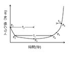
- FIG. 2 is a graph schematically showing a relationship between a torque value obtained by measurement using a lab plast mill and measurement time.
- a measurement start point of Laboplastmill measured as P 1 the torque value is the lowest value to become a point (the minimum torque value) and P 3
- the P 3 from P 1 the point at which the torque value is two times the minimum torque value between leading and P 2
- the torque value after a P 3 A point at which 3 N ⁇ m is obtained is defined as P 5
- a point at which the torque value reaches 6 N ⁇ m after passing through P 3 is defined as P 6 .
- the measurement start point of the lab plast mill measurement is a point where the torque starts to drop after the material is put into the lab plast mill and the torque suddenly rises.
- the sealing resin composition has a time T in which the torque value is not more than twice the minimum torque value when the torque value is measured over time using a lab plast mill at a rotation speed of 30 rpm and a measurement temperature of 175 ° C. 1 is 15 seconds or more and 100 seconds or less.
- T 1 the time in which the torque value is not more than twice the minimum torque value when the torque value is measured over time using a lab plast mill at a rotation speed of 30 rpm and a measurement temperature of 175 ° C. 1 is 15 seconds or more and 100 seconds or less.
- the sealing resin composition has a minimum torque value of 0.5 N ⁇ m or more and 2.5 N when a torque value is measured over time using a lab plast mill at a rotation speed of 30 rpm and a measurement temperature of 175 ° C. -M or less.
- the torque value at P 3 corresponds to the lowest torque value.
- the minimum torque value is more preferably 0.5 N ⁇ m or more and 2.0 N ⁇ m or less from the viewpoint of more effectively improving the balance of filling property and adhesion, and 0.6 N More preferably, it is m or more and 2.0 N ⁇ m or less, and particularly preferably 0.6 N ⁇ m or more and 1.2 N ⁇ m or less.
- the filling time of the sealing resin composition and the adhesion of the sealing resin 14 to the wiring substrate 12 are controlled by simultaneously controlling the time T 1 and the minimum torque value of the sealing resin composition. It is possible to improve the balance between the characteristics. The reason for this is not clear, but the flow characteristics of the sealing resin composition can be controlled so as not to cause a difference in fluidity depending on the location while obtaining sufficient fluidity for molding. It is presumed that the generation of unfilled portions can be suppressed and the decrease in adhesion due to a temperature change when forming the sealing resin 14 can be suppressed.
- the sealing resin composition is a time T from the start of measurement until the minimum torque value is reached when the torque value is measured over time using, for example, a lab plast mill at a rotation speed of 30 rpm and a measurement temperature of 175 ° C. 2 is 5 seconds or more and 40 seconds or less.
- the time from P 1 to P 3 corresponds to T 2 .
- it is more preferable from the viewpoint of improving the filling property time T 2 is 35 seconds or less 10 seconds or more.
- the sealing resin composition has a torque value of 3 N ⁇ after passing through the minimum torque value when the torque value is measured over time under the conditions of a rotation speed of 30 rpm and a measurement temperature of 175 ° C. using a lab plast mill.
- the time T 3 from the point at which m is reached to the point at which the torque value is 6 N ⁇ m is not less than 2 seconds and not more than 20 seconds.
- the time from P 5 to P 6 corresponds to T 3 .
- the time T 3 is more preferably 3 seconds or more from the viewpoint of further reducing the internal stress during molding and further improving the filling property. From the viewpoint of further improving the manufacturing efficiency, it is more preferred time T 3 is less than 10 seconds.
- the present inventor presumed that it is important to mix each component and then finely pulverize the obtained mixture with a rotating ball mill under certain conditions. Yes.
- adjusting the conditions such as the volume filling rate of the balls with respect to the device volume and the material supply amount (kg / hr) and performing fine pulverization with a rotating ball mill may result in the glass transition temperature Tg and time of the sealing resin composition.
- T 1 it is believed that the time T 2, affect the time T 3, and the lowest torque value.
- controlling the conditions of the melt-kneading step after fine pulverization with a rotating ball mill, and continuously performing the process from mixing of each component to melt-kneading affect the properties of the sealing resin composition. It can be given.
- the preparation method of the resin composition for sealing is not limited to the above.
- the molding shrinkage measured according to JIS K 6911 of the sealing resin composition can be 0.4% or less.
- the molding shrinkage rate of the sealing resin composition is more preferably 0.3% or less.
- the lower limit of the molding shrinkage ratio of the sealing resin composition is not particularly limited, and can be, for example, 0%, but is 0.1% from the viewpoint of improving mold release properties. Is more preferable.
- the measurement of the molding shrinkage rate is performed on a test piece manufactured using, for example, a low-pressure transfer molding machine at a mold temperature of 175 ° C., an injection pressure of 6.9 MPa, and a curing time of 120 seconds.
- a low-pressure transfer molding machine at a mold temperature of 175 ° C., an injection pressure of 6.9 MPa, and a curing time of 120 seconds.
- KTS-15 manufactured by Kotaki Seiki Co., Ltd.
- the gel time of the sealing resin composition can be set to 10 seconds to 60 seconds. Thereby, the balance of the filling property and moldability of the resin composition for sealing can be improved.
- the gel time of the sealing resin composition is more preferably from 15 seconds to 50 seconds, and particularly preferably from 18 seconds to 45 seconds.
- the flow length of the sealing resin composition measured by, for example, spiral flow can be 40 cm or more and 150 cm or less.
- the spiral flow flow length of the encapsulating resin composition is more preferably 45 cm or more and 125 cm or less.
- a mold temperature of 175 ° C. was applied to a spiral flow measurement mold according to EMMI-1-66.
- the sealing resin composition is injected under the conditions of an injection pressure of 6.9 MPa and a curing time of 120 seconds, and the flow length is measured.
- the molding shrinkage rate, the gel time, and the spiral flow flow length of the sealing resin composition are controlled by, for example, controlling the preparation method of the sealing resin composition and the components constituting the sealing resin composition. By appropriately selecting the type and the blending ratio, it is possible to set the ratio within a desired range.
- the sealing resin composition according to the present embodiment includes a thermosetting resin and imidazoles.
- the balance of a fillability and the adhesiveness with respect to a wiring board can be improved.
- the inclusion of imidazoles can more effectively improve the balance between the adhesion to the wiring board 12 and the temperature cycle resistance. For this reason, it becomes possible to contribute to the reliability improvement of the vehicle-mounted electronic control unit 10.
- each component which comprises the resin composition for sealing is explained in full detail.
- thermosetting resin (A) is, for example, one or more selected from the group consisting of epoxy resins, phenol resins, oxetane resins, (meth) acrylate resins, unsaturated polyester resins, diallyl phthalate resins, and maleimide resins. including. Among these, it is particularly preferable to include an epoxy resin from the viewpoint of improving curability, storage stability, heat resistance, moisture resistance, and chemical resistance.
- the epoxy resin contained in the thermosetting resin (A) monomers, oligomers and polymers generally having two or more epoxy groups in one molecule can be used, and the molecular weight and molecular structure are not particularly limited.
- the epoxy resin is, for example, a biphenyl type epoxy resin; a bisphenol type epoxy resin such as a bisphenol A type epoxy resin, a bisphenol F type epoxy resin, or a tetramethylbisphenol F type epoxy resin; a stilbene type epoxy resin; a phenol novolac type epoxy.
- novolak type epoxy resin such as cresol novolak type epoxy resin
- polyfunctional epoxy resin such as trisphenol type epoxy resin exemplified by triphenolmethane type epoxy resin, alkyl-modified triphenolmethane type epoxy resin, etc .
- having phenylene skeleton Phenol aralkyl type epoxy resin, naphthol aralkyl type epoxy resin having phenylene skeleton, phenol aralkyl type epoxy resin having biphenylene skeleton, bif Phenol aralkyl type epoxy resins such as naphthol aralkyl type epoxy resins having a nylene skeleton
- naphthol type epoxy resins such as dihydroxynaphthalene type epoxy resins and epoxy resins obtained by glycidyl etherification of dihydroxynaphthalene dimers; triglycidyl isocyanurate; Triazine nucleus-containing epoxy resins such as monoallyl diglycidyl isocyan
- the inclusion of one or more selected from a novolac type epoxy resin, a biphenyl type epoxy resin, and a phenol aralkyl type epoxy resin has various properties such as adhesion, fillability, heat resistance, and moisture resistance. It is more preferable from the viewpoint of improving the balance.
- the content of the thermosetting resin (A) in the encapsulating resin composition is preferably 2% by weight or more, more preferably 3% by weight or more with respect to the entire encapsulating resin composition. It is particularly preferably 4% by weight or more.
- the content of the thermosetting resin (A) in the sealing resin composition is preferably 50% by weight or less, and preferably 30% by weight or less, with respect to the entire sealing resin composition. Is more preferable, and it is especially preferable that it is 15 weight% or less.
- the resin composition for sealing can contain a hardening
- the curing agent (B) contained in the encapsulating resin composition can be roughly classified into three types, for example, a polyaddition type curing agent, a catalyst type curing agent, and a condensation type curing agent.
- Examples of the polyaddition type curing agent used as the curing agent (B) include aliphatic polyamines such as diethylenetriamine (DETA), triethylenetetramine (TETA), and metaxylylenediamine (MXDA), diaminodiphenylmethane (DDM), m -Polyamine compounds including aromatic polyamines such as phenylenediamine (MPDA) and diaminodiphenylsulfone (DDS), dicyandiamide (DICY), organic acid dihydrazide, etc .; hexahydrophthalic anhydride (HHPA), methyltetrahydrophthalic anhydride (MTHPA) ) And other aromatic acid anhydrides such as trimellitic anhydride (TMA), pyromellitic anhydride (PMDA), and benzophenone tetracarboxylic acid (BTDA); Phenolic resin-based curing agents such as diol resins, polyvinylphenols, aral
- Catalytic curing agents used as the curing agent (B) include tertiary amine compounds such as benzyldimethylamine (BDMA) and 2,4,6-trisdimethylaminomethylphenol (DMP-30); One type or two or more types selected from the group consisting of Lewis acids are included.
- BDMA benzyldimethylamine
- DMP-30 2,4,6-trisdimethylaminomethylphenol
- the condensation type curing agent used as the curing agent (B) is, for example, one type selected from the group consisting of a resol type phenol resin; a urea resin such as a methylol group-containing urea resin; and a melamine resin such as a methylol group-containing melamine resin; Including two or more types.
- a phenol resin-based curing agent from the viewpoint of improving the balance of flame resistance, moisture resistance, electrical properties, curability, storage stability, and the like.
- a phenol resin-based curing agent monomers, oligomers, and polymers in general having two or more phenolic hydroxyl groups in one molecule can be used, and the molecular weight and molecular structure are not particularly limited.
- the phenol resin-based curing agent used as the curing agent (B) is, for example, a novolac type phenol resin such as a phenol novolak resin, a cresol novolac resin, or a bisphenol novolac; a polyvinyl phenol; a polyfunctional phenol resin such as a triphenolmethane type phenol resin; Modified phenol resins such as terpene-modified phenol resin and dicyclopentadiene-modified phenol resin; phenol aralkyl resins having a phenylene skeleton and / or biphenylene skeleton, phenol aralkyl type phenol resins such as naphthol aralkyl resin having phenylene and / or biphenylene skeleton; bisphenol One type or two or more types selected from the group consisting of bisphenol compounds such as A and bisphenol F are included. Among these, from the viewpoint of improving the curability of the sealing resin composition, it is more preferable to include at least one of
- the content of the curing agent (B) in the sealing resin composition is preferably 1% by weight or more, more preferably 2% by weight or more, based on the whole sealing resin composition. It is particularly preferable that the amount be at least% by weight.
- content of the curing agent (B) in the resin composition for sealing is 40 weight% or less with respect to the whole resin composition for sealing, and it is more preferable that it is 25 weight% or less. It is preferably 10% by weight or less.
- the sealing resin composition contains a curing catalyst (C).
- a curing catalyst (C) As the curing catalyst (C), a crosslinking reaction between a thermosetting resin (A) (for example, an epoxy group of an epoxy resin) and a curing agent (B) (for example, a phenolic hydroxyl group of a phenol resin-based curing agent) is performed. What can be promoted can be used.
- A thermosetting resin
- B for example, a phenolic hydroxyl group of a phenol resin-based curing agent
- the sealing resin composition according to this embodiment contains imidazoles as the curing catalyst (C).
- imidazoles include imidazole, 2-methylimidazole, 2-undecylimidazole, 2-heptadecylimidazole, 1,2-dimethylimidazole, 2-ethyl-4-methylimidazole, 2-phenylimidazole, and 2-phenyl-4.
- the content of imidazoles is preferably 0.01% by weight or more, more preferably 0.03% by weight or more, and more preferably 0.05% by weight or more with respect to the entire sealing resin composition. Particularly preferred.
- the content of imidazoles is preferably 2.0% by weight or less, more preferably 1.0% by weight or less, and more preferably 0.5% by weight with respect to the entire sealing resin composition. The following is particularly preferable.
- the curing catalyst (C) contains, for example, an organic phosphine, a tetra-substituted phosphonium compound, a phosphobetaine compound, an adduct of a phosphine compound and a quinone compound, an adduct of a phosphonium compound and a silane compound, and the like.
- the compound may further include one or more selected from amine-based curing accelerators other than imidazoles such as 1,8-diazabicyclo (5.4.0) undecene.
- amine-based curing accelerators other than imidazoles
- 1,8-diazabicyclo (5.4.0) undecene 1,8-diazabicyclo
- Examples of the organic phosphine that can be used in the sealing resin composition include a first phosphine such as ethylphosphine and phenylphosphine; a second phosphine such as dimethylphosphine and diphenylphosphine; trimethylphosphine, triethylphosphine, tributylphosphine, and triphenyl. Third phosphine such as phosphine can be mentioned.
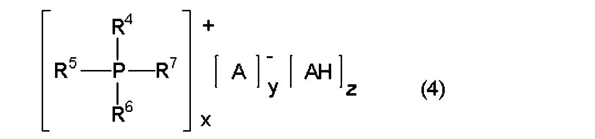
- Examples of the tetra-substituted phosphonium compound that can be used in the sealing resin composition include compounds represented by the following general formula (4).
- P represents a phosphorus atom.
- R 4 , R 5 , R 6 and R 7 represent an aromatic group or an alkyl group.
- A is selected from a hydroxyl group, a carboxyl group, and a thiol group.
- An anion of an aromatic organic acid having at least one functional group in the aromatic ring, AH is an aromatic having at least one functional group selected from a hydroxyl group, a carboxyl group, and a thiol group in the aromatic ring.
- Represents an organic acid, where x and y are numbers from 1 to 3, z is a number from 0 to 3, and x y.
- the compound represented by General formula (4) is obtained as follows, for example, it is not limited to this. First, a tetra-substituted phosphonium halide, an aromatic organic acid and a base are mixed in an organic solvent and mixed uniformly to generate an aromatic organic acid anion in the solution system. Then, when water is added, the compound represented by the general formula (4) can be precipitated.
- R 4 , R 5 , R 6 and R 7 bonded to the phosphorus atom are phenyl groups
- AH is a compound having a hydroxyl group in an aromatic ring, that is, phenols.
- A is preferably an anion of the phenol.
- phenols examples include monocyclic phenols such as phenol, cresol, resorcin, and catechol, condensed polycyclic phenols such as naphthol, dihydroxynaphthalene, and anthraquinol, bisphenols such as bisphenol A, bisphenol F, and bisphenol S, Examples include polycyclic phenols such as phenylphenol and biphenol.
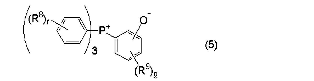
- Examples of the phosphobetaine compound that can be used in the encapsulating resin composition include compounds represented by the following general formula (5).
- R 8 represents an alkyl group having 1 to 3 carbon atoms
- R 9 represents a hydroxyl group
- f is a number from 0 to 5
- g is a number from 0 to 3.
- the compound represented by the general formula (5) is obtained as follows, for example. First, it is obtained through a step of bringing a triaromatic substituted phosphine, which is a third phosphine, into contact with a diazonium salt and replacing the triaromatic substituted phosphine with a diazonium group of the diazonium salt.
- a triaromatic substituted phosphine which is a third phosphine
- the present invention is not limited to this.
- Examples of the adduct of a phosphine compound and a quinone compound that can be used in the sealing resin composition include compounds represented by the following general formula (6).
- P represents a phosphorus atom.
- R 10 , R 11 and R 12 represent an alkyl group having 1 to 12 carbon atoms or an aryl group having 6 to 12 carbon atoms, and are the same as each other.
- R 13 , R 14 and R 15 each represents a hydrogen atom or a hydrocarbon group having 1 to 12 carbon atoms and may be the same or different from each other, and R 14 and R 15 are bonded to each other. And may have a circular structure.
- Examples of the phosphine compound used as an adduct of a phosphine compound and a quinone compound include an aromatic ring such as triphenylphosphine, tris (alkylphenyl) phosphine, tris (alkoxyphenyl) phosphine, trinaphthylphosphine, and tris (benzyl) phosphine.
- aromatic ring such as triphenylphosphine, tris (alkylphenyl) phosphine, tris (alkoxyphenyl) phosphine, trinaphthylphosphine, and tris (benzyl) phosphine.
- Those having a substituent or a substituent such as an alkyl group and an alkoxyl group are preferred, and examples of the substituent such as an alkyl group and an alkoxyl group include those having 1 to 6 carbon atoms. From the viewpoint of availability, triphenyl
- examples of the quinone compound used for the adduct of the phosphine compound and the quinone compound include benzoquinone and anthraquinones, and among them, p-benzoquinone is preferable from the viewpoint of storage stability.
- the adduct can be obtained by contacting and mixing in a solvent capable of dissolving both organic tertiary phosphine and benzoquinone.
- the solvent is preferably a ketone such as acetone or methyl ethyl ketone, which has low solubility in the adduct.
- the present invention is not limited to this.
- R 10 , R 11 and R 12 bonded to the phosphorus atom are phenyl groups, and R 13 , R 14 and R 15 are hydrogen atoms, ie, 1,
- a compound in which 4-benzoquinone and triphenylphosphine are added is preferable in that it reduces the thermal elastic modulus of the cured product of the encapsulating resin composition.
- Examples of the adduct of a phosphonium compound and a silane compound that can be used in the sealing resin composition include a compound represented by the following general formula (7).
- R 16 , R 17 , R 18 and R 19 are each an organic group having an aromatic ring or a heterocyclic ring, or an aliphatic group. Represents a group, which may be the same or different from each other, wherein R 20 is an organic group bonded to the groups Y 2 and Y 3.
- R 21 represents the groups Y 4 and Y 5 ; Y 2 and Y 3 represent a group formed by releasing a proton from a proton donating group, and groups Y 2 and Y 3 in the same molecule are bonded to a silicon atom to form a chelate structure.
- Y 4 and Y 5 represent a group formed by releasing a proton from a proton donating group, and groups Y 4 and Y 5 in the same molecule are combined with a silicon atom to form a chelate structure.
- R 20, and R 21 are mutually Or different mere, Y 2, Y 3, Y 4 and Y 5 may .Z 1 also being the same or different organic group having an aromatic ring or a heterocyclic ring or fat, A group.
- examples of R 16 , R 17 , R 18 and R 19 include a phenyl group, a methylphenyl group, a methoxyphenyl group, a hydroxyphenyl group, a naphthyl group, a hydroxynaphthyl group, a benzyl group, and a methyl group.
- alkyl group such as phenyl group, methylphenyl group, methoxyphenyl group, hydroxyphenyl group, hydroxynaphthyl group, alkoxy group, etc.
- An aromatic group having a substituent such as a hydroxyl group or an unsubstituted aromatic group is more preferable.
- R 20 is an organic group bonded to Y 2 and Y 3.
- R 21 is an organic group that binds to groups Y 4 and Y 5 .
- Y 2 and Y 3 are groups formed by proton-donating groups releasing protons, and groups Y 2 and Y 3 in the same molecule are combined with a silicon atom to form a chelate structure.
- Y 4 and Y 5 are groups formed by proton-donating groups releasing protons, and groups Y 4 and Y 5 in the same molecule are combined with a silicon atom to form a chelate structure.
- the groups R 20 and R 21 may be the same or different from each other, and the groups Y 2 , Y 3 , Y 4 , and Y 5 may be the same or different from each other.
- the proton donor releases two protons.
- the proton donor is preferably an organic acid having at least two carboxyl groups or hydroxyl groups in the molecule, and further, a carboxyl group or hydroxyl group on the adjacent carbon constituting the aromatic ring. Are preferable, and aromatic compounds having at least two hydroxyl groups on adjacent carbons constituting the aromatic ring are more preferable.
- catechol pyrogallol, 1,2-dihydroxynaphthalene, 2,3- Dihydroxynaphthalene, 2,2′-biphenol, 1,1′-bi-2-naphthol, salicylic acid, 1-hydroxy-2-naphthoic acid, 3- Examples include droxy-2-naphthoic acid, chloranilic acid, tannic acid, 2-hydroxybenzyl alcohol, 1,2-cyclohexanediol, 1,2-propanediol, and glycerin. Among these, catechol, 1,2- Dihydroxynaphthalene and 2,3-dihydroxynaphthalene are more preferable.
- Z 1 in the general formula (7) represents an organic group or an aliphatic group having an aromatic ring or a heterocyclic ring, and specific examples thereof include a methyl group, an ethyl group, a propyl group, a butyl group, Aliphatic hydrocarbon groups such as hexyl group and octyl group, aromatic hydrocarbon groups such as phenyl group, benzyl group, naphthyl group and biphenyl group, glycidyloxy groups such as glycidyloxypropyl group, mercaptopropyl group and aminopropyl group Reactive groups such as mercapto groups, alkyl groups having amino groups, and vinyl groups.
- methyl groups, ethyl groups, phenyl groups, naphthyl groups, and biphenyl groups are preferred from the viewpoint of thermal stability. More preferable.
- a silane compound such as phenyltrimethoxysilane and a proton donor such as 2,3-dihydroxynaphthalene are added to a flask containing methanol, and then dissolved.
- Sodium methoxide-methanol solution is added dropwise with stirring.
- crystals are precipitated. The precipitated crystals are filtered, washed with water, and vacuum dried to obtain an adduct of a phosphonium compound and a silane compound.
- the content of the curing catalyst (C) is preferably 0.05% by weight or more, more preferably 0.08% by weight or more, and 0.10% by weight with respect to the entire sealing resin composition.
- the above is particularly preferable.
- content of a curing catalyst (C) is preferably 2.0% by weight or less, more preferably 1.0% by weight or less, based on the whole sealing resin composition. It is particularly preferably 5% by weight or less.
- the resin composition for sealing can contain an inorganic filler (D), for example.
- the inorganic filler (D) contains, for example, one or more selected from the group consisting of silica such as fused silica and crystalline silica, alumina, aluminum hydroxide, magnesium hydroxide, silicon nitride, and aluminum nitride. Can do.
- silica such as fused silica and crystalline silica
- alumina aluminum hydroxide
- magnesium hydroxide silicon nitride
- aluminum nitride aluminum nitride.
- aluminum hydroxide is included from a viewpoint of improving the flame retardance of the sealing resin formed using the resin composition for sealing.
- the case where both a silica and aluminum hydroxide are included can be mentioned as an example of a preferable aspect.
- the inorganic filler (D) can contain, for example, crushed silica. Thereby, the manufacturing cost of the vehicle-mounted electronic control unit 10 can be reduced.
- the content of crushed silica can be, for example, 10 wt% or more and 100 wt% or less with respect to the entire inorganic filler (D), and 15 wt% or more and 95 wt%. It is more preferable to set the weight% or less.
- an inorganic filler (D) can contain spherical silica from a viewpoint which improves the fluidity
- the content of the spherical silica can be, for example, 10% by weight or more and 100% by weight or less, and 15% by weight or more and 95% by weight with respect to the whole inorganic filler (D). It is more preferable to set the weight% or less.
- the case where both spherical silica and crushed silica are included as the inorganic filler (D) can be mentioned as an example of a preferred embodiment.
- an inorganic filler (D) comprises silica
- inorganic filler (D) for example preferably comprises a silica average particle diameter D 50 is 3 ⁇ m or more 50 ⁇ m or less, an average particle diameter D 50 of 10 ⁇ m or more 30 ⁇ m or less More preferably, it contains silica. Thereby, balance, such as a filling property, adhesiveness, moisture resistance, and heat resistance, can be improved more effectively.
- the average particle diameter D 50 of silica can be measured using, for example, a commercially available laser particle size distribution analyzer (for example, SALD-7000 manufactured by Shimadzu Corporation).
- the content of the inorganic filler (D) in the sealing resin composition is preferably 60% by weight or more and more preferably 70% by weight or more with respect to the entire sealing resin composition.
- the content of the inorganic filler (D) in the encapsulating resin composition is preferably 90% by weight or less and more preferably 85% by weight or less with respect to the entire encapsulating resin composition. More preferred.
- the resin composition for sealing can contain a silane coupling agent (E), for example.
- a silane coupling agent (E) can include one or more selected from, for example, epoxy silane, mercaptosilane, aminosilane, alkylsilane, ureidosilane, vinylsilane, and methacrylsilane.
- Examples include vinyltrichlorosilane, vinyltrimethoxysilane, vinyltriethoxysilane, vinyltris ( ⁇ -methoxyethoxy) silane, ⁇ -methacryloxypropyltrimethoxysilane, ⁇ - (3,4-epoxycyclohexyl) ethyltrimethoxy.
- Silane ⁇ -glycidoxypropyltrimethoxysilane, ⁇ -glycidoxypropyltriethoxysilane, ⁇ -glycidoxypropylmethyldimethoxysilane, ⁇ -methacryloxypropylmethyldiethoxysilane, ⁇ -methacryloxypropyltriethoxysilane , Vinyltriacetoxysilane, ⁇ -mercaptopropyltrimethoxysilane, ⁇ -aminopropyltriethoxysilane, ⁇ -anilinopropyltrimethoxysilane, ⁇ -anilinopropylmethyldimethoxysilane ⁇ - [bis ( ⁇ -hydroxyethyl)] aminopropyltriethoxysilane, N- ⁇ - (aminoethyl) - ⁇ -aminopropyltrimethoxysilane, N- ⁇ - (aminoethyl) - ⁇ -aminopropyl
- the content of the silane coupling agent (E) in the sealing resin composition is preferably 0.05% by weight or more, for example, 0.1% by weight or more with respect to the whole sealing resin composition. More preferably, it is particularly preferably 0.15% by weight or more.
- content of a silane coupling agent (E) is more than the said lower limit, the dispersibility of the inorganic filler (D) in the resin composition for sealing can be made more favorable. For this reason, it becomes possible to improve moisture resistance reliability, reflow resistance, etc. more effectively.
- the content of the silane coupling agent (E) in the sealing resin composition is, for example, preferably 2% by weight or less, more preferably 1% by weight or less, and 0.5% by weight. The following is particularly preferable.
- content of a silane coupling agent (E) below the said upper limit, the fluidity
- a coupling agent other than a silane coupling agent for example, a release agent, a colorant, an ion scavenger, an oil, a low stress agent, a flame retardant, and an antioxidant, if necessary.
- a coupling agent can include known coupling agents such as titanium compounds, aluminum chelates, and aluminum / zirconium compounds.
- the releasability-imparting agent is, for example, one or two selected from natural waxes such as carnauba wax, synthetic waxes such as montanic acid ester wax and oxidized polyethylene wax, higher fatty acids such as zinc stearate and metal salts thereof, and paraffin. More than types can be included.
- the colorant can include, for example, one or both of carbon black and black titanium oxide.
- the ion scavenger can include, for example, hydrotalcite.
- the oil can include, for example, silicone oil.
- the low stress agent can include, for example, silicone rubber.
- the flame retardant may include one or more selected from, for example, magnesium hydroxide, zinc borate, zinc molybdate, and phosphazene.
- Antioxidant can contain the 1 type (s) or 2 or more types selected from a phenolic antioxidant, phosphorus antioxidant, and thioether type
- group antioxidant More than types can be included.
- the colorant can include, for
- the manufacturing method of the vehicle-mounted electronic control unit 10 is performed as follows, for example. First, a plurality of electronic components 16 are mounted on at least one surface of the wiring board 12. Next, the plurality of electronic components 16 are encapsulated using an encapsulating resin composition. As the resin composition for sealing, those exemplified above can be used. Hereinafter, the manufacturing method of the vehicle-mounted electronic control unit 10 will be described in detail.
- a plurality of electronic components 16 are mounted on at least one surface of the wiring board 12.
- a plurality of electronic components 16 can be mounted on one surface of the wiring board 12 and another surface opposite to the one surface.
- the vehicle-mounted electronic control unit 10 in which the electronic components 16 are mounted on both surfaces of the wiring board 12 as shown in FIG. 1 can be formed.
- the electronic component 16 may be mounted on only one surface of the wiring board 12 and the electronic component 16 may not be mounted on the other surface.
- the wiring board 12 and the electronic component 16 what was illustrated above is applicable.
- the plurality of electronic components 16 are encapsulated using an encapsulating resin composition.
- the sealing resin 14 for sealing the electronic component 16 is formed.
- the sealing resin composition is molded so as to seal the wiring substrate 12 together with the electronic component 16.
- the in-vehicle electronic control unit 10 illustrated in FIG. 1 is obtained, for example, by sealing and molding one side and the other side of the wiring board 12 and the electronic component 16 mounted on the wiring board 12 with a sealing resin composition. be able to.
- a part or all of the wiring board 12 is sealed together with the plurality of electronic components 16 using the sealing resin composition.
- the manufacturing method of the vehicle-mounted electronic control unit 10 according to the present embodiment can be performed in this manner, for example.
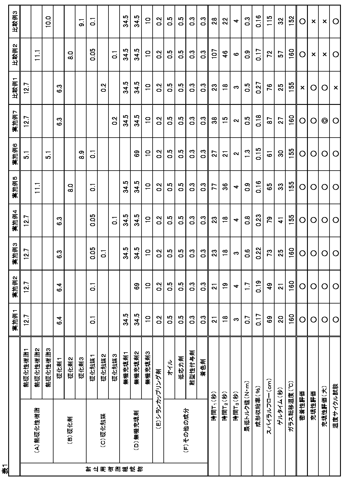
- sealing resin compositions were prepared as follows. First, according to the formulation shown in Table 1, each component was premixed for 20 minutes with a Henschel mixer (capacity 200 liters, rotation speed 900 rpm) set to room temperature. Next, the obtained mixture was used using a continuous rotating ball mill (Nippon Coke Industries, Ltd., dynamic mill MYD25, screw rotation speed 500 rpm, alumina ball diameter 10 mm, volume filling rate of balls with respect to the device volume 50%), The material was supplied at a feed rate of 200 kg / hr and was finely pulverized while maintaining the material temperature at 30 ° C.
- the kneaded mixture was cooled and pulverized to obtain a sealing resin composition.
- each process from the preliminary mixing by a Henschel mixer to obtaining the sealing resin composition was continuously performed.
- Thermosetting resin 1 Orthocresol novolac type epoxy resin (EPICLON N-660, manufactured by DIC Corporation)
- Thermosetting resin 2 phenol aralkyl type epoxy resin having biphenylene skeleton (NC-3000, manufactured by Nippon Kayaku Co., Ltd.)
- Thermosetting resin 3 biphenyl type epoxy resin (YX-4000H, manufactured by Mitsubishi Chemical Corporation)
- Curing agent 1 Novolac type phenolic resin (PR-HF-3, manufactured by Sumitomo Bakelite Co., Ltd.)
- Curing agent 2 phenol aralkyl resin having a phenylene skeleton (XL-225-3L, manufactured by Mitsui Chemicals, Inc.)
- Curing agent 3 Aralkyl type phenolic resin having a biphenylene skeleton (MEH-7851SS, manufactured by Meiwa Kasei Co., Ltd.)
- Curing catalyst 1 2-methylimidazole (2MZ-H, manufactured by Shikoku Kasei Co., Ltd.)
- Curing catalyst 2 Triphenylphosphine (PP360, manufactured by Kay Kasei Co., Ltd.)
- Curing catalyst 3 2-phenylimidazole (2PZ-PW, manufactured by Shikoku Kasei Co., Ltd., fine powder)
- Inorganic filler 3 Aluminum hydroxide
- the time obtained encapsulating resin composition T 1, T 2, T 3 , and the measurement of the minimum torque value was carried out as follows. First, the melting torque of the sealing resin composition was measured over time using a Labo Plast Mill tester (manufactured by Toyo Seiki Seisakusho Co., Ltd., 4C150) under the conditions of a rotation speed of 30 rpm and a measurement temperature of 175 ° C.
- the measurement starting point was the point at which the torque began to drop after the material was put into the lab plast mill tester and the torque suddenly rose. Further, the minimum torque value was calculated from the measurement result.
- the results are shown in Table 1.
- the units of time T 1 , T 2 , and T 3 in Table 1 are seconds, and the unit of the minimum torque value is N ⁇ m.
- cured material of the obtained sealing resin composition was measured as follows. First, a sealing resin composition was injection molded using a low pressure transfer molding machine (“KTS-15” manufactured by Kotaki Seiki Co., Ltd.) at a mold temperature of 175 ° C., an injection pressure of 6.9 MPa, and a curing time of 120 seconds. A test piece of 10 mm ⁇ 4 mm ⁇ 4 mm was obtained. Subsequently, the obtained test piece was post-cured at 175 ° C.
- KTS-15 low pressure transfer molding machine
- thermomechanical analyzer manufactured by Seiko Denshi Kogyo Co., Ltd., TMA100
- TMA100 glass transition temperature
- the sealing resin part of the molded product had a length of 90 mm, a width of 90 mm, and a thickness of 13 mm. Up to 85 mm of the substrate was enclosed in the sealing resin, and 15 mm of the substrate was exposed from one side. Further, the resin thickness on the upper surface side of the substrate was 3.4 mm, and the resin thickness on the lower surface side of the substrate was 8 mm. Subsequently, immediately after taking out the molding from the mold, it was cooled by being immersed in 1 L of 25 ° C. water for 20 minutes. Then, the cooled molded article was subjected to ultrasonic flaw detection using FineSAT manufactured by Hitachi Power Solutions, Ltd., and the presence or absence of peeling between the substrate and the sealing resin was confirmed. Here, the adhesion was evaluated as x when there was peeling, and ⁇ when there was no peeling. The results are shown in Table 1.
- the filling property evaluation by a molded object larger than the said filling property evaluation was performed as follows. First, a solder resist (manufactured by Tamura Corporation, DSR-2200S66-11) was printed and cured on a glass epoxy copper clad laminate (Panasonic Corporation, R-1705, substrate thickness 1.6 mm). A substrate (length: 130 mm, width: 80 mm) was molded by TOWA Corporation YPS-120ton manual press using the sealing resin composition obtained above, with a mold temperature of 175 ° C., an injection time of 20 seconds, and an injection pressure of 8.
- Seal molding was performed under conditions of 4 MPa and a curing time of 120 seconds to obtain a molded product.
- the sealing resin portion of the molded product was 120 mm long, 90 mm wide, and 9.6 mm thick. Up to 115 mm long of the substrate was enclosed in the sealing resin, and 15 mm long of the substrate was exposed from one side. The resin thickness on the upper surface side and the lower surface side of the substrate was 4 mm.
- the appearance of the obtained molded body was visually observed to confirm whether or not it was unfilled by welds.
- the fillability was evaluated as x when the unfilled portion was 1 mm or more, ⁇ when the unfilled portion was less than 1 mm, and ⁇ when there was no unfilled portion. The results are shown in Table 1.
- a seal used for forming the sealing resin of an on-vehicle electronic control unit comprising: a wiring board; a plurality of electronic components mounted on the wiring board; and a sealing resin that seals the electronic components.
- the time T 1 when the torque value is not more than twice the minimum torque value is 15 seconds or more and 100 seconds or less.
- a sealing resin composition In the sealing resin composition according to any one of (1) to (3) above, A sealing resin composition further comprising an inorganic filler. (5) In the sealing resin composition according to (4) above, The inorganic filler is a sealing resin composition containing spherical silica and crushed silica. (6) In the sealing resin composition according to any one of (1) to (5) above, When the torque value is measured over time using a Laboplast mill at a rotation speed of 30 rpm and a measurement temperature of 175 ° C., the torque value becomes 6 N ⁇ m after passing through the minimum torque value.
- the said wiring board is a manufacturing method of the vehicle-mounted electronic control unit which has the soldering resist layer formed with the resin composition containing a silicone compound in the said surface.
- the said wiring board is a vehicle-mounted electronic control unit which has the soldering resist layer formed in the said one surface with the resin composition containing a silicone compound.
- the plurality of electronic components are in-vehicle electronic control units mounted on each of the one surface of the wiring board and the other surface opposite to the one surface.
Landscapes
- Chemical & Material Sciences (AREA)
- Engineering & Computer Science (AREA)
- Medicinal Chemistry (AREA)
- Health & Medical Sciences (AREA)
- Polymers & Plastics (AREA)
- Organic Chemistry (AREA)
- Chemical Kinetics & Catalysis (AREA)
- Manufacturing & Machinery (AREA)
- Microelectronics & Electronic Packaging (AREA)
- Mechanical Engineering (AREA)
- Structures Or Materials For Encapsulating Or Coating Semiconductor Devices Or Solid State Devices (AREA)
- Epoxy Resins (AREA)
- Compositions Of Macromolecular Compounds (AREA)
- Non-Metallic Protective Coatings For Printed Circuits (AREA)
Abstract
Description
配線基板と、前記配線基板上に搭載された複数の電子部品と、前記電子部品を封止する封止樹脂と、を備える車載用電子制御ユニットの前記封止樹脂を形成するために用いられる封止用樹脂組成物であって、
熱硬化性樹脂と、
イミダゾール類と、
を含み、
ラボプラストミルを用いて回転数30rpm、測定温度175℃の条件でトルク値を経時的に測定した際に、トルク値が最低トルク値の2倍以下である時間T1が15秒以上100秒以下であり、最低トルク値が0.5N・m以上2.5N・m以下である封止用樹脂組成物が提供される。
配線基板の少なくとも一面上に複数の電子部品を搭載する工程と、
前記複数の電子部品を、上述の封止用樹脂組成物を用いて封止成形する工程と、
を備える車載用電子制御ユニットの製造方法が提供される。
配線基板と、
前記配線基板の少なくとも一面に搭載された複数の電子部品と、
上述の封止用樹脂組成物を硬化することにより形成され、かつ前記電子部品を封止する封止樹脂と、
を備える車載用電子制御ユニットが提供される。
本実施形態に係る封止用樹脂組成物は、配線基板12と、配線基板12上に搭載された複数の電子部品16と、電子部品16を封止する封止樹脂14と、を備える車載用電子制御ユニット10の封止樹脂14を形成するために用いられるものである。
封止用樹脂組成物は、熱硬化性樹脂と、イミダゾール類と、を含む。また、封止用樹脂組成物は、ラボプラストミルを用いて回転数30rpm、測定温度175℃の条件でトルク値を経時的に測定した際に、トルク値が最低トルク値の2倍以下である時間T1が15秒以上100秒以下であり、最低トルク値が0.5N・m以上2.5N・m以下である。
車載用電子制御ユニット10は、エンジンや各種車載機器等を制御するために用いられる。図1に示すように、車載用電子制御ユニット10は、たとえば配線基板12と、配線基板12の少なくとも一面に搭載された複数の電子部品16と、電子部品16を封止する封止樹脂14と、を備えている。配線基板12は、少なくとも一辺において、外部と接続するための接続端子18を有している。本実施形態の一例に係る車載用電子制御ユニット10は、接続端子18と相手方コネクタを嵌合することによって、接続端子18を介して上記相手方コネクタに電気的に接続されることとなる。
配線基板12の一面に、または一面および他面の双方に設けられた上記ソルダーレジスト層は、たとえばシリコーン化合物を含む樹脂組成物により形成される。これにより、表面平滑性に優れたソルダーレジスト層を実現することができる。
封止用樹脂組成物は、175℃、4時間で加熱して得られる硬化物のガラス転移温度Tgが130℃以上であることが好ましく、140℃以上であることがより好ましく、150℃以上であることがさらに好ましい。これにより、封止用樹脂組成物の充填性と、配線基板12に対する封止樹脂14の密着性と、のバランスのより一層の向上に寄与することができる。また、車載用電子制御ユニット10の耐温度サイクル性を向上させることもできる。本実施形態においては、上記ガラス転移温度Tgが153℃以上であることが、充填性や密着性、耐温度サイクル性のバランスを向上させる観点から、とくに好ましい。
封止用樹脂組成物は、175℃、4時間で加熱して得られる硬化物のガラス転移温度Tgの上限がとくに限定されないが、たとえば、300℃以下、好ましくは250℃以下、より好ましくは200℃以下である。
以下、封止用樹脂組成物を構成する各成分について詳述する。
熱硬化性樹脂(A)は、たとえばエポキシ樹脂、フェノール樹脂、オキセタン樹脂、(メタ)アクリレート樹脂、不飽和ポリエステル樹脂、ジアリルフタレート樹脂、およびマレイミド樹脂からなる群から選択される一種類または二種類以上を含む。これらの中でも、硬化性、保存性、耐熱性、耐湿性、および耐薬品性を向上させる観点から、エポキシ樹脂を含むことがとくに好ましい。
封止用樹脂組成物は、たとえば硬化剤(B)を含むことができる。封止用樹脂組成物に含まれる硬化剤(B)としては、たとえば重付加型の硬化剤、触媒型の硬化剤、および縮合型の硬化剤の3タイプに大別することができる。
封止用樹脂組成物は、硬化触媒(C)を含んでいる。硬化触媒(C)としては、熱硬化性樹脂(A)(たとえば、エポキシ樹脂のエポキシ基)と、硬化剤(B)(たとえば、フェノール樹脂系硬化剤のフェノール性水酸基)と、の架橋反応を促進させるものを用いることができる。


封止用樹脂組成物は、たとえば無機充填剤(D)を含むことができる。無機充填剤(D)は、たとえば溶融シリカ、結晶シリカ等のシリカ、アルミナ、水酸化アルミニウム、水酸化マグネシウム、窒化珪素、および窒化アルミからなる群から選択される一種類または二種類以上を含むことができる。これらの中でも、汎用性に優れている観点から、シリカを含むことがより好ましく、溶融シリカを含むことがとくに好ましい。また、封止用樹脂組成物を用いて形成される封止樹脂の難燃性を向上させる観点からは、水酸化アルミニウムを含むことがより好ましい。本実施形態においては、シリカと水酸化アルミニウムをともに含む場合を、好ましい態様の一例として挙げることができる。
封止用樹脂組成物は、たとえばシランカップリング剤(E)を含むことができる。これにより、無機充填剤(D)の分散性を向上させ、耐湿信頼性や耐リフロー性の向上に寄与することができる。また、封止樹脂14の配線基板12に対する密着性を向上させることも可能となる。シランカップリング剤(E)は、たとえばエポキシシラン、メルカプトシラン、アミノシラン、アルキルシラン、ウレイドシラン、ビニルシラン、およびメタクリルシランから選択される一種または二種以上を含むことができる。
封止用樹脂組成物には、必要に応じて、たとえばシランカップリング剤以外のカップリング剤、離型性付与剤、着色剤、イオン捕捉剤、オイル、低応力剤、難燃剤および酸化防止剤等の各種添加剤のうち1種以上を適宜配合することができる。カップリング剤は、たとえばチタン系化合物、アルミニウムキレート類、アルミニウム/ジルコニウム系化合物等の公知のカップリング剤を含むことができる。離型性付与剤は、たとえばカルナバワックス等の天然ワックス、モンタン酸エステルワックスや酸化ポリエチレンワックス等の合成ワックス、ステアリン酸亜鉛等の高級脂肪酸およびその金属塩類、ならびにパラフィンから選択される一種類または二種類以上を含むことができる。着色剤は、たとえばカーボンブラックおよび黒色酸化チタンのうちのいずれか一方または双方を含むことができる。イオン捕捉剤は、たとえばハイドロタルサイトを含むことができる。オイルは、たとえばシリコーンオイルを含むことができる。低応力剤は、たとえばシリコーンゴムを含むことができる。難燃剤は、たとえば水酸化マグネシウム、ホウ酸亜鉛、モリブデン酸亜鉛、およびホスファゼンから選択される一種類または二種類以上を含むことができる。酸化防止剤は、フェノール系酸化防止剤、リン系酸化防止剤およびチオエーテル系酸化防止剤から選択される一種類または二種類以上を含むことができる。
本実施形態に係る車載用電子制御ユニット10の製造方法は、たとえば以下のように行われる。まず、配線基板12の少なくとも一面上に複数の電子部品16を搭載する。次いで、複数の電子部品16を、封止用樹脂組成物を用いて封止成形する。封止用樹脂組成物としては、上記に例示したものを用いることができる。
以下、車載用電子制御ユニット10の製造方法について詳述する。
本実施形態に係る車載用電子制御ユニット10の製造方法は、たとえばこのようにして行うことができる。
実施例1~7および比較例1および3のそれぞれについて、以下のように封止用樹脂組成物を調製した。まず、表1に示す配合に従って、各成分を、室温状態に設定したヘンシェルミキサー(容量200リットル、回転数900rpm)で20分間予備混合した。次いで、得られた混合物を、連続式回転ボールミル(日本コークス工業(株)製ダイナミックミルMYD25、スクリュー回転数500rpm、アルミナ製ボール径10mm、装置容積に対するボールの体積充填率50%)を用いて、材料供給量200kg/hrで材料温度を30℃以下に保ちながら微粉砕した。次いで、微粉砕された混合物を、単軸押出混練機(スクリュー径D=46mm、押出機長さ=500mm、溶融混練部長さ=7D、スクリュー回転数200rpm、吐出量30kg/hr)を用いて溶融混練した。次いで、混練後の混合物を冷却し、粉砕して封止用樹脂組成物を得た。なお、ヘンシェルミキサーによる予備混合から、封止用樹脂組成物を得るまでの各工程は、連続的に行った。
熱硬化性樹脂1:オルソクレゾールノボラック型エポキシ樹脂(EPICLON N-660、DIC(株)製)
熱硬化性樹脂2:ビフェニレン骨格を有するフェノールアラルキル型エポキシ樹脂(NC-3000、日本化薬(株)製)
熱硬化性樹脂3:ビフェニル型エポキシ樹脂(YX-4000H、三菱化学(株)製)
硬化剤1:ノボラック型フェノール樹脂(PR-HF-3、住友ベークライト(株)製)
硬化剤2:フェニレン骨格を有するフェノールアラルキル樹脂(XL-225-3L、三井化学(株)製)
硬化剤3:ビフェニレン骨格を有するアラルキル型フェノール樹脂(MEH-7851SS、明和化成(株)製)
硬化触媒1:2-メチルイミダゾール(2MZ-H、四国化成(株)製)
硬化触媒2:トリフェニルホスフィン(PP360、ケイ・アイ化成(株)製)
硬化触媒3:2-フェニルイミダゾール(2PZ-PW、四国化成(株)製、微粉末)
無機充填剤1:球状シリカ(FB-950、電気化学工業(株)製、平均粒径D50=24μm)
無機充填剤2:破砕シリカ(RD-8、(株)龍森製、平均粒径D50=15μm)
無機充填剤3:水酸化アルミニウム
γ-アミノプロピルトリエトキシシラン(KBE-903、信越化学工業(株)製)
オイル:シリコーンオイル(FZ-3730、東レ・ダウコーニング(株)製)
低応力剤:シリコーンゴム(CF2152、東レ・ダウコーニング(株)製)
離型性付与剤:モンタン酸エステルワックス(リコルブWE-4、クラリアントジャパン(株)製)
着色剤:カーボンブラック(#5、三菱化学(株)製)
各実施例および各比較例について、得られた封止用樹脂組成物について時間T1、T2、T3、および最低トルク値の測定を次のように行った。まず、ラボプラストミル試験機((株)東洋精機製作所製、4C150)を用いて、回転数30rpm、測定温度175℃の条件で封止用樹脂組成物の溶融トルクを経時的に測定した。次いで、トルク値が最低トルク値の2倍以下である時間T1と、測定開始から最低トルク値に到達するまでの時間T2と、最低トルク値を経た後にトルク値が3N・mとなる点からトルク値が6N・mとなる点までの時間T3と、を測定結果に基づいて算出した。測定開始点は、ラボプラストミル試験機に材料を投入し、急激にトルクが立ち上がった後、トルクが下がり始める点とした。また、測定結果から、最低トルク値を算出した。結果を表1に示す。表1における時間T1、T2、およびT3の単位は秒であり、最低トルク値の単位はN・mである。
各実施例および各比較例について、得られた封止用樹脂組成物の成形収縮率を測定した。測定は、低圧トランスファー成形機(コータキ精機(株)製「KTS-15」)を用いて金型温度175℃、注入圧力6.9MPa、硬化時間120秒の条件で作製した試験片に対して、JIS K 6911に準じて行った。結果を表1に示す。表1における単位は%である。
各実施例および各比較例について、得られた封止用樹脂組成物に対しスパイラルフロー測定を行った。スパイラルフロー測定は、低圧トランスファー成形機(コータキ精機(株)製「KTS-15」)を用いて、EMMI-1-66に準じたスパイラルフロー測定用の金型に金型温度175℃、注入圧力6.9MPa、硬化時間120秒の条件で封止用樹脂組成物を注入し、流動長を測定することにより行った。結果を表1に示す。表1における単位はcmである。
各実施例および各比較例について、得られた封止用樹脂組成物のゲルタイムを測定した。ゲルタイムの測定は、175℃に加熱した熱板上で封止用樹脂組成物を溶融した後、へらで練りながら硬化するまでの時間(ゲルタイム)を測定することにより行った。結果を表1に示す。表1における単位は秒である。
各実施例および各比較例について、得られた封止用樹脂組成物の硬化物のガラス転移温度(Tg)を以下のように測定した。まず、低圧トランスファー成形機(コータキ精機(株)製「KTS-15」)を用いて金型温度175℃、注入圧力6.9MPa、硬化時間120秒で封止用樹脂組成物を注入成形し、10mm×4mm×4mmの試験片を得た。次いで、得られた試験片を175℃、4時間で後硬化した後、熱機械分析装置(セイコー電子工業(株)製、TMA100)を用いて、測定温度範囲0℃~320℃、昇温速度5℃/分の条件下で測定を行った。そして、この測定結果から、ガラス転移温度(Tg)を算出した。結果を表1に示す。表1における単位は℃である。
各実施例および各比較例について、基板に対する封止樹脂の密着性を以下のように評価した。まず、ガラスエポキシ銅張積層板(パナソニック(株)製、R-1705、基板厚み1.6mm)にソルダーレジスト((株)タムラ製作所製、DSR-2200S66-11)を印刷、硬化して得た基板(縦100mm、幅80mm)を、上記で得られた封止用樹脂組成物を用いてTOWA(株)製YPS-120tonマニュアルプレスにより金型温度175℃、注入時間20秒、注入圧力8.4MPa、硬化時間120秒の条件にて封止成形し、成形物を得た。成形物の封止樹脂部は縦90mm、幅90mm、厚さ13mmであり、基板の縦85mmまでが封止樹脂中に封入され、一辺から基板の縦15mmが露出していた。また、基板上面側の樹脂厚みは3.4mmであり、基板下面側の樹脂厚みは8mmであった。次いで、成形物を金型から取り出した直後に1Lの25℃の水の中に20分間沈めて冷却した。次いで、冷却した成形物を(株)日立パワーソリューションズ製FineSATにて超音波探傷して、基板と封止樹脂との剥離の有無を確認した。ここでは、剥離があれば×、剥離が無ければ○として、密着性を評価した。結果を表1に示す。
各実施例および各比較例について、上記密着性評価において超音波探傷を行った成形体の外観を目視で観察し、ウェルドによる未充填の有無を確認した。そして、未充填部分があれば×、未充填部分がなければ○として、充填性を評価した。結果を表1に示す。
各実施例および各比較例について、上記充填性評価より大きな成形体での充填性評価を以下の通り行った。まず、ガラスエポキシ銅張積層板(パナソニック(株)製、R-1705、基板厚み1.6mm)にソルダーレジスト((株)タムラ製作所製、DSR-2200S66-11)を印刷、硬化して得た基板(縦130mm、幅80mm)を、上記で得られた封止用樹脂組成物を用いてTOWA(株)製YPS-120tonマニュアルプレスにより金型温度175℃、注入時間20秒、注入圧力8.4MPa、硬化時間120秒の条件にて封止成形し、成形物を得た。成形物の封止樹脂部は縦120mm、幅90mm、厚さ9.6mmであり、基板の縦115mmまでが封止樹脂中に封入され、一辺から基板の縦15mmが露出していた。また、基板上面側・下面側の樹脂厚みはともに4mmであった。得られた成形体の外観を目視で観察し、ウェルドによる未充填の有無を確認した。そして、未充填部分が1mm以上であれば×、未充填部分が1mm未満であれば○、未充填部分がなければ◎として、充填性を評価した。結果を表1に示す。
各実施例および各比較例について、上記密着性評価において超音波探傷を行った成形体を、温度サイクル試験(-40℃30分、125℃30分、1サイクル1時間)に1000サイクル投入した後、(株)日立パワーソリューションズ製FineSATにて再度超音波探傷した。そして、新しい剥離の発生、または剥離の進展の有無を確認した。ここでは、新たな剥離の発生または剥離の進展があれば×、新たな剥離の発生および剥離の進展がなければ○として、温度サイクル試験による評価を行った。結果を表1に示す。
本発明は以下の態様も取り得る。
(1)
配線基板と、前記配線基板上に搭載された複数の電子部品と、前記電子部品を封止する封止樹脂と、を備える車載用電子制御ユニットの前記封止樹脂を形成するために用いられる封止用樹脂組成物であって、
熱硬化性樹脂と、
イミダゾール類と、
を含み、
175℃、4時間で加熱して得られる硬化物のガラス転移温度が150℃以上であり、
ラボプラストミルを用いて回転数30rpm、測定温度175℃の条件でトルク値を経時的に測定した際に、トルク値が最低トルク値の2倍以下である時間T1が15秒以上100秒以下であり、最低トルク値が0.5N・m以上2.5N・m以下である封止用樹脂組成物。
(2)
上記(1)に記載の封止用樹脂組成物において、
JIS K 6911に準じて測定される成形収縮率が、0.4%以下である封止用樹脂組成物。
(3)
上記(1)または(2)に記載の封止用樹脂組成物において、
ラボプラストミルを用いて回転数30rpm、測定温度175℃の条件でトルク値を経時的に測定した際に、測定開始から最低トルク値に到達するまでの時間T2が、5秒以上40秒以下である封止用樹脂組成物。
(4)
上記(1)~(3)いずれか一つに記載の封止用樹脂組成物において、
無機充填剤をさらに含む封止用樹脂組成物。
(5)
上記(4)に記載の封止用樹脂組成物において、
前記無機充填剤は、球状シリカおよび破砕シリカを含む封止用樹脂組成物。
(6)
上記(1)~(5)いずれか一つに記載の封止用樹脂組成物において、
ラボプラストミルを用いて回転数30rpm、測定温度175℃の条件でトルク値を経時的に測定した際に、最低トルク値を経た後にトルク値が3N・mとなる点から、トルク値が6N・mとなる点までの時間T3が2秒以上20秒以下である封止用樹脂組成物。
(7)
配線基板の少なくとも一面上に複数の電子部品を搭載する工程と、
前記複数の電子部品を、上記(1)~(6)いずれか一つに記載の封止用樹脂組成物を用いて封止成形する工程と、
を備える車載用電子制御ユニットの製造方法。
(8)
上記(7)に記載の車載用電子制御ユニットの製造方法において、
前記配線基板は、前記一面において、シリコーン化合物を含む樹脂組成物により形成されたソルダーレジスト層を有する車載用電子制御ユニットの製造方法。
(9)
上記(7)または(8)に記載の車載用電子制御ユニットの製造方法において、
前記複数の電子部品を搭載する前記工程において、前記複数の電子部品は、前記配線基板の前記一面と、前記一面とは反対の他面と、のそれぞれに搭載される車載用電子制御ユニットの製造方法。
(10)
上記(7)~(9)いずれか一つに記載の車載用電子制御ユニットの製造方法において、
前記複数の電子部品を封止成形する前記工程において、前記複数の電子部品とともに前記配線基板の一部または全部が前記封止用樹脂組成物を用いて封止される車載用電子制御ユニットの製造方法。
(11)
配線基板と、
前記配線基板の少なくとも一面に搭載された複数の電子部品と、
上記(1)~(6)いずれか一つに記載の封止用樹脂組成物を硬化することにより形成され、かつ前記電子部品を封止する封止樹脂と、
を備える車載用電子制御ユニット。
(12)
上記(11)に記載の車載用電子制御ユニットにおいて、
前記配線基板は、前記一面において、シリコーン化合物を含む樹脂組成物により形成されたソルダーレジスト層を有する車載用電子制御ユニット。
(13)
上記(11)または(12)に記載の車載用電子制御ユニットにおいて、
前記複数の電子部品は、前記配線基板の前記一面と、前記一面とは反対の他面と、のそれぞれに搭載されている車載用電子制御ユニット。
Claims (14)
- 配線基板と、前記配線基板上に搭載された複数の電子部品と、前記電子部品を封止する封止樹脂と、を備える車載用電子制御ユニットの前記封止樹脂を形成するために用いられる封止用樹脂組成物であって、
熱硬化性樹脂と、
イミダゾール類と、
を含み、
ラボプラストミルを用いて回転数30rpm、測定温度175℃の条件でトルク値を経時的に測定した際に、トルク値が最低トルク値の2倍以下である時間T1が15秒以上100秒以下であり、最低トルク値が0.5N・m以上2.5N・m以下である封止用樹脂組成物。 - 請求項1に記載の封止用樹脂組成物において、
前記封止用樹脂組成物を175℃、4時間で加熱して得られる硬化物のガラス転移温度が130℃以上である封止用樹脂組成物。 - 請求項1または2に記載の封止用樹脂組成物において、
JIS K 6911に準じて測定される成形収縮率が、0.4%以下である封止用樹脂組成物。 - 請求項1~3いずれか一項に記載の封止用樹脂組成物において、
ラボプラストミルを用いて回転数30rpm、測定温度175℃の条件でトルク値を経時的に測定した際に、測定開始から最低トルク値に到達するまでの時間T2が、5秒以上40秒以下である封止用樹脂組成物。 - 請求項1~4いずれか一項に記載の封止用樹脂組成物において、
無機充填剤をさらに含む封止用樹脂組成物。 - 請求項5に記載の封止用樹脂組成物において、
前記無機充填剤は、球状シリカおよび破砕シリカを含む封止用樹脂組成物。 - 請求項1~6いずれか一項に記載の封止用樹脂組成物において、
ラボプラストミルを用いて回転数30rpm、測定温度175℃の条件でトルク値を経時的に測定した際に、最低トルク値を経た後にトルク値が3N・mとなる点から、トルク値が6N・mとなる点までの時間T3が2秒以上20秒以下である封止用樹脂組成物。 - 配線基板の少なくとも一面上に複数の電子部品を搭載する工程と、
前記複数の電子部品を、請求項1~7いずれか一項に記載の封止用樹脂組成物を用いて封止成形する工程と、
を備える車載用電子制御ユニットの製造方法。 - 請求項8に記載の車載用電子制御ユニットの製造方法において、
前記配線基板は、前記一面において、シリコーン化合物を含む樹脂組成物により形成されたソルダーレジスト層を有する車載用電子制御ユニットの製造方法。 - 請求項8または9に記載の車載用電子制御ユニットの製造方法において、
前記複数の電子部品を搭載する前記工程において、前記複数の電子部品は、前記配線基板の前記一面と、前記一面とは反対の他面と、のそれぞれに搭載される車載用電子制御ユニットの製造方法。 - 請求項8~10いずれか一項に記載の車載用電子制御ユニットの製造方法において、
前記複数の電子部品を封止成形する前記工程において、前記複数の電子部品とともに前記配線基板の一部または全部が前記封止用樹脂組成物を用いて封止される車載用電子制御ユニットの製造方法。 - 配線基板と、
前記配線基板の少なくとも一面に搭載された複数の電子部品と、
請求項1~7いずれか一項に記載の封止用樹脂組成物を硬化することにより形成され、かつ前記電子部品を封止する封止樹脂と、
を備える車載用電子制御ユニット。 - 請求項12に記載の車載用電子制御ユニットにおいて、
前記配線基板は、前記一面において、シリコーン化合物を含む樹脂組成物により形成されたソルダーレジスト層を有する車載用電子制御ユニット。 - 請求項12または13に記載の車載用電子制御ユニットにおいて、
前記複数の電子部品は、前記配線基板の前記一面と、前記一面とは反対の他面と、のそれぞれに搭載されている車載用電子制御ユニット。
Priority Applications (6)
| Application Number | Priority Date | Filing Date | Title |
|---|---|---|---|
| CN201680010330.6A CN107251665B (zh) | 2015-03-05 | 2016-01-20 | 密封用树脂组合物、车载用电子控制单元的制造方法和车载用电子控制单元 |
| KR1020177019625A KR101831573B1 (ko) | 2015-03-05 | 2016-01-20 | 봉지용 수지 조성물, 차재용 전자 제어 유닛의 제조 방법, 및 차재용 전자 제어 유닛 |
| JP2016532021A JP5994961B1 (ja) | 2015-03-05 | 2016-01-20 | 封止用樹脂組成物、車載用電子制御ユニットの製造方法、および車載用電子制御ユニット |
| EP16758681.7A EP3267769B1 (en) | 2015-03-05 | 2016-01-20 | Resin composition for sealing, method for producing vehicle-mounted electronic control unit, and vehicle-mounted electronic control unit |
| US15/537,088 US10079188B2 (en) | 2015-03-05 | 2016-01-20 | Resin composition for encapsulating, manufacturing method of on-vehicle electronic control unit, and on-vehicle electronic control unit |
| BR112017014323-2A BR112017014323B1 (pt) | 2015-03-05 | 2016-01-20 | Composição de resina para vedação, método para produzir unidade de controle eletrônico montada em veículo e unidade de controle eletrônico montada em veículo |
Applications Claiming Priority (2)
| Application Number | Priority Date | Filing Date | Title |
|---|---|---|---|
| JP2015043851 | 2015-03-05 | ||
| JP2015-043851 | 2015-03-05 |
Publications (1)
| Publication Number | Publication Date |
|---|---|
| WO2016139985A1 true WO2016139985A1 (ja) | 2016-09-09 |
Family
ID=56848817
Family Applications (1)
| Application Number | Title | Priority Date | Filing Date |
|---|---|---|---|
| PCT/JP2016/051593 Ceased WO2016139985A1 (ja) | 2015-03-05 | 2016-01-20 | 封止用樹脂組成物、車載用電子制御ユニットの製造方法、および車載用電子制御ユニット |
Country Status (8)
| Country | Link |
|---|---|
| US (1) | US10079188B2 (ja) |
| EP (1) | EP3267769B1 (ja) |
| JP (1) | JP5994961B1 (ja) |
| KR (1) | KR101831573B1 (ja) |
| CN (1) | CN107251665B (ja) |
| BR (1) | BR112017014323B1 (ja) |
| HU (1) | HUE048415T2 (ja) |
| WO (1) | WO2016139985A1 (ja) |
Cited By (9)
| Publication number | Priority date | Publication date | Assignee | Title |
|---|---|---|---|---|
| JP2018053240A (ja) * | 2016-09-27 | 2018-04-05 | 住友ベークライト株式会社 | 静電容量型センサ封止用樹脂組成物および静電容量型センサ |
| JP2020066661A (ja) * | 2018-10-23 | 2020-04-30 | 住友ベークライト株式会社 | 封止用樹脂組成物およびそれを用いた車載用電子制御装置 |
| JP2020145424A (ja) * | 2019-02-28 | 2020-09-10 | 京セラ株式会社 | 炭化ケイ素、酸化ガリウム、窒化ガリウム及びダイヤモンド素子封止用成形材料組成物、並びに電子部品装置 |
| JP2020198362A (ja) * | 2019-06-03 | 2020-12-10 | 住友ベークライト株式会社 | 封止樹脂組成物およびアルミニウム電解コンデンサ |
| WO2022209239A1 (ja) | 2021-03-31 | 2022-10-06 | 住友ベークライト株式会社 | 封止構造体の製造方法およびエポキシ樹脂組成物 |
| JP7255767B1 (ja) * | 2021-10-12 | 2023-04-11 | 住友ベークライト株式会社 | 樹脂組成物のタブレットおよびタブレットの製造方法 |
| WO2023162975A1 (ja) | 2022-02-28 | 2023-08-31 | 住友ベークライト株式会社 | 封止用樹脂組成物および半導体装置 |
| WO2024225223A1 (ja) | 2023-04-24 | 2024-10-31 | 住友ベークライト株式会社 | エポキシ樹脂組成物粒子、タブレット、および柱状タブレットの製造方法 |
| WO2025211171A1 (ja) | 2024-04-01 | 2025-10-09 | 住友ベークライト株式会社 | タブレット状のエポキシ樹脂成形材料、柱状タブレットおよび柱状タブレットの製造方法 |
Families Citing this family (2)
| Publication number | Priority date | Publication date | Assignee | Title |
|---|---|---|---|---|
| DE102019213962A1 (de) * | 2019-09-13 | 2021-03-18 | Vitesco Technologies Germany Gmbh | Getriebesteuergerät, Kraftfahrzeug und Verfahren zur Umspritzung einer Leiterplatte eines Getriebesteuergeräts |
| US11974396B2 (en) * | 2020-02-18 | 2024-04-30 | Advanced American Technologies, LLC | Systems using composite materials |
Citations (3)
| Publication number | Priority date | Publication date | Assignee | Title |
|---|---|---|---|---|
| JPH10175210A (ja) * | 1996-12-19 | 1998-06-30 | Sumitomo Bakelite Co Ltd | 半導体封止用エポキシ樹脂組成物のタブレットの製造方法 |
| WO2010128611A1 (ja) * | 2009-05-08 | 2010-11-11 | 日立化成工業株式会社 | 半導体封止用フィルム状接着剤、半導体装置及びその製造方法 |
| WO2015001667A1 (ja) * | 2013-07-05 | 2015-01-08 | 日立オートモティブシステムズ株式会社 | 実装基板の製造方法および実装基板 |
Family Cites Families (14)
| Publication number | Priority date | Publication date | Assignee | Title |
|---|---|---|---|---|
| JPH11323097A (ja) * | 1989-01-18 | 1999-11-26 | Mitsui Chem Inc | エポキシ樹脂組成物及びそれを用いた封止剤 |
| US5064881A (en) * | 1989-01-18 | 1991-11-12 | Mitsui Petrochemical Industries, Ltd. | Epoxy resin composition and semiconductor sealing material comprising same based on spherical silica |
| JPH11333834A (ja) | 1998-05-27 | 1999-12-07 | Sumitomo Bakelite Co Ltd | 熱硬化性樹脂成形材料の製造方法 |
| JP2001278948A (ja) | 2000-03-30 | 2001-10-10 | Sumitomo Bakelite Co Ltd | エポキシ樹脂成形材料 |
| WO2002034832A1 (en) * | 2000-10-24 | 2002-05-02 | Mitsui Chemicals, Inc. | Epoxy resin composition and its use |
| JP3655582B2 (ja) | 2000-12-08 | 2005-06-02 | 三井化学株式会社 | エポキシ樹脂組成物及びそれを用いた電磁波遮蔽・吸収材料 |
| JP4903987B2 (ja) * | 2004-03-19 | 2012-03-28 | 東レ・ダウコーニング株式会社 | 半導体装置の製造方法 |
| MY144047A (en) * | 2005-01-20 | 2011-07-29 | Sumitomo Bakelite Co | Epoxy resin composition, process for providing latency to the composition and a semiconductor device |
| JP2009147014A (ja) | 2007-12-12 | 2009-07-02 | Hitachi Ltd | 樹脂封止型電子制御装置及びその封止成形方法 |
| US20110089549A1 (en) * | 2008-10-10 | 2011-04-21 | Sumitomo Bakelite Co., Ltd | Semiconductor device |
| JP5649224B2 (ja) | 2009-05-08 | 2015-01-07 | 江崎グリコ株式会社 | グルクロン酸含有グルカン、その製造法および利用 |
| US20130026660A1 (en) | 2011-07-29 | 2013-01-31 | Namics Corporation | Liquid epoxy resin composition for semiconductor encapsulation, and semiconductor device using the same |
| JP2013232580A (ja) * | 2012-05-01 | 2013-11-14 | Dow Corning Toray Co Ltd | 熱硬化性フィルム状シリコーン封止材 |
| JP6281178B2 (ja) * | 2013-01-31 | 2018-02-21 | 住友ベークライト株式会社 | 電子装置、自動車および電子装置の製造方法 |
-
2016
- 2016-01-20 CN CN201680010330.6A patent/CN107251665B/zh active Active
- 2016-01-20 KR KR1020177019625A patent/KR101831573B1/ko active Active
- 2016-01-20 JP JP2016532021A patent/JP5994961B1/ja active Active
- 2016-01-20 HU HUE16758681A patent/HUE048415T2/hu unknown
- 2016-01-20 EP EP16758681.7A patent/EP3267769B1/en active Active
- 2016-01-20 WO PCT/JP2016/051593 patent/WO2016139985A1/ja not_active Ceased
- 2016-01-20 US US15/537,088 patent/US10079188B2/en active Active
- 2016-01-20 BR BR112017014323-2A patent/BR112017014323B1/pt not_active IP Right Cessation
Patent Citations (3)
| Publication number | Priority date | Publication date | Assignee | Title |
|---|---|---|---|---|
| JPH10175210A (ja) * | 1996-12-19 | 1998-06-30 | Sumitomo Bakelite Co Ltd | 半導体封止用エポキシ樹脂組成物のタブレットの製造方法 |
| WO2010128611A1 (ja) * | 2009-05-08 | 2010-11-11 | 日立化成工業株式会社 | 半導体封止用フィルム状接着剤、半導体装置及びその製造方法 |
| WO2015001667A1 (ja) * | 2013-07-05 | 2015-01-08 | 日立オートモティブシステムズ株式会社 | 実装基板の製造方法および実装基板 |
Non-Patent Citations (1)
| Title |
|---|
| See also references of EP3267769A4 * |
Cited By (15)
| Publication number | Priority date | Publication date | Assignee | Title |
|---|---|---|---|---|
| JP2018053240A (ja) * | 2016-09-27 | 2018-04-05 | 住友ベークライト株式会社 | 静電容量型センサ封止用樹脂組成物および静電容量型センサ |
| JP7091618B2 (ja) | 2016-09-27 | 2022-06-28 | 住友ベークライト株式会社 | 静電容量型センサ封止用樹脂組成物および静電容量型センサ |
| JP7205156B2 (ja) | 2018-10-23 | 2023-01-17 | 住友ベークライト株式会社 | 封止用樹脂組成物およびそれを用いた車載用電子制御装置 |
| JP2020066661A (ja) * | 2018-10-23 | 2020-04-30 | 住友ベークライト株式会社 | 封止用樹脂組成物およびそれを用いた車載用電子制御装置 |
| JP2020145424A (ja) * | 2019-02-28 | 2020-09-10 | 京セラ株式会社 | 炭化ケイ素、酸化ガリウム、窒化ガリウム及びダイヤモンド素子封止用成形材料組成物、並びに電子部品装置 |
| JP7356931B2 (ja) | 2019-02-28 | 2023-10-05 | 京セラ株式会社 | 炭化ケイ素、酸化ガリウム、窒化ガリウム及びダイヤモンド素子封止用成形材料組成物、並びに電子部品装置 |
| JP2020198362A (ja) * | 2019-06-03 | 2020-12-10 | 住友ベークライト株式会社 | 封止樹脂組成物およびアルミニウム電解コンデンサ |
| JP7302300B2 (ja) | 2019-06-03 | 2023-07-04 | 住友ベークライト株式会社 | 封止樹脂組成物およびアルミニウム電解コンデンサ |
| WO2022209239A1 (ja) | 2021-03-31 | 2022-10-06 | 住友ベークライト株式会社 | 封止構造体の製造方法およびエポキシ樹脂組成物 |
| JP7255767B1 (ja) * | 2021-10-12 | 2023-04-11 | 住友ベークライト株式会社 | 樹脂組成物のタブレットおよびタブレットの製造方法 |
| WO2023063264A1 (ja) * | 2021-10-12 | 2023-04-20 | 住友ベークライト株式会社 | 樹脂組成物およびタブレットの製造方法 |
| WO2023162975A1 (ja) | 2022-02-28 | 2023-08-31 | 住友ベークライト株式会社 | 封止用樹脂組成物および半導体装置 |
| WO2024225223A1 (ja) | 2023-04-24 | 2024-10-31 | 住友ベークライト株式会社 | エポキシ樹脂組成物粒子、タブレット、および柱状タブレットの製造方法 |
| EP4685187A1 (en) | 2023-04-24 | 2026-01-28 | Sumitomo Bakelite Co.Ltd. | Epoxy resin composition particle, tablet, and method for producing columnar tablet |
| WO2025211171A1 (ja) | 2024-04-01 | 2025-10-09 | 住友ベークライト株式会社 | タブレット状のエポキシ樹脂成形材料、柱状タブレットおよび柱状タブレットの製造方法 |
Also Published As
| Publication number | Publication date |
|---|---|
| JPWO2016139985A1 (ja) | 2017-04-27 |
| CN107251665B (zh) | 2018-06-15 |
| EP3267769B1 (en) | 2019-12-18 |
| EP3267769A4 (en) | 2018-07-25 |
| KR101831573B1 (ko) | 2018-02-22 |
| CN107251665A (zh) | 2017-10-13 |
| HUE048415T2 (hu) | 2020-07-28 |
| KR20170089012A (ko) | 2017-08-02 |
| BR112017014323B1 (pt) | 2022-11-01 |
| BR112017014323A2 (ja) | 2018-01-02 |
| US20170345730A1 (en) | 2017-11-30 |
| JP5994961B1 (ja) | 2016-09-21 |
| EP3267769A1 (en) | 2018-01-10 |
| US10079188B2 (en) | 2018-09-18 |
Similar Documents
| Publication | Publication Date | Title |
|---|---|---|
| JP5994961B1 (ja) | 封止用樹脂組成物、車載用電子制御ユニットの製造方法、および車載用電子制御ユニット | |
| JP6265308B1 (ja) | Lds用熱硬化性樹脂組成物、樹脂成形品および三次元成形回路部品 | |
| JP6436263B2 (ja) | エポキシ樹脂組成物および構造体 | |
| JP6766360B2 (ja) | 樹脂組成物 | |
| JP6281178B2 (ja) | 電子装置、自動車および電子装置の製造方法 | |
| JP2022003130A (ja) | 封止用樹脂組成物、半導体装置、及び半導体装置の製造方法 | |
| JP6436107B2 (ja) | 封止用樹脂組成物、電子部品の製造方法、および電子部品 | |
| WO2015146764A1 (ja) | 封止用樹脂組成物、および半導体装置 | |
| JP2018154791A (ja) | 封止用樹脂組成物、半導体装置および車載用電子制御ユニット | |
| JP2012007086A (ja) | 封止用樹脂組成物及び電子部品装置 | |
| KR102681999B1 (ko) | 봉지용 수지 조성물 | |
| JP6989044B1 (ja) | 封止構造体の製造方法およびタブレット | |
| WO2015182371A1 (ja) | 封止用樹脂組成物、および半導体装置 | |
| JP6686457B2 (ja) | 封止用樹脂組成物および電子装置 | |
| JP7552931B2 (ja) | 封止用樹脂組成物および片面封止構造体の製造方法 | |
| JP6544107B2 (ja) | 車載用電子制御ユニットの製造方法、および封止用樹脂組成物 | |
| JP5115098B2 (ja) | 樹脂組成物および半導体装置 | |
| JP7501131B2 (ja) | Lds用熱硬化性樹脂組成物および構造体 | |
| WO2025205418A1 (ja) | 射出成形用樹脂組成物、当該組成物の射出成形方法 | |
| JP2024129417A (ja) | 封止用樹脂組成物 | |
| JP2012062483A (ja) | エポキシ樹脂組成物及び半導体装置 |
Legal Events
| Date | Code | Title | Description |
|---|---|---|---|
| ENP | Entry into the national phase |
Ref document number: 2016532021 Country of ref document: JP Kind code of ref document: A |
|
| 121 | Ep: the epo has been informed by wipo that ep was designated in this application |
Ref document number: 16758681 Country of ref document: EP Kind code of ref document: A1 |
|
| WWE | Wipo information: entry into national phase |
Ref document number: 15537088 Country of ref document: US |
|
| REEP | Request for entry into the european phase |
Ref document number: 2016758681 Country of ref document: EP |
|
| REG | Reference to national code |
Ref country code: BR Ref legal event code: B01A Ref document number: 112017014323 Country of ref document: BR |
|
| ENP | Entry into the national phase |
Ref document number: 20177019625 Country of ref document: KR Kind code of ref document: A |
|
| NENP | Non-entry into the national phase |
Ref country code: DE |
|
| ENP | Entry into the national phase |
Ref document number: 112017014323 Country of ref document: BR Kind code of ref document: A2 Effective date: 20170630 |