WO2016133067A1 - R-t-b系焼結磁石の製造方法 - Google Patents
R-t-b系焼結磁石の製造方法 Download PDFInfo
- Publication number
- WO2016133067A1 WO2016133067A1 PCT/JP2016/054386 JP2016054386W WO2016133067A1 WO 2016133067 A1 WO2016133067 A1 WO 2016133067A1 JP 2016054386 W JP2016054386 W JP 2016054386W WO 2016133067 A1 WO2016133067 A1 WO 2016133067A1
- Authority
- WO
- WIPO (PCT)
- Prior art keywords
- mass
- alloy powder
- amount
- sintered magnet
- alloy
- Prior art date
- Legal status (The legal status is an assumption and is not a legal conclusion. Google has not performed a legal analysis and makes no representation as to the accuracy of the status listed.)
- Ceased
Links
Images



Classifications
-
- B—PERFORMING OPERATIONS; TRANSPORTING
- B22—CASTING; POWDER METALLURGY
- B22F—WORKING METALLIC POWDER; MANUFACTURE OF ARTICLES FROM METALLIC POWDER; MAKING METALLIC POWDER; APPARATUS OR DEVICES SPECIALLY ADAPTED FOR METALLIC POWDER
- B22F3/00—Manufacture of workpieces or articles from metallic powder characterised by the manner of compacting or sintering; Apparatus specially adapted therefor ; Presses and furnaces
-
- B—PERFORMING OPERATIONS; TRANSPORTING
- B22—CASTING; POWDER METALLURGY
- B22F—WORKING METALLIC POWDER; MANUFACTURE OF ARTICLES FROM METALLIC POWDER; MAKING METALLIC POWDER; APPARATUS OR DEVICES SPECIALLY ADAPTED FOR METALLIC POWDER
- B22F1/00—Metallic powder; Treatment of metallic powder, e.g. to facilitate working or to improve properties
-
- C—CHEMISTRY; METALLURGY
- C22—METALLURGY; FERROUS OR NON-FERROUS ALLOYS; TREATMENT OF ALLOYS OR NON-FERROUS METALS
- C22C—ALLOYS
- C22C33/00—Making ferrous alloys
- C22C33/02—Making ferrous alloys by powder metallurgy
-
- C—CHEMISTRY; METALLURGY
- C22—METALLURGY; FERROUS OR NON-FERROUS ALLOYS; TREATMENT OF ALLOYS OR NON-FERROUS METALS
- C22C—ALLOYS
- C22C38/00—Ferrous alloys, e.g. steel alloys
-
- H—ELECTRICITY
- H01—ELECTRIC ELEMENTS
- H01F—MAGNETS; INDUCTANCES; TRANSFORMERS; SELECTION OF MATERIALS FOR THEIR MAGNETIC PROPERTIES
- H01F1/00—Magnets or magnetic bodies characterised by the magnetic materials therefor; Selection of materials for their magnetic properties
- H01F1/01—Magnets or magnetic bodies characterised by the magnetic materials therefor; Selection of materials for their magnetic properties of inorganic materials
- H01F1/03—Magnets or magnetic bodies characterised by the magnetic materials therefor; Selection of materials for their magnetic properties of inorganic materials characterised by their coercivity
- H01F1/032—Magnets or magnetic bodies characterised by the magnetic materials therefor; Selection of materials for their magnetic properties of inorganic materials characterised by their coercivity of hard-magnetic materials
- H01F1/04—Magnets or magnetic bodies characterised by the magnetic materials therefor; Selection of materials for their magnetic properties of inorganic materials characterised by their coercivity of hard-magnetic materials metals or alloys
- H01F1/047—Alloys characterised by their composition
- H01F1/053—Alloys characterised by their composition containing rare earth metals
- H01F1/055—Alloys characterised by their composition containing rare earth metals and magnetic transition metals, e.g. SmCo5
- H01F1/057—Alloys characterised by their composition containing rare earth metals and magnetic transition metals, e.g. SmCo5 and IIIa elements, e.g. Nd2Fe14B
-
- H—ELECTRICITY
- H01—ELECTRIC ELEMENTS
- H01F—MAGNETS; INDUCTANCES; TRANSFORMERS; SELECTION OF MATERIALS FOR THEIR MAGNETIC PROPERTIES
- H01F1/00—Magnets or magnetic bodies characterised by the magnetic materials therefor; Selection of materials for their magnetic properties
- H01F1/01—Magnets or magnetic bodies characterised by the magnetic materials therefor; Selection of materials for their magnetic properties of inorganic materials
- H01F1/03—Magnets or magnetic bodies characterised by the magnetic materials therefor; Selection of materials for their magnetic properties of inorganic materials characterised by their coercivity
- H01F1/032—Magnets or magnetic bodies characterised by the magnetic materials therefor; Selection of materials for their magnetic properties of inorganic materials characterised by their coercivity of hard-magnetic materials
- H01F1/04—Magnets or magnetic bodies characterised by the magnetic materials therefor; Selection of materials for their magnetic properties of inorganic materials characterised by their coercivity of hard-magnetic materials metals or alloys
- H01F1/06—Magnets or magnetic bodies characterised by the magnetic materials therefor; Selection of materials for their magnetic properties of inorganic materials characterised by their coercivity of hard-magnetic materials metals or alloys in the form of particles, e.g. powder
- H01F1/08—Magnets or magnetic bodies characterised by the magnetic materials therefor; Selection of materials for their magnetic properties of inorganic materials characterised by their coercivity of hard-magnetic materials metals or alloys in the form of particles, e.g. powder pressed, sintered, or bound together
-
- H—ELECTRICITY
- H01—ELECTRIC ELEMENTS
- H01F—MAGNETS; INDUCTANCES; TRANSFORMERS; SELECTION OF MATERIALS FOR THEIR MAGNETIC PROPERTIES
- H01F41/00—Apparatus or processes specially adapted for manufacturing or assembling magnets, inductances or transformers; Apparatus or processes specially adapted for manufacturing materials characterised by their magnetic properties
- H01F41/02—Apparatus or processes specially adapted for manufacturing or assembling magnets, inductances or transformers; Apparatus or processes specially adapted for manufacturing materials characterised by their magnetic properties for manufacturing cores, coils, or magnets
Definitions
- the present invention relates to a method for manufacturing an RTB based sintered magnet.
- R—T—B system sintered magnet having R 2 T 14 B type compound as a main phase Is always known as the most powerful magnet among permanent magnets, and includes various types of motors such as voice coil motors (VCM) for hard disk drives, motors for electric vehicles (EV, HV, PHV), and motors for industrial equipment. Used in a wide variety of applications such as motors and home appliances.
- VCM voice coil motors
- EV electric vehicles
- HV electric vehicles
- PHV motors for industrial equipment. Used in a wide variety of applications such as motors and home appliances.
- the RTB -based sintered magnet has a reduced coercive force H cJ (hereinafter sometimes simply referred to as “H cJ ”) at high temperatures, causing irreversible thermal demagnetization. If therefore, are particularly used in electric automobile motors, to maintain high H cJ even at high temperatures, it has been required a higher H cJ at room temperature.
- H cJ reduced coercive force
- Dy has problems such as unstable supply and price fluctuations due to limited production areas. Therefore, there is a demand for a technique for improving the HcJ of the RTB -based sintered magnet by reducing the amount of heavy rare earth elements such as Dy as much as possible.
- Patent Document 1 discloses that an R 2 T 17 phase is obtained by lowering the amount of B than that of a normal RTB-based alloy and containing one or more metal elements M selected from Al, Ga, and Cu. And ensuring a sufficient volume fraction of the transition metal rich phase (R 6 T 13 M) produced using the R 2 T 17 phase as a raw material, while suppressing the Dy content, It is described that a high RTB system rare earth sintered magnet can be obtained.
- the present invention has been made to solve the above problems, while suppressing the content of Dy, provides a method for producing R-T-B based sintered magnet having a high B r and high H cJ For the purpose.
- Aspect 1 of the present invention is represented by the following formula (1): uRwBxGayCuzAlqM (100-uwxyzzq) T (1)
- R is at least one of rare earth elements and must contain Nd
- T is Fe and 10% or less of Fe can be substituted with Co
- M is at least one of Nb, Zr, and Ti, u, w, (x, y, z, q and 100-uwxyzz represent mass%)
- the following formulas (2) to (5) are satisfied, 0.20 ⁇ x ⁇ 0.70 (2) 0.07 ⁇ y ⁇ 0.2 (3) 0.05 ⁇ z ⁇ 0.5 (4) 0 ⁇ q ⁇ 0.3 (5)
- the oxygen content (mass%) of the RTB-based sintered magnet is ⁇
- the nitrogen content (mass%) is ⁇
- the carbon content (mass%) is ⁇
- v u ⁇ (6 ⁇ + 10 ⁇ + 8 ⁇ )
- the RTB-based sintered magnet preferably has an oxygen content of 0.15% by mass or less.
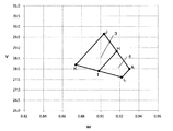
- composition range of the present invention it is an explanatory view showing the range of v and w when Ga is 0.40 mass% or more and 0.70 mass% or less. In one embodiment according to the composition range of the present invention, it is an explanatory view showing the range of v and w when Ga is 0.20 mass% or more and less than 0.40 mass%. It is explanatory drawing which shows the relative relationship between the range shown in FIG. 1, and the range shown in FIG. FIG. 4 is an explanatory diagram in which the values of v and w of each sample according to “ ⁇ Reference Example 1>” are plotted in FIG.
- the RTB-based sintered magnet in the method of forming, sintering, and heat-treating after mixing one or more additive alloy powders and one or more main alloy powders in a specific mixing amount , found that by making use of additional alloy powder thickness 0.12mm or less material alloy having a specific composition, the R-T-B based sintered magnet having a higher B r and a high H cJ obtained It is a thing.
- R-T-B based sintered magnet can be improved B r by increasing the existence ratio of R 2 T 14 B type compound as the main phase.
- R amount, T amounts although the B amount should brought close to the stoichiometric ratio of R 2 T 14 B type compound, R 2 T 14 B-type
- the amount of B for forming the compound is lower than the stoichiometric ratio, a soft magnetic R 2 T 17 phase is generated at the grain boundary, and H cJ is rapidly decreased.
- an RT-Ga phase is generated instead of the R 2 T 17 phase, and a decrease in H cJ can be prevented.
- the RTB -Ga phase also has some magnetism, which is considered to affect the grain boundary in the RTB -based sintered magnet, particularly mainly HcJ . It was found that the presence of a large amount of RT-Ga phase at the grain boundary existing between the two main phases (hereinafter sometimes referred to as “two-grain grain boundary”) hinders the improvement of HcJ . . It was also found that, along with the generation of the RT-Ga phase, an R-Ga phase and an R-Ga-Cu phase were generated at the two grain boundaries.
- the present inventors assumed that HcJ is improved by the presence of the R—Ga phase and the R—Ga—Cu phase at the two-grain boundary of the RTB -based sintered magnet.
- HcJ is improved by the presence of the R—Ga phase and the R—Ga—Cu phase at the two-grain boundary of the RTB -based sintered magnet.
- it is necessary to generate the R—T—Ga phase but a high H cJ is obtained. Assumed that it was necessary to keep the production amount low. If the generation of the RT-Ga phase can be suppressed as much as possible while generating the R—Ga phase and the R—Ga—Cu phase, especially at the two-grain grain boundary, the H cJ can be further improved. Assumed.
- the amount of R 2 T 17 phase generated can be reduced by setting the amounts of R and B within appropriate ranges. In addition to lowering, it is necessary to set the R amount and the Ga amount within an optimal range according to the amount of R 2 T 17 phase generated. However, part of R is consumed in combination with oxygen, nitrogen and carbon in the manufacturing process of RTB-based sintered magnets, so it is actually used for the R 2 T 17 phase and RT-Ga phase. The amount of R changes in the manufacturing process.
- the present inventors have determined that the amount of oxygen (mass%) in the RTB-based sintered magnet is ⁇ and the amount of nitrogen (mass by mass) from the R amount (u) as described in the first aspect. %) Is ⁇ , and the amount of carbon (mass%) is ⁇ .
- the value (v) obtained by subtracting 6 ⁇ + 10 ⁇ + 8 ⁇ the amount of R 2 T 17 phase or RT-Ga phase can be adjusted. I found out.
- the RTB-based sintered magnet in the method of forming, sintering, and heat-treating after mixing one or more additive alloy powders and one or more main alloy powders in a specific mixing amount
- the additive alloy powder having a specific composition is prepared using a raw material alloy having a thickness of 0.12 mm or less, and the additive alloy powder and the main alloy powder having a Ga content of 0.4% by mass or less are used. higher B r and R-T-B based sintered magnet having a high H cJ was found that the resulting.
- the composition of the additive alloy powder in the present invention has more R than the R 2 T 14 B stoichiometric composition of the RTB-based sintered magnet. Therefore, although the R 2 T 14 B compound is always generated during the production of the raw material alloy, other phases such as the RT 4 B 4 phase, the RT-Ga phase, the R-Ga phase, and the R-Ga-Cu phase are present. May be generated.
- raw material alloys of RTB-based sintered magnets are produced by a liquid quenching method, and there is a strong correlation between the cooling rate and the thickness of the alloy, and the cooling rate decreases as the thickness of the raw material alloy decreases. Get faster.
- the thickness of the raw alloy of the RTB-based sintered magnet is about 0.2 mm to 0.5 mm.
- the inventors found that when the cooling rate was increased to reduce the thickness of the raw material alloy to 0.12 mm or less, the generation of the RT 4 B 4 phase and the RT—Ga phase was remarkably suppressed. .
- the additive alloy powder contains more Ga than the main alloy powder, the amount of Ga in the main alloy powder can be suppressed. Therefore, the generation of the RT—Ga phase in the main alloy powder is also suppressed.
- the additive alloy powder and the main alloy powder the amount of RTB-Ga phase produced in the mixed alloy powder stage can be extremely reduced, and the RTB-based sintering finally obtained can be achieved.
- the amount of RT—Ga phase generated in the magnet can be further suppressed (than in the case of a single alloy).
- the technique described in Patent Document 1 since the oxygen content, the nitrogen content, and the carbon content are not considered with respect to the R content, it is difficult to suppress the generation amount of the R 2 T 17 phase or the R—T—Ga phase. is there.
- the technique described in Patent Document 1 improves HcJ by promoting the generation of the RT—Ga phase, and there is no technical idea of suppressing the amount of RT—Ga phase generated.
- Patent Document 1 in order to promote the generation of the R 2 T 17 phase that is the raw material of the RT-Ga phase, the amount of B is made lower than before, and the generation of the RT-Ga phase is promoted. In addition, since it is necessary to increase the amount of R, it is considered that the existence ratio of the main phase is greatly reduced and high Br is not obtained. Further, in Patent Document 1, there is no technical idea of mixing an additive alloy powder produced using a raw material alloy having a thickness of 0.12 mm or less and a main alloy powder.
- the RTB-based sintered magnet of the present invention may contain inevitable impurities.
- the effects of the present invention can be achieved even if inevitable impurities normally contained in didymium alloy (Nd—Pr), electrolytic iron, ferroboron, and the like are contained.
- Inevitable impurities include, for example, trace amounts of La, Ce, Sm, Cr, Mn, Si, Ca, Mg and the like.
- the R-T-B based sintered magnet by the composition represented by the above formula it is possible to obtain the effect of high B r and high H cJ are obtained.
- the composition will be described in detail below.
- R is at least one of rare earth elements and necessarily contains Nd.
- the amount of heavy rare earth elements such as Dy and Tb is preferably 5% by mass or less of the RTB-based sintered magnet. Because the present invention can obtain a high B r and high H cJ without using a heavy rare-earth element, it can be reduced the amount of RH even be asked a higher H cJ.
- T is Fe, and 10% or less of Fe by mass ratio can be substituted with Co.
- B is boron.
- the oxygen content (mass%), nitrogen content (mass%), and carbon content (mass%) are the contents in the RTB system sintered magnet (that is, RTB system magnet).
- Content when the total mass is 100% by mass) oxygen amount is gas melting-infrared absorption method
- nitrogen amount is gas melting-heat conduction method
- carbon amount is combustion-infrared absorption method It can be measured using a gas analyzer.
- the present invention uses a value (v) obtained by subtracting the amount consumed by combining with oxygen, nitrogen and carbon from the amount of R (u) by the method described below. This makes it possible to adjust the amount of R 2 T 17 phase or RT-Ga phase generated.
- the v is determined by subtracting 6 ⁇ + 10 ⁇ + 8 ⁇ from the R amount (u), where ⁇ is the oxygen amount (% by mass), ⁇ is the nitrogen amount (% by mass), and ⁇ is the carbon amount (% by mass).
- 6 ⁇ is defined because R having a mass approximately six times that of oxygen is consumed as an oxide, assuming that an oxide of R 2 O 3 is mainly produced as an impurity.
- 10 ⁇ is defined by the fact that R having a mass approximately 10 times that of nitrogen is consumed as nitride, assuming that RN nitride is mainly produced.
- 8 ⁇ is defined because R, which is approximately eight times the mass of carbon, is consumed as carbides, assuming that R 2 C 3 carbides are mainly produced.
- the oxygen amount, the nitrogen amount, and the carbon amount are obtained by measurement using the above-described gas analyzer, whereas each of R, B, Ga, Cu, Al, and M shown in the formula (1) is used.
- the contents (mass%) u, w, x, y, z, and q may be measured using inductively coupled plasma emission spectroscopy (ICP emission spectroscopy). Further, 100-uwxyzzq may be obtained by calculation using measured values of u, w, x, y, z, and q obtained by ICP emission spectroscopy. Further, equation (1) can be measured by ICP emission spectrometry, but oxygen, nitrogen and carbon cannot be measured by ICP emission spectrometry.
- u, w, x, y, z, q and 100-uwxyy defined by the formula (1) are used.
- the sum of zq, oxygen content ⁇ , nitrogen content ⁇ and carbon content ⁇ is allowed to exceed 100 mass%.
- the amount of oxygen in the RTB-based sintered magnet is preferably 0.15% by mass or less. Since v is a value obtained by subtracting 6 ⁇ + 10 ⁇ + 8 ⁇ from the R amount (u), assuming that the oxygen amount (mass%) is ⁇ , the nitrogen amount (mass%) is ⁇ , and the carbon amount (mass%) is ⁇ , for example, the oxygen amount ⁇ is When there are many, it is necessary to increase R amount in the raw material alloy stage. In particular, out of regions 1 and 2 according to one embodiment of the present invention in FIG. 1 to be described later, region 1 has a relatively higher v than region 2, so that when the amount of oxygen ⁇ is large, at the stage of the raw material alloy The amount of R may be very large. As a result, the abundance ratio of the main phase is lowered and Br may be lowered. In particular, in the region 1 of the present invention shown in FIG. 1, the oxygen amount is preferably 0.15% by mass or less.
- Ga is 0.20 mass% or more and 0.70 mass% or less. However, when Ga is 0.40 mass% or more and 0.70 mass% or less and when it is 0.20 mass% or more and less than 0.40 mass%, the ranges of v and w are different. This will be described in detail below.
- v and w when Ga is 0.40% by mass or more and 0.70% by mass or less, v and w have the following relationship. 50w-18.5 ⁇ v ⁇ 50w-14 (6) ⁇ 12.5w + 38.75 ⁇ v ⁇ ⁇ 62.5w + 86.125 (7)
- FIG. 1 shows the range of v and w that satisfies the above equations (6) and (7).
- v is a value obtained by subtracting 6 ⁇ + 10 ⁇ + 8 ⁇ from the R amount (u), where the oxygen amount (% by mass) is ⁇ , the nitrogen amount (% by mass) is ⁇ , and the carbon amount (% by mass) is ⁇ .
- B value the oxygen amount (% by mass) is ⁇ .
- Equation (6) that is, 50w-18.5 ⁇ v ⁇ 50w-14, is a straight line including points A and B (a straight line connecting points A and B) and a straight line including points C and D (points) in FIG. (Straight line connecting C and point D), and formula (7), that is, ⁇ 12.5w + 38.75 ⁇ v ⁇ ⁇ 62.5w + 86.125, points D, F, B and G This is a range between the straight line including the straight line including the point C, the point E, the point A, and the point G. Regions 1 and 2 (regions surrounded by point A, point B, point D, and point C) that satisfy both of these are the ranges according to one aspect of the present invention.
- the region 10 deviated from the range of the regions 1 and 2 (the lower region in the figure from the straight line including the point D, the point F, the point B, and the point G) has too little v with respect to w, so the RT-Ga phase It is considered that the production amount of R 2 T 17 cannot be eliminated, and the production amounts of the R—Ga phase and the R—Ga—Cu phase are reduced. Thereby, high HcJ cannot be obtained.
- the region 20 outside the range of the regions 1 and 2 (the region in the figure from the straight line including the point C, the point E, the point A, and the point G) has too many vs relative to w. Insufficient Fe content. If the amount of Fe is insufficient, R and B will remain, and as a result, the R 1 Fe 4 B 4 phase is likely to be generated without generating the RT-Ga phase. As a result, the amount of R-Ga phase and R-Ga-Cu phase produced is reduced, and high HcJ cannot be obtained.
- the region 30 (the region in the figure from the straight line including the points C and D) deviated from the range of the regions 1 and 2 has too much v and too little w, so that the RT-Ga phase or R Although a —Ga phase and an R—Ga—Cu phase are produced, the abundance ratio of the main phase is lowered, and high Br cannot be obtained.
- the region 40 (the region excluding the regions 1 and 2 from the region surrounded by the points C, D, and G) that is out of the range of the regions 1 and 2 has a small amount of R and a large amount of B. Although the abundance ratio is high, the R—T—Ga phase is hardly generated, and the generation amount of the R—Ga phase and the R—Ga—Cu phase is reduced, so that high H cJ cannot be obtained.
- v and w are in the following relationship. 50w-18.5 ⁇ v ⁇ 50w-15.5 (8) ⁇ 12.5w + 39.125 ⁇ v ⁇ ⁇ 62.5w + 86.125 (9)
- FIG. 2 shows the scope of the present invention for v and w satisfying equations (8) and (9).
- Expression (8) that is, 50w-18.5 ⁇ v ⁇ 50w ⁇ 15.5 is a range between the straight line including the point A and the point L and the straight line including the point J and the point K in FIG.
- FIG. 3 shows the position of FIG. 1 (when Ga is 0.40 mass% or more and 0.70 mass% or less) and FIG. 2 (when Ga is 0.20 mass% or more and less than 0.40 mass%).
- the relationship (relative relationship between the range shown in FIG. 1 and the range shown in FIG. 2) is shown.
- x is in the range of the following formula (10) according to v and w. ⁇ (62.5w + v ⁇ 81.625) /15+0.5 ⁇ x ⁇ (62.5w + v ⁇ 81.625) /15+0.8 (10)
- x is in the range of the following formula (10) according to v and w.
- ⁇ (62.5w + v ⁇ 81.625) /15+0.5 ⁇ x ⁇ (62.5w + v ⁇ 81.625) /15+0.8 (10)
- FIG. 1 shows the range of v and w that satisfies the above equations (19) and (7).
- Equation (19) that is, 50w-18.5 ⁇ v ⁇ 50w-16.25, is a range sandwiched between a straight line including point A and point B and a straight line including point E and point F.
- Equation (7) That is, ⁇ 12.5w + 38.75 ⁇ v ⁇ ⁇ 62.5w + 86.125 is sandwiched between a straight line including point D, point F, point B, and point G, and a straight line including point C, point E, point A, and point G. It is a range. And the area
- region 2 (area
- FIG. 2 shows a range that satisfies the above equations (20) and (9).
- Expression (20) that is, 50w-18.5 ⁇ v ⁇ 50w ⁇ 17.0 is a range sandwiched between a straight line including point A and point L and a straight line including point H and point I
- expression (9) That is, ⁇ 12.5w + 39.125 ⁇ v ⁇ ⁇ 62.5w + 86.125 is a range sandwiched between a straight line including point K, point I and point L, and a straight line including point J, point H and point A.
- region 4 area
- FIG. 3 shows a relative range of FIG.
- FIG. 1 (Ga is 0.40 mass% or more and 0.70 mass% or less) and FIG. 2 (Ga is 0.20 mass% or more and less than 0.40 mass%).
- x is ⁇ (62.5w + v ⁇ 81.625) /15+0.5 ⁇ x ⁇ ( 62.5w + v ⁇ 81.625) /15+0.8
- the amount of RT-Ga phase can be secured while v can be lowered and w can be increased.
- the ratio is not lowered, and a higher Br can be obtained.
- the Cu content is more preferably 0.08% by mass or more and 0.15% by mass or less.
- Al 0.05 mass% or more and 0.5 mass% or less
- HcJ HcJ
- Al is usually contained in an amount of 0.02% by mass or more as an inevitable impurity in the production process, but it may be contained in an amount of 0.5% by mass or less in total of the amount of the inevitable impurity and the amount intentionally added. Good.
- an RTB-based sintered magnet contains Nb, Zr, and Ti to suppress abnormal grain growth during sintering.
- Nb, Zr, and Ti may be contained in a total amount of 0.3% by mass or less.
- the R—T—Ga phase includes R: 15% by mass to 65% by mass, T: 20% by mass to 80% by mass, Ga: 2% by mass to 20% by mass.
- the R 6 Fe 13 Ga compound may be an R 6 T 13- ⁇ Ga 1 + ⁇ compound depending on the state.
- the RT-Ga phase may contain Al, Cu, and Si as unavoidable impurities, for example, an R 6 Fe 13 (Ga 1-x-yz Cu x Al y Si z ) compound is included. It may be.
- the R—Ga phase includes R: 70% by mass or more and 95% by mass or less, Ga: 5% by mass or more and 30% by mass or less, and T (Fe): 20% by mass or less (including 0). Examples thereof include R 3 Ga compounds. Further, the R—Ga—Cu phase is one in which part of Ga in the R—Ga phase is substituted with Cu, and examples thereof include R 3 (Ga, Cu) 1 compounds.
- R-T-B based sintered magnet having a high B r and high H cJ be manufactured by a known manufacturing method
- a known manufacturing method can be obtained.
- an additive alloy powder having a specific composition prepared using a raw material alloy having a thickness of 0.12 mm or less, and a main alloy powder having a Ga content of 0.4 mass% or less it can be obtained R-T-B based sintered magnet having a higher B r and a high H cJ.
- an example of a known manufacturing method will be described below, and then the manufacturing method of the present invention will be described.
- the known production method comprises a step of obtaining an alloy powder, a forming step, a sintering step, and a heat treatment step. Hereinafter, each step will be described.
- Step of obtaining alloy powder A metal or alloy of each element is prepared so as to have a predetermined composition, and these are flaked raw material alloy having a thickness of about 0.2 to 0.5 mm by using a strip casting method or the like. Manufacturing.
- the obtained flaky raw material alloy is hydrogen pulverized so that the size of the coarsely pulverized powder is 1.0 mm or less, for example.
- the coarsely pulverized powder is finely pulverized by a jet mill or the like, so that, for example, finely pulverized powder (single alloy powder) having a particle diameter D50 (volume-based median diameter obtained by a laser diffraction method using an air flow dispersion method) of 3 to 7 ⁇ m )
- a known lubricant may be used as an auxiliary agent for the coarsely pulverized powder before jet mill pulverization and the alloy powder during and after jet mill pulverization.
- Forming step Using the obtained alloy powder (single alloy powder or mixed alloy powder), forming in a magnetic field to obtain a compact.
- Molding in a magnetic field is a dry molding method in which a dry alloy powder is inserted into a mold cavity and molding is performed while a magnetic field is applied.
- Any known molding method in a magnetic field may be used, including a wet molding method in which molding is performed while the slurry dispersion medium is discharged.
- a sintered compact is obtained by sintering a molded object.
- a well-known method can be used for sintering of a molded object.
- sintering is preferably performed in a vacuum atmosphere or an inert gas atmosphere.
- the inert gas helium, argon or the like is preferably used.
- the obtained sintered body is preferably subjected to heat treatment for the purpose of improving magnetic properties.
- heat treatment temperature can be adopted for the heat treatment temperature, the heat treatment time, and the like.
- the obtained sintered magnet may be subjected to machining such as grinding in order to adjust the magnet dimensions. In that case, the heat treatment may be performed before or after machining.
- the surface treatment may be a known surface treatment, and for example, a surface treatment such as Al vapor deposition, electric Ni plating, or resin coating can be performed.
- the additive alloy powder is produced using a raw material alloy having a thickness of 0.12 mm or less having the following composition.
- the raw material alloy having a thickness of 0.12 mm or less is an average value obtained by measuring 100 dimensions in the thickness direction of the obtained raw material alloy.
- a raw material alloy having a thickness of 0.12 mm or less is produced, for example, using the following method. For example, there is a melt spinning method as disclosed in JP-A-2-179803.
- a molten alloy is jetted onto a rotating cooling roll from a nozzle having an inner diameter of 1 mm or less at the bottom, and this is rapidly cooled to produce a ribbon-like solidified alloy.
- molten alloy melted in a melting furnace is poured into a container having an injection nozzle at the bottom, and then the molten metal is applied from the nozzle to the surface of the rotating roll by applying a certain pressure to the molten metal in the container. It is sprayed towards.
- the injected molten metal forms a hot water pool (paddle) on the surface of the cooling roll rotating at a relatively high speed, and the roll contact surface of the paddle is quenched to produce a ribbon-like quenched alloy.
- Another method is a straight-tube strip casting method as disclosed in JP-A-2004-122230.
- the molten metal can be rectified on the inclined molten metal guide surface and the molten metal can be supplied through a tubular hole having a relatively large opening area at the tip, no back pressure is applied to the molten metal ( Although the force causing the movement of the molten metal is only in the state of gravity), the molten metal can be supplied to the roll surface with a large momentum, so that the alloy can be cooled at a cooling rate close to the melt spinning method.
- composition of the additive alloy powder is Formula: aRbBcGadCueAlfM (100-abbcddf) T (11) Represented by 32 ⁇ a ⁇ 66 (12) 0.3 ⁇ b ⁇ 0.9 (13) 0.7 ⁇ c ⁇ 12 (14) 0 ⁇ d ⁇ 4 (15) 0 ⁇ e ⁇ 10 (16) 0 ⁇ f ⁇ 10 (17) Remainder T (R is at least one kind of rare earth element, T is Fe and 10% by mass or less of Fe can be substituted with Co, and M is at least one kind of Nb, Zr, and Ti. A, b, c, d, e, f and 100-abc-c-d-f represents mass%).
- the additive alloy powder has a relatively higher R than the R 2 T 14 B stoichiometric composition. Therefore, the generation of the RT 4 B 4 phase and the RT-Ga phase is suppressed by setting the thickness of the raw material alloy to 0.12 mm or less.
- the R 2 T 14 B phase, the R—Ga phase, and the R—Ga are suppressed.
- a raw material alloy mainly containing a Cu phase can be obtained.
- the additive alloy powder may contain inevitable impurities. For example, the effects of the present invention can be achieved even if inevitable impurities normally contained in didymium alloy (Nd—Pr), electrolytic iron, ferroboron, and the like are contained.
- Inevitable impurities include, for example, trace amounts of La, Ce, Sm, Cr, Mn, Si, Ca, Mg and the like. If R (a) is less than 32% by mass, the R amount is relatively small relative to the R 2 T 14 B stoichiometric composition, so that there is a possibility that the R—Ga phase is difficult to be produced. If the amount exceeds R, the amount of R is too large, which may cause oxidation problems, leading to deterioration of magnetic properties and risk of ignition, which may cause production problems. If B (b) is less than 0.3% by mass, the amount of B is relatively small with respect to the R 2 T 14 B stoichiometric composition, so that an RT-Ga phase may be easily formed. .
- the additive alloy powder has a Ga content higher than that of the main alloy powder. This is because if the Ga content of the additive alloy powder is lower than that of the main alloy powder, it may not be possible to suppress the generation of the RT—Ga phase in the main alloy powder.
- the additive alloy powder may be a kind of alloy powder or may be composed of two or more kinds of alloy powders having different compositions. When two or more kinds of additive alloy powders are used, all of the additive alloy powders are within the above composition range.
- the Ga content of the main alloy powder is 0.4% by mass or less, and an arbitrary composition adjusted to be an RTB-based sintered magnet having the composition of the present invention by mixing with the additive alloy powder.
- the main alloy powder is prepared with When the Ga content of the main alloy powder exceeds 0.4% by mass, the main alloy powder may not be able to suppress the formation of the RT—Ga phase in the main alloy powder.
- the main alloy powder may be a kind of alloy powder or may be composed of two or more kinds of alloy powders having different compositions.
- Step of obtaining mixed alloy powder One or more additive alloy powders having the composition described above and one or more main alloy powders are mixed to obtain a mixed alloy powder.
- the mixing amount of the additive alloy powder in the mixed alloy powder is in the range of 0.5 to 10 parts by mass with respect to 100 parts by mass in total of the additive alloy powder and the main alloy powder.
- R-T-B based sintered magnet of the mixing amount of the additive alloy powder was prepared in the above range, it is possible to obtain a higher B r and a high H cJ. If the mixed amount of the additive alloy powder is less than 0.5 parts by mass, the effect of the present invention may not be obtained because the additive alloy powder is too small. If the amount exceeds 10 parts by mass, the degree of orientation decreases. There is a concern that Br may be lowered.
- the mixed alloy powder is molded, the molded body is sintered, and the sintered body is subjected to heat treatment.
- the molding process, the sintering process, and the heat treatment process are the same as the known manufacturing methods described above.
- the obtained RTB system sintered magnet may be subjected to machining such as grinding in order to adjust the magnet dimensions.
- the high temperature heat treatment step and the low temperature heat treatment step may be performed before or after machining.
- the surface treatment may be a known surface treatment, and for example, a surface treatment such as Al deposition, electric Ni plating or resin coating can be performed.
- the resulting coarsely pulverized powder is dried in a nitrogen stream using a jet mill device.
- a finely pulverized powder (alloy powder) having a particle diameter D50 of 4 ⁇ m was obtained.
- the oxygen concentration in the nitrogen gas during pulverization was adjusted by mixing the atmosphere with nitrogen gas during pulverization. When the atmosphere is not mixed, the oxygen concentration in the nitrogen gas during pulverization is 50 ppm or less.
- the particle diameter D50 is a volume-based median diameter obtained by a laser diffraction method using an air flow dispersion method.
- Table 1 a gas analyzer using the gas melting-infrared absorption method for O (oxygen amount), gas melting-heat conduction method for N (nitrogen amount), and combustion-infrared absorption method for C (carbon amount) is used. Measured.
- the obtained molded body was sintered in vacuum at 1020 ° C. for 4 hours and then rapidly cooled to obtain an RTB-based sintered magnet.
- the density of the sintered magnet was 7.5 Mg / m 3 or more.
- Table 1 shows the results of measuring the contents of Nd, Pr, Dy, Tb, B, Co, Al, Cu, Ga, Nb, and Zr by ICP emission spectroscopy in order to determine the components of the obtained sintered magnet. Shown in The balance (the balance obtained by subtracting the contents of Nd, Pr, Dy, Tb, B, Co, Al, Cu, Ga, Nb, and Zr obtained by measurement from 100% by mass) was defined as the Fe content. . Further, Table 1 shows the gas analysis results (O, N, and C).
- the sintered body was heated at 800 ° C. for 2 hours and then cooled to room temperature, and then held at 500 ° C. for 2 hours and then cooled to room temperature.
- vertical 7 mm, transverse 7 mm, to prepare a sample having a thickness of 7 mm were measured B r and H cJ of the sample by B-H tracer. The measurement results are shown in Table 2.
- u is a value obtained by summing the amounts of Nd, Pr, Dy, and Tb in Table 1
- v is an oxygen amount (% by mass) in Table 1
- ⁇ is a nitrogen amount (% by mass), and carbon.
- w the amount of B in Table 1 is directly transferred.
- the amounts of Nd, Pr, Dy, and Tb are omitted from the numerical values shown in Table 1 because the numerical values below the numerical values shown are omitted. And may be slightly different. The same applies to the numerical values of u and v in the table described below.
- the area in Table 2 indicates where v and w are in FIG. 1.
- the area When the area is 1 in FIG. 1, the area is 1 and 2 in FIG. 1. The case was described as 2. Furthermore, when it exists in the area
- composition shown in Aspect 1 or 2 the composition of the RTB-based sintered magnet shown in Aspect 1 or Aspect 2 (hereinafter sometimes simply referred to as “Composition shown in Aspect 1 or 2”).
- the case of being within the range is described as “ ⁇ ”, and the case of being outside the composition range is described as “x”.
- FIG. 4 is an explanatory diagram in which the values of v and w are plotted for the reference example sample that is within the composition range and the reference example sample that is outside the composition range shown in FIG. It can be easily understood from FIG. 4 that the sample within the composition range is in the range of the region 1 or 2, and the sample outside the composition range is outside the range of the region 1 and 2.
- the composition shown in the aspect 1 or 2 contains v and w in the following ratios when x is 0.40 mass% or more and 0.70 mass% or less.
- the range of v and w when contained in the ratio corresponds to the region 1 and 2 or 2 in FIG.
- Sample No. 08 is the composition range of Ga shown in the embodiment 1 or 2 when Ga is 0.20% by mass or more and less than 0.40% by mass ( ⁇ (62.5w + v ⁇ 81.625) /15+0.5 ⁇ x (Ga) ⁇ ⁇ (62.5w + v ⁇ 81.625) /15+0.8), it is not possible to generate the minimum RT-Ga phase necessary for obtaining high magnetic properties, so that H cJ is It is thought that it has greatly decreased.
- H cJ can be increased.
- B r decreases approximately 0.024T when containing 1 mass% of Dy and Tb.
- HcJ increases by about 160 kA / m when 1% by mass of Dy is contained, and increases by about 240 kA / m when 1% by mass of Tb is contained. Therefore, within the composition range shown in the aspect 1 or 2, when the raw material alloy does not contain Dy and Tb as described above, the magnetic properties are B r ⁇ 1.340T and H cJ ⁇ 1300 kA / m.
- Ga 55 represents the composition range of Ga shown in the embodiment 1 or 2 when Ga is 0.20% by mass or more and less than 0.40% by mass ( ⁇ (62.5w + v ⁇ 81.625) /15+0.5 ⁇ x (Ga) ⁇ ⁇ (62.5w + v ⁇ 81.625) /15+0.8), it is not possible to generate the minimum RT-Ga phase necessary for obtaining high magnetic properties, so that H cJ is It is thought that it has greatly decreased.
- the region 2 (region 2 in FIG. 1) is higher than the region 1 (region 1 in FIG. 1) within the composition range shown in the embodiment 1 or 2.
- B r (when the raw material alloy does not contain Dy and Tb, B r ⁇ 1.360T, when it contains Dy and Tb, B r ⁇ 1.360T ⁇ 0.024 [Dy] ⁇ 0.024 [Tb])
- [Dy] [Tb] indicates the content (% by mass) of Dy and Tb, respectively.
- the particle diameter D50 is a volume-based median diameter obtained by a laser diffraction method using an air flow dispersion method.
- O oxygen amount
- N nitrogen amount
- C carbon amount
- U in Table 4 is a value obtained by summing the amounts (mass%) of Nd, Pr, Dy, and Tb in Table 3, and v is ⁇ and nitrogen quantity (mass%) in Table 3. Is the value obtained by subtracting 6 ⁇ + 10 ⁇ + 8 ⁇ from u, where ⁇ is ⁇ and the carbon content (% by mass) is ⁇ .
- w the amount of B in Table 3 was directly transferred.
- the area in Table 4 shows where v and w are in FIG. 2, where 3 is in the area 3 in FIG. 2 and 4 is in the area in FIG. It was described as 4.
- “/” is shown when the area is outside the areas 3 and 4 in FIG.
- the case where it is within the composition range shown in the aspect 1 or 2 was described as “ ⁇ ”, and the case where it was outside the composition range was described as “X”.
- Each of the reference example samples is B r ⁇ 1.377T and H cJ ⁇ 1403 kA / m, and the sample within the composition range shown in the embodiment 1 or 2 of the reference example 1 (the composition in FIGS. (Comparative Example 1 is compared with Reference Example 1) regardless of the amount of Ga (reference example 1 is x (Ga) 0.40% by mass or more). High magnetic properties equivalent to or better than that. On the other hand, even if the amounts of Ga, Cu, and Al are within the composition range shown in aspect 1 or 2, v and w are outside the composition range shown in aspect 1 or 2 (regions other than 3 or 4 in FIG. 2). Sample No. Comparative Sample No.
- 87, 88, and v and w are within the composition range shown in Embodiment 1 or 2 (region 3 or 4 in FIG. 2) but Ga is outside the composition range shown in Embodiment 1 or 2 .
- No. 89 has high magnetic properties such as B r ⁇ 1.377 T and H cJ ⁇ 1403 kA / m.
- Example 1 Using Nd metal, Pr metal, Dy metal, ferroboron alloy, electrolytic Co, Al metal, Cu metal, Ga metal, ferroniobium alloy, ferrozirconium alloy, Ti metal and electrolytic iron as raw materials (all metals have a purity of 99% or more)
- the raw materials were blended and dissolved so as to have the composition shown in Table 5 to prepare a raw alloy of the main alloy powder and a raw alloy of the additive alloy powder.
- the raw alloy of the main alloy powder was cast by a strip casting method to obtain a flaky raw alloy having a thickness of 0.2 to 0.5 mm.
- the raw material alloy of the additive alloy powder was produced by the melt spinning method described above.
- the raw material was melted at a high frequency in a quartz nozzle having an orifice diameter of 0.8 mm in a chamber having an argon atmosphere of 80 kPa, and then a back pressure of 100 kPa was applied to inject the molten metal onto the Cu roll. .
- the circumferential speed of the Cu roll was 10 to 40 m / s depending on the composition.
- 100 dimensions in the thickness direction of the obtained raw material alloy were measured to obtain an average value. The average value was between 0.075 and 0.084 mm depending on the composition.
- the obtained raw material alloy (the raw material alloy used for the main alloy powder and the raw material alloy used for the additive alloy powder) is hydrogen embrittled in a hydrogen-pressurized atmosphere and then heated and cooled to 550 ° C. in a vacuum.
- Raw treatment was performed to obtain coarsely pulverized powder.
- the obtained coarsely pulverized powder of the additive alloy and the coarsely pulverized powder of the main alloy were put into a V-type mixer in the mixing amounts shown in Table 6 and mixed to obtain mixed alloy powder.
- the resulting mixed alloy powder is dry-ground in a nitrogen stream using a jet mill device, and then granulated.
- a mixed alloy powder having a finely pulverized powder with a diameter D50 of 4 ⁇ m was obtained.
- the oxygen concentration in the nitrogen gas during pulverization was adjusted by mixing the atmosphere with nitrogen gas during pulverization. When the atmosphere is not mixed, the oxygen concentration in the nitrogen gas during pulverization is 50 ppm or less, and by mixing the air, the oxygen concentration in the nitrogen gas is increased to a maximum of 5500 ppm to produce finely pulverized powders with various oxygen amounts.
- the particle diameter D50 is a volume-based median diameter obtained by a laser diffraction method using an air flow dispersion method. Further, O (oxygen amount), N (nitrogen amount), and C (carbon amount) in Table 7 were measured in the same manner as in Reference Example 1.
- finely pulverized powder obtained by mixing additive alloy powder and main alloy powder
- a molded body was produced by the same method as in Reference Example 1, and further sintered and heat-treated by the same method as in Reference Example 1.
- Table 7 shows the composition of the obtained RTB-based sintered magnet. By machining the sintered magnet after the heat treatment was measured B r and H cJ of each sample in the same manner as in Reference Example 1.
- Table 8 shows the measurement results.
- Sample No. in Table 7 100 RTB-based sintered magnets use a mixed alloy powder obtained by mixing the A alloy powder (addition alloy powder) and the A-1 alloy powder (main alloy powder) shown in Table 5 in the mixing amount shown in Table 6. 4 parts by mass of the additive alloy powder (A alloy powder) with respect to 100 parts by mass in total of the additive alloy powder (A alloy powder) and the main alloy powder (A-1 alloy powder). A mixed alloy powder of the additive alloy powder and the main alloy powder is used. Sample No. 101 to 135 are also described in a similar manner. Moreover, u in Table 8 is the total value of the amounts of Nd, Pr, and Dy in Table 7, and v is ⁇ , nitrogen amount (mass%) is ⁇ , carbon is oxygen content (mass%) in Table 7.
- the production method of the present invention (additional alloy powder having the composition of the present invention produced using a raw material alloy having a thickness of 0.12 mm or less and a Ga content of 0.4 mass% or less A main alloy powder is prepared, and the additive alloy powder and the main alloy powder are included in an amount of 0.5 to 10 parts by mass with respect to a total of 100 parts by mass of the additive alloy powder and the main alloy powder.
- Sample No. 2 produced within the composition range shown in the embodiment 1 or 2 is used. 100-125 and sample no. 133 to 135, when Dy and Tb are not contained in the raw material alloy (the present invention other than Sample Nos.
- Example 2 Additive alloy powder using Nd metal, Pr metal, ferroboron alloy, electrolytic Co, Al metal, Cu metal, Ga metal, and electrolytic iron (all metals have a purity of 99% or more) to have the composition shown in Table 9
- the main alloy powder was blended, and the main alloy powder was melted and cast by a strip casting method to obtain a flaky raw material alloy having a thickness of 0.3 to 0.4 mm.
- the additive alloy powder was produced by the melt spinning method under the same conditions as in Example 1. Each of the obtained raw material alloys was measured for 100 dimensions in the thickness direction, and the average value was obtained. The average value was between 0.075 and 0.082 mm depending on the composition.
- Each of the obtained raw material alloys was hydrogen embrittled in a hydrogen-pressurized atmosphere, and then subjected to dehydrogenation treatment by heating and cooling to 550 ° C. in a vacuum to obtain coarsely pulverized powder.
- the obtained coarsely pulverized powder of the additive alloy and the coarsely pulverized powder of the main alloy were put into a V-type mixer in the mixing amount shown in Table 10 and mixed to obtain mixed alloy powder.
- the resulting mixed alloy powder is dry-ground in a nitrogen stream using a jet mill device, and then granulated.
- a mixed alloy powder having a finely pulverized powder with a diameter D50 of 4 ⁇ m was obtained.
- the oxygen concentration in the nitrogen gas during pulverization was adjusted by mixing the atmosphere with nitrogen gas during pulverization. When the atmosphere is not mixed, the oxygen concentration in the nitrogen gas during pulverization is 50 ppm or less. By mixing the air, the oxygen concentration in the nitrogen gas is increased to a maximum of 1600 ppm, and finely pulverized powders with various oxygen amounts are produced. did.
- the particle diameter D50 is a volume-based median diameter obtained by a laser diffraction method using an air flow dispersion method. In Table 11, O (oxygen amount), N (nitrogen amount), and C (carbon amount) were measured in the same manner as in Reference Example 1.
- finely pulverized powder obtained by mixing additive alloy powder and main alloy powder
- a molded body was produced by the same method as in Reference Example 1, and further sintered and heat-treated by the same method as in Reference Example 1.
- Table 11 shows the composition of the obtained RTB-based sintered magnet. By machining the sintered magnet after the heat treatment was measured B r and H cJ of each sample in the same manner as in Reference Example 1.
- Table 12 shows the measurement results.
- Table 10 shows RTB-based sintered magnets of Table 9.
- M alloy powder (addition alloy powder), M-1 alloy powder (main alloy powder) and M-2 alloy powder (main alloy powder) in Table 9 are shown in Table 10.
- the mixed alloy powder was mixed at the indicated mixing amount, and the mixing amount was a total of 100 of the additive alloy powder (M alloy powder) and the main alloy powder (M-1 and M-2 alloy powder).
- Sample No. 141 and 142 are also described in a similar manner.
- u in Table 12 is a value obtained by totaling the amounts of Nd, Pr, and Dy in Table 11, and v is ⁇ , nitrogen amount (mass%) is ⁇ , carbon is oxygen content (mass%) in Table 11.
- v is ⁇
- nitrogen amount (mass%) is ⁇
- carbon is oxygen content (mass%) in Table 11.
- w the amount of B in Table 11 is directly transferred.
- the region in Table 12 indicates where v and w are in FIG. 1, and is in region 1 in FIG. 1 and region 2 in FIG. The case was described as 2.
- the composition of the additive alloy powder and the main alloy powder shown in Table 9, the mixing amount of the additive alloy powder shown in Table 10, and the composition of the RTB system sintered magnet shown in Table 11 are all within the scope of the present invention. It is.
- sample No. 1 was prepared by mixing one kind of additive alloy powder and two kinds of main alloy powders to produce an RTB-based sintered magnet.
- B r ⁇ 1.378T and H cJ ⁇ 1536 kA / m which are higher than those of Reference Examples 1 and 2, and can provide higher B r and higher H cJ .
- Example 3 Additive alloy powder using Nd metal, Pr metal, ferroboron alloy, electrolytic Co, Al metal, Cu metal, Ga metal, and electrolytic iron (all metals have a purity of 99% or more) to have the composition shown in Table 13
- the main alloy powder was blended, and the main alloy powder was melted and cast by a strip casting method to obtain a flaky raw material alloy having a thickness of 0.3 to 0.4 mm.
- the additive alloy powder two types of thickness of the raw material alloy (average value obtained by measuring 100 dimensions in the thickness direction of the raw material alloy) by the melt spinning method (the alloy powder N in Table 13 has a thickness of 0.1 mm).
- the alloy powder NA in Table 13 was a 0.02 mm thick material alloy).
- Each of the obtained raw material alloys was hydrogen embrittled in a hydrogen-pressurized atmosphere, and then subjected to dehydrogenation treatment by heating and cooling to 550 ° C. in a vacuum to obtain coarsely pulverized powder.
- the obtained coarsely pulverized powder of the additive alloy and the coarsely pulverized powder of the main alloy were put into a V-type mixer in the mixing amount shown in Table 14 and mixed to obtain mixed alloy powder.
- the resulting mixed alloy powder is dry-ground in a nitrogen stream using a jet mill device, and then granulated.
- a mixed alloy powder having a finely pulverized powder with a diameter D50 of 4 ⁇ m was obtained.
- the oxygen concentration in the nitrogen gas during pulverization was adjusted by mixing the atmosphere with nitrogen gas during pulverization. When the atmosphere is not mixed, the oxygen concentration in the nitrogen gas during pulverization is 50 ppm or less, and by mixing the air, the oxygen concentration in the nitrogen gas is increased to a maximum of 1100 ppm to produce finely pulverized powders with various oxygen amounts. did.
- the particle diameter D50 is a volume-based median diameter obtained by a laser diffraction method using an air flow dispersion method. Further, O (oxygen amount), N (nitrogen amount), and C (carbon amount) in Table 15 were measured in the same manner as in Reference Example 1.
- finely pulverized powder obtained by mixing additive alloy powder and main alloy powder
- a molded body was produced by the same method as in Reference Example 1, and further sintered and heat-treated by the same method as in Reference Example 1.
- Table 15 shows the composition of the obtained RTB-based sintered magnet. By machining the sintered magnet after the heat treatment was measured B r and H cJ of each sample in the same manner as in Reference Example 1. The measurement results are shown in Table 16.
- Table 14 shows the RTB-based sintered magnet of No. 145.
- Table 14 shows the N alloy powder (addition alloy powder), N-1 alloy powder (main alloy powder) and N-2 alloy powder (main alloy powder) of Table 13.
- the mixed alloy powder was mixed at the indicated mixing amount, and the mixing amount was 100 mass in total of the additive alloy powder (N alloy powder) and the main alloy powder (N-1 and N-2 alloy powder).
- the additive alloy powder (N) is 4 parts by mass
- the main alloy powder (N-1) is 48 parts by mass
- the main alloy powder (N-2) is 48 parts by mass.
- u in Table 16 is a value obtained by summing the amounts of Nd, Pr, and Dy in Table 15, and v is the amount of oxygen (mass%) in Table 15 by ⁇ and the amount of nitrogen ( The value obtained by subtracting 6 ⁇ + 10 ⁇ + 8 ⁇ from u, where ⁇ is the mass%) and ⁇ is the carbon mass (mass%).
- the w is the same as the amount of B in Table 15.
- the region in Table 16 indicates where v and w are in FIG. 1 and 2 in the region of Fig. 1.
- the composition of the additive alloy powder and the main alloy powder shown in Table 13 the mixing amount and table of the additive alloy powder shown in Table 14
- the composition of the RTB-based sintered magnet shown in 15 is all within the scope of the present invention.
- an RTB-based sintered magnet was prepared by mixing one kind of additive alloy powder and two kinds of main alloy powders. As for 145 to 148, B r ⁇ 1.378T and H cJ ⁇ 1536 kA / m, which are higher than those of Reference Examples 1 and 2, and can provide higher B r and higher H cJ .
- the RTB-based sintered magnet according to the present invention can be suitably used for motors for electric vehicles and motors for industrial equipment.
Landscapes
- Engineering & Computer Science (AREA)
- Chemical & Material Sciences (AREA)
- Power Engineering (AREA)
- Mechanical Engineering (AREA)
- Manufacturing & Machinery (AREA)
- Materials Engineering (AREA)
- Metallurgy (AREA)
- Organic Chemistry (AREA)
- Inorganic Chemistry (AREA)
- Crystallography & Structural Chemistry (AREA)
- Hard Magnetic Materials (AREA)
- Manufacturing Cores, Coils, And Magnets (AREA)
- Powder Metallurgy (AREA)
Abstract
【課題】DyやTbの含有量を抑制しつつ、高いBrと高いHcJを有するR-T-B系焼結磁石の製造方法の提供。 【解決手段】添加合金粉末と主合金粉末とを混合した後、成形、焼結、熱処理する方法によって、特定の範囲で、R、B、Ga、Cu、Al及び必要に応じてMを含有させた、R-T-B系焼結磁石の製造方法であって、特定組成の厚さ0.12mm以下の原料合金を用いて作製された添加合金粉末と、Ga含有量が0.4質量%以下である主合金粉末とを、添加合金粉末と主合金粉末の合計100質量部に対して添加合金粉末を0.5~10質量部混合する。
Description
本発明は、R-T-B系焼結磁石の製造方法に関する。
R2T14B型化合物を主相とするR-T-B系焼結磁石(Rは希土類元素のうち少なくとも一種でありNdを必ず含む、Tは遷移金属元素のうち少なくとも一種でありFeを必ず含む)は、永久磁石の中で最も高性能な磁石として知られており、ハードディスクドライブのボイスコイルモータ(VCM)、電気自動車(EV、HV、PHV)用モータ、産業機器用モータなどの各種モータや家電製品など多種多様な用途に用いられている。
R-T-B系焼結磁石は、高温で保磁力HcJ(以下、単に「HcJ」と記載する場合がある)が低下し、不可逆熱減磁が起こる。そのため、特に電気自動車用モータに使用される場合、高温下でも高いHcJを維持するために、室温においてさらに高いHcJが要求されている。
従来、HcJ向上のために、R-T-B系焼結磁石に重希土類元素(主としてDy)が多量に添加されていたが、残留磁束密度Br(以下、単に「Br」と記載する場合がある)が低下するという問題があった。そのため、近年、R-T-B系焼結磁石の表面から内部に重希土類元素を拡散させて主相結晶粒の外殻部に重希土類元素を濃化してBrの低下を抑制しつつ、高いHcJを得る方法が採られている。
しかし、Dyは、産出地が限定されている等の理由から、供給が不安定である、及び価格が変動するなどの問題を有している。そのため、Dyなどの重希土類元素の使用量をできるだけ少なくしてR-T-B系焼結磁石のHcJを向上させる技術が求められている。
特許文献1には、通常のR-T-B系合金よりもB量を低くするとともに、Al、Ga、Cuのうちから選ばれる一種以上の金属元素Mを含有させることによりR2T17相を生成させ、該R2T17相を原料として生成させた遷移金属リッチ相(R6T13M)の体積率を充分に確保することにより、Dyの含有量を抑制しつつ、保磁力の高いR-T-B系希土類焼結磁石が得られることが記載されている。
しかし、特許文献1に係るR-T-B系希土類焼結磁石は、従来よりもR量を多くB量を少なくしているため、主相の存在比率が低くなりBrが大幅に低下するという問題があった。
本発明は、上記問題を解決するためになされたものであり、Dyの含有量を抑制しつつ、高いBrと高いHcJを有するR-T-B系焼結磁石の製造方法を提供することを目的とする。
本発明の態様1は、下記式(1)によって表わされ、
uRwBxGayCuzAlqM(100-u-w-x-y-z-q)T (1)
(Rは希土類元素のうち少なくとも一種でありNdを必ず含む、TはFeでありFeの10%以下をCoで置換でき、MはNb、Zr、Tiのうち少なくとも一種であり、u、w、x、y、z、q及び100-u-w-x-y-z-qは質量%を示す。)
下記式(2)~(5)を満足し、
0.20≦x≦0.70 (2)
0.07≦y≦0.2 (3)
0.05≦z≦0.5 (4)
0≦q≦0.3 (5)
R-T-B系焼結磁石の酸素量(質量%)をα、窒素量(質量%)をβ、炭素量(質量%)をγとしたとき、v=u-(6α+10β+8γ)であって、
0.40≦x≦0.70のとき、v、wが、下記式(6)及び(7)を満足し、
50w-18.5≦v≦50w-14 (6)
-12.5w+38.75≦v≦-62.5w+86.125 (7)
0.20≦x<0.40のとき、v、wが、下記式(8)及び(9)を満足し、xが、下記式(10)を満足することを特徴とするR-T-B系焼結磁石の製造方法であって、
50w-18.5≦v≦50w-15.5 (8)
-12.5w+39.125≦v≦-62.5w+86.125 (9)
-(62.5w+v-81.625)/15+0.5≦x≦-(62.5w+v-81.625)/15+0.8 (10)
一種以上の添加合金粉末と一種以上の主合金粉末とを準備する工程と、
前記添加合金粉末と前記主合金粉末の合計100質量部に対して前記添加合金粉末を0.5~10質量部含む、前記添加合金粉末と前記主合金粉末との混合合金粉末を得る工程と、
前記混合合金粉末を成形し成形体を得る成形工程と、
前記成形体を焼結し焼結体を得る焼結工程と、
前記焼結体に熱処理を施す熱処理工程と、
を含み、
前記一種以上の主合金粉末は、Ga含有量が0.4質量%以下であり、
前記一種以上の添加合金粉末は、それぞれ、下記式(11)により表され、下記式(12)~(17)を満足する組成を有し、
aRbBcGadCueAlfM(100-a-b-c-d-e-f)T (11)
(Rは希土類元素のうち少なくとも一種でありNdを必ず含む、TはFeでありFeの10%以下をCoで置換でき、MはNb、Zr、Tiのうち少なくとも一種であり、a、b、c、d、e、f及び100-a-b-c-d-e-fは質量%を示す。)
32≦a≦66 (12)
0.3≦b≦0.9 (13)
0.7≦c≦12 (14)
0≦d≦4 (15)
0≦e≦10 (16)
0≦f≦10 (17)
前記一種以上の添加合金粉末は、厚さ0.12mm以下の原料合金を用いて作製したものであることを特徴とする、R-T-B系焼結磁石の製造方法である。
uRwBxGayCuzAlqM(100-u-w-x-y-z-q)T (1)
(Rは希土類元素のうち少なくとも一種でありNdを必ず含む、TはFeでありFeの10%以下をCoで置換でき、MはNb、Zr、Tiのうち少なくとも一種であり、u、w、x、y、z、q及び100-u-w-x-y-z-qは質量%を示す。)
下記式(2)~(5)を満足し、
0.20≦x≦0.70 (2)
0.07≦y≦0.2 (3)
0.05≦z≦0.5 (4)
0≦q≦0.3 (5)
R-T-B系焼結磁石の酸素量(質量%)をα、窒素量(質量%)をβ、炭素量(質量%)をγとしたとき、v=u-(6α+10β+8γ)であって、
0.40≦x≦0.70のとき、v、wが、下記式(6)及び(7)を満足し、
50w-18.5≦v≦50w-14 (6)
-12.5w+38.75≦v≦-62.5w+86.125 (7)
0.20≦x<0.40のとき、v、wが、下記式(8)及び(9)を満足し、xが、下記式(10)を満足することを特徴とするR-T-B系焼結磁石の製造方法であって、
50w-18.5≦v≦50w-15.5 (8)
-12.5w+39.125≦v≦-62.5w+86.125 (9)
-(62.5w+v-81.625)/15+0.5≦x≦-(62.5w+v-81.625)/15+0.8 (10)
一種以上の添加合金粉末と一種以上の主合金粉末とを準備する工程と、
前記添加合金粉末と前記主合金粉末の合計100質量部に対して前記添加合金粉末を0.5~10質量部含む、前記添加合金粉末と前記主合金粉末との混合合金粉末を得る工程と、
前記混合合金粉末を成形し成形体を得る成形工程と、
前記成形体を焼結し焼結体を得る焼結工程と、
前記焼結体に熱処理を施す熱処理工程と、
を含み、
前記一種以上の主合金粉末は、Ga含有量が0.4質量%以下であり、
前記一種以上の添加合金粉末は、それぞれ、下記式(11)により表され、下記式(12)~(17)を満足する組成を有し、
aRbBcGadCueAlfM(100-a-b-c-d-e-f)T (11)
(Rは希土類元素のうち少なくとも一種でありNdを必ず含む、TはFeでありFeの10%以下をCoで置換でき、MはNb、Zr、Tiのうち少なくとも一種であり、a、b、c、d、e、f及び100-a-b-c-d-e-fは質量%を示す。)
32≦a≦66 (12)
0.3≦b≦0.9 (13)
0.7≦c≦12 (14)
0≦d≦4 (15)
0≦e≦10 (16)
0≦f≦10 (17)
前記一種以上の添加合金粉末は、厚さ0.12mm以下の原料合金を用いて作製したものであることを特徴とする、R-T-B系焼結磁石の製造方法である。
本発明の態様2は、0.40≦x≦0.70のとき、v、wが、下記式(19)及び(7)を満足し、
50w-18.5≦v≦50w-16.25 (19)
-12.5w+38.75≦v≦-62.5w+86.125 (7)
0.20≦x<0.40のとき、v、wが、下記式(20)及び(9)を満足し、xが、下記式(10)を満足することを特徴とする態様1のR-T-B系焼結磁石である。
50w-18.5≦v≦50w-17.0 (20)
-12.5w+39.125≦v≦-62.5w+86.125 (9)
-(62.5w+v-81.625)/15+0.5≦x≦-(62.5w+v-81.625)/15+0.8 (10)
50w-18.5≦v≦50w-16.25 (19)
-12.5w+38.75≦v≦-62.5w+86.125 (7)
0.20≦x<0.40のとき、v、wが、下記式(20)及び(9)を満足し、xが、下記式(10)を満足することを特徴とする態様1のR-T-B系焼結磁石である。
50w-18.5≦v≦50w-17.0 (20)
-12.5w+39.125≦v≦-62.5w+86.125 (9)
-(62.5w+v-81.625)/15+0.5≦x≦-(62.5w+v-81.625)/15+0.8 (10)
態様1及び2において、R-T-B系焼結磁石の酸素量が0.15質量%以下であることが好ましい。
本発明に係る態様により、Dyの含有量を抑制しつつ、高いBrと高いHcJを有するR-T-B系焼結磁石の製造方法を提供することができる。
本発明者らは、上記問題を解決するために鋭意検討を重ねた結果、前記本発明の態様1又は態様2に示す特定の範囲で、R、B、Ga、Cu、Al及び必要に応じてMを含有させることにより、高いBrと高いHcJを有するR-T-B系焼結磁石が得られることを見出した。そして、前記R-T-B系焼結磁石を製造する態様として、一種以上の添加合金粉末と一種以上の主合金粉末を特定の混合量で混合した後成形、焼結し、熱処理する方法において、特定組成の添加合金粉末を厚さ0.12mm以下の原料合金を用いて作製することにより、さらに高いBrと高いHcJを有するR-T-B系焼結磁石が得られることを見出したものである。
前記本発明の態様により、高いBrと高いHcJを有するR-T-B系焼結磁石が得られるメカニズムについては未だ不明な点もある。現在までに得られている知見を基に本発明者らが考えるメカニズムについて以下に説明する。以下のメカニズムについての説明は本発明の技術的範囲を制限することを目的とするものではないことに留意されたい。
R-T-B系焼結磁石は、主相であるR2T14B型化合物の存在比率を高めることによりBrを向上させることができる。R2T14B型化合物の存在比率を高めるためには、R量、T量、B量をR2T14B型化合物の化学量論比に近づければよいが、R2T14B型化合物を形成するためのB量が化学量論比を下回ると、粒界に軟磁性のR2T17相が生成しHcJが急激に低下する。しかし、磁石組成にGaが含有されていると、R2T17相の代わりにR-T-Ga相が生成され、HcJの低下を防止することができると考えられていた。
しかし、本発明者らが検討の結果、R-T-Ga相も若干の磁性を有しており、R-T-B系焼結磁石における粒界、特に主としてHcJに影響すると考えられる、二つの主相間に存在する粒界(以下、「二粒子粒界」と記載する場合がある)にR-T-Ga相が多く存在すると、HcJ向上の妨げになっていることが分かった。また、R-T-Ga相の生成とともに、二粒子粒界にR-Ga相及びR-Ga-Cu相が生成されていることが分かった。そこで、本発明者らは、R-T-B系焼結磁石の二粒子粒界にR-Ga相及びR-Ga-Cu相が存在することによりHcJが向上すると想定した。また、R-Ga相及びR-Ga-Cu相を生成させるため、さらにはR2T17相を無くすためにはR-T-Ga相を生成させる必要はあるものの、高いHcJを得るにはその生成量を低く抑える必要があると想定した。そして、特に二粒子粒界において、R-Ga相及びR-Ga-Cu相を生成させつつ、R-T-Ga相の生成を極力抑えることができれば、さらにHcJを向上させることができると想定した。
R-T-B系焼結磁石において、R-T-Ga相の生成量を低く抑えるためには、R量とB量とを適切な範囲にすることによってR2T17相の生成量を低くするとともに、R量とGa量をR2T17相の生成量に応じた最適な範囲にする必要がある。しかし、Rの一部はR-T-B系焼結磁石の製造過程において酸素、窒素、炭素と結合し消費されてしまうため、R2T17相やR-T-Ga相に使われる実際のR量は製造過程で変化してしまう。そのため、R-T-Ga相を生成させつつ、その生成量を低く抑えるために、R量の調整によりR2T17相やR-T-Ga相の生成量を抑制することは困難であることがわかった。本発明者らは、検討を重ねた結果、前記態様1に記載のように、R量(u)からR-T-B系焼結磁石における酸素量(質量%)をα、窒素量(質量%)をβ、炭素量(質量%)をγとしたとき6α+10β+8γを差し引いた値(v)を用いることにより、R2T17相やR-T-Ga相の生成量を調整することが可能であることを知見した。そして、R量(u)から6α+10β+8γを差し引いた値(v)とBとGaとCuとAlを特定の割合で含有させれば、高いBrと高いHcJが得られることがわかった。これにより、R-T-B系焼結磁石全体において二粒子粒界にR-Ga相及びR-Ga-Cu相が多く存在し、さらに、R-T-Ga相がほとんど存在しない二粒子粒界が多く存在する組織を得ることができると考えられる。このような組織が得られることでR-T-Ga相によるHcJ低下が抑えられ、さらに、R-T-Ga相の生成量を抑えた結果、R量やB量を主相の存在比率を大幅に低下させない程度にすることができるため、高いBrを得ることができると考えられる。
そして、前記R-T-B系焼結磁石を製造する態様として、一種以上の添加合金粉末と一種以上の主合金粉末を特定の混合量で混合した後成形、焼結し、熱処理する方法において、特定組成の添加合金粉末を厚さ0.12mm以下の原料合金を用いて作製し、前記添加合金粉末と、Gaの含有量が0.4質量%以下である主合金粉末を用いることにより、さらに高いBrと高いHcJを有するR-T-B系焼結磁石が得られることを見出した。
本発明における添加合金粉末の組成は、R-T-B系焼結磁石のR2T14B化学量論組成よりもRが多い。そのため原料合金作製時においてR2T14B化合物は必ず生成するものの、それ以外にRT4B4相、R-T-Ga相、R-Ga相、R-Ga-Cu相など複数の相が生成される可能性がある。一般的にR-T-B系焼結磁石の原料合金は液体急冷法によって作製され、冷却速度と合金の厚さには強い相関関係があり、原料合金の厚さが薄くなるにつれ冷却速度が速くなる。通常、R-T-B系焼結磁石の原料合金の厚さは0.2mm~0.5mm程度である。ここで発明者らは冷却速度を早くして原料合金の厚さを0.12mm以下にしたところ、RT4B4相とR-T-Ga相の生成が顕著に抑制されることを見出した。また、添加合金粉末に主合金粉末よりもGaを多く含有することから、主合金粉末のGa量を抑制することができる。そのため、主合金粉末におけるR-T-Ga相の生成も抑制される。前記添加合金粉末と前記主合金粉末とを用いることで、混合合金粉末の段階におけるR-T-Ga相の生成量を極めて少なくすることができ、最終的に得られるR-T-B系焼結磁石におけるR-T-Ga相の生成量を(単合金の場合よりも)更に抑制することができると考えられる。
特許文献1に記載の技術では、R量に関し、酸素量、窒素量、炭素量を考慮していないため、R2T17相やR-T-Ga相の生成量を抑制することは困難である。そもそも、特許文献1に記載の技術はR-T-Ga相の生成を促進することによってHcJを向上させるものであり、R-T-Ga相の生成量を抑制するという技術思想はない。よって、特許文献1はR-T-Ga相の原料となるR2T17相の生成を促進するためにB量を従来よりも低くするとともに、R-T-Ga相の生成を促進するためにR量を多くする必要があるため、主相の存在比率が大きく低下して高いBrが得られていないと考えられる。さらに、特許文献1では、厚さ0.12mm以下の原料合金を用いて作製した添加合金粉末と、主合金粉末とを混合するという技術思想もない。
特許文献1に記載の技術では、R量に関し、酸素量、窒素量、炭素量を考慮していないため、R2T17相やR-T-Ga相の生成量を抑制することは困難である。そもそも、特許文献1に記載の技術はR-T-Ga相の生成を促進することによってHcJを向上させるものであり、R-T-Ga相の生成量を抑制するという技術思想はない。よって、特許文献1はR-T-Ga相の原料となるR2T17相の生成を促進するためにB量を従来よりも低くするとともに、R-T-Ga相の生成を促進するためにR量を多くする必要があるため、主相の存在比率が大きく低下して高いBrが得られていないと考えられる。さらに、特許文献1では、厚さ0.12mm以下の原料合金を用いて作製した添加合金粉末と、主合金粉末とを混合するという技術思想もない。
[R-T-B系焼結磁石]
本発明に係るR-T-B系焼結磁石の態様は、
式:uRwBxGayCuzAlqM(100-u-w-x-y-z-q)T (1)
(Rは希土類元素のうち少なくとも一種でありNdを必ず含む、TはFeでありFeの10%以下をCoで置換でき、MはNb、Zr、Tiのうち少なくとも一種であり、u、w、x、y、z、q及び100-u-w-x-y-z-qは質量%を示す。)
によって表わされ、
0.20≦x≦0.70 (2)
0.07≦y≦0.2 (3)
0.05≦z≦0.5 (4)
0≦q≦0.3 (5)
であり、
R-T-B系焼結磁石の酸素量(質量%)をα、窒素量(質量%)をβ、炭素量(質量%)をγとしたとき、v=u-(6α+10β+8γ)であって、
0.40≦x≦0.70のとき、v、wが、
50w-18.5≦v≦50w-14 (6)
-12.5w+38.75≦v≦-62.5w+86.125 (7)
を満足し、
0.20≦x<0.40のとき、v、wが、
50w-18.5≦v≦50w-15.5 (8)
-12.5w+39.125≦v≦-62.5w+86.125 (9)
であり、かつ、
xが、
-(62.5w+v-81.625)/15+0.5≦x≦-(62.5w+v-81.625)/15+0.8 (10)
を満足することを特徴とする。
あるいは、
式:uRwBxGayCuzAlqM(100-u-w-x-y-z-q)T (1)
(Rは希土類元素のうち少なくとも一種でありNdを必ず含む、TはFeでありFeの10%以下をCoで置換でき、MはNb、Zr、Tiのうち少なくとも一種であり、u、w、x、y、z、q及び100-u-w-x-y-z-qは質量%を示す。)
によって表わされ、
0.20≦x≦0.70 (2)
0.07≦y≦0.2 (3)
0.05≦z≦0.5 (4)
0≦q≦0.3 (5)
であり、
R-T-B系焼結磁石の酸素量(質量%)をα、窒素量(質量%)をβ、炭素量(質量%)をγとしたとき、v=u-(6α+10β+8γ)であって、
0.40≦x≦0.70のとき、v、wが、
50w-18.5≦v≦50w-16.25 (19)
-12.5w+38.75≦v≦-62.5w+86.125 (7)
を満足し、
0.20≦x<0.40のとき、v、wが、
50w-18.5≦v≦50w-17.0 (20)
-12.5w+39.125≦v≦-62.5w+86.125 (9)
であり、かつ、
xが、
-(62.5w+v-81.625)/15+0.5≦x≦-(62.5w+v-81.625)/15+0.8 (10)
を満足することを特徴とする。
本発明に係るR-T-B系焼結磁石の態様は、
式:uRwBxGayCuzAlqM(100-u-w-x-y-z-q)T (1)
(Rは希土類元素のうち少なくとも一種でありNdを必ず含む、TはFeでありFeの10%以下をCoで置換でき、MはNb、Zr、Tiのうち少なくとも一種であり、u、w、x、y、z、q及び100-u-w-x-y-z-qは質量%を示す。)
によって表わされ、
0.20≦x≦0.70 (2)
0.07≦y≦0.2 (3)
0.05≦z≦0.5 (4)
0≦q≦0.3 (5)
であり、
R-T-B系焼結磁石の酸素量(質量%)をα、窒素量(質量%)をβ、炭素量(質量%)をγとしたとき、v=u-(6α+10β+8γ)であって、
0.40≦x≦0.70のとき、v、wが、
50w-18.5≦v≦50w-14 (6)
-12.5w+38.75≦v≦-62.5w+86.125 (7)
を満足し、
0.20≦x<0.40のとき、v、wが、
50w-18.5≦v≦50w-15.5 (8)
-12.5w+39.125≦v≦-62.5w+86.125 (9)
であり、かつ、
xが、
-(62.5w+v-81.625)/15+0.5≦x≦-(62.5w+v-81.625)/15+0.8 (10)
を満足することを特徴とする。
あるいは、
式:uRwBxGayCuzAlqM(100-u-w-x-y-z-q)T (1)
(Rは希土類元素のうち少なくとも一種でありNdを必ず含む、TはFeでありFeの10%以下をCoで置換でき、MはNb、Zr、Tiのうち少なくとも一種であり、u、w、x、y、z、q及び100-u-w-x-y-z-qは質量%を示す。)
によって表わされ、
0.20≦x≦0.70 (2)
0.07≦y≦0.2 (3)
0.05≦z≦0.5 (4)
0≦q≦0.3 (5)
であり、
R-T-B系焼結磁石の酸素量(質量%)をα、窒素量(質量%)をβ、炭素量(質量%)をγとしたとき、v=u-(6α+10β+8γ)であって、
0.40≦x≦0.70のとき、v、wが、
50w-18.5≦v≦50w-16.25 (19)
-12.5w+38.75≦v≦-62.5w+86.125 (7)
を満足し、
0.20≦x<0.40のとき、v、wが、
50w-18.5≦v≦50w-17.0 (20)
-12.5w+39.125≦v≦-62.5w+86.125 (9)
であり、かつ、
xが、
-(62.5w+v-81.625)/15+0.5≦x≦-(62.5w+v-81.625)/15+0.8 (10)
を満足することを特徴とする。
本発明のR-T-B系焼結磁石は不可避的不純物を含んでよい。例えば、ジジム合金(Nd-Pr)、電解鉄、フェロボロンなどに通常含有される不可避的不純物を含有していても本発明の効果を奏することができる。不可避的不純物として例えば、La、Ce、Sm、Cr、Mn、Si、Ca、Mgなどを微量に含む。
R-T-B系焼結磁石を上記式で表される組成にすることにより、高いBrと高いHcJが得られるという効果を奏することができる。組成について以下に詳述する。
本発明の態様に係るR-T-B系焼結磁石におけるRは、希土類元素のうち少なくとも一種でありNdを必ず含む。Dy、Tb等の重希土類元素はR-T-B系焼結磁石の5質量%以下が好ましい。本発明は重希土類元素を使用しなくても高いBrと高いHcJを得ることができるため、より高いHcJを求められる場合でもRHの添加量を削減できる。TはFeであり、質量比でFeの10%以下をCoで置換できる。Bはボロンである。
本発明に係る態様における酸素量(質量%)、窒素量(質量%)、炭素量(質量%)は、R-T-B系焼結磁石における含有量(すなわち、R-T-B系磁石全体の質量を100質量%とした場合の含有量)であり、酸素量は、ガス融解-赤外線吸収法、窒素量は、ガス融解-熱伝導法、炭素量は、燃焼-赤外線吸収法、によるガス分析装置を使用して測定することができる。本発明は、R量(u)から酸素、窒素、炭素と結合し消費された量を以下に説明する方法により差し引いた値(v)を使用する。これによりR2T17相やR-T-Ga相の生成量を調整することが可能となる。前記vは、酸素量(質量%)をα、窒素量(質量%)をβ、炭素量(質量%)をγとしてR量(u)から6α+10β+8γを差し引くことにより求める。6αは、不純物として主にR2O3の酸化物が生成されるとして、酸素のおよそ6倍の質量のRが酸化物として消費されることから規定したものである。10βは、主にRNの窒化物が生成されるとして、窒素のおよそ10倍の質量のRが窒化物として消費されることから規定したものである。8γは、主にR2C3の炭化物が生成されるとして、炭素のおよそ8倍の質量のRが炭化物として消費されることから規定したものである。
なお、酸素量、窒素量及び炭素量は、それぞれ、上述のガス分析装置による測定により得るのに対して、式(1)に示されるR、B、Ga、Cu、Al、Mのそれそれぞれの含有量(質量%)であるu、w、x、y、z、qは、誘導結合プラズマ発光分光分析法(ICP発光分光分析法)を用いて測定してよい。また、100-u-w-x-y-z-qは、ICP発光分光分析法により得た、u、w、x、y、z及びqの測定値を用いて計算により求めてよい。
また、式(1)は、ICP発光分析法により測定可能であるが、酸素量、窒素量及び炭素量はICP発光分光分析法では測定不可能である。
このように、各成分によって分析方法が異なるため、本発明に係る態様においては、式(1)で規定するu、w、x、y、z、q及び100-u-w-x-y-z-qと、酸素量α、窒素量β及び炭素量γとを合計すると100質量%を超えることが許容される。
また、式(1)は、ICP発光分析法により測定可能であるが、酸素量、窒素量及び炭素量はICP発光分光分析法では測定不可能である。
このように、各成分によって分析方法が異なるため、本発明に係る態様においては、式(1)で規定するu、w、x、y、z、q及び100-u-w-x-y-z-qと、酸素量α、窒素量β及び炭素量γとを合計すると100質量%を超えることが許容される。
R-T-B系焼結磁石の酸素量は、0.15質量%以下が好ましい。vは酸素量(質量%)をα、窒素量(質量%)をβ、炭素量(質量%)をγとしてR量(u)から6α+10β+8γを差し引いた値であるため、例えば、酸素量αが多い場合は、原料合金の段階におけるR量を多くしておく必要がある。特に、後述する図1における本発明の1つの態様に係る領域1と2のうち、領域1は領域2と比べて相対的にvが高いため、酸素量αが多い場合、原料合金の段階におけるR量が非常に多くなる恐れがある。これによって主相の存在比率が低くなりBrが低下する恐れがあるため、特に、図1の本発明の領域1においては、酸素量は0.15質量%以下が好ましい。
Gaは0.20質量%以上0.70質量%以下である。但し、Gaが、0.40質量%以上0.70質量%以下のときと、0.20質量%以上0.40質量%未満のときとでは、v、wの範囲等が異なる。以下に詳述する。
本発明の1つの態様ではGaが0.40質量%以上0.70質量%以下の場合、vとwを以下の関係とする。
50w-18.5≦v≦50w-14 (6)
-12.5w+38.75≦v≦-62.5w+86.125 (7)
図1に上記式(6)及び(7)を満足するvとwの範囲を示す。図1中のvは、R量(u)から酸素量(質量%)をα、窒素量(質量%)をβ、炭素量(質量%)をγとして6α+10β+8γを差し引いた値であり、wは、B量の値である。式(6)、すなわち50w-18.5≦v≦50w-14は図1の点Aと点Bを含む直線(点Aと点Bを結ぶ直線)と点Cと点Dを含む直線(点Cと点Dを結ぶ直線)に挟まれた範囲であり、式(7)、すなわち-12.5w+38.75≦v≦-62.5w+86.125は点Dと点Fと点Bと点Gを含む直線と点Cと点Eと点Aと点Gを含む直線に挟まれた範囲である。そしてこの両方を満たす領域1と2(点Aと点Bと点Dと点Cで囲まれる領域)が本発明の1つの態様に係る範囲である。vとwを領域1と2の範囲にすることにより、高いBrと高いHcJを得ることができる。領域1と2の範囲からはずれた領域10(点Dと点Fと点Bと点Gを含む直線から図中下の領域)は、wに対してvが少なすぎるためR-T-Ga相の生成量が少なくなり、R2T17相を無くすことができなかったり、R-Ga相及びR-Ga-Cu相の生成量が少なくなると考えられる。これにより、高いHcJが得られない。逆に、領域1と2の範囲から外れた領域20(点Cと点Eと点Aと点Gを含む直線から図中上の領域)は、wに対してvが多すぎるため、相対的にFe量が不足する。Fe量が不足するとR及びBが余ることになり、その結果R-T-Ga相が生成されずにR1Fe4B4相が生成され易くなると考えられる。これによりR-Ga相及びR-Ga-Cu相の生成量も少なくなり、高いHcJが得られない。さらに、領域1と2の範囲からはずれた領域30(点Cと点Dを含む直線から図中上の領域)は、vが多すぎ且つwが少なすぎるため、R-T-Ga相やR-Ga相及びR-Ga-Cu相は生成されるが、主相の存在比率が低くなり、高いBrが得られない。さらに領域1と2の範囲からはずれた領域40(点Cと点Dと点Gで囲まれる領域から領域1と2を除いた領域)は、Rが少なく且つBが多すぎるため、主相の存在比率は高いが、R-T-Ga相がほとんど生成されず、R-Ga相及びR-Ga-Cu相の生成量も少なくなるため高いHcJが得られない。
50w-18.5≦v≦50w-14 (6)
-12.5w+38.75≦v≦-62.5w+86.125 (7)
図1に上記式(6)及び(7)を満足するvとwの範囲を示す。図1中のvは、R量(u)から酸素量(質量%)をα、窒素量(質量%)をβ、炭素量(質量%)をγとして6α+10β+8γを差し引いた値であり、wは、B量の値である。式(6)、すなわち50w-18.5≦v≦50w-14は図1の点Aと点Bを含む直線(点Aと点Bを結ぶ直線)と点Cと点Dを含む直線(点Cと点Dを結ぶ直線)に挟まれた範囲であり、式(7)、すなわち-12.5w+38.75≦v≦-62.5w+86.125は点Dと点Fと点Bと点Gを含む直線と点Cと点Eと点Aと点Gを含む直線に挟まれた範囲である。そしてこの両方を満たす領域1と2(点Aと点Bと点Dと点Cで囲まれる領域)が本発明の1つの態様に係る範囲である。vとwを領域1と2の範囲にすることにより、高いBrと高いHcJを得ることができる。領域1と2の範囲からはずれた領域10(点Dと点Fと点Bと点Gを含む直線から図中下の領域)は、wに対してvが少なすぎるためR-T-Ga相の生成量が少なくなり、R2T17相を無くすことができなかったり、R-Ga相及びR-Ga-Cu相の生成量が少なくなると考えられる。これにより、高いHcJが得られない。逆に、領域1と2の範囲から外れた領域20(点Cと点Eと点Aと点Gを含む直線から図中上の領域)は、wに対してvが多すぎるため、相対的にFe量が不足する。Fe量が不足するとR及びBが余ることになり、その結果R-T-Ga相が生成されずにR1Fe4B4相が生成され易くなると考えられる。これによりR-Ga相及びR-Ga-Cu相の生成量も少なくなり、高いHcJが得られない。さらに、領域1と2の範囲からはずれた領域30(点Cと点Dを含む直線から図中上の領域)は、vが多すぎ且つwが少なすぎるため、R-T-Ga相やR-Ga相及びR-Ga-Cu相は生成されるが、主相の存在比率が低くなり、高いBrが得られない。さらに領域1と2の範囲からはずれた領域40(点Cと点Dと点Gで囲まれる領域から領域1と2を除いた領域)は、Rが少なく且つBが多すぎるため、主相の存在比率は高いが、R-T-Ga相がほとんど生成されず、R-Ga相及びR-Ga-Cu相の生成量も少なくなるため高いHcJが得られない。
本発明の1つの態様では、Gaが0.20質量%以上0.40質量%未満の場合、vとwを以下の関係とする。
50w-18.5≦v≦50w-15.5 (8)
-12.5w+39.125≦v≦-62.5w+86.125 (9)
図2に式(8)及び(9)を満足するvとwの本発明の範囲を示す。式(8)、すなわち50w-18.5≦v≦50w-15.5は図2の点Aと点Lを含む直線と点Jと点Kを含む直線に挟まれた範囲であり、式(9)、すなわち-12.5w+39.125≦v≦-62.5w+86.125は点Kと点Iと点Lを含む直線と点Jと点Hと点Aを含む直線に挟まれた範囲である。そしてこの両方を満たす領域3と4(点Aと点Lと点Kと点Jで囲まれる領域)が本発明の1つの態様に係る範囲である。参考までに、図3に図1(Gaが0.40質量%以上0.70質量%以下の場合)と図2(Gaが0.20質量%以上0.40質量%未満の場合)の位置関係(図1に示す範囲と図2に示す範囲の相対的な関係)を示す。x(Ga)が0.20質量%以上0.40質量%未満であっても、上記範囲(点Aと点Lと点Kと点Jで囲まれる領域3と4)であれば、後述するv、wに応じた適切なxを設定することで高いBrと高いHcJを得ることができる。
50w-18.5≦v≦50w-15.5 (8)
-12.5w+39.125≦v≦-62.5w+86.125 (9)
図2に式(8)及び(9)を満足するvとwの本発明の範囲を示す。式(8)、すなわち50w-18.5≦v≦50w-15.5は図2の点Aと点Lを含む直線と点Jと点Kを含む直線に挟まれた範囲であり、式(9)、すなわち-12.5w+39.125≦v≦-62.5w+86.125は点Kと点Iと点Lを含む直線と点Jと点Hと点Aを含む直線に挟まれた範囲である。そしてこの両方を満たす領域3と4(点Aと点Lと点Kと点Jで囲まれる領域)が本発明の1つの態様に係る範囲である。参考までに、図3に図1(Gaが0.40質量%以上0.70質量%以下の場合)と図2(Gaが0.20質量%以上0.40質量%未満の場合)の位置関係(図1に示す範囲と図2に示す範囲の相対的な関係)を示す。x(Ga)が0.20質量%以上0.40質量%未満であっても、上記範囲(点Aと点Lと点Kと点Jで囲まれる領域3と4)であれば、後述するv、wに応じた適切なxを設定することで高いBrと高いHcJを得ることができる。
xが0.20質量%以上0.40質量%未満の場合、本発明の1つの態様では、v、wに応じてxを以下の式(10)の範囲にする。
-(62.5w+v-81.625)/15+0.5≦x≦-(62.5w+v-81.625)/15+0.8 (10)
xをvとwに応じた上記式(10)の範囲にすることにより、高い磁気特性を得るために最低限必要なR-T-Ga相を生成させることができる。xが上記範囲未満であると、R-T-Ga相の生成量が少なすぎるためHcJが低下する恐れがある。逆に、xが上記範囲を超えると不要なGaが存在することになり、主相の存在比率が低下してBrが低下する恐れがある。
-(62.5w+v-81.625)/15+0.5≦x≦-(62.5w+v-81.625)/15+0.8 (10)
xをvとwに応じた上記式(10)の範囲にすることにより、高い磁気特性を得るために最低限必要なR-T-Ga相を生成させることができる。xが上記範囲未満であると、R-T-Ga相の生成量が少なすぎるためHcJが低下する恐れがある。逆に、xが上記範囲を超えると不要なGaが存在することになり、主相の存在比率が低下してBrが低下する恐れがある。
本発明はGaが0.40質量%以上0.70質量%以下の場合、更に好ましくは、vとwを以下の関係とする。
50w-18.5≦v≦50w-16.25 (19)
-12.5w+38.75≦v≦-62.5w+86.125 (7)
図1に上記式(19)及び(7)を満足するvとwの範囲を示す。式(19)、すなわち50w-18.5≦v≦50w-16.25は点Aと点Bを含む直線と点Eと点Fを含む直線に挟まれた範囲であり、式(7)、すなわち-12.5w+38.75≦v≦-62.5w+86.125は点Dと点Fと点Bと点Gを含む直線と点Cと点Eと点Aと点Gを含む直線に挟まれた範囲である。そしてこの両方を満たす領域2(点Aと点Bと点Fと点Eで囲まれる領域)が本発明の範囲である。上記範囲とすることにより、R-T-Ga相の生成量を確保しつつ、vを低く、wを高くすることができるため、主相の存在比率が低くならず、より高いBrを得ることができる。
50w-18.5≦v≦50w-16.25 (19)
-12.5w+38.75≦v≦-62.5w+86.125 (7)
図1に上記式(19)及び(7)を満足するvとwの範囲を示す。式(19)、すなわち50w-18.5≦v≦50w-16.25は点Aと点Bを含む直線と点Eと点Fを含む直線に挟まれた範囲であり、式(7)、すなわち-12.5w+38.75≦v≦-62.5w+86.125は点Dと点Fと点Bと点Gを含む直線と点Cと点Eと点Aと点Gを含む直線に挟まれた範囲である。そしてこの両方を満たす領域2(点Aと点Bと点Fと点Eで囲まれる領域)が本発明の範囲である。上記範囲とすることにより、R-T-Ga相の生成量を確保しつつ、vを低く、wを高くすることができるため、主相の存在比率が低くならず、より高いBrを得ることができる。
Gaが0.20質量%以上0.40質量%未満の場合、更に好ましくは、xとwを以下の式(20)及び(9)の関係とする。
50w-18.5≦v≦50w-17.0 (20)
-12.5w+39.125≦v≦-62.5w+86.125 (9)
図2に上記式(20)及び(9)を満足する範囲を示す。式(20)、すなわち50w-18.5≦v≦50w-17.0は点Aと点Lを含む直線と点Hと点Iを含む直線に挟まれた範囲であり、式(9)、すなわち-12.5w+39.125≦v≦-62.5w+86.125は点Kと点Iと点Lを含む直線と点Jと点Hと点Aを含む直線に挟まれた範囲である。そしてこの両方を満たす領域4(点Aと点Lと点Iと点Hで囲まれる領域)が本発明1つの態様に係る範囲である。参考までに、図3に図1(Gaが0.40質量%以上0.70質量%以下)と図2(Gaが0.20質量%以上0.40質量%未満)の範囲の相対的な位置関係を示す。上記範囲(点Aと点Lと点Iと点Hで囲まれる領域4)にして、かつ、上述したようにxを-(62.5w+v-81.625)/15+0.5≦x≦-(62.5w+v-81.625)/15+0.8の範囲とすることにより、R-T-Ga相の生成量を確保しつつ、vを低く、wを高くすることができるため、主相の存在比率が低くならず、より高いBrを得ることができる。
50w-18.5≦v≦50w-17.0 (20)
-12.5w+39.125≦v≦-62.5w+86.125 (9)
図2に上記式(20)及び(9)を満足する範囲を示す。式(20)、すなわち50w-18.5≦v≦50w-17.0は点Aと点Lを含む直線と点Hと点Iを含む直線に挟まれた範囲であり、式(9)、すなわち-12.5w+39.125≦v≦-62.5w+86.125は点Kと点Iと点Lを含む直線と点Jと点Hと点Aを含む直線に挟まれた範囲である。そしてこの両方を満たす領域4(点Aと点Lと点Iと点Hで囲まれる領域)が本発明1つの態様に係る範囲である。参考までに、図3に図1(Gaが0.40質量%以上0.70質量%以下)と図2(Gaが0.20質量%以上0.40質量%未満)の範囲の相対的な位置関係を示す。上記範囲(点Aと点Lと点Iと点Hで囲まれる領域4)にして、かつ、上述したようにxを-(62.5w+v-81.625)/15+0.5≦x≦-(62.5w+v-81.625)/15+0.8の範囲とすることにより、R-T-Ga相の生成量を確保しつつ、vを低く、wを高くすることができるため、主相の存在比率が低くならず、より高いBrを得ることができる。
Cuは0.07質量%以上0.2質量%以下含有させることが好ましい。Cuの含有量が0.07質量%未満であると、二粒子粒界にR-Ga相及びR-Ga-Cu相が生成され難くなり、高いHcJが得られない恐れがある。また、0.2質量%を超えると、Cuの含有量が多すぎるため、焼結ができなくなる恐れがある。Cuの含有量は、0.08質量%以上0.15質量%以下がさらに好ましい。
更に、通常含有される程度のAl(0.05質量%以上0.5質量%以下)を含有する。Alを含有することにより、HcJを向上させることができる。Alは通常、製造工程で不可避的不純物として0.02質量%以上含有されるが、不可避的不純物で含有される量と意図的に添加した量の合計で0.5質量%以下含有してもよい。
また、一般的に、R-T-B系焼結磁石において、Nb、Zr、Tiを含有することにより焼結時における結晶粒の異常粒成長が抑制されることが知られている。本発明においても、Nb、Zr、Tiを合計で0.3質量%以下含有してもよい。Nb、Zr、Tiの含有量が合計で0.3質量%を超えると不要なNb、Zr、Tiが存在することにより、主相の体積比率が低下してBrが低下する恐れがある。
本発明の1つの態様において、R-T-Ga相とは、R:15質量%以上65質量%以下、T:20質量%以上80質量%以下、Ga:2質量%以上20質量%以下を含むものであって、例えばR6Fe13Ga化合物が挙げられる。R6Fe13Ga化合物はその状態によってはR6T13-δGa1+δ化合物になっている場合がある。なお、R-T-Ga相は、不可避的不純物としてAlやCu、Siが混入する場合があるため、例えばR6Fe13(Ga1-x-y-zCuxAlySiz)化合物になっている場合がある。また、R-Ga相とは、R:70質量%以上95質量%以下、Ga:5質量%以上30質量%以下、T(Fe):20質量%以下(0を含む)を含むものであって、例えばR3Ga化合物が挙げられる。さらに、R-Ga-Cu相とは、前記R-Ga相のGaの一部がCuで置換されたものであって、例えばR3(Ga,Cu)1化合物が挙げられる。
態様1又は態様2に示す組成とすることにより、公知の製造方法を用いて作製しても高いBrと高いHcJを有するR-T-B系焼結磁石が得られる。そして、上述したように厚さ0.12mm以下の原料合金を用いて作製した特定組成を有する添加合金粉末と、Gaの含有量が0.4質量%以下である主合金粉末を用いることにより、さらに高いBrと高いHcJを有するR-T-B系焼結磁石を得ることができる。
以下に参考まで、公知の製造方法の一例を説明し、次に本発明の製造方法について説明する。
以下に参考まで、公知の製造方法の一例を説明し、次に本発明の製造方法について説明する。
公知の製造方法
公知の製造方法は、合金粉末を得る工程、成形工程、焼結工程、熱処理工程からなる。以下、各工程について説明する。
公知の製造方法は、合金粉末を得る工程、成形工程、焼結工程、熱処理工程からなる。以下、各工程について説明する。
(1)合金粉末を得る工程
所定の組成となるようにそれぞれの元素の金属又は合金を準備し、これらをストリップキャスティング法等を用いて厚み0.2~0.5mm程度のフレーク状の原料合金を製造する。得られたフレーク状の原料合金を水素粉砕し、粗粉砕粉のサイズを例えば1.0mm以下とする。次に、粗粉砕粉をジェットミル等により微粉砕することで、例えば粒径D50(気流分散式によるレーザー回折法で得られた体積基準メジアン径)が3~7μmの微粉砕粉(単合金粉末)を得る。なお、ジェットミル粉砕前の粗粉砕粉、ジェットミル粉砕中及びジェットミル粉砕後の合金粉末に助剤として公知の潤滑剤を使用してもよい。
所定の組成となるようにそれぞれの元素の金属又は合金を準備し、これらをストリップキャスティング法等を用いて厚み0.2~0.5mm程度のフレーク状の原料合金を製造する。得られたフレーク状の原料合金を水素粉砕し、粗粉砕粉のサイズを例えば1.0mm以下とする。次に、粗粉砕粉をジェットミル等により微粉砕することで、例えば粒径D50(気流分散式によるレーザー回折法で得られた体積基準メジアン径)が3~7μmの微粉砕粉(単合金粉末)を得る。なお、ジェットミル粉砕前の粗粉砕粉、ジェットミル粉砕中及びジェットミル粉砕後の合金粉末に助剤として公知の潤滑剤を使用してもよい。
(2)成形工程
得られた合金粉末(単合金粉末又は混合合金粉末)を用いて磁界中成形を行い、成形体を得る。磁界中成形は、金型のキャビティー内に乾燥した合金粉末を挿入し、磁界を印加しながら成形する乾式成形法、金型のキャビティー内にスラリー(分散媒中に合金粉末が分散している)を注入し、スラリーの分散媒を排出しながら成形する湿式成形法を含む既知の任意の磁界中成形方法を用いてよい。
得られた合金粉末(単合金粉末又は混合合金粉末)を用いて磁界中成形を行い、成形体を得る。磁界中成形は、金型のキャビティー内に乾燥した合金粉末を挿入し、磁界を印加しながら成形する乾式成形法、金型のキャビティー内にスラリー(分散媒中に合金粉末が分散している)を注入し、スラリーの分散媒を排出しながら成形する湿式成形法を含む既知の任意の磁界中成形方法を用いてよい。
(3)焼結工程
成形体を焼結することにより焼結体を得る。成形体の焼結は公知の方法を用いることができる。なお、焼結時の雰囲気による酸化を防止するために、焼結は真空雰囲気中又は不活性ガス雰囲気中で行うことが好ましい。不活性ガスは、ヘリウム、アルゴン等を用いることが好ましい。
成形体を焼結することにより焼結体を得る。成形体の焼結は公知の方法を用いることができる。なお、焼結時の雰囲気による酸化を防止するために、焼結は真空雰囲気中又は不活性ガス雰囲気中で行うことが好ましい。不活性ガスは、ヘリウム、アルゴン等を用いることが好ましい。
(4)熱処理工程
得られた焼結体に対し、磁気特性を向上させることを目的とした熱処理を行うことが好ましい。熱処理温度、熱処理時間などは公知の条件を採用することができる。得られた焼結磁石に磁石寸法の調整のため、研削などの機械加工を施してもよい。その場合、熱処理は機械加工前でも機械加工後でもよい。さらに、得られた焼結磁石に、表面処理を施してもよい。表面処理は、公知の表面処理で良く、例えばAl蒸着や電気Niめっきや樹脂塗装などの表面処理を行うことができる。
得られた焼結体に対し、磁気特性を向上させることを目的とした熱処理を行うことが好ましい。熱処理温度、熱処理時間などは公知の条件を採用することができる。得られた焼結磁石に磁石寸法の調整のため、研削などの機械加工を施してもよい。その場合、熱処理は機械加工前でも機械加工後でもよい。さらに、得られた焼結磁石に、表面処理を施してもよい。表面処理は、公知の表面処理で良く、例えばAl蒸着や電気Niめっきや樹脂塗装などの表面処理を行うことができる。
本発明の製造方法
[一種以上の添加合金粉末と一種以上の主合金粉末とを準備する工程]
まず、一種以上の添加合金粉末と一種以上の主合金粉末とを準備する。
[添加合金粉末]
添加合金粉末は、以下に示す組成の厚さ0.12mm以下の原料合金を用いて作製する。ここで厚さ0.12mm以下の原料合金とは、得られた原料合金の厚さ方向における寸法を100個測定した平均値である。
厚さ0.12mm以下の原料合金は、例えば以下の方法を用いて作製する。例えば特開平2-179803に示されるようなメルトスピニング法があげられる。この方法では、底部に内径1mm以下のノズルから、回転する冷却ロール上に合金溶湯を噴射し、これを急冷することによって薄帯状の凝固合金を作製する。この方法では、溶解炉内で溶融した合金溶湯を、底部に噴射ノズルを有した容器内に注ぎ入れた後、容器内の溶湯に一定の圧力を加えることによって溶湯をノズルから回転ロールの表面に向けて噴射させている。このように圧力をかけながらノズルを介して溶湯を噴射させることで、比較的速い流速を有する溶湯の流れを回転ロールの最上部付近におよそ垂直に噴射させることができる。噴射された溶湯は、比較的高速で回転する冷却ロールの表面上で湯溜まり(パドル)を形成し、このパドルのロール接触面が急冷され、薄帯状の急冷合金が作製される。
また、別の方法として特開2004-122230に示されるような、直管型のストリップキャスト法があげられる。この方法では、傾斜した溶湯案内面の上で溶湯を整流化し、先端部における開口面積が比較的広い管状孔を通して溶湯の供給を行うことができるため、溶湯に対してバックプレッシャーを印加しない状態(溶湯の運動を引き起こす力は重力のみの状態)であるにもかかわらず、大きな運動量で溶湯をロール表面に供給できるため、メルトスピニング法に近い冷却速度にて合金を冷却可能である。
[一種以上の添加合金粉末と一種以上の主合金粉末とを準備する工程]
まず、一種以上の添加合金粉末と一種以上の主合金粉末とを準備する。
[添加合金粉末]
添加合金粉末は、以下に示す組成の厚さ0.12mm以下の原料合金を用いて作製する。ここで厚さ0.12mm以下の原料合金とは、得られた原料合金の厚さ方向における寸法を100個測定した平均値である。
厚さ0.12mm以下の原料合金は、例えば以下の方法を用いて作製する。例えば特開平2-179803に示されるようなメルトスピニング法があげられる。この方法では、底部に内径1mm以下のノズルから、回転する冷却ロール上に合金溶湯を噴射し、これを急冷することによって薄帯状の凝固合金を作製する。この方法では、溶解炉内で溶融した合金溶湯を、底部に噴射ノズルを有した容器内に注ぎ入れた後、容器内の溶湯に一定の圧力を加えることによって溶湯をノズルから回転ロールの表面に向けて噴射させている。このように圧力をかけながらノズルを介して溶湯を噴射させることで、比較的速い流速を有する溶湯の流れを回転ロールの最上部付近におよそ垂直に噴射させることができる。噴射された溶湯は、比較的高速で回転する冷却ロールの表面上で湯溜まり(パドル)を形成し、このパドルのロール接触面が急冷され、薄帯状の急冷合金が作製される。
また、別の方法として特開2004-122230に示されるような、直管型のストリップキャスト法があげられる。この方法では、傾斜した溶湯案内面の上で溶湯を整流化し、先端部における開口面積が比較的広い管状孔を通して溶湯の供給を行うことができるため、溶湯に対してバックプレッシャーを印加しない状態(溶湯の運動を引き起こす力は重力のみの状態)であるにもかかわらず、大きな運動量で溶湯をロール表面に供給できるため、メルトスピニング法に近い冷却速度にて合金を冷却可能である。
添加合金粉末の組成は、
式:aRbBcGadCueAlfM(100-a-b-c-d-e-f)T (11)
によって表わされ、
32≦a≦66 (12)
0.3≦b≦0.9 (13)
0.7≦c≦12 (14)
0≦d≦4 (15)
0≦e≦10 (16)
0≦f≦10 (17) 残部T(Rは希土類元素の少なくとも一種であり、TはFeでありFeの10質量%以下をCoで置換でき、MはNb、Zr、Tiのうち少なくとも一種であり、a、b、c、d、e、f及び100-a-b-c-d-e-fは質量%を示す。)によって表わされる組成を有する。
添加合金粉末はR2T14B化学量論組成よりも相対的にRが多い。そのため、原料合金の厚さを0.12mm以下とすることによりRT4B4相とR-T-Ga相の生成が抑制された、R2T14B相、R-Ga相、R-Ga-Cu相を主とする原料合金が得られる。
添加合金粉末は不可避的不純物を含んでよい。例えば、ジジム合金(Nd-Pr)、電解鉄、フェロボロンなどに通常含有される不可避的不純物を含有していても本発明の効果を奏することができる。不可避的不純物として例えば、La、Ce、Sm、Cr、Mn、Si、Ca、Mgなどを微量に含む。
R(a)は32質量%未満であるとR2T14B化学量論組成に対して相対的にR量が少なすぎるため、R-Ga相が生成され難くなる恐れがあり、66質量%を超えるとR量が多すぎるため、酸化の問題が発生して磁気特性の低下や発火の危険等を招き生産上問題となる恐れがある。
B(b)は0.3質量%未満であるとR2T14B化学量論組成に対して相対的にB量が少なすぎるため、R-T-Ga相が生成され易くなる恐れがある。0.9質量%を超えるとR2T14B化学量論組成に対して相対的にB量が多すぎるため、R1T4B4相が生成され易くなる恐れがある。
Ga(c)が0.7質量%未満であると、R-Ga相が生成され難くなる恐れがあり、12質量%を超えると、Gaが偏析して高いHcJを有するR-T-B系焼結磁石が得られない恐れがある。
添加合金粉末は、主合金粉末よりもGa含有量が高い。添加合金粉末のGa含有量が主合金粉末よりも低いと、主合金粉末におけるR-T-Ga相の生成を抑制できない恐れがあるからである。なお、添加合金粉末は一種の合金粉末でもよいし、組成が異なる二種以上の合金粉末から構成されていてもよい。二種以上の添加合金粉末を使用するときは、全ての添加合金粉末を上記組成の範囲内とする。
式:aRbBcGadCueAlfM(100-a-b-c-d-e-f)T (11)
によって表わされ、
32≦a≦66 (12)
0.3≦b≦0.9 (13)
0.7≦c≦12 (14)
0≦d≦4 (15)
0≦e≦10 (16)
0≦f≦10 (17) 残部T(Rは希土類元素の少なくとも一種であり、TはFeでありFeの10質量%以下をCoで置換でき、MはNb、Zr、Tiのうち少なくとも一種であり、a、b、c、d、e、f及び100-a-b-c-d-e-fは質量%を示す。)によって表わされる組成を有する。
添加合金粉末はR2T14B化学量論組成よりも相対的にRが多い。そのため、原料合金の厚さを0.12mm以下とすることによりRT4B4相とR-T-Ga相の生成が抑制された、R2T14B相、R-Ga相、R-Ga-Cu相を主とする原料合金が得られる。
添加合金粉末は不可避的不純物を含んでよい。例えば、ジジム合金(Nd-Pr)、電解鉄、フェロボロンなどに通常含有される不可避的不純物を含有していても本発明の効果を奏することができる。不可避的不純物として例えば、La、Ce、Sm、Cr、Mn、Si、Ca、Mgなどを微量に含む。
R(a)は32質量%未満であるとR2T14B化学量論組成に対して相対的にR量が少なすぎるため、R-Ga相が生成され難くなる恐れがあり、66質量%を超えるとR量が多すぎるため、酸化の問題が発生して磁気特性の低下や発火の危険等を招き生産上問題となる恐れがある。
B(b)は0.3質量%未満であるとR2T14B化学量論組成に対して相対的にB量が少なすぎるため、R-T-Ga相が生成され易くなる恐れがある。0.9質量%を超えるとR2T14B化学量論組成に対して相対的にB量が多すぎるため、R1T4B4相が生成され易くなる恐れがある。
Ga(c)が0.7質量%未満であると、R-Ga相が生成され難くなる恐れがあり、12質量%を超えると、Gaが偏析して高いHcJを有するR-T-B系焼結磁石が得られない恐れがある。
添加合金粉末は、主合金粉末よりもGa含有量が高い。添加合金粉末のGa含有量が主合金粉末よりも低いと、主合金粉末におけるR-T-Ga相の生成を抑制できない恐れがあるからである。なお、添加合金粉末は一種の合金粉末でもよいし、組成が異なる二種以上の合金粉末から構成されていてもよい。二種以上の添加合金粉末を使用するときは、全ての添加合金粉末を上記組成の範囲内とする。
[主合金粉末]
主合金粉末のGa含有量は0.4質量%以下であり、前記添加合金粉末と混合することで本発明の組成を有するR-T-B系焼結磁石となるように調整した任意の組成で主合金粉末を作製する。主合金粉末は、主合金粉末のGa含有量が0.4質量%を超えると、主合金粉末におけるR-T-Ga相の生成を抑制できない恐れがある。なお、主合金粉末は一種の合金粉末でもよいし、組成が異なる二種以上の合金粉末から構成されていてもよい。
主合金粉末のGa含有量は0.4質量%以下であり、前記添加合金粉末と混合することで本発明の組成を有するR-T-B系焼結磁石となるように調整した任意の組成で主合金粉末を作製する。主合金粉末は、主合金粉末のGa含有量が0.4質量%を超えると、主合金粉末におけるR-T-Ga相の生成を抑制できない恐れがある。なお、主合金粉末は一種の合金粉末でもよいし、組成が異なる二種以上の合金粉末から構成されていてもよい。
[混合合金粉末を得る工程]
上述した組成を有する一種以上の添加合金粉末と一種以上の主合金粉末とを混合し、混合合金粉末を得る。前記混合合金粉末における添加合金粉末の混合量は、前記添加合金粉末と前記主合金粉末の合計100質量部に対して0.5~10質量部の範囲である。添加合金粉末の混合量を前記範囲内にして作製したR-T-B系焼結磁石は、より高いBrと高いHcJを得ることができる。添加合金粉末の混合量が0.5質量部未満であると、添加合金粉末が少なすぎるため本発明の効果を得ることができない恐れがあり、10質量部を超えると、配向度が低下してBrが低下する恐れがある。
上述した組成を有する一種以上の添加合金粉末と一種以上の主合金粉末とを混合し、混合合金粉末を得る。前記混合合金粉末における添加合金粉末の混合量は、前記添加合金粉末と前記主合金粉末の合計100質量部に対して0.5~10質量部の範囲である。添加合金粉末の混合量を前記範囲内にして作製したR-T-B系焼結磁石は、より高いBrと高いHcJを得ることができる。添加合金粉末の混合量が0.5質量部未満であると、添加合金粉末が少なすぎるため本発明の効果を得ることができない恐れがあり、10質量部を超えると、配向度が低下してBrが低下する恐れがある。
前記混合合金粉末を成形し、前記成形体を焼結し、焼結後の焼結体に対し熱処理を行う。成形工程、焼結工程、熱処理工程に関しては、上述した公知の製造方法と同じである。
得られたR-T-B系焼結磁石に磁石寸法の調整のため、研削などの機械加工を施してもよい。その場合、高温熱処理工程及び低温熱処理工程は機械加工前でも機械加工後でもよい。さらに、得られた焼結磁石に、表面処理を施してもよい。表面処理は、既知の表面処理で良く、例えばAl蒸着や電気Niめっきや樹脂塗装などの表面処理を行うことができる。
本発明を実験例によりさらに詳細に説明するが、本発明はそれらに限定されるものではない。また、まず下記に詳述する参考例1、2において、前記態様1又は態様2に示す組成のR-T-B系焼結磁石を公知の製造方法で作製した場合を説明する。前記態様1又は態様2に示す組成とすれば公知の製造方法で作製しても、高いBrと高いHcJを得ることができる。次に、上述した本発明の製造方法で作製した場合を実施例として説明する。これにより、さらに高いBrと高いHcJを得ることができる。
<参考例1>
Ndメタル、Prメタル、Dyメタル、Tbメタル、フェロボロン合金、電解Co、Alメタル、Cuメタル、Gaメタル、フェロニオブ合金、フェロジルコニウム合金及び電解鉄を用いて(メタルはいずれも純度99%以上)、表1の組成となるように配合し、それらの原料を溶解してストリップキャスト法により鋳造し、厚み0.3~0.4mmのフレーク状の原料合金を得た。得られたフレーク状の原料合金に水素加圧雰囲気で水素脆化させた後、550℃まで真空中で加熱、冷却する脱水素処理を施し、粗粉砕粉を得た。次に、得られた粗粉砕粉に、潤滑剤としてステアリン酸亜鉛を粗粉砕粉100質量部に対して0.04質量部添加、混合した後、ジェットミル装置を用いて、窒素気流中で乾式粉砕し、粒径D50が4μmの微粉砕粉(合金粉末)を得た。なお、粉砕時に窒素ガスに大気を混合することにより粉砕時の窒素ガス中の酸素濃度を調節した。大気を混合しない場合の粉砕時の窒素ガス中の酸素濃度は50ppm以下であり、大気を混合することで窒素ガス中の酸素濃度を最大5000ppmまで増加させ、様々な酸素量の微粉砕粉を作製した。なお、粒径D50は、気流分散式によるレーザー回折法で得られた体積基準メジアン径である。また、表1におけるO(酸素量)はガス融解-赤外線吸収法、N(窒素量)はガス融解-熱伝導法、C(炭素量)は燃焼-赤外線吸収法、によるガス分析装置を使用して測定した。
Ndメタル、Prメタル、Dyメタル、Tbメタル、フェロボロン合金、電解Co、Alメタル、Cuメタル、Gaメタル、フェロニオブ合金、フェロジルコニウム合金及び電解鉄を用いて(メタルはいずれも純度99%以上)、表1の組成となるように配合し、それらの原料を溶解してストリップキャスト法により鋳造し、厚み0.3~0.4mmのフレーク状の原料合金を得た。得られたフレーク状の原料合金に水素加圧雰囲気で水素脆化させた後、550℃まで真空中で加熱、冷却する脱水素処理を施し、粗粉砕粉を得た。次に、得られた粗粉砕粉に、潤滑剤としてステアリン酸亜鉛を粗粉砕粉100質量部に対して0.04質量部添加、混合した後、ジェットミル装置を用いて、窒素気流中で乾式粉砕し、粒径D50が4μmの微粉砕粉(合金粉末)を得た。なお、粉砕時に窒素ガスに大気を混合することにより粉砕時の窒素ガス中の酸素濃度を調節した。大気を混合しない場合の粉砕時の窒素ガス中の酸素濃度は50ppm以下であり、大気を混合することで窒素ガス中の酸素濃度を最大5000ppmまで増加させ、様々な酸素量の微粉砕粉を作製した。なお、粒径D50は、気流分散式によるレーザー回折法で得られた体積基準メジアン径である。また、表1におけるO(酸素量)はガス融解-赤外線吸収法、N(窒素量)はガス融解-熱伝導法、C(炭素量)は燃焼-赤外線吸収法、によるガス分析装置を使用して測定した。
前記微粉砕粉に、潤滑剤としてステアリン酸亜鉛を微粉砕粉100質量部に対して0.05質量部添加、混合した後、磁界中で成形し、成形体を得た。なお、成形装置には、磁界印加方向と加圧方向とが直交する、いわゆる直角磁界成形装置(横磁界成形装置)を用いた。
得られた成形体を、真空中、1020℃で4時間焼結した後急冷し、R-T-B系焼結磁石を得た。焼結磁石の密度は7.5Mg/m3以上であった。得られた焼結磁石の成分を求めるために、Nd、Pr、Dy、Tb、B、Co、Al、Cu、Ga、Nb及びZrの含有量をICP発光分光分析法により測定した結果を表1に示す。そして、残部(100質量%から測定により得たNd、Pr、Dy、Tb、B、Co、Al、Cu、Ga、Nb及びZrの含有量を引いて得た残り)をFeの含有量とした。さらにガス分析結果(O、N及びC)を表1に示す。焼結体に、800℃で2時間保持した後室温まで冷却し、次いで500℃で2時間保持した後室温まで冷却する熱処理を施した。熱処理後の焼結磁石に機械加工を施し、縦7mm、横7mm、厚み7mmの試料を作製し、B-Hトレーサによって各試料のBr及びHcJを測定した。測定結果を表2に示す。

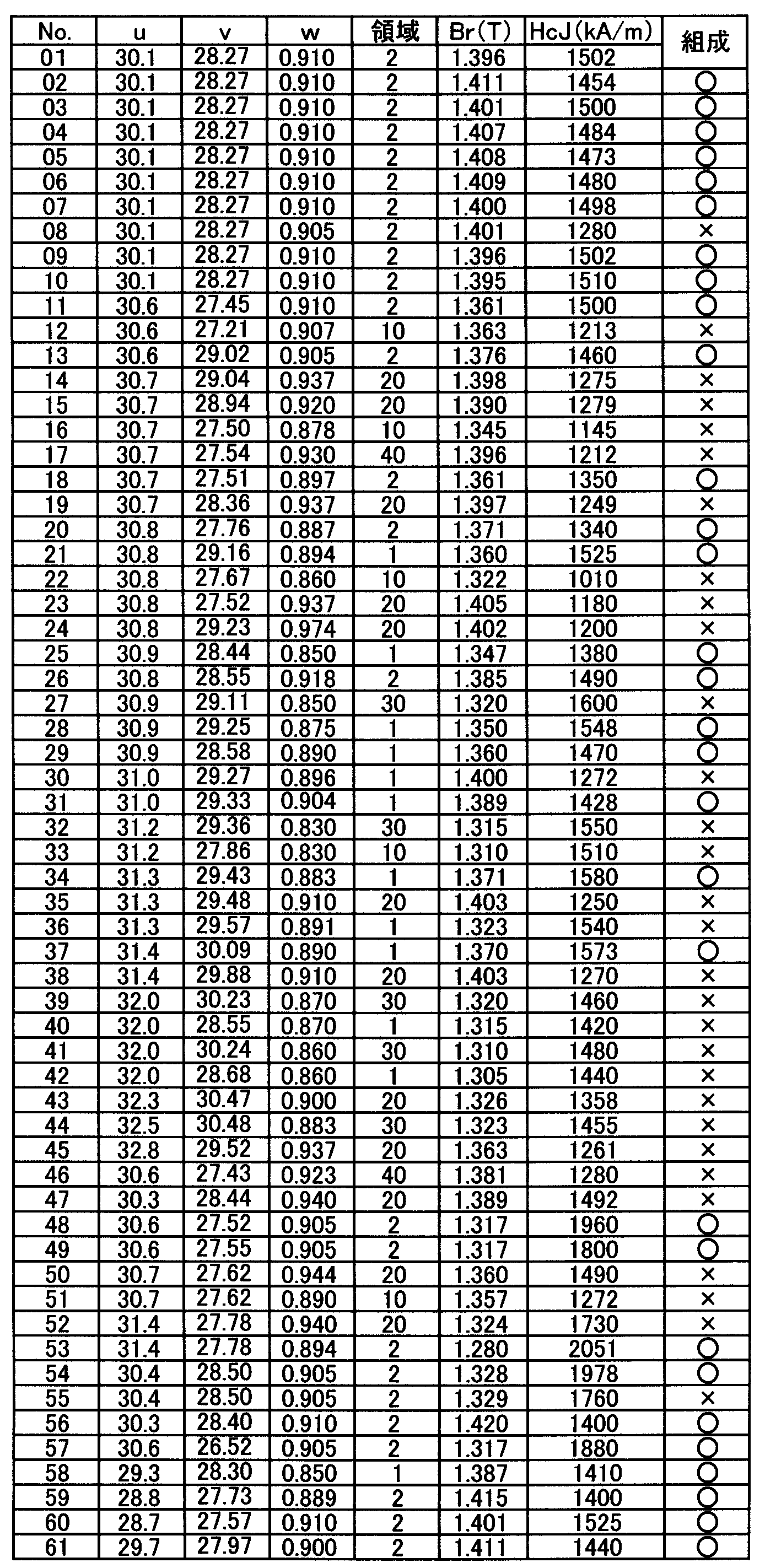
表2におけるuは、表1におけるNd、Pr、Dy、Tbの量を合計した値であり、vは、表1における酸素量(質量%)をα、窒素量(質量%)をβ、炭素量(質量%)をγとしたとき6α+10β+8γをuから差し引いた値である。wは、表1のB量をそのまま転記した。なお、表1におけるNd、Pr、Dy、Tbの量は、それぞれ表記されている数値以下の数値を省略しているため、uおよびvの数値は表1の表記されている数値から求められる値と若干異なっている場合がある。以下に記載される表のuおよびvの数値も同様である。また、表2における領域は、vとwが図1中のどの位置にあるか示したものであり、図1中の1の領域にある場合は1と、図1中の2の領域にある場合は2と記載した。さらに、図1中の1、2の領域以外にある場合はその位置に応じて10、20、30、40のいずれかを記載した。例えばNo.01は、vが28.27質量%であり、wが0.910質量%であるため図1中の2の領域である。そのため2と記載した。また、No.21は、vが29.16質量%であり、wが0.894質量%であるため図1中の1の領域である。そのため1と記載した。さらに、No.47は、vが28.44質量%であり、wが0.940質量%であるため図1中の20の領域である。よって20と記載した。また、表1、表2における組成の欄は、前記態様1又は態様2に示すR-T-B系焼結磁石の組成(以下、単に「態様1又は2に示す組成」と記載する場合がある)範囲内である場合を「○」と、組成範囲外である場合を「×」と記載した。
図4は、図1に態様1又は2に示す組成範囲内である参考例試料と組成範囲外である参考例試料、それぞれのv、wの値をプロットした説明図である。図4から組成範囲内である試料が領域1又は2の範囲内にあり、組成範囲外である試料が領域1及び2の範囲外にあることが容易に理解できる。
図4は、図1に態様1又は2に示す組成範囲内である参考例試料と組成範囲外である参考例試料、それぞれのv、wの値をプロットした説明図である。図4から組成範囲内である試料が領域1又は2の範囲内にあり、組成範囲外である試料が領域1及び2の範囲外にあることが容易に理解できる。
上述したように、態様1又は2に示す組成は、xが0.40質量%以上0.70質量%以下の場合、vとwを以下の割合で含有させる。
50w-18.5≦v≦50w-14 (6)
-12.5w+38.75≦v≦-62.5w+86.125 (7)
好ましくは、
50w-18.5≦v≦50w-16.25 (19)
-12.5w+38.75≦v≦-62.5w+86.125 (7)
当該割合で含有させた場合の前記vとwの範囲が図1中の1と2又は2の領域に相当する。
50w-18.5≦v≦50w-14 (6)
-12.5w+38.75≦v≦-62.5w+86.125 (7)
好ましくは、
50w-18.5≦v≦50w-16.25 (19)
-12.5w+38.75≦v≦-62.5w+86.125 (7)
当該割合で含有させた場合の前記vとwの範囲が図1中の1と2又は2の領域に相当する。
表2に示す様に、原料合金にDy、Tbを含有していない場合、vとwの関係が態様1又は2に示す組成領域(図1中の1と2の領域)に位置し、かつ、0.40≦x(Ga)≦0.70、0.07≦y(Cu)≦0.2、0.05≦z(Al)≦0.5、0≦q(M)≦0.3である参考例試料(試料No.48、49、53、54、57以外で組成が「○」である参考例試料)は、いずれもBr≧1.340T、かつ、HcJ≧1300kA/mの高い磁気特性を有している。これに対し、Ga、Cu、Alの量が態様1又は2に示す組成範囲内であっても、vとwが態様1又は2に示す組成範囲外(図1中の1又は2以外の領域)となっている参考例試料(例えば、試料No.12、16、22、35)及び、vとwが態様1又は2に示す組成範囲内(図1中の1又は2の領域)であってもGa、Cuの量が態様1又は2に示す組成範囲外である参考例試料(例えば、試料No.08、30、36、40、42)は、Br≧1.340T、かつ、HcJ≧1300kA/mの高い磁気特性が得られていない。特に、態様1又は2に示す組成範囲内である試料No.07とGaの含有量が試料No.07と比べて0.17質量%低い以外は同じ組成である試料No.08から明らかなように、vとwが態様1又は2に示す組成範囲内であっても、Gaが態様1又は2に示す組成範囲外であるとHcJが大きく低下している。なお、試料No.08は、Gaが0.20質量%以上0.40質量%未満の場合における態様1又は2に示すGaの組成範囲(-(62.5w+v-81.625)/15+0.5≦x(Ga)≦-(62.5w+v-81.625)/15+0.8)から外れるため、高い磁気特性を得るために最低限必要なR-T-Ga相を生成させることができず、そのため、HcJが大きく低下していると考えられる。
原料合金にDy、Tbを含有する場合はDy、Tbの含有量に応じてBrが低下して、HcJが向上する。この場合、BrはDyやTbを1質量%含有すると0.024T程度減少する。HcJはDyが1質量%含有されると160kA/m程度、Tbが1質量%含有されると240kA/m程度上昇する。
そのため、態様1又は2に示す組成範囲内は、上述したように原料合金にDy、Tbを含有しない場合はBr≧1.340T、かつ、HcJ≧1300kA/mの磁気特性を有しているので、Dy、Tbの含有量に応じてBr(T)≧1.340-0.024[Dy]-0.024[Tb]、かつ、HcJ(kA/m)≧1300+160[Dy]+240[Tb]の磁気特性を有することになる。なお、[Dy][Tb]は、それぞれDy、Tbの含有量(質量%)を示す。
そのため、態様1又は2に示す組成範囲内は、上述したように原料合金にDy、Tbを含有しない場合はBr≧1.340T、かつ、HcJ≧1300kA/mの磁気特性を有しているので、Dy、Tbの含有量に応じてBr(T)≧1.340-0.024[Dy]-0.024[Tb]、かつ、HcJ(kA/m)≧1300+160[Dy]+240[Tb]の磁気特性を有することになる。なお、[Dy][Tb]は、それぞれDy、Tbの含有量(質量%)を示す。
表2に示すように、態様1又は2に示す組成範囲内で原料合金にDy、Tbを含有している参考例試料(試料No.48、49、53、54、57)は、いずれもBr(T)≧1.340-0.024[Dy]-0.024[Tb]、かつ、HcJ(kA/m)≧1300+160[Dy]+240[Tb]の高い磁気特性を有している。これに対し、態様1又は2に示す組成範囲外で原料合金にDy、Tbを含有している参考例試料(試料No.47、50、51、52、55)は、いずれもBr(T)≧1.340-0.024[Dy]-0.024[Tb]、かつ、HcJ(kA/m)≧1300+160[Dy]+240[Tb]の高い磁気特性を有していない。特に、態様1又は2に示す組成範囲内である試料No.54と、Gaの含有量が試料No.54に比べて0.18質量%低い以外は同じ組成である試料No.55とから明らかなように、vとwが態様1又は2に示す組成範囲内であっても、Gaが態様1又は2に示す組成範囲外であるとHcJが大きく低下している。なお、試料No.55は、Gaが0.20質量%以上0.40質量%未満の場合における態様1又は2に示すGaの組成範囲(-(62.5w+v-81.625)/15+0.5≦x(Ga)≦-(62.5w+v-81.625)/15+0.8)から外れるため、高い磁気特性を得るために最低限必要なR-T-Ga相を生成させることができず、そのため、HcJが大きく低下していると考えられる。
さらに、表2に示すように、態様1又は2に示す組成範囲内において領域の1(図1中の1の領域)よりも領域の2(図1中の2の領域)の方が更に高いBr(原料合金にDy、Tbを含有しない場合Br≧1.360T、Dy、Tbを含有する場合、Br≧1.360T-0.024[Dy]-0.024[Tb])を得ることができる。なお、[Dy][Tb]は、それぞれDy、Tbの含有量(質量%)を示す。
<参考例2>
Ndメタル、Prメタル、Dyメタル、フェロボロン合金、電解Co、Alメタル、Cuメタル、Gaメタル、フェロニオブ合金、フェロジルコニウム合金及び電解鉄を用いて(メタルはいずれも純度99%以上)、表3の組成となるように配合し、参考例1と同様の方法により粒径D50が4μmの微粉砕粉(合金粉末)を得た。なお、粉砕時に窒素ガスに大気を混合することにより粉砕時の窒素ガス中の酸素濃度を調節した。大気を混合しない場合の粉砕時の窒素ガス中の酸素濃度は50ppm以下であり、大気を混合することで窒素ガス中の酸素濃度を最大1500ppmまで増加させ、様々な酸素量の微粉砕粉を作製した。なお、粒径D50は、気流分散式によるレーザー回折法で得られた体積基準メジアン径である。また、表3におけるO(酸素量)、N(窒素量)、C(炭素量)は参考例1と同様の方法で測定した。
Ndメタル、Prメタル、Dyメタル、フェロボロン合金、電解Co、Alメタル、Cuメタル、Gaメタル、フェロニオブ合金、フェロジルコニウム合金及び電解鉄を用いて(メタルはいずれも純度99%以上)、表3の組成となるように配合し、参考例1と同様の方法により粒径D50が4μmの微粉砕粉(合金粉末)を得た。なお、粉砕時に窒素ガスに大気を混合することにより粉砕時の窒素ガス中の酸素濃度を調節した。大気を混合しない場合の粉砕時の窒素ガス中の酸素濃度は50ppm以下であり、大気を混合することで窒素ガス中の酸素濃度を最大1500ppmまで増加させ、様々な酸素量の微粉砕粉を作製した。なお、粒径D50は、気流分散式によるレーザー回折法で得られた体積基準メジアン径である。また、表3におけるO(酸素量)、N(窒素量)、C(炭素量)は参考例1と同様の方法で測定した。
前記微粉砕粉に、潤滑剤としてステアリン酸亜鉛を微粉砕粉100質量部に対して0.05質量部添加、混合した後、参考例1と同様の方法で、成形体を作製し、さらに参考例1と同様の方法で焼結、熱処理を行った。熱処理後の焼結磁石に機械加工を施し、参考例1と同様の方法で各試料のBr及びHcJを測定した。測定結果を表4に示す。
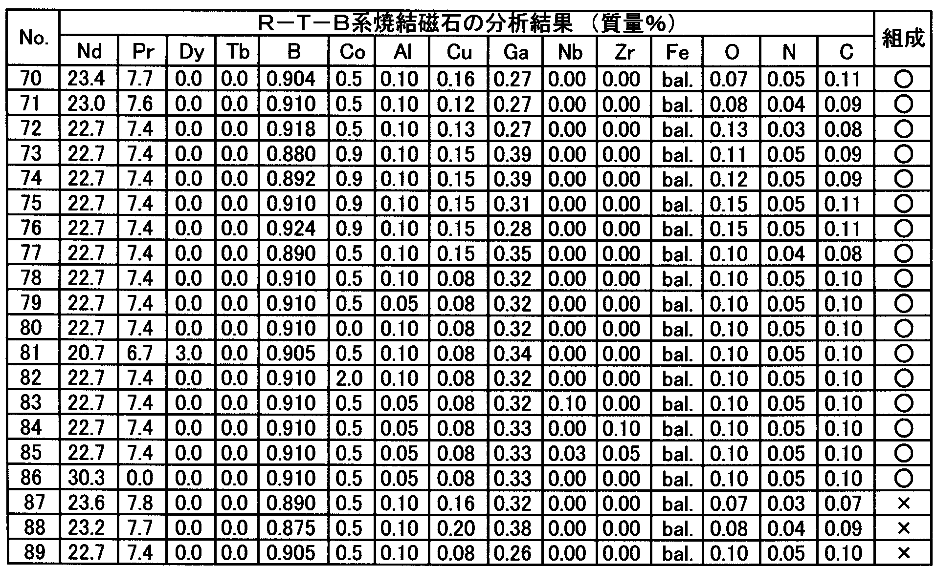

表4におけるuは、表3におけるNd、Pr、Dy、Tbの量(質量%)を合計した値であり、vは、表3における酸素量(質量%)をα、窒素量(質量%)をβ、炭素量(質量%)をγとしたとき6α+10β+8γをuから差し引いた値である。wは、表3のB量をそのまま転記した。表4における領域は、vとwが図2中のどの位置にあるか示したものであり、図2中の3の領域にある場合は3と、図2中の4の領域にある場合は4と記載した。さらに、図2中の3、4の領域以外にある場合は「/」と記載した。また、表3、表4における組成の欄は、態様1又は2に示す組成範囲内である場合を「○」と、組成範囲外である場合を「×」と記載した。
表4に示す様に、原料合金にDy、Tbを含有していない場合、0.20≦x(Ga)<0.40のとき、vとwの関係が態様1又は2に示す組成領域(図2中の3と4の領域)に位置し、かつ、-(62.5w+v-81.625)/15+0.5≦x≦-(62.5w+v-81.625)/15+0.8、0.07≦y(Cu)≦0.2、0.05≦z(Al)≦0.5、0≦q≦0.3である参考例試料(試料No.81以外で組成が「○」である参考例試料)は、いずれもBr≧1.377T、かつ、HcJ≧1403kA/mであり、参考例1の態様1又は2に示す組成範囲内の試料(図1、2における組成が「○」の試料)よりも少ないGaの量(参考例1は、x(Ga)0.40質量%以上)に係らず、参考例1と比較して同等以上の高い磁気特性を有している。これに対し、Ga、Cu、Alの量が態様1又は2に示す組成範囲内であっても、vとwが態様1又は2に示す組成範囲外(図2中の3又は4以外の領域)である試料No.87、88及び、vとwが態様1又は2に示す組成範囲内(図2中の3又は4の領域)であってもGaが態様1又は2に示す組成範囲外である比較例試料No.89は、Br≧1.377T、かつ、HcJ≧1403kA/mの高い磁気特性が得られていない。
<実施例1>
Ndメタル、Prメタル、Dyメタル、フェロボロン合金、電解Co、Alメタル、Cuメタル、Gaメタル、フェロニオブ合金、フェロジルコニウム合金、Tiメタル及び電解鉄を原料として(メタルはいずれも純度99%以上)、表5に示す組成となるように原料を配合・溶解して、主合金粉末の原料合金及び添加合金粉末の原料合金を作製した。主合金粉末の原料合金はストリップキャスト法により鋳造し、厚み0.2~0.5mmのフレーク状の原料合金を得た。また、添加合金粉末の原料合金は、上述したメルトスピニング法により作製した。具体的には、80kPaのアルゴン雰囲気としたチャンバー内にて、オリフィス径0.8mmの石英ノズル内で原料を高周波溶解した後、100kPaのバックプレッシャーを印加して、溶湯をCuロール上へ噴射した。Cuロール周速度は組成に応じて10~40m/sの範囲で行った。得られた原料合金の厚さ方向における寸法を100個測定して平均値を求めた。平均値は組成に応じて0.075~0.084mmの間であった。得られた原料合金(主合金粉末に使用する原料合金および添加合金粉末に使用する原料合金)に対して水素加圧雰囲気で水素脆化させた後、550℃まで真空中で加熱、冷却する脱水素処理を施し、粗粉砕粉を得た。得られた添加合金の粗粉砕粉末と主合金の粗粉砕粉末を表6に示す混合量でV型混合機に投入して混合し、混合合金粉末を得た。得られた混合合金粉末に潤滑剤としてステアリン酸亜鉛を粗粉砕粉100質量部に対して0.04質量部添加、混合した後、ジェットミル装置を用いて、窒素気流中で乾式粉砕し、粒径D50が4μmの微粉砕粉となした混合合金粉末を得た。なお、粉砕時に窒素ガスに大気を混合することにより粉砕時の窒素ガス中の酸素濃度を調節した。大気を混合しない場合の粉砕時の窒素ガス中の酸素濃度は50ppm以下であり、大気を混合することで窒素ガス中の酸素濃度を最大5500ppmまで増加させ、様々な酸素量の微粉砕粉を作製した。なお、粒径D50は、気流分散式によるレーザー回折法で得られた体積基準メジアン径である。また、表7におけるO(酸素量)、N(窒素量)、C(炭素量)は参考例1と同様の方法で測定した。
Ndメタル、Prメタル、Dyメタル、フェロボロン合金、電解Co、Alメタル、Cuメタル、Gaメタル、フェロニオブ合金、フェロジルコニウム合金、Tiメタル及び電解鉄を原料として(メタルはいずれも純度99%以上)、表5に示す組成となるように原料を配合・溶解して、主合金粉末の原料合金及び添加合金粉末の原料合金を作製した。主合金粉末の原料合金はストリップキャスト法により鋳造し、厚み0.2~0.5mmのフレーク状の原料合金を得た。また、添加合金粉末の原料合金は、上述したメルトスピニング法により作製した。具体的には、80kPaのアルゴン雰囲気としたチャンバー内にて、オリフィス径0.8mmの石英ノズル内で原料を高周波溶解した後、100kPaのバックプレッシャーを印加して、溶湯をCuロール上へ噴射した。Cuロール周速度は組成に応じて10~40m/sの範囲で行った。得られた原料合金の厚さ方向における寸法を100個測定して平均値を求めた。平均値は組成に応じて0.075~0.084mmの間であった。得られた原料合金(主合金粉末に使用する原料合金および添加合金粉末に使用する原料合金)に対して水素加圧雰囲気で水素脆化させた後、550℃まで真空中で加熱、冷却する脱水素処理を施し、粗粉砕粉を得た。得られた添加合金の粗粉砕粉末と主合金の粗粉砕粉末を表6に示す混合量でV型混合機に投入して混合し、混合合金粉末を得た。得られた混合合金粉末に潤滑剤としてステアリン酸亜鉛を粗粉砕粉100質量部に対して0.04質量部添加、混合した後、ジェットミル装置を用いて、窒素気流中で乾式粉砕し、粒径D50が4μmの微粉砕粉となした混合合金粉末を得た。なお、粉砕時に窒素ガスに大気を混合することにより粉砕時の窒素ガス中の酸素濃度を調節した。大気を混合しない場合の粉砕時の窒素ガス中の酸素濃度は50ppm以下であり、大気を混合することで窒素ガス中の酸素濃度を最大5500ppmまで増加させ、様々な酸素量の微粉砕粉を作製した。なお、粒径D50は、気流分散式によるレーザー回折法で得られた体積基準メジアン径である。また、表7におけるO(酸素量)、N(窒素量)、C(炭素量)は参考例1と同様の方法で測定した。
添加合金粉末と主合金粉末を混合して得られた微粉砕粉(混合合金粉末)に、潤滑剤としてステアリン酸亜鉛を微粉砕粉100質量部に対して0.05質量部添加、混合した後、参考例1と同様の方法で、成形体を作製し、さらに参考例1と同様の方法で焼結、熱処理を行った。得られたR-T-B系焼結磁石の組成を表7に示す。熱処理後の焼結磁石に機械加工を施し、参考例1と同様の方法で各試料のBr及びHcJを測定した。測定結果を表8に示す。
表7における試料No.100のR-T-B系焼結磁石は、表5のA合金粉末(添加合金粉末)とA-1合金粉末(主合金粉末)を表6に示す混合量で混合した混合合金粉末を用いて作製したものであり、前記添加合金粉末(A合金粉末)と前記主合金粉末(A-1合金粉末)の合計100質量部に対して前記添加合金粉末(A合金粉末)を4質量部含む、前記添加合金粉末と前記主合金粉末との混合合金粉末を用いている。試料No.101~135も同様の方法で記載している。また、表8におけるuは、表7におけるNd、Pr、Dyの量を合計した値であり、vは、表7における酸素量(質量%)をα、窒素量(質量%)をβ、炭素量(質量%)をγとしたとき6α+10β+8γをuから差し引いた値である。wは、表7のB量をそのまま転記した。また、表7における領域は、vとwが図1中のどの位置にあるか示したものであり、図1中の1の領域にある場合は1と、図1中の2の領域にある場合は2と記載した。さらに、図1中の1、2の領域以外にある場合はその位置に応じて10、20、30、40のいずれかを記載した。

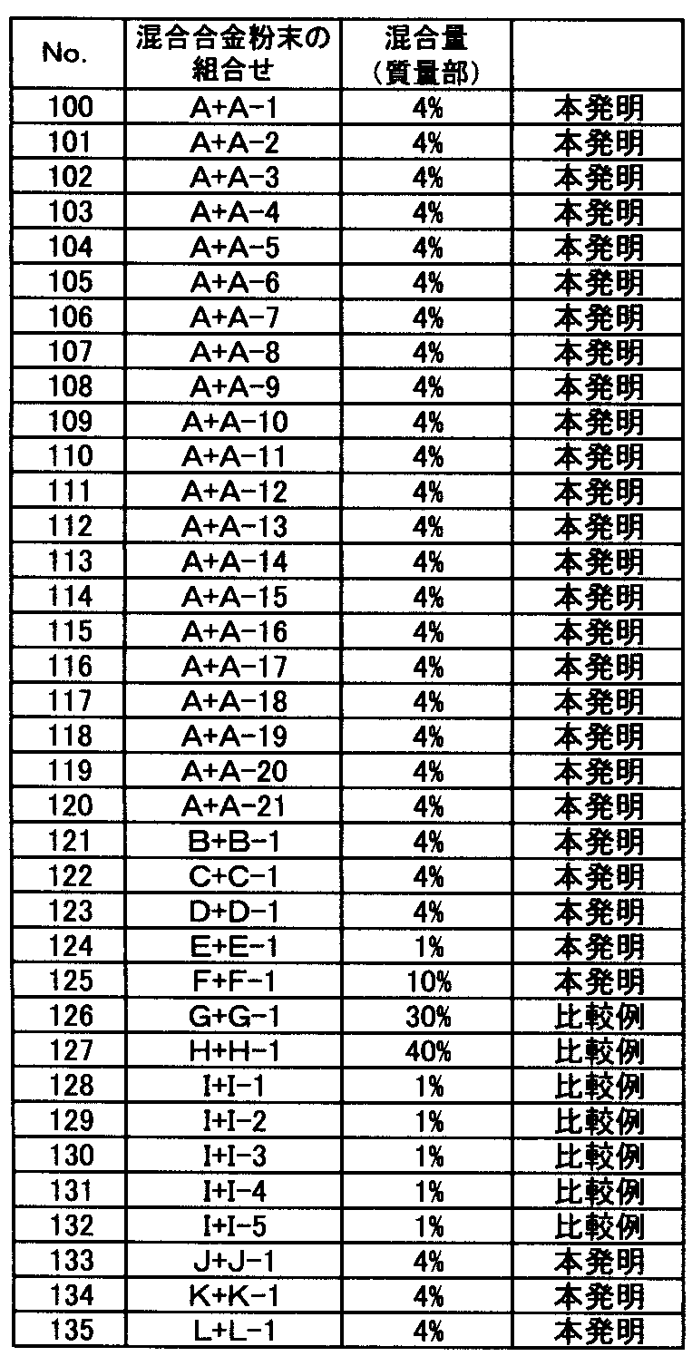
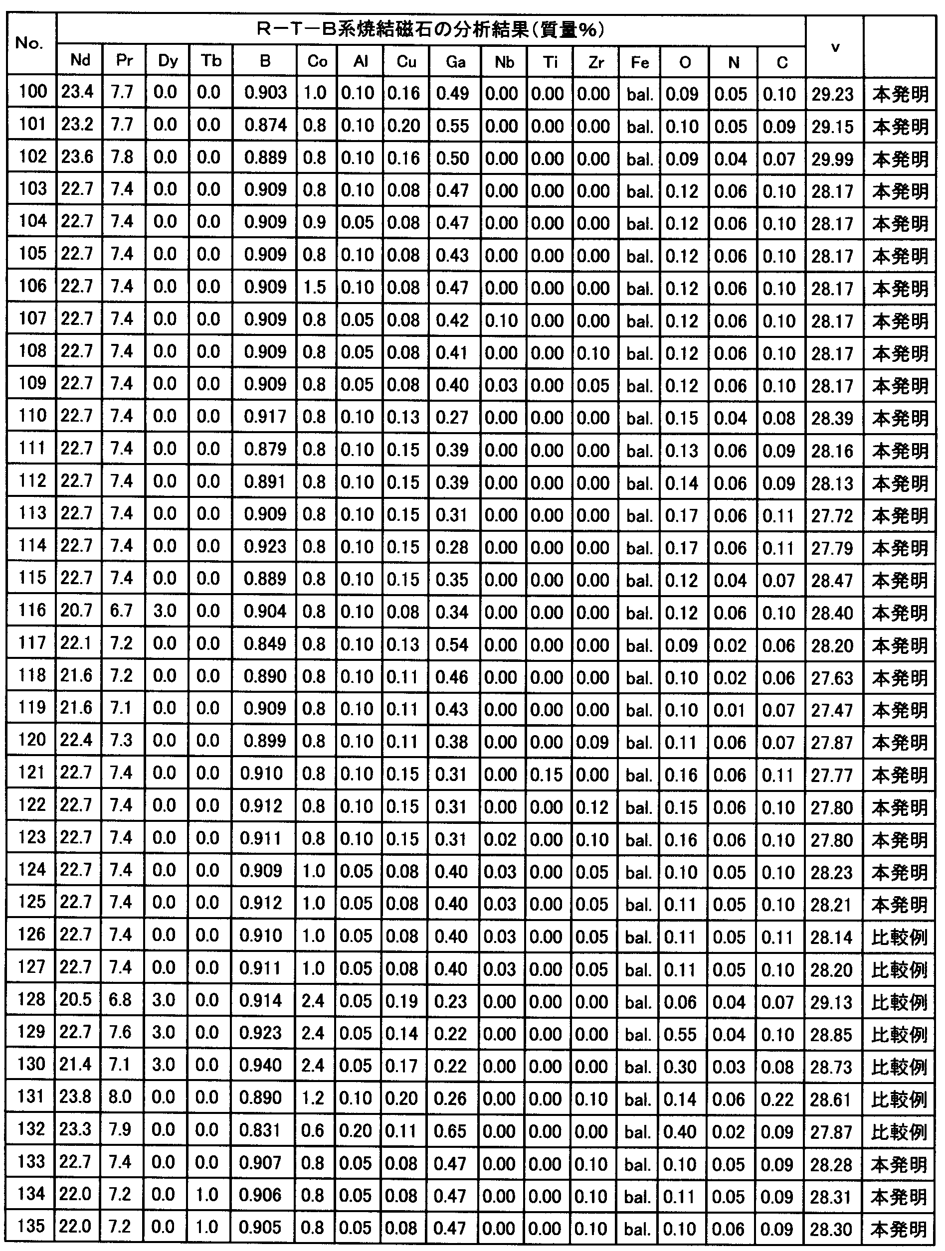
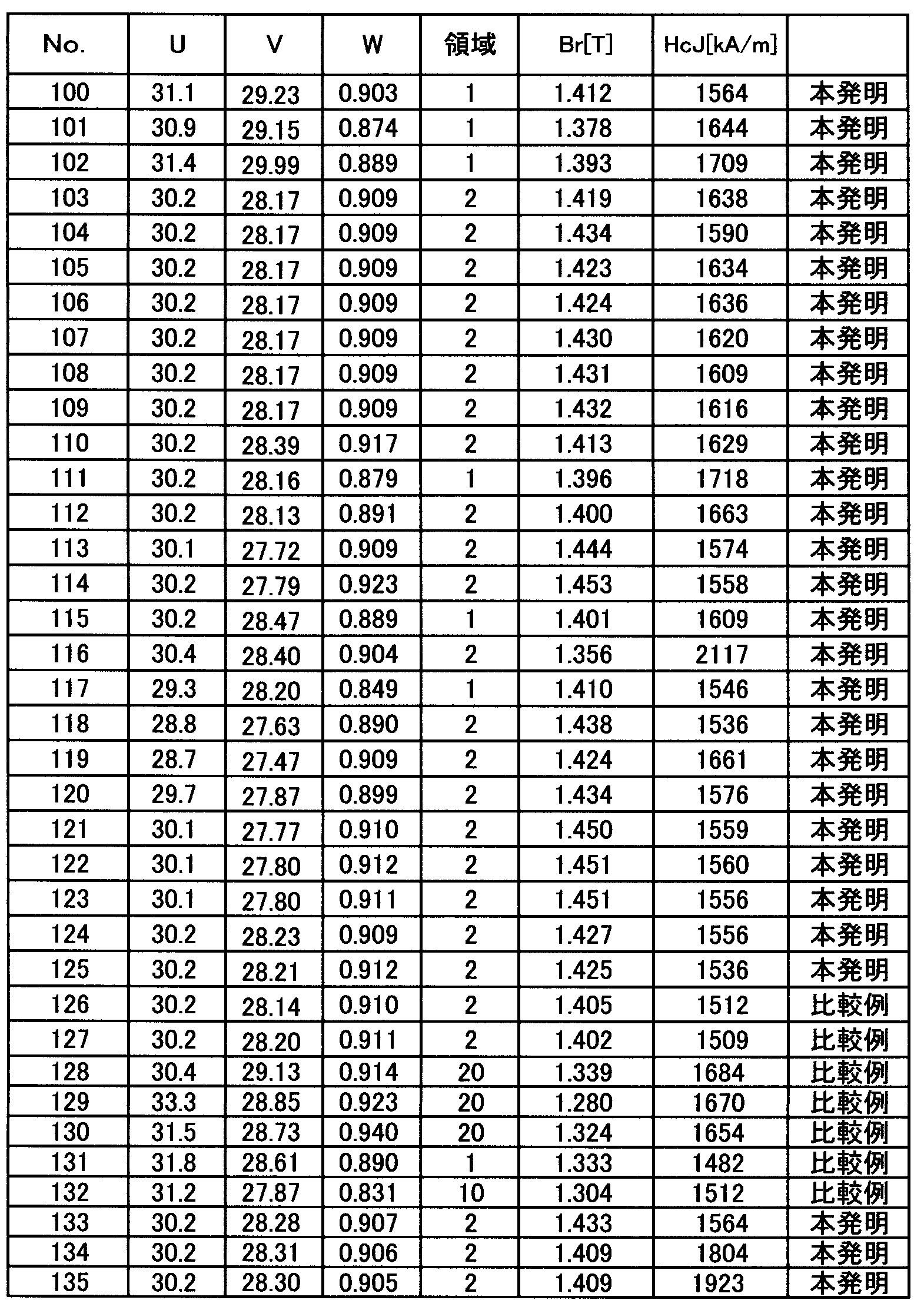
表8に示すように、本発明の製造方法(厚さ0.12mm以下の原料合金を用いて作製した本発明の組成を有する添加合金粉末と、Gaの含有量が0.4質量%以下である主合金粉末を準備し、前記添加合金粉末と前記主合金粉末の合計100質量部に対して前記添加合金粉末を0.5~10質量部含む、前記添加合金粉末と前記主合金粉末との混合合金粉末を用いる)により、態様1又2に示す組成範囲内で作製した試料No.100~125及び試料No.133~135は、原料合金にDy、Tbを含有しない場合(試料No.116、134、135以外の本発明)はBr≧1.378T、かつ、HcJ≧1536kA/mと参考例1、2と比較してさらに高いBrと高いHcJを得ることができる。さらに、原料合金にDy、Tbを含有する場合(試料No.116、134、135)もBr(T)≧1.340-0.024[Dy]-0.024[Tb]、かつ、HcJ(kA/m)≧1300+160[Dy]+240[Tb]の高いBrと高いHcJが得られている。さらに、表8に示すように、本発明において領域の1(図1中の1の領域)よりも領域の2(図1中の2の領域)の方が更に高いBr(原料合金にDy、Tbを含有しない場合Br≧1.400T)を得ることができる。これに対し、態様1又は2に示す組成範囲内であっても本発明の製造方法でない(添加合金粉末と主合金粉末の混合比率が本発明の範囲外)である試料No.126、127や本発明の製造方法であっても態様1又は2に示す組成範囲外である試料No.128~132(試料No.128~130及び132は図1中の領域1、2以外の組成範囲、試料No.131はGaが組成範囲外)は、Br≧1.378T、かつ、HcJ≧1536kA/mの高い磁気特性が得られていない。
<実施例2>
Ndメタル、Prメタル、フェロボロン合金、電解Co、Alメタル、Cuメタル、Gaメタル、及び電解鉄を用いて(メタルはいずれも純度99%以上)、表9に示す組成となるように添加合金粉末及び主合金粉末を配合し、主合金粉末については、それらの原料を溶解してストリップキャスト法により鋳造し、厚み0.3~0.4mmのフレーク状の原料合金を得た。また、添加合金粉末については、実施例1と同じ条件でメルトスピニング法により作製した。得られた原料合金の厚さ方向における寸法をそれぞれ100個測定して平均値を求めた。平均値は組成に応じて0.075~0.082mmの間であった。それぞれ得られた原料合金に対して水素加圧雰囲気で水素脆化させた後、550℃まで真空中で加熱、冷却する脱水素処理を施し、粗粉砕粉を得た。得られた添加合金の粗粉砕粉末と主合金の粗粉砕粉末を表10に示す混合量でV型混合機に投入して混合し、混合合金粉末を得た。得られた混合合金粉末に潤滑剤としてステアリン酸亜鉛を粗粉砕粉100質量部に対して0.04質量部添加、混合した後、ジェットミル装置を用いて、窒素気流中で乾式粉砕し、粒径D50が4μmの微粉砕粉となした混合合金粉末を得た。なお、粉砕時に窒素ガスに大気を混合することにより粉砕時の窒素ガス中の酸素濃度を調節した。大気を混合しない場合の粉砕時の窒素ガス中の酸素濃度は50ppm以下であり、大気を混合することで窒素ガス中の酸素濃度を最大1600ppmまで増加させ、様々な酸素量の微粉砕粉を作製した。なお、粒径D50は、気流分散式によるレーザー回折法で得られた体積基準メジアン径である。また、表11におけるO(酸素量)、N(窒素量)、C(炭素量)は参考例1と同様の方法で測定した。
Ndメタル、Prメタル、フェロボロン合金、電解Co、Alメタル、Cuメタル、Gaメタル、及び電解鉄を用いて(メタルはいずれも純度99%以上)、表9に示す組成となるように添加合金粉末及び主合金粉末を配合し、主合金粉末については、それらの原料を溶解してストリップキャスト法により鋳造し、厚み0.3~0.4mmのフレーク状の原料合金を得た。また、添加合金粉末については、実施例1と同じ条件でメルトスピニング法により作製した。得られた原料合金の厚さ方向における寸法をそれぞれ100個測定して平均値を求めた。平均値は組成に応じて0.075~0.082mmの間であった。それぞれ得られた原料合金に対して水素加圧雰囲気で水素脆化させた後、550℃まで真空中で加熱、冷却する脱水素処理を施し、粗粉砕粉を得た。得られた添加合金の粗粉砕粉末と主合金の粗粉砕粉末を表10に示す混合量でV型混合機に投入して混合し、混合合金粉末を得た。得られた混合合金粉末に潤滑剤としてステアリン酸亜鉛を粗粉砕粉100質量部に対して0.04質量部添加、混合した後、ジェットミル装置を用いて、窒素気流中で乾式粉砕し、粒径D50が4μmの微粉砕粉となした混合合金粉末を得た。なお、粉砕時に窒素ガスに大気を混合することにより粉砕時の窒素ガス中の酸素濃度を調節した。大気を混合しない場合の粉砕時の窒素ガス中の酸素濃度は50ppm以下であり、大気を混合することで窒素ガス中の酸素濃度を最大1600ppmまで増加させ、様々な酸素量の微粉砕粉を作製した。なお、粒径D50は、気流分散式によるレーザー回折法で得られた体積基準メジアン径である。また、表11におけるO(酸素量)、N(窒素量)、C(炭素量)は参考例1と同様の方法で測定した。
添加合金粉末と主合金粉末を混合して得られた微粉砕粉(混合合金粉末)に、潤滑剤としてステアリン酸亜鉛を微粉砕粉100質量部に対して0.05質量部添加、混合した後、参考例1と同様の方法で、成形体を作製し、さらに参考例1と同様の方法で焼結、熱処理を行った。得られたR-T-B系焼結磁石の組成を表11に示す。熱処理後の焼結磁石に機械加工を施し、参考例1と同様の方法で各試料のBr及びHcJを測定した。測定結果を表12に示す。
表11における試料No.140のR-T-B系焼結磁石は、表9のM合金粉末(添加合金粉末)とM-1合金粉末(主合金粉末)とM-2合金粉末(主合金粉末)を表10に示す混合量で混合した混合合金粉末を用いて作製したものであり、混合量は、前記添加合金粉末(M合金粉末)と前記主合金粉末(M-1およびM-2合金粉末)の合計100質量部に対して添加合金粉末(M):4質量部、主合金粉末(M-1)48質量部、主合金粉末(M-2)48質量部である。試料No.141、142も同様の方法で記載している。また、表12におけるuは、表11におけるNd、Pr、Dyの量を合計した値であり、vは、表11における酸素量(質量%)をα、窒素量(質量%)をβ、炭素量(質量%)をγとしたとき6α+10β+8γをuから差し引いた値である。wは、表11のB量をそのまま転記した。また、表12における領域は、vとwが図1中のどの位置にあるか示したものであり、図1中の1の領域にある場合は1と、図1中の2の領域にある場合は2と記載した。なお、表9に示す添加合金粉末及び主合金粉末の組成、表10に示す添加合金粉末の混合量および表11に示すR-T-B系焼結磁石の組成は、全て本発明の範囲内である。

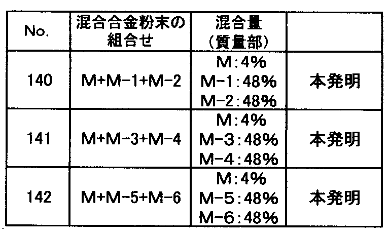

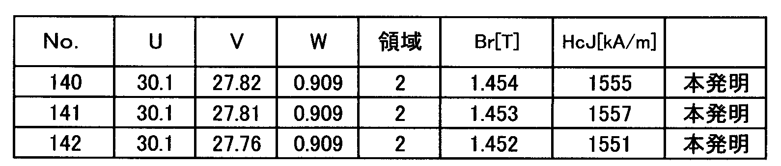
表12に示すように、一種の添加合金粉末と二種の主合金粉末を混合してR-T-B系焼結磁石を作製した試料No.140~142は、いずれもBr≧1.378T、かつ、HcJ≧1536kA/mと参考例1、2と比較してさらに高いBrと高いHcJを得ることができる。
<実施例3>
Ndメタル、Prメタル、フェロボロン合金、電解Co、Alメタル、Cuメタル、Gaメタル、及び電解鉄を用いて(メタルはいずれも純度99%以上)、表13に示す組成となるように添加合金粉末及び主合金粉末を配合し、主合金粉末については、それらの原料を溶解してストリップキャスト法により鋳造し、厚み0.3~0.4mmのフレーク状の原料合金を得た。また、添加合金粉末については、メルトスピニング法により原料合金の厚さ(原料合金の厚さ方向における寸法を100個測定した平均値)を二種類(表13の合金粉末Nは厚さ0.1mmの原料合金、表13の合金粉末NAは厚さ0.02mmの原料合金)作製した。それぞれ得られた原料合金に対して水素加圧雰囲気で水素脆化させた後、550℃まで真空中で加熱、冷却する脱水素処理を施し、粗粉砕粉を得た。得られた添加合金の粗粉砕粉末と主合金の粗粉砕粉末を表14に示す混合量でV型混合機に投入して混合し、混合合金粉末を得た。得られた混合合金粉末に潤滑剤としてステアリン酸亜鉛を粗粉砕粉100質量部に対して0.04質量部添加、混合した後、ジェットミル装置を用いて、窒素気流中で乾式粉砕し、粒径D50が4μmの微粉砕粉となした混合合金粉末を得た。なお、粉砕時に窒素ガスに大気を混合することにより粉砕時の窒素ガス中の酸素濃度を調節した。大気を混合しない場合の粉砕時の窒素ガス中の酸素濃度は50ppm以下であり、大気を混合することで窒素ガス中の酸素濃度を最大1100ppmまで増加させ、様々な酸素量の微粉砕粉を作製した。なお、粒径D50は、気流分散式によるレーザー回折法で得られた体積基準メジアン径である。また、表15におけるO(酸素量)、N(窒素量)、C(炭素量)は参考例1と同様の方法で測定した。
Ndメタル、Prメタル、フェロボロン合金、電解Co、Alメタル、Cuメタル、Gaメタル、及び電解鉄を用いて(メタルはいずれも純度99%以上)、表13に示す組成となるように添加合金粉末及び主合金粉末を配合し、主合金粉末については、それらの原料を溶解してストリップキャスト法により鋳造し、厚み0.3~0.4mmのフレーク状の原料合金を得た。また、添加合金粉末については、メルトスピニング法により原料合金の厚さ(原料合金の厚さ方向における寸法を100個測定した平均値)を二種類(表13の合金粉末Nは厚さ0.1mmの原料合金、表13の合金粉末NAは厚さ0.02mmの原料合金)作製した。それぞれ得られた原料合金に対して水素加圧雰囲気で水素脆化させた後、550℃まで真空中で加熱、冷却する脱水素処理を施し、粗粉砕粉を得た。得られた添加合金の粗粉砕粉末と主合金の粗粉砕粉末を表14に示す混合量でV型混合機に投入して混合し、混合合金粉末を得た。得られた混合合金粉末に潤滑剤としてステアリン酸亜鉛を粗粉砕粉100質量部に対して0.04質量部添加、混合した後、ジェットミル装置を用いて、窒素気流中で乾式粉砕し、粒径D50が4μmの微粉砕粉となした混合合金粉末を得た。なお、粉砕時に窒素ガスに大気を混合することにより粉砕時の窒素ガス中の酸素濃度を調節した。大気を混合しない場合の粉砕時の窒素ガス中の酸素濃度は50ppm以下であり、大気を混合することで窒素ガス中の酸素濃度を最大1100ppmまで増加させ、様々な酸素量の微粉砕粉を作製した。なお、粒径D50は、気流分散式によるレーザー回折法で得られた体積基準メジアン径である。また、表15におけるO(酸素量)、N(窒素量)、C(炭素量)は参考例1と同様の方法で測定した。
添加合金粉末と主合金粉末を混合して得られた微粉砕粉(混合合金粉末)に、潤滑剤としてステアリン酸亜鉛を微粉砕粉100質量部に対して0.05質量部添加、混合した後、参考例1と同様の方法で、成形体を作製し、さらに参考例1と同様の方法で焼結、熱処理を行った。得られたR-T-B系焼結磁石の組成を表15に示す。熱処理後の焼結磁石に機械加工を施し、参考例1と同様の方法で各試料のBr及びHcJを測定した。測定結果を表16に示す。
表15における試料No.145のR-T-B系焼結磁石は、表13のN合金粉末(添加合金粉末)とN-1合金粉末(主合金粉末)とN-2合金粉末(主合金粉末)を表14に示す混合量で混合した混合合金粉末を用いて作製したものであり、混合量は、前記添加合金粉末(N合金粉末)と前記主合金粉末(N-1およびN-2合金粉末の合計100質量部に対して添加合金粉末(N):4質量部、主合金粉末(N-1)48質量部、主合金粉末(N-2)48質量部である。試料No.147、148も同様の方法で記載している。また、表16におけるuは、表15におけるNd、Pr、Dyの量を合計した値であり、vは、表15における酸素量(質量%)をα、窒素量(質量%)をβ、炭素量(質量%)をγとしたとき6α+10β+8γをuから差し引いた値である。wは、表15のB量をそのまま転記した。また、表16における領域は、vとwが図1中のどの位置にあるか示したものであり、図1中の1の領域にある場合は1と、図1中の2の領域にある場合は2と記載した。なお、表13に示す添加合金粉末及び主合金粉末の組成、表14に示す添加合金粉末の混合量および表15に示すR-T-B系焼結磁石の組成は、全て本発明の範囲内である。


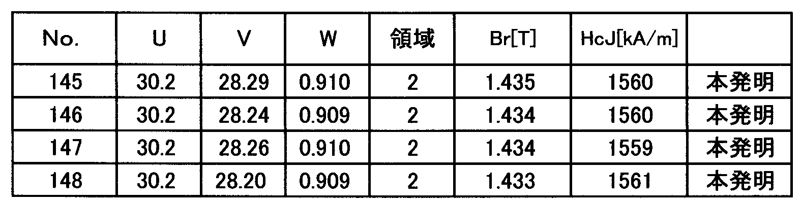
表16に示すように、一種の添加合金粉末と二種の主合金粉末を混合してR-T-B系焼結磁石を作製した試料No.145~148は、いずれもBr≧1.378T、かつ、HcJ≧1536kA/mと参考例1、2と比較してさらに高いBrと高いHcJを得ることができる。
本発明によるR-T-B系焼結磁石は、電気自動車用モータや産業機器用モータなどに好適に利用することができる。
Claims (3)
- 下記式(1)によって表わされ、
uRwBxGayCuzAlqM(100-u-w-x-y-z-q)T (1)
(Rは希土類元素のうち少なくとも一種でありNdを必ず含む、TはFeでありFeの10%以下をCoで置換でき、MはNb、Zr、Tiのうち少なくとも一種であり、u、w、x、y、z、q及び100-u-w-x-y-z-qは質量%を示す。)
下記式(2)~(5)を満足し、
0.20≦x≦0.70 (2)
0.07≦y≦0.2 (3)
0.05≦z≦0.5 (4)
0≦q≦0.3 (5)
R-T-B系焼結磁石の酸素量(質量%)をα、窒素量(質量%)をβ、炭素量(質量%)をγとしたとき、v=u-(6α+10β+8γ)であって、
0.40≦x≦0.70のとき、v、wが、下記式(6)及び(7)を満足し、
50w-18.5≦v≦50w-14 (6)
-12.5w+38.75≦v≦-62.5w+86.125 (7)
0.20≦x<0.40のとき、v、wが、下記式(8)及び(9)を満足し、xが、下記式(10)を満足することを特徴とするR-T-B系焼結磁石の製造方法であって、
50w-18.5≦v≦50w-15.5 (8)
-12.5w+39.125≦v≦-62.5w+86.125 (9)
-(62.5w+v-81.625)/15+0.5≦x≦-(62.5w+v-81.625)/15+0.8 (10)
一種以上の添加合金粉末と一種以上の主合金粉末とを準備する工程と、
前記添加合金粉末と前記主合金粉末の合計100質量部に対して前記添加合金粉末を0.5~10質量部含む、前記添加合金粉末と前記主合金粉末との混合合金粉末を得る工程と、
前記混合合金粉末を成形し成形体を得る成形工程と、
前記成形体を焼結し焼結体を得る焼結工程と、
前記焼結体に熱処理を施す熱処理工程と、
を含み、
前記一種以上の主合金粉末は、Ga含有量が0.4質量%以下であり、
前記一種以上の添加合金粉末は、それぞれ、下記式(11)により表され、下記式(12)~(17)を満足する組成を有し、
aRbBcGadCueAlfM(100-a-b-c-d-e-f)T (11)
(Rは希土類元素のうち少なくとも一種でありNdを必ず含む、TはFeでありFeの10%以下をCoで置換でき、MはNb、Zr、Tiのうち少なくとも一種であり、a、b、c、d、e、f及び100-a-b-c-d-e-fは質量%を示す。)
32≦a≦66 (12)
0.3≦b≦0.9 (13)
0.7≦c≦12 (14)
0≦d≦4 (15)
0≦e≦10 (16)
0≦f≦10 (17)
前記一種以上の添加合金粉末は、厚さ0.12mm以下の原料合金を用いて作製したものであることを特徴とする、
R-T-B系焼結磁石の製造方法。 - 0.40≦x≦0.70のとき、v、wが、下記式(19)及び(7)を満足し、
50w-18.5≦v≦50w-16.25 (19)
-12.5w+38.75≦v≦-62.5w+86.125 (7)
0.20≦x<0.40のとき、v、wが、下記式(20)及び(9)を満足し、xが、下記式(10)を満足することを特徴とする請求項1に記載のR-T-B系焼結磁石の製造方法。
50w-18.5≦v≦50w-17.0 (20)
-12.5w+39.125≦v≦-62.5w+86.125 (9)
-(62.5w+v-81.625)/15+0.5≦x≦-(62.5w+v-81.625)/15+0.8 (10) - R-T-B系焼結磁石の酸素量が0.15質量%以下である、請求項1又は2に記載のR-T-B系焼結磁石の製造方法。
Priority Applications (1)
| Application Number | Priority Date | Filing Date | Title |
|---|---|---|---|
| JP2017500674A JP6642838B2 (ja) | 2015-02-17 | 2016-02-16 | R−t−b系焼結磁石の製造方法 |
Applications Claiming Priority (2)
| Application Number | Priority Date | Filing Date | Title |
|---|---|---|---|
| JP2015-028435 | 2015-02-17 | ||
| JP2015028435 | 2015-02-17 |
Publications (1)
| Publication Number | Publication Date |
|---|---|
| WO2016133067A1 true WO2016133067A1 (ja) | 2016-08-25 |
Family
ID=56689001
Family Applications (1)
| Application Number | Title | Priority Date | Filing Date |
|---|---|---|---|
| PCT/JP2016/054386 Ceased WO2016133067A1 (ja) | 2015-02-17 | 2016-02-16 | R-t-b系焼結磁石の製造方法 |
Country Status (2)
| Country | Link |
|---|---|
| JP (1) | JP6642838B2 (ja) |
| WO (1) | WO2016133067A1 (ja) |
Cited By (13)
| Publication number | Priority date | Publication date | Assignee | Title |
|---|---|---|---|---|
| JP2016192542A (ja) * | 2015-03-30 | 2016-11-10 | 日立金属株式会社 | R−t−b系焼結磁石 |
| CN110537235A (zh) * | 2018-03-23 | 2019-12-03 | 日立金属株式会社 | R-t-b系烧结磁体的制造方法 |
| CN111696777A (zh) * | 2019-03-15 | 2020-09-22 | 日立金属株式会社 | R-t-b系烧结磁体的制造方法 |
| JP2020155763A (ja) * | 2019-03-15 | 2020-09-24 | 日立金属株式会社 | R−t−b系焼結磁石の製造方法 |
| WO2021169901A1 (zh) * | 2020-02-29 | 2021-09-02 | 厦门钨业股份有限公司 | 一种r-t-b系永磁材料及其制备方法和应用 |
| CN113451032A (zh) * | 2020-03-26 | 2021-09-28 | 日立金属株式会社 | R-t-b系烧结磁体的制造方法 |
| JP2022537003A (ja) * | 2019-09-03 | 2022-08-23 | フージャン チャンティン ゴールデン ドラゴン レア-アース カンパニー リミテッド | 希土類永久磁石材料、原料組成物、製造方法、応用、モーター |
| EP4098383A1 (en) * | 2021-05-31 | 2022-12-07 | Baotou Jinshan Magnetic Material Co. Ltd | Neodymium-iron-boron permanent magnet and preparation method and use thereof |
| JP2023510636A (ja) * | 2020-05-29 | 2023-03-14 | フージャン チャンティン ゴールデン ドラゴン レア-アース カンパニー リミテッド | ネオジム鉄ホウ素永久磁石材料、その原料組成物、その製造方法 |
| JP7379362B2 (ja) | 2018-06-19 | 2023-11-14 | 福建省長汀金龍希土有限公司 | 低B含有R-Fe-B系焼結磁石及び製造方法 |
| JP2023177262A (ja) * | 2022-05-31 | 2023-12-13 | 煙台東星磁性材料株式有限公司 | 希土類磁性体及びその製造方法 |
| JP2023177261A (ja) * | 2022-05-31 | 2023-12-13 | 煙台東星磁性材料株式有限公司 | 希土類磁性体及びその製造方法 |
| JP2024522323A (ja) * | 2021-06-10 | 2024-06-18 | ガンジョウ ディーエムイージーシー レア アース マグネット カンパニー リミテッド | ネオジム鉄ホウ素磁石及びその製造方法 |
Families Citing this family (1)
| Publication number | Priority date | Publication date | Assignee | Title |
|---|---|---|---|---|
| JP7059995B2 (ja) * | 2019-03-25 | 2022-04-26 | 日立金属株式会社 | R-t-b系焼結磁石 |
Citations (3)
| Publication number | Priority date | Publication date | Assignee | Title |
|---|---|---|---|---|
| JPH07130522A (ja) * | 1993-11-08 | 1995-05-19 | Tdk Corp | 永久磁石の製造方法 |
| WO2014157448A1 (ja) * | 2013-03-29 | 2014-10-02 | 日立金属株式会社 | R-t-b系焼結磁石 |
| WO2015022946A1 (ja) * | 2013-08-12 | 2015-02-19 | 日立金属株式会社 | R-t-b系焼結磁石およびr-t-b系焼結磁石の製造方法 |
Family Cites Families (4)
| Publication number | Priority date | Publication date | Assignee | Title |
|---|---|---|---|---|
| JP2002038245A (ja) * | 2000-07-27 | 2002-02-06 | Hitachi Metals Ltd | 希土類永久磁石用合金粉末および希土類永久磁石の製造方法 |
| JP5572673B2 (ja) * | 2011-07-08 | 2014-08-13 | 昭和電工株式会社 | R−t−b系希土類焼結磁石用合金、r−t−b系希土類焼結磁石用合金の製造方法、r−t−b系希土類焼結磁石用合金材料、r−t−b系希土類焼結磁石、r−t−b系希土類焼結磁石の製造方法およびモーター |
| JP6044866B2 (ja) * | 2011-09-29 | 2016-12-14 | 日立金属株式会社 | R−t−b系焼結磁石の製造方法 |
| CN105453193B (zh) * | 2013-08-09 | 2018-01-12 | Tdk株式会社 | R‑t‑b系烧结磁铁以及电机 |
-
2016
- 2016-02-16 WO PCT/JP2016/054386 patent/WO2016133067A1/ja not_active Ceased
- 2016-02-16 JP JP2017500674A patent/JP6642838B2/ja active Active
Patent Citations (3)
| Publication number | Priority date | Publication date | Assignee | Title |
|---|---|---|---|---|
| JPH07130522A (ja) * | 1993-11-08 | 1995-05-19 | Tdk Corp | 永久磁石の製造方法 |
| WO2014157448A1 (ja) * | 2013-03-29 | 2014-10-02 | 日立金属株式会社 | R-t-b系焼結磁石 |
| WO2015022946A1 (ja) * | 2013-08-12 | 2015-02-19 | 日立金属株式会社 | R-t-b系焼結磁石およびr-t-b系焼結磁石の製造方法 |
Cited By (21)
| Publication number | Priority date | Publication date | Assignee | Title |
|---|---|---|---|---|
| JP2016192542A (ja) * | 2015-03-30 | 2016-11-10 | 日立金属株式会社 | R−t−b系焼結磁石 |
| CN110537235B (zh) * | 2018-03-23 | 2023-08-18 | 株式会社博迈立铖 | R-t-b系烧结磁体的制造方法 |
| CN110537235A (zh) * | 2018-03-23 | 2019-12-03 | 日立金属株式会社 | R-t-b系烧结磁体的制造方法 |
| JP7379362B2 (ja) | 2018-06-19 | 2023-11-14 | 福建省長汀金龍希土有限公司 | 低B含有R-Fe-B系焼結磁石及び製造方法 |
| CN111696777A (zh) * | 2019-03-15 | 2020-09-22 | 日立金属株式会社 | R-t-b系烧结磁体的制造方法 |
| JP2020155763A (ja) * | 2019-03-15 | 2020-09-24 | 日立金属株式会社 | R−t−b系焼結磁石の製造方法 |
| JP2022537003A (ja) * | 2019-09-03 | 2022-08-23 | フージャン チャンティン ゴールデン ドラゴン レア-アース カンパニー リミテッド | 希土類永久磁石材料、原料組成物、製造方法、応用、モーター |
| JP7220300B2 (ja) | 2019-09-03 | 2023-02-09 | フージャン チャンティン ゴールデン ドラゴン レア-アース カンパニー リミテッド | 希土類永久磁石材料、原料組成物、製造方法、応用、モーター |
| WO2021169901A1 (zh) * | 2020-02-29 | 2021-09-02 | 厦门钨业股份有限公司 | 一种r-t-b系永磁材料及其制备方法和应用 |
| CN113451032A (zh) * | 2020-03-26 | 2021-09-28 | 日立金属株式会社 | R-t-b系烧结磁体的制造方法 |
| JP2021155795A (ja) * | 2020-03-26 | 2021-10-07 | 日立金属株式会社 | R−t−b系焼結磁石の製造方法 |
| JP7600531B2 (ja) | 2020-03-26 | 2024-12-17 | 株式会社プロテリアル | R-t-b系焼結磁石の製造方法 |
| JP2023510636A (ja) * | 2020-05-29 | 2023-03-14 | フージャン チャンティン ゴールデン ドラゴン レア-アース カンパニー リミテッド | ネオジム鉄ホウ素永久磁石材料、その原料組成物、その製造方法 |
| JP7282274B2 (ja) | 2020-05-29 | 2023-05-26 | フージャン チャンティン ゴールデン ドラゴン レア-アース カンパニー リミテッド | ネオジム鉄ホウ素永久磁石材料、その原料組成物、その製造方法 |
| EP4098383A1 (en) * | 2021-05-31 | 2022-12-07 | Baotou Jinshan Magnetic Material Co. Ltd | Neodymium-iron-boron permanent magnet and preparation method and use thereof |
| JP2024522323A (ja) * | 2021-06-10 | 2024-06-18 | ガンジョウ ディーエムイージーシー レア アース マグネット カンパニー リミテッド | ネオジム鉄ホウ素磁石及びその製造方法 |
| JP7879050B2 (ja) | 2021-06-10 | 2026-06-23 | ガンジョウ ディーエムイージーシー レア アース マグネット カンパニー リミテッド | ネオジム鉄ホウ素磁石及びその製造方法 |
| JP2023177262A (ja) * | 2022-05-31 | 2023-12-13 | 煙台東星磁性材料株式有限公司 | 希土類磁性体及びその製造方法 |
| JP2023177261A (ja) * | 2022-05-31 | 2023-12-13 | 煙台東星磁性材料株式有限公司 | 希土類磁性体及びその製造方法 |
| JP7542293B2 (ja) | 2022-05-31 | 2024-08-30 | 煙台東星磁性材料株式有限公司 | 希土類磁性体及びその製造方法 |
| JP7556668B2 (ja) | 2022-05-31 | 2024-09-26 | 煙台東星磁性材料株式有限公司 | 希土類磁性体の製造方法 |
Also Published As
| Publication number | Publication date |
|---|---|
| JP6642838B2 (ja) | 2020-02-12 |
| JPWO2016133067A1 (ja) | 2017-11-30 |
Similar Documents
| Publication | Publication Date | Title |
|---|---|---|
| JP6642838B2 (ja) | R−t−b系焼結磁石の製造方法 | |
| JP6406255B2 (ja) | R−t−b系焼結磁石およびr−t−b系焼結磁石の製造方法 | |
| JP6288095B2 (ja) | R−t−b系焼結磁石の製造方法 | |
| CN107710351B (zh) | R-t-b系烧结磁体及其制造方法 | |
| JP6432718B1 (ja) | R−t−b系焼結磁石の製造方法 | |
| JP6443757B2 (ja) | R−t−b系焼結磁石の製造方法 | |
| JPWO2016043039A1 (ja) | R−t−b系焼結磁石の製造方法 | |
| JPWO2017159576A1 (ja) | R−t−b系焼結磁石の製造方法 | |
| JP6541038B2 (ja) | R−t−b系焼結磁石 | |
| CN106024235B (zh) | R-t-b系烧结磁体 | |
| JP7021577B2 (ja) | R-t-b系焼結磁石の製造方法 | |
| JP7155813B2 (ja) | R-t-b系焼結磁石の製造方法 | |
| JP7021578B2 (ja) | R-t-b系焼結磁石の製造方法 | |
| JP6702215B2 (ja) | R−t−b系焼結磁石 | |
| JP6474043B2 (ja) | R−t−b系焼結磁石 | |
| JP6760160B2 (ja) | R−t−b系焼結磁石の製造方法 | |
| JP6623998B2 (ja) | R−t−b系焼結磁石の製造方法 | |
| CN111755189B (zh) | R-t-b系烧结磁体的制造方法 | |
| JP6229938B2 (ja) | R−t−b系焼結磁石 | |
| JP7548688B2 (ja) | R-t-b系焼結磁石 | |
| JP6627555B2 (ja) | R−t−b系焼結磁石 | |
| JP2020161787A (ja) | R−t−b系焼結磁石の製造方法 | |
| CN111696777A (zh) | R-t-b系烧结磁体的制造方法 | |
| CN111724985A (zh) | R-t-b系烧结磁体的制造方法 | |
| JP2020155763A (ja) | R−t−b系焼結磁石の製造方法 |
Legal Events
| Date | Code | Title | Description |
|---|---|---|---|
| 121 | Ep: the epo has been informed by wipo that ep was designated in this application |
Ref document number: 16752453 Country of ref document: EP Kind code of ref document: A1 |
|
| ENP | Entry into the national phase |
Ref document number: 2017500674 Country of ref document: JP Kind code of ref document: A |
|
| NENP | Non-entry into the national phase |
Ref country code: DE |
|
| 122 | Ep: pct application non-entry in european phase |
Ref document number: 16752453 Country of ref document: EP Kind code of ref document: A1 |