WO2016121427A1 - カメラ用フィルター枠およびカメラ用フィルターユニット - Google Patents
カメラ用フィルター枠およびカメラ用フィルターユニット Download PDFInfo
- Publication number
- WO2016121427A1 WO2016121427A1 PCT/JP2016/050207 JP2016050207W WO2016121427A1 WO 2016121427 A1 WO2016121427 A1 WO 2016121427A1 JP 2016050207 W JP2016050207 W JP 2016050207W WO 2016121427 A1 WO2016121427 A1 WO 2016121427A1
- Authority
- WO
- WIPO (PCT)
- Prior art keywords
- annular
- ring
- stopper
- optical element
- camera
- Prior art date
- Legal status (The legal status is an assumption and is not a legal conclusion. Google has not performed a legal analysis and makes no representation as to the accuracy of the status listed.)
- Ceased
Links
Images

Classifications
-
- G—PHYSICS
- G02—OPTICS
- G02B—OPTICAL ELEMENTS, SYSTEMS OR APPARATUS
- G02B7/00—Mountings, adjusting means, or light-tight connections, for optical elements
- G02B7/006—Filter holders
-
- G—PHYSICS
- G03—PHOTOGRAPHY; CINEMATOGRAPHY; ANALOGOUS TECHNIQUES USING WAVES OTHER THAN OPTICAL WAVES; ELECTROGRAPHY; HOLOGRAPHY
- G03B—APPARATUS OR ARRANGEMENTS FOR TAKING PHOTOGRAPHS OR FOR PROJECTING OR VIEWING THEM; APPARATUS OR ARRANGEMENTS EMPLOYING ANALOGOUS TECHNIQUES USING WAVES OTHER THAN OPTICAL WAVES; ACCESSORIES THEREFOR
- G03B11/00—Filters or other obturators specially adapted for photographic purposes
-
- G—PHYSICS
- G03—PHOTOGRAPHY; CINEMATOGRAPHY; ANALOGOUS TECHNIQUES USING WAVES OTHER THAN OPTICAL WAVES; ELECTROGRAPHY; HOLOGRAPHY
- G03B—APPARATUS OR ARRANGEMENTS FOR TAKING PHOTOGRAPHS OR FOR PROJECTING OR VIEWING THEM; APPARATUS OR ARRANGEMENTS EMPLOYING ANALOGOUS TECHNIQUES USING WAVES OTHER THAN OPTICAL WAVES; ACCESSORIES THEREFOR
- G03B17/00—Details of cameras or camera bodies; Accessories therefor
- G03B17/56—Accessories
- G03B17/565—Optical accessories, e.g. converters for close-up photography, tele-convertors, wide-angle convertors
-
- G—PHYSICS
- G03—PHOTOGRAPHY; CINEMATOGRAPHY; ANALOGOUS TECHNIQUES USING WAVES OTHER THAN OPTICAL WAVES; ELECTROGRAPHY; HOLOGRAPHY
- G03B—APPARATUS OR ARRANGEMENTS FOR TAKING PHOTOGRAPHS OR FOR PROJECTING OR VIEWING THEM; APPARATUS OR ARRANGEMENTS EMPLOYING ANALOGOUS TECHNIQUES USING WAVES OTHER THAN OPTICAL WAVES; ACCESSORIES THEREFOR
- G03B17/00—Details of cameras or camera bodies; Accessories therefor
- G03B17/56—Accessories
- G03B17/566—Accessory clips, holders, shoes to attach accessories to camera
-
- G—PHYSICS
- G03—PHOTOGRAPHY; CINEMATOGRAPHY; ANALOGOUS TECHNIQUES USING WAVES OTHER THAN OPTICAL WAVES; ELECTROGRAPHY; HOLOGRAPHY
- G03B—APPARATUS OR ARRANGEMENTS FOR TAKING PHOTOGRAPHS OR FOR PROJECTING OR VIEWING THEM; APPARATUS OR ARRANGEMENTS EMPLOYING ANALOGOUS TECHNIQUES USING WAVES OTHER THAN OPTICAL WAVES; ACCESSORIES THEREFOR
- G03B11/00—Filters or other obturators specially adapted for photographic purposes
- G03B11/04—Hoods or caps for eliminating unwanted light from lenses, viewfinders or focusing aids
-
- G—PHYSICS
- G03—PHOTOGRAPHY; CINEMATOGRAPHY; ANALOGOUS TECHNIQUES USING WAVES OTHER THAN OPTICAL WAVES; ELECTROGRAPHY; HOLOGRAPHY
- G03B—APPARATUS OR ARRANGEMENTS FOR TAKING PHOTOGRAPHS OR FOR PROJECTING OR VIEWING THEM; APPARATUS OR ARRANGEMENTS EMPLOYING ANALOGOUS TECHNIQUES USING WAVES OTHER THAN OPTICAL WAVES; ACCESSORIES THEREFOR
- G03B17/00—Details of cameras or camera bodies; Accessories therefor
- G03B17/02—Bodies
- G03B17/06—Bodies with exposure meters or other indicators built into body but not connected to other camera members
-
- G—PHYSICS
- G03—PHOTOGRAPHY; CINEMATOGRAPHY; ANALOGOUS TECHNIQUES USING WAVES OTHER THAN OPTICAL WAVES; ELECTROGRAPHY; HOLOGRAPHY
- G03B—APPARATUS OR ARRANGEMENTS FOR TAKING PHOTOGRAPHS OR FOR PROJECTING OR VIEWING THEM; APPARATUS OR ARRANGEMENTS EMPLOYING ANALOGOUS TECHNIQUES USING WAVES OTHER THAN OPTICAL WAVES; ACCESSORIES THEREFOR
- G03B17/00—Details of cameras or camera bodies; Accessories therefor
- G03B17/02—Bodies
- G03B17/12—Bodies with means for supporting objectives, supplementary lenses, filters, masks, or turrets
-
- G—PHYSICS
- G03—PHOTOGRAPHY; CINEMATOGRAPHY; ANALOGOUS TECHNIQUES USING WAVES OTHER THAN OPTICAL WAVES; ELECTROGRAPHY; HOLOGRAPHY
- G03B—APPARATUS OR ARRANGEMENTS FOR TAKING PHOTOGRAPHS OR FOR PROJECTING OR VIEWING THEM; APPARATUS OR ARRANGEMENTS EMPLOYING ANALOGOUS TECHNIQUES USING WAVES OTHER THAN OPTICAL WAVES; ACCESSORIES THEREFOR
- G03B17/00—Details of cameras or camera bodies; Accessories therefor
- G03B17/56—Accessories
Definitions
- the present invention relates to a camera filter frame in which a front ring holding an optical element is rotatably held by a rear ring.
- the present invention also relates to a camera filter unit in which an optical element such as a polarizing filter is held by the camera filter frame.
- a filter frame for a camera that holds a polarizing filter is described in Patent Document 1.
- the camera filter frame of the same document includes a front ring that holds the polarizing filter and a rear ring that holds the front ring.
- the front ring includes an annular recess that is recessed on the inner peripheral side on the outer peripheral surface.
- the rear ring is provided with an annular recess recessed on the outer peripheral side on the inner peripheral surface.
- the front ring and the rear ring are combined so that the respective annular recesses face each other in the radial direction, and a washer is inserted into an annular space formed by the annular recess of the front ring and the annular recess of the rear ring. .
- the washer has an outer peripheral portion located in the annular recess of the rear ring, and an inner peripheral portion located in the annular recess of the front ring.
- a C-shaped washer is disposed in the annular recess provided on the outer peripheral surface of the front ring. .
- the open end of the washer is approached to reduce the outer diameter of the washer, and the front ring and the rear ring are combined.
- the annular recessed part of a front side ring and the annular recessed part of a rear side ring are made to oppose.
- the washer that expands and contracts in the radial direction is easily distorted. It is also difficult to maintain the washer arranged in the annular space in a posture orthogonal to the axis of each ring. Therefore, in the configuration in which the front ring and the rear ring are relatively rotated with the washer as a guide, the washer and each ring may contact irregularly, and the front ring may not rotate smoothly with respect to the rear ring.
- a filter frame for a camera has a front ring that holds an optical element on an inner peripheral side and includes an annular recess on an outer peripheral surface, and is inserted into the annular recess on an inner peripheral surface.
- a rear ring that includes an annular protrusion and rotatably holds the front ring.
- the front ring can rotate around the axis with the annular protrusion of the rear ring inserted into the annular recess as a guide. Therefore, it is not necessary to use a washer to hold the front ring rotatably by the rear ring.
- the guide annular protrusion
- the annular protrusion serving as a guide can be formed with high accuracy.
- another member such as a washer is not interposed between the front ring and the rear ring, the front ring and the rear ring can be combined with high accuracy. Accordingly, the front ring held by the rear ring can be smoothly rotated.
- the front ring includes an annular wall portion extending in a radial direction, an annular plate portion extending rearward from an end portion on the inner peripheral side of the annular wall portion, and an outer periphery from a rear end portion of the annular plate portion.
- An annular projecting portion projecting toward the side with a shorter dimension than the annular wall portion, wherein the annular recess is formed by the annular wall portion, the annular plate portion, and the annular projecting portion.
- the annular projecting portion is positioned between the annular wall portion and the annular projecting portion in the front-rear direction, the annular plate portion is bent to the outer peripheral side, and the annular projecting portion is displaced to the outer peripheral side, whereby the annular projecting portion is A state of being inserted into the annular recess is formed.
- the front ring includes an annular wall portion extending in the radial direction, an annular plate portion extending rearward from an inner peripheral end portion of the annular wall portion, and a rear end portion of the annular plate portion.
- annular projecting portion projecting in a shorter dimension than the annular wall portion from the outer peripheral side, the annular recess is formed by the annular wall portion, the annular plate portion, and the annular projecting portion,
- the annular wall portion includes a bent portion that is bent toward the outer peripheral side. In this way, it is easy to form a state in which the annular protrusion of the rear ring is inserted into the annular recess of the front ring.
- the annular plate portion includes an annular groove on at least one of an inner peripheral surface and an outer peripheral surface, and a portion where the annular groove is formed in the annular plate portion is bent to bring the annular protruding portion to the outer peripheral side. It is desirable to be displaced.
- the annular plate portion includes an annular groove on at least one of an inner peripheral surface and an outer peripheral surface, and a portion where the annular groove is formed in the annular plate portion is a bent portion that is bent toward the outer peripheral side. It is desirable that Since the portion where the annular groove is formed is thinner than the other portions, if the thin portion is bent, the annular plate portion can be bent with a relatively weak force with high accuracy.
- the annular protruding portion can be displaced with high accuracy. Therefore, since the dimensional accuracy between the annular protrusion of the rear ring and the annular recess of the front ring can be improved, it is possible to prevent the front ring from rattling with respect to the rear ring. Therefore, the front ring can be smoothly rotated.
- the present invention has a front stopper that restricts the forward movement of the optical element, and a rear stopper that restricts the backward movement of the optical element, and the front ring is more than the annular wall portion.
- a holding portion for holding the optical element is provided on the front side, the front stopper is attached to the inner peripheral surface of the front ring, and the rear stopper is the annular wall portion. In this way, it is possible to restrict the optical element held on the front ring from moving back and forth.
- the front ring holds the optical element so as to be rotatable about an axis between the front stopper and the rear stopper.
- the stress (pressure) applied to the optical element can be reduced as compared with the case where the optical element is sandwiched from the front and rear by the front stopper and the rear stopper and is held on the front ring in a non-rotatable state. If the stress applied to the optical element is small, it is possible to prevent the optical element from being distorted. For example, when shooting high-resolution images that are many times higher than full high-definition, you can create more beautiful images and movies. Obtainable.
- the rear ring includes an annular portion positioned on the outer peripheral side of the holding portion on the front side of the annular protrusion, and the holding portion has an adhesive injection hole penetrating in a direction intersecting the axis. It is desirable to provide. In this way, the optical element can be fixed to the front ring by injecting the adhesive from the adhesive injection hole after holding the optical element in the holding portion.
- the annular portion of the rear ring is positioned on the outer peripheral side of the holding portion, even when the adhesive injection hole is provided in the holding portion, the adhesive injection hole is not exposed to the outer peripheral side. Therefore, the appearance of the camera filter frame is not damaged by the adhesive injection hole.
- the inner ring includes an inner ring inserted into the front ring and a rear stopper that prevents the optical element from moving backward, and the inner ring is an annular shape that holds the optical element from the outer peripheral side.
- a front stopper that restricts the forward movement of the optical element by projecting inward from the front end edge of the frame and the annular frame, and the front ring holds the inner ring in front of the annular wall portion.
- the rear stopper may be the annular wall portion. In this way, the front ring holds the optical element via the inner ring. Moreover, it can restrict
- the front ring holds the optical element so as to be rotatable about an axis between the front stopper and the rear stopper.
- the stress (pressure) applied to the optical element can be reduced as compared with the case where the optical element is sandwiched from the front and rear by the front stopper and the rear stopper and is held on the front ring in a non-rotatable state. If the stress applied to the optical element is small, it is possible to prevent the optical element from being distorted. For example, when shooting high-resolution images that are many times higher than full high-definition, you can create more beautiful images and movies. Obtainable.
- the annular frame may be provided with an adhesive injection hole penetrating in a direction intersecting the axis.
- the optical element can be fixed to the annular frame by injecting the adhesive from the adhesive injection hole after holding the optical element in the annular frame.
- the annular frame is held inside the front ring, even when the adhesive injection hole is provided in the annular frame, the adhesive injection hole is not exposed to the outer peripheral side. Therefore, the appearance of the camera filter frame is not damaged by the adhesive injection hole.
- the rear ring includes a male screw at a rear end portion of an outer peripheral surface thereof, and the annular protrusion is provided at a position overlapping the male screw when viewed from the radial direction.
- the camera filter frame can be shortened in the front-rear direction (axial direction) as compared with the case where the annular protrusion and the male screw are formed at different positions in the axial direction.
- the rear ring may hold the second optical element on the inner peripheral side.
- the camera filter frame can hold the first optical element on the front ring and hold the second optical element on the rear ring.
- the present invention has a second front stopper that restricts the forward movement of the second optical element, and a second rear stopper that restricts the backward movement of the second optical element.
- the rear ring includes a second annular projecting portion projecting toward the inner peripheral side rearward of the front ring, and a rear holding member configured to retain the second optical element behind the second annular projecting portion.
- the second front stopper is the second annular protruding portion, and the second rear stopper is attached to the inner peripheral surface of the rear ring. it can. If it does in this way, it can control that the 2nd optical element held by the back side ring moves back and forth.
- the rear ring holds the second optical element so as to be rotatable about an axis between the second front stopper and the second rear stopper.
- the second optical element is sandwiched from the front and rear by the second front stopper and the second rear stopper, and compared with the case where the second optical element is held on the rear ring in a non-rotatable state.
- the stress (pressure) applied to the optical element can be reduced. If the stress applied to the second optical element is small, distortion or the like can be prevented from occurring in the second optical element, so it is more beautiful when shooting high-resolution images that are many times higher than full HD. Captured images and captured videos can be obtained.
- the present invention has a rear inner ring inserted into the rear ring, and a second front stopper for restricting the forward movement of the second optical element, the rear ring, A second annular projecting portion projecting to the inner peripheral side behind the front ring; and the rear inner ring is positioned behind the second annular projecting portion and the second optical element is disposed on the outer peripheral side.
- a rear annular frame that is held from the rear annular frame, and a second rear stopper that protrudes inward from the rear annular frame and restricts the rearward movement of the second optical element.
- the second annular projecting portion may be used. In this way, it is possible to restrict the optical element held on the rear ring from moving back and forth.
- the rear ring holds the second optical element so as to be rotatable about an axis between the second front stopper and the second rear stopper.
- the second optical element is sandwiched from the front and rear by the second front stopper and the second rear stopper, and compared with the case where the second optical element is held on the rear ring in a non-rotatable state.
- the stress (pressure) applied to the optical element can be reduced. If the stress applied to the second optical element is small, distortion or the like can be prevented from occurring in the second optical element, so it is more beautiful when shooting high-resolution images that are many times higher than full HD. Captured images and captured videos can be obtained.
- a camera filter unit includes the above-described camera filter frame, and a polarizing filter held on the front ring as the optical element.
- the front ring holding the polarizing filter can be smoothly rotated with respect to the rear ring.
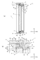
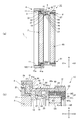
- FIG. 1 is a perspective view of a camera filter unit according to Embodiment 1.
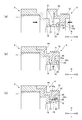
- FIG. FIG. 2 is a longitudinal sectional view and a partially enlarged sectional view of a camera filter unit according to the first embodiment. It is explanatory drawing of the assembly method of the filter unit for cameras.
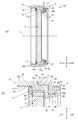
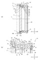
- FIG. 6 is a longitudinal sectional view and a partially enlarged sectional view of a camera filter unit according to a second embodiment.
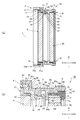
- FIG. 6 is a longitudinal sectional view and a partially enlarged sectional view of a camera filter unit according to a third embodiment.
- FIG. 6 is a longitudinal sectional view and a partially enlarged sectional view of a camera filter unit according to a fourth embodiment.
- FIG. 9 is a longitudinal sectional view and a partially enlarged sectional view of a camera filter unit according to a fifth embodiment.
- FIG. 1 is a perspective view of the camera filter unit according to the first embodiment.
- 2A is a longitudinal sectional view of the camera filter unit of FIG. 1
- FIG. 2B is a partially enlarged sectional view thereof.
- a camera filter unit 1 of this example includes a disk-shaped polarizing filter (optical element) 2, an inner ring 3 that holds the polarizing filter 2 coaxially, and an inner ring. 3 is provided with a front ring 4 that coaxially holds 3 from the outer peripheral side, and a rear ring 5 that holds the front ring 4 coaxially.
- the front ring 4 holds the polarizing filter 2 via the inner ring 3.
- the rear ring 5 holds the front ring 4 so as to be rotatable around the axis L.
- the inner ring 3, the front ring 4 and the rear ring 5 constitute a camera filter frame 10.
- the direction along the axis L of the inner ring 3, the front ring 4, and the rear ring 5 is defined as the front-rear direction X of the camera filter unit 1.
- the side where the front ring 4 is located is the front side (front X1)
- the side where the rear ring 5 is located is the rear side (rear X2).
- the front ring 4 holds the inner ring 3 at a position where it is not exposed from the front end.
- a female screw 11 is provided in a region having a constant width from the front end edge toward the rear X 2.
- An exposed portion of the female screw 11 exposed to the front side of the inner ring 3 is a front mounting portion for mounting a cap or a hood on the front side of the camera filter unit 1.
- On the outer peripheral surface of the rear ring 5, a male screw 12 is provided in an area having a constant width from the rear edge toward the front X ⁇ b> 1.
- the male screw 12 is a rear mounting portion for mounting the camera filter unit 1 to a lens barrel or camera of an imaging lens.
- the inner ring 3, the front ring 4 and the rear ring 5 are all formed from a metal substrate. In this example, the inner ring 3, the front ring 4 and the rear ring 5 are all made of aluminum.
- the front ring 4 includes a front annular plate portion 15 extending in the front-rear direction X along the axis L, and an axis L extending from the rear end portion of the front annular plate portion 15 toward the inner peripheral side.
- a front annular wall portion 16 extending in an orthogonal radial direction R, an intermediate annular plate portion 17 extending from the inner peripheral side end portion of the front annular wall portion 16 along the axis L to the rear X2, and a rear end portion of the intermediate annular plate portion 17
- a rear annular wall portion (annular wall portion) 18 extending in the radial direction R from the inner circumferential side to the inner circumferential side, a rear annular plate portion 19 extending from the inner circumferential side end portion of the rear annular wall portion 18 to the rear X2, and
- An annular projecting portion 20 projecting from the rear end portion of the rear annular plate portion 19 toward the outer peripheral side with a shorter dimension than the rear annular wall portion 18 is provided.
- An annular recess 21 is formed on the outer peripheral surface of the front ring 4 by a rear annular wall portion 18, a rear annular plate portion 19 and an annular projecting portion 20.
- the front annular plate portion 15 includes a thick portion 23 and a thin portion 24 in this order from the front X1 toward the rear X2.
- the thick portion 23 protrudes more outward than the thin portion 24.
- An annular step portion 25 is formed on the outer peripheral surface of the front annular plate portion 15 by the thick portion 23 and the thin portion 24.
- a female screw 11 serving as a front mounting portion is formed on the inner peripheral surface of the front annular plate portion 15.
- the thickness of the front annular wall portion 16 in the front-rear direction X is constant.
- the intermediate annular plate portion 17 has a constant thickness dimension in the radial direction R.
- the rear annular wall portion 18 has a constant thickness dimension in the front-rear direction X.
- the rear annular plate portion 19 is inclined toward the outer peripheral side toward the rear X2. More specifically, an annular groove 27 is provided in a front end portion (a portion adjacent to the rear annular wall portion 18) of the outer peripheral surface of the rear annular plate portion 19, and the rear annular plate portion 19 is formed in the annular groove 27.
- the portion where the is formed is inclined to the outer peripheral side by being bent to the outer peripheral side. That is, the rear annular plate portion 19 is a bent portion where the portion where the annular groove 27 is formed is bent toward the outer peripheral side.
- An annular notch 28 is provided on the rear portion of the outer peripheral surface of the rear annular plate portion 19 (the portion adjacent to the annular protruding portion 20). The notch 28 is shallower than the annular groove 27.
- the annular projecting portion 20 projects in a direction perpendicular to the rear annular plate portion 19. Accordingly, the annular projecting portion 20 extends forward X1 toward the outer peripheral side.
- the cross-sectional shape of the annular projecting portion 20 is a trapezoid that narrows toward the tip side.
- the inner peripheral side portion of the annular protrusion 45 provided on the rear ring 5 is inserted. Has been.
- the inner ring 3 includes an annular frame 31 that holds the polarizing filter 2 coaxially from the outer peripheral side, and an annular front stopper that protrudes from the front end edge of the annular frame 31 toward the inner peripheral side and restricts the movement of the polarizing filter 2 toward the front X1. 32.
- the front stopper 32 can come into contact with the outer peripheral edge portion of the polarizing filter 2 held by the annular frame 31 from the front X1.
- the inner peripheral surface of the annular frame 31 is an annular surface extending with a constant diameter along the axis L, and is a filter holding surface 33 that holds the polarizing filter 2 coaxially.
- the annular frame 31 includes a thick frame portion 34 and a thin frame portion 35 in this order from the front X1 toward the rear X2.
- the outer peripheral surface of the thick frame portion 34 is positioned on the outer peripheral side with respect to the outer peripheral surface of the thin frame portion 35, and an annular rearward surface 34 a extending along the radial direction R is formed therebetween.
- a male screw 36 that can be screwed with the female screw 11 of the front ring 4 is formed on the outer peripheral surface of the thick frame portion 34.
- An adhesive injection hole 37 that penetrates in the radial direction R and opens to the filter holding surface 33 is formed in the thin frame portion 35.
- the polarizing filter 2 is attached to the inner ring 3 by this adhesive.
- the number of adhesive injection holes 37 may be one, but in this example, a plurality of thin frame portions 35 are provided at equal angular intervals.
- the front stopper 32 is an annular protrusion protruding from the front edge of the annular frame 31 toward the inner peripheral side.
- the front stopper 32 includes a flat annular rear end surface 32 a that is orthogonal to the axis L.
- the width dimension (width dimension W of the filter holding surface 33) from the annular rear end surface 32a of the front stopper 32 to the rear end of the annular frame 31 is the thickness dimension D of the polarizing filter 2 held by the filter holding surface 33. Longer than.
- the difference between the width dimension W in the front-rear direction X of the filter holding surface 33 and the thickness dimension D of the polarizing filter 2 is 0.03 mm or less.
- the inner ring 3 is inserted from the front side into the front ring 4 with the polarizing filter 2 held on the inner peripheral side of the annular frame 31. Then, the male screw 36 is screwed into the female screw 11 of the front ring 4 and is screwed in until the rear end of the annular frame 31 contacts the rear annular wall portion 18 of the front ring 4. When the rear end of the annular frame 31 comes into contact with the rear annular wall portion 18, the annular rear surface 34 a of the inner ring 3 and the front annular wall portion 16 of the front ring 4 face each other in the front-rear direction X with a minute gap therebetween.
- the outer peripheral surface of the thin frame portion 35 of the annular frame 31 and the intermediate annular plate portion 17 are opposed to each other with a small gap in the radial direction R.
- the distance (the width dimension W of the filter holding surface 33) between the front stopper 32 and the rear annular wall portion 18 in a state where the rear end of the annular frame 31 is in contact with the rear annular wall portion 18 is the polarization. It is longer than the thickness dimension D of the filter 2. Accordingly, the front ring 4 holds the polarizing filter 2 so as to be rotatable about the axis L between the front stopper 32 and the rear annular wall portion 18.
- the front stopper 32 and the rear annular wall portion 18 do not hold the polarizing filter 2 in a non-rotatable manner, and the polarizing filter 2 is fixed to the inner ring 3 in a non-rotatable manner by an adhesive.
- the rear annular wall portion 18 functions as a rear stopper that prevents the polarizing filter 2 from moving backward X2.
- the annular rear surface 34 a of the inner ring 3 and the front annular shape of the front ring 4 are provided.
- the wall portion 16 may abut.
- the rear ring 5 includes a front annular plate portion 41 extending in the front-rear direction X along the axis L, an annular wall portion 42 extending in the radial direction R from the rear end portion of the front annular plate portion 41 toward the inner peripheral side, and an annular wall A rear annular plate portion 43 extending from the end portion on the inner peripheral side of the portion 42 to the rear X2 along the axis L is provided.
- the front annular plate portion 41 has a constant thickness dimension in the radial direction R.
- a grease holding recess 44 is formed on the front end surface of the annular wall portion 42. The grease holding recess 44 holds grease for smoothly sliding the front ring 4 and the rear ring 5.
- a male screw 12 serving as a rear mounting portion is formed on the outer peripheral surface of the rear annular plate portion 43.
- An annular protrusion 45 that protrudes in the radial direction R toward the inner peripheral side is provided on the inner peripheral surface of the rear annular plate portion 43.
- the annular protrusion 45 has a rectangular cut shape.
- the annular protrusion 45 has a width dimension in the front-rear direction X that is longer than a protrusion dimension toward the inner periphery.
- the annular protrusion 45 is formed at a position overlapping the male screw 12 when viewed from the radial direction R.
- the front annular plate portion 41 is slidably fitted to the annular step portion 25 of the front ring 4.
- the outer peripheral surface 41a of the front annular plate portion 41 and the outer peripheral surface 15a of the thick portion 23 of the front annular plate portion 15 of the front ring 4 are continuous without a step.
- the annular wall portion 42 contacts the front annular wall portion 16 of the front ring 4 from the rear X2, and the rear annular plate portion 43 contacts the intermediate annular plate portion 17 of the front ring 4 from the outer peripheral side.
- the annular protrusion 45 contacts the rear annular wall portion 18 of the front ring 4 from the rear X2.
- the inner peripheral side portion of the annular protrusion 45 is inserted into the annular recess 21 on the outer peripheral surface of the inner ring 3.
- the rear ring 5 holds the front ring 4 so as to be rotatable around the axis L.
- FIG. 3 is an explanatory view of the assembling operation of the camera filter unit 1.
- the front ring 4 and the rear ring 5 are combined from the front-rear direction X, and the annular protrusion 45 of the rear ring 5 is rear-circular in the front-rear direction X. It is located between the wall portion 18 and the annular protruding portion 20.
- the rear annular plate portion 19 of the front ring 4 extends along the axis L as shown in FIG. Therefore, the annular projecting portion 20 projects in the radial direction R from the rear end portion of the rear annular plate portion 19, and the outer peripheral end surface 20 a extends in parallel with the axis L.
- the annular groove 27 has a rectangular cross section.
- the notch 28 is notched downward toward the rear X2, and its cross-sectional shape is a triangle.
- the outer peripheral side end surface 20 a of the annular projecting portion 20 of the front ring 4 is the same as the inner peripheral side end surface 45 a of the annular protrusion 45 of the rear ring 5. It is located on the surface or slightly located on the inner peripheral side with respect to the inner peripheral side end face 45a. Accordingly, the front ring 4 and the rear ring 5 are brought close to each other while keeping the front ring 4 and the rear ring 5 coaxial, so that the annular protrusion 45 of the rear ring 5 is moved to the rear annular wall portion 18 of the front ring 4. And the annular projecting portion 20.
- the annular protrusion 45 of the rear ring 5 is brought into contact with the rear annular wall portion 18 of the front ring 4 from the rear X2. Then, the rear annular plate portion 19 of the front ring 4 is bent to the outer peripheral side (plastically deformed), and the annular projecting portion 20 is displaced to the outer peripheral side. Thereby, the state where the annular protrusion 45 of the rear ring 5 is inserted into the annular recess 21 of the front ring 4 is formed.
- the annular groove 27 by forming the annular groove 27, a thin portion is provided at the front end of the rear annular plate portion 19, and this thin portion is bent to the outer peripheral side. Therefore, the rear annular plate portion 19 can be bent with high accuracy with a relatively weak force. Thereby, since the annular protrusion part 20 can be displaced to the outer peripheral side with high accuracy, the dimensional accuracy between the annular protrusion 45 of the rear ring 5 and the annular recess 21 of the front ring 4 can be improved. Therefore, the annular projecting portion 20 of the front ring 4 can be opposed to each other with a small gap G set in advance behind the annular projection 45 of the rear ring 5. In this example, the gap G can be between 0.03 mm and 0.1 mm. Therefore, it is possible to prevent the front ring 4 from rattling with respect to the rear ring 5 when the front ring 4 is rotated. Further, the front ring 4 can be smoothly rotated with respect to the rear ring 5.
- the polarizing filter 2 is inserted into the inner ring 3 from the rear X2, and the polarizing filter 2 is brought into contact with the front stopper 32. Further, an adhesive is injected from the adhesive injection hole 37 to fix the polarizing filter 2 to the inner ring 3. Then, the inner ring 3 is screwed into the front ring 4 from the front X1, and the rear end of the annular frame 31 of the inner ring 3 is brought into contact with the rear annular wall portion 18 of the front ring 4. Thus, the camera filter unit 1 is completed. In the state in which the camera filter unit 1 is completed, the polarizing filter 2 is held by the front ring 4 while being rotatable about the axis L between the front stopper 32 and the rear annular wall portion 18. Is fixed to the inner ring 3 in a non-rotatable manner.
- an adhesive may be applied to the front surface of the annular rear surface 34a of the inner ring 3 or the front annular wall portion 16 of the front ring 4, and the inner ring 3 may be fixed to the front ring 4 with this adhesive.
- the front ring 4 can rotate around the axis L using the annular protrusion 45 of the rear ring 5 inserted into the annular recess 21 as a guide. Therefore, it is not necessary to use a washer to hold the front ring 4 rotatably by the rear ring 5.
- the guide annular protrusion 45
- the annular protrusion 45 serving as a guide can be formed more accurately than a washer that expands and contracts in the radial direction.
- the annular projecting portion 20 can be accurately displaced to the outer peripheral side, the dimensional accuracy between the annular protrusion 45 of the rear ring 5 and the annular recess 21 of the front ring 4 is high.
- another member such as a washer is not interposed between the front ring 4 and the rear ring 5, the front ring 4 and the rear ring 5 can be combined with high accuracy. Accordingly, the front ring 4 held by the rear ring 5 can be smoothly rotated.
- the annular protrusion 45 of the rear ring 5 is provided at a position overlapping the male screw 36 when viewed from the radial direction R. Therefore, the camera filter frame 10 can be shortened in the front-rear direction X as compared with the case where the annular protrusion 45 and the male screw 36 are formed at different positions in the axis L direction.
- the polarizing filter 2 is held by the front ring 4 in a state of being rotatable around the axis L between the front stopper 32 and the rear annular wall portion 18, and is fixed to the inner ring 3 so as not to rotate by an adhesive. Yes. Therefore, compared with the case where the polarizing filter 2 is sandwiched from the front and rear by the front stopper 32 and the rear annular wall portion 18 (rear stopper) and held on the front ring 4 in a non-rotatable state, the stress applied to the polarizing filter 2 is increased. (Pressure) can be reduced. If the stress applied to the polarizing filter 2 is small, it is possible to prevent the polarizing filter 2 from being distorted. For example, when taking high-resolution images that are many times higher than full high-definition, it is possible to obtain more beautiful images and images. You can get a video.
- the adhesive injection hole 37 is formed in the inner ring 3 held on the inner peripheral side of the front ring 4, the adhesive injection hole 37 is exposed to the outer peripheral side and the appearance of the camera filter frame 10. Will not be damaged.
- the polarizing filter 2 is moved to the front stopper when the rear end of the annular frame 31 is brought into contact with the rear annular wall portion 18. It is also possible to adopt a configuration in which it is clamped between the rear annular wall portion 18 and the rear annular wall portion 18 so as not to rotate.
- Example 2 is a longitudinal sectional view of the camera filter unit according to the second embodiment, and FIG. 4B is a partially enlarged sectional view thereof.
- the camera filter unit 1A of this example includes a disk-shaped polarizing filter (optical element) 2, a front ring 4 that holds the polarizing filter 2 coaxially, and the front ring 4 as an axis.
- a rear ring 5 is provided that is rotatably held around L.
- the camera filter unit 1A includes a front stopper 6 that is attached to the inner peripheral surface of the front ring 4 and restricts the movement of the polarizing filter 2 toward the front X1.
- the front ring 4, the rear ring 5, and the front stopper 6 constitute a camera filter frame 10A. Since the camera filter unit 1A of the present example has a configuration corresponding to the camera filter unit 1, the corresponding portions will be described with the same reference numerals.
- a female thread 11 is provided on the inner peripheral surface of the front ring 4 in a region having a constant width from the front edge toward the rear X2.
- the front portion of the female screw 11 that is exposed in front of the front stopper 6 is a front mounting portion for mounting a cap or a hood on the front side of the camera filter unit 1A.
- the male screw 36 is a rear mounting portion for mounting the camera filter unit 1A to the lens barrel or camera of the imaging lens.
- the front stopper 6, the front ring 4 and the rear ring 5 are all formed from a metal base material. In this example, the front stopper 6, the front ring 4 and the rear ring 5 are made of aluminum.
- the front ring 4 includes a front annular plate portion 15 that extends in the front-rear direction X along the axis L, and a front end portion of the front annular plate portion 15 that is continuous with the rear end portion of the front annular plate portion 15.
- An intermediate annular plate portion (holding portion) 17 extending rearward X2 along the axis L on the inner peripheral side of the inner peripheral side of the intermediate annular plate portion 17 and extending from the rear end portion of the intermediate annular plate portion 17 toward the inner peripheral side in the radial direction R perpendicular to the axis L.
- annular plate portion 19 extending rearward X 2 from the inner peripheral end portion of the rear annular wall portion 18, and the rear end portion of the rear annular plate portion 19
- An annular projecting portion 20 projecting toward the outer peripheral side with a shorter dimension than the rear annular wall portion 18 is provided.
- An annular step portion 25 is formed on the outer peripheral surface of the front ring 4 by the front annular plate portion 15 and the intermediate annular plate portion 17.
- An annular recess 21 is formed on the outer peripheral surface of the front ring 4 by the rear annular wall portion 18, the rear annular plate portion 19 and the annular projecting portion 20.
- a female screw 11 serving as a front mounting portion is formed on the inner peripheral surface of the front annular plate portion 15.
- the intermediate annular plate portion 17 has a constant thickness dimension in the radial direction R.
- the inner peripheral surface of the intermediate annular plate portion 17 (the surface located between the front end surface of the intermediate annular plate portion 17 and the front end surface of the rear annular wall portion 18) is an annular surface extending along the axis L with a constant radial dimension.
- the width dimension W of the filter holding surface 17a is longer than the thickness dimension D of the polarizing filter 2 held by the filter holding surface 17a.
- the difference between the width dimension W of the filter holding surface 17a and the thickness dimension D of the polarizing filter 2 is 0.03 mm or less.
- the rear annular wall portion 18 has a constant thickness dimension in the front-rear direction X.
- the rear annular wall portion 18 functions as a rear stopper that restricts the backward movement of the polarizing filter 2 held by the filter holding surface 17a.
- the rear annular plate portion 19 is inclined toward the outer peripheral side toward the rear X2. More specifically, an annular groove 27 is provided in a front end portion (a portion adjacent to the rear annular wall portion 18) of the outer peripheral surface of the rear annular plate portion 19, and the rear annular plate portion 19 is formed in the annular shape. The portion where the groove 27 is formed is inclined to the outer peripheral side by being bent to the outer peripheral side. An annular notch 28 is provided on the rear portion of the outer peripheral surface of the rear annular plate portion 19 (the portion adjacent to the annular protruding portion 20). The notch 28 is shallower than the annular groove 27.
- the annular projecting portion 20 projects in a direction perpendicular to the rear annular plate portion 19. Accordingly, the annular projecting portion 20 extends forward X1 toward the outer peripheral side.
- the cross-sectional shape of the annular projecting portion 20 is a trapezoid that narrows toward the tip side.
- the inner peripheral side portion of the annular protrusion 45 of the rear ring 5 is inserted into the annular recess 21 formed by the rear annular wall portion 18, the rear annular plate portion 19 and the annular projecting portion 20. .
- the front stopper 6 has a ring shape.
- the front stopper 6 has a height dimension in the radial direction R that is longer than a height dimension in the radial direction R of the intermediate annular plate portion 17 of the front ring (the thickness of the intermediate annular plate portion 17).
- the front stopper 6 includes a flat annular rear end surface 6 a that is orthogonal to the axis L.
- a male screw 51 that can be screwed with the female screw 11 of the front ring 4 is formed on the entire outer peripheral surface of the front stopper 6.
- the front stopper 6 is screwed in such a manner that the male screw 51 is screwed into the female screw 11 of the front ring 4 and the annular rear end face 6 a comes into contact with the front end face of the intermediate annular plate portion 17.
- the front stopper 6 In a state where the front stopper 6 is in contact with the intermediate annular plate portion 17, the end portion on the inner peripheral side of the front stopper 6 protrudes to the inner peripheral side from the filter holding surface 17 a. Accordingly, the front stopper 6 can restrict the movement of the polarizing filter 2 held on the filter holding surface 17a to the front X1.
- the front ring 4 includes a front annular plate portion (annular portion) 41 extending in the front-rear direction X along the axis L, and an annular wall portion extending in the radial direction R from the rear end portion of the front annular plate portion 41 toward the inner peripheral side. 42, a rear annular plate portion 43 extending from the inner peripheral side end portion of the annular wall portion 42 along the axis L to the rear X2.
- the front annular plate portion 41 has a constant thickness dimension in the radial direction R.
- a grease holding recess 44 is formed on the front end surface of the annular wall portion 42. The grease holding recess 44 holds grease for smoothly sliding the front ring 4 and the rear ring 5.
- a male screw 12 serving as a rear mounting portion is formed on the outer peripheral surface of the rear annular plate portion 43.
- annular protrusion 45 that protrudes in the radial direction R toward the inner peripheral side.
- the annular protrusion 45 has a rectangular cut shape.
- the front end surface of the annular protrusion 45 is continuous with the front end surface of the annular wall portion 42 without a step.
- the annular protrusion 45 has a width dimension in the front-rear direction X that is longer than a protrusion dimension toward the inner peripheral side.
- the annular protrusion 45 is formed at a position partially overlapping with the male screw 12 when viewed from the radial direction R.
- the front annular plate portion 41 is slidably fitted to the annular step portion 25 of the front ring 4.
- the outer peripheral surface 41a of the front annular plate portion 41 and the outer peripheral surface 15a of the front annular plate portion 15 of the front ring 4 are continuous without a step.
- the rear annular plate portion 43 is in contact with the rear end surface of the intermediate annular plate portion 17 of the front ring 4 from the rear X2.
- the annular protrusion 45 is in contact with the rear end surface of the rear annular wall portion 18 of the front ring 4 from the rear X2.
- the inner peripheral side portion of the annular protrusion 45 is inserted into the annular recess 21 provided on the outer peripheral surface of the front stopper 6.
- the rear ring 5 holds the front ring 4 so as to be rotatable around the axis L.
- the polarizing filter 2 is inserted into the front ring 4 from the front X1, and the polarizing filter 2 is held on the filter holding surface 17a. Then, the front stopper 6 is screwed into the front ring 4 from the front X 1, and the annular rear end face 6 a of the front stopper 6 is brought into contact with the intermediate annular plate portion 17 of the front ring 4. Thus, the camera filter unit 1A is completed. When the camera filter unit 1A is completed, the polarizing filter 2 is held by the front ring 4 so as to be rotatable about the axis L between the front stopper 6 and the rear annular wall portion 18.
- an adhesive may be applied to the annular rear end surface 6a of the front stopper 6 or the front end surface of the intermediate annular plate portion 17 of the front ring 4, and the front stopper 6 may be fixed to the front ring 4 with this adhesive.
- the front ring 4 can rotate around the axis L using the annular protrusion 45 of the rear ring 5 inserted into the annular recess 21 as a guide. Therefore, it is not necessary to use a washer to hold the front ring 4 rotatably by the rear ring 5.
- the guide annular protrusion 45
- the annular protrusion 45 serving as a guide can be formed more accurately than a washer that expands and contracts in the radial direction.
- the annular projecting portion 20 can be accurately displaced to the outer peripheral side, the dimensional accuracy between the annular protrusion 45 of the rear ring 5 and the annular recess 21 of the front ring 4 is high.
- another member such as a washer is not interposed between the front ring 4 and the rear ring 5, the front ring 4 and the rear ring 5 can be combined with high accuracy. Accordingly, the front ring 4 held by the rear ring 5 can be smoothly rotated.
- the annular protrusion 45 of the rear ring 5 is provided at a position overlapping the male screw 51 when viewed from the radial direction R, the annular protrusion 45 and the mounting portion are formed at different positions in the axis L direction. Compared to the case, the camera filter frame 10A can be shortened in the front-rear direction X.
- the front ring 4 holds the polarizing filter 2 so as to be rotatable around the axis L between the front stopper 6 and the rear annular wall portion 18. Accordingly, the stress (pressure) applied to the polarizing filter 2 is reduced compared to the case where the polarizing filter 2 is sandwiched from the front and rear by the front stopper 6 and the rear annular wall portion 18 (rear stopper) to be unable to rotate. It is possible to prevent the polarizing filter 2 from being distorted.
- an adhesive injection hole 37 that penetrates in the direction intersecting the axis L and opens to the filter holding surface 17a is provided in the intermediate annular plate portion 17 of the front ring 4. be able to.
- the adhesive injection hole 37 is provided, the polarizing filter 2 can be fixed to the front ring 4 by injecting the adhesive through the adhesive injection hole 37.
- the intermediate annular plate portion 17 is located on the inner peripheral side of the front annular plate portion 41 of the rear ring 5. Therefore, even when the adhesive injection hole 37 is formed in the intermediate annular plate portion 17, the adhesive injection hole 37 is not exposed to the outer peripheral side and the appearance of the camera filter frame 10 is not damaged.
- the width dimension W of the filter holding surface 17a is made the same as the thickness dimension D of the polarizing filter 2, and the polarizing filter 2 is sandwiched between the front stopper 6 and the rear annular wall portion 18 so as not to rotate. It can also be adopted.
- FIG. 5A is a longitudinal sectional view of the camera filter unit according to the third embodiment
- FIG. 5B is a partially enlarged sectional view thereof.
- the camera filter unit 1B of this example includes a disk-shaped polarizing filter (optical element) 2, an inner ring 3 that holds the polarizing filter 2 coaxially, and a front ring 4 that holds the inner ring 3 coaxially from the outer peripheral side.
- the rear ring 5 is provided to hold the front ring 4 coaxially.
- the camera filter unit 1B of this example is inserted into the disc-shaped second polarizing filter (second optical element) 60 and the rear ring 5 from the rear, and holds the second polarizing filter 60 coaxially.
- a rear inner ring 61 is provided.
- the rear inner ring 61 is made of aluminum.
- the front ring 4 holds the polarizing filter 2 via the inner ring 3.
- the rear ring 5 holds the second polarizing filter 60 via the rear inner ring 61.
- the rear ring 5 holds the front ring 4 so as to be rotatable around the axis L.
- the inner ring 3, the front ring 4, the rear ring 5, and the rear inner ring 61 constitute a camera filter frame 10B.
- the holding structure of the polarizing filter 2 in which the front ring 4 holds the polarizing filter 2 is the same as that of the camera filter unit 1 of the first embodiment.
- the holding structure of the front ring 4 in which the rear ring 5 holds the front ring 4 so as to be rotatable around the axis L is the same as that of the camera filter units 1 and 1A of the first and second embodiments. Therefore, hereinafter, a holding structure in which the rear ring 5 holds the second polarizing filter 60 will be described. Further, parts common to the camera filter unit 1 of the first embodiment are denoted by the same reference numerals, and description thereof is omitted.
- the holding structure of the polarizing filter 2 in which the front ring 4 holds the polarizing filter 2 may be the same as the holding structure of the camera filter unit 1A in the second embodiment.
- the rear ring 5 includes a second annular projecting portion (second annular projecting portion, second front stopper) 64 that projects to the inner peripheral side at the rear X2 from the front ring 4. .
- the rear ring 5 includes a thick portion 65 and a female screw 66 on the rear side of the second annular projecting portion 64. More specifically, the rear annular plate portion 43 of the rear ring 5 extends to the rear X2 longer than the camera filter units 1 and 1A of the first and second embodiments.
- a second annular projecting portion 64, a thick portion 65, and a female screw 66 are provided.
- the second annular projecting portion 64 projects in the radial direction R toward the inner peripheral side at a position separated from the rear X2 of the annular projecting portion 45.
- the annular projecting portion 20 of the front ring 4 is located between the annular projecting portion 45 and the second annular projecting portion 64.
- the thick portion 65 extends from the midway position in the radial direction R of the second annular projecting portion 64 to the rear X2 with a constant thickness.
- the second annular projecting portion 64 includes a first annular rearward surface 64 a on the outer peripheral side of the thick portion 65.
- the female screw 66 is provided continuously behind the thick portion 65 at the rear X2.
- the thick portion 65 is provided with a second annular rear surface 65 a between the internal thread 66.
- a male screw 12 serving as a rear mounting portion is provided on the outer peripheral surface of the rear end portion of the rear ring 5 (the outer peripheral surface of the rear end portion of the rear annular plate portion 43).
- the rear inner ring 61 has a rear annular frame 70 that holds the second polarizing filter 60 coaxially from the outer peripheral side, and projects from the rear end edge of the rear annular frame 70 toward the inner peripheral side to the rear of the second polarizing filter 60.
- a second rear stopper (second rear stopper) 71 that restricts movement to X2 is provided.
- the second rear stopper 71 can come into contact with the outer peripheral edge portion of the second polarizing filter 60 held by the rear annular frame 70 from the rear X2.
- the inner peripheral surface of the rear annular frame 70 is an annular surface extending with a constant diameter along the axis L, and is a rear filter holding surface 72 that holds the second polarizing filter 60 coaxially.
- the rear inner ring 61 includes a thin ring portion 73 and a thick ring portion 74 in this order from the front X1 toward the rear X2.
- the outer peripheral surface of the thick ring portion 74 is located on the outer peripheral side of the outer peripheral surface of the thin ring portion 73, and an annular forward surface 74 a extending along the radial direction R is formed between them.
- On the outer peripheral surface of the thick ring portion 74 a male screw 75 that can be screwed with the female screw 66 of the rear ring 5 is formed.
- the thin ring portion 73 is formed with a rear adhesive injection hole 76 that penetrates in the radial direction R and opens to the rear filter holding surface 72.
- the adhesive is injected from the outer peripheral side of the rear annular frame 70 through the rear adhesive injection hole 76 with the second polarizing filter 60 held on the rear filter holding surface 72, this adhesive
- the second polarizing filter 60 can be fixed to the rear inner ring 61.
- the number of the rear adhesive injection holes 76 may be one, but in this example, a plurality of thin ring portions 73 are provided at equal angular intervals. Further, the rear adhesive injection hole 76 may be omitted.
- the second rear stopper 71 is an annular protrusion protruding from the rear edge of the rear annular frame 70 toward the inner peripheral side.
- the second rear stopper 71 includes a flat annular front end surface 71 a that is orthogonal to the axis L.
- a width dimension (width dimension of the rear filter holding surface 72) W2 from the annular front end surface 71a of the second rear stopper 71 to the front end 70a of the rear annular frame 70 is held by the filter holding surface 33. It is longer than the thickness dimension D2 of the two-polarizing filter 60.
- the difference between the width dimension W2 of the rear filter holding surface 72 in the front-rear direction X and the thickness dimension D2 of the second polarizing filter 60 is 0.03 mm or less.
- the rear inner ring 61 is inserted from the rear side into the rear ring 5 with the second polarizing filter 60 held on the inner peripheral side of the rear annular frame 70. Then, the male screw 75 is screwed into the female screw 66 of the rear ring 5 so that the front end 70a of the rear annular frame 70 is in contact with the second annular projecting portion 64 (first annular rearward surface 64a) of the rear ring 5. It is screwed in until it comes into contact. When the front end 70a of the rear annular frame 70 comes into contact with the second annular projecting portion 64, a small gap is formed between the annular front surface 74a of the rear inner ring 61 and the second annular rear surface 65a of the rear ring 5. Opposite in the front-rear direction X. Further, the outer peripheral surface of the thin ring portion 73 of the rear annular frame 70 and the thick portion 65 of the rear ring 5 face each other with a small gap in the radial direction R.
- the width dimension W2 is longer than the thickness dimension D2 of the second polarizing filter 60. Therefore, the rear ring 5 holds the second polarizing filter 60 so as to be rotatable about the axis L between the second rear stopper 71 and the second annular projecting portion 64. That is, the second rear stopper 71 and the second annular projecting portion 64 do not hold the second polarizing filter 60 in a non-rotatable manner, and the second polarizing filter 60 cannot be rotated on the rear inner ring 61 by an adhesive. Fixed.
- the second annular projecting portion 64 functions as a second front stopper that prevents the second polarizing filter 60 from moving forward X1.
- the second polarizing filter 60 is held on the rear ring 5. Therefore, in this example, two optical filters (the polarizing filter 2 and the second polarizing filter 60) can be held in the camera filter frame 10B. Further, the rear ring 5 holds the second polarizing filter 60 so as to be rotatable around the axis L between the second rear stopper 71 and the second annular projecting portion 64.
- the stress (pressure) applied to the second polarizing filter 60 is reduced. Can be reduced. Therefore, it is possible to prevent the second polarizing filter 60 from being distorted.
- the rear adhesive injection hole 76 is formed in the rear inner ring 61 held on the inner peripheral side of the rear ring 5, the rear adhesive injection hole 76 is exposed to the outer peripheral side. The appearance of the camera filter frame 10B is not damaged.
- the width dimension W2 of the rear filter holding surface 72 is set to be the same as the thickness dimension D2 of the second polarizing filter 60, and the second polarizing filter 60 is located between the second rear stopper 71 and the second annular projecting portion 64. It is also possible to adopt a configuration that is held in a non-rotatable manner.
- the female screw 66 of the rear ring 5 and the male screw 75 of the rear inner ring 61 may be omitted, and the rear inner ring 61 may be fixed to the inner peripheral side of the rear ring 5 with an adhesive.
- the optical element held by the front ring 4 and the rear ring 5 is not limited to the polarizing filter.
- a polarizing filter can be held on the front ring 4 and a color filter can be held on the rear ring 5.
- a cross filter can be held on the front ring 4 and a color filter can be held on the rear ring 5.
- FIG. 6A is a longitudinal sectional view of the camera filter unit according to the fourth embodiment, and FIG. 6B is a partially enlarged sectional view thereof.
- the camera filter unit 1C of this example includes a disk-shaped polarizing filter (optical element) 2, an inner ring 3 that holds the polarizing filter 2 coaxially, and a front ring 4 that holds the inner ring 3 coaxially from the outer peripheral side.
- the rear ring 5 is provided to hold the front ring 4 coaxially.
- the camera filter unit 1C of this example is inserted into the disc-shaped second polarizing filter (second optical element) 60 and the rear ring 5 from the rear X2, and holds the second polarizing filter 60 coaxially.
- a rear inner ring 81 is provided.
- the rear inner ring 81 is made of aluminum.
- the front ring 4 holds the polarizing filter 2 via the inner ring 3.
- the rear ring 5 holds the second polarizing filter 60 via the rear inner ring 81.
- the rear ring 5 holds the front ring 4 so as to be rotatable around the axis L.
- the inner ring 3, the front ring 4, the rear ring 5, and the rear inner ring 81 constitute a camera filter frame 10C.
- the holding structure of the polarizing filter 2 in which the front ring 4 holds the polarizing filter 2 is the same as that of the camera filter unit 1 of the first embodiment.
- the holding structure of the front ring 4 in which the rear ring 5 holds the front ring 4 so as to be rotatable around the axis L is the same as that of the camera filter units 1 and 1A of the first and second embodiments. Therefore, hereinafter, a holding structure in which the rear ring 5 holds the second polarizing filter 60 will be described. Further, parts common to the camera filter unit 1 of the first embodiment are denoted by the same reference numerals, and description thereof is omitted.
- the holding structure of the polarizing filter 2 in which the front ring 4 holds the polarizing filter 2 may be the holding structure of the camera filter unit 1A in the second embodiment.
- the rear ring 5 includes a second annular projecting portion (second annular projecting portion, second front stopper) 84 projecting inward from the front ring 4 toward the rear X2. .
- the rear ring 5 includes a female screw 85 on the rear side of the second annular projecting portion 84. More specifically, the rear annular plate portion 43 of the rear ring 5 extends to the rear X2 longer than the camera filter units 1 and 1A of the first and second embodiments, and is formed on the inner peripheral surface thereof.
- Two annular projecting portions 84 and a female screw 85 are provided.
- the second annular projecting portion 84 projects in the radial direction R toward the inner peripheral side at a position separated from the rear X2 of the annular projecting portion 45.
- the annular projecting portion 20 of the front ring 4 is located between the annular projecting portion 45 and the second annular projecting portion 84.
- the female screw 85 is provided continuously to the rear X2 of the second annular projecting portion 84.
- the second annular projecting portion 84 includes an annular rear surface 84 a between the female screw 85.
- a male screw 12 serving as a rear mounting portion is provided on the outer peripheral surface of the rear end portion of the rear ring 5 (the outer peripheral surface of the rear end portion of the rear annular plate portion 43).
- the rear inner ring 81 has a rear annular frame 86 that holds the second polarizing filter 60 coaxially from the outer peripheral side, and projects rearward from the rear edge of the rear annular frame 86 to the inner peripheral side.
- a second rear stopper (second rear stopper) 87 that restricts movement to X2 is provided.
- the second rear stopper 87 can come into contact with the outer peripheral edge portion of the second polarizing filter 60 held by the rear annular frame 86 from the rear X2.
- the inner peripheral surface of the rear annular frame 86 is an annular surface extending with a constant diameter along the axis L, and is a rear filter holding surface 88 that holds the second polarizing filter 60 coaxially.
- a male screw 89 that can be screwed with the female screw 85 of the rear ring 5 is formed on the outer peripheral surface of the rear inner ring 81.
- a rear adhesive injection hole 90 that penetrates in the radial direction R and opens to the rear filter holding surface 88 is formed in the rear annular frame 86.
- the adhesive is injected from the outer peripheral side of the rear annular frame 86 through the rear adhesive injection hole 90 with the second polarizing filter 60 held on the rear filter holding surface 88, this adhesive
- the second polarizing filter 60 can be fixed to the rear inner ring 81.
- the number of the rear adhesive injection holes 90 may be one, but in this example, a plurality of thin ring portions 73 are provided at equal angular intervals. Further, the rear adhesive injection hole 90 may be omitted.
- the second rear stopper 87 is an annular protrusion that protrudes from the rear edge of the rear annular frame 86 toward the inner peripheral side.
- the second rear stopper 87 includes a flat annular front end surface 87 a that is orthogonal to the axis L.
- the width dimension (width dimension of the rear filter holding surface 88) W2 from the annular front end surface 87a of the second rear stopper 87 to the front end 86a of the rear annular frame 86 is held by the filter holding surface 33. It is longer than the thickness dimension D2 of the two-polarizing filter 60.
- the difference between the width dimension W2 of the rear filter holding surface 88 in the front-rear direction X and the thickness dimension D2 of the second polarizing filter 60 is 0.03 mm or less.
- the rear inner ring 81 is inserted from the rear side into the rear ring 5 with the second polarizing filter 60 held on the inner peripheral side of the rear annular frame 86. Then, the male screw 89 is screwed into the female screw 85 of the rear ring 5, and the front end 86 a of the rear annular frame 86 comes into contact with the second annular projecting portion 84 (annular rear surface 84 a) of the rear ring 5. Is screwed in.
- the width dimension W2 is longer than the thickness dimension D2 of the second polarizing filter 60. Accordingly, the rear ring 5 holds the second polarizing filter 60 so as to be rotatable about the axis L between the second rear stopper 87 and the second annular projecting portion 84.
- the second rear stopper 87 and the second annular projecting portion 84 do not hold the second polarizing filter 60 in a non-rotatable manner, and the second polarizing filter 60 cannot be rotated on the rear inner ring 81 by an adhesive.
- the second annular projecting portion 84 functions as a second front stopper that prevents the second polarizing filter 60 from moving forward X1.
- the second polarizing filter 60 is held on the rear ring 5. That is, in this example, two optical filters can be held in the camera filter frame 10C. Further, the rear ring 5 holds the second polarizing filter 60 so as to be rotatable around the axis L between the second rear stopper 87 and the second annular projecting portion 84. Therefore, compared to the case where the second polarizing filter 60 is sandwiched from the front and rear by the second rear stopper 87 and the second annular projecting portion 84 to be unable to rotate, the stress (pressure) applied to the second polarizing filter 60 is reduced. Can be reduced. Therefore, it is possible to prevent the second polarizing filter 60 from being distorted.
- the rear adhesive injection hole 90 is formed in the rear inner ring 81 held on the inner peripheral side of the rear ring 5, the rear adhesive injection hole 90 is exposed to the outer peripheral side. The appearance of the camera filter frame 10C is not damaged.
- the width dimension W2 of the rear filter holding surface 88 is set to be the same as the thickness dimension D2 of the second polarizing filter 60, and the second polarizing filter 60 is located between the second rear stopper 87 and the second annular projecting portion 84. It is also possible to adopt a configuration that is held in a non-rotatable manner.
- the rear inner ring 81 may be fixed to the inner peripheral side of the rear ring 5 with an adhesive.
- the optical element held by the front ring 4 and the rear ring 5 is not limited to the polarizing filter.
- FIG. 7A is a longitudinal sectional view of the camera filter unit of the fifth embodiment
- FIG. 5B is a partially enlarged sectional view thereof.
- the camera filter unit 1D of this example includes a disk-shaped polarizing filter (optical element) 2, an inner ring 3 that holds the polarizing filter 2 coaxially, and a front ring 4 that holds the inner ring 3 coaxially from the outer peripheral side.
- the rear ring 5 is provided to hold the front ring 4 coaxially.
- the camera filter unit 1D of the present example is inserted into the disc-shaped second polarizing filter (second optical element) 60 and the rear ring 5 from the rear X2 to the rear X2 of the second polarizing filter 60.
- a second rear stopper 91 that restricts the movement of the second rear stopper 91.
- the second rear stopper 91 is made of aluminum.
- the front ring 4 holds the polarizing filter 2 via the inner ring 3.
- the rear ring 5 holds the second polarizing filter 60.
- the rear ring 5 holds the front ring 4 so as to be rotatable around the axis L.
- the inner ring 3, the front ring 4, the rear ring 5, and the second rear stopper 91 constitute a camera filter frame 10D.
- the holding structure of the polarizing filter 2 in which the front ring 4 holds the polarizing filter 2 is the same as that of the camera filter unit 1 of the first embodiment.
- the holding structure of the front ring 4 in which the rear ring 5 holds the front ring 4 so as to be rotatable around the axis L is the same as that of the camera filter units 1 and 1A of the first and second embodiments. Therefore, hereinafter, a holding structure in which the rear ring 5 holds the second polarizing filter 60 will be described. Further, parts common to the camera filter unit 1 of the first embodiment are denoted by the same reference numerals, and description thereof is omitted.
- the holding structure of the polarizing filter 2 in which the front ring 4 holds the polarizing filter 2 may be the holding structure of the camera filter unit 1A in the second embodiment.
- the rear ring 5 includes a second annular projecting portion (second annular projecting portion, second front stopper) 92 projecting to the inner peripheral side at the rear X2 from the front ring 4. .
- the rear ring 5 includes a thick portion 93 and a female screw 94 on the rear side of the second annular projecting portion 92. More specifically, the rear annular plate portion 43 of the rear ring 5 extends to the rear X2 longer than the camera filter units 1 and 1A of the first and second embodiments, and the second inner circumferential surface thereof has a second shape.
- An annular projecting portion 92, a thick portion 93, and a female screw 94 are provided.
- the second annular projecting portion 92 projects in the radial direction R toward the inner peripheral side at a position separated from the rear X2 of the annular projecting portion 45.
- the annular projecting portion 20 of the front ring 4 is located between the annular projecting portion 45 and the second annular projecting portion 92.
- the thick portion 93 extends from the midway position in the radial direction R of the second annular projecting portion 92 to the rear X2 with a constant thickness.
- the second annular projecting portion 92 includes a first annular rear surface 92 a on the outer peripheral side of the thick portion 93.
- the thick portion 93 is a rear holding portion that holds the second polarizing filter 60 coaxially from the outer peripheral side. That is, the inner peripheral surface of the thick portion 93 is an annular surface extending along the axis L with a constant diameter, and is the rear filter holding surface 95 that holds the second polarizing filter 60 coaxially.
- the width dimension W2 of the rear filter holding surface 95 is longer than the thickness dimension D2 of the second polarizing filter 60 held by the rear filter holding surface 95.
- the difference between the width dimension W2 of the rear filter holding surface 95 and the thickness dimension D2 of the second polarizing filter 60 is 0.03 mm or less.
- the female screw 94 is provided continuously behind the thick portion 93 at the rear X2.
- the thick wall portion 93 includes a second annular rear surface 93 a between the female screw 94.
- a male screw 12 serving as a rear mounting portion is provided on the outer peripheral surface of the rear end portion of the rear ring 5 (the outer peripheral surface of the rear end portion of the rear annular plate portion 43).
- the second rear stopper 91 has a ring shape.
- the height dimension in the radial direction R of the second rear stopper 91 is longer than the height dimension in the radial direction R (thickness of the thick part 93) of the thick part 93 of the rear ring 5.
- the second rear stopper 91 includes a flat annular front end surface 91 a that is orthogonal to the axis L.
- a male screw 96 that can be screwed with the female screw 94 of the rear ring 5 is formed on the entire outer peripheral surface of the second rear stopper 91.
- the second rear stopper 91 is screwed until its male screw 96 is screwed into the female screw 94 of the rear ring 5 and its annular front end face 91a abuts on the second annular rearward face 93a of the thick portion 93. Is included. In a state where the second rear stopper 91 is in contact with the thick portion 93, the inner peripheral end portion of the second rear stopper 91 protrudes to the inner peripheral side from the rear filter holding surface 95. Therefore, the second rear stopper 91 can restrict the movement of the second polarizing filter 60 held by the rear filter holding surface 95 to the rear X2.
- the second polarizing filter 60 When holding the second polarizing filter 60 on the rear ring 5, first, the second polarizing filter 60 is inserted into the rear ring 5 from the rear X 2, and the second polarizing filter 60 is placed on the rear filter holding surface 95. Hold. Then, the second rear stopper 91 is screwed into the rear ring 5 from the rear X 2, and the annular front end surface 91 a of the second rear stopper 91 is brought into contact with the second annular rear surface 93 a of the thick portion 93. Thus, the camera filter unit 1D is completed.
- the second polarizing filter 60 is held by the rear ring 5 so as to be rotatable about the axis L between the second rear stopper 91 and the second annular projecting portion 92.
- the second annular projecting portion 92 functions as a second front stopper that prevents the second polarizing filter 60 from moving forward X1.
- the second polarizing filter 60 is held on the rear ring 5. That is, in this example, two optical filters can be held in the camera filter frame 10C. Further, the rear ring 5 holds the second polarizing filter 60 so as to be rotatable around the axis L between the second rear stopper 91 and the second annular projecting portion 92. Therefore, compared with the case where the second polarizing filter 60 is sandwiched from the front and rear by the second rear stopper 91 and the second annular projecting portion 92 to be unable to rotate, the stress (pressure) applied to the second polarizing filter 60 is reduced. Can be reduced. Therefore, it is possible to prevent the second polarizing filter 60 from being distorted.
- the width dimension W2 of the rear filter holding surface 95 is set to be the same as the thickness dimension D2 of the second polarizing filter 60, and the second polarizing filter 60 is located between the second rear stopper 91 and the second annular projecting portion 92. It is also possible to adopt a configuration that is held in a non-rotatable manner. Further, the second rear stopper 91 may be fixed to the inner peripheral side of the rear ring 5 with an adhesive. Furthermore, the optical element held by the front ring 4 and the rear ring 5 is not limited to the polarizing filter.
- the annular groove 27 is provided on the outer peripheral surface of the rear annular plate portion 19 of the front ring 4, but the annular groove is formed on the inner peripheral surface of the rear annular plate portion 19.
- the rear annular plate portion 19 may be bent toward the outer peripheral side from the existing position. Further, when viewed from the radial direction R of the inner circumferential surface and the outer circumferential surface of the rear annular plate portion 19, annular grooves are provided, and the rear annular plate portion 19 is moved from the position where these annular grooves are formed. You may bend
- a cross filter can be held as an optical element on the front ring 4. Further, a color filter may be held on the front ring 4 and a polarizing filter or a cross filter may be held on the rear ring 5. Further, a color filter may be held in each of the front ring 4 and the rear ring 5.
Landscapes
- Physics & Mathematics (AREA)
- General Physics & Mathematics (AREA)
- Optics & Photonics (AREA)
- Blocking Light For Cameras (AREA)
Priority Applications (5)
| Application Number | Priority Date | Filing Date | Title |
|---|---|---|---|
| US15/531,682 US9933590B2 (en) | 2015-01-27 | 2016-01-06 | Camera filter frame and camera filter unit |
| CN201680007367.3A CN107209439B (zh) | 2015-01-27 | 2016-01-06 | 相机用滤镜框架以及相机用滤镜单元 |
| JP2016571885A JP6549617B2 (ja) | 2015-01-27 | 2016-01-06 | カメラ用フィルター枠およびカメラ用フィルターユニット |
| DE112016000488.5T DE112016000488T5 (de) | 2015-01-27 | 2016-01-06 | Kamerafilterrahmen und kamerafiltereinheit |
| US15/926,618 US10317642B2 (en) | 2015-01-27 | 2018-03-20 | Camera filter frame and camera filter unit |
Applications Claiming Priority (2)
| Application Number | Priority Date | Filing Date | Title |
|---|---|---|---|
| JPPCT/JP2015/052231 | 2015-01-27 | ||
| JP2015052231 | 2015-01-27 |
Related Child Applications (2)
| Application Number | Title | Priority Date | Filing Date |
|---|---|---|---|
| US15/531,682 A-371-Of-International US9933590B2 (en) | 2015-01-27 | 2016-01-06 | Camera filter frame and camera filter unit |
| US15/926,618 Continuation US10317642B2 (en) | 2015-01-27 | 2018-03-20 | Camera filter frame and camera filter unit |
Publications (1)
| Publication Number | Publication Date |
|---|---|
| WO2016121427A1 true WO2016121427A1 (ja) | 2016-08-04 |
Family
ID=56543048
Family Applications (1)
| Application Number | Title | Priority Date | Filing Date |
|---|---|---|---|
| PCT/JP2016/050207 Ceased WO2016121427A1 (ja) | 2015-01-27 | 2016-01-06 | カメラ用フィルター枠およびカメラ用フィルターユニット |
Country Status (5)
| Country | Link |
|---|---|
| US (2) | US9933590B2 (enExample) |
| JP (2) | JP6549617B2 (enExample) |
| CN (1) | CN107209439B (enExample) |
| DE (1) | DE112016000488T5 (enExample) |
| WO (1) | WO2016121427A1 (enExample) |
Cited By (6)
| Publication number | Priority date | Publication date | Assignee | Title |
|---|---|---|---|---|
| JP2018005255A (ja) * | 2015-01-27 | 2018-01-11 | 株式会社ツーソー | カメラ用フィルター枠およびカメラ用フィルターユニット |
| JP2018028657A (ja) * | 2016-08-17 | 2018-02-22 | 天培 蒙 | 弾性嵌め止め部材の軸方向の位置決めを介した可変多環減光式偏光フィルターユニット |
| JP2018097328A (ja) * | 2016-12-08 | 2018-06-21 | 晶積科技股▲フン▼有限公司 | ダブル式レンズユニット |
| WO2018163754A1 (ja) * | 2017-03-08 | 2018-09-13 | 株式会社ツーソー | カメラ用フィルター枠およびカメラ用フィルターユニット |
| CN110389482A (zh) * | 2018-04-20 | 2019-10-29 | 大立光电股份有限公司 | 环形光学元件及成像镜头 |
| JP2021105669A (ja) * | 2019-12-26 | 2021-07-26 | 株式会社タムロン | アクセサリアダプタおよびカメラアクセサリ |
Families Citing this family (5)
| Publication number | Priority date | Publication date | Assignee | Title |
|---|---|---|---|---|
| USD888804S1 (en) * | 2018-05-04 | 2020-06-30 | New Ideas Manufacturing LLC | Step-up ring |
| AU2020315279A1 (en) * | 2019-07-12 | 2022-02-03 | Rarecyte, Inc. | Device, system, and method for changing angle of incidence of a filter or filter wheel |
| US11366374B2 (en) * | 2020-02-18 | 2022-06-21 | Freewell Industry Company Limited | Apparatus for detachably mounting filters onto a lens of a photographic device |
| CN111458959B (zh) * | 2020-04-28 | 2025-05-27 | 深圳市锐丽珑精密光学有限公司 | 一种滤镜安装结构 |
| USD986942S1 (en) * | 2022-11-14 | 2023-05-23 | Shenzhen Xingyingda Industry Co., Ltd. | Camera filter |
Citations (9)
| Publication number | Priority date | Publication date | Assignee | Title |
|---|---|---|---|---|
| JPS5529425U (enExample) * | 1978-08-14 | 1980-02-26 | ||
| JPS5898623U (ja) * | 1981-12-25 | 1983-07-05 | 株式会社ニコン | フイルタの外枠装置 |
| JP2005107347A (ja) * | 2003-10-01 | 2005-04-21 | Nikon Corp | 偏光フィルタ |
| CN203037971U (zh) * | 2012-12-27 | 2013-07-03 | 广州映至美贸易有限公司 | 一种双调式滤镜环 |
| CN103246037A (zh) * | 2013-05-31 | 2013-08-14 | 珠海市川富光学技术有限公司 | 一种多功能cpl偏光、可调nd滤镜 |
| JP2014052507A (ja) * | 2012-09-07 | 2014-03-20 | Kenkotokina Corp | 偏光フィルターの取付構造 |
| CN103885152A (zh) * | 2014-04-11 | 2014-06-25 | 珠海市川富光学技术有限公司 | 一种可切换应用模式的可调滤镜 |
| EP2752696A1 (en) * | 2013-01-03 | 2014-07-09 | Tien-Pei Meng | Multi-ring optical filter assembly allowing independent adjustment of rotation angle of each filter element thereof |
| JP3193897U (ja) * | 2014-08-13 | 2014-10-23 | 台灣富視帝有限公司 | 電子型調節可能減光フィルター |
Family Cites Families (22)
| Publication number | Priority date | Publication date | Assignee | Title |
|---|---|---|---|---|
| JPS5946306U (ja) * | 1982-09-14 | 1984-03-27 | ホ−ヤ株式会社 | カメラ用フイルタ− |
| JP2004264555A (ja) * | 2003-02-28 | 2004-09-24 | Nikon Corp | カメラ用フィルター |
| JP3981676B2 (ja) | 2004-04-16 | 2007-09-26 | マルミ光機 株式会社 | デジタル1眼レフカメラ用フィルター |
| JP4595783B2 (ja) * | 2005-10-20 | 2010-12-08 | ソニー株式会社 | レンズ鏡筒 |
| JP2007264115A (ja) * | 2006-03-27 | 2007-10-11 | Mitsumi Electric Co Ltd | カメラモジュール |
| JP5264417B2 (ja) * | 2008-11-04 | 2013-08-14 | 株式会社ツーソー | カメラ用フィルタユニット |
| US8238742B2 (en) * | 2009-01-20 | 2012-08-07 | David Neiman | Apparatus and method for removably mounting filters to a photographic lens |
| US8014666B2 (en) * | 2009-01-20 | 2011-09-06 | David Neiman | Apparatus and method for removably mounting filters to a photographic lens |
| JP2011043653A (ja) * | 2009-08-21 | 2011-03-03 | Panasonic Corp | フィルター取り付け部材 |
| JP5435734B2 (ja) * | 2010-05-27 | 2014-03-05 | 富士フイルム株式会社 | 鏡枠部品、レンズ組立体、撮像装置、および鏡枠部品の製造方法 |
| EP2811341B1 (en) * | 2012-01-31 | 2017-05-03 | Marumi Optical Co. Ltd. | Filter frame for digital camera made from polymer elastic body |
| JP5524255B2 (ja) * | 2012-02-29 | 2014-06-18 | マルミ光機株式会社 | デジタルカメラ用のフィルター枠 |
| GB2500259A (en) * | 2012-03-16 | 2013-09-18 | De Beers Centenary AG | Gemstone inspection |
| JP6172993B2 (ja) * | 2013-03-28 | 2017-08-02 | オリンパス株式会社 | 撮像装置 |
| CN203414660U (zh) * | 2013-05-31 | 2014-01-29 | 珠海市川富光学技术有限公司 | 一种多功能cpl偏光、可调nd滤镜 |
| JP5614787B2 (ja) * | 2013-07-02 | 2014-10-29 | マルミ光機株式会社 | フィルター枠におけるフィルターレンズの保持機構 |
| JP3189043U (ja) * | 2013-12-09 | 2014-02-20 | マルミ光機株式会社 | デジタルカメラ用の二重枠減光フィルター |
| CN203786371U (zh) * | 2014-02-27 | 2014-08-20 | 刘昊 | 滤镜支架、包括该滤镜支架的镜头及镜框组件 |
| JP6512217B2 (ja) * | 2014-03-12 | 2019-05-15 | コニカミノルタ株式会社 | 光学フィルター及び撮像装置 |
| CN203909445U (zh) * | 2014-06-23 | 2014-10-29 | 珠海市川富光学技术有限公司 | 一种可调星光镜 |
| JP2016071079A (ja) * | 2014-09-29 | 2016-05-09 | 株式会社ツーソー | カメラ用フィルタ枠およびカメラ用フィルタユニット |
| DE112016000488T5 (de) * | 2015-01-27 | 2017-11-02 | Kabushiki Kaisha Tsuso | Kamerafilterrahmen und kamerafiltereinheit |
-
2016
- 2016-01-06 DE DE112016000488.5T patent/DE112016000488T5/de not_active Withdrawn
- 2016-01-06 US US15/531,682 patent/US9933590B2/en active Active
- 2016-01-06 WO PCT/JP2016/050207 patent/WO2016121427A1/ja not_active Ceased
- 2016-01-06 CN CN201680007367.3A patent/CN107209439B/zh active Active
- 2016-01-06 JP JP2016571885A patent/JP6549617B2/ja active Active
-
2017
- 2017-10-11 JP JP2017197628A patent/JP6590448B2/ja active Active
-
2018
- 2018-03-20 US US15/926,618 patent/US10317642B2/en active Active
Patent Citations (9)
| Publication number | Priority date | Publication date | Assignee | Title |
|---|---|---|---|---|
| JPS5529425U (enExample) * | 1978-08-14 | 1980-02-26 | ||
| JPS5898623U (ja) * | 1981-12-25 | 1983-07-05 | 株式会社ニコン | フイルタの外枠装置 |
| JP2005107347A (ja) * | 2003-10-01 | 2005-04-21 | Nikon Corp | 偏光フィルタ |
| JP2014052507A (ja) * | 2012-09-07 | 2014-03-20 | Kenkotokina Corp | 偏光フィルターの取付構造 |
| CN203037971U (zh) * | 2012-12-27 | 2013-07-03 | 广州映至美贸易有限公司 | 一种双调式滤镜环 |
| EP2752696A1 (en) * | 2013-01-03 | 2014-07-09 | Tien-Pei Meng | Multi-ring optical filter assembly allowing independent adjustment of rotation angle of each filter element thereof |
| CN103246037A (zh) * | 2013-05-31 | 2013-08-14 | 珠海市川富光学技术有限公司 | 一种多功能cpl偏光、可调nd滤镜 |
| CN103885152A (zh) * | 2014-04-11 | 2014-06-25 | 珠海市川富光学技术有限公司 | 一种可切换应用模式的可调滤镜 |
| JP3193897U (ja) * | 2014-08-13 | 2014-10-23 | 台灣富視帝有限公司 | 電子型調節可能減光フィルター |
Cited By (8)
| Publication number | Priority date | Publication date | Assignee | Title |
|---|---|---|---|---|
| JP2018005255A (ja) * | 2015-01-27 | 2018-01-11 | 株式会社ツーソー | カメラ用フィルター枠およびカメラ用フィルターユニット |
| JP2018028657A (ja) * | 2016-08-17 | 2018-02-22 | 天培 蒙 | 弾性嵌め止め部材の軸方向の位置決めを介した可変多環減光式偏光フィルターユニット |
| JP2018097328A (ja) * | 2016-12-08 | 2018-06-21 | 晶積科技股▲フン▼有限公司 | ダブル式レンズユニット |
| WO2018163754A1 (ja) * | 2017-03-08 | 2018-09-13 | 株式会社ツーソー | カメラ用フィルター枠およびカメラ用フィルターユニット |
| CN110300925A (zh) * | 2017-03-08 | 2019-10-01 | 茨所株式会社 | 相机用滤镜框架以及相机用滤镜单元 |
| CN110389482A (zh) * | 2018-04-20 | 2019-10-29 | 大立光电股份有限公司 | 环形光学元件及成像镜头 |
| CN110389482B (zh) * | 2018-04-20 | 2021-11-23 | 大立光电股份有限公司 | 环形光学元件及成像镜头 |
| JP2021105669A (ja) * | 2019-12-26 | 2021-07-26 | 株式会社タムロン | アクセサリアダプタおよびカメラアクセサリ |
Also Published As
| Publication number | Publication date |
|---|---|
| JP6590448B2 (ja) | 2019-10-16 |
| JPWO2016121427A1 (ja) | 2017-11-02 |
| JP6549617B2 (ja) | 2019-07-24 |
| US20170336591A1 (en) | 2017-11-23 |
| DE112016000488T5 (de) | 2017-11-02 |
| JP2018005255A (ja) | 2018-01-11 |
| US10317642B2 (en) | 2019-06-11 |
| CN107209439B (zh) | 2019-09-20 |
| US20180275365A1 (en) | 2018-09-27 |
| US9933590B2 (en) | 2018-04-03 |
| CN107209439A (zh) | 2017-09-26 |
Similar Documents
| Publication | Publication Date | Title |
|---|---|---|
| JP6590448B2 (ja) | カメラ用フィルター枠およびカメラ用フィルターユニット | |
| JP6322234B2 (ja) | 光学素子の保持構造、カメラ用フィルタ枠、カメラ用フィルタユニット、および、撮像レンズ | |
| US9678336B2 (en) | Lens assembly | |
| JP5607845B2 (ja) | レンズ装置 | |
| WO2016121165A1 (ja) | 撮像装置、これを備える光学機器及び電子機器並びに撮像装置の製造方法 | |
| WO2013125247A1 (ja) | レンズユニット | |
| TWM517331U (zh) | 取像鏡頭、鏡頭模組及電子裝置 | |
| JPWO2018163754A1 (ja) | カメラ用フィルター枠およびカメラ用フィルターユニット | |
| JPWO2017115465A1 (ja) | レンズ鏡筒およびこれを備えたカメラ | |
| JP5194519B2 (ja) | 撮像装置 | |
| JP5193741B2 (ja) | 撮像レンズユニット | |
| US9983381B2 (en) | Lens barrel and optical instrument | |
| JP2004212812A (ja) | レンズの熱かしめ構造、熱かしめ方法及び熱かしめ工具 | |
| JP6033039B2 (ja) | レンズ鏡筒 | |
| JP5324324B2 (ja) | 光学部品および撮像装置 | |
| JP2008224949A (ja) | レンズ鏡胴 | |
| US9158088B2 (en) | Lens barrel and imaging apparatus | |
| US9876947B2 (en) | Optical apparatus and image capturing apparatus | |
| JP2011002661A (ja) | レンズ鏡筒 | |
| JP2010020002A (ja) | フィルタ保持機構、レンズ装置および撮像装置 | |
| JP2010026322A (ja) | レンズ鏡筒 | |
| JP2007171731A (ja) | レンズ鏡筒 | |
| JPH09197238A (ja) | レンズユニット | |
| JP2009192946A (ja) | レンズ鏡筒、光学機器及びレンズ鏡筒の製造方法 | |
| JP2014059364A (ja) | レンズ鏡筒およびそれを備えた撮像装置 |
Legal Events
| Date | Code | Title | Description |
|---|---|---|---|
| 121 | Ep: the epo has been informed by wipo that ep was designated in this application |
Ref document number: 16743031 Country of ref document: EP Kind code of ref document: A1 |
|
| ENP | Entry into the national phase |
Ref document number: 2016571885 Country of ref document: JP Kind code of ref document: A |
|
| WWE | Wipo information: entry into national phase |
Ref document number: 15531682 Country of ref document: US |
|
| WWE | Wipo information: entry into national phase |
Ref document number: 112016000488 Country of ref document: DE |
|
| 122 | Ep: pct application non-entry in european phase |
Ref document number: 16743031 Country of ref document: EP Kind code of ref document: A1 |