WO2016117499A1 - 全固体電池用正極板、全固体電池 - Google Patents
全固体電池用正極板、全固体電池 Download PDFInfo
- Publication number
- WO2016117499A1 WO2016117499A1 PCT/JP2016/051267 JP2016051267W WO2016117499A1 WO 2016117499 A1 WO2016117499 A1 WO 2016117499A1 JP 2016051267 W JP2016051267 W JP 2016051267W WO 2016117499 A1 WO2016117499 A1 WO 2016117499A1
- Authority
- WO
- WIPO (PCT)
- Prior art keywords
- positive electrode
- solid
- electrode plate
- plate
- lithium
- Prior art date
- Legal status (The legal status is an assumption and is not a legal conclusion. Google has not performed a legal analysis and makes no representation as to the accuracy of the status listed.)
- Ceased
Links
Images

Classifications
-
- H—ELECTRICITY
- H01—ELECTRIC ELEMENTS
- H01M—PROCESSES OR MEANS, e.g. BATTERIES, FOR THE DIRECT CONVERSION OF CHEMICAL ENERGY INTO ELECTRICAL ENERGY
- H01M4/00—Electrodes
- H01M4/02—Electrodes composed of, or comprising, active material
- H01M4/13—Electrodes for accumulators with non-aqueous electrolyte, e.g. for lithium-accumulators; Processes of manufacture thereof
- H01M4/131—Electrodes based on mixed oxides or hydroxides, or on mixtures of oxides or hydroxides, e.g. LiCoOx
-
- H—ELECTRICITY
- H01—ELECTRIC ELEMENTS
- H01M—PROCESSES OR MEANS, e.g. BATTERIES, FOR THE DIRECT CONVERSION OF CHEMICAL ENERGY INTO ELECTRICAL ENERGY
- H01M10/00—Secondary cells; Manufacture thereof
- H01M10/05—Accumulators with non-aqueous electrolyte
- H01M10/052—Li-accumulators
-
- H—ELECTRICITY
- H01—ELECTRIC ELEMENTS
- H01M—PROCESSES OR MEANS, e.g. BATTERIES, FOR THE DIRECT CONVERSION OF CHEMICAL ENERGY INTO ELECTRICAL ENERGY
- H01M10/00—Secondary cells; Manufacture thereof
- H01M10/05—Accumulators with non-aqueous electrolyte
- H01M10/056—Accumulators with non-aqueous electrolyte characterised by the materials used as electrolytes, e.g. mixed inorganic/organic electrolytes
- H01M10/0561—Accumulators with non-aqueous electrolyte characterised by the materials used as electrolytes, e.g. mixed inorganic/organic electrolytes the electrolyte being constituted of inorganic materials only
- H01M10/0562—Solid materials
-
- Y—GENERAL TAGGING OF NEW TECHNOLOGICAL DEVELOPMENTS; GENERAL TAGGING OF CROSS-SECTIONAL TECHNOLOGIES SPANNING OVER SEVERAL SECTIONS OF THE IPC; TECHNICAL SUBJECTS COVERED BY FORMER USPC CROSS-REFERENCE ART COLLECTIONS [XRACs] AND DIGESTS
- Y02—TECHNOLOGIES OR APPLICATIONS FOR MITIGATION OR ADAPTATION AGAINST CLIMATE CHANGE
- Y02E—REDUCTION OF GREENHOUSE GAS [GHG] EMISSIONS, RELATED TO ENERGY GENERATION, TRANSMISSION OR DISTRIBUTION
- Y02E60/00—Enabling technologies; Technologies with a potential or indirect contribution to GHG emissions mitigation
- Y02E60/10—Energy storage using batteries
Definitions
- the present invention relates to a positive electrode plate for an all solid state battery constituting a positive electrode of an all solid state battery.
- Patent document 1 discloses an example of this kind of positive electrode plate.
- This positive electrode plate is an oriented sintered plate obtained by firing a green sheet containing Co 3 O 4 and an orientation promoter and introducing lithium ions into the fired body.
- An all-solid battery (all-solid lithium battery) is formed by forming a solid electrolyte layer on the surface of the oriented sintered plate.
- the present inventors influence the battery performance by the surface uneven structure (degree of surface unevenness) on the surface of the solid electrolyte layer on which the solid electrolyte layer is formed in the positive electrode plate.
- the knowledge that it exerts was obtained. More specifically, if the surface unevenness of the positive electrode plate is too large, local electric field concentration tends to occur in the uneven portion during the charge / discharge cycle test.
- the positive electrode plate of the all-solid-state battery disclosed in Patent Document 1 has a surface roughness (surface roughness which is one of the indices indicating the surface uneven structure) at a level exceeding 0.8 ⁇ m. There is concern about the occurrence of local electric field concentration in the area.
- the inventors have at least optimized the surface uneven structure of the positive electrode plate. In addition, it is possible to suppress the occurrence of local electric field concentration as described above and prevent the occurrence of peeling as described above, and thus it is possible to construct an all-solid battery with excellent battery performance. Obtained knowledge.
- the present invention has been made in view of the above points. That is, one of the objects of the present invention is to provide an all-solid battery having excellent battery performance.
- a positive electrode plate for an all-solid battery according to the present invention constitutes a positive electrode of an all-solid battery including a solid electrolyte layer made of an oxide-based ceramic material.
- the surface roughness of the solid electrolyte layer side surface (attachment surface) on which the solid electrolyte layer is formed is in the range of 0.1 ⁇ m to 0.7 ⁇ m.
- the present inventors found that when the surface roughness of at least the positive electrode plate was adjusted to a range of 0.1 ⁇ m to 0.7 ⁇ m, compared to the other cases, It has been found that the battery performance of a solid state battery can be maintained at a high level. That is, when the surface roughness of the positive electrode plate is less than 0.1 ⁇ m, the solid electrolyte layer easily peels off from the positive electrode plate due to the volume expansion and contraction of the positive electrode plate during charge / discharge, and the cycle characteristics are deteriorated.
- the solid electrolyte layer formed on the solid electrolyte layer side surface having the above-described configuration preferably has a thickness in the range of 1.0 ⁇ m to 6.0 ⁇ m.
- the film stress can be adjusted according to the film forming conditions of the solid electrolyte layer, it is possible to suppress the peeling of the solid electrolyte layer and reduce the local short circuit. Therefore, by assigning a solid electrolyte layer whose thickness is adjusted in the range of 1.0 ⁇ m to 6.0 ⁇ m to the positive electrode plate whose surface roughness is adjusted in the range of 0.1 ⁇ m to 0.7 ⁇ m. In particular, it becomes possible to construct an all-solid battery excellent in both cycle characteristics and rate characteristics.
- the thickness of the solid electrolyte layer formed on the solid electrolyte layer side surface having the above configuration is in the range of 0.5 ⁇ m to 3.0 ⁇ m.
- the thickness of the solid electrolyte layer is adjusted in the range of 0.5 ⁇ m to 3.0 ⁇ m, the battery performance of the all-solid battery can be maintained at a higher level than in the case where the thickness is not so. That is, by setting the thickness of the solid electrolyte layer to 0.5 ⁇ m or more, it is possible to make it difficult for defects to occur in the solid electrolyte layer.
- the thickness of the solid electrolyte layer is set to 3.0 ⁇ m or less, it is possible to suppress peeling in the solid electrolyte layer and to suppress an increase in resistance of the solid electrolyte layer itself, thereby improving rate characteristics. it can. Therefore, by assigning a solid electrolyte layer whose thickness is adjusted in the range of 0.5 ⁇ m to 3.0 ⁇ m to the positive electrode plate whose surface roughness is adjusted in the range of 0.1 ⁇ m to 0.7 ⁇ m. In particular, it becomes possible to construct an all-solid battery that is particularly excellent in both cycle characteristics and rate characteristics.
- the thickness of the positive electrode plate for an all-solid battery having the above-described configuration is preferably in the range of 10 ⁇ m to 60 ⁇ m. Thereby, a positive electrode plate having a thickness suitable for an all-solid battery can be provided.
- the positive electrode plate for an all-solid battery having the above-described configuration is made of a lithium phosphate oxynitride ceramic material that includes lithium cobalt oxide and whose solid electrolyte layer is one of oxide ceramic materials.
- the positive electrode plate suitable for an all-solid-state lithium battery can be provided.
- an all-solid battery excellent in battery performance is provided by adjusting the surface uneven structure on the surface of the solid electrolyte layer on which the solid electrolyte layer is formed in at least the positive electrode plate. Became possible.
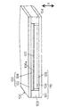
- FIG. 1 is a diagram showing a laminated structure of an all-solid lithium battery 100 according to the present invention.
- FIG. 2 is a flowchart showing an example of a method for manufacturing positive electrode plate 106 constituting all solid lithium battery 100 in FIG.
- a chip-type all-solid lithium battery (hereinafter, also simply referred to as “all-solid battery”) 100 configured in a plate shape is a secondary battery (rechargeable) that can be repeatedly used by charging and discharging. Battery).
- the all solid state battery 100 includes a positive electrode side current collecting layer 101, a negative electrode side current collecting layer 102, exterior materials 103 and 104, a current collecting connection layer 105, a positive electrode plate 106, a solid electrolyte layer 107, and a negative electrode layer 108.
- a positive electrode side current collecting layer 101, a current collecting connection layer 105, a positive electrode plate 106, a solid electrolyte layer 107, a negative electrode layer 108, and a negative electrode side current collecting layer 102 are laminated in order from the positive electrode side. Is arranged.
- the end of the all solid state battery 100 in the plate width direction is sealed with exterior materials 103 and 104.
- the positive electrode 110 is constituted by the positive electrode side current collecting layer 101, the current collecting connection layer 105 and the positive electrode plate 106.
- a negative electrode 120 is constituted by the negative electrode side current collecting layer 102 and the negative electrode layer 108.
- This all-solid-state lithium battery 100 corresponds to the “all-solid-state battery” of the present invention.
- the positive electrode plate 106 is mainly composed of LiCoO 2 having a layered rock salt structure, and is a lithium cobaltate oriented sintered plate in which the (104) plane with respect to the Miller index hkl among the plurality of crystal planes is aligned parallel to the plate surface.
- the positive electrode plate 106 includes Mg, Al, Si, Ca, Ti, V, Cr, Fe, Cu, Zn, Ga, Ge, Sr, Y, Zr, Nb, Mo, Ag, Sn, Sb, Te, Ba.
- the positive electrode plate 106 is a compound containing at least one additional element selected from the group consisting of Ti, Al and Zr, W, Mg, Nb, Ba (hereinafter also referred to as “additive element compound”). ).
- the positive electrode plate 106 here corresponds to the “positive electrode plate for all-solid-state battery” of the present invention.
- the positive electrode plate 106 may be made of a material other than LiCoO 2 .
- the solid electrolyte layer 107 is preferably made of a lithium phosphate oxynitride (LiPON) ceramic material which is one of oxide ceramic materials.
- the thickness of the solid electrolyte layer 107 is not particularly limited, but can be 0.1 to 10 ⁇ m.
- the thickness of the solid electrolyte layer 107 is preferably 1.0 ⁇ m to 6.0 ⁇ m.
- the thickness of the solid electrolyte layer 107 is also preferably 0.5 to 3.0 ⁇ m.
- a sputtering method as a film forming method for depositing the solid electrolyte layer 107 made of a ceramic material on the solid electrolyte layer side surface 106a of the positive electrode plate 106 to form a battery.
- the thickness of the solid electrolyte layer 107 can be adjusted by controlling film formation conditions (for example, film formation time) in this sputtering method.
- LiPON is a group of compounds represented by the composition of Li 2.9 PO 3.3 N 0.46 .
- Li a PO b N c (wherein a is 2 to 4 and b is 3 to 5 , C is 0.1 to 0.9). Therefore, the formation of the LiPON-based solid electrolyte layer by sputtering is performed by using a lithium phosphate sintered body target as a Li source, a P source and an O source, and introducing N 2 as a gas species as an N source.
- the sputtering method is not particularly limited, but the RF magnetron method is preferable. Further, a film forming method such as MOCVD method, sol-gel method, aerosol deposition method, screen printing method, or the like can be used instead of the sputtering method.
- the solid electrolyte layer 107 here corresponds to the “solid electrolyte layer” of the present invention.
- the solid electrolyte layer 107 may be made of an oxide ceramic material other than the LiPON ceramic material.
- the other oxide ceramic materials include at least one selected from the group consisting of garnet ceramic materials, nitride ceramic materials, perovskite ceramic materials, phosphate ceramic materials, and zeolite materials.
- a Li—La—Zr—O-based material specifically, Li 7 La 3 Zr 2 O 12 or the like
- a Li—La—Ta—O-based material can also be used.
- perovskite ceramic materials include Li—La—Ti—O materials (specifically, LiLa 1-x Ti x O 3 (0.04 ⁇ x ⁇ 0.14), etc.).
- Examples of phosphoric acid based ceramic materials include Li—Al—Ti—PO, Li—Al—Ge—PO, and Li—Al—Ti—Si—PO (specifically, Li 1 + x + y Al x Ti 2-x Si y P 3-y O 12 (0 ⁇ x ⁇ 0.4, 0 ⁇ y ⁇ 0.6) and the like.
- the manufacturing method for manufacturing the positive electrode plate 106 having the above-described configuration includes a green sheet manufacturing step S101, a green sheet firing step S102, a lithium cobaltate oriented sintered plate manufacturing step S103, It is included.
- One or more separate processes can be added before and after each of these three processes.
- the surface roughness of the surface of the sintered plate obtained in the step of adjusting the surface roughness of the fired plate obtained in the green sheet firing step S102 or the lithium cobaltate oriented sintered plate production step S103 is obtained. It is preferable to employ a step of adjusting the thickness.
- a polishing process for polishing the surface of a fired plate or a sintered plate, a heat treatment for further firing the fired plate or sintered plate after the polishing process, or a chemical treatment using a corrosive action such as a chemical like etching It is possible to use heat treatment in a state where an additive such as lithium, titanium, or magnesium is added, or to apply lithium cobalt oxide or cobalt oxide particles on a lithium cobaltate or cobalt oxide sintered plate and heat-treat. it can.
- the sheet-like fired body obtained in the green sheet firing step S102 that is, the fired body before lithium is introduced is described as a “fired plate”, and a lithium cobaltate oriented sintered plate production step
- the sheet-like fired body obtained in S103 that is, the fired body after lithium is introduced is described as “sintered plate”.
- both the sheet-like fired body before lithium is introduced and the sheet-like fired body after lithium is introduced can also be referred to as a “fired plate”.
- the green sheet manufacturing process includes a Co raw material (typically Co 3 O 4 (tricobalt tetroxide) particles) and a bismuth oxide (typically Bi 2 O 3 particles) as an alignment accelerator.
- This is a process for producing an unfired sheet-like green sheet containing.
- the green sheet can be obtained by forming a raw material containing Co 3 O 4 particles and Bi 2 O 3 particles into a sheet shape.
- the amount of Bi 2 O 3 particles added is not particularly limited, but is preferably 0.1 to 30% by weight, more preferably 1 to 3 % by weight based on the total amount of Co 3 O 4 particles and Bi 2 O 3 particles. It is 20% by weight, more preferably 3 to 10% by weight.
- the volume-based D50 particle size of the Co 3 O 4 particles is preferably 0.1 to 0.6 ⁇ m.
- the volume-based D50 particle size of Bi 2 O 3 particles is preferably 0.1 to 1.0 ⁇ m, more preferably 0.2 to 0.5 ⁇ m.
- the thickness of the green sheet is 100 ⁇ m or less, preferably 1 to 80 ⁇ m, more preferably 5 to 65 ⁇ m.
- the green sheet is, to Co raw material may be composed of only Co 3 O 4 particles, or in place of all or part of the Co 3 O 4 particles, CoO particles and / or Co (OH) 2 It may contain particles. That is, in the present invention, the Co raw material is not limited to Co 3 O 4 as long as it contains at least Co.
- the (h00) plane for the Miller index hkl is changed to the sheet plane by firing the green sheet in the green sheet firing step S102.
- CoO-based fired intermediates or Co 3 O 4 oriented fired plates can be prepared in parallel with the substrate, and as a result, the same as in the case of using a green sheet in which the Co raw material is composed only of Co 3 O 4 particles, A lithium cobaltate oriented sintered plate having the same performance can be produced in the lithium cobaltate oriented sintered plate production step S103.
- a doctor blade method using a slurry containing raw material particles In producing green sheets, (i) a doctor blade method using a slurry containing raw material particles, (ii) applying a slurry containing a raw material onto a heated drum, and scraping the dried slurry with a scraper (Iii)
- a method such as an extrusion molding method using a clay containing raw material particles can be employed.
- a particularly preferable sheet forming method is a doctor blade method.
- the slurry is applied to a flexible plate (for example, an organic polymer plate such as a PET film), and the applied slurry is dried and solidified to form a molded product, and the molded product and the plate are peeled off.
- a green sheet may be produced.
- inorganic particles When preparing a slurry or clay before molding, inorganic particles may be dispersed in a dispersion medium, and a binder, a plasticizer, or the like may be added as appropriate.
- the slurry is preferably prepared so as to have a viscosity of 500 to 4000 cP, and is preferably degassed under reduced pressure.
- the green sheet does not initially have a orientation (in non-oriented However, orientation occurs at the stage where the Co 3 O 4 particles undergo phase transformation to CoO and grow as the temperature rises during firing (hereinafter referred to as “CoO oriented grain growth”).
- the Co 3 O 4 particles temporarily pass through the sintered intermediate in which the (h00) plane is changed to CoO oriented parallel to the sheet surface. That is, the Co oxide phase transforms from a spinel structure represented by Co 3 O 4 at room temperature to a CoO rock salt structure at 900 ° C. or higher (eg, 920 ° C. or higher).
- Co 3 O 4 is reduced to transform into CoO and the sheet is densified.
- CoO is oxidized to Co 3 O 4 in the process of lowering the temperature of the firing intermediate when the temperature is lowered after firing.
- the orientation firing direction of CoO is inherited by Co 3 O 4 , thereby forming an oriented fired plate composed of a large number of Co 3 O 4 particles oriented so that the (h00) plane is parallel to the sheet surface.
- bismuth oxide typically Bi 2 O 3
- oriented grain growth of CoO is promoted.
- bismuth volatilizes and is removed from the sheet.
- the firing temperature of the green sheet is in the range of 900 to 1350 ° C., preferably 1000 to 1300 ° C., more preferably 1050 to 1300 ° C.
- the time for firing the green sheet at the firing temperature is preferably in the range of 1 to 20 hours, more preferably 2 to 10 hours.
- the temperature lowering rate after firing the green sheet at the firing temperature is preferably in the range of 10 to 200 ° C./hour, more preferably 20 to 100 ° C./hour.
- the green sheet thickness of 100 ⁇ m or less contributes to the CoO grain growth. That is, in a green sheet having a thickness of 100 ⁇ m or less, the amount of material present in the thickness direction is extremely small compared to the in-plane direction (the direction perpendicular to the thickness direction). For this reason, in the initial stage where there are a plurality of grains in the thickness direction, grains grow in random directions. On the other hand, when the grain growth proceeds and the material in the thickness direction is consumed, the grain growth direction is limited to a two-dimensional direction in the sheet surface (hereinafter referred to as a plane direction). This reliably promotes grain growth in the surface direction.
- the green sheet by forming the green sheet as thin as possible (for example, several ⁇ m or less), or by promoting grain growth as much as possible even when the green sheet is relatively thick (for example, about 20 ⁇ m).
- the grain growth in the surface direction can be surely promoted.
- only the particles having the crystal plane with the lowest surface energy in the plane of the green sheet are selectively grown in a flat shape (plate shape) in the plane direction.
- CoO plate-like crystal grains having a large aspect ratio and oriented so that the (h00) plane is parallel to the plate surface of the grains are oriented with the (h00) plane parallel to the sheet plane.
- a calcined intermediate containing is obtained.
- CoO is oxidized to Co 3 O 4 in the course of the firing temperature intermediate decreases, the orientation baking plate comprising a number of Co 3 O 4 particles oriented in parallel with the (h00) face sheet surface It is formed as described above.
- the Co 3 O 4 oriented fired plate made of a large number of Co 3 O 4 particles is an independent plate-like sheet.
- An “independent” sheet refers to a sheet that can be handled as a single unit independently of other supports after firing. That is, the “independent” sheet does not include a sheet fixed to another support (substrate or the like) by firing and integrated with the support (unseparable or difficult to separate). In this way, a self-supporting oriented sintered plate is obtained in which a large number of grains oriented such that the (h00) plane is parallel to the grain plane.
- This self-supporting plate can be a dense Co 3 O 4 oriented fired plate in which a large number of Co 3 O 4 particles as described above are bonded without gaps.
- the lithium cobalt oxide oriented sintered plate production step is a step of firing the Co 3 O 4 oriented fired plate obtained in the green sheet firing step in a lithium atmosphere in which a lithium source coexists. According to this step, lithium (Li) is introduced into the Co 3 O 4 oriented fired plate. The introduction of lithium is preferably performed by reacting a Co 3 O 4 oriented fired plate with a lithium compound.
- Typical lithium compounds as the lithium source include (i) lithium hydroxide, (ii) various lithium salts such as lithium carbonate, lithium nitrate, lithium acetate, lithium chloride, lithium oxalate, and lithium citrate, (iii) Examples include lithium alkoxides such as lithium methoxide and lithium ethoxide, and lithium hydroxide or lithium carbonate is particularly preferably used as the lithium source.
- Co 3 O 4 oriented fired plate and lithium source can coexist as a method of attaching lithium raw material powder to the surface of the Co 3 O 4 oriented fired plate, a solution in which lithium raw material is dissolved, or a slurry in which raw material powder is dispersed.
- Is applied to the surface of the Co 3 O 4 oriented fired plate using a spray or dispenser a method of placing a green sheet containing Li raw material powder on one or both sides of the Co 3 O 4 oriented fired plate, and a Li compound on the surface.
- a method of placing a green sheet containing Li raw material powder on one or both sides of the Co 3 O 4 oriented fired plate, and a Li compound on the surface examples thereof include a method in which a Co 3 O 4 oriented fired plate is placed on a setter that is included, and further sandwiched.
- the conditions for introducing lithium for example, the mixing ratio, the heating rate, the heating temperature, the heating time, the atmosphere, etc. may be appropriately set in consideration of the melting point, decomposition temperature, reactivity, etc. of the material used as the lithium source. There is no particular limitation.
- lithium can be introduced into the Co 3 O 4 particles by applying a predetermined amount of a slurry in which LiOH powder is dispersed on a Co 3 O 4 oriented fired plate and drying it, followed by heating.
- the heating temperature at this time is preferably 600 to 880 ° C., and heating is preferably performed at a temperature within this range for 2 to 20 hours.
- the amount of the lithium compound attached to the Co 3 O 4 oriented fired plate is preferably 1.0 or more in terms of Li / Co ratio, more preferably 1.0 to 1.5. Even when there is too much Li, there is no problem since the excess Li volatilizes and disappears with heating.
- the Co 3 O 4 oriented fired plate may be fired under a load.
- it may be weighted with a porous setter or a setter having a hole (for example, a honeycomb setter).
- a porous setter or a setter having a hole for example, a honeycomb setter.
- the surface of the Co 3 O 4 oriented fired plate is polished before introducing lithium.
- the surface roughness of the Co 3 O 4 oriented fired plate can be controlled by introducing lithium after the polishing treatment.
- the lithium cobalt oxide oriented sintered plate thus obtained (positive electrode plate 106 in FIG. 1) has an orientation such that the (104) plane of LiCoO 2 is parallel to the plate surface. Accordingly, among the plurality of crystal planes, the (104) plane in which lithium ions are satisfactorily entered and exited is oriented parallel to the plane of the oriented sintered plate. For this reason, when this oriented sintered plate is used as a positive electrode active material to form a battery, exposure (contact) of the surface to the electrolyte is increased, and the (003) surface (lithium) on the surface of the particle or plate is increased. The exposure ratio of the surface that is not suitable for ion entry / exit is extremely low.
- the lithium cobaltate oriented sintered plate when used as a positive electrode material for a solid lithium secondary battery, high capacity and high rate characteristics can be achieved simultaneously.
- the orientation of the lithium cobalt oxide oriented sintered plate in the XRD profile when the surface of the sintered plate is irradiated with X-rays, the diffraction intensity by the (003) plane relative to the diffraction intensity (peak height) by the (104) plane It is expressed as a ratio (peak height) I [003] / I [104].
- the thickness of the lithium cobalt oxide oriented sintered plate is preferably 5 to 80 ⁇ m, more preferably 10 to 70 ⁇ m, still more preferably 20 to 60 ⁇ m, and particularly preferably 20 to 50 ⁇ m.
- the size of the lithium cobalt oxide oriented sintered plate is preferably 5 mm ⁇ 5 mm square or more, more preferably 10 mm ⁇ 10 mm to 100 mm ⁇ 100 mm square, and further preferably 10 mm ⁇ 10 mm to 50 mm ⁇ 50 mm square. Is preferably 25 mm 2 or more, more preferably 100 to 10000 mm 2 , and still more preferably 100 to 2500 mm 2 .
- the density of the lithium cobalt oxide oriented sintered plate is preferably 80% by volume or more, more preferably 85% by volume or more and 99.8% by volume or less, more preferably 90% by volume or more and 99.5% by volume or less.
- the “dense density” is typically a value calculated by dividing the density of the lithium cobaltate oriented sintered plate by the theoretical density (known value) of lithium cobaltate.
- the “porosity (volume%)” is an area of pores observed in a predetermined region (for example, 50 ⁇ m in length and width) when the cross-sectional polished surface of the substrate is observed with a scanning electron microscope (SEM).
- the density may be calculated by measuring from the ratio and applying the measured value to the formula of “100 (volume%) ⁇ porosity (volume%)”.
- the density becomes 100% by volume.
- it is completely dense density 100 volume%), cracks are likely to occur inside the positive electrode plate due to expansion and contraction of the positive electrode plate during charge and discharge, and cycle characteristics deteriorate.
- the surface of the lithium cobaltate oriented sintered plate is coated with the additive element compounds (Ti, Al and Zr, W, It is also possible to add a step of coating with a compound containing at least one additional element selected from the group consisting of Mg, Nb, and Ba).
- the coating step with the additive element compound may be a step performed prior to step S103 between step S102 and step S103 in FIG. 2, or may be a step performed after step S103. Good.
- the additive elements (Mg, Al, Si, Ca, Ti, V, Cr, Fe, Cu, Zn, Ga, Ge, Sr, Y, Zr, Nb, Mo, Ag, (Sn, Sb, Te, Ba, Bi, etc.) is added by any one of the above-described steps S101 to S103 and the coating step (typically, step S101 or step S103). Can be done.
- the surface on which the solid electrolyte layer is formed in the lithium cobaltate oriented sintered plate (positive electrode plate) (FIG. 1).
- a polishing process with a polishing paper or a polishing tool may be performed, and a further heat treatment is performed after the polishing process. You may implement.
- the heat treatment is preferably performed at 300 ° C. to 900 ° C. for 1 hour to 10 hours.
- the surface roughness of the lithium cobalt oxide oriented sintered plate can be adjusted by performing heat treatment without polishing treatment or by performing heat treatment after adhering the above-mentioned additive element or the compound containing the lithium raw material.
- the surface roughness of the lithium cobaltate oriented sintered plate can be adjusted by immersing the lithium cobaltate oriented sintered plate in a weak acid such as acetic acid and chemically treating the surface.
- the surface roughness of the lithium cobaltate oriented sintered plate can also be adjusted by applying lithium cobaltate or cobalt oxide particles on the lithium cobaltate or cobalt oxide sintered plate and heat-treating it.
- processes other than the above-mentioned process can also be utilized as a process for adjusting the surface roughness of the lithium cobalt oxide oriented sintered plate.
- a solid is finally obtained.
- the surface roughness of the positive electrode plate on which the electrolyte layer is formed can be adjusted to a desired setting range. When the surface roughness of the positive electrode plate is less than 0.1 ⁇ m, the solid electrolyte layer is easily peeled off from the positive electrode plate due to the volume expansion and contraction of the positive electrode plate during charging and discharging, and the cycle characteristics are deteriorated.
- the surface roughness of the positive electrode plate exceeds 0.7 ⁇ m, local electric field concentration tends to occur in the uneven portion of the surface during the charge / discharge cycle test. Therefore, by adjusting the surface roughness of the positive electrode plate in the range from 0.1 ⁇ m to 0.7 ⁇ m, it is possible to suppress the occurrence of local electric field concentration and to prevent the occurrence of peeling as described above. As a result, by adjusting the surface roughness of the positive electrode plate, it is possible to provide an all solid lithium battery having particularly excellent cycle characteristics. Note that, for the surface roughness of the positive electrode plate, the arithmetic average roughness Ra obtained in accordance with the method described in JIS0601-2001 is used.
- the surface roughness (arithmetic mean roughness) Ra of the positive electrode plate is obtained by scanning a range of 0.15 mm with a 3D laser microscope (OLS4100 manufactured by Olympus) at three different positions on the surface of the positive electrode plate. It can be obtained by arithmetically averaging two measurement results.
- the surface roughness which is one of the parameters for specifying the surface uneven structure of the positive electrode plate, is described.
- the surface unevenness may be used instead of or in addition to the surface roughness as necessary.
- Other parameters that specify the structure eg, specific surface area
- the thickness of the solid electrolyte layer is further adjusted to a range from 1.0 ⁇ m to 6.0 ⁇ m after the surface roughness of the positive electrode plate is adjusted to the set range.
- the thickness of the solid electrolyte layer it is preferable to adjust the thickness of the solid electrolyte layer to a range from 0.5 ⁇ m to 3.0 ⁇ m after adjusting the surface roughness of the positive electrode plate to the set range.
- the thickness of the solid electrolyte layer By setting the thickness of the solid electrolyte layer to 0.5 ⁇ m or more, it is possible to make it difficult for defects to occur in the solid electrolyte layer.
- the thickness of the solid electrolyte layer it is possible to suppress peeling in the solid electrolyte layer and to suppress an increase in resistance of the solid electrolyte layer itself, thereby improving rate characteristics. it can.
- the rate characteristic can be improved even when the thickness of the solid electrolyte layer is limited as in the case where the resistance of the solid electrolyte layer itself is desired to be suppressed. As a result, an all solid lithium battery excellent in both cycle characteristics and rate characteristics can be provided.
- lithium cobaltate (LiCoO 2 ) oriented sintered plates As examples and comparative examples, five types of lithium cobaltate oriented sintered plates were prepared according to the following procedure.
- the viscosity at the time of preparation was measured with a Brookfield LVT viscometer.
- the slurry prepared as described above was formed into a sheet shape on a PET film so that the thickness after drying was 24 ⁇ m by a doctor blade method to obtain a green sheet.
- I [003] / I [104] was 0.3.
- the ratio I [003] / I [104] was 1.6. From this, it was confirmed that a large number of (104) planes of LiCoO 2 exist in parallel to the plate surface, that is, it has a desired orientation suitable for a high-capacity lithium secondary battery.
- Each lithium cobaltate oriented sintered plate (positive electrode plate) is made of a stainless steel current collector plate (positive electrode side collector) with an epoxy-based conductive adhesive in which conductive carbon is dispersed. The positive electrode was produced by fixing to an electrode.
- a film thickness (thickness) of 2 ⁇ m was obtained under the conditions of N 2 which is a gas species in a RF magnetron method with a sputtering apparatus (SPF-430H manufactured by Canon Anelva Co., Ltd.) under a pressure of 0.2 Pa and an output of 0.2 kW.
- Sputtering was performed as follows.
- a LiPON-based solid electrolyte sputtered film having a thickness of 2 ⁇ m was formed on the positive electrode plate.
- the actual film thickness of the solid electrolyte layer was confirmed by cross-sectional SEM observation after the surface of the solid electrolyte layer was chemically polished (CP polishing).
- the surface roughness Ra of the positive electrode plate is less than 0.1 ⁇ m or more than 0.7 ⁇ m, a high-performance all-solid lithium battery desired by the inventor cannot be obtained.
- the capacity retention rate was 98% or more without causing separation of the solid electrolyte layer from the positive electrode plate. It was confirmed that it was maintained at a high level. Therefore, it was confirmed that by adjusting the surface roughness Ra of the positive electrode plate in the range of 0.1 ⁇ m to 0.7 ⁇ m, a high-performance all-solid lithium battery with little capacity reduction can be provided.
- SYMBOLS 100 ... All-solid-state lithium battery (all-solid-state battery), 101 ... Positive electrode side collector electrode, 102 ... Negative electrode side collector electrode, 103,104 ... Exterior material, 105 ... Current collection connection layer, 106 ... Positive electrode plate (lithium cobaltate oriented firing) (Binder plate), 106a ... solid electrolyte layer side surface, 107 ... solid electrolyte layer, 108 ... negative electrode layer, 110 ... positive electrode, 120 ... negative electrode
Landscapes
- Chemical & Material Sciences (AREA)
- Chemical Kinetics & Catalysis (AREA)
- Electrochemistry (AREA)
- General Chemical & Material Sciences (AREA)
- Engineering & Computer Science (AREA)
- Manufacturing & Machinery (AREA)
- Materials Engineering (AREA)
- Inorganic Chemistry (AREA)
- General Physics & Mathematics (AREA)
- Condensed Matter Physics & Semiconductors (AREA)
- Physics & Mathematics (AREA)
- Battery Electrode And Active Subsutance (AREA)
- Secondary Cells (AREA)
- Composite Materials (AREA)
- Ceramic Engineering (AREA)
Abstract
本発明にかかる全固体電池用正極板(106)は、リン酸リチウムオキシナイトライド系セラミックス材料からなる固体電解質層(107)を含む全固体電池(100)の正極を構成するものであり、固体電解質層(107)が形成される固体電解質層側表面(106a)の表面粗さが0.1μmから0.7μmまでの範囲にある。
Description
本発明は、全固体電池の正極を構成する全固体電池用正極板に関する。
従来、全固体電池の正極を構成する正極板(正極活物質)としてリチウム酸化物を用いたものが知られており、この種の正極板の一例が特許文献1に開示されている。この正極板は、Co3O4と配向促進剤とを含有するグリーンシートを焼成し、その焼成体にリチウムイオンが導入されることによって得られる配向焼結板である。この配向焼結板の表面に固体電解質層が形成されることによって全固体電池(全固体リチウム電池)が形成される。
ところで、本発明者らは、この種の全固体電池の開発段階において、正極板のうち固体電解質層が形成される固体電解質層側表面の表面凹凸構造(表面凹凸の度合い)が電池性能に影響を及ぼすという知見を得た。具体的に説明すると、正極板の表面凹凸が大き過ぎると、充放電サイクル試験時にこの凹凸部分に局部的な電界集中が生じ易くなる。例えば、
上記の特許文献1に開示の全固体電池の正極板は、その表面粗さ(表面凹凸構造を示す指標の1つである表面粗さ)が0.8μmを上回る程度のレベルにあり、凹凸部分での局部的な電界集中の発生が懸念される。一方で、正極板の表面凹凸が小さ過ぎると、充放電時に体積膨張及び体積収縮を生じた場合に、正極板から固体電解質層が剥離し易くなり、その結果、全固体電池の所望のサイクル特性が得られなくなる。本発明者らは、全固体電池の構成要素が全固体電池の電池性能(サイクル特性、レート特性など)に及ぼす影響について鋭意検討の結果、少なくとも正極板の表面凹凸構造の適正化を図ることによって、前述のような局部的な電界集中の発生を抑え、且つ前述のような剥離の発生を防止することができ、以って電池性能に優れた全固体電池を構築することが可能であるという知見を得た。
上記の特許文献1に開示の全固体電池の正極板は、その表面粗さ(表面凹凸構造を示す指標の1つである表面粗さ)が0.8μmを上回る程度のレベルにあり、凹凸部分での局部的な電界集中の発生が懸念される。一方で、正極板の表面凹凸が小さ過ぎると、充放電時に体積膨張及び体積収縮を生じた場合に、正極板から固体電解質層が剥離し易くなり、その結果、全固体電池の所望のサイクル特性が得られなくなる。本発明者らは、全固体電池の構成要素が全固体電池の電池性能(サイクル特性、レート特性など)に及ぼす影響について鋭意検討の結果、少なくとも正極板の表面凹凸構造の適正化を図ることによって、前述のような局部的な電界集中の発生を抑え、且つ前述のような剥離の発生を防止することができ、以って電池性能に優れた全固体電池を構築することが可能であるという知見を得た。
本発明は、上記の点に鑑みてなされたものである。即ち、本発明の目的の1つは、電池性能に優れた全固体電池を提供することである。
(課題を解決するための手段)
上記目的を達成するため、本発明に係る全固体電池用正極板(以下、単に「正極板」ともいう)は、酸化物系セラミックス材料からなる固体電解質層を含む全固体電池の正極を構成するものであり、固体電解質層が形成される固体電解質層側表面(被着面)の表面粗さが0.1μmから0.7μmまでの範囲にある。本発明者らは、全固体電池の評価試験を繰り返し実施した結果、少なくとも正極板の表面粗さを0.1μmから0.7μmまでの範囲に調整した場合は、そうでない場合に比べて、全固体電池の電池性能を高いレベルに維持することができることを見出した。即ち、正極板の表面粗さが0.1μmを下回ると、充放電時の正極板の体積膨張及び体積収縮によって正極板から固体電解質層が剥離し易くなりサイクル特性が低下する。また、正極板の表面粗さが0.7μmを上回ると、充放電サイクル試験時に表面の凹凸部分に局部的な電界集中が生じ易くなる。従って、正極の表面粗さを0.1μmから0.7μmまでの範囲に調整することによって、特にサイクル特性に優れた全固体電池を構築することが可能になる。
上記目的を達成するため、本発明に係る全固体電池用正極板(以下、単に「正極板」ともいう)は、酸化物系セラミックス材料からなる固体電解質層を含む全固体電池の正極を構成するものであり、固体電解質層が形成される固体電解質層側表面(被着面)の表面粗さが0.1μmから0.7μmまでの範囲にある。本発明者らは、全固体電池の評価試験を繰り返し実施した結果、少なくとも正極板の表面粗さを0.1μmから0.7μmまでの範囲に調整した場合は、そうでない場合に比べて、全固体電池の電池性能を高いレベルに維持することができることを見出した。即ち、正極板の表面粗さが0.1μmを下回ると、充放電時の正極板の体積膨張及び体積収縮によって正極板から固体電解質層が剥離し易くなりサイクル特性が低下する。また、正極板の表面粗さが0.7μmを上回ると、充放電サイクル試験時に表面の凹凸部分に局部的な電界集中が生じ易くなる。従って、正極の表面粗さを0.1μmから0.7μmまでの範囲に調整することによって、特にサイクル特性に優れた全固体電池を構築することが可能になる。
また、上記構成の固体電解質層側表面に形成される固体電解質層については、その厚さが1.0μmから6.0μmまでの範囲にあるのが好ましい。これによって、固体電解質層の成膜条件によって膜応力を調整することができるため、固体電解質層の剥離を抑制して局部的な短絡を低減させることができる。従って、表面粗さが0.1μmから0.7μmまでの範囲に調整された正極板に対して、厚さが1.0μmから6.0μmまでの範囲に調整された固体電解質層を割り当てることによって、特にサイクル特性及びレート特性の双方に優れた全固体電池を構築することが可能になる。
また、上記構成の固体電解質層側表面に形成される固体電解質層については、その厚さが0.5μmから3.0μmまでの範囲にあるのが好ましい。固体電解質層の厚さを0.5μmから3.0μmまでの範囲に調整した場合は、そうでない場合に比べて、全固体電池の電池性能をより高いレベルに維持することができる。即ち、固体電解質層の厚さを0.5μm以上とすることによって、固体電解質層に欠陥が生じ難くすることができる。また、固体電解質層の厚さを3.0μm以下とすることによって、固体電解質層内での剥離を抑制するとともに固体電解質層自体の抵抗が増えることを抑制できるため、レート特性を向上させることができる。従って、表面粗さが0.1μmから0.7μmまでの範囲に調整された正極板に対して、厚さが0.5μmから3.0μmまでの範囲に調整された固体電解質層を割り当てることによって、特にサイクル特性及びレート特性の双方に特に優れた全固体電池を構築することが可能になる。
また、上記構成の固体電解質層側表面に形成される固体電解質層については、その厚さが0.5μmから3.0μmまでの範囲にあるのが好ましい。固体電解質層の厚さを0.5μmから3.0μmまでの範囲に調整した場合は、そうでない場合に比べて、全固体電池の電池性能をより高いレベルに維持することができる。即ち、固体電解質層の厚さを0.5μm以上とすることによって、固体電解質層に欠陥が生じ難くすることができる。また、固体電解質層の厚さを3.0μm以下とすることによって、固体電解質層内での剥離を抑制するとともに固体電解質層自体の抵抗が増えることを抑制できるため、レート特性を向上させることができる。従って、表面粗さが0.1μmから0.7μmまでの範囲に調整された正極板に対して、厚さが0.5μmから3.0μmまでの範囲に調整された固体電解質層を割り当てることによって、特にサイクル特性及びレート特性の双方に特に優れた全固体電池を構築することが可能になる。
上記構成の全固体電池用正極板では、その厚さが10μmから60μmまでの範囲にあるのが好ましい。これにより、全固体電池に適した厚さの正極板を提供できる。
上記構成の全固体電池用正極板は、コバルト酸リチウムを含み、且つ固体電解質層が酸化物系セラミックス材料のうちの1つであるリン酸リチウムオキシナイトライド系セラミックス材料からなるのが好ましい。これにより、全固体リチウム電池に適した正極板を提供できる。
以上のように、本発明によれば、少なくとも正極板のうち固体電解質層が形成される固体電解質層側表面の表面凹凸構造を調整することによって、電池性能に優れた全固体電池を提供することが可能になった。
以下、本発明の実施形態について図面を参照しながら説明する。
(全固体リチウム電池)
図1に示されるように、板片状に構成されたチップ型の全固体リチウム電池(以下、単に「全固体電池」ともいう)100は、充放電によって繰り返し使用可能な二次電池(充電式電池)である。この全固体電池100は、正極側集電層101、負極側集電層102、外装材103,104、集電接続層105、正極板106、固体電解質層107及び負極層108を含む。この全固体電池100の板厚方向Xについて正極側から順に、正極側集電層101、集電接続層105、正極板106、固体電解質層107、負極層108、負極側集電層102が積層配置されている。この全固体電池100の板幅方向の端部は外装材103,104によって封止されている。正極側集電層101、集電接続層105及び正極板106によって正極110が構成される。負極側集電層102及び負極層108によって負極120が構成される。この全固体リチウム電池100が本発明の「全固体電池」に相当する。
図1に示されるように、板片状に構成されたチップ型の全固体リチウム電池(以下、単に「全固体電池」ともいう)100は、充放電によって繰り返し使用可能な二次電池(充電式電池)である。この全固体電池100は、正極側集電層101、負極側集電層102、外装材103,104、集電接続層105、正極板106、固体電解質層107及び負極層108を含む。この全固体電池100の板厚方向Xについて正極側から順に、正極側集電層101、集電接続層105、正極板106、固体電解質層107、負極層108、負極側集電層102が積層配置されている。この全固体電池100の板幅方向の端部は外装材103,104によって封止されている。正極側集電層101、集電接続層105及び正極板106によって正極110が構成される。負極側集電層102及び負極層108によって負極120が構成される。この全固体リチウム電池100が本発明の「全固体電池」に相当する。
(正極板)
正極板106は、主として層状岩塩構造を有するLiCoO2からなり、特に複数の結晶面のうちミラー指数hklについての(104)面が板面と平行に配向されたコバルト酸リチウム配向焼結板である。この正極板106には、Mg,Al,Si,Ca,Ti,V,Cr,Fe,Cu,Zn,Ga,Ge,Sr,Y,Zr,Nb,Mo,Ag,Sn,Sb,Te,Ba,Bi等の元素(以下、「添加元素」ともいう)が1種以上更にドーピング又はそれに準ずる形態(例えば結晶粒子の表層への部分的な固溶、又は偏析)で微量添加されていてもよい。また、この正極板106の表面は、Ti,Al及びZr,W,Mg,Nb,Baからなる群から選択される少なくとも1種以上の添加元素を含む化合物(以下、「添加元素化合物」ともいう)で被覆され得る。ここでいう正極板106が本発明の「全固体電池用正極板」に相当する。
正極板106は、主として層状岩塩構造を有するLiCoO2からなり、特に複数の結晶面のうちミラー指数hklについての(104)面が板面と平行に配向されたコバルト酸リチウム配向焼結板である。この正極板106には、Mg,Al,Si,Ca,Ti,V,Cr,Fe,Cu,Zn,Ga,Ge,Sr,Y,Zr,Nb,Mo,Ag,Sn,Sb,Te,Ba,Bi等の元素(以下、「添加元素」ともいう)が1種以上更にドーピング又はそれに準ずる形態(例えば結晶粒子の表層への部分的な固溶、又は偏析)で微量添加されていてもよい。また、この正極板106の表面は、Ti,Al及びZr,W,Mg,Nb,Baからなる群から選択される少なくとも1種以上の添加元素を含む化合物(以下、「添加元素化合物」ともいう)で被覆され得る。ここでいう正極板106が本発明の「全固体電池用正極板」に相当する。
正極板106は、LiCoO2以外の他の材料からなるものであってもよい。他の材料として、例えば、Lip(Nix,Coy,Mnz)O2(式中、0.9≦p≦1.3、0<x<0.8、0<y<1、0≦z≦0.7、x+y+z=1(好ましくは0.95≦p≦1.1、0.1≦x<0.7、0.1≦y<0.9、0≦z≦0.6、x+y+z=1)又はLip(Nix,Coy,Alz)O2(式中、0.9≦p≦1.3、0.6<x<0.9、0.1<y≦0.3、0≦z≦0.2、x+y+z=1(好ましくは0.95≦p≦1.1、0.7<x<0.9、0.1<y≦0.25、0≦z≦0.1、x+y+z=1))で表される基本組成を有する材料を用いることができる。上記の基本組成は、層状岩塩構造を有するリチウム遷移金属酸化物のうちニッケル及びコバルトを含む組成である。そのような組成を有する材料の典型例として、ニッケル・コバルト酸リチウム、コバルト・ニッケル・マンガン酸リチウム、ニッケル・コバルト・アルミニウム酸リチウム等が挙げられる。
(固体電解質層)
固体電解質層107は、酸化物系セラミックス材料の1つであるリン酸リチウムオキシナイトライド(LiPON)系セラミックス材料からなるのが好ましい。この固体電解質層107の厚さは特に制限されないが、0.1~10μmとすることができる。固体電解質層107の厚さは、1.0μmから6.0μmであることが好ましい。これによって、固体電解質層107の成膜条件によって膜応力を調整することができるため、固体電解質層107の剥離を抑制して局部的な短絡を低減させることができる。また、固体電解質層107の厚さは、0.5~3.0μmであることも好ましい。これによって、固体電解質層107における欠陥、剥離及び抵抗を抑制できるため、レート特性を向上させることができる。正極板106のうち固体電解質層側表面106aにこのセラミックス材料からなる固体電解質層107を被着させて電池化する成膜法としてスパッタリング法を用いるのが好ましい。典型的には、このスパッタリング法での成膜条件(例えば、成膜時間)を制御することによって、固体電解質層107の厚さを調整することができる。正極板106は、表面にLiPONからなる固体電解質層をスパッタリング法により形成して電池化した場合であっても電池性能の不具合を生じにくい。LiPONは、Li2.9PO3.3N0.46の組成によって代表されるような化合物群であり、例えばLiaPObNc(式中、aは2~4、bは3~5、cは0.1~0.9である)で表される化合物群である。従って、スパッタリングによるLiPON系固体電解質層の形成は、Li源、P源及びO源としてリン酸リチウム焼結体ターゲットを用いて、N源としてのガス種としてN2を導入することにより公知の条件に従って行えばよい。スパッタリング法は特に限定されないが、RFマグネトロン方式が好ましい。また、スパッタリング法に代えて、MOCVD法、ゾルゲル法、エアロゾルデポジション法、スクリーン印刷法、などの成膜法を用いることもできる。ここでいう固体電解質層107が本発明の「固体電解質層」に相当する。
固体電解質層107は、酸化物系セラミックス材料の1つであるリン酸リチウムオキシナイトライド(LiPON)系セラミックス材料からなるのが好ましい。この固体電解質層107の厚さは特に制限されないが、0.1~10μmとすることができる。固体電解質層107の厚さは、1.0μmから6.0μmであることが好ましい。これによって、固体電解質層107の成膜条件によって膜応力を調整することができるため、固体電解質層107の剥離を抑制して局部的な短絡を低減させることができる。また、固体電解質層107の厚さは、0.5~3.0μmであることも好ましい。これによって、固体電解質層107における欠陥、剥離及び抵抗を抑制できるため、レート特性を向上させることができる。正極板106のうち固体電解質層側表面106aにこのセラミックス材料からなる固体電解質層107を被着させて電池化する成膜法としてスパッタリング法を用いるのが好ましい。典型的には、このスパッタリング法での成膜条件(例えば、成膜時間)を制御することによって、固体電解質層107の厚さを調整することができる。正極板106は、表面にLiPONからなる固体電解質層をスパッタリング法により形成して電池化した場合であっても電池性能の不具合を生じにくい。LiPONは、Li2.9PO3.3N0.46の組成によって代表されるような化合物群であり、例えばLiaPObNc(式中、aは2~4、bは3~5、cは0.1~0.9である)で表される化合物群である。従って、スパッタリングによるLiPON系固体電解質層の形成は、Li源、P源及びO源としてリン酸リチウム焼結体ターゲットを用いて、N源としてのガス種としてN2を導入することにより公知の条件に従って行えばよい。スパッタリング法は特に限定されないが、RFマグネトロン方式が好ましい。また、スパッタリング法に代えて、MOCVD法、ゾルゲル法、エアロゾルデポジション法、スクリーン印刷法、などの成膜法を用いることもできる。ここでいう固体電解質層107が本発明の「固体電解質層」に相当する。
固体電解質層107は、LiPON系セラミックス材料以外のその他の酸化物系セラミックス材料によって構成されてもよい。その他の酸化物系セラミックス材料としては、ガーネット系セラミックス材料、窒化物系セラミックス材料、ペロブスカイト系セラミックス材料、及びリン酸系セラミックス材料、ゼオライト系材料からなる群から選択される少なくとも一種が挙げられる。ガーネット系セラミックス材料の例としては、Li-La-Zr-O系材料(具体的には、Li7La3Zr2O12など)、Li-La-Ta-O系材料も用いることができる。ペロブスカイト系セラミックス材料の例としては、Li-La-Ti-O系材料(具体的には、LiLa1-xTixO3(0.04≦x≦0.14)など)が挙げられる。リン酸系セラミックス材料の例としては、Li-Al-Ti-P-O,Li-Al-Ge-P-O、及びLi-Al-Ti-Si-P-O(具体的には、Li1+x+yAlxTi2-xSiyP3-yO12(0≦x≦0.4、0<y≦0.6)など)が挙げられる。
(正極板の製造方法)
図2に示されるように、上記構成の正極板106を製造するための製造方法には、グリーンシート作製工程S101と、グリーンシート焼成工程S102と、コバルト酸リチウム配向焼結板作製工程S103と、が含まれている。これら3つの各工程の前後に1又は複数の別工程を追加することができる。この別工程として、グリーンシート焼成工程S102で得られた焼成板の表面の表面粗さを調整する工程や、コバルト酸リチウム配向焼結板作製工程S103で得られた焼結板の表面の表面粗さを調整する工程を採用するのが好ましい。これらの工程では、焼成板や焼結板の表面を研磨する研磨処理、研磨処理後の焼成板又は焼結板を更に焼成する熱処理、エッチングのように化学薬品などの腐食作用を利用した化学処理、リチウムやチタン、マグネシウムなどの添加剤を加えた状態での熱処理、コバルト酸リチウムもしくは酸化コバルト焼結板の上にコバルト酸リチウムもしくは酸化コバルトの粒子を塗布し、熱処理することなどを用いることができる。尚、本明細書では、グリーンシート焼成工程S102で得られるシート状の焼成体、即ち、リチウムが導入される前の焼成体を「焼成板」として記載し、コバルト酸リチウム配向焼結板作製工程S103で得られるシート状の焼成体、即ち、リチウムが導入された後の焼成体を「焼結板」として記載している。また、リチウムが導入される前のシート状の焼成体、及びリチウムが導入された後のシート状の焼成体のいずれも「焼成板」と称呼することもできる。
図2に示されるように、上記構成の正極板106を製造するための製造方法には、グリーンシート作製工程S101と、グリーンシート焼成工程S102と、コバルト酸リチウム配向焼結板作製工程S103と、が含まれている。これら3つの各工程の前後に1又は複数の別工程を追加することができる。この別工程として、グリーンシート焼成工程S102で得られた焼成板の表面の表面粗さを調整する工程や、コバルト酸リチウム配向焼結板作製工程S103で得られた焼結板の表面の表面粗さを調整する工程を採用するのが好ましい。これらの工程では、焼成板や焼結板の表面を研磨する研磨処理、研磨処理後の焼成板又は焼結板を更に焼成する熱処理、エッチングのように化学薬品などの腐食作用を利用した化学処理、リチウムやチタン、マグネシウムなどの添加剤を加えた状態での熱処理、コバルト酸リチウムもしくは酸化コバルト焼結板の上にコバルト酸リチウムもしくは酸化コバルトの粒子を塗布し、熱処理することなどを用いることができる。尚、本明細書では、グリーンシート焼成工程S102で得られるシート状の焼成体、即ち、リチウムが導入される前の焼成体を「焼成板」として記載し、コバルト酸リチウム配向焼結板作製工程S103で得られるシート状の焼成体、即ち、リチウムが導入された後の焼成体を「焼結板」として記載している。また、リチウムが導入される前のシート状の焼成体、及びリチウムが導入された後のシート状の焼成体のいずれも「焼成板」と称呼することもできる。
(グリーンシート作製工程)
グリーンシート作製工程は、Co原料(典型的には、Co3O4(四酸化三コバルト)粒子)と、その配向促進剤としてのビスマス酸化物(典型的には、Bi2O3粒子)とを含む未焼成のシート状のグリーンシートを作製するための工程である。この工程によれば、典型的にはCo3O4粒子及びBi2O3粒子を含む原料をシート状に成形することによって、このグリーンシートを得ることができる。Bi2O3粒子の添加量は特に限定されないが、Co3O4粒子及びBi2O3粒子の全体量に対して、0.1~30重量%とするのが好ましく、より好ましくは1~20重量%、さらに好ましくは3~10重量%である。Co3O4粒子の体積基準D50粒径は、0.1~0.6μmであるのが好ましい。Bi2O3粒子の体積基準D50粒径は、0.1~1.0μmであるのが好ましく、より好ましくは0.2~0.5μmである。グリーンシートの厚さは100μm以下であり、好ましくは1~80μm、より好ましくは5~65μmである。
グリーンシート作製工程は、Co原料(典型的には、Co3O4(四酸化三コバルト)粒子)と、その配向促進剤としてのビスマス酸化物(典型的には、Bi2O3粒子)とを含む未焼成のシート状のグリーンシートを作製するための工程である。この工程によれば、典型的にはCo3O4粒子及びBi2O3粒子を含む原料をシート状に成形することによって、このグリーンシートを得ることができる。Bi2O3粒子の添加量は特に限定されないが、Co3O4粒子及びBi2O3粒子の全体量に対して、0.1~30重量%とするのが好ましく、より好ましくは1~20重量%、さらに好ましくは3~10重量%である。Co3O4粒子の体積基準D50粒径は、0.1~0.6μmであるのが好ましい。Bi2O3粒子の体積基準D50粒径は、0.1~1.0μmであるのが好ましく、より好ましくは0.2~0.5μmである。グリーンシートの厚さは100μm以下であり、好ましくは1~80μm、より好ましくは5~65μmである。
尚、グリーンシートは、Co原料がCo3O4粒子のみからなるものであってもよいし、或いはCo3O4粒子の全部又は一部に代えて、CoO粒子及び/又はCo(OH)2粒子を含有するものであってもよい。即ち、本発明では、Co原料は少なくともCoを含むものであればCo3O4のみに限定されるものではない。このようにCoO粒子及び/又はCo(OH)2粒子を含有するグリーンシートの場合においても、グリーンシート焼成工程S102での当該グリーンシートの焼成によって、ミラー指数hklについての(h00)面をシート面と平行に配向したCoO系焼成中間体ないしCo3O4配向焼成板を作製することができ、その結果、Co原料がCo3O4粒子のみからなるグリーンシートを用いる場合と同様に、その後のコバルト酸リチウム配向焼結板作製工程S103で同様の性能を有するコバルト酸リチウム配向焼結板を製造することができる。
グリーンシートの作製においては、(i)原料粒子を含むスラリーを用いたドクターブレード法、(ii)熱したドラム上へ原料を含むスラリーを塗布し、乾燥させたものをスクレイパーで掻き取る、ドラムドライヤーを用いた手法、(iii)原料粒子を含む坏土を用いた押出成形法等の方法を採用することができる。特に好ましいシート形成方法はドクターブレード法である。このドクターブレード法を用いる場合、可撓性を有する板(例えばPETフィルム等の有機ポリマー板)にスラリーを塗布し、塗布したスラリーを乾燥固化して成形体とし、この成形体と板とを剥離することにより、グリーンシートを作製すればよい。成形前にスラリーや坏土を調製するときには、無機粒子を分散媒に分散させ、バインダーや可塑剤等を適宜加えてもよい。また、スラリーは、粘度が500~4000cPとなるように調製するのが好ましく、減圧下で脱泡するのが好ましい。
(グリーンシート焼成工程)
グリーンシート焼成工程は、グリーンシート作製工程で得られたグリーンシートを、所定の焼成温度(900~1350℃)で焼成する工程である。この工程によれば、ミラー指数hklについての(h00)面(hは任意の整数、例えばh=2)がシート面と平行となるような配向性を有するCo3O4配向焼成板(セラミックシート)を作製することができる。
グリーンシート焼成工程は、グリーンシート作製工程で得られたグリーンシートを、所定の焼成温度(900~1350℃)で焼成する工程である。この工程によれば、ミラー指数hklについての(h00)面(hは任意の整数、例えばh=2)がシート面と平行となるような配向性を有するCo3O4配向焼成板(セラミックシート)を作製することができる。
Co原料としてCo3O4粒子を含むグリーンシートの場合、焼成前のCo3O4粒子は等方的な形態を有するため、当該グリーンシートは当初は配向性を有していない(無配向である)が、焼成の昇温時にCo3O4粒子がCoOに相変態して粒成長する段階で配向が生じる(以下、「CoOの配向粒成長」という)。その際、Co3O4粒子が、(h00)面をシート面と平行に配向したCoOに変化した焼成中間体を一時的に経ることとなる。即ち、Coの酸化物は、900℃以上(例えば920℃以上)では、室温におけるCo3O4で表されるスピネル構造からCoOの岩塩構造に相変態する。この焼成によりCo3O4が還元されてCoOに相変態するとともにシートが緻密化される。そして、焼成後の降温時に焼成中間体の温度が下がる過程でCoOがCo3O4に酸化される。その際、CoOの配向方位がCo3O4に引き継がれることで、(h00)面がシート面と平行となるように配向された多数のCo3O4粒子からなる配向焼成板が形成される。特に、ビスマス酸化物(典型的にはBi2O3)の共存下ではCoOの配向粒成長が促進される。この焼成時にビスマスは揮発してシートから除去される。
このグリーンシート焼成工程において、グリーンシートの焼成温度は900~1350℃の範囲内の温度であり、好ましくは1000~1300℃、より好ましくは1050~1300℃である。グリーンシートを上記焼成温度で焼成する時間は1~20時間の範囲内の時間であるのが好ましく、より好ましくは2~10時間である。また、グリーンシートを上記焼成温度で焼成した後の降温速度は、好ましくは10~200℃/時間の範囲内の速度であり、より好ましくは20~100℃/時間である。
CoOの配向粒成長には、100μm以下というグリーンシートの厚さが寄与している。すなわち、厚さ100μm以下のグリーンシートにおいては、シート面内方向(厚さ方向と直交する方向)に比べて、厚さ方向に存在する材料の量が極めて少ない。このため、厚さ方向に複数個の粒子がある初期段階には、ランダムな方向に粒成長する。一方、粒成長が進行して厚さ方向の材料が消費されると、粒成長方向はシート面内の二次元方向(以下、面方向という)に制限されることになる。これにより、面方向への粒成長が確実に促進される。特に、グリーンシートを可能な限り薄く形成したり(例えば数μm以下)、あるいはグリーンシートが比較的厚め(例えば20μm程度)の場合であっても粒成長を可能な限り大きく促進したりすることで、面方向への粒成長を確実に促進させることができる。いずれにしても、焼成の際、表面エネルギーの最も低い結晶面をグリーンシートの面内に持つ粒子のみが選択的に面方向へ扁平状(板状)に粒成長することになる。その結果、グリーンシートの焼成により、アスペクト比が大きく、(h00)面が粒子の板面と平行となるように配向したCoO板状結晶粒子を、その(h00)面をシート面と平行に配向して含む焼成中間体が得られる。その後、焼成中間体の温度が下がる過程でCoOがCo3O4に酸化され、(h00)面がシート面と平行となるように配向された多数のCo3O4粒子からなる配向焼成板が形成されるのは、前述の通りである。
多数のCo3O4粒子からなるCo3O4配向焼成板は、独立した板状のシートである。「独立した」シートとは、焼成後に他の支持体から独立して単体で取り扱い可能なシートのことをいう。即ち、「独立した」シートには、焼成により他の支持体(基板等)に固着されて当該支持体と一体化された(分離不能あるいは分離困難となった)ものは含まれない。こうして(h00)面が粒子の板面と平行となるように配向した多数の粒子が結合した自立した配向焼結板が得られる。この自立板は、上述のような多数のCo3O4粒子が隙間なく結合した、緻密なCo3O4配向焼成板となり得る。
(コバルト酸リチウム配向焼結板作製工程)
コバルト酸リチウム配向焼結板作製工程は、グリーンシート焼成工程で得られたCo3O4配向焼成板をリチウム源が共存するリチウム雰囲気下で焼成する工程である。この工程によれば、Co3O4配向焼成板にリチウム(Li)が導入される。リチウムの導入は、Co3O4配向焼成板をリチウム化合物と反応させることにより行われるのが好ましい。リチウム源であるリチウム化合物として典型的には、(i)水酸化リチウム、(ii)炭酸リチウム、硝酸リチウム、酢酸リチウム、塩化リチウム、シュウ酸リチウム、クエン酸リチウム等の各種リチウム塩、(iii)リチウムメトキシド、リチウムエトキシド等の各種リチウムアルコキシド等が挙げられ、特に好ましくは水酸化リチウム若しくは炭酸リチウムをリチウム源とする。Co3O4配向焼成板とリチウム源を共存させる方法としては、リチウム原料粉末をCo3O4配向焼成板の板面に付着させる方法や、リチウム原料が溶解した溶液や原料粉末が分散したスラリーをスプレーやディスペンサなどによりCo3O4配向焼成板の板面に塗布する方法、Li原料粉末を含むグリーンシートをCo3O4配向焼成板の片面若しくは両面に配置する方法、表面にLi化合物を含むセッターにCo3O4配向焼成板を載せる、さらには挟む方法などが挙げられる。リチウムを導入する際の条件、例えば、混合比、昇温速度、加熱温度、加熱時間、雰囲気等は、リチウム源として用いる材料の融点や分解温度、反応性等を考慮して適宜設定すればよく、特に限定されない。例えば、Co3O4配向焼成板に、LiOH粉末の分散したスラリーを所定量塗布して乾燥させた後、加熱することにより、Co3O4粒子にリチウムを導入することができる。このときの加熱温度は600~880℃が好ましく、この範囲内の温度で2~20時間加熱を行うのが好ましい。また、Co3O4配向焼成板に付着させるリチウム化合物の量はLi/Co比で1.0以上とするのが好ましく、より好ましくは1.0~1.5である。Liが多すぎる場合であっても余剰分のLiは加熱に伴い揮発して消失するため問題は無い。コバルト酸リチウム配向焼結板の平坦性を上げる(例えば、板面の凹凸の度合いを小さく抑える)ために、Co3O4配向焼成板を加重をかけた状態で焼成してもよい。合成に必要な酸素をCo3O4配向焼成板の板面に十分に供給するため、多孔質のセッターや、穴の開いたセッター(例えばハニカム状のセッター)で加重してもよい。コバルト酸リチウム配向焼結板が比較的厚い場合(例えば30μm以上)、付着させるLi原料が嵩高くなり、加熱中に溶融したLi原料の一部が、合成に使われずに流れ出してしまい、合成不良になりやすい。こういう場合、Li原料を付着させ、熱処理する工程(即ち、Liを導入する工程)を繰り返しても良い。
コバルト酸リチウム配向焼結板作製工程は、グリーンシート焼成工程で得られたCo3O4配向焼成板をリチウム源が共存するリチウム雰囲気下で焼成する工程である。この工程によれば、Co3O4配向焼成板にリチウム(Li)が導入される。リチウムの導入は、Co3O4配向焼成板をリチウム化合物と反応させることにより行われるのが好ましい。リチウム源であるリチウム化合物として典型的には、(i)水酸化リチウム、(ii)炭酸リチウム、硝酸リチウム、酢酸リチウム、塩化リチウム、シュウ酸リチウム、クエン酸リチウム等の各種リチウム塩、(iii)リチウムメトキシド、リチウムエトキシド等の各種リチウムアルコキシド等が挙げられ、特に好ましくは水酸化リチウム若しくは炭酸リチウムをリチウム源とする。Co3O4配向焼成板とリチウム源を共存させる方法としては、リチウム原料粉末をCo3O4配向焼成板の板面に付着させる方法や、リチウム原料が溶解した溶液や原料粉末が分散したスラリーをスプレーやディスペンサなどによりCo3O4配向焼成板の板面に塗布する方法、Li原料粉末を含むグリーンシートをCo3O4配向焼成板の片面若しくは両面に配置する方法、表面にLi化合物を含むセッターにCo3O4配向焼成板を載せる、さらには挟む方法などが挙げられる。リチウムを導入する際の条件、例えば、混合比、昇温速度、加熱温度、加熱時間、雰囲気等は、リチウム源として用いる材料の融点や分解温度、反応性等を考慮して適宜設定すればよく、特に限定されない。例えば、Co3O4配向焼成板に、LiOH粉末の分散したスラリーを所定量塗布して乾燥させた後、加熱することにより、Co3O4粒子にリチウムを導入することができる。このときの加熱温度は600~880℃が好ましく、この範囲内の温度で2~20時間加熱を行うのが好ましい。また、Co3O4配向焼成板に付着させるリチウム化合物の量はLi/Co比で1.0以上とするのが好ましく、より好ましくは1.0~1.5である。Liが多すぎる場合であっても余剰分のLiは加熱に伴い揮発して消失するため問題は無い。コバルト酸リチウム配向焼結板の平坦性を上げる(例えば、板面の凹凸の度合いを小さく抑える)ために、Co3O4配向焼成板を加重をかけた状態で焼成してもよい。合成に必要な酸素をCo3O4配向焼成板の板面に十分に供給するため、多孔質のセッターや、穴の開いたセッター(例えばハニカム状のセッター)で加重してもよい。コバルト酸リチウム配向焼結板が比較的厚い場合(例えば30μm以上)、付着させるLi原料が嵩高くなり、加熱中に溶融したLi原料の一部が、合成に使われずに流れ出してしまい、合成不良になりやすい。こういう場合、Li原料を付着させ、熱処理する工程(即ち、Liを導入する工程)を繰り返しても良い。
コバルト酸リチウム配向焼結板の前駆体であるCo3O4配向焼成板の表面粗さを調整する工程を用いる場合、リチウム導入前にCo3O4配向焼成板の表面を研磨処理するのが好ましい。この場合、研磨処理後にリチウム導入を行うことでCo3O4配向焼成板の表面粗さを制御することができる。
こうして得られるコバルト酸リチウム配向焼結板(図1中の正極板106)は、LiCoO2の(104)面が板面と平行となるような配向性を有するものである。従って、複数の結晶面のうちリチウムイオンの出入りが良好に行われる(104)面が配向焼結板の板面と平行に配向される。このため、この配向焼結板を正極活物質として用いて電池を構成した場合に、電解質に対する当該面の露出(接触)がより多くなるとともに、当該粒子や板の表面における(003)面(リチウムイオンの出入りに適さない面)の露出割合が極めて低くなる。例えば、コバルト酸リチウム配向焼結板を固体型リチウム二次電池の正極材料として用いた場合に、高容量と高レート特性とを同時に達成することができる。コバルト酸リチウム配向焼結板の配向性については、焼結板の表面にX線を照射したときのXRDプロファイルにおいて、(104)面による回折強度(ピーク高さ)に対する(003)面による回折強度(ピーク高さ)の比率I[003]/I[104]であらわされる。比率I[003]/I[104]が1.6近傍であるとき、無配向の状態であり、比率I[003]/I[104]がそれより小さい値(例えば1.2以下)のとき、(104)面が配向焼結板の板面と平行に配向しているということができる。その回折強度の比率が配向性によるものかどうかについては、焼結板を粉砕し、粉末状態で測定したときのプロファイルが、焼結板の表面に対して測定したプロファイルと変わるかどうかで判断できる。
コバルト酸リチウム配向焼結板の厚さは、好ましくは5~80μmであり、より好ましくは10~70μmであり、さらに好ましくは20~60μm、特に好ましくは20~50μmである。また、コバルト酸リチウム配向焼結板のサイズは、好ましくは5mm×5mm平方以上、より好ましくは10mm×10mm~100mm×100mm平方であり、さらに好ましくは10mm×10mm~50mm×50mm平方であり、別の表現をすれば、好ましくは25mm2以上、より好ましくは100~10000mm2であり、さらに好ましくは100~2500mm2である。
コバルト酸リチウム配向焼結板の緻密度は、好ましくは80体積%以上であり、より好ましくは85体積%以上且つ99.8体積%以下、さらに好ましくは90体積%以上且つ99.5体積%以下である。ここで「緻密度」とは、典型的にはコバルト酸リチウム配向焼結板の密度をコバルト酸リチウムの理論密度(公知の値)で除することによって算出される値である。その他の手法として、「気孔率(体積%)」を、基板の断面研磨面をSEM(走査型電子顕微鏡)で観察したときの、所定領域(例えば、縦横50μm)内に観察される気孔の面積比から測定し、その測定値を「100(体積%)-気孔率(体積%)」の式に適用することによって緻密度を算出してもよい。完全に緻密である場合、即ち気孔が全くない(気孔率=0体積%)場合に緻密度が100体積%となる。緻密度が高いほど気孔が少なくなり、板表面が粗くなり難い。従って、コバルト酸リチウム配向焼結板の緻密度が上記の数値範囲(緻密度が高い範囲)にある場合、緻密度が当該数値範囲よりも低い数値範囲にある場合に比べて、気孔が少なくなり、表面粗さが小さくなり且つ電池容量を高められる。一方、完全に緻密である(緻密度100体積%)と充放電時の正極板の膨張収縮により正極板内部に割れが生じ易くなり、サイクル特性が劣化する。
尚、上記のコバルト酸リチウム配向焼結板作製工程(図2中の工程S103)の前或いは後に、コバルト酸リチウム配向焼結板の表面を前記の添加元素化合物(Ti,Al及びZr,W,Mg,Nb,Baからなる群から選択される少なくとも1種以上の添加元素を含む化合物)によって被覆する工程を追加することもできる。この場合、添加元素化合物による被覆工程は、図2中の工程S102と工程S103との間において工程S103に先立ち行われる工程であってもよいし、或いは工程S103の後に行われる工程であってもよい。
コバルト酸リチウム配向焼結板への前記の添加元素(Mg,Al,Si,Ca,Ti,V,Cr,Fe,Cu,Zn,Ga,Ge,Sr,Y,Zr,Nb,Mo,Ag,Sn,Sb,Te,Ba,Bi等)の添加を、上述の工程S101~S103及び前記の被覆工程の4つの工程のうちのいずれか1つの工程(典型的には、工程S101又は工程S103)で行うことができる。
コバルト酸リチウム配向焼結板(正極板)のうち固体電解質層が形成される表面(図1
中の固体電解質層側表面106a)の表面粗さ(表面の平滑性)を調整する工程を用いる場合、研磨紙や研磨工具などによる研磨処理を実施してもよいし、研磨処理後に更に熱処理を実施してもよい。熱処理の条件は、300℃~900℃で1時間~10時間が好ましい。また研磨処理を行なわずに熱処理を行なったり、上述した添加元素若しくは上述したリチウム原料を含む化合物を付着させた後に熱処理を行なったりしても、コバルト酸リチウム配向焼結板の表面粗さを調整することができる。若しくは、コバルト酸リチウム配向焼結板を酢酸などの弱酸に漬け、表面を化学処理することでもコバルト酸リチウム配向焼結板の表面粗さを調整することができる。その他に、コバルト酸リチウムもしくは酸化コバルト焼結板の上にコバルト酸リチウムもしくは酸化コバルトの粒子を塗布して熱処理することによってもコバルト酸リチウム配向焼結板の表面粗さを調整することができる。また必要に応じて、コバルト酸リチウム配向焼結板の表面粗さを調整する処理として、前述の処理以外の処理を利用することもできる。
中の固体電解質層側表面106a)の表面粗さ(表面の平滑性)を調整する工程を用いる場合、研磨紙や研磨工具などによる研磨処理を実施してもよいし、研磨処理後に更に熱処理を実施してもよい。熱処理の条件は、300℃~900℃で1時間~10時間が好ましい。また研磨処理を行なわずに熱処理を行なったり、上述した添加元素若しくは上述したリチウム原料を含む化合物を付着させた後に熱処理を行なったりしても、コバルト酸リチウム配向焼結板の表面粗さを調整することができる。若しくは、コバルト酸リチウム配向焼結板を酢酸などの弱酸に漬け、表面を化学処理することでもコバルト酸リチウム配向焼結板の表面粗さを調整することができる。その他に、コバルト酸リチウムもしくは酸化コバルト焼結板の上にコバルト酸リチウムもしくは酸化コバルトの粒子を塗布して熱処理することによってもコバルト酸リチウム配向焼結板の表面粗さを調整することができる。また必要に応じて、コバルト酸リチウム配向焼結板の表面粗さを調整する処理として、前述の処理以外の処理を利用することもできる。
本実施形態では、工程S102で得られるCo3O4配向焼成板、及び工程S103で得られるコバルト酸リチウム配向焼結板のうちの少なくとも一方の表面粗さを調整することによって、最終的に固体電解質層が形成される正極板の表面粗さを所望の設定範囲に調整することができる。正極板の表面粗さが0.1μmを下回ると、充放電時の正極板の体積膨張及び体積収縮によって正極板から固体電解質層が剥離し易くなりサイクル特性が低下する。また、正極板の表面粗さが0.7μmを上回ると、充放電サイクル試験時に表面の凹凸部分に局部的な電界集中が生じ易くなる。そこで、正極板の表面粗さを0.1μmから0.7μmまでの範囲に調整することによって、局部的な電界集中の発生を抑え、且つ前述のような剥離の発生を防止することができる。その結果、正極板の表面粗さの調整によって、特にサイクル特性に優れた全固体リチウム電池を提供できる。なお、正極板の表面粗さには、JIS0601-2001に記載の方法に準拠して求められる算術平均粗さRaを用いるものとする。具体的に、正極板の表面粗さ(算術平均粗さ)Raは、正極板の表面の異なる3箇所において3Dレーザー顕微鏡(オリンパス社製 OLS4100)で0.15mmの範囲を走査して得られる3つの測定結果を算術平均することによって取得できる。
尚、本実施の形態では、正極板の表面凹凸構造を特定するパラメータの1つである表面粗さについて記載しているが、必要に応じて、表面粗さに代えて或いは加えて、表面凹凸構造を特定する別のパラメータ(例えば、比表面積)を用いることもできる。
また、本実施形態では、正極板の表面粗さを前記の設定範囲に調整した上で、更に固体電解質層の厚さを1.0μmから6.0μmまでの範囲に調整するのが好ましい。これにより、固体電解質層の成膜条件によって膜応力を調整することができるため、固体電解質層の剥離を抑制して局部的な短絡を低減させることができる。従って、表面粗さが0.1μmから0.7μmまでの範囲に調整された正極板に対して、厚さが1.0μmから6.0μmまでの範囲に調整された固体電解質層を割り当てることによって、特にサイクル特性及びレート特性の双方に優れた全固体電池を提供できる。
また、本実施形態では、正極板の表面粗さを前記の設定範囲に調整した上で、更に固体電解質層の厚さを0.5μmから3.0μmまでの範囲に調整するのが好ましい。固体電解質層の厚さを0.5μm以上とすることによって、固体電解質層に欠陥が生じ難くすることができる。また、固体電解質層の厚さを3.0μm以下とすることによって、固体電解質層内での剥離を抑制するとともに固体電解質層自体の抵抗が増えることを抑制できるため、レート特性を向上させることができる。従って、固体電解質層自体の抵抗を抑えたい場合のように、固体電解質層の厚さに制限がある場合でも、レート特性を向上させることができる。その結果、サイクル特性及びレート特性の双方に優れた全固体リチウム電池を提供できる。
また、本実施形態では、正極板の表面粗さを前記の設定範囲に調整した上で、更に固体電解質層の厚さを0.5μmから3.0μmまでの範囲に調整するのが好ましい。固体電解質層の厚さを0.5μm以上とすることによって、固体電解質層に欠陥が生じ難くすることができる。また、固体電解質層の厚さを3.0μm以下とすることによって、固体電解質層内での剥離を抑制するとともに固体電解質層自体の抵抗が増えることを抑制できるため、レート特性を向上させることができる。従って、固体電解質層自体の抵抗を抑えたい場合のように、固体電解質層の厚さに制限がある場合でも、レート特性を向上させることができる。その結果、サイクル特性及びレート特性の双方に優れた全固体リチウム電池を提供できる。
(実施例)
本発明の一態様及びその作用効果は、以下に説明する実施例によってより明確化される。尚、以下の説明では、各処理や各操作の実行主体である発明者の記載を便宜上省略している。
本発明の一態様及びその作用効果は、以下に説明する実施例によってより明確化される。尚、以下の説明では、各処理や各操作の実行主体である発明者の記載を便宜上省略している。
(1)コバルト酸リチウム(LiCoO2)配向焼結板の作製
実施例及び比較例として、以下の手順により、5種類のコバルト酸リチウム配向焼結板を作製した。
実施例及び比較例として、以下の手順により、5種類のコバルト酸リチウム配向焼結板を作製した。
(1a)グリーンシートの作製
Co3O4原料粉末(体積基準D50粒径0.3μm、正同化学工業株式会社製)に10wt%の割合でBi2O3(体積基準D50粒径0.3μm、太陽鉱工株式会社製)を添加して混合粉末を得た。次に、この混合粉末100重量部と、分散媒(トルエン:イソプロパノール=1:1)100重量部と、バインダー(ポリビニルブチラール:品番BM-2、積水化学工業株式会社製)10重量部と、可塑剤(DOP:Di(2-ethylhexyl)phthalate、黒金化成株式会社製)4重量部と、分散剤(製品名レオドールSP-O30、花王株式会社製)2重量部とを混合した混合物を得た。この混合物を減圧下での撹拌によって脱泡するとともに、4000cPの粘度に調製した。なお、調製時の粘度をブルックフィールド社製のLVT型粘度計で測定した。上記のようにして調製されたスラリーをドクターブレード法によって、PETフィルムの上に、乾燥後の厚さが24μmとなるように、シート状に成形してグリーンシートを得た。
Co3O4原料粉末(体積基準D50粒径0.3μm、正同化学工業株式会社製)に10wt%の割合でBi2O3(体積基準D50粒径0.3μm、太陽鉱工株式会社製)を添加して混合粉末を得た。次に、この混合粉末100重量部と、分散媒(トルエン:イソプロパノール=1:1)100重量部と、バインダー(ポリビニルブチラール:品番BM-2、積水化学工業株式会社製)10重量部と、可塑剤(DOP:Di(2-ethylhexyl)phthalate、黒金化成株式会社製)4重量部と、分散剤(製品名レオドールSP-O30、花王株式会社製)2重量部とを混合した混合物を得た。この混合物を減圧下での撹拌によって脱泡するとともに、4000cPの粘度に調製した。なお、調製時の粘度をブルックフィールド社製のLVT型粘度計で測定した。上記のようにして調製されたスラリーをドクターブレード法によって、PETフィルムの上に、乾燥後の厚さが24μmとなるように、シート状に成形してグリーンシートを得た。
(1b)Co3O4配向焼成板の作製
前記のPETフィルムから剥がしたグリーンシートを、カッターで50mm角に切り出し、突起の大きさが300μmのエンボス加工が施されたジルコニア製セッター(寸法90mm角、高さ1mm)の中央に載置し、1300℃で5時間焼成後、降温速度50℃/時間の条件で降温し、セッターに溶着していない部分をCo3O4配向焼成板として取り出した。
前記のPETフィルムから剥がしたグリーンシートを、カッターで50mm角に切り出し、突起の大きさが300μmのエンボス加工が施されたジルコニア製セッター(寸法90mm角、高さ1mm)の中央に載置し、1300℃で5時間焼成後、降温速度50℃/時間の条件で降温し、セッターに溶着していない部分をCo3O4配向焼成板として取り出した。
(1c)Co3O4配向焼成板へのリチウムの導入
水酸化リチウムとしてのLiOH・H2O粉末(和光純薬工業株式会社製)をジェットミルで1μm以下に粉砕し、エタノールに分散したスラリーを作製した。このスラリーをCo3O4配向焼成板にLi/Co=1.3になるように塗布し、乾燥した。その後、大気中にて840℃で10時間加熱処理することによってコバルト酸リチウム配向焼結板を得た。得られた5つのコバルト酸リチウム配向焼結板のそれぞれを、♯1000から♯150までの粒度を有する5種類の研磨部材で研磨し、500℃で5時間の熱処理を行なうことによって、表面粗さの異なる5種類のコバルト酸リチウム配向焼結板(表面粗さ:0.05μm、0.1μm、0.4μm、0.7μm、1.2μm)を作製した。
水酸化リチウムとしてのLiOH・H2O粉末(和光純薬工業株式会社製)をジェットミルで1μm以下に粉砕し、エタノールに分散したスラリーを作製した。このスラリーをCo3O4配向焼成板にLi/Co=1.3になるように塗布し、乾燥した。その後、大気中にて840℃で10時間加熱処理することによってコバルト酸リチウム配向焼結板を得た。得られた5つのコバルト酸リチウム配向焼結板のそれぞれを、♯1000から♯150までの粒度を有する5種類の研磨部材で研磨し、500℃で5時間の熱処理を行なうことによって、表面粗さの異なる5種類のコバルト酸リチウム配向焼結板(表面粗さ:0.05μm、0.1μm、0.4μm、0.7μm、1.2μm)を作製した。
(2)各種評価
こうして作製された5種類のコバルト酸リチウム配向焼結板について、以下の評価を行った。
こうして作製された5種類のコバルト酸リチウム配向焼結板について、以下の評価を行った。
(2a)XRD測定による配向性の確認
各コバルト酸リチウム配向焼結板において、複数の結晶面のうちLiCoO2の(104)面が板面に平行に配向していることを確認すべく、XRD(X線回折)測定を行った。この測定では、XRD装置(株式会社リガク製、ガイガーフレックスRAD-IB)を用い、焼結板の表面に対してX線を照射したときのXRDプロファイルを測定した。測定されたこのXRDプロファイルから(104)面による回折強度(ピーク高さ)に対する(003)面による回折強度(ピーク高さ)の比率I[003]/I[104]を求めたところ、この比率I[003]/I[104]が0.3であった。一方、同じ板を乳鉢で十分に粉砕して粉末状にしたうえで、粉末XRDのプロファイルを測定したところ、比率I[003]/I[104]は1.6であった。このことから、LiCoO2の(104)面が板面に平行に多数存在している、即ち高容量のリチウム二次電池に適した所望の配向性を有することが確認できた。
各コバルト酸リチウム配向焼結板において、複数の結晶面のうちLiCoO2の(104)面が板面に平行に配向していることを確認すべく、XRD(X線回折)測定を行った。この測定では、XRD装置(株式会社リガク製、ガイガーフレックスRAD-IB)を用い、焼結板の表面に対してX線を照射したときのXRDプロファイルを測定した。測定されたこのXRDプロファイルから(104)面による回折強度(ピーク高さ)に対する(003)面による回折強度(ピーク高さ)の比率I[003]/I[104]を求めたところ、この比率I[003]/I[104]が0.3であった。一方、同じ板を乳鉢で十分に粉砕して粉末状にしたうえで、粉末XRDのプロファイルを測定したところ、比率I[003]/I[104]は1.6であった。このことから、LiCoO2の(104)面が板面に平行に多数存在している、即ち高容量のリチウム二次電池に適した所望の配向性を有することが確認できた。
(2b)表面粗さ
3Dレーザー顕微鏡(オリンパス社製 OLS4100)を用いて、各コバルト酸リチウム配向焼結板の表面粗さを0.15mmの走査範囲で測定し、JIS0601-2001に記載の方法に準拠して表面粗さRaを求めた。この場合、各焼結板の表面について異なる3箇所での表面粗さを測定し、得られた3つの測定結果の平均値を表面粗さ(算術平均粗さ)Raとした。
3Dレーザー顕微鏡(オリンパス社製 OLS4100)を用いて、各コバルト酸リチウム配向焼結板の表面粗さを0.15mmの走査範囲で測定し、JIS0601-2001に記載の方法に準拠して表面粗さRaを求めた。この場合、各焼結板の表面について異なる3箇所での表面粗さを測定し、得られた3つの測定結果の平均値を表面粗さ(算術平均粗さ)Raとした。
(2c)緻密度
各コバルト酸リチウム配向焼結板の外形寸法を光学顕微鏡によって測定し、測定した外径寸法から、かかる焼結板の体積を算出した。各コバルト酸リチウム配向焼結板の重量を電子天秤によって測定した。重量を体積で除することで密度を算出し、算出した密度をコバルト酸リチウムの理論密度(公知の値)で除した値を、各コバルト酸リチウム配向焼結板の緻密度として求めた。
各コバルト酸リチウム配向焼結板の外形寸法を光学顕微鏡によって測定し、測定した外径寸法から、かかる焼結板の体積を算出した。各コバルト酸リチウム配向焼結板の重量を電子天秤によって測定した。重量を体積で除することで密度を算出し、算出した密度をコバルト酸リチウムの理論密度(公知の値)で除した値を、各コバルト酸リチウム配向焼結板の緻密度として求めた。
(2d)電池の作製及び評価
(i)正極の作製
各コバルト酸リチウム配向焼結板(正極板)を、導電性カーボンを分散させたエポキシ系の導電接着剤でステンレス集電板(正極側集電極)に固定することによって正極を作製した。
(ii)固体電解質層の作製
直径4インチ(約10cm)のリン酸リチウム焼結体ターゲットを準備した。このターゲットを用いて、スパッタリング装置(キャノンアネルバ社製 SPF-430H)によりRFマグネトロン方式にてガス種であるN2を圧力0.2Pa、出力0.2kWの条件で膜厚(厚さ)が2μmとなるようにスパッタリングした。こうして、膜厚が2μmのLiPON系固体電解質スパッタ膜を正極板上に形成した。この場合、固体電解質層の表面を化学研磨(CP研磨)した後の断面SEM観察によって、固体電解質層の実際の膜厚を確認した。
(iii)全固体リチウム電池の作製
イオンスパッタリング装置(日本電子社製 JFC-1500)を用いたスパッタリングにより、固体電解質層上に厚さ500Å(オングストローム)のAu膜を形成した。得られたAu膜上に、Ar雰囲気のグローブボックス中で、Li金属箔、及び集電層としてのCu箔を載置し、200℃のホットプレート上にて加圧圧着した。こうして正極板/固体電解質層/負極層の単位電池(サイズ:10mm×10mm平方)を得た。こうして得られた単位電池をAr雰囲気中でAlラミネートフィルムからなる外装材に封入することで、コバルト酸リチウム配向焼結板(正極板)の表面粗さRaが異なる5種類の全固体リチウム電池A~Eを得た(表1参照)。
(iv)電池評価
得られた全固体リチウム電池A~Eのそれぞれを、0.1mA定電流で4.2Vまで充電し、その後定電圧で電流が0.05mAになるまで充電した。その後、0.05mA定電流で2.5Vまで放電し、得られた放電容量をW0とした。この操作を各全固体リチウム電池について10回繰り返し、その際の放電容量をW10とした。放電容量W10を放電容量W0で除した値(=(W10/W0)×100)を容量維持率(%)とした。
(i)正極の作製
各コバルト酸リチウム配向焼結板(正極板)を、導電性カーボンを分散させたエポキシ系の導電接着剤でステンレス集電板(正極側集電極)に固定することによって正極を作製した。
(ii)固体電解質層の作製
直径4インチ(約10cm)のリン酸リチウム焼結体ターゲットを準備した。このターゲットを用いて、スパッタリング装置(キャノンアネルバ社製 SPF-430H)によりRFマグネトロン方式にてガス種であるN2を圧力0.2Pa、出力0.2kWの条件で膜厚(厚さ)が2μmとなるようにスパッタリングした。こうして、膜厚が2μmのLiPON系固体電解質スパッタ膜を正極板上に形成した。この場合、固体電解質層の表面を化学研磨(CP研磨)した後の断面SEM観察によって、固体電解質層の実際の膜厚を確認した。
(iii)全固体リチウム電池の作製
イオンスパッタリング装置(日本電子社製 JFC-1500)を用いたスパッタリングにより、固体電解質層上に厚さ500Å(オングストローム)のAu膜を形成した。得られたAu膜上に、Ar雰囲気のグローブボックス中で、Li金属箔、及び集電層としてのCu箔を載置し、200℃のホットプレート上にて加圧圧着した。こうして正極板/固体電解質層/負極層の単位電池(サイズ:10mm×10mm平方)を得た。こうして得られた単位電池をAr雰囲気中でAlラミネートフィルムからなる外装材に封入することで、コバルト酸リチウム配向焼結板(正極板)の表面粗さRaが異なる5種類の全固体リチウム電池A~Eを得た(表1参照)。
(iv)電池評価
得られた全固体リチウム電池A~Eのそれぞれを、0.1mA定電流で4.2Vまで充電し、その後定電圧で電流が0.05mAになるまで充電した。その後、0.05mA定電流で2.5Vまで放電し、得られた放電容量をW0とした。この操作を各全固体リチウム電池について10回繰り返し、その際の放電容量をW10とした。放電容量W10を放電容量W0で除した値(=(W10/W0)×100)を容量維持率(%)とした。
(評価)
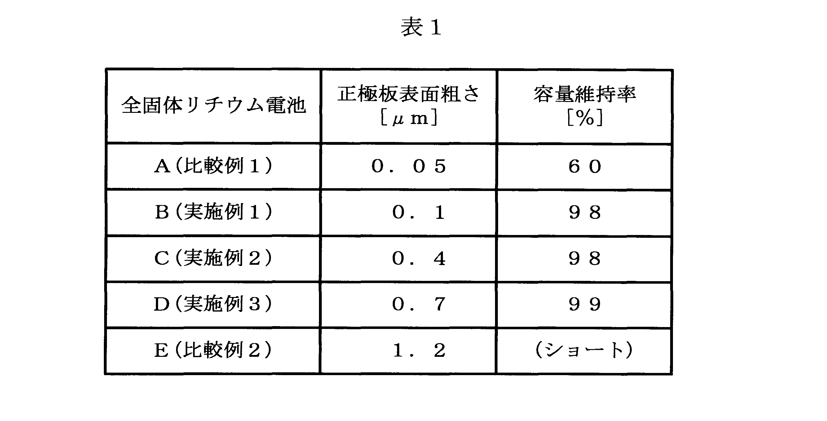
表1に示されるように、全固体リチウム電池A(比較例1)を使用した場合、正極板の表面(固体電解質層との界面)からの固体電解質層の剥離の発生によって、容量維持率が60%まで低下した。この場合、充放電時の正極板の体積膨張及び体積収縮によって正極板から固体電解質層が剥離し易くなりサイクル特性が低下した。また、全固体リチウム電池E(比較例2)を使用した場合、充放電サイクル試験時に正極板の表面の凹凸部分に局部的な電界集中が生じることでショートした。このように、正極板の表面粗さRaが0.1μmを下回る場合や、0.7μmを上回る場合には、発明者が所望する高性能の全固体リチウム電池が得られない。これに対して、全固体リチウム電池B~D(実施例1~3)を使用した場合はいずれも、正極板からの固体電解質層の剥離が発生することなく、容量維持率が98%以上の高いレベルに維持されることが確認された。従って、正極板の表面粗さRaを0.1μm~0.7μmまでの範囲に調整することによって、容量低下が少ない高性能の全固体リチウム電池を提供できることが確認された。
表1に示されるように、全固体リチウム電池A(比較例1)を使用した場合、正極板の表面(固体電解質層との界面)からの固体電解質層の剥離の発生によって、容量維持率が60%まで低下した。この場合、充放電時の正極板の体積膨張及び体積収縮によって正極板から固体電解質層が剥離し易くなりサイクル特性が低下した。また、全固体リチウム電池E(比較例2)を使用した場合、充放電サイクル試験時に正極板の表面の凹凸部分に局部的な電界集中が生じることでショートした。このように、正極板の表面粗さRaが0.1μmを下回る場合や、0.7μmを上回る場合には、発明者が所望する高性能の全固体リチウム電池が得られない。これに対して、全固体リチウム電池B~D(実施例1~3)を使用した場合はいずれも、正極板からの固体電解質層の剥離が発生することなく、容量維持率が98%以上の高いレベルに維持されることが確認された。従って、正極板の表面粗さRaを0.1μm~0.7μmまでの範囲に調整することによって、容量低下が少ない高性能の全固体リチウム電池を提供できることが確認された。
100…全固体リチウム電池(全固体電池)、101…正極側集電極、102…負極側集電極、103,104…外装材、105…集電接続層、106…正極板(コバルト酸リチウム配向焼結板)、106a…固体電解質層側表面、107…固体電解質層、108…負極層、110…正極、120…負極
Claims (5)
- 酸化物系セラミックス材料からなる固体電解質層を含む全固体電池の正極を構成する全固体電池用正極板であって、
前記固体電解質層が形成される固体電解質層側表面の表面粗さが0.1μmから0.7μmまでの範囲にある、全固体電池用正極板。 - 請求項1に記載の全固体電池用正極板であって、
前記固体電解質層側表面に形成される前記固体電解質層の厚さが0.5μmから3.0μmまでの範囲にある、全固体電池用正極板。 - 請求項1又は2に記載の全固体電池用正極板であって、
厚さが10μmから60μmまでの範囲にある、全固体電池用正極板。 - 請求項1~3のうちのいずれか一項に記載の全固体電池用正極板であって、
コバルト酸リチウムを含み、前記固体電解質層が酸化物系セラミックス材料のうちの1つであるリン酸リチウムオキシナイトライド系セラミックス材料からなる、全固体電池用正極板。 - 正極板と、前記正極板の表面に形成された固体電解質層と、を含む全固体電池であって、
前記正極板が請求項1~4のうちのいずれか一項に記載の全固体電池用正極板である、全固体電池。
Priority Applications (3)
| Application Number | Priority Date | Filing Date | Title |
|---|---|---|---|
| CN201680006467.4A CN107210427A (zh) | 2015-01-23 | 2016-01-18 | 全固体电池用正极板、全固体电池 |
| JP2016570623A JPWO2016117499A1 (ja) | 2015-01-23 | 2016-01-18 | 全固体電池用正極板、全固体電池 |
| US15/655,046 US20170317334A1 (en) | 2015-01-23 | 2017-07-20 | Cathode plate for all-solid battery, and all-solid battery |
Applications Claiming Priority (4)
| Application Number | Priority Date | Filing Date | Title |
|---|---|---|---|
| JP2015-010842 | 2015-01-23 | ||
| JP2015010842 | 2015-01-23 | ||
| JP2015-031192 | 2015-02-20 | ||
| JP2015031192 | 2015-02-20 |
Related Child Applications (1)
| Application Number | Title | Priority Date | Filing Date |
|---|---|---|---|
| US15/655,046 Continuation US20170317334A1 (en) | 2015-01-23 | 2017-07-20 | Cathode plate for all-solid battery, and all-solid battery |
Publications (1)
| Publication Number | Publication Date |
|---|---|
| WO2016117499A1 true WO2016117499A1 (ja) | 2016-07-28 |
Family
ID=56417044
Family Applications (1)
| Application Number | Title | Priority Date | Filing Date |
|---|---|---|---|
| PCT/JP2016/051267 Ceased WO2016117499A1 (ja) | 2015-01-23 | 2016-01-18 | 全固体電池用正極板、全固体電池 |
Country Status (4)
| Country | Link |
|---|---|
| US (1) | US20170317334A1 (ja) |
| JP (1) | JPWO2016117499A1 (ja) |
| CN (1) | CN107210427A (ja) |
| WO (1) | WO2016117499A1 (ja) |
Cited By (9)
| Publication number | Priority date | Publication date | Assignee | Title |
|---|---|---|---|---|
| WO2017146088A1 (ja) * | 2016-02-24 | 2017-08-31 | 日本碍子株式会社 | 板状リチウム複合酸化物 |
| WO2017188233A1 (ja) * | 2016-04-25 | 2017-11-02 | 日本碍子株式会社 | 正極 |
| WO2019003846A1 (ja) * | 2017-06-28 | 2019-01-03 | 日本電気硝子株式会社 | 全固体ナトリウムイオン二次電池 |
| US10629905B2 (en) | 2016-04-25 | 2020-04-21 | Ngk Insulators, Ltd. | Positive electrode |
| US20210043919A1 (en) * | 2018-05-17 | 2021-02-11 | Ngk Insulators, Ltd. | COIN-SHAPED LITHIUM SECONDARY BATTERY AND IoT DEVICE |
| US20210066745A1 (en) * | 2018-05-17 | 2021-03-04 | Ngk Insulators, Ltd. | Lithium secondary battery |
| JP2022060596A (ja) * | 2017-05-30 | 2022-04-14 | 三星電子株式会社 | 全固体二次電池 |
| US11799171B2 (en) | 2017-05-30 | 2023-10-24 | Samsung Electronics Co., Ltd. | All-solid secondary battery and method of preparing the same |
| US12243979B2 (en) | 2020-11-19 | 2025-03-04 | Samsung Electronics Co., Ltd. | All-solid battery and method of preparing the same |
Families Citing this family (10)
| Publication number | Priority date | Publication date | Assignee | Title |
|---|---|---|---|---|
| WO2018118964A1 (en) | 2016-12-21 | 2018-06-28 | Corning Incorporated | Sintering system and sintered articles |
| JP2019200851A (ja) * | 2018-05-14 | 2019-11-21 | トヨタ自動車株式会社 | 固体電解質、全固体電池および固体電解質の製造方法 |
| JP7258045B2 (ja) | 2018-12-18 | 2023-04-14 | 日本碍子株式会社 | リチウム二次電池 |
| CN113196545B (zh) * | 2018-12-28 | 2025-01-28 | 松下知识产权经营株式会社 | 全固体电池和全固体电池的制造方法 |
| JP7465077B2 (ja) * | 2019-11-21 | 2024-04-10 | 太陽誘電株式会社 | 全固体電池とその製造方法 |
| JP7101655B2 (ja) * | 2019-12-16 | 2022-07-15 | 本田技研工業株式会社 | バッテリパック |
| CN111554967B (zh) * | 2020-03-06 | 2021-02-23 | 清陶(昆山)能源发展有限公司 | 一种全固态电池及其制备方法 |
| CN117096426A (zh) * | 2020-05-12 | 2023-11-21 | 苹果公司 | 固态锂电池的正极 |
| US20230275263A1 (en) * | 2020-07-03 | 2023-08-31 | Oerlikon Surface Solutions Ag, Pfäffikon | Method for manufacturing a solid-state battery |
| CN115332617B (zh) * | 2022-08-19 | 2025-12-09 | 西安铂力特增材技术股份有限公司 | 氧化物固态电池的制备工艺及固态电池 |
Citations (4)
| Publication number | Priority date | Publication date | Assignee | Title |
|---|---|---|---|---|
| WO2010074304A1 (ja) * | 2008-12-24 | 2010-07-01 | 日本碍子株式会社 | リチウム二次電池の正極活物質用の板状粒子、リチウム二次電池の正極活物質膜、これらの製造方法、リチウム二次電池の正極活物質の製造方法、及びリチウム二次電池 |
| JP2011124080A (ja) * | 2009-12-10 | 2011-06-23 | Sumitomo Electric Ind Ltd | 非水電解質電池用正極とその製造方法および非水電解質電池 |
| JP2014035818A (ja) * | 2012-08-07 | 2014-02-24 | Tdk Corp | 全固体リチウムイオン二次電池 |
| WO2015151566A1 (ja) * | 2014-03-31 | 2015-10-08 | 日本碍子株式会社 | 全固体リチウム電池 |
Family Cites Families (4)
| Publication number | Priority date | Publication date | Assignee | Title |
|---|---|---|---|---|
| KR100570677B1 (ko) * | 2003-09-26 | 2006-04-12 | 삼성에스디아이 주식회사 | 리튬 이차 전지 |
| JP2010097843A (ja) * | 2008-10-17 | 2010-04-30 | Panasonic Corp | リチウムイオン二次電池 |
| EP2507858A1 (en) * | 2009-11-30 | 2012-10-10 | OC Oerlikon Balzers AG | Lithium ion battery and method for manufacturing of such battery |
| JP2012243710A (ja) * | 2011-05-24 | 2012-12-10 | Sumitomo Electric Ind Ltd | 非水電解質電池用正極およびその製造方法と非水電解質電池 |
-
2016
- 2016-01-18 JP JP2016570623A patent/JPWO2016117499A1/ja not_active Abandoned
- 2016-01-18 WO PCT/JP2016/051267 patent/WO2016117499A1/ja not_active Ceased
- 2016-01-18 CN CN201680006467.4A patent/CN107210427A/zh active Pending
-
2017
- 2017-07-20 US US15/655,046 patent/US20170317334A1/en not_active Abandoned
Patent Citations (4)
| Publication number | Priority date | Publication date | Assignee | Title |
|---|---|---|---|---|
| WO2010074304A1 (ja) * | 2008-12-24 | 2010-07-01 | 日本碍子株式会社 | リチウム二次電池の正極活物質用の板状粒子、リチウム二次電池の正極活物質膜、これらの製造方法、リチウム二次電池の正極活物質の製造方法、及びリチウム二次電池 |
| JP2011124080A (ja) * | 2009-12-10 | 2011-06-23 | Sumitomo Electric Ind Ltd | 非水電解質電池用正極とその製造方法および非水電解質電池 |
| JP2014035818A (ja) * | 2012-08-07 | 2014-02-24 | Tdk Corp | 全固体リチウムイオン二次電池 |
| WO2015151566A1 (ja) * | 2014-03-31 | 2015-10-08 | 日本碍子株式会社 | 全固体リチウム電池 |
Cited By (15)
| Publication number | Priority date | Publication date | Assignee | Title |
|---|---|---|---|---|
| WO2017146088A1 (ja) * | 2016-02-24 | 2017-08-31 | 日本碍子株式会社 | 板状リチウム複合酸化物 |
| US10454109B2 (en) | 2016-02-24 | 2019-10-22 | Ngk Insulators, Ltd. | Plate-shaped lithium composite oxide |
| US10637055B2 (en) | 2016-04-25 | 2020-04-28 | Ngk Insulators, Ltd. | Positive electrode |
| WO2017188233A1 (ja) * | 2016-04-25 | 2017-11-02 | 日本碍子株式会社 | 正極 |
| US10629905B2 (en) | 2016-04-25 | 2020-04-21 | Ngk Insulators, Ltd. | Positive electrode |
| JP7337984B2 (ja) | 2017-05-30 | 2023-09-04 | 三星電子株式会社 | 全固体二次電池 |
| JP2022060596A (ja) * | 2017-05-30 | 2022-04-14 | 三星電子株式会社 | 全固体二次電池 |
| US11799171B2 (en) | 2017-05-30 | 2023-10-24 | Samsung Electronics Co., Ltd. | All-solid secondary battery and method of preparing the same |
| WO2019003846A1 (ja) * | 2017-06-28 | 2019-01-03 | 日本電気硝子株式会社 | 全固体ナトリウムイオン二次電池 |
| US12224398B2 (en) | 2017-06-28 | 2025-02-11 | Nippon Electric Glass Co., Ltd. | All-solid-state sodium ion secondary battery |
| US20210043919A1 (en) * | 2018-05-17 | 2021-02-11 | Ngk Insulators, Ltd. | COIN-SHAPED LITHIUM SECONDARY BATTERY AND IoT DEVICE |
| US20210066745A1 (en) * | 2018-05-17 | 2021-03-04 | Ngk Insulators, Ltd. | Lithium secondary battery |
| US11996544B2 (en) * | 2018-05-17 | 2024-05-28 | Ngk Insulators, Ltd. | Coin-shaped lithium secondary battery and IoT device |
| US12183874B2 (en) * | 2018-05-17 | 2024-12-31 | Ngk Insulators, Ltd. | Lithium secondary battery |
| US12243979B2 (en) | 2020-11-19 | 2025-03-04 | Samsung Electronics Co., Ltd. | All-solid battery and method of preparing the same |
Also Published As
| Publication number | Publication date |
|---|---|
| CN107210427A (zh) | 2017-09-26 |
| US20170317334A1 (en) | 2017-11-02 |
| JPWO2016117499A1 (ja) | 2017-11-02 |
Similar Documents
| Publication | Publication Date | Title |
|---|---|---|
| WO2016117499A1 (ja) | 全固体電池用正極板、全固体電池 | |
| JP6646666B2 (ja) | 全固体リチウム電池 | |
| JP6374634B1 (ja) | リチウム複合酸化物焼結体板 | |
| JP5731278B2 (ja) | 全固体リチウムイオン電池 | |
| JP6019269B2 (ja) | コバルト酸リチウム配向焼結板の製造方法 | |
| JP6277079B2 (ja) | 全固体リチウム電池 | |
| JP6246079B2 (ja) | リチウム二次電池用正極活物質板の製造方法 | |
| WO2017065035A1 (ja) | 全固体リチウム電池 | |
| JP2009206094A (ja) | リチウムイオン二次電池の製造方法 | |
| JP6433086B2 (ja) | 全固体リチウム電池 | |
| WO2018155155A1 (ja) | リチウム複合酸化物焼結体板 | |
| JP6660766B2 (ja) | 全固体電池の製造方法 | |
| WO2015146315A1 (ja) | 全固体電池 | |
| WO2017065034A1 (ja) | 全固体リチウム電池の製造方法 | |
| JP2016115681A (ja) | リチウム電池用負極層、リチウム電池 | |
| JP2017036185A (ja) | Co3O4含有配向焼結板及びコバルト酸リチウム配向焼結板の製造方法 | |
| JP2010132528A (ja) | セラミックスシート及びその製造方法 | |
| JP2017024952A (ja) | コバルト酸リチウム配向焼結板の製造方法 | |
| JP2016072241A (ja) | コバルト酸リチウム配向焼結板及びその製造方法、並びにコバルト酸リチウム配向焼結板への固体電解質層の形成方法 | |
| JP6823597B2 (ja) | リチウム二次電池用配向正極板 | |
| WO2018155156A1 (ja) | リチウム複合酸化物焼結体板 | |
| JP2016105376A (ja) | コバルト酸リチウム配向焼結板の製造方法 | |
| WO2017104363A1 (ja) | 板状リチウム複合酸化物、及びその製造方法 | |
| JP2016069269A (ja) | コバルト酸リチウム配向焼結板の製造方法 | |
| WO2018155154A1 (ja) | リチウム複合酸化物焼結体板 |
Legal Events
| Date | Code | Title | Description |
|---|---|---|---|
| 121 | Ep: the epo has been informed by wipo that ep was designated in this application |
Ref document number: 16740106 Country of ref document: EP Kind code of ref document: A1 |
|
| ENP | Entry into the national phase |
Ref document number: 2016570623 Country of ref document: JP Kind code of ref document: A |
|
| NENP | Non-entry into the national phase |
Ref country code: DE |
|
| 122 | Ep: pct application non-entry in european phase |
Ref document number: 16740106 Country of ref document: EP Kind code of ref document: A1 |