WO2016117467A1 - 車両の走行制御装置及び走行制御方法 - Google Patents
車両の走行制御装置及び走行制御方法 Download PDFInfo
- Publication number
- WO2016117467A1 WO2016117467A1 PCT/JP2016/051121 JP2016051121W WO2016117467A1 WO 2016117467 A1 WO2016117467 A1 WO 2016117467A1 JP 2016051121 W JP2016051121 W JP 2016051121W WO 2016117467 A1 WO2016117467 A1 WO 2016117467A1
- Authority
- WO
- WIPO (PCT)
- Prior art keywords
- vehicle
- determination
- lane
- recognition
- white line
- Prior art date
- Legal status (The legal status is an assumption and is not a legal conclusion. Google has not performed a legal analysis and makes no representation as to the accuracy of the status listed.)
- Ceased
Links
Images



Classifications
-
- B—PERFORMING OPERATIONS; TRANSPORTING
- B60—VEHICLES IN GENERAL
- B60W—CONJOINT CONTROL OF VEHICLE SUB-UNITS OF DIFFERENT TYPE OR DIFFERENT FUNCTION; CONTROL SYSTEMS SPECIALLY ADAPTED FOR HYBRID VEHICLES; ROAD VEHICLE DRIVE CONTROL SYSTEMS FOR PURPOSES NOT RELATED TO THE CONTROL OF A PARTICULAR SUB-UNIT
- B60W30/00—Purposes of road vehicle drive control systems not related to the control of a particular sub-unit, e.g. of systems using conjoint control of vehicle sub-units
- B60W30/14—Adaptive cruise control
- B60W30/16—Control of distance between vehicles, e.g. keeping a distance to preceding vehicle
-
- B—PERFORMING OPERATIONS; TRANSPORTING
- B60—VEHICLES IN GENERAL
- B60W—CONJOINT CONTROL OF VEHICLE SUB-UNITS OF DIFFERENT TYPE OR DIFFERENT FUNCTION; CONTROL SYSTEMS SPECIALLY ADAPTED FOR HYBRID VEHICLES; ROAD VEHICLE DRIVE CONTROL SYSTEMS FOR PURPOSES NOT RELATED TO THE CONTROL OF A PARTICULAR SUB-UNIT
- B60W10/00—Conjoint control of vehicle sub-units of different type or different function
- B60W10/04—Conjoint control of vehicle sub-units of different type or different function including control of propulsion units
- B60W10/06—Conjoint control of vehicle sub-units of different type or different function including control of propulsion units including control of combustion engines
-
- B—PERFORMING OPERATIONS; TRANSPORTING
- B60—VEHICLES IN GENERAL
- B60W—CONJOINT CONTROL OF VEHICLE SUB-UNITS OF DIFFERENT TYPE OR DIFFERENT FUNCTION; CONTROL SYSTEMS SPECIALLY ADAPTED FOR HYBRID VEHICLES; ROAD VEHICLE DRIVE CONTROL SYSTEMS FOR PURPOSES NOT RELATED TO THE CONTROL OF A PARTICULAR SUB-UNIT
- B60W10/00—Conjoint control of vehicle sub-units of different type or different function
- B60W10/18—Conjoint control of vehicle sub-units of different type or different function including control of braking systems
-
- B—PERFORMING OPERATIONS; TRANSPORTING
- B60—VEHICLES IN GENERAL
- B60W—CONJOINT CONTROL OF VEHICLE SUB-UNITS OF DIFFERENT TYPE OR DIFFERENT FUNCTION; CONTROL SYSTEMS SPECIALLY ADAPTED FOR HYBRID VEHICLES; ROAD VEHICLE DRIVE CONTROL SYSTEMS FOR PURPOSES NOT RELATED TO THE CONTROL OF A PARTICULAR SUB-UNIT
- B60W40/00—Estimation or calculation of non-directly measurable driving parameters for road vehicle drive control systems not related to the control of a particular sub unit, e.g. by using mathematical models
- B60W40/02—Estimation or calculation of non-directly measurable driving parameters for road vehicle drive control systems not related to the control of a particular sub unit, e.g. by using mathematical models related to ambient conditions
- B60W40/04—Traffic conditions
-
- G—PHYSICS
- G08—SIGNALLING
- G08G—TRAFFIC CONTROL SYSTEMS
- G08G1/00—Traffic control systems for road vehicles
- G08G1/16—Anti-collision systems
- G08G1/167—Driving aids for lane monitoring, lane changing, e.g. blind spot detection
-
- B—PERFORMING OPERATIONS; TRANSPORTING
- B60—VEHICLES IN GENERAL
- B60W—CONJOINT CONTROL OF VEHICLE SUB-UNITS OF DIFFERENT TYPE OR DIFFERENT FUNCTION; CONTROL SYSTEMS SPECIALLY ADAPTED FOR HYBRID VEHICLES; ROAD VEHICLE DRIVE CONTROL SYSTEMS FOR PURPOSES NOT RELATED TO THE CONTROL OF A PARTICULAR SUB-UNIT
- B60W2420/00—Indexing codes relating to the type of sensors based on the principle of their operation
- B60W2420/40—Photo, light or radio wave sensitive means, e.g. infrared sensors
- B60W2420/403—Image sensing, e.g. optical camera
-
- B—PERFORMING OPERATIONS; TRANSPORTING
- B60—VEHICLES IN GENERAL
- B60W—CONJOINT CONTROL OF VEHICLE SUB-UNITS OF DIFFERENT TYPE OR DIFFERENT FUNCTION; CONTROL SYSTEMS SPECIALLY ADAPTED FOR HYBRID VEHICLES; ROAD VEHICLE DRIVE CONTROL SYSTEMS FOR PURPOSES NOT RELATED TO THE CONTROL OF A PARTICULAR SUB-UNIT
- B60W2554/00—Input parameters relating to objects
- B60W2554/80—Spatial relation or speed relative to objects
- B60W2554/801—Lateral distance
-
- B—PERFORMING OPERATIONS; TRANSPORTING
- B60—VEHICLES IN GENERAL
- B60W—CONJOINT CONTROL OF VEHICLE SUB-UNITS OF DIFFERENT TYPE OR DIFFERENT FUNCTION; CONTROL SYSTEMS SPECIALLY ADAPTED FOR HYBRID VEHICLES; ROAD VEHICLE DRIVE CONTROL SYSTEMS FOR PURPOSES NOT RELATED TO THE CONTROL OF A PARTICULAR SUB-UNIT
- B60W2554/00—Input parameters relating to objects
- B60W2554/80—Spatial relation or speed relative to objects
- B60W2554/803—Relative lateral speed
-
- B—PERFORMING OPERATIONS; TRANSPORTING
- B60—VEHICLES IN GENERAL
- B60W—CONJOINT CONTROL OF VEHICLE SUB-UNITS OF DIFFERENT TYPE OR DIFFERENT FUNCTION; CONTROL SYSTEMS SPECIALLY ADAPTED FOR HYBRID VEHICLES; ROAD VEHICLE DRIVE CONTROL SYSTEMS FOR PURPOSES NOT RELATED TO THE CONTROL OF A PARTICULAR SUB-UNIT
- B60W2720/00—Output or target parameters relating to overall vehicle dynamics
- B60W2720/10—Longitudinal speed
-
- B—PERFORMING OPERATIONS; TRANSPORTING
- B60—VEHICLES IN GENERAL
- B60W—CONJOINT CONTROL OF VEHICLE SUB-UNITS OF DIFFERENT TYPE OR DIFFERENT FUNCTION; CONTROL SYSTEMS SPECIALLY ADAPTED FOR HYBRID VEHICLES; ROAD VEHICLE DRIVE CONTROL SYSTEMS FOR PURPOSES NOT RELATED TO THE CONTROL OF A PARTICULAR SUB-UNIT
- B60W2754/00—Output or target parameters relating to objects
- B60W2754/10—Spatial relation or speed relative to objects
- B60W2754/30—Longitudinal distance
-
- B—PERFORMING OPERATIONS; TRANSPORTING
- B60—VEHICLES IN GENERAL
- B60W—CONJOINT CONTROL OF VEHICLE SUB-UNITS OF DIFFERENT TYPE OR DIFFERENT FUNCTION; CONTROL SYSTEMS SPECIALLY ADAPTED FOR HYBRID VEHICLES; ROAD VEHICLE DRIVE CONTROL SYSTEMS FOR PURPOSES NOT RELATED TO THE CONTROL OF A PARTICULAR SUB-UNIT
- B60W30/00—Purposes of road vehicle drive control systems not related to the control of a particular sub-unit, e.g. of systems using conjoint control of vehicle sub-units
- B60W30/18—Propelling the vehicle
- B60W30/18009—Propelling the vehicle related to particular drive situations
- B60W30/18163—Lane change; Overtaking manoeuvres
Definitions
- the present disclosure relates to a travel control technique for controlling the travel of a vehicle equipped with an imaging device.
- a vehicle traveling in the own lane that is the same lane as the traveling lane of the own vehicle is selected as a preceding vehicle from the preceding vehicles traveling in front of the own vehicle, and the selected preceding vehicle is selected.
- Following control is known in which the vehicle travels following the vehicle.
- follow-up control for example, it is important to accurately select a vehicle traveling in its own lane from vehicles detected by a distance measuring sensor, a vehicle-mounted camera, or the like. Therefore, conventionally, a predicted route, which is a future travel route of the host vehicle, is calculated by calculation, and control is performed with a vehicle existing on the calculated predicted route as a target vehicle for follow-up control.
- Patent Document 1 discloses the following technique as a method for selecting a preceding vehicle to be subject to tracking control.
- a turning circle calculated based on the yaw rate and the vehicle speed is set as the predicted course of the host vehicle.
- the own lane probability that is the probability that the preceding vehicle exists in the own lane is calculated according to the offset distance of the lateral position that is the lateral position between the track of the own vehicle and the preceding vehicle. .
- a preceding vehicle to be followed is selected according to the calculated own lane probability.
- Patent Document 2 discloses the following technology.
- a lateral movement speed that is a movement speed in the lane lateral direction of the preceding vehicle is calculated.
- a predicted lateral position that is a lateral position of the preceding vehicle predicted according to the calculated lateral movement speed is calculated, and a preceding vehicle to be followed is selected based on the calculated predicted lateral position.
- This disclosure is intended to provide a vehicle travel control technology that can improve the stability of selection / non-selection of a preceding vehicle.
- the travel control device of the present disclosure employs the following means.
- the present disclosure relates to a vehicle travel control device applied to a vehicle equipped with an imaging device that captures the front of the host vehicle.
- the travel control device includes a lane line recognition unit that recognizes a travel lane line that divides the own lane, which is a travel lane of the host vehicle, based on an image acquired by the imaging device, and a front that travels ahead of the host vehicle.
- Vehicle determining means for determining that the vehicle is an interrupting vehicle that interrupts the own lane and that determines that the preceding vehicle traveling in the own lane is a leaving vehicle that leaves the own lane, and that performs an interrupt determination and a departure determination of another vehicle.
- the travel control device of the present disclosure is configured to perform the interrupt determination and the departure determination of the other vehicle based on the relative position in the vehicle width direction of the preceding vehicle with respect to the travel lane marking.
- the forward vehicle traveling in the adjacent lane is determined as an interrupt vehicle to the own lane based on the relative position in the vehicle width direction of the forward vehicle with respect to the travel lane marking. And it was set as the structure which determines the front vehicle which drive
- the travel control device of the present disclosure it is possible to accurately determine the interruption and departure of the preceding vehicle even when the host vehicle is traveling to the right or left of the host lane.
- the travel control device of the present disclosure can improve the stability of selection / non-selection of the preceding vehicle that is the target of the follow-up control when the lane of the preceding vehicle is changed.
- FIG. 1 is a block diagram showing a schematic configuration of a vehicle travel control device.
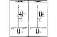
- FIG. 2 is a diagram for explaining interrupt determination and departure determination of another vehicle by the first determination means.
- FIG. 3 is a diagram for explaining interrupt determination and departure determination of another vehicle by the second determination means.
- FIG. 4 is a flowchart showing a processing procedure for interrupt determination and departure determination of another vehicle.
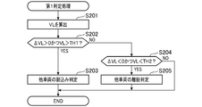
- FIG. 5 is a flowchart illustrating a processing procedure of the first determination process.
- the travel control device is mounted on a vehicle and follows a preceding vehicle that travels in the same lane as the traveling lane of the host vehicle among the preceding vehicles that travel in front of the host vehicle and travels the host vehicle.
- Implement control In the follow-up control according to the present embodiment, the inter-vehicle distance between the host vehicle and the preceding vehicle is controlled.
- a travel control device 10 is a computer including a CPU, a ROM, a RAM, an I / O, and the like.
- the travel control device 10 includes functional units such as a white line recognition unit 11, an interruption departure determination unit 12, a preceding vehicle selection unit 13, and a control target value calculation unit 14.
- the CPU implements the above functions by executing a program installed in the ROM.
- a vehicle (host vehicle) on which the travel control device 10 is mounted is equipped with object detection means for detecting an object existing around the vehicle.
- the imaging device 21 and the radar device 22 are mounted as object detection means.
- the travel control device 10 receives object detection information from the object detection means, and executes tracking control for the preceding vehicle based on the input information.
- the imaging device 21 is an in-vehicle camera, and is composed of a CCD camera, a CMOS image sensor, a near infrared camera, and the like.
- the imaging device 21 captures the surrounding environment (vehicle periphery) of the host vehicle including the traveling road, and generates image data of the captured image.
- the imaging device 21 sequentially outputs the generated image data to the travel control device 10.
- the imaging device 21 is installed in the vicinity of the upper end of the windshield of the vehicle, and has a region (detectable region of the imaging device 21) that spreads over a range of a predetermined imaging angle ⁇ 1 toward the front of the vehicle around the imaging axis. Take a picture.
- the imaging device 21 may be a monocular camera or a stereo camera.
- the radar device 22 is an exploration device that detects an object by transmitting an electromagnetic wave as a transmission wave and receiving a reflected wave with respect to the transmission wave. In the present embodiment, it is configured by a millimeter wave radar.
- the radar device 22 is attached to the front portion of the host vehicle, and extends over a range of a predetermined radar angle ⁇ 2 ( ⁇ 2 ⁇ 1) about the optical axis toward the front of the vehicle (detectable region of the radar device 22). Are scanned with a radar signal.
- the radar device 22 generates distance measurement data of the detected object based on the time from when the electromagnetic wave is transmitted toward the front of the vehicle until the reflected wave is received.
- the radar device 22 sequentially outputs the generated distance measurement data to the travel control device 10.
- the distance measurement data includes information regarding the direction in which the object is present with respect to the host vehicle, the distance from the host vehicle to the object, and the relative speed of the object with respect to the host vehicle.
- the imaging device 21 and the radar device 22 have the same direction as the direction in which the imaging axis that is the reference axis of the imaging device 21 and the optical axis that is the reference axis of the radar device 22 are parallel to the road surface of the traveling road of the host vehicle. It is attached to become. Some areas of the detectable region of the imaging device 21 and the detectable region of the radar device 22 overlap each other.
- the travel control device 10 receives image data from the imaging device 21 and distance measurement data from the radar device 22. In addition, the traveling control device 10 receives detection signals from various other sensors provided in the vehicle. As other various sensors, a yaw rate sensor 23, a vehicle speed sensor 24, a steering angle sensor 25, an ACC switch 26, and the like are provided.
- the yaw rate sensor 23 detects an angular velocity (yaw rate) in the turning direction of the vehicle.
- the vehicle speed sensor 24 detects the vehicle speed of the vehicle.
- the steering angle sensor 25 detects the steering angle of the vehicle.
- the ACC switch 26 is an input switch for selecting whether to execute the follow-up control mode in the vehicle.
- the traveling control device 10 includes a white line recognition unit 11, an interruption departure determination unit 12, a preceding vehicle selection unit 13, and a control target value calculation unit 14.
- the white line recognition unit 11 functions as a lane marking recognition unit that recognizes a white line on the road surface as a lane marking that divides the own lane that is the lane of the host vehicle.
- the white line is recognized by the following method.
- the white line recognition unit 11 receives image data from the imaging device 21 and extracts edge points as white line candidates from the input image data based on the change rate of luminance in the horizontal direction of the input image.
- the white line recognition unit 11 sequentially stores the extracted edge points for each frame, and recognizes the white line based on the stored history of edge points.
- the white line recognition unit 11 stores the recognition result as white line information (recognized travel division line information).
- the interruption departure determination unit 12 functions as a vehicle determination unit that determines, from among the objects detected by the object detection unit, an interruption vehicle that interrupts the vehicle lane that is the traveling lane of the vehicle and a vehicle that leaves the vehicle lane. . That is, the interruption leaving determination unit 12 corresponds to an interruption determining function and a leaving determination function of another vehicle.
- the object detected by the object detection means is also referred to as a “target”.
- the target detected by the imaging device 21 and the target detected by the radar device 22 belong to the same object (image data and measurement including targets belonging to the same object). For distance data, data is merged.
- the interruption leaving determination unit 12 determines the presence or absence of a forward vehicle for a target (fusion target) obtained by data fusion. When it is determined that there is a preceding vehicle, the interrupt / leave determination unit 12 performs an interrupt determination and a departure determination of another vehicle.
- data fusion for image data and distance measurement data, a plurality of detection points existing within a predetermined fusion range are fused as data belonging to the same object.
- image data and distance measurement data corresponding to the detected target are set as data belonging to the same object.
- the data fusion method is not limited to this.
- the preceding vehicle selection unit 13 selects / deselects the preceding vehicle to be subject to follow-up control from the objects detected by the object detection unit based on the determination result of the interruption / leaving of another vehicle by the interruption / leaving determination unit 12. Do.
- the travel control apparatus 10 has a vehicle's own vehicle according to an offset position (hereinafter referred to as a “lateral offset position”) that is a relative position to the host vehicle in the vehicle width direction (lateral direction) of the preceding vehicle.
- lateral offset position an offset position
- the travel control device 10 holds map data in which the lateral offset position of the preceding vehicle and the own lane probability are associated in advance in a predetermined storage area (for example, a memory).
- the preceding vehicle selection unit 13 reads the own lane probability corresponding to the offset position in the lateral direction of the preceding vehicle from the data of the basic map, and corrects the read own lane probability according to the determination result of the interruption departure determination unit 12.
- the preceding vehicle selection unit 13 selects a preceding vehicle having a corrected own lane probability that is equal to or greater than a predetermined value as a preceding vehicle subject to follow-up control.
- the selection as the preceding vehicle subject to tracking control is canceled.
- the position coordinate in the vehicle width direction (lateral direction) detected by the imaging device 21 is corrected based on the estimated R that is the curve radius of the predicted course (curve) in the host vehicle.
- the center position in the lateral direction of the target corresponding to the preceding vehicle is set as the lateral offset position of the preceding vehicle.
- the travel control apparatus 10 is configured to maintain the inter-vehicle distance between the preceding vehicle selected by the preceding vehicle selection unit 13 and the own vehicle at a preset target interval. (Travel speed) is controlled.
- the control target value calculation unit 14 calculates a control target value for performing such vehicle speed control. Specifically, the control target value calculation unit 14 calculates a control value such as a target output of the in-vehicle engine and a required brake force, and outputs the calculated control value as a control signal to the engine electronic control unit (engine ECU 31).
- the travel control apparatus 10 according to the present embodiment is configured to output a control signal to the engine ECU 31 and to output a control signal from the engine ECU 31 to the brake electronic control unit (brake ECU 32).
- the control signal output configuration is not limited to this.
- the travel control device 10 may be configured to output a control signal to each of the engine ECU 31 and the brake ECU 32.
- the interruption departure determination unit 12 performs a plurality of determination processes in which determination parameters used for determination of interruption and departure of the preceding vehicle with respect to the own lane that is the traveling lane of the own vehicle are different. Specifically, the interruption leaving determination unit 12 interrupts other vehicles based on the relative position in the vehicle width direction (lateral direction) of the preceding vehicle based on the white line (recognition division line) recognized by the white line recognition unit 11. And first determination means for determining separation.
- the interruption departure determination unit 12 includes second determination means for determining interruption and separation of another vehicle based on the relative position in the vehicle width direction (lateral direction) of the preceding vehicle with reference to the own vehicle.
- the interruption leaving determination unit 12 determines whether another vehicle interrupts and leaves (first determination process) by the first determination unit, or determines whether another vehicle interrupts by the second determination unit, depending on whether a predetermined execution condition is successful.
- a departure determination (second determination process) is performed.
- FIG. 2 shows a case where the forward vehicle 51 exists within the range of the detection distance of the white line 61 detected by the imaging device 21 mounted on the host vehicle 50 (the recognition distance of the recognition partition line by the white line recognition unit 11). Is shown.
- FIG. 2 shows an example in which the imaging device 21 detects the white line 61a on the right side and the white line 61b on the left side with respect to the traveling direction of the host vehicle 50.
- the forward vehicle 51 traveling in the adjacent lane 64 adjacent to the own lane 63 changes to the own lane 63 and enters the front of the own vehicle 50.
- the forward vehicle 51 gradually approaches the white line 61a on the right side with respect to the traveling direction of the host vehicle 50, and eventually steps over the white line 61a.
- the forward vehicle 51 moves from the adjacent lane 64 to the own lane 63.
- a case is assumed in which the forward vehicle 51 traveling in the same lane (own lane 63) as the own vehicle 50 changes to the adjacent lane 64 and leaves the own lane 63. In this case, as shown in FIG.
- the forward vehicle 51 gradually approaches the white line 61a on the right side with respect to the traveling direction of the host vehicle 50, and eventually steps over the white line 61a.
- the forward vehicle 51 moves from the own lane 63 to the adjacent lane 64. That is, when the lane of the forward vehicle 51 is changed, the forward vehicle 51 moves across the white line 61a in the lateral direction (arrow direction) that is the vehicle width direction. Thereby, the relative position in the vehicle width direction (lateral direction) of the forward vehicle 51 with respect to the white line 61 changes.
- the relative position in the vehicle width direction (lateral direction) of the front vehicle 51 with respect to the white line 61 is used to determine the front vehicle 51.
- An interruption to the own lane 63 and a departure from the own lane 63 are determined.
- the interruption determination and the departure determination of the other vehicle Has been implemented.
- the interruption leaving determination unit 12 executes the following first determination process.
- the interruption departure determination unit 12 calculates a white line straddling amount VL that represents the degree of straddling of the front vehicle 51 with respect to the white line 61 as a parameter that represents the relative position of the front vehicle 51 in the vehicle width direction (lateral direction) with respect to the white line 61.
- the interruption departure determination unit 12 performs interruption determination and separation determination of another vehicle based on the calculated white line straddling amount VL.
- the “stretching degree” here is an amount that the vehicle straddles the white line 61, in other words, an amount that the vehicle crosses the white line 61 and enters another lane.
- the white line straddling amount VL is an amount by which the forward vehicle 51 straddles the white line 61a.
- the distance in the lateral direction from the left side surface to the white line 61 a in the traveling direction of the forward vehicle 51 is represented.
- the white line straddling amount VL is zero when the left side surface of the forward vehicle 51 is located on the white line 61a and is closest to the white line 61a, and the forward vehicle 51 If the white line 61a is stepped on by moving in the direction, a positive value is obtained. Thereby, as shown in FIG.
- the interruption leaving determination unit 12 has a positive value for the time series change amount of the white line straddling amount VL (a change amount ⁇ VL per unit time is a positive value),
- the white line straddling amount VL is larger than the first threshold value TH1
- the preceding vehicle 51 is determined as an interrupting vehicle to the own lane 63.
- the interrupt detachment determination unit 12 has a negative time-series change amount of the white line straddling amount VL (a change amount ⁇ VL per unit time is a negative value),
- the white line straddling amount VL is smaller than the second threshold value TH ⁇ b> 2
- the front vehicle 51 is determined to be a departure vehicle from the own lane 63.
- the interruption determination and departure determination of another vehicle by the second determination means will be described with reference to FIG.
- the front vehicle 51 exists outside the detection distance of the white line 61 by the imaging device 21 (the recognition distance of the recognition partition line by the white line recognition unit 11). It is assumed that the relative position in the vehicle width direction (lateral direction) cannot be used.
- the interruption determination and departure determination of the other vehicle by the second determination means are performed using the relative position in the vehicle width direction (lateral direction) of the preceding vehicle 51 calculated based on the own vehicle 50 as a determination parameter. It is the 2nd determination process which implements.
- the interruption leaving determination unit 12 executes the following second determination process.
- the interruption departure determination unit 12 uses the X axis of the front vehicle 51 based on the own vehicle 50 based on an orthogonal coordinate system in which the vehicle width direction (lateral direction) of the vehicle is the X axis and the traveling direction of the vehicle is the Y axis.
- An offset position (lateral offset position) Rx which is a position coordinate in the direction is calculated.
- the interruption leaving determination unit 12 determines the calculated offset position (lateral offset position of the forward vehicle 51) Rx and the lateral movement speed (the lateral movement speed of the forward vehicle 51) represented by the time derivative of the offset position Rx. Based on Vf, an interrupt determination and a departure determination of another vehicle are performed.
- the interruption leaving determination unit 12 differs in the sign of the lateral offset position Rx of the forward vehicle 51 and the sign of the lateral movement speed Vf of the forward vehicle 51.
- the preceding vehicle 51 is determined to be an interrupted vehicle.
- the interruption leaving determination unit 12 has the same sign as the sign of the lateral offset position Rx of the forward vehicle 51 and the sign of the lateral movement speed Vf of the forward vehicle 51.
- the preceding vehicle 51 is determined as a departure vehicle.
- the interruption leaving determination unit 12 sets the first condition that the traveling state of the host vehicle 50 is stable with respect to the white line 61, and determines whether another vehicle is interrupted on the condition that the first condition is satisfied. And carry out withdrawal determination.
- the following three conditions are included as the first condition.
- the lateral position of the host vehicle 50 in the host lane 63 can be acquired from the white line information.
- the lateral movement speed Vf of the preceding vehicle 51 can be calculated. That is, the lateral fluctuation width of the host vehicle 50 is not more than a predetermined value.
- III The state in which the lateral movement amount of the host vehicle 50 is equal to or less than the threshold value and the movement amount is equal to or less than the threshold value continues for a predetermined time or more.
- the interruption leaving determination unit 12 determines that the first condition is satisfied when all of these three conditions are satisfied, and determines that the traveling state of the host vehicle 50 is stable with respect to the white line 61. It functions as a determination means.
- the first determination means and the second determination means give priority to the interruption determination and the separation determination of another vehicle by the first determination means.
- the interrupt / leave determination unit 12 determines whether or not the forward vehicle 51 detected by the object detection unit is within the recognition distance range of the white line 61 recognized by the white line recognition unit 11. It functions as a determination means.
- the interruption / departure determination unit 12 prohibits the second determination unit from performing an interrupt determination and a departure determination of another vehicle. That is, at the time of white line recognition, selection of an interrupting vehicle and a leaving vehicle using the lateral offset position Rx of the preceding vehicle 51 as a determination parameter is not performed.
- the interrupt / leave determination unit 12 performs an interrupt determination and a departure determination of another vehicle by the second determination unit. This is because when the preceding vehicle 51 exists outside the range of the recognition distance of the white line 61, it is impossible to make an interrupt determination and a departure determination of another vehicle using the white line 61.
- the interruption leaving determination unit 12 sets the second condition that the preceding vehicle 51 is within the recognition distance range of the white line 61, and sets the other vehicle's condition on the condition that the second condition is satisfied. Perform interrupt determination and leave determination.
- interrupt determination and departure determination processing of another vehicle executed in the travel control device 10 will be described using the flowcharts of FIGS. 4 and 5.
- the main routine of FIG. 4 will be described. This process is executed at predetermined intervals by the interruption leaving determination unit 12 included in the travel control device 10 when the ACC switch 26 is turned on (when the tracking control mode in the vehicle is executed).
- the interruption leaving determination unit 12 determines whether or not the forward vehicle 51 is detected by the object detection means (step S100). In the process of step S100, the presence or absence of the forward vehicle 51 is determined for the fusion target. In addition, when there are a plurality of front vehicles 51, the vehicle to be determined at this time is selected from the plurality of front vehicles 51 that exist. As a result, when the interruption leaving determination unit 12 determines that the front vehicle 51 is not detected (the front vehicle 51 does not exist) (step S100: NO), this routine is ended. On the other hand, when the interruption leaving determination unit 12 determines that the front vehicle 51 is detected (the front vehicle 51 exists) (step S100: YES), the process proceeds to step S101. The interruption leaving determination unit 12 acquires the white line information calculated based on the image data of the imaging device 21 from the white line recognition unit 11 (step S101).
- the interruption departure determination unit 12 determines whether or not the traveling state of the host vehicle 50 is stable with respect to the white line 61 based on the result of establishment of the first condition (step S102). As a result, the interruption leaving determination unit 12 ends the routine when determining that the first condition is not satisfied and the traveling state of the host vehicle 50 is not stable with respect to the white line 61 (step S102: NO). To do. On the other hand, when the first condition is satisfied and the traveling state of the host vehicle 50 is determined to be stable with respect to the white line 61 (step S102: YES), the interruption / leaving determination unit 12 proceeds to step S103, Two conditions are determined.
- the interruption departure determination unit 12 determines whether or not the forward vehicle 51 detected by the object detection unit exists within the recognition distance range of the white line 61 recognized based on the white line information (step S103). .
- the interruption leaving determination unit 12 determines the second condition using the image data of the imaging device 21 acquired from the white line recognition unit 11 together with the white line information in the process of step S101.
- step S104 the interruption leaving determination unit 12 proceeds to step S104 when the first condition and the second condition are satisfied.
- the interruption leaving determination unit 12 performs an interruption determination and a leaving determination of another vehicle by the first determination unit (step S104). At this time, the interruption leaving determination unit 12 also prohibits the interruption determination and the leaving determination of the other vehicle by the second determination means.
- step S105 the interruption leaving determination unit 12 determines that the preceding vehicle 51 does not exist within the recognition distance range of the white line 61 (ie, exists outside the recognition distance range) (step S103: NO)
- step S105 the interruption leaving determination unit 12 proceeds to step S105 when the first condition is satisfied and the second condition is not satisfied.
- the interruption leaving determination unit 12 performs an interruption determination and a leaving determination of another vehicle by the second determination unit (step S105).
- the interruption / leaving determination unit 12 calculates the white line straddling amount VL that represents the degree of straddling the front vehicle 51 with respect to the white line 61 using the image data of the imaging device 21 acquired from the white line recognition unit 11 (step). S201).
- the white line straddling amount VL is calculated by the following equation (1) using the vehicle width CW of the front vehicle 51 and the distance LA between the vehicle central axis of the front vehicle 51 and the white line 61. .
- VL CW / 2-LA (1)
- the distance LA is a value that can be detected from the image data of the imaging device 21, and in the process of step S201, the detected distance between the white line 61a that the preceding vehicle 51 is going to straddle when changing the lane and the vehicle central axis is determined. Use.
- the interruption leaving determination unit 12 determines whether the white line straddling amount VL is increasing and the white line straddling amount VL is larger than the first threshold value TH1 (step S202).
- the interruption leaving determination unit 12 determines that the white line straddling amount VL is increasing using the change amount ⁇ VL per unit time of the white line straddling amount VL, and when ⁇ VL is a positive value ( ⁇ VL> 0). In the case of).
- a positive value is set as the first threshold value TH1 in order to detect a state in which the forward vehicle 51 straddles the white line 61a provided between the own lane 63 and the adjacent lane 64. Has been.
- the interrupt leaving determination unit 12 has a tendency that the white line straddling amount VL is increasing ( ⁇ VL> 0) and the white line straddling amount VL is larger than the first threshold TH1 (VL> TH1) (step S202: YES). ), Go to step S203.
- the interruption leaving determination unit 12 determines that the preceding vehicle 51 is an interruption vehicle (step S203).
- step S202 when the white line straddling amount VL does not tend to increase ( ⁇ VL ⁇ 0) or the white line straddling amount VL is equal to or less than the first threshold value TH1 (VL ⁇ TH1) (step S202: NO), Proceed to S204.
- the interruption leaving determination unit 12 determines whether or not the white line straddling amount VL is decreasing and the white line straddling amount VL is smaller than the second threshold value TH2 (step S204).
- the interruption leaving determination unit 12 determines that the white line straddling amount VL is decreasing using the change amount ⁇ VL per unit time of the white line straddling amount VL, and when ⁇ VL is a negative value ( ⁇ VL ⁇ 0). In the case of).
- a positive value is set as the second threshold TH2 in order to detect a state in which the forward vehicle 51 straddles the white line 61a provided between the own lane 63 and the adjacent lane 64.
- the first threshold value TH1 and the second threshold value TH2 may be the same value or different values.
- the interruption leaving determination unit 12 determines that the white line straddling amount VL does not tend to decrease ( ⁇ VL ⁇ 0) or the white line straddling amount VL is equal to or greater than the second threshold TH2 (VL ⁇ TH2) (step S204: NO). This routine ends. On the other hand, if the white line straddling amount VL tends to decrease ( ⁇ VL ⁇ 0) and the white line straddling amount VL is smaller than the second threshold (VL ⁇ TH2) (step S204: YES), Proceed to step S205. The interruption leaving determination unit 12 determines that the preceding vehicle 51 is a leaving vehicle (step S205).
- step S204 it may be determined that the change amount ⁇ LV of the white line straddling amount VL is decreasing by determining whether or not the amount of decrease in the white line straddling amount VL per unit time is equal to or greater than a predetermined amount. .
- the travel control device 10 provides the following excellent effects.
- the travel control apparatus 10 determines the interruption of other vehicles based on the relative position in the vehicle width direction (lateral direction) of the front vehicle 51 with respect to the white line 61 that is the travel division line of the own lane 63. It was set as the structure which implements withdrawal determination. Specifically, the forward vehicle 51 traveling in the adjacent lane 64 is determined as an interrupt vehicle to the own lane 63, and the forward vehicle 51 traveling in the own lane 63 is determined as a departure vehicle from the own lane 63. did. With this configuration, in the travel control device 10 according to the present embodiment, even when the host vehicle 50 is traveling to the right side or the left side of the host lane 63, it is possible to accurately determine the interruption and departure of the front vehicle 51. . As a result, the travel control apparatus 10 according to the present embodiment can improve the stability of selection / non-selection of the preceding vehicle to be subject to the follow-up control when the lane of the forward vehicle 51 is changed.
- the travel control apparatus 10 based on the change amount in the relative position in the vehicle width direction (lateral direction) of the front vehicle 51 with respect to the white line 61 and the sign (change direction) of the change amount.
- the direction in which the relative position changes differs between when the preceding vehicle 51 cuts into the own lane 63 from the adjacent lane 64 and when the preceding vehicle 51 leaves the adjacent lane 64.
- the amount of change in the relative position can be used to determine the degree of straddling of the forward vehicle 51 with respect to the white line 61 (how much it has been straddled). In view of this, with the above configuration, in the travel control device 10 according to the present embodiment, it is possible to improve the determination accuracy of whether the preceding vehicle 51 is an interrupting vehicle or a leaving vehicle.
- the travel control apparatus 10 is configured such that the vehicle width direction of the front vehicle 51 with respect to the white line 61 is determined on the condition that the front vehicle 51 is determined to be within the recognition distance range of the white line 61. Based on the relative position in the (lateral direction), an interrupt determination and a departure determination of another vehicle are performed. In other words, the travel control device 10 according to the present embodiment can determine the vehicle width direction (horizontal direction) of the front vehicle 51 with the white line 61 as a reference only when an interrupt determination and a departure determination of another vehicle using the white line 61 are possible. The determination processing based on the relative position of the (direction) is performed. With this configuration, the traveling control device 10 according to the present embodiment can suppress erroneous determinations in interrupt determination and departure determination of other vehicles.
- the traveling control apparatus 10 determines the vehicle width direction (lateral direction) of the forward vehicle 51 with respect to the white line 61 when it is determined that the forward vehicle 51 is within the recognition distance range of the white line 61. ) Based on the relative position of the other vehicle, it is configured to perform interrupt determination and departure determination (determination processing by the first determination means). At this time, the travel control apparatus 10 according to the present embodiment determines the interruption determination and departure determination of the other vehicle based on the relative position in the vehicle width direction (lateral direction) of the preceding vehicle 51 with respect to the own vehicle 50 (second determination means). (Determination processing by) is prohibited.
- the traveling control device 10 determines that the preceding vehicle 51 is within the recognition distance range of the white line 61, the determination process by the first determination unit has priority over the second determination unit.
- the interruption determination and departure determination of the other vehicle by the second determination means for example, when the own vehicle 50 is traveling rightward or leftward of the own lane 63, the front vehicle 51 traveling in the adjacent lane 64 is defined as the interruption vehicle.
- the determination process by the second determination unit is lower in determination accuracy than the interruption determination and the departure determination of the other vehicle by the first determination unit. Therefore, with the above configuration, the traveling control apparatus 10 according to the present embodiment can increase the determination accuracy of the interrupt determination and the departure determination of the other vehicle as much as possible.
- the traveling control apparatus 10 performs the interruption determination and the departure determination of the other vehicle by the second determination unit when it is determined that the preceding vehicle 51 exists outside the recognition distance range of the white line 61.
- the configuration In a situation where it is not possible to execute interrupt determination and departure determination (determination by the first determination means) of another vehicle based on the relative position in the vehicle width direction (lateral direction) of the preceding vehicle 51 with respect to the white line 61, other determination means ( The second determination means) performs an interrupt determination and a departure determination of another vehicle.
- the second determination means performs an interrupt determination and a departure determination of another vehicle.
- the travel control apparatus 10 uses a white line straddling amount VL as a degree of straddling the front vehicle 51 with respect to the white line 61 as a parameter representing a relative position of the front vehicle 51 with respect to the white line 61 in the vehicle width direction (lateral direction). .
- the travel control device 10 according to the present embodiment is configured to perform interrupt determination and departure determination of other vehicles based on the white line straddling amount VL.
- the travel control apparatus 10 according to the present embodiment can accurately and quickly grasp that the lane change of the front vehicle 51 has been started based on the degree of straddling of the front vehicle 51 with respect to the white line 61.
- the travel control apparatus 10 according to the present embodiment can improve the stability and responsiveness of selection / deselection of the preceding vehicle to be subject to follow-up control.
- the traveling control apparatus 10 is configured such that the traveling direction of the host vehicle 50 is determined to be a state in which the traveling state of the host vehicle 50 is stable with respect to the white line 61. Based on the relative position in the (lateral direction), an interrupt determination and a departure determination of another vehicle are performed. For example, if the traveling state of the host vehicle 50 is not stable with respect to the white line 61, such as when the host vehicle 50 is about to change lanes or the host vehicle 50 is staggered, the front vehicle 51 is interrupted. There is a high possibility that the determination and the departure determination are erroneously performed (the possibility of erroneous determination). In view of this, with the above-described configuration, the travel control device 10 according to the present embodiment can suppress a decrease in the accuracy of interrupt determination and departure determination of other vehicles.
- the travel control apparatus 10 uses the white line straddling amount as the degree of straddling the front vehicle 51 with respect to the white line 61 as a parameter representing the relative position in the vehicle width direction (lateral direction) of the front vehicle 51 with respect to the white line 61. VL is used.
- the travel control device 10 according to the present embodiment is configured to perform interrupt determination and departure determination of other vehicles based on the white line straddling amount VL. It is also assumed that the forward vehicle 51 traveling in the adjacent lane 64 travels closer to the own lane 63 side. In such a case, it is assumed that the forward vehicle 51 traveling in the adjacent lane 64 is erroneously determined as a preceding vehicle to be subject to follow-up control.
- the travel control device 10 in the travel control device 10 according to the present embodiment, it is accurately and promptly determined that the lane change of the forward vehicle 51 has been started based on the degree of straddle of the forward vehicle 51 with respect to the white line 61. Can grasp.
- the travel control apparatus 10 according to the present embodiment can improve the stability and responsiveness of selection / deselection of the preceding vehicle to be subject to follow-up control.
- the traveling control device 10 of the present disclosure is not limited to the above embodiment, and may be implemented as follows, for example.
- the white line straddling amount VL as the degree of straddling the front vehicle 51 with respect to the white line 61 is calculated as a parameter representing the relative position in the vehicle width direction (lateral direction) of the front vehicle 51 with the white line 61 as a reference.
- the interruption determination and departure determination of other vehicles were implemented using the calculated white line straddling amount VL.
- the determination parameter is not limited to the white line straddling amount VL.
- a position coordinate in the vehicle width direction (lateral direction) of the forward vehicle 51 with respect to the white line 61 is calculated, and an interrupt determination and a departure determination of another vehicle are performed based on the calculated position coordinates. Good.
- the amount that the front vehicle 51 straddles the white line 61a is the white line straddling amount VL, but the way of expressing the straddling degree of the white line 61a by the front vehicle 51 is not limited to this.
- the distance between the side surface of the forward vehicle 51 and the white line 61a may be XL, and the ratio (XL / WL) of the distance XL to the lane width WL of the traveling lane may be the white line straddling amount VL.
- the white line straddling amount VL may be a distance from the vehicle central axis of the forward vehicle 51 to the white line 61a.
- the white line straddling amount VL may be an amount that the front vehicle 51 straddles the adjacent lane 64 instead of the amount that the front vehicle 51 straddles the own lane 63 in which the host vehicle 50 is traveling.
- the white line straddling amount VL is calculated using the white line 61a that the preceding vehicle 51 is going to straddle as a reference line, but this is not restrictive.
- the white line straddling amount VL is calculated using the white line 61b that is different from the white line 61a that the preceding vehicle 51 is going to straddle among the left and right white lines 61 that are travel lane lines of the own lane 63 as a reference line. Also good.
- the front vehicle 51 is determined based on the white line straddling amount VL that represents the amount of the front vehicle 51 straddling the white line 61 (stretching degree) in the interrupt determination and departure determination of the other vehicle by the first determination means.
- VL white line straddling amount
- it may be configured to determine whether the preceding vehicle 51 is an interrupting vehicle or a leaving vehicle based on the degree of approach that represents the amount by which the preceding vehicle 51 is approaching the white line 61.
- the lateral distance ZL from the side surface of the front vehicle 51 to the white line 61a is set. Based on this, an interruption determination and a departure determination of another vehicle are performed.
- the direction in which the forward vehicle 51 is directed to the own lane 63 is positive, and the direction in which the forward vehicle 51 is separated from the own lane 63 is negative.
- the distance ZL is represented by a positive value when the preceding vehicle 51 interrupts the own lane 63
- the distance ZL is represented by a negative value when the preceding vehicle 51 leaves the own lane 63.
- the lateral distance ZL from the side surface of the forward vehicle 51 to the white line 61a is compared with a predetermined threshold, and the forward vehicle 51 is based on the comparison result. Determines whether the vehicle is an interrupting vehicle or a leaving vehicle.
- the interrupt detachment determination unit 12 includes the first determination unit and the second determination unit. In the above-described embodiment, the determination by the first determination unit or the determination by the second determination unit is performed according to whether or not the predetermined execution condition is successful.
- the interrupt / leave determination unit 12 may include only the first determination unit, and may perform an interrupt determination and a leave determination of another vehicle.
- the interruption determination and the departure determination of the other vehicle by the second determination unit are performed.
- the configuration is not limited to this.
- the first condition is that the traveling state of the host vehicle 50 is stable with respect to the white line 61, and an interrupt determination of another vehicle is performed on the condition that the first condition is satisfied. Carry out a withdrawal decision.
- the configuration in which the traveling state of the host vehicle 50 is determined to be stable with respect to the white line 61 when all of the three conditions (I) to (III) as the first condition are satisfied is satisfied.
- the first condition may be satisfied when at least two of the three conditions (I) to (III) are satisfied.
- the first condition may be satisfied when at least one of the three conditions (I) to (III) is satisfied.
- the interruption determination and the departure determination of another vehicle are performed for the fusion target, but this is not restrictive.
- an interrupt determination and a departure determination of another vehicle may be performed on either one of the target detected by the imaging device 21 and the target detected by the radar device 22.
- the imaging device 21 and the radar device 22 are provided as object detection means, but this is not restrictive.
- a sonar that detects an object using an ultrasonic wave as a transmission wave may be provided.
- the technology of the present disclosure may be applied to a system including only the imaging device 21 as an object detection unit.
Landscapes
- Engineering & Computer Science (AREA)
- Chemical & Material Sciences (AREA)
- Combustion & Propulsion (AREA)
- Transportation (AREA)
- Mechanical Engineering (AREA)
- Automation & Control Theory (AREA)
- Physics & Mathematics (AREA)
- General Physics & Mathematics (AREA)
- Mathematical Physics (AREA)
- Traffic Control Systems (AREA)
- Control Of Driving Devices And Active Controlling Of Vehicle (AREA)
Abstract
Description
(I)白線情報から、自車線63内における自車両50の横方向の位置を取得できること。
(II)前方車両51の横移動速度Vfを算出できること。つまり、自車両50の横方向のふらつき幅が所定値以下であること。
(III)自車両50の横方向の移動量が閾値以下であって、かつ移動量が閾値以下である状態が所定時間以上継続していること。
割込み離脱判定部12は、これら3つの条件が全て成立している場合に第1条件が成立しているとし、自車両50の走行状態が白線61に対して安定している状態と判定する状態判定手段として機能する。
VL=CW/2-LA・・・(1)
なお、距離LAは、撮像装置21の画像データから検出可能な値であり、ステップS201の処理では、前方車両51が車線変更時に跨ごうとしている白線61aと車両中心軸との間の検出距離を用いる。
本開示の走行制御装置10は、上記実施形態に限定されず、例えば次のように実施してもよい。
Claims (8)
- 自車両(50)の前方を撮影する撮像装置(21)を搭載する車両の走行制御装置(10)であって、
前記撮像装置により取得した画像に基づいて、前記自車両の走行車線である自車線(63)を区画する走行区画線(61)を認識する区画線認識手段と、
前記自車両の前方を走行する前方車両(51)について、前記区画線認識手段により認識された前記走行区画線である認識区画線を基準とした前記前方車両の車幅方向の相対位置(VL)に基づいて、前記自車線に隣接する隣接車線(64)を走行する前記前方車両を、前記自車線に割り込んでくる割込み車両と判定し、前記自車線を走行する前記前方車両を、前記自車線から離脱する離脱車両と判定する他車両の割込み判定及び離脱判定を実施する車両判定手段と、
を備える車両の走行制御装置。 - 前記車両判定手段は、前記認識区画線を基準とした前記前方車両の車幅方向の相対位置における変化量及び変化方向に基づいて、前記他車両の割込み判定及び離脱判定を実施する請求項1に記載の車両の走行制御装置。
- 前記区画線認識手段により認識された前記認識区画線の認識距離の範囲内に前記前方車両が存在しているか否かを判定する距離判定手段を備え、
前記車両判定手段は、前記距離判定手段により、前記前方車両が前記認識距離の範囲内に存在していると判定されたことを条件に、前記認識区画線を基準とした前記前方車両の車幅方向の相対位置に基づいて、前記他車両の割込み判定及び離脱判定を実施する請求項1又は2に記載の車両の走行制御装置。 - 前記車両判定手段は、前記認識区画線を基準とした前記前方車両の車幅方向の相対位置に基づいて、前記他車両の割込み判定及び離脱判定を実施する第1判定手段と、前記自車両を基準とした前記前方車両の車幅方向の相対位置に基づいて、前記他車両の割込み判定及び離脱判定を実施する第2判定手段とを有し、
前記距離判定手段により、前記前方車両が前記認識距離の範囲内に存在していると判定された場合には、前記第2判定手段による前記他車両の割込み判定及び離脱判定の実施を禁止する請求項3に記載の車両の走行制御装置。 - 前記車両判定手段は、前記距離判定手段により、前記前方車両が前記認識距離の範囲内に存在していると判定された場合に、前記第1判定手段による前記他車両の割込み判定及び離脱判定を実施し、前記距離判定手段により、前記前方車両が前記認識距離の範囲外に存在していると判定された場合に、前記第2判定手段による前記他車両の割込み判定及び離脱判定を実施する請求項4に記載の車両の走行制御装置。
- 前記車両判定手段は、前記認識区画線を基準とした前記前方車両の車幅方向の相対位置を表すパラメータとして、前記認識区画線に対する前記前方車両の接近又は跨ぎの度合いを算出し、算出した前記度合いに基づいて、前記他車両の割込み判定及び離脱判定を実施する請求項1乃至5のいずれか一項に記載の車両の走行制御装置。
- 前記自車両の走行状態が、前記認識区画線に対して安定した走行状態か否かを判定する状態判定手段を備え、
前記車両判定手段は、前記状態判定手段により、前記自車両の走行状態が前記認識区画線に対して安定した走行状態であると判定されたことを条件に、前記認識区画線を基準とした前記前方車両の車幅方向の相対位置に基づいて、前記他車両の割込み判定及び離脱判定を実施する請求項1乃至6のいずれか一項に記載の車両の走行制御装置。 - 自車両(50)の前方を撮影する撮像装置(21)を搭載する車両の走行制御装置(10)による走行制御方法であって、
前記撮像装置により取得した画像に基づいて、前記自車両の走行車線である自車線(63)を区画する走行区画線(61)を認識する区画線認識工程と、
前記自車両の前方を走行する前方車両(51)について、前記区画線認識工程により認識された前記走行区画線である認識区画線を基準とした前記前方車両の車幅方向の相対位置(VL)に基づいて、前記自車線に隣接する隣接車線(64)を走行する前記前方車両を、前記自車線に割り込んでくる割込み車両と判定し、前記自車線を走行する前記前方車両を、前記自車線から離脱する離脱車両と判定する他車両の割込み判定及び離脱判定を実施する車両判定工程と、
を含む走行制御方法。
Priority Applications (3)
| Application Number | Priority Date | Filing Date | Title |
|---|---|---|---|
| CN201680006361.4A CN107241916B (zh) | 2015-01-21 | 2016-01-15 | 车辆的行驶控制装置以及行驶控制方法 |
| US15/544,856 US10384681B2 (en) | 2015-01-21 | 2016-01-15 | Vehicle cruise control device and cruise control method |
| DE112016000421.4T DE112016000421B4 (de) | 2015-01-21 | 2016-01-15 | Fahrzeuggeschwindigkeitsregelvorrichtung und geschwindigkeitsregelverfahren |
Applications Claiming Priority (2)
| Application Number | Priority Date | Filing Date | Title |
|---|---|---|---|
| JP2015009773A JP6404722B2 (ja) | 2015-01-21 | 2015-01-21 | 車両の走行制御装置 |
| JP2015-009773 | 2015-01-21 |
Publications (1)
| Publication Number | Publication Date |
|---|---|
| WO2016117467A1 true WO2016117467A1 (ja) | 2016-07-28 |
Family
ID=56417014
Family Applications (1)
| Application Number | Title | Priority Date | Filing Date |
|---|---|---|---|
| PCT/JP2016/051121 Ceased WO2016117467A1 (ja) | 2015-01-21 | 2016-01-15 | 車両の走行制御装置及び走行制御方法 |
Country Status (5)
| Country | Link |
|---|---|
| US (1) | US10384681B2 (ja) |
| JP (1) | JP6404722B2 (ja) |
| CN (1) | CN107241916B (ja) |
| DE (1) | DE112016000421B4 (ja) |
| WO (1) | WO2016117467A1 (ja) |
Cited By (1)
| Publication number | Priority date | Publication date | Assignee | Title |
|---|---|---|---|---|
| GB2554811A (en) * | 2016-09-19 | 2018-04-11 | Ford Global Tech Llc | Target vehicle deselection |
Families Citing this family (33)
| Publication number | Priority date | Publication date | Assignee | Title |
|---|---|---|---|---|
| JP6404722B2 (ja) * | 2015-01-21 | 2018-10-17 | 株式会社デンソー | 車両の走行制御装置 |
| RU2742222C2 (ru) * | 2016-07-12 | 2021-02-03 | Ниссан Мотор Ко., Лтд. | Способ управления движением транспортного средства и устройство управления движением транспортного средства |
| KR102489209B1 (ko) * | 2016-09-01 | 2023-01-18 | 주식회사 에이치엘클레무브 | 차량제어장치 및 차량제어방법 |
| CA3038476A1 (en) * | 2016-09-26 | 2018-03-29 | Nissan Motor Co., Ltd. | Route setting method and route setting device |
| JP6774297B2 (ja) | 2016-10-17 | 2020-10-21 | 株式会社デンソー | 車両認識装置及び車両認識方法 |
| EP3360747A1 (en) * | 2017-02-13 | 2018-08-15 | Autoliv Development AB | Improvements in or relating to driver assistance systems |
| US11009875B2 (en) * | 2017-03-09 | 2021-05-18 | Waymo Llc | Preparing autonomous vehicles for turns |
| US11008039B2 (en) * | 2017-04-12 | 2021-05-18 | Toyota Jidosha Kabushiki Kaisha | Lane change assist apparatus for vehicle |
| JP6943005B2 (ja) * | 2017-04-17 | 2021-09-29 | 日産自動車株式会社 | 車線変更判定方法及び車線変更判定装置 |
| JP6740970B2 (ja) | 2017-07-11 | 2020-08-19 | 株式会社デンソー | 走行支援装置 |
| KR102540919B1 (ko) | 2018-02-20 | 2023-06-07 | 현대자동차주식회사 | 차량의 주행 제어 장치 및 방법 |
| CN111937055A (zh) * | 2018-04-05 | 2020-11-13 | 三菱电机株式会社 | 驾驶辅助装置 |
| US10614717B2 (en) * | 2018-05-17 | 2020-04-07 | Zoox, Inc. | Drive envelope determination |
| US10745007B2 (en) * | 2018-06-08 | 2020-08-18 | Denso International America, Inc. | Collision avoidance systems and methods |
| JP7172172B2 (ja) | 2018-06-22 | 2022-11-16 | 株式会社デンソー | 車両制御装置 |
| US11120277B2 (en) | 2018-10-10 | 2021-09-14 | Denso Corporation | Apparatus and method for recognizing road shapes |
| CN113412212A (zh) * | 2019-02-07 | 2021-09-17 | 日产自动车株式会社 | 其它车辆动作预测方法以及其它车辆动作预测装置 |
| JP7179662B2 (ja) * | 2019-03-28 | 2022-11-29 | 本田技研工業株式会社 | 車両制御装置、車両制御方法、およびプログラム |
| JP7424760B2 (ja) * | 2019-06-12 | 2024-01-30 | 株式会社Subaru | 車両制御装置 |
| JP7247042B2 (ja) * | 2019-07-11 | 2023-03-28 | 本田技研工業株式会社 | 車両制御システム、車両制御方法、及びプログラム |
| US11938946B2 (en) | 2019-07-18 | 2024-03-26 | Mitsubishi Electric Corporation | Lane shape recognition system and lane shape recognition method |
| KR102274673B1 (ko) * | 2019-12-13 | 2021-07-09 | 현대오트론 주식회사 | 어댑티브 크루즈 컨트롤 장치 및 그 동작 방법 |
| CN111324120A (zh) * | 2020-02-26 | 2020-06-23 | 中汽研汽车检验中心(天津)有限公司 | 一种自动驾驶前车切入切出场景提取方法 |
| KR102899259B1 (ko) * | 2020-03-11 | 2025-12-12 | 주식회사 에이치엘클레무브 | 차량 및 그 제어 방법 |
| JP7216695B2 (ja) * | 2020-11-04 | 2023-02-01 | 本田技研工業株式会社 | 周囲車両監視装置及び周囲車両監視方法 |
| CN112389430B (zh) * | 2020-11-06 | 2024-01-19 | 北京航空航天大学 | 一种基于偏移率的车辆换道切入车队时段的判定方法 |
| FR3123618B1 (fr) * | 2021-06-08 | 2023-04-21 | Psa Automobiles Sa | Procédé et dispositif de régulation de vitesse d’un véhicule à partir d’un véhicule cible |
| CN113665588B (zh) * | 2021-09-10 | 2022-09-20 | 苏州轻棹科技有限公司 | 一种自动驾驶车辆基于无线道路数据控制车辆行驶的方法 |
| KR20230108595A (ko) * | 2022-01-11 | 2023-07-18 | 현대자동차주식회사 | 차량 및 그 제어 방법 |
| CN114212079B (zh) * | 2022-02-18 | 2022-05-20 | 国汽智控(北京)科技有限公司 | 基于acc的车辆控制方法、装置及系统 |
| FR3133360B1 (fr) * | 2022-03-08 | 2024-03-08 | Psa Automobiles Sa | Procédé de sélection d’un objet mobile pour la mise en œuvre d’une fonction de régulation de vitesse adaptative pour un véhicule automobile |
| JP7798630B2 (ja) | 2022-03-17 | 2026-01-14 | 本田技研工業株式会社 | 制御装置、制御方法、およびプログラム |
| CN119682748A (zh) * | 2024-12-20 | 2025-03-25 | 科大国创(上海)汽车科技有限公司 | 一种带预估功能的前方目标车切入识别方法 |
Citations (5)
| Publication number | Priority date | Publication date | Assignee | Title |
|---|---|---|---|---|
| JP2000137900A (ja) * | 1998-11-04 | 2000-05-16 | Denso Corp | 先行車選択装置、車間制御装置、車間警報装置及び記録媒体 |
| JP2004082912A (ja) * | 2002-08-28 | 2004-03-18 | Nissan Motor Co Ltd | 車間距離計測装置 |
| JP2006327531A (ja) * | 2005-05-30 | 2006-12-07 | Nissan Motor Co Ltd | 車両のオートクルーズ装置 |
| JP2011065219A (ja) * | 2009-09-15 | 2011-03-31 | Toyota Motor Corp | 道路曲率推定装置 |
| JP2014201159A (ja) * | 2013-04-03 | 2014-10-27 | トヨタ自動車株式会社 | 車間距離制御装置及び車線変更判定装置 |
Family Cites Families (20)
| Publication number | Priority date | Publication date | Assignee | Title |
|---|---|---|---|---|
| WO2000046063A1 (en) * | 1999-02-08 | 2000-08-10 | Toyota Jidosha Kabushiki Kaisha | Vehicle braked by motor torque and method of controlling the vehicle |
| DE19954536B4 (de) * | 1999-11-12 | 2010-09-23 | Robert Bosch Gmbh | Verfahren zur Auswertung von Objekten im Kursverlauf eines Fahrzeuges |
| JP3846366B2 (ja) * | 2002-02-18 | 2006-11-15 | 日産自動車株式会社 | 走行速度制御装置 |
| JP4013825B2 (ja) * | 2003-05-22 | 2007-11-28 | 日産自動車株式会社 | 車両用走行制御装置 |
| JP4062264B2 (ja) * | 2003-06-06 | 2008-03-19 | アイシン・エィ・ダブリュ株式会社 | 車両駆動制御装置、車両駆動制御方法及びプログラム |
| DE102004013818A1 (de) * | 2004-03-20 | 2005-10-06 | Robert Bosch Gmbh | Objektortungssystem für Kraftfahrzeuge |
| JP3912416B2 (ja) * | 2005-05-31 | 2007-05-09 | トヨタ自動車株式会社 | 車両逸脱防止制御装置 |
| JP2007024590A (ja) * | 2005-07-13 | 2007-02-01 | Toyota Motor Corp | 物体検出装置 |
| US7444241B2 (en) * | 2005-12-09 | 2008-10-28 | Gm Global Technology Operations, Inc. | Method for detecting or predicting vehicle cut-ins |
| JP4811147B2 (ja) | 2006-06-15 | 2011-11-09 | トヨタ自動車株式会社 | 車両制御装置 |
| JP4229189B2 (ja) * | 2007-01-26 | 2009-02-25 | 株式会社デンソー | 先行車選択装置、車間制御装置、車間警報装置及び記録媒体 |
| CN100492437C (zh) * | 2007-06-01 | 2009-05-27 | 清华大学 | 一种目标车换道工况下的快速识别方法 |
| DE102009007885B4 (de) * | 2009-02-07 | 2025-04-24 | Adc Automotive Distance Control Systems Gmbh | Verfahren zur Erkennung von auf die eigene Fahrspur einscherenden oder aus der eigenen Fahrspur ausscherenden Fahrzeugen |
| DE102009033124A1 (de) * | 2009-07-15 | 2011-01-27 | Audi Ag | Verfahren zur Ermittlung eines Ein- oder Ausschervorgangs eines dem eigenen Kraftfahrzeug vorausfahrenden Fahrzeugs |
| JP5981237B2 (ja) * | 2012-06-15 | 2016-08-31 | トヨタ自動車株式会社 | 運転支援装置 |
| KR101405193B1 (ko) * | 2012-10-26 | 2014-06-27 | 현대자동차 주식회사 | 차로 인식 방법 및 시스템 |
| JP5711721B2 (ja) * | 2012-12-03 | 2015-05-07 | 富士重工業株式会社 | 車両の運転支援制御装置 |
| JP5939224B2 (ja) | 2013-10-03 | 2016-06-22 | 株式会社デンソー | 先行車選択装置 |
| JP6404722B2 (ja) * | 2015-01-21 | 2018-10-17 | 株式会社デンソー | 車両の走行制御装置 |
| JP6363517B2 (ja) * | 2015-01-21 | 2018-07-25 | 株式会社デンソー | 車両の走行制御装置 |
-
2015
- 2015-01-21 JP JP2015009773A patent/JP6404722B2/ja active Active
-
2016
- 2016-01-15 DE DE112016000421.4T patent/DE112016000421B4/de active Active
- 2016-01-15 CN CN201680006361.4A patent/CN107241916B/zh active Active
- 2016-01-15 WO PCT/JP2016/051121 patent/WO2016117467A1/ja not_active Ceased
- 2016-01-15 US US15/544,856 patent/US10384681B2/en active Active
Patent Citations (5)
| Publication number | Priority date | Publication date | Assignee | Title |
|---|---|---|---|---|
| JP2000137900A (ja) * | 1998-11-04 | 2000-05-16 | Denso Corp | 先行車選択装置、車間制御装置、車間警報装置及び記録媒体 |
| JP2004082912A (ja) * | 2002-08-28 | 2004-03-18 | Nissan Motor Co Ltd | 車間距離計測装置 |
| JP2006327531A (ja) * | 2005-05-30 | 2006-12-07 | Nissan Motor Co Ltd | 車両のオートクルーズ装置 |
| JP2011065219A (ja) * | 2009-09-15 | 2011-03-31 | Toyota Motor Corp | 道路曲率推定装置 |
| JP2014201159A (ja) * | 2013-04-03 | 2014-10-27 | トヨタ自動車株式会社 | 車間距離制御装置及び車線変更判定装置 |
Cited By (2)
| Publication number | Priority date | Publication date | Assignee | Title |
|---|---|---|---|---|
| GB2554811A (en) * | 2016-09-19 | 2018-04-11 | Ford Global Tech Llc | Target vehicle deselection |
| US10093315B2 (en) | 2016-09-19 | 2018-10-09 | Ford Global Technologies, Llc | Target vehicle deselection |
Also Published As
| Publication number | Publication date |
|---|---|
| US20180001894A1 (en) | 2018-01-04 |
| CN107241916A (zh) | 2017-10-10 |
| DE112016000421T5 (de) | 2017-11-02 |
| JP2016134093A (ja) | 2016-07-25 |
| DE112016000421T8 (de) | 2017-12-21 |
| JP6404722B2 (ja) | 2018-10-17 |
| CN107241916B (zh) | 2021-08-24 |
| US10384681B2 (en) | 2019-08-20 |
| DE112016000421B4 (de) | 2025-12-04 |
Similar Documents
| Publication | Publication Date | Title |
|---|---|---|
| JP6404722B2 (ja) | 車両の走行制御装置 | |
| JP6363517B2 (ja) | 車両の走行制御装置 | |
| JP6363516B2 (ja) | 車両の走行制御装置 | |
| US10345443B2 (en) | Vehicle cruise control apparatus and vehicle cruise control method | |
| US10688997B2 (en) | Lane merging determination apparatus | |
| JP6507839B2 (ja) | 車両の走行制御装置 | |
| US10611240B2 (en) | Vehicle cruise control apparatus and cruise control method | |
| JP6363518B2 (ja) | 区画線認識装置 | |
| JP6550016B2 (ja) | 車両制御装置及び車両制御方法 | |
| JP5363921B2 (ja) | 車両用白線認識装置 | |
| JP2017052413A (ja) | 車両制御装置 | |
| JP6544168B2 (ja) | 車両制御装置、及び車両制御方法 | |
| JP6354659B2 (ja) | 走行支援装置 | |
| JP6717240B2 (ja) | 物標検出装置 | |
| US20140104078A1 (en) | Other-vehicle detection device and other-vehicle detection method | |
| JP6428539B2 (ja) | 車両制御装置、及び車両制御方法 | |
| WO2025062624A1 (ja) | 運転制御方法及び運転制御装置 | |
| WO2021153563A1 (ja) | 物体検出装置 |
Legal Events
| Date | Code | Title | Description |
|---|---|---|---|
| 121 | Ep: the epo has been informed by wipo that ep was designated in this application |
Ref document number: 16740074 Country of ref document: EP Kind code of ref document: A1 |
|
| WWE | Wipo information: entry into national phase |
Ref document number: 15544856 Country of ref document: US |
|
| WWE | Wipo information: entry into national phase |
Ref document number: 112016000421 Country of ref document: DE |
|
| 122 | Ep: pct application non-entry in european phase |
Ref document number: 16740074 Country of ref document: EP Kind code of ref document: A1 |
|
| WWG | Wipo information: grant in national office |
Ref document number: 112016000421 Country of ref document: DE |