WO2016103971A1 - 蓄電装置 - Google Patents
蓄電装置 Download PDFInfo
- Publication number
- WO2016103971A1 WO2016103971A1 PCT/JP2015/082097 JP2015082097W WO2016103971A1 WO 2016103971 A1 WO2016103971 A1 WO 2016103971A1 JP 2015082097 W JP2015082097 W JP 2015082097W WO 2016103971 A1 WO2016103971 A1 WO 2016103971A1
- Authority
- WO
- WIPO (PCT)
- Prior art keywords
- active material
- negative electrode
- positive electrode
- electrode active
- specific surface
- Prior art date
- Legal status (The legal status is an assumption and is not a legal conclusion. Google has not performed a legal analysis and makes no representation as to the accuracy of the status listed.)
- Ceased
Links
Images

Classifications
-
- H—ELECTRICITY
- H01—ELECTRIC ELEMENTS
- H01M—PROCESSES OR MEANS, e.g. BATTERIES, FOR THE DIRECT CONVERSION OF CHEMICAL ENERGY INTO ELECTRICAL ENERGY
- H01M10/00—Secondary cells; Manufacture thereof
- H01M10/05—Accumulators with non-aqueous electrolyte
- H01M10/052—Li-accumulators
- H01M10/0525—Rocking-chair batteries, i.e. batteries with lithium insertion or intercalation in both electrodes; Lithium-ion batteries
-
- H—ELECTRICITY
- H01—ELECTRIC ELEMENTS
- H01M—PROCESSES OR MEANS, e.g. BATTERIES, FOR THE DIRECT CONVERSION OF CHEMICAL ENERGY INTO ELECTRICAL ENERGY
- H01M10/00—Secondary cells; Manufacture thereof
- H01M10/05—Accumulators with non-aqueous electrolyte
- H01M10/058—Construction or manufacture
- H01M10/0585—Construction or manufacture of accumulators having only flat construction elements, i.e. flat positive electrodes, flat negative electrodes and flat separators
-
- Y—GENERAL TAGGING OF NEW TECHNOLOGICAL DEVELOPMENTS; GENERAL TAGGING OF CROSS-SECTIONAL TECHNOLOGIES SPANNING OVER SEVERAL SECTIONS OF THE IPC; TECHNICAL SUBJECTS COVERED BY FORMER USPC CROSS-REFERENCE ART COLLECTIONS [XRACs] AND DIGESTS
- Y02—TECHNOLOGIES OR APPLICATIONS FOR MITIGATION OR ADAPTATION AGAINST CLIMATE CHANGE
- Y02E—REDUCTION OF GREENHOUSE GAS [GHG] EMISSIONS, RELATED TO ENERGY GENERATION, TRANSMISSION OR DISTRIBUTION
- Y02E60/00—Enabling technologies; Technologies with a potential or indirect contribution to GHG emissions mitigation
- Y02E60/10—Energy storage using batteries
-
- Y—GENERAL TAGGING OF NEW TECHNOLOGICAL DEVELOPMENTS; GENERAL TAGGING OF CROSS-SECTIONAL TECHNOLOGIES SPANNING OVER SEVERAL SECTIONS OF THE IPC; TECHNICAL SUBJECTS COVERED BY FORMER USPC CROSS-REFERENCE ART COLLECTIONS [XRACs] AND DIGESTS
- Y02—TECHNOLOGIES OR APPLICATIONS FOR MITIGATION OR ADAPTATION AGAINST CLIMATE CHANGE
- Y02P—CLIMATE CHANGE MITIGATION TECHNOLOGIES IN THE PRODUCTION OR PROCESSING OF GOODS
- Y02P70/00—Climate change mitigation technologies in the production process for final industrial or consumer products
- Y02P70/50—Manufacturing or production processes characterised by the final manufactured product
Definitions
- the present invention relates to a power storage device.
- a lithium ion secondary battery or the like is mounted as a power storage device for storing power supplied to a motor or the like.
- a storage device includes a positive electrode having a positive electrode active material layer and a negative electrode having a negative electrode active material layer.
- the capacity of the power storage device can be secured also by adjusting the balance of the physical properties of the positive electrode active material and the negative electrode active material, and it is expected to suppress the decrease in capacity accompanying repetition of charge and discharge.
- the present invention has been made focusing on the problems existing in such conventional techniques, and an object thereof is to provide a power storage device capable of suppressing a decrease in capacity.
- An electricity storage device to solve the above problems includes an electrode assembly in which a positive electrode and a negative electrode are layered and insulated in a mutually insulated state, a case accommodating the electrode assembly, and the outside of the case And an electrode terminal protruding and electrically connected to the electrode assembly, the positive electrode having a metal foil and a positive electrode active material layer covering at least a part of the metal foil.
- the positive electrode active material layer contains a positive electrode active material
- the negative electrode includes a metal foil and a negative electrode active material layer covering at least a part of the metal foil, and the negative electrode active material layer
- the material layer contains a negative electrode active material, and the ratio (S1 / S2) of the specific surface area S1 of the positive electrode active material to the specific surface area S2 of the negative electrode active material is 0.05 or more and 0.3 or less. I assume.
- the reaction area in the positive electrode active material is compared with the reaction area in the negative electrode active material Can be kept small enough. Therefore, from the voltage drop amount at the negative electrode and the voltage drop at the positive electrode, the potential difference between the electrodes can be increased when the negative electrode potential does not fall below 0 V based on metal lithium.
- the reaction field is biased to the positive electrode, and the increase in resistance in the positive electrode is Can be greater than the increase in resistance at Therefore, even after the manufacture of the power storage device, the potential difference when the negative electrode potential does not fall below 0 V on the basis of metal lithium can be suppressed from being reduced along with charge and discharge. Therefore, the decrease in capacity can be suppressed.
- the ratio (C1 / C2) of the content C1 of N-methyl-2-pyrrolidone in the positive electrode to the content C2 of N-methyl-2-pyrrolidone in the negative electrode is 1 or more. Is preferred.
- the reaction field is biased to the positive electrode, the amount of increase in resistance at the positive electrode is larger than the amount of increase in resistance at the negative electrode, and the negative electrode potential is based on metallic lithium even after manufacturing the power storage device.
- the potential difference when the voltage does not fall below 0 V can be further suppressed from becoming smaller as charge and discharge occur.
- the power storage device is preferably a lithium ion secondary battery. According to this configuration, as the lithium ion secondary battery, reduction in capacity can be improved during and after manufacture.
- the positive electrode active material preferably contains nickel, and the negative electrode active material is preferably a carbon material.
- the specific surface area S1 and the specific surface area S2 are preferably BET specific surface areas.
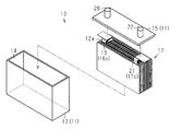
- the disassembled perspective view of an electrical storage apparatus The disassembled perspective view of an electrode assembly.
- the power storage device 10 of the present embodiment is a lithium ion secondary battery, but may be, for example, a lithium ion capacitor.
- the power storage device 10 may be for on-vehicle use, such as a passenger car or an industrial vehicle, or may be for stationary use.
- the storage device 10 includes a case 11 and an electrode assembly 12 housed in the case 11.
- the case 11 has a bottomed cylindrical case main body 13 having an opening 14 and a plate-like lid 15 closing the opening 14.
- the case body 13 and the lid 15 are made of metal such as stainless steel or aluminum, for example.
- an electrolytic solution is accommodated in the case 11 as an electrolyte (not shown).
- the electrode assembly 12 has a positive electrode 16 and a negative electrode 17, and in the electrode assembly 12, the positive electrode 16 and the negative electrode 17 are mutually insulated. Layered. That is, the electrode assembly 12 has a stacked structure in which the positive electrode 16 and the negative electrode 17 are alternately stacked. The electrode assembly 12 may be wound in a state in which the strip-shaped positive electrode 16 and the strip-shaped negative electrode 17 are mutually insulated.
- the electrode assembly 12 includes a porous separator 18 which is interposed between the positive electrode 16 and the negative electrode 17 and insulates the positive electrode 16 and the negative electrode 17 from each other.
- the separator 18 is made of, for example, a resin material such as polypropylene or polyethylene, and has a fine pore structure so that lithium (lithium ion) can pass through with charge and discharge.
- the positive electrode 16 includes a positive electrode metal foil 16a, a positive electrode active material layer 16b covering at least a part of the positive electrode metal foil 16a, and a positive electrode current collecting tab 16c projecting from the edge in the surface direction of the positive electrode metal foil 16a.
- the positive electrode metal foil 16a is, for example, an aluminum foil or an aluminum alloy foil.
- the positive electrode active material layer 16 b contains a positive electrode active material (hereinafter, referred to as a positive electrode active material), a binder, and a conductive auxiliary agent, if necessary.
- Examples of Li x Ni a Co b Mn c O 2 include LiNi 1/3 Co 1/3 Mn 1/3 O 2 and LiNi 0.5 Co 0.2 Mn 0.3 O 2 .
- the positive electrode active material preferably contains nickel.
- the binder for the positive electrode is, for example, polyvinylidene fluoride (PVDF), polytetrafluoroethylene, styrene butadiene rubber or the like.
- PVDF polyvinylidene fluoride
- the conductive aid for the positive electrode is, for example, acetylene black, ketjen black, flaky graphite and the like.
- the positive electrode active material layer 16b is formed by applying a positive electrode active material, a binder, a conductive auxiliary agent, and a paste-like mixture obtained by kneading N-methyl-2-pyrrolidone (NMP) as a solvent to the positive electrode metal foil 16a. It is formed dry. For this reason, the positive electrode active material layer 16b may contain a slight amount of NMP.
- NMP N-methyl-2-pyrrolidone
- the negative electrode 17 includes a negative electrode metal foil 17a, a negative electrode active material layer 17b covering at least a part of the negative electrode metal foil 17a, and a negative electrode current collector tab 17c projecting from the edge in the surface direction of the negative metal foil 17a.
- the negative electrode metal foil 17a is, for example, a copper foil or a copper alloy foil.
- the negative electrode active material layer 17 b contains an active material for the negative electrode (hereinafter referred to as a negative electrode active material), a binder, and, if necessary, a conductive auxiliary.
- the negative electrode active material is a material capable of inserting and extracting lithium (lithium ion).
- the negative electrode active material is, for example, a carbon material such as graphite (natural graphite, artificial graphite), cokes, graphites, glassy carbons, an organic polymer compound fired body, carbon fiber, activated carbon, carbon blacks and the like.
- the binder for the negative electrode is, for example, PVDF, polytetrafluoroethylene, styrene butadiene rubber or the like. One type of binder may be used for the negative electrode, or two or more types may be used in combination.
- the conductive aid for the negative electrode is, for example, acetylene black or ketjen black.
- the negative electrode active material layer 17 b is formed by applying a negative electrode active material, a binder, a conductive additive, and a paste-like mixture obtained by kneading water as a solvent onto the negative electrode metal foil 17 a and then drying it.
- the negative electrode 17 may have an insulating heat-resistant layer 17 d covering at least a part of the surface of the negative electrode active material layer 17 b.
- the heat-resistant layer 17d has a fine pore structure so that lithium (lithium ions) can pass through with charge and discharge.
- the heat-resistant layer 17 d contains insulating particles and a binder.
- the insulating particles used for the heat-resistant layer 17 d are, for example, ceramic particles such as aluminum oxide (alumina), silica, and titania. The particle size of the ceramic particles can be 0.2 to 2.0 ⁇ m.
- the binder is, for example, polyvinylidene fluoride (PVDF), a fluorine-containing resin such as polytetrafluoroethylene or fluororubber, a thermoplastic resin such as polypropylene or polyethylene, an imide resin such as polyimide or polyamideimide, an alkoxysilyl group-containing resin And synthetic rubbers such as styrene butadiene rubber, carboxymethyl cellulose and the like.
- the amount of the binder can be, for example, 1 to 30 parts by mass with respect to 100 parts by mass of the ceramic particles.
- the thickness of the heat-resistant layer 17d can be, for example, 0.5 to 30 ⁇ m.
- the heat-resistant layer 17d is formed by applying a paste-like mixture obtained by kneading insulating particles, a binder, and NMP as a solvent on the surface of the negative electrode active material layer 17b formed on the negative electrode metal foil 17a and then drying it. ing. Therefore, when the negative electrode active material layer 17b is covered with the heat-resistant layer 17d, the negative electrode active material layer 17b and the heat-resistant layer 17d may contain a slight amount of NMP.
- the electrode assembly 12 has a positive electrode current collecting tab group 19 which protrudes from the surface 12 a facing the lid 15 and in which a plurality of positive electrode current collecting tabs 16 c are layered.
- the positive electrode current collection tab group 19 is connected to a positive electrode terminal 20 as an electrode terminal for exchanging electricity with the electrode assembly 12.
- the positive electrode terminal 20 is fixed to the lid 15 and protrudes outside the case 11.
- the electrode assembly 12 has a negative electrode current collection tab group 21 which protrudes from the facing surface 12 a and in which a plurality of negative electrode current collection tabs 17 c are layered.
- the negative electrode current collecting tab group 21 is connected to a negative electrode terminal 22 as an electrode terminal for transferring electricity with the electrode assembly 12.
- the negative electrode terminal 22 is fixed to the lid 15 and protrudes outside the case 11.
- the ratio of the specific surface area S1 of the positive electrode active material contained in the positive electrode active material layer 16b to the specific surface area S2 of the negative electrode active material contained in the negative electrode active material layer 17b Is 0.05 or more and 0.3 or less.
- the "specific surface area” in the present specification means a specific surface area (BET specific surface area) measured by a gas adsorption method using nitrogen gas.
- the ratio of the specific surface area S1 of the positive electrode active material to the specific surface area S2 of the negative electrode active material is 0.3 or less, the reaction area in the positive electrode active material is sufficiently small compared to the reaction area in the negative electrode active material Can.
- the reaction field is biased to the positive electrode 16 and the resistance of the positive electrode 16 accompanying the side reaction is
- the amount of increase can be made larger than the amount of increase in resistance at the negative electrode 17.
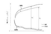
- FIG. 3 the state of the potential change of each of the electrodes 16 and 17 on the basis of metallic lithium (vsLi / Li +) accompanying charging is schematically shown in the initial stage (indicated by a broken line) and after deterioration (indicated by a solid line). It shows.
- the amount of increase in resistance in positive electrode 16 due to repeated charging and discharging can be made larger than the amount of increase in resistance in negative electrode 17, voltage V between terminals 20 and 22 (potential difference between electrodes 16 and 17 It is possible to suppress that the negative electrode potential becomes 0 V or less based on metal lithium when the reference voltage Va becomes the reference voltage Va). That is, the potential difference when the negative electrode potential does not fall below 0 V on the basis of metallic lithium can be suppressed from becoming smaller as the charge and discharge are repeated.
- metal lithium may be deposited, which may adversely affect the power storage device 10.
- the power storage device 10 of the present embodiment even when charging is performed so that the voltage between the terminals 20 and 22 becomes the reference voltage Va, precipitation of metal lithium can be suppressed.
- the ratio (C1 / C2) of the content C1 of NMP in the positive electrode 16 to the content C2 of NMP in the negative electrode 17 is preferably, for example, 1 or more.
- the content C1 of NMP in the positive electrode 16 indicates the ratio of the weight of NMP to the weight of the positive electrode active material layer 16b
- the content C2 of NMP in the negative electrode 17 is the ratio of the negative electrode active material layer 17b and the heat-resistant layer 17d.
- the ratio of the weight of NMP to the weight is shown.
- the NMP content is obtained by extracting NMP from the sample with a solvent (such as diethyl carbonate) and analyzing the extract by gas chromatography to calculate the weight W1 of NMP in the extract and the weight W2 of the sample It can be calculated as the ratio of (W1 / W2).
- the effects of the present embodiment will be described.
- (1) by setting the ratio of the specific surface area S1 of the positive electrode active material to the specific surface area S2 of the negative electrode active material to 0.05 or more and 0.3 or less, the negative electrode potential is 0 V based on metal lithium. It is possible to suppress a reduction in the potential difference between the electrodes 16 and 17 when the current does not fall below. Therefore, the decrease in capacity can be suppressed.
- the resistance in the positive electrode 16 can be made larger than the increase in resistance at the negative electrode 17. Therefore, it is possible to suppress a reduction in the potential difference between the electrodes 16 and 17 when the negative electrode potential does not fall below 0 V based on metal lithium.
- CMC carboxymethyl cellulose
- SBR styrene butadiene rubber
- a mixture for a negative electrode was applied to a copper foil having a thickness of 10 ⁇ m, and then dried and pressed to form a negative electrode active material layer.
- the solid content ratio of the mixture for negative electrodes is as follows.
- the density of the negative electrode active material layer is 1.40 g / cm 3 , and the porosity is 35%.
- the mixture is applied to the surface of the negative electrode active material layer and then dried. Heat resistant layer was formed. Thereafter, it was cut into a sheet to obtain a negative electrode.
- the ratio (C1 / C2) of the content C1 (ppm) of NMP in the positive electrode active material layer to the content C2 (ppm) of NMP in the negative electrode active material layer and the heat-resistant layer is the produced positive electrode and negative electrode It dried so that it might be set to 1.1, and adjusted content of NMP in each electrode.
- the content C1 of NMP in the positive electrode active material layer (positive electrode NMP content C1) was 92 ppm
- the content C2 of NMP in the negative electrode active material layer (negative electrode NMP content C2) was 86 ppm.
- a reference (reference) electrode is placed to prepare a cell for evaluation, and this is used as the ratio of the specific surface area S1 of the positive electrode active material to the negative electrode active material. It was set as the sample a1 whose ratio (S1 / S2) with surface area S2 is 0.03.
- a reference electrode LiFePO 4 previously adjusted to a potential of 3.43 V with respect to metallic lithium was used.
- sample a2 A positive electrode active material having a specific surface area S1 of 0.24 m 2 / g for the positive electrode and a negative electrode active material having a specific surface area S2 of 4.42 m 2 / g for the negative electrode
- the sample a2 whose ratio (S1 / S2) to the specific surface area S2 of the substance is 0.05 was produced.
- the preparation procedure is the same as that of the sample a1, and thus detailed description will be omitted.
- the positive electrode NMP content C1 was 95 ppm
- the negative electrode NMP content C2 was 86 ppm.
- sample a3 A positive electrode active material having a specific surface area S1 of 0.50 m 2 / g for the positive electrode and a negative electrode active material having a specific surface area S2 of 3.38 m 2 / g for the negative electrode
- the sample a3 whose ratio (S1 / S2) to the specific surface area S2 of the substance is 0.15 was produced.
- the positive electrode NMP content C1 was 115 ppm
- the negative electrode NMP content C2 was 102 ppm.
- sample a4 Using a positive electrode active material having a specific surface area S1 of 0.69 m 2 / g for the positive electrode, and using a negative electrode active material having a specific surface area S2 of 2.80 m 2 / g for the negative electrode The sample a4 whose ratio (S1 / S2) to the specific surface area S2 of a substance is 0.25 was produced.
- the positive electrode NMP content C1 was 137 ppm
- the negative electrode NMP content C2 was 125 ppm.
- the specific surface area S1 is positive electrode using the positive electrode active material of 0.69 m 2 / g, the negative electrode active material with a specific surface area S1 and the negative electrode active positive electrode active material having a specific surface area S2 to the negative electrode is 2.3 m 2 / g
- the sample a5 whose ratio (S1 / S2) with the specific surface area S2 of a substance is 0.3 was produced.
- the positive electrode NMP content C1 was 137 ppm
- the negative electrode NMP content C2 was 125 ppm.
- sample a6 Using a positive electrode active material having a specific surface area S1 of 0.69 m 2 / g for the positive electrode and using a negative electrode active material having a specific surface area S2 of 2.12 m 2 / g for the negative electrode The sample a6 whose ratio (S1 / S2) with specific surface area S2 of a substance is 0.33 was produced.
- the positive electrode NMP content C1 was 137 ppm
- the negative electrode NMP content C2 was 125 ppm.
- the specific surface area S1 is positive electrode using the positive electrode active material of 0.69 m 2 / g, the negative electrode active material with a specific surface area S1 and the negative electrode active positive electrode active material having a specific surface area S2 to the negative electrode is 1.74 2 / g
- the sample a7 whose ratio (S1 / S2) with the specific surface area S2 of a substance is 0.40 was produced.
- the positive electrode NMP content C1 was 137 ppm
- the negative electrode NMP content C2 was 125 ppm.
- the mixture was kneaded to obtain a paste-like mixture for a positive electrode.
- the mixture for the positive electrode was applied to an aluminum foil having a thickness of 15 ⁇ m, dried and pressed to form a positive electrode active material layer, and then cut into a sheet to obtain a positive electrode.
- CMC carboxymethyl cellulose
- SBR styrene butadiene rubber
- Each electrode is dried so that the content C1 of NMP in the positive electrode active material layer is 146 ppm and the content C2 of NMP in the negative electrode active material layer and the heat-resistant layer is 58 ppm, and the ratio of the content C1 to C2 of NMP (C1 It adjusted so that / C2) might be set to 2.5.
- a reference (reference) electrode was placed in a state in which a separator was interposed between the manufactured positive electrode and the negative electrode, and a cell for evaluation was manufactured.
- LiFePO 4 previously adjusted to a potential of 3.43 V with respect to metallic lithium was used. Thereafter, it was stored for 100 days in a 60 ° C. environment for aging to obtain a sample b1.
- Example b2 Each electrode is dried so that the content C1 of NMP in the positive electrode active material layer is 95 ppm and the content C2 of NMP in the negative electrode active material layer and the heat-resistant layer is 86 ppm, and the ratio of the content C1 to C2 of NMP (C1
- the sample b2 was prepared by adjusting / C2) to be 1.1.
- the ratio (C1 / C2) of the contents C1 and C2 is different from that of the sample b1, the preparation procedure is the same as that of the sample b1 and thus the detailed description is omitted.
- Example b3 Each electrode is dried so that the content C1 of NMP in the positive electrode active material layer is 67 ppm and the content C2 of NMP in the negative electrode active material layer and the heat-resistant layer is 167 ppm, and the ratio of the content C1 to C2 of NMP (C1 The sample b3 was prepared by adjusting / C2) to be 0.4.
- Example b4 Each electrode is dried so that the content C1 of NMP in the positive electrode active material layer is 52 ppm and the content C2 of NMP in the negative electrode active material layer and the heat resistant layer is 260 ppm, and the ratio of the content C1 to C2 of NMP (C1 The sample b4 was manufactured by adjusting so that / C2) was 0.2.
- the embodiment is not limited to the above, and may be embodied as follows, for example.
- a heat-resistant layer may be provided on the surface of the separator 18 facing the negative electrode active material layer 17b, or a sheet-like heat resistant material. It may be provided between the negative electrode 17 and the separator 18.
- a sheet-like heat-resistant material may be provided between the negative electrode 17 and the separator 18 and between the positive electrode 16 and the separator 18, respectively.
Landscapes
- Engineering & Computer Science (AREA)
- Chemical & Material Sciences (AREA)
- Manufacturing & Machinery (AREA)
- Chemical Kinetics & Catalysis (AREA)
- Electrochemistry (AREA)
- General Chemical & Material Sciences (AREA)
- Materials Engineering (AREA)
- Battery Electrode And Active Subsutance (AREA)
- Secondary Cells (AREA)
- Cell Electrode Carriers And Collectors (AREA)
Abstract
正極電極と負極電極とが相互に絶縁された状態で層状に重なっている電極組立体(12)と、電極組立体(12)を収容しているケース(11)と、ケース(11)の外部に突出し、且つ電極組立体(12)と電気的に接続されている端子(20,22)と、を備え、正極電極は、金属箔と、該金属箔の少なくとも一部を覆っている正極活物質層とを有し、正極活物質層には正極活物質を含んでおり、負極電極は、金属箔と、該金属箔の少なくとも一部を覆っている負極活物質層とを有しており、負極活物質層には負極活物質を含んでおり、正極活物質の比表面積(S1)と負極活物質の比表面積(S2)との比(S1/S2)が0.05以上0.3以下である。
Description
この発明は、蓄電装置に関する。
従来から、EV(Electric Vehicle)やPHV(Plug in Hybrid Vehicle)などの車両には、電動機などへの供給電力を蓄える蓄電装置として、例えばリチウムイオン二次電池などが搭載されている。このような蓄電装置は、例えば特許文献1に記載されているように、正極活物質層を有する正極電極と、負極活物質層を有する負極電極とを備えている。そして、特許文献1では、粒径や比表面積を規定することにより、電極製造時における取り扱いが容易なリチウムチタン複合酸化物を提供しようとしている。
ところで、蓄電装置の容量は、正極活物質及び負極活物質の物性のバランスを調節することによっても確保できると考えられ、充放電の繰り返しに伴う容量の低下を抑制することが期待されている。
この発明は、このような従来の技術に存在する問題点に着目してなされたものであり、その目的は、容量が低下することを抑制できる蓄電装置を提供することにある。
上記課題を解決する蓄電装置は、正極電極と負極電極とが相互に絶縁された状態で層状に重なっている電極組立体と、前記電極組立体を収容しているケースと、前記ケースの外部に突出し、且つ前記電極組立体と電気的に接続されている電極端子と、を備え、前記正極電極は、金属箔と、該金属箔の少なくとも一部を覆っている正極活物質層とを有し、前記正極活物質層には正極活物質を含んでおり、前記負極電極は、金属箔と、該金属箔の少なくとも一部を覆っている負極活物質層とを有しており、前記負極活物質層には負極活物質を含んでおり、前記正極活物質の比表面積S1と前記負極活物質の比表面積S2の比(S1/S2)が0.05以上0.3以下であることを要旨とする。
この構成によれば、正極活物質の比表面積S1と負極活物質の比表面積S2との比を0.3以下とすることで、正極活物質における反応面積を、負極活物質における反応面積と比較して十分に小さく抑えることができる。このため、負極電極における電圧降下量と正極電極における電圧降下量とから、金属リチウム基準で負極電位が0Vを下回らないときの電極間の電位差を大きくできる。また、正極活物質の比表面積S1と負極活物質の比表面積S2との比を0.05以上とすることで、反応場を正極電極に偏らせ、正極電極における抵抗の増加量を、負極電極における抵抗の増加量より大きくできる。このため、蓄電装置の製造後においても、金属リチウム基準で負極電位が0Vを下回らないときの電位差が、充放電に伴って小さくなることを抑制できる。したがって、容量が低下することを抑制できる。
上記蓄電装置において、前記正極電極におけるN-メチル-2-ピロリドンの含有量C1と、前記負極電極におけるN-メチル-2-ピロリドンの含有量C2との比(C1/C2)が1以上であることが好ましい。
この構成によれば、反応場が正極電極に偏るため、正極電極における抵抗の増加量が負極電極における抵抗の増加量よりも大きくなり、蓄電装置の製造後においても、金属リチウム基準で負極電位が0Vを下回らないときの電位差が、充放電に伴って小さくなることをより抑制できる。
上記蓄電装置において、前記蓄電装置はリチウムイオン二次電池であることが好ましい。この構成によれば、リチウムイオン二次電池として、製造時や製造後において、容量が低下することを向上できる。
上記蓄電装置において、前記正極活物質はニッケルを含み、前記負極活物質は炭素材料であることが好ましい。
上記蓄電装置において、前記比表面積S1及び前記比表面積S2はBET比表面積であることが好ましい。
上記蓄電装置において、前記比表面積S1及び前記比表面積S2はBET比表面積であることが好ましい。
本発明によれば、容量が低下することを抑制できる。
以下、本実施形態の蓄電装置について説明する。
図1に示すように、本実施形態の蓄電装置10は、リチウムイオン二次電池であるが、例えばリチウムイオンキャパシタなどであってもよい。また、蓄電装置10は、乗用車や産業用車などの車載用であってもよく、定置用であってもよい。
図1に示すように、本実施形態の蓄電装置10は、リチウムイオン二次電池であるが、例えばリチウムイオンキャパシタなどであってもよい。また、蓄電装置10は、乗用車や産業用車などの車載用であってもよく、定置用であってもよい。
蓄電装置10は、ケース11と、該ケース11に収容されている電極組立体12と、を備えている。ケース11は、開口部14を有する有底筒状のケース本体13と、開口部14を塞ぐ板状の蓋15と、を有する。ケース本体13及び蓋15は、例えばステンレスやアルミニウムなどの金属製である。また、ケース11には、図示しない電解質として、電解液が収容されている。
図2に示すように、電極組立体12は、正極電極16と負極電極17とを有しているとともに、電極組立体12では、正極電極16と負極電極17とが相互に絶縁された状態で層状に重なっている。即ち、電極組立体12は、正極電極16と負極電極17とが交互に積層された積層構造を有している。なお、電極組立体12は、帯状の正極電極16と帯状の負極電極17とが相互に絶縁された状態で捲回されていてもよい。
また、電極組立体12は、正極電極16と負極電極17との間に介在し、正極電極16と負極電極17とを相互に絶縁している多孔質のセパレータ18を備えている。セパレータ18は、例えばポリプロピレンやポリエチレンなどの樹脂材料製であり、充放電に伴ってリチウム(リチウムイオン)が通過可能となるように微細な空孔構造を有している。
正極電極16は、正極金属箔16aと、正極金属箔16aの少なくとも一部を覆っている正極活物質層16bと、縁部から正極金属箔16aの面方向に突出する正極集電タブ16cと、を有する。正極金属箔16aは、例えばアルミニウム箔やアルミニウム合金箔などである。正極活物質層16bは、正極用の活物質(以下、正極活物質という)、バインダ、及び必要な場合に導電助剤を含んでいる。正極活物質は、例えばLiCoO2、LiNiO2、LiMn2O4、LiFePO4、及びLixNiaCobMncO2(0.95<x<1.15,0.35<a<0.65,0.15<b<0.45,0.05<c<0.35,a+b+c=1)などである。LixNiaCobMncO2としては、例えばLiNi1/3Co1/3Mn1/3O2、及びLiNi0.5Co0.2Mn0.3O2などが挙げられる。また、正極活物質は、好ましくはニッケルを含む。
また、正極用のバインダは、例えばポリフッ化ビニリデン(PVDF)、ポリ四フッ化エチレン、スチレンブタジエンゴムなどである。正極用のバインダには、一種類を用いてもよいし、二種類以上を併用してもよい。正極用の導電助剤は、例えばアセチレンブラック、ケッチェンブラック、鱗片状黒鉛などである。
正極活物質層16bは、正極活物質、バインダ、導電助剤、及び溶媒としてのN-メチル-2-ピロリドン(NMP)を混練したペースト状の合剤を、正極金属箔16aに塗布したのちに乾燥して形成されている。このため、正極活物質層16bは、微量のNMPを含有している場合がある。
また、負極電極17は、負極金属箔17aと、負極金属箔17aの少なくとも一部を覆っている負極活物質層17bと、縁部から負極金属箔17aの面方向に突出する負極集電タブ17cと、を有する。負極金属箔17aは、例えば銅箔や銅合金箔などである。負極活物質層17bは、負極用の活物質(以下、負極活物質という)、バインダ、及び必要な場合に導電助剤を含んでいる。
負極活物質は、リチウム(リチウムイオン)を吸蔵及び放出可能な材料である。負極活物質は、例えば黒鉛(天然黒鉛、人造黒鉛)、コークス類、グラファイト類、ガラス状炭素類、有機高分子化合物焼成体、炭素繊維、活性炭素、カーボンブラック類などの炭素材料である。負極用のバインダは、例えばPVDF、ポリ四フッ化エチレン、スチレンブタジエンゴムなどである。負極用のバインダには、一種類を用いてもよいし、二種類以上を併用してもよい。負極用の導電助剤は、例えばアセチレンブラックや、ケッチェンブラックなどである。負極活物質層17bは、負極活物質、バインダ、導電助剤、及び溶媒としての水を混練したペースト状の合剤を、負極金属箔17aに塗布したのちに乾燥して形成されている。
また、負極電極17は、負極活物質層17bの表面の少なくとも一部を覆う絶縁性の耐熱層17dを有していてもよい。耐熱層17dは、充放電に伴ってリチウム(リチウムイオン)が通過可能となるように微細な空孔構造を有している。耐熱層17dは、絶縁性粒子、及びバインダを含んでいる。耐熱層17dに用いられる絶縁性粒子は、例えば酸化アルミニウム(アルミナ)、シリカ、チタニアなどのセラミック粒子である。セラミクス粒子の粒径は、0.2~2.0μmとすることができる。また、バインダは、例えばポリフッ化ビニリデン(PVDF)、ポリテトラフルオロエチレン、フッ素ゴムなどの含フッ素樹脂、ポリプロピレン、ポリエチレンなどの熱可塑性樹脂、ポリイミド、ポリアミドイミドなどのイミド系樹脂、アルコキシシリル基含有樹脂、スチレンブタジエンゴムなどの合成ゴム、カルボキシメチルセルロースなどである。バインダの量は、セラミクス粒子100質量部に対して、例えば、1~30質量部とすることができる。耐熱層17dの厚みは、例えば、0.5~30μmとすることができる。
耐熱層17dは、絶縁性粒子、バインダ、及び溶媒としてのNMPを混練したペースト状の合剤を、負極金属箔17aに形成した負極活物質層17bの表面に塗布したのちに乾燥して形成されている。このため、負極活物質層17bを耐熱層17dで覆う場合、負極活物質層17b及び耐熱層17dは、微量のNMPを含有している場合がある。
図1に示すように、電極組立体12は、蓋15との対向面12aから突出し、複数の正極集電タブ16cが層状に重なった正極集電タブ群19を有する。正極集電タブ群19には、電極組立体12と電気を授受する電極端子としての正極端子20が接続されている。正極端子20は、蓋15に固定されているとともに、ケース11の外部に突出している。また、電極組立体12は、対向面12aから突出し、複数の負極集電タブ17cが層状に重なった負極集電タブ群21を有する。負極集電タブ群21には、電極組立体12と電気を授受する電極端子としての負極端子22が接続されている。負極端子22は、蓋15に固定されているとともに、ケース11の外部に突出している。
そして、本実施形態において、正極活物質層16bに含まれている正極活物質の比表面積S1と、負極活物質層17bに含まれている負極活物質の比表面積S2との比(S1/S2)は、0.05以上0.3以下である。本明細書における「比表面積」は、窒素ガスを用いたガス吸着法により測定した比表面積(BET比表面積)を意味する。
ここで、比表面積が小さいほど活物質における反応面積が小さくなり、電極における電圧降下量(IRドロップ)が大きくなる。正極活物質の比表面積S1と負極活物質の比表面積S2の比を0.3以下とすることで、正極活物質における反応面積を、負極活物質における反応面積と比較して十分に小さく抑えることができる。これにより、正極電極16における電圧降下量と、負極電極17における電圧降下量との関係から、金属リチウム基準で負極電位が0Vを下回らないときの初期の電位差を大きくできる。
また、正極活物質の比表面積S1と負極活物質の比表面積S2との比を0.05以上とすることで、反応場を正極電極16に偏らせ、副反応に伴う正極電極16における抵抗の増加量を、負極電極17における抵抗の増加量より大きくできる。
図3には、充電に伴う金属リチウム基準(vsLi/Li+)での各電極16,17の電位変化の様子を、初期(破線で示す)と、劣化後(実線で示す)とについて模式的に示している。上述のように、充放電を繰り返すことに伴う正極電極16における抵抗の増加量を、負極電極17における抵抗の増加量より大きくできることから、端子20,22間の電圧V(電極16,17の電位差)が基準電圧Vaとなるときの負極電位が金属リチウム基準で0V以下になることを抑制できる。即ち、金属リチウム基準で負極電位が0Vを下回らないときの電位差が、充放電を繰り返すことに伴って小さくなることを抑制できる。
なお、一般に、負極電位が金属リチウム基準で0V以下になると、金属リチウムが析出し、蓄電装置10に悪影響を及ぼす虞がある。本実施形態の蓄電装置10では、端子20,22間の電圧が基準電圧Vaとなるように充電した場合であっても、金属リチウムが析出してしまうことを抑制できる。
また、正極電極16におけるNMPの含有量C1と、負極電極17におけるNMPの含有量C2との比(C1/C2)は、例えば1以上であることが好ましい。このような構成により、充放電時の反応場は、正極電極16に偏ることから、正極電極16での抵抗の増加量が負極電極17での抵抗の増加量よりも大きくなる。したがって、このような構成を採用した場合には、蓄電装置10において金属リチウムが析出することをさらに抑制できる。
なお、正極電極16におけるNMPの含有量C1は、正極活物質層16bの重量に対するNMPの重量の比率を示し、負極電極17におけるNMPの含有量C2は、負極活物質層17b及び耐熱層17dの重量に対するNMPの重量の比率を示す。NMPの含有量は、試料からNMPを溶媒(例えばジエチルカーボネートなど)で抽出するとともに、該抽出液をガスクロマトグラフィーで分析して算出した抽出液中のNMPの重量W1と、試料の重量W2との比(W1/W2)として算出できる。
次に、本実施形態の効果について記載する。
(1)本実施形態によれば、正極活物質の比表面積S1と負極活物質の比表面積S2の比を0.05以上0.3以下とすることで、金属リチウム基準で負極電位が0Vを下回らないときの電極16,17間の電位差が小さくなることを抑制できる。したがって、容量が低下することを抑制できる。
(1)本実施形態によれば、正極活物質の比表面積S1と負極活物質の比表面積S2の比を0.05以上0.3以下とすることで、金属リチウム基準で負極電位が0Vを下回らないときの電極16,17間の電位差が小さくなることを抑制できる。したがって、容量が低下することを抑制できる。
(2)本実施形態によれば、正極電極16におけるNMPの含有量C1と負極電極17におけるNMPの含有量C2との比(C1/C2)を1以上とすることで、正極電極16における抵抗の増加量を負極電極17における抵抗の増加量よりも大きくできる。したがって、金属リチウム基準で負極電位が0Vを下回らないときの電極16,17間の電位差が小さくなることを抑制できる。
(3)本実施形態によれば、リチウムイオン二次電池として、製造時や製造後において、容量が低下することを向上できる。
以下、上記実施形態をさらに具体化した実施例について説明する。
[試験1]
<試料の作製>
(試料a1)
[正極電極の作製]
正極活物質としてLiNi0.5Co0.2Mn0.3O2(比表面積S1=0.15m2/g)と、導電助剤として鱗片状黒鉛と、バインダとしてPVDFと、溶媒としてNMPとを混練し、ペースト状である正極用の合剤を得た。続けて、厚さ15μmのアルミニウム箔に対して正極用の合剤を塗布し、さらに乾燥及びプレスして正極活物質層を形成した後にシート状に切り出して正極電極を得た。なお、正極用の合剤の固形分比率は、次のとおりである。
[試験1]
<試料の作製>
(試料a1)
[正極電極の作製]
正極活物質としてLiNi0.5Co0.2Mn0.3O2(比表面積S1=0.15m2/g)と、導電助剤として鱗片状黒鉛と、バインダとしてPVDFと、溶媒としてNMPとを混練し、ペースト状である正極用の合剤を得た。続けて、厚さ15μmのアルミニウム箔に対して正極用の合剤を塗布し、さらに乾燥及びプレスして正極活物質層を形成した後にシート状に切り出して正極電極を得た。なお、正極用の合剤の固形分比率は、次のとおりである。
正極活物質:導電助剤:PVDF=94:3:3
また、正極活物質層の密度は3.13g/cm3、空隙率は20%である。
[負極電極の作製]
負極活物質として黒鉛(比表面積S2=4.42m2/g)と、増粘剤としてカルボキシメチルセルロース(CMC)と、バインダとしてスチレンブタジエンゴム(SBR)と、溶媒として水とを混練し、ペースト状である負極用の合剤を得た。続けて、厚さ10μmの銅箔に対して負極用の合剤を塗布し、さらに乾燥及びプレスして負極活物質層を形成した。なお、負極用の合剤の固形分比率は、次のとおりである。
また、正極活物質層の密度は3.13g/cm3、空隙率は20%である。
[負極電極の作製]
負極活物質として黒鉛(比表面積S2=4.42m2/g)と、増粘剤としてカルボキシメチルセルロース(CMC)と、バインダとしてスチレンブタジエンゴム(SBR)と、溶媒として水とを混練し、ペースト状である負極用の合剤を得た。続けて、厚さ10μmの銅箔に対して負極用の合剤を塗布し、さらに乾燥及びプレスして負極活物質層を形成した。なお、負極用の合剤の固形分比率は、次のとおりである。
負極活物質:増粘剤:バインダ=98:1:1
また、負極活物質層の密度は1.40g/cm3、空隙率は35%である。
次に、絶縁性粒子として酸化アルミニウムと、バインダとしてPVDFと、溶媒としてNMPとを混練してペースト状の合剤を得るとともに、該合剤を負極活物質層の表面に塗布し、さらに乾燥させて耐熱層を形成した。その後、シート状に切り出して負極電極を得た。
また、負極活物質層の密度は1.40g/cm3、空隙率は35%である。
次に、絶縁性粒子として酸化アルミニウムと、バインダとしてPVDFと、溶媒としてNMPとを混練してペースト状の合剤を得るとともに、該合剤を負極活物質層の表面に塗布し、さらに乾燥させて耐熱層を形成した。その後、シート状に切り出して負極電極を得た。
[評価用セルの作製]
作製した正極電極と負極電極とについて、正極活物質層におけるNMPの含有量C1(ppm)と、負極活物質層及び耐熱層におけるNMPの含有量C2(ppm)との比(C1/C2)が1.1となるように乾燥させ、各電極におけるNMPの含有量を調整した。なお、試料a1では、正極活物質層におけるNMPの含有量C1(正極NMP含有量C1)は92ppm、負極活物質層におけるNMPの含有量C2(負極NMP含有量C2)は86ppmであった。
作製した正極電極と負極電極とについて、正極活物質層におけるNMPの含有量C1(ppm)と、負極活物質層及び耐熱層におけるNMPの含有量C2(ppm)との比(C1/C2)が1.1となるように乾燥させ、各電極におけるNMPの含有量を調整した。なお、試料a1では、正極活物質層におけるNMPの含有量C1(正極NMP含有量C1)は92ppm、負極活物質層におけるNMPの含有量C2(負極NMP含有量C2)は86ppmであった。
次に、正極電極と負極電極との間にセパレータを介在させた状態で基準(参照)電極を設置して評価用セルを作製し、これを正極活物質の比表面積S1と負極活物質の比表面積S2との比(S1/S2)が0.03である試料a1とした。基準電極としては、予め金属リチウム基準で3.43Vの電位に調整したLiFePO4を用いた。
(試料a2)
正極電極に比表面積S1が0.24m2/gの正極活物質を用い、負極電極に比表面積S2が4.42m2/gの負極活物質を用い、正極活物質の比表面積S1と負極活物質の比表面積S2との比(S1/S2)が0.05である試料a2を作製した。なお、試料a2~a7では、正極活物質及び負極活物質の比表面積が試料a1と異なるものの、作製手順は試料a1と同様であるので詳細な説明を省略する。試料a2では、正極NMP含有量C1は95ppm、負極NMP含有量C2は86ppmであった。
正極電極に比表面積S1が0.24m2/gの正極活物質を用い、負極電極に比表面積S2が4.42m2/gの負極活物質を用い、正極活物質の比表面積S1と負極活物質の比表面積S2との比(S1/S2)が0.05である試料a2を作製した。なお、試料a2~a7では、正極活物質及び負極活物質の比表面積が試料a1と異なるものの、作製手順は試料a1と同様であるので詳細な説明を省略する。試料a2では、正極NMP含有量C1は95ppm、負極NMP含有量C2は86ppmであった。
(試料a3)
正極電極に比表面積S1が0.50m2/gの正極活物質を用い、負極電極に比表面積S2が3.38m2/gの負極活物質を用い、正極活物質の比表面積S1と負極活物質の比表面積S2との比(S1/S2)が0.15である試料a3を作製した。試料a3では、正極NMP含有量C1は115ppm、負極NMP含有量C2は102ppmであった。
正極電極に比表面積S1が0.50m2/gの正極活物質を用い、負極電極に比表面積S2が3.38m2/gの負極活物質を用い、正極活物質の比表面積S1と負極活物質の比表面積S2との比(S1/S2)が0.15である試料a3を作製した。試料a3では、正極NMP含有量C1は115ppm、負極NMP含有量C2は102ppmであった。
(試料a4)
正極電極に比表面積S1が0.69m2/gの正極活物質を用い、負極電極に比表面積S2が2.80m2/gの負極活物質を用い、正極活物質の比表面積S1と負極活物質の比表面積S2との比(S1/S2)が0.25である試料a4を作製した。試料a4では、正極NMP含有量C1は137ppm、負極NMP含有量C2は125ppmであった。
正極電極に比表面積S1が0.69m2/gの正極活物質を用い、負極電極に比表面積S2が2.80m2/gの負極活物質を用い、正極活物質の比表面積S1と負極活物質の比表面積S2との比(S1/S2)が0.25である試料a4を作製した。試料a4では、正極NMP含有量C1は137ppm、負極NMP含有量C2は125ppmであった。
(試料a5)
正極電極に比表面積S1が0.69m2/gの正極活物質を用い、負極電極に比表面積S2が2.3m2/gの負極活物質を用い、正極活物質の比表面積S1と負極活物質の比表面積S2との比(S1/S2)が0.3である試料a5を作製した。試料a5では、正極NMP含有量C1は137ppm、負極NMP含有量C2は125ppmであった。
正極電極に比表面積S1が0.69m2/gの正極活物質を用い、負極電極に比表面積S2が2.3m2/gの負極活物質を用い、正極活物質の比表面積S1と負極活物質の比表面積S2との比(S1/S2)が0.3である試料a5を作製した。試料a5では、正極NMP含有量C1は137ppm、負極NMP含有量C2は125ppmであった。
(試料a6)
正極電極に比表面積S1が0.69m2/gの正極活物質を用い、負極電極に比表面積S2が2.12m2/gの負極活物質を用い、正極活物質の比表面積S1と負極活物質の比表面積S2との比(S1/S2)が0.33である試料a6を作製した。試料a6では、正極NMP含有量C1は137ppm、負極NMP含有量C2は125ppmであった。
正極電極に比表面積S1が0.69m2/gの正極活物質を用い、負極電極に比表面積S2が2.12m2/gの負極活物質を用い、正極活物質の比表面積S1と負極活物質の比表面積S2との比(S1/S2)が0.33である試料a6を作製した。試料a6では、正極NMP含有量C1は137ppm、負極NMP含有量C2は125ppmであった。
(試料a7)
正極電極に比表面積S1が0.69m2/gの正極活物質を用い、負極電極に比表面積S2が1.74m2/gの負極活物質を用い、正極活物質の比表面積S1と負極活物質の比表面積S2との比(S1/S2)が0.40である試料a7を作製した。試料a7では、正極NMP含有量C1は137ppm、負極NMP含有量C2は125ppmであった。
正極電極に比表面積S1が0.69m2/gの正極活物質を用い、負極電極に比表面積S2が1.74m2/gの負極活物質を用い、正極活物質の比表面積S1と負極活物質の比表面積S2との比(S1/S2)が0.40である試料a7を作製した。試料a7では、正極NMP含有量C1は137ppm、負極NMP含有量C2は125ppmであった。
<電位の測定(1)>
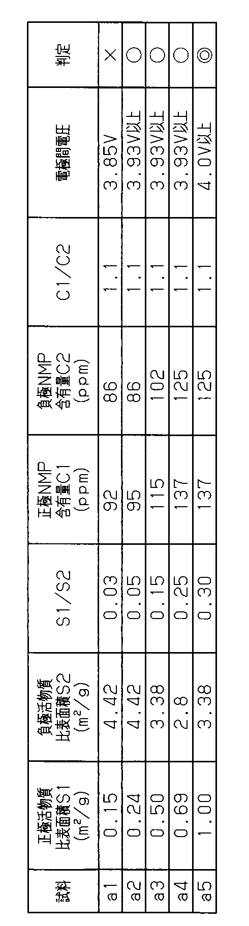
作製した試料a1~a7について、25℃の環境温度のもと、1Cの電流レートによる充電を行うとともに、負極電位が金属リチウム基準で0Vを下回るときの電極間電圧を測定した。その結果を表1に示す。なお、負極電位が金属リチウム基準で0Vを下回るときの電極間電圧(負極電位が0Vとなるセル電圧)が基準電圧Va(ここでは3.93Vとした)以上である場合、合格判定とした。
作製した試料a1~a7について、25℃の環境温度のもと、1Cの電流レートによる充電を行うとともに、負極電位が金属リチウム基準で0Vを下回るときの電極間電圧を測定した。その結果を表1に示す。なお、負極電位が金属リチウム基準で0Vを下回るときの電極間電圧(負極電位が0Vとなるセル電圧)が基準電圧Va(ここでは3.93Vとした)以上である場合、合格判定とした。

<電位の測定(2)>
次に、合格判定となった試料a1~a5を60℃の環境下で100日にわたって保存してエイジングを行ったのち、「電位の測定(1)」と同様にして、負極電位が金属リチウム基準で0Vを下回るときの電極間電圧を測定した。その結果を表2に示す。
次に、合格判定となった試料a1~a5を60℃の環境下で100日にわたって保存してエイジングを行ったのち、「電位の測定(1)」と同様にして、負極電位が金属リチウム基準で0Vを下回るときの電極間電圧を測定した。その結果を表2に示す。
[試験2]
<試料の作製>
(試料b1)
[正極電極の作製]
正極活物質としてLiNi0.5Co0.2Mn0.3O2(比表面積S1=0.24m2/g)と、導電助剤として鱗片状黒鉛と、バインダとしてPVDFと、溶媒としてNMPとを混練し、ペースト状である正極用の合剤を得た。続けて、厚さ15μmのアルミニウム箔に対して正極用の合剤を塗布し、さらに乾燥及びプレスして正極活物質層を形成した後にシート状に切り出して正極電極を得た。
[負極電極の作製]
負極活物質として黒鉛(比表面積S2=4.42m2/g)と、増粘剤としてカルボキシメチルセルロース(CMC)と、バインダとしてスチレンブタジエンゴム(SBR)と、溶媒として水とを混練し、ペースト状である負極用の合剤を得た。続けて、厚さ10μmの銅箔に対して負極用の合剤を塗布し、さらに乾燥及びプレスして負極活物質層を形成した。
負極活物質として黒鉛(比表面積S2=4.42m2/g)と、増粘剤としてカルボキシメチルセルロース(CMC)と、バインダとしてスチレンブタジエンゴム(SBR)と、溶媒として水とを混練し、ペースト状である負極用の合剤を得た。続けて、厚さ10μmの銅箔に対して負極用の合剤を塗布し、さらに乾燥及びプレスして負極活物質層を形成した。
次に、絶縁性粒子として酸化アルミニウムと、バインダとしてPVDFと、溶媒としてNMPとを混練してペースト状の合剤を得るとともに、該合剤を負極活物質層の表面に塗布し、さらに乾燥させて耐熱層を形成した。その後、シート状に切り出して負極電極を得た。
[評価用セルの作製]
正極活物質層におけるNMPの含有量C1が146ppmに、負極活物質層及び耐熱層におけるNMPの含有量C2が58ppmとなるように各電極を乾燥させ、NMPの含有量C1,C2の比(C1/C2)が2.5となるように調整した。そして、作製した正極電極と負極電極との間にセパレータを介在させた状態で基準(参照)電極を設置して評価用セルを作製した。基準電極としては、予め金属リチウム基準で3.43Vの電位に調整したLiFePO4を用いた。その後、60℃の環境下で100日にわたって保存してエイジングし、試料b1とした。
正極活物質層におけるNMPの含有量C1が146ppmに、負極活物質層及び耐熱層におけるNMPの含有量C2が58ppmとなるように各電極を乾燥させ、NMPの含有量C1,C2の比(C1/C2)が2.5となるように調整した。そして、作製した正極電極と負極電極との間にセパレータを介在させた状態で基準(参照)電極を設置して評価用セルを作製した。基準電極としては、予め金属リチウム基準で3.43Vの電位に調整したLiFePO4を用いた。その後、60℃の環境下で100日にわたって保存してエイジングし、試料b1とした。
(試料b2)
正極活物質層におけるNMPの含有量C1が95ppmに、負極活物質層及び耐熱層におけるNMPの含有量C2が86ppmとなるように各電極を乾燥させ、NMPの含有量C1,C2の比(C1/C2)が1.1となるように調整し、試料b2を作製した。なお、試料b2~b4では、含有量C1,C2の比(C1/C2)が試料b1と異なるものの、作製手順は試料b1と同様であるので詳細な説明を省略する。
正極活物質層におけるNMPの含有量C1が95ppmに、負極活物質層及び耐熱層におけるNMPの含有量C2が86ppmとなるように各電極を乾燥させ、NMPの含有量C1,C2の比(C1/C2)が1.1となるように調整し、試料b2を作製した。なお、試料b2~b4では、含有量C1,C2の比(C1/C2)が試料b1と異なるものの、作製手順は試料b1と同様であるので詳細な説明を省略する。
(試料b3)
正極活物質層におけるNMPの含有量C1が67ppmに、負極活物質層及び耐熱層におけるNMPの含有量C2が167ppmとなるように各電極を乾燥させ、NMPの含有量C1,C2の比(C1/C2)が0.4となるように調整し、試料b3を作製した。
正極活物質層におけるNMPの含有量C1が67ppmに、負極活物質層及び耐熱層におけるNMPの含有量C2が167ppmとなるように各電極を乾燥させ、NMPの含有量C1,C2の比(C1/C2)が0.4となるように調整し、試料b3を作製した。
(試料b4)
正極活物質層におけるNMPの含有量C1が52ppmに、負極活物質層及び耐熱層におけるNMPの含有量C2が260ppmとなるように各電極を乾燥させ、NMPの含有量C1,C2の比(C1/C2)が0.2となるように調整し、試料b4を作製した。
正極活物質層におけるNMPの含有量C1が52ppmに、負極活物質層及び耐熱層におけるNMPの含有量C2が260ppmとなるように各電極を乾燥させ、NMPの含有量C1,C2の比(C1/C2)が0.2となるように調整し、試料b4を作製した。
<電位の測定>
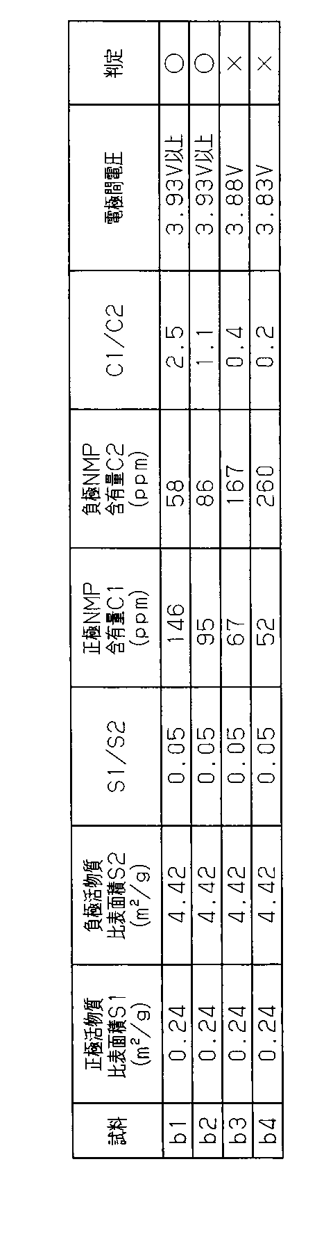
作製した試料b1~b4について、25℃の環境温度のもと、1Cの電流レートによる充電を行うとともに、負極電位が金属リチウム基準で0Vを下回るときの電極間電圧を測定した。その結果を表3に示す。なお、負極電位が金属リチウム基準で0Vを下回るときの電極間電圧が基準電圧Va(ここでは3.93Vとした)以上である場合、合格判定とした。
作製した試料b1~b4について、25℃の環境温度のもと、1Cの電流レートによる充電を行うとともに、負極電位が金属リチウム基準で0Vを下回るときの電極間電圧を測定した。その結果を表3に示す。なお、負極電位が金属リチウム基準で0Vを下回るときの電極間電圧が基準電圧Va(ここでは3.93Vとした)以上である場合、合格判定とした。
実施形態は前記に限定されるものではなく、例えば、次のように具体化してもよい。
負極電極17が負極活物質層17bの表面を覆う耐熱層17dを有する構成に代えて、例えば、セパレータ18の負極活物質層17bと対向する表面に耐熱層を設けたり、シート状の耐熱材を負極電極17とセパレータ18との間に設けたりしてもよい。
負極電極17が負極活物質層17bの表面を覆う耐熱層17dを有する構成に代えて、例えば、セパレータ18の負極活物質層17bと対向する表面に耐熱層を設けたり、シート状の耐熱材を負極電極17とセパレータ18との間に設けたりしてもよい。
シート状の耐熱材を、負極電極17とセパレータ18との間、及び正極電極16とセパレータ18との間にそれぞれ設けてもよい。
10…蓄電装置、11…ケース、12…電極組立体、16…正極電極、16a…正極金属箔(金属箔)、16b…正極活物質層、17…負極電極、17a…負極金属箔(金属箔)、17b…負極活物質層、20…正極端子(電極端子)、22…負極端子(電極端子)。
Claims (5)
- 正極電極と負極電極とが相互に絶縁された状態で層状に重なっている電極組立体と、
前記電極組立体を収容しているケースと、
前記ケースの外部に突出し、且つ前記電極組立体と電気的に接続されている電極端子と、を備え、
前記正極電極は、金属箔と、該金属箔の少なくとも一部を覆っている正極活物質層とを有し、前記正極活物質層には正極活物質を含んでおり、
前記負極電極は、金属箔と、該金属箔の少なくとも一部を覆っている負極活物質層とを有しており、前記負極活物質層には負極活物質を含んでおり、
前記正極活物質の比表面積S1と前記負極活物質の比表面積S2の比(S1/S2)が0.05以上0.3以下である蓄電装置。 - 前記正極電極におけるN-メチル-2-ピロリドンの含有量C1と、前記負極電極におけるN-メチル-2-ピロリドンの含有量C2との比(C1/C2)が1以上である請求項1に記載の蓄電装置。
- 前記蓄電装置はリチウムイオン二次電池である請求項1又は請求項2に記載の蓄電装置。
- 前記正極活物質はニッケルを含み、前記負極活物質は炭素材料である請求項1~請求項3のうちいずれか一項に記載の蓄電装置。
- 前記比表面積S1及び前記比表面積S2はBET比表面積である請求項1~請求項4のうちいずれか一項に記載の蓄電装置。
Priority Applications (1)
| Application Number | Priority Date | Filing Date | Title |
|---|---|---|---|
| JP2016566030A JP6327363B2 (ja) | 2014-12-22 | 2015-11-16 | 蓄電装置 |
Applications Claiming Priority (2)
| Application Number | Priority Date | Filing Date | Title |
|---|---|---|---|
| JP2014-258965 | 2014-12-22 | ||
| JP2014258965 | 2014-12-22 |
Publications (1)
| Publication Number | Publication Date |
|---|---|
| WO2016103971A1 true WO2016103971A1 (ja) | 2016-06-30 |
Family
ID=56150005
Family Applications (1)
| Application Number | Title | Priority Date | Filing Date |
|---|---|---|---|
| PCT/JP2015/082097 Ceased WO2016103971A1 (ja) | 2014-12-22 | 2015-11-16 | 蓄電装置 |
Country Status (2)
| Country | Link |
|---|---|
| JP (1) | JP6327363B2 (ja) |
| WO (1) | WO2016103971A1 (ja) |
Cited By (1)
| Publication number | Priority date | Publication date | Assignee | Title |
|---|---|---|---|---|
| EP4057379A4 (en) * | 2019-11-07 | 2024-10-30 | Murata Manufacturing Co., Ltd. | POSITIVE ELECTRODE FOR SECONDARY BATTERY AND SECONDARY BATTERY |
Citations (8)
| Publication number | Priority date | Publication date | Assignee | Title |
|---|---|---|---|---|
| WO2001091211A1 (en) * | 2000-05-24 | 2001-11-29 | Mitsubishi Cable Industries, Ltd. | Lithium secondary cell and positive electrode active material, positive plate, and method for manufacturing them |
| JP2002203558A (ja) * | 2000-12-28 | 2002-07-19 | Sony Corp | 非水電解質二次電池 |
| JP2006269321A (ja) * | 2005-03-25 | 2006-10-05 | Matsushita Electric Ind Co Ltd | 捲回型非水電解液二次電池 |
| JP2007042525A (ja) * | 2005-08-05 | 2007-02-15 | Hitachi Vehicle Energy Ltd | リチウムイオン電池 |
| JP2007335814A (ja) * | 2006-06-19 | 2007-12-27 | Honda Motor Co Ltd | 蓄電素子 |
| JP2007335319A (ja) * | 2006-06-16 | 2007-12-27 | Sony Corp | 非水電解質二次電池 |
| JP2011222128A (ja) * | 2010-04-02 | 2011-11-04 | Sharp Corp | 二次電池 |
| JP2013065409A (ja) * | 2011-09-15 | 2013-04-11 | Toyota Motor Corp | リチウム二次電池 |
-
2015
- 2015-11-16 JP JP2016566030A patent/JP6327363B2/ja not_active Expired - Fee Related
- 2015-11-16 WO PCT/JP2015/082097 patent/WO2016103971A1/ja not_active Ceased
Patent Citations (8)
| Publication number | Priority date | Publication date | Assignee | Title |
|---|---|---|---|---|
| WO2001091211A1 (en) * | 2000-05-24 | 2001-11-29 | Mitsubishi Cable Industries, Ltd. | Lithium secondary cell and positive electrode active material, positive plate, and method for manufacturing them |
| JP2002203558A (ja) * | 2000-12-28 | 2002-07-19 | Sony Corp | 非水電解質二次電池 |
| JP2006269321A (ja) * | 2005-03-25 | 2006-10-05 | Matsushita Electric Ind Co Ltd | 捲回型非水電解液二次電池 |
| JP2007042525A (ja) * | 2005-08-05 | 2007-02-15 | Hitachi Vehicle Energy Ltd | リチウムイオン電池 |
| JP2007335319A (ja) * | 2006-06-16 | 2007-12-27 | Sony Corp | 非水電解質二次電池 |
| JP2007335814A (ja) * | 2006-06-19 | 2007-12-27 | Honda Motor Co Ltd | 蓄電素子 |
| JP2011222128A (ja) * | 2010-04-02 | 2011-11-04 | Sharp Corp | 二次電池 |
| JP2013065409A (ja) * | 2011-09-15 | 2013-04-11 | Toyota Motor Corp | リチウム二次電池 |
Cited By (1)
| Publication number | Priority date | Publication date | Assignee | Title |
|---|---|---|---|---|
| EP4057379A4 (en) * | 2019-11-07 | 2024-10-30 | Murata Manufacturing Co., Ltd. | POSITIVE ELECTRODE FOR SECONDARY BATTERY AND SECONDARY BATTERY |
Also Published As
| Publication number | Publication date |
|---|---|
| JP6327363B2 (ja) | 2018-05-23 |
| JPWO2016103971A1 (ja) | 2017-09-28 |
Similar Documents
| Publication | Publication Date | Title |
|---|---|---|
| US8125185B2 (en) | Method for charging non-aqueous electrolyte secondary battery | |
| CN103733390A (zh) | 锂离子二次电池 | |
| JP7136017B2 (ja) | 非水電解質二次電池 | |
| JP2015153659A (ja) | 非水電解液二次電池 | |
| JP2021082479A (ja) | 非水電解液二次電池 | |
| CN107004853A (zh) | 复合阴极和包括复合阴极的锂离子电池组以及复合阴极的制备方法 | |
| JP5741936B2 (ja) | リチウムイオン二次電池 | |
| JP5578370B2 (ja) | 二次電池用電極及びその製造方法 | |
| JP7226314B2 (ja) | 電極、蓄電素子、及び電極の製造方法 | |
| CN103765635A (zh) | 非水电解质二次电池用电极、非水电解质二次电池以及电池包 | |
| JPWO2018043375A1 (ja) | 蓄電素子およびその製造方法 | |
| CN111201638A (zh) | 极板、蓄电元件和极板的制造方法 | |
| JP5626183B2 (ja) | 非水電解液二次電池用の正極導電材ペースト、及び、非水電解液二次電池 | |
| JP6880488B2 (ja) | リチウムイオン二次電池 | |
| JP2019040721A (ja) | リチウムイオン二次電池 | |
| JP2018063872A (ja) | リチウムイオン二次電池 | |
| JP5168535B2 (ja) | リチウム二次電池およびその製造方法 | |
| CN105990549B (zh) | 蓄电元件 | |
| JP6327363B2 (ja) | 蓄電装置 | |
| JP5890715B2 (ja) | 非水電解質二次電池用正極及び非水電解質二次電池 | |
| JP6413752B2 (ja) | 蓄電装置 | |
| CN111029580A (zh) | 二次电池用电极和二次电池 | |
| JP2016136489A (ja) | 正極電極、及びリチウムイオン二次電池 | |
| JP6777059B2 (ja) | 非水電解質二次電池の製造方法 | |
| JP2017111875A (ja) | 非水電解質二次電池 |
Legal Events
| Date | Code | Title | Description |
|---|---|---|---|
| 121 | Ep: the epo has been informed by wipo that ep was designated in this application |
Ref document number: 15872540 Country of ref document: EP Kind code of ref document: A1 |
|
| ENP | Entry into the national phase |
Ref document number: 2016566030 Country of ref document: JP Kind code of ref document: A |
|
| NENP | Non-entry into the national phase |
Ref country code: DE |
|
| 122 | Ep: pct application non-entry in european phase |
Ref document number: 15872540 Country of ref document: EP Kind code of ref document: A1 |