WO2016084423A1 - Zn系めっき鋼板のアーク溶接方法およびアーク溶接継手 - Google Patents
Zn系めっき鋼板のアーク溶接方法およびアーク溶接継手 Download PDFInfo
- Publication number
- WO2016084423A1 WO2016084423A1 PCT/JP2015/071744 JP2015071744W WO2016084423A1 WO 2016084423 A1 WO2016084423 A1 WO 2016084423A1 JP 2015071744 W JP2015071744 W JP 2015071744W WO 2016084423 A1 WO2016084423 A1 WO 2016084423A1
- Authority
- WO
- WIPO (PCT)
- Prior art keywords
- welding
- steel sheet
- plated steel
- arc
- heat input
- Prior art date
Links
- 229910000831 Steel Inorganic materials 0.000 title claims abstract description 64
- 239000010959 steel Substances 0.000 title claims abstract description 64
- 238000000034 method Methods 0.000 title claims abstract description 54
- 238000003466 welding Methods 0.000 claims abstract description 335
- 238000007747 plating Methods 0.000 claims description 20
- 239000012535 impurity Substances 0.000 claims description 3
- 229910052725 zinc Inorganic materials 0.000 claims description 2
- 230000000977 initiatory effect Effects 0.000 abstract 1
- 239000011701 zinc Substances 0.000 description 37
- 239000011324 bead Substances 0.000 description 17
- 239000010410 layer Substances 0.000 description 14
- 229910052751 metal Inorganic materials 0.000 description 14
- 239000002184 metal Substances 0.000 description 14
- 238000012360 testing method Methods 0.000 description 14
- 230000000694 effects Effects 0.000 description 6
- 230000008569 process Effects 0.000 description 6
- 229910018134 Al-Mg Inorganic materials 0.000 description 5
- 229910018467 Al—Mg Inorganic materials 0.000 description 5
- 230000000052 comparative effect Effects 0.000 description 5
- 230000007797 corrosion Effects 0.000 description 5
- 238000005260 corrosion Methods 0.000 description 5
- 238000007598 dipping method Methods 0.000 description 5
- 239000000463 material Substances 0.000 description 5
- 238000007711 solidification Methods 0.000 description 5
- 230000008023 solidification Effects 0.000 description 5
- CURLTUGMZLYLDI-UHFFFAOYSA-N Carbon dioxide Chemical compound O=C=O CURLTUGMZLYLDI-UHFFFAOYSA-N 0.000 description 4
- 230000007423 decrease Effects 0.000 description 4
- 238000001816 cooling Methods 0.000 description 3
- 238000007599 discharging Methods 0.000 description 3
- 238000005259 measurement Methods 0.000 description 3
- 229910000838 Al alloy Inorganic materials 0.000 description 2
- 230000009471 action Effects 0.000 description 2
- 230000015572 biosynthetic process Effects 0.000 description 2
- 238000009835 boiling Methods 0.000 description 2
- 229910002092 carbon dioxide Inorganic materials 0.000 description 2
- 239000001569 carbon dioxide Substances 0.000 description 2
- 230000001771 impaired effect Effects 0.000 description 2
- 238000002844 melting Methods 0.000 description 2
- 230000008018 melting Effects 0.000 description 2
- 239000000047 product Substances 0.000 description 2
- 230000009467 reduction Effects 0.000 description 2
- 229910018464 Al—Mg—Si Inorganic materials 0.000 description 1
- HCHKCACWOHOZIP-UHFFFAOYSA-N Zinc Chemical compound [Zn] HCHKCACWOHOZIP-UHFFFAOYSA-N 0.000 description 1
- 229910001297 Zn alloy Inorganic materials 0.000 description 1
- 229910007570 Zn-Al Inorganic materials 0.000 description 1
- 230000008901 benefit Effects 0.000 description 1
- 230000005540 biological transmission Effects 0.000 description 1
- 230000008859 change Effects 0.000 description 1
- 239000011248 coating agent Substances 0.000 description 1
- 239000011247 coating layer Substances 0.000 description 1
- 238000000576 coating method Methods 0.000 description 1
- 239000013065 commercial product Substances 0.000 description 1
- 238000007796 conventional method Methods 0.000 description 1
- 230000007547 defect Effects 0.000 description 1
- 230000003111 delayed effect Effects 0.000 description 1
- 230000006866 deterioration Effects 0.000 description 1
- 238000003618 dip coating Methods 0.000 description 1
- 238000011156 evaluation Methods 0.000 description 1
- 230000006872 improvement Effects 0.000 description 1
- 238000004519 manufacturing process Methods 0.000 description 1
- 150000002739 metals Chemical class 0.000 description 1
- 239000000203 mixture Substances 0.000 description 1
- 239000011148 porous material Substances 0.000 description 1
- 239000002244 precipitate Substances 0.000 description 1
- 230000002265 prevention Effects 0.000 description 1
- 238000012545 processing Methods 0.000 description 1
- 239000002436 steel type Substances 0.000 description 1
- 239000000126 substance Substances 0.000 description 1
- 230000001629 suppression Effects 0.000 description 1
Images

Classifications
-
- B—PERFORMING OPERATIONS; TRANSPORTING
- B23—MACHINE TOOLS; METAL-WORKING NOT OTHERWISE PROVIDED FOR
- B23K—SOLDERING OR UNSOLDERING; WELDING; CLADDING OR PLATING BY SOLDERING OR WELDING; CUTTING BY APPLYING HEAT LOCALLY, e.g. FLAME CUTTING; WORKING BY LASER BEAM
- B23K9/00—Arc welding or cutting
- B23K9/23—Arc welding or cutting taking account of the properties of the materials to be welded
-
- B—PERFORMING OPERATIONS; TRANSPORTING
- B23—MACHINE TOOLS; METAL-WORKING NOT OTHERWISE PROVIDED FOR
- B23K—SOLDERING OR UNSOLDERING; WELDING; CLADDING OR PLATING BY SOLDERING OR WELDING; CUTTING BY APPLYING HEAT LOCALLY, e.g. FLAME CUTTING; WORKING BY LASER BEAM
- B23K9/00—Arc welding or cutting
- B23K9/02—Seam welding; Backing means; Inserts
- B23K9/032—Seam welding; Backing means; Inserts for three-dimensional seams
-
- B—PERFORMING OPERATIONS; TRANSPORTING
- B23—MACHINE TOOLS; METAL-WORKING NOT OTHERWISE PROVIDED FOR
- B23K—SOLDERING OR UNSOLDERING; WELDING; CLADDING OR PLATING BY SOLDERING OR WELDING; CUTTING BY APPLYING HEAT LOCALLY, e.g. FLAME CUTTING; WORKING BY LASER BEAM
- B23K9/00—Arc welding or cutting
- B23K9/095—Monitoring or automatic control of welding parameters
- B23K9/0953—Monitoring or automatic control of welding parameters using computing means
-
- B—PERFORMING OPERATIONS; TRANSPORTING
- B23—MACHINE TOOLS; METAL-WORKING NOT OTHERWISE PROVIDED FOR
- B23K—SOLDERING OR UNSOLDERING; WELDING; CLADDING OR PLATING BY SOLDERING OR WELDING; CUTTING BY APPLYING HEAT LOCALLY, e.g. FLAME CUTTING; WORKING BY LASER BEAM
- B23K9/00—Arc welding or cutting
- B23K9/095—Monitoring or automatic control of welding parameters
- B23K9/0956—Monitoring or automatic control of welding parameters using sensing means, e.g. optical
-
- C—CHEMISTRY; METALLURGY
- C22—METALLURGY; FERROUS OR NON-FERROUS ALLOYS; TREATMENT OF ALLOYS OR NON-FERROUS METALS
- C22C—ALLOYS
- C22C18/00—Alloys based on zinc
- C22C18/04—Alloys based on zinc with aluminium as the next major constituent
-
- C—CHEMISTRY; METALLURGY
- C23—COATING METALLIC MATERIAL; COATING MATERIAL WITH METALLIC MATERIAL; CHEMICAL SURFACE TREATMENT; DIFFUSION TREATMENT OF METALLIC MATERIAL; COATING BY VACUUM EVAPORATION, BY SPUTTERING, BY ION IMPLANTATION OR BY CHEMICAL VAPOUR DEPOSITION, IN GENERAL; INHIBITING CORROSION OF METALLIC MATERIAL OR INCRUSTATION IN GENERAL
- C23C—COATING METALLIC MATERIAL; COATING MATERIAL WITH METALLIC MATERIAL; SURFACE TREATMENT OF METALLIC MATERIAL BY DIFFUSION INTO THE SURFACE, BY CHEMICAL CONVERSION OR SUBSTITUTION; COATING BY VACUUM EVAPORATION, BY SPUTTERING, BY ION IMPLANTATION OR BY CHEMICAL VAPOUR DEPOSITION, IN GENERAL
- C23C2/00—Hot-dipping or immersion processes for applying the coating material in the molten state without affecting the shape; Apparatus therefor
- C23C2/04—Hot-dipping or immersion processes for applying the coating material in the molten state without affecting the shape; Apparatus therefor characterised by the coating material
- C23C2/06—Zinc or cadmium or alloys based thereon
-
- C—CHEMISTRY; METALLURGY
- C23—COATING METALLIC MATERIAL; COATING MATERIAL WITH METALLIC MATERIAL; CHEMICAL SURFACE TREATMENT; DIFFUSION TREATMENT OF METALLIC MATERIAL; COATING BY VACUUM EVAPORATION, BY SPUTTERING, BY ION IMPLANTATION OR BY CHEMICAL VAPOUR DEPOSITION, IN GENERAL; INHIBITING CORROSION OF METALLIC MATERIAL OR INCRUSTATION IN GENERAL
- C23C—COATING METALLIC MATERIAL; COATING MATERIAL WITH METALLIC MATERIAL; SURFACE TREATMENT OF METALLIC MATERIAL BY DIFFUSION INTO THE SURFACE, BY CHEMICAL CONVERSION OR SUBSTITUTION; COATING BY VACUUM EVAPORATION, BY SPUTTERING, BY ION IMPLANTATION OR BY CHEMICAL VAPOUR DEPOSITION, IN GENERAL
- C23C30/00—Coating with metallic material characterised only by the composition of the metallic material, i.e. not characterised by the coating process
-
- F—MECHANICAL ENGINEERING; LIGHTING; HEATING; WEAPONS; BLASTING
- F16—ENGINEERING ELEMENTS AND UNITS; GENERAL MEASURES FOR PRODUCING AND MAINTAINING EFFECTIVE FUNCTIONING OF MACHINES OR INSTALLATIONS; THERMAL INSULATION IN GENERAL
- F16B—DEVICES FOR FASTENING OR SECURING CONSTRUCTIONAL ELEMENTS OR MACHINE PARTS TOGETHER, e.g. NAILS, BOLTS, CIRCLIPS, CLAMPS, CLIPS OR WEDGES; JOINTS OR JOINTING
- F16B5/00—Joining sheets or plates, e.g. panels, to one another or to strips or bars parallel to them
- F16B5/08—Joining sheets or plates, e.g. panels, to one another or to strips or bars parallel to them by means of welds or the like
-
- B—PERFORMING OPERATIONS; TRANSPORTING
- B23—MACHINE TOOLS; METAL-WORKING NOT OTHERWISE PROVIDED FOR
- B23K—SOLDERING OR UNSOLDERING; WELDING; CLADDING OR PLATING BY SOLDERING OR WELDING; CUTTING BY APPLYING HEAT LOCALLY, e.g. FLAME CUTTING; WORKING BY LASER BEAM
- B23K2101/00—Articles made by soldering, welding or cutting
- B23K2101/18—Sheet panels
-
- B—PERFORMING OPERATIONS; TRANSPORTING
- B23—MACHINE TOOLS; METAL-WORKING NOT OTHERWISE PROVIDED FOR
- B23K—SOLDERING OR UNSOLDERING; WELDING; CLADDING OR PLATING BY SOLDERING OR WELDING; CUTTING BY APPLYING HEAT LOCALLY, e.g. FLAME CUTTING; WORKING BY LASER BEAM
- B23K2101/00—Articles made by soldering, welding or cutting
- B23K2101/34—Coated articles, e.g. plated or painted; Surface treated articles
-
- B—PERFORMING OPERATIONS; TRANSPORTING
- B23—MACHINE TOOLS; METAL-WORKING NOT OTHERWISE PROVIDED FOR
- B23K—SOLDERING OR UNSOLDERING; WELDING; CLADDING OR PLATING BY SOLDERING OR WELDING; CUTTING BY APPLYING HEAT LOCALLY, e.g. FLAME CUTTING; WORKING BY LASER BEAM
- B23K2103/00—Materials to be soldered, welded or cut
- B23K2103/02—Iron or ferrous alloys
- B23K2103/04—Steel or steel alloys
-
- B—PERFORMING OPERATIONS; TRANSPORTING
- B23—MACHINE TOOLS; METAL-WORKING NOT OTHERWISE PROVIDED FOR
- B23K—SOLDERING OR UNSOLDERING; WELDING; CLADDING OR PLATING BY SOLDERING OR WELDING; CUTTING BY APPLYING HEAT LOCALLY, e.g. FLAME CUTTING; WORKING BY LASER BEAM
- B23K2103/00—Materials to be soldered, welded or cut
- B23K2103/08—Non-ferrous metals or alloys
Definitions
- the present invention relates to arc welding of Zn (zinc) plated steel sheet.
- the present invention relates to an arc welding method for forming a good weld joint by suppressing the occurrence of blow holes and the like.
- a Zn-based plated steel sheet obtained by plating a steel sheet with Zn or a Zn alloy is excellent in corrosion resistance, strength, workability, etc., and has a beautiful appearance, and thus is widely used in automobiles, houses, home appliances and the like.
- the Zn-based plated steel sheet that is the material to be welded is heated and joined while supplying a welding wire.
- the Zn-based plated steel sheet is arc welded, the Zn-based plated steel sheet, which is the material to be welded, is heated with an arc.
- Patent Document 1 proposes a method in which a gap of about 0.5 mm is provided between both members to be overlap welded, and the generated gas is allowed to escape to the side opposite to the welded portion (see the lower left column on page 1).
- Patent Document 2 as a conventional example, a convex portion is provided on at least one of the two base materials, and a gap is formed around the welded portion, so that the vaporized low boiling point substance is diffused from the gap to the outside.
- a method of escape has been proposed (see paragraph 0005).
- the present invention suppresses the occurrence of blowholes at the starting end that is a region formed after the start of welding and the terminal end that is a region formed before the end of welding in arc welding of a Zn-based plated steel sheet. It aims at reducing the blowhole occupation rate of the whole welded part.
- the inventors of the present invention installed a gap between plates in a predetermined range when arc welding a Zn-based plated steel sheet, and have welding speed, welding heat input, welding current and As for welding conditions such as welding voltage, welding start conditions and end parts of the welded part are different from those in the central part, and arcing is stopped at the end parts. It has been found that the discharge is promoted and the generation of blowholes and pits can be suppressed, and the present invention has been completed. Specifically, the following are provided according to the present invention.
- the gap between the plates is set in a range of 0.2 to 1.5 mm, and welding means are provided along the overlapped portion where the steel plates are welded.
- Welding is performed, the welding means is moved at a first welding speed from a welding start point, and a first step of performing welding by applying a first welding heat input, and the first step Subsequently, the welding means is moved at a second welding speed, a second step of performing welding by applying a second welding heat input, and following the second step, the welding means is moved.
- a third step of performing welding for 0.1 to 2 seconds at the stop position wherein the first step is such that the first welding speed is less than the second welding speed, And including a welded portion where welding is performed under a condition in which the first welding heat input exceeds the second welding heat input, Serial third step, welding the second lower welding current and welding voltage to the step is performed, an arc welding method of Zn-base plated steel sheet.
- the starting end which is the welded portion after the first step is an area of 10 to 40% of the total weld length
- the end portion which is the welded portion after the third step is The arc welding method for a Zn-based plated steel sheet according to (1) above, which is a region of 10 to 20% of the total welding length.
- welding is performed from a welding start point located inward from one end of the overlapped portion toward the end, and then reversed to Welding is performed from one end to the other end, and the welding toward the one end is such that the welding speed is lower than the welding speed in the second step, and the welding is performed.
- the heat input is performed more than 1.2 times the second welding heat input, and the welding toward the other end is performed at the same welding speed as the second welding speed.
- the present invention is an arc welding method for a Zn-based plated steel sheet according to any one of (1) to (4) above, wherein the blowhole occupancy over the entire welding length is less than 30%.
- the Zn-based plated steel sheet is mass%, Al: 4.0-22.0%, Mg: 0.05-10.0%, Ti: 0-0.10%, B : 0 to 0.05%, Si: 0 to 2.0%, Fe: 0 to 2.5%, and having a hot-dip plated layer composed of the balance Zn and unavoidable impurities (1) to (5)
- the Zn-based plated steel sheet has a plating adhesion amount of 20 to 250 g / m 2 on one side and a thickness of 1.6 to 6.0 mm.
- the arc welding method according to any one of the above.
- the present invention is an arc welded joint formed by the arc welding method according to any one of (1) to (7) above, and the blowhole occupancy over the entire weld length is less than 30%. This is an arc welded joint.
- the present invention in arc welding in which a gap between plates of a Zn-based plated steel sheet is provided, the occurrence of blowholes and pits at the start and end portions is suppressed, and the blowhole occupancy rate of the entire welded portion is reduced. Can do. This prevents a decrease in welding strength and contributes to improving the safety and reliability of the welded portion. In addition, a weld with a good appearance can be obtained.
- the gap between the plates corresponding to the gap between the stacked steel sheets is preferably set in a range of 0.2 mm or more and 1.5 mm or less.
- lap fillet welding is a method in which two steel plates are overlapped and the end of one steel plate is overlapped on the surface of the other steel plate, and fillet arc welding is performed.
- inter-plate gap such a gap between the steel plates is referred to as an “inter-plate gap”.
- the gap between the plates is less than 0.2 mm, it is not enough to suppress the generation of blowholes as the space for discharging the generated gas within the welding time. If it exceeds 1.5 mm, the ratio of the weld bead on the front side decreases as the ratio of the back bead formed as a part of the weld bead overflows from the gap to the back side, which is not preferable in terms of joint strength. . Therefore, in the present invention, 0.2 to 1.5 mm is preferable. More preferably, it is 0.5 to 1.2 mm, and still more preferably 0.7 to 1.0 mm.
- welding is performed by moving a welding means along an overlapped portion where the steel plates are welded, and (i) the welding means is moved from a welding start point at a first welding speed. And (ii) following the first step, the war record welding means is moved at the second welding speed, and the second welding is performed. And (iii) following the second step, the movement of the welding means is stopped and welding is performed for 0.1 to 2 seconds at the stop position. And a third step. In the first step, welding is performed under the condition that the first welding speed is less than the second welding speed and the first welding heat input exceeds the second welding heat input. In the third step, welding is performed at a lower welding current and welding voltage than in the second step.
- the overlapping portions of the steel plates are sequentially arranged along the weld line in the first step, the second step, and the third step (hereinafter referred to as “first step”, “second step”,
- the welded portion is formed through “the third step”.
- the welded region obtained after the first step is hereinafter referred to as a “starting end”, and the welded region obtained after the third step is referred to as a “terminal” in this specification.
- a welded portion region sandwiched between the start end portion and the end portion is referred to as a “central portion”.
- the end portion is a region where a weld is formed by performing welding in the third step after performing welding in the second step.
- Each of these regions can be specified by the weld length.
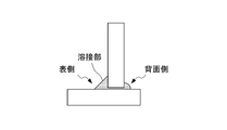
- the overlapped portion welded by the welded members 1 and 2 is divided into a starting end portion 5, a central portion 6, and a terminating end portion 7 between the welding start point and the welding end point. Is done.
- the welded member immediately after the start of welding is being heated at the start end, and the heat supply is terminated at the end, so both welded metals are melted. Is more likely to solidify than the central part.
- the cooling rate of the weld metal is fast, and the molten metal solidifies before the Zn vapor is discharged, so that blow holes and pits are likely to occur. Therefore, in the first step of forming the starting end portion after the start of welding, the first welding speed is lowered and the first welding heat input is increased as compared with the subsequent second step.
- the first welding speed is lower than the second welding speed lower than the second welding speed
- the first welding heat input is the second welding speed. It is preferable to include a welded portion where welding is performed beyond the welding heat input.
- the welding heat input is calculated by the following equation.
- the first welding speed has a portion to be welded at a speed lower than the second welding speed.
- the welding speed is excessively low, it is preferable in terms of work efficiency. Absent.
- the first welding speed is preferably 0.2 to 0.35 m / min, and more preferably 0.2 to 0.3 m / min.
- the 1st welding heat input in a 1st process exceeds 1.2 times the 2nd welding heat input in a 2nd process. More preferably, it is more than 1.3 times, but if it is too large, gas generation will be excessive, so less than 2.0 times is preferable.
- the first welding heat input can be performed at 6350 to 9000 J / cm.
- the second step welding is performed at a second welding speed larger than the first welding speed.
- the second welding heat input is smaller than the first welding heat input.
- the second welding heat input can be performed at 4220 to 6030 J / cm.
- the welding conditions such as the welding current and the welding voltage can be appropriately selected according to the member to be welded, the material of the plating layer, the product shape, and the like.
- the welding current can be 140 to 180 A
- the welding voltage can be 20 to 24V.
- the present invention stops the movement of the welding means in the third step, performs welding for 0.1 to 2 seconds at the stop position, and has welding current and welding lower than those in the second step as the welding conditions.
- Welding with voltage is preferred. It can be carried out with a welding current of 90 to 120 A and a welding voltage of 15 to 18V.
- the third step since welding is continued without moving the welding means, solidification of the weld metal is delayed compared to the case of moving, and the time for discharging Zn vapor can be secured, which is effective in suppressing blowholes. . If the welding time in the third step is too short, the effect is not sufficient.
- welding time becomes long, a weld bead will be formed more than necessary and it is not preferable also in terms of work efficiency. Therefore, a welding time of 0.1 to 2 seconds is preferable.
- welding by the third step is sometimes referred to as “crater processing”.
- the starting end portion which is a welded portion obtained after the first step is 10 to 40% of the total weld length
- the end portion which is a welded portion obtained after the third step is 10 to 20% of the total weld length. It is preferable that this region.
- the start end and the end end are less than 10%, there are few regions contributing to blowhole suppression, and blowhole reduction over the entire weld length is not sufficient.
- the starting end exceeds 40%, the time required for the welding work becomes long, which is not preferable in terms of work efficiency.
- the end portion exceeds 20%, a weld bead is formed more than necessary, which is not preferable in terms of work efficiency.
- the welding length of the terminal portion is preferably formed in a range of less than 10 mm from the terminal end. It is possible to change the welding condition and move to the second step when the start end portion of the predetermined length is formed in the first step. In addition, after the second step, the movement of the welding means is stopped and the welding conditions are changed, the process proceeds to the third step, and the welding can be terminated when a terminal portion having a predetermined length is formed.
- the present invention can use a welding method in which welding is started from one end of the overlapped portion and proceeds in one direction toward the other end.
- the increase in welding heat input increases the time until solidification of the weld metal, which is effective in suppressing blowholes. Therefore, it is preferable that the welding heat input in the first step is a heat amount exceeding 1.2 times the welding heat input in the second step.
- this invention can also set a welding start point in the position away inward from the one edge part of the overlap part.
- welding is performed by moving the welding means from the welding start point toward the end, and then the welding is reversed and welding is performed from the end to the other end (hereinafter referred to as such).
- Such a welding method may be referred to as a “reverse welding method”).
- the welding toward the one end may be performed at a welding speed that is less than the welding speed in the second step and the welding heat input is more than 1.2 times the second welding heat input. preferable. Since the welding toward the other end is then continued to the second step, the same welding speed and welding heat input conditions as those in the second step can be employed.
- the present invention can suppress the occurrence of blowholes and pits in the weld.
- the index can be evaluated by the blowhole occupation rate (%) calculated by the following equation.
- the blow hole occupation ratio (%) the length of the pit is included in the length of the blow hole.
- Blow hole occupancy (%) (total blow hole length) / (weld bead length) x 100
- the blowhole occupancy is preferably less than 30% in each region of the start end, the center, or the end. More preferably, it is less than 15%, More preferably, it is less than 10%.
- the blow hole occupation ratio over the entire weld length is preferably less than 30%, more preferably less than 15%, less than 10%, and further preferably less than 8%. Lower blowhole occupancy contributes to improved weld strength and prevention of deterioration of the appearance.
- Zn-based plated steel sheet Zn-based plated steel sheet
- Zn—Fe, Zn—Al, Zn—Al—Mg, Zn—Al—Mg—Si, etc. can be used as the plating composition of the Zn-based plated steel sheet, and is not particularly limited.
- Al 4.0-22.0%
- Mg 0.05-10.0%
- Ti 0-0.10%
- B 0-0.05%
- Si 0-2.
- a Zn-based plated steel sheet having a hot-dip coating layer containing 0%, Fe: 0 to 2.5%, and the balance Zn and inevitable impurities is preferable.
- Al is an element effective in improving the corrosion resistance of the plated steel sheet and is an element that suppresses the generation of Mg oxide dross in the plating bath. If it is less than 4.0%, these effects are not sufficient.
- the Al content increases, a brittle Fe—Al alloy layer easily grows on the base of the plating layer, which causes a decrease in plating adhesion. Therefore, the Al content is preferably 4.0 to 22.0%.
- Mg exhibits the effect of significantly increasing the corrosion resistance of the plated steel sheet by generating a uniform corrosion product on the surface of the plated layer. If it is less than 0.05%, this action is not sufficient. On the other hand, when the Mg content in the plating bath increases, Mg oxide-based dross is likely to occur, which causes a reduction in the quality of the plating layer. Therefore, the Mg content is preferably 0.05 to 10.0%.
- Ti and B are contained in the hot dipping bath, there is an advantage that the degree of freedom of manufacturing conditions during hot dipping is expanded. For this reason, 1 type or 2 types of Ti and B can be added as needed.
- the amount of addition is more effective if it is 0.0005% or more in the case of Ti and 0.0001% or more in the case of B.
- Ti 0.10% or less and B: 0.05% or less are preferable.
- Si When Si is contained in the hot dipping bath, excessive growth of the Fe—Al alloy layer formed at the interface between the plating original plate surface and the plating layer is suppressed, and the workability of the hot-dip Zn—Al—Mg plated steel sheet is improved. This is advantageous. Therefore, Si can be contained as necessary. In that case, it is more effective to make Si content 0.005% or more. However, since excessive Si content causes an increase in the dross amount in the hot dipping bath, the Si content is preferably 2.0% or less.
- the Fe content in the Zn—Al—Mg plating layer is preferably 2.5% or less.
- the amount of plating adhesion and the plate thickness are not particularly limited.
- the plating adhesion amount per side is preferably 20 to 250 g / m 2 .
- the coating amount is small, it is disadvantageous for maintaining the corrosion resistance and sacrificial anticorrosive action of the plated surface over a long period of time.
- the amount of plating adhesion per side is preferably 20 g / m 2 or more and 250 g / m 2 or less.
- the Zn-based plated steel sheet in the present invention can employ various steel types depending on the application. High tensile steel plates can also be used.
- the plate thickness of the steel plate can be 1.6 to 6.0 mm.
- the welded joint produced by the arc welding method of the present invention preferably has a blowhole occupancy of less than 30% over the entire weld length. Good effects are obtained in terms of welding strength and appearance.
- the present invention is preferably applied to a fillet arc welding method, and gas shielded arc welding such as MAG method and MIG method can be used.
- gas shielded arc welding such as MAG method and MIG method
- a welded joint a lap joint in which a part of a plurality of plate members are overlapped, a T-shaped joint placed so that the end surface of one plate member is substantially orthogonal to the surface of the other plate member, a cross-shaped cross joint, a mother It can be applied to a corner joint or the like that keeps the material in an L shape substantially at a right angle.
- welded members 1 and 2 were prepared using a groove steel (30 mm ⁇ 60 mm) made of a Zn—Al—Mg based steel plate with a thickness of 2.3 mm.
- the used Zn-Al-Mg based steel sheet is composed of Al 6.2%, Mg 2.9%, Ti 0.05%, B 0.01%, Si 0.02%, Fe 0.8% and the balance Zn in mass%.
- the hot-dip plated layer is made of an adhesion amount of 90 g / m 2 .
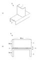
- the end of the first member 1 to be welded is partially crushed in the plate thickness direction by a projection-applying press device on the side that contacts the second member 2 to be welded.
- a projection-applying press device By projecting, two projections 3 were provided.
- the first member to be welded 1 was placed on the flat surface of the second member to be welded 2 to obtain an assembly 8 combined in a T shape. Since the welded members 1 and 2 are in contact with each other via the protrusions 3, they have a gap corresponding to the protrusion height. Thereafter, carbon dioxide arc welding was performed on this assembly to produce a T-shaped joint.
- the dimensions of the T-shaped assembly 8 are as shown in FIG.
- Each of the protrusions 3 was provided at a position 10 mm from both side ends of the member 1 to be welded.
- the protrusion height can be increased by increasing the crushing ratio (crushing ratio) with the protrusion-applying press device.
- the welding conditions were welding current: 160 A, arc voltage: 22.0 V, welding speed: 0.4 m / min, torch angle: 45 °, and the weld bead length was 52 mm.
- Carbon dioxide gas as a shielding gas was supplied at a flow rate of 20 l / min, and a commercial product (MG-50T, manufactured by Kobe Steel) with a diameter of 1.2 mm corresponding to YGW12 of JIS Z 3212 was used as the welding wire.
- Welding was started at one end of the overlapped portion, and welding was performed by moving the welding wire in one direction toward the other end.
- Blow hole occupation ratio (%) (total length of blow holes) / (length of weld bead) ⁇ 100
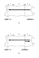
- a region having a length of about 10 mm from both ends of the welded portion is defined as a start end portion and a end portion, respectively, and a region having a length of about 32 mm sandwiched between the start end portion and the end portion.
- the blowhole occupancy in each region was measured, and the results calculated for each region of the start end, center, and end were shown as average values as shown in FIG.
- the blow hole occupancy rate of the example having no protrusion exceeded 30%.
- the average value of blow hole occupancy was 15% or less, and the average value was 10% or less when the gap amount was 1.5 mm.
- blowholes hardly occur at the central part, whereas the blowhole occupancy rate is 30 at the start or end part. % May be exceeded.
- a blow hole does not occur at the start end when the gap amount is 1.2 mm or more, whereas a blow hole occurs at the end portion regardless of the gap amount.
- the gap amount when the gap amount is increased to be, for example, 1.5 mm, the average value of the blowhole occupation ratio is reduced to 10% or less as shown in FIG.
- a part of the weld bead formed on the front side of the welded portion passes from the gap to the back side to form a back bead, and particularly when the gap amount exceeds 1.2 mm, Since the formation of beads becomes remarkable and the bead amount on the front side is reduced and thinned accordingly, the weld strength and appearance may be impaired.
- the occurrence of blow holes cannot be sufficiently suppressed only by increasing the gap amount. It is necessary to find conditions suitable for suppressing the occurrence of blowholes at the start and end portions.
- a T-shaped assembly was prepared by the same procedure as in Test Example 1 with a gap between the plates of 1 mm. Thereafter, arc welding was performed by changing the welding conditions in various ways, and a T-joint specimen was produced.
- welding was performed by moving the welding means in one direction. Welding was started from a position (welding start point) of about 4 mm from one end of the portion against which the members 1 and 2 were abutted, and welding was performed by moving the welding wire in one direction toward the other end. After reaching the vicinity of the welding end point at the other end, the movement of the welding wire was stopped, and welding was completed for a predetermined time at the stop position, and then the welding was ended.
- the starting end of the welded portion corresponds to the welding start point, and the end of the welded portion corresponds to the welding end point.
- the start and end portions are each a region having a length of about 10 mm from both ends of the welded portion, and the central portion sandwiched between the start and end portions is a region having a length of about 32 mm.
- Comparative Example 1 corresponds to the conventional method in which the welding current, the welding voltage, and the welding speed are welded under the same conditions over the entire welding length, and the test shown in FIG. It is one of the examples of 1 mm of gaps between plates of Example 1.
- the blow hole occupancy rate of Comparative Example 1 did not occur in the center as shown in FIG. 3B, but as shown in Table 1, it was 23% at the start end and 38% at the end, both being high. Numerical values are shown. Moreover, the blowhole occupation rate in the welding part full length was 12%.
- the welding speed at the starting end was set to be lower than that at the center, and welding was performed under conditions where the welding heat input exceeded 1.2 times that at the center.
- the central part welding was performed under the same conditions as in Comparative Example 1.
- the crater treatment was performed by setting the welding current, the welding voltage, and the welding speed to conditions lower than those in the central portion, and continuing welding for 1.0 second at the movement stop position of the welding wire.
- the blow hole occupancy ratios of Invention Examples 1 to 3 were 0 to 18% at the start end, 15 to 18% at the end, and 7% or less over the entire length of the weld.
- the solidification time of the weld metal is lengthened and the time for discharging the generated gas is increased, so that the ratio of remaining gas in the melted portion is increased. Reduced. It has been confirmed that the method of the present invention is effective in suppressing blowhole generation over the entire length of the weld bead.
- T-shaped assembly was prepared by the same procedure as in Test Example 1 with the gap between the plates being 1 mm. Thereafter, arc welding was performed in the same procedure as in Test Example 2 except that the welding conditions in the first step for forming the starting end portion were changed, and a T-joint specimen was produced.
- welding was performed using a reverse welding method.
- a position at a distance of 10 mm inward from one end of the overlapped portion where welding is planned was defined as a welding start point.
- Welding was started from the welding start point, and welding was performed by moving the welding wire in one direction toward the one end. Then, it reversed and moved toward the other edge part, and it welded.
- Test Example 1 after reaching the vicinity of the welding end point, the movement of the welding wire was stopped, and welding was terminated for a predetermined time at the stop position, and then the welding was ended.
- the end of the welded portion corresponds to the welding end point.
- the start and end portions are each a region having a length of about 10 mm from both ends of the welded portion, and the central portion sandwiched between the start and end portions is a region having a length of about 32 mm.
- welding was performed by reciprocating the starting end in the first step, but after reversing at the one end, the same welding conditions (welding current as in the second step for forming the central portion) 160A, welding voltage 22.0 V, welding speed 0.4 m / min, welding heat input 5280 J / cm).
- the welding step toward one end was performed at a speed lower than the welding speed of the welding step toward the other end after inversion.
- welding was performed under the same conditions as in Test Example 2. The blow hole occupancy was measured for the obtained T-shaped joint specimen. Table 2 shows the welding conditions and measurement results at the starting end.
- Example 4 of the present invention sets the welding speed in the first half of the first step to a condition lower than that of the second step, and welds under conditions where the welding heat input exceeds the welding heat input of the second step. went. Specifically, it exceeded 1.2 times 5280 (J / cm) in the center. The blowhole occupancy at the start end was 9%, which was good. In contrast, in Comparative Examples 2 to 4, the welding heat input in the first step was less than 1.2 times that in the second step, and the blowhole occupancy was 28% to 44%, which was poor.
Landscapes
- Engineering & Computer Science (AREA)
- Chemical & Material Sciences (AREA)
- Mechanical Engineering (AREA)
- Materials Engineering (AREA)
- Physics & Mathematics (AREA)
- Plasma & Fusion (AREA)
- Organic Chemistry (AREA)
- Metallurgy (AREA)
- Chemical Kinetics & Catalysis (AREA)
- General Engineering & Computer Science (AREA)
- Theoretical Computer Science (AREA)
- Arc Welding In General (AREA)
- Butt Welding And Welding Of Specific Article (AREA)
- Coating With Molten Metal (AREA)
Priority Applications (18)
| Application Number | Priority Date | Filing Date | Title |
|---|---|---|---|
| US15/529,233 US10518351B2 (en) | 2014-11-27 | 2015-07-31 | Arc welding method for Zn plated steel sheet and arc welded joint |
| BR112017011011-3A BR112017011011B1 (pt) | 2014-11-27 | 2015-07-31 | método de soldagem por arco voltaico de chapas de aço zincadas |
| CN201580063975.1A CN107107244B (zh) | 2014-11-27 | 2015-07-31 | Zn系镀层钢板的弧焊方法 |
| KR1020177033618A KR101994255B1 (ko) | 2014-11-27 | 2015-07-31 | Zn계 도금 강판의 아크 용접 이음매 |
| NZ732155A NZ732155A (en) | 2014-11-27 | 2015-07-31 | Arc welding method for zn plated steel sheet |
| EP15862715.8A EP3225346B1 (en) | 2014-11-27 | 2015-07-31 | Method of arc-welding zn plated steel sheets |
| CA2968932A CA2968932C (en) | 2014-11-27 | 2015-07-31 | Arc welding method for zn plated steel sheet and arc welded joint |
| SG11201704173VA SG11201704173VA (en) | 2014-11-27 | 2015-07-31 | ARC WELDING METHOD FOR Zn PLATED STEEL SHEET AND ARC WELDED JOINT |
| AU2015351713A AU2015351713B9 (en) | 2014-11-27 | 2015-07-31 | Arc welding method for Zn plated steel sheet and arc welded joint |
| BR122018000277A BR122018000277A2 (pt) | 2014-11-27 | 2015-07-31 | junção soldada por arco voltaico de chapas de aço zincadas |
| RU2017120205A RU2654226C1 (ru) | 2014-11-27 | 2015-07-31 | Способ дуговой сварки листа стали с Zn покрытием и сварное соединение, выполненное посредством дуговой сварки |
| KR1020177017501A KR101849058B1 (ko) | 2014-11-27 | 2015-07-31 | Zn계 도금 강판의 아크 용접 방법 및 아크 용접 이음매 |
| EP17210051.3A EP3330030B1 (en) | 2014-11-27 | 2015-07-31 | Arc welded joint structure with zn plated steel sheets obtained by an arc welding method |
| MX2017006848A MX363441B (es) | 2014-11-27 | 2015-07-31 | Metodo de soldadura con arco para lamina de acero enchapada con zinc y junta soldada con arco. |
| PH12017500945A PH12017500945A1 (en) | 2014-11-27 | 2017-05-23 | Arc welding method for zn plated steel sheet and arc welded joint |
| US15/707,035 US20180071852A1 (en) | 2014-11-27 | 2017-09-18 | ARC WELDED JOINT OF Zn PLATED STEEL SHEET |
| AU2017258938A AU2017258938B2 (en) | 2014-11-27 | 2017-11-10 | Arc welded joint of Zn plated steel sheet |
| PH12017502108A PH12017502108A1 (en) | 2014-11-27 | 2017-11-20 | Arc welding method for zn plated steel sheet and arc welded joint |
Applications Claiming Priority (2)
| Application Number | Priority Date | Filing Date | Title |
|---|---|---|---|
| JP2014240402A JP6023156B2 (ja) | 2014-11-27 | 2014-11-27 | Zn系めっき鋼板のアーク溶接方法 |
| JP2014-240402 | 2014-11-27 |
Related Child Applications (2)
| Application Number | Title | Priority Date | Filing Date |
|---|---|---|---|
| US15/529,233 A-371-Of-International US10518351B2 (en) | 2014-11-27 | 2015-07-31 | Arc welding method for Zn plated steel sheet and arc welded joint |
| US15/707,035 Continuation US20180071852A1 (en) | 2014-11-27 | 2017-09-18 | ARC WELDED JOINT OF Zn PLATED STEEL SHEET |
Publications (1)
| Publication Number | Publication Date |
|---|---|
| WO2016084423A1 true WO2016084423A1 (ja) | 2016-06-02 |
Family
ID=56074006
Family Applications (1)
| Application Number | Title | Priority Date | Filing Date |
|---|---|---|---|
| PCT/JP2015/071744 WO2016084423A1 (ja) | 2014-11-27 | 2015-07-31 | Zn系めっき鋼板のアーク溶接方法およびアーク溶接継手 |
Country Status (16)
| Country | Link |
|---|---|
| US (2) | US10518351B2 (zh) |
| EP (2) | EP3225346B1 (zh) |
| JP (1) | JP6023156B2 (zh) |
| KR (2) | KR101994255B1 (zh) |
| CN (2) | CN107107244B (zh) |
| AU (2) | AU2015351713B9 (zh) |
| BR (2) | BR112017011011B1 (zh) |
| CA (2) | CA2968932C (zh) |
| MX (1) | MX363441B (zh) |
| MY (1) | MY167712A (zh) |
| NZ (1) | NZ732155A (zh) |
| PH (2) | PH12017500945A1 (zh) |
| RU (2) | RU2686400C2 (zh) |
| SG (2) | SG11201704173VA (zh) |
| TW (2) | TWI632018B (zh) |
| WO (1) | WO2016084423A1 (zh) |
Cited By (2)
| Publication number | Priority date | Publication date | Assignee | Title |
|---|---|---|---|---|
| CN110312587A (zh) * | 2017-02-22 | 2019-10-08 | 日铁日新制钢株式会社 | Mig钎焊方法、搭接接头构件的制造方法及搭接接头构件 |
| US10792746B2 (en) | 2017-02-22 | 2020-10-06 | Nippon Steel Nisshin Co., Ltd. | Laser brazing method and production method for lap joint member |
Families Citing this family (6)
| Publication number | Priority date | Publication date | Assignee | Title |
|---|---|---|---|---|
| JP6114785B2 (ja) * | 2015-05-29 | 2017-04-12 | 日新製鋼株式会社 | 溶接部外観と溶接強度に優れた溶融Zn系めっき鋼板のアーク溶接方法、および溶接部材の製造方法 |
| KR102020515B1 (ko) | 2016-12-23 | 2019-09-11 | 주식회사 포스코 | 용접부 내기공성 및 피로 특성이 우수한 도금강판 용접부재 및 이의 제조 방법 |
| KR102119964B1 (ko) | 2018-10-29 | 2020-06-05 | 주식회사 포스코 | 아연 도금강판의 겹치기 용접방법 |
| US20230082468A1 (en) * | 2020-02-26 | 2023-03-16 | Nippon Steel Corporation | T-joint, building structure, and method of manufacturing t-joint |
| CN113846256A (zh) * | 2021-08-16 | 2021-12-28 | 株洲冶炼集团股份有限公司 | 一种高铝热镀锌多元合金 |
| CN113751840A (zh) * | 2021-09-02 | 2021-12-07 | 唐山钢铁集团有限责任公司 | 改善锌铝镁镀层板熔化极气体保护焊焊缝质量的方法 |
Citations (5)
| Publication number | Priority date | Publication date | Assignee | Title |
|---|---|---|---|---|
| JPH0639554A (ja) * | 1991-06-26 | 1994-02-15 | Kyodo Sanso Kk | ガスシールドメタルアーク溶接方法 |
| JPH0751859A (ja) * | 1993-08-20 | 1995-02-28 | Kobe Steel Ltd | 亜鉛めっき鋼板の溶接方法 |
| JPH10258367A (ja) * | 1997-03-17 | 1998-09-29 | Nippon Steel Corp | 亜鉛めっき鋼板のアーク溶接方法 |
| JP2011131243A (ja) * | 2009-12-24 | 2011-07-07 | Nippon Steel Corp | 亜鉛めっき鋼板のアーク溶接方法及びアーク溶接継手 |
| JP2014113641A (ja) * | 2012-11-16 | 2014-06-26 | Nisshin Steel Co Ltd | Zn系めっき鋼板製部材のアーク溶接方法並びにアーク溶接用部材とその製造方法 |
Family Cites Families (25)
| Publication number | Priority date | Publication date | Assignee | Title |
|---|---|---|---|---|
| JPS55156668A (en) | 1979-05-24 | 1980-12-05 | Mitsubishi Electric Corp | End face treating method in nonconsumable electrode system arc welding |
| SE8201383L (sv) * | 1981-03-09 | 1982-09-10 | Mitsubishi Electric Corp | Styranleggning for bagsvetsrobot |
| JPH0641025B2 (ja) | 1986-02-04 | 1994-06-01 | トヨタ自動車株式会社 | 重ね合わせア−ク溶接方法 |
| JPH05212405A (ja) | 1992-01-31 | 1993-08-24 | Sumitomo Metal Ind Ltd | 隅肉溶接性に優れためっき鋼板 |
| JP3491701B2 (ja) | 1994-03-08 | 2004-01-26 | 本田技研工業株式会社 | 構造部材 |
| AU689053B2 (en) * | 1996-03-04 | 1998-03-19 | Nippon Steel & Sumitomo Metal Corporation | Continuous hot rolling method |
| JPH106005A (ja) * | 1996-06-24 | 1998-01-13 | Fanuc Ltd | アーク溶接方法 |
| DE10215442B4 (de) * | 2002-04-09 | 2004-02-19 | Thyssenkrupp Stahl Ag | Dreidimensionale Knotenstruktur |
| JP4776951B2 (ja) | 2005-03-11 | 2011-09-21 | 新日本製鐵株式会社 | 溶接性に優れた溶接用亜鉛系合金めっき鋼材 |
| JP4006009B2 (ja) * | 2005-03-28 | 2007-11-14 | 大陽日酸株式会社 | 亜鉛めっき鋼板のmag溶接用シールドガスおよびこのシールドガスを使用した溶接方法 |
| US9526292B2 (en) * | 2005-05-17 | 2016-12-27 | Michael Waters | Power modules and headgear |
| CA2748188C (en) * | 2008-12-26 | 2013-04-16 | Nippon Steel Corporation | Stainless steel flux-cored welding wire for welding of zinc-coated steel sheet and arc welding method of zinc-coated steel sheet using same |
| ES2743306T3 (es) | 2009-08-31 | 2020-02-18 | Nippon Steel Corp | Unión soldada por puntos y método de soldadura por puntos |
| NL2004011C2 (nl) * | 2009-12-23 | 2011-06-27 | Scafom Internat B V | Element van een modulair steigersysteem en werkwijze voor vervaardiging daarvan. |
| JP5450293B2 (ja) * | 2010-07-01 | 2014-03-26 | 株式会社神戸製鋼所 | すみ肉溶接継手およびガスシールドアーク溶接方法 |
| IN2013CN01335A (zh) * | 2010-07-22 | 2015-08-07 | Basf Se | |
| JP2012081514A (ja) | 2010-10-14 | 2012-04-26 | Nippon Steel Corp | 亜鉛めっき鋼板の隅肉アーク溶接方法 |
| CN102029464A (zh) * | 2010-12-30 | 2011-04-27 | 马国红 | 一种热镀锌薄板对接焊接方法 |
| JP5372217B2 (ja) * | 2012-02-24 | 2013-12-18 | 日新製鋼株式会社 | アーク溶接構造部材の製造法 |
| US9943922B2 (en) * | 2012-04-17 | 2018-04-17 | Nippon Steel & Sumitomo Metal Corporation | Fillet arc welded joint and method of forming the same |
| EP3187295B1 (en) * | 2012-10-01 | 2020-06-03 | Panasonic Intellectual Property Management Co., Ltd. | Arc welding control method |
| JP5980128B2 (ja) * | 2013-01-04 | 2016-08-31 | 日新製鋼株式会社 | アーク溶接構造部材の製造法 |
| JP2014133259A (ja) | 2013-01-11 | 2014-07-24 | Nisshin Steel Co Ltd | アーク溶接構造部材の製造法 |
| JP2016106032A (ja) | 2013-03-26 | 2016-06-16 | パナソニック株式会社 | アーク溶接制御方法およびアーク溶接装置 |
| US9221121B2 (en) * | 2013-03-27 | 2015-12-29 | General Electric Company | Welding process for welding three elements using two angled energy beams |
-
2014
- 2014-11-27 JP JP2014240402A patent/JP6023156B2/ja active Active
-
2015
- 2015-07-31 US US15/529,233 patent/US10518351B2/en active Active
- 2015-07-31 KR KR1020177033618A patent/KR101994255B1/ko active IP Right Grant
- 2015-07-31 RU RU2017139378A patent/RU2686400C2/ru active
- 2015-07-31 KR KR1020177017501A patent/KR101849058B1/ko active IP Right Grant
- 2015-07-31 CA CA2968932A patent/CA2968932C/en active Active
- 2015-07-31 MY MYPI2017000770A patent/MY167712A/en unknown
- 2015-07-31 RU RU2017120205A patent/RU2654226C1/ru active
- 2015-07-31 EP EP15862715.8A patent/EP3225346B1/en active Active
- 2015-07-31 AU AU2015351713A patent/AU2015351713B9/en active Active
- 2015-07-31 EP EP17210051.3A patent/EP3330030B1/en active Active
- 2015-07-31 BR BR112017011011-3A patent/BR112017011011B1/pt active IP Right Grant
- 2015-07-31 NZ NZ732155A patent/NZ732155A/en unknown
- 2015-07-31 BR BR122018000277A patent/BR122018000277A2/pt not_active Application Discontinuation
- 2015-07-31 MX MX2017006848A patent/MX363441B/es unknown
- 2015-07-31 WO PCT/JP2015/071744 patent/WO2016084423A1/ja active Application Filing
- 2015-07-31 CA CA2985236A patent/CA2985236C/en active Active
- 2015-07-31 CN CN201580063975.1A patent/CN107107244B/zh active Active
- 2015-07-31 SG SG11201704173VA patent/SG11201704173VA/en unknown
- 2015-07-31 SG SG10201709716PA patent/SG10201709716PA/en unknown
- 2015-07-31 CN CN201711244322.0A patent/CN107813037B/zh active Active
- 2015-09-07 TW TW106134713A patent/TWI632018B/zh active
- 2015-09-07 TW TW104129537A patent/TWI622447B/zh not_active IP Right Cessation
-
2017
- 2017-05-23 PH PH12017500945A patent/PH12017500945A1/en unknown
- 2017-09-18 US US15/707,035 patent/US20180071852A1/en not_active Abandoned
- 2017-11-10 AU AU2017258938A patent/AU2017258938B2/en active Active
- 2017-11-20 PH PH12017502108A patent/PH12017502108A1/en unknown
Patent Citations (5)
| Publication number | Priority date | Publication date | Assignee | Title |
|---|---|---|---|---|
| JPH0639554A (ja) * | 1991-06-26 | 1994-02-15 | Kyodo Sanso Kk | ガスシールドメタルアーク溶接方法 |
| JPH0751859A (ja) * | 1993-08-20 | 1995-02-28 | Kobe Steel Ltd | 亜鉛めっき鋼板の溶接方法 |
| JPH10258367A (ja) * | 1997-03-17 | 1998-09-29 | Nippon Steel Corp | 亜鉛めっき鋼板のアーク溶接方法 |
| JP2011131243A (ja) * | 2009-12-24 | 2011-07-07 | Nippon Steel Corp | 亜鉛めっき鋼板のアーク溶接方法及びアーク溶接継手 |
| JP2014113641A (ja) * | 2012-11-16 | 2014-06-26 | Nisshin Steel Co Ltd | Zn系めっき鋼板製部材のアーク溶接方法並びにアーク溶接用部材とその製造方法 |
Non-Patent Citations (1)
| Title |
|---|
| See also references of EP3225346A4 * |
Cited By (3)
| Publication number | Priority date | Publication date | Assignee | Title |
|---|---|---|---|---|
| CN110312587A (zh) * | 2017-02-22 | 2019-10-08 | 日铁日新制钢株式会社 | Mig钎焊方法、搭接接头构件的制造方法及搭接接头构件 |
| US10792746B2 (en) | 2017-02-22 | 2020-10-06 | Nippon Steel Nisshin Co., Ltd. | Laser brazing method and production method for lap joint member |
| US10807177B2 (en) | 2017-02-22 | 2020-10-20 | Nippon Steel Nisshin Co., Ltd. | Method for MIG brazing, method for manufacturing lap joint member, and lap joint member |
Also Published As
Similar Documents
| Publication | Publication Date | Title |
|---|---|---|
| JP6023156B2 (ja) | Zn系めっき鋼板のアーク溶接方法 | |
| JP5652574B1 (ja) | ガスシールドアーク溶接用ソリッドワイヤ、ガスシールドアーク溶接金属、溶接継手、溶接部材、溶接方法、および溶接継手の製造方法 | |
| JP4256879B2 (ja) | 鉄系材料とアルミニウム系材料との接合方法および接合継手 | |
| JP5980128B2 (ja) | アーク溶接構造部材の製造法 | |
| JP2006521209A (ja) | 付加的なZn/Al金属によって同種または異種金属または合金を含むワークピースの不活性ガス溶接または不活性ガス半田付けのための方法 | |
| JP6080391B2 (ja) | Zn−Al−Mg系めっき鋼板アーク溶接構造部材の製造法 | |
| WO2018079131A1 (ja) | 溶接部材およびその製造方法 | |
| JP5287656B2 (ja) | 亜鉛系めっき鋼板の重ねすみ肉アーク溶接方法及び重ねすみ肉アーク溶接継手 | |
| JP5037369B2 (ja) | パルスmag溶接用ソリッドワイヤ | |
| WO2023021991A1 (ja) | 亜鉛めっき鋼板の摩擦接合方法及び接合構造体 | |
| JP2004136342A (ja) | ガスシールドアーク溶接用鋼ワイヤ | |
| JP2005219058A (ja) | 横向き炭酸ガスシールドアーク溶接方法 | |
| JPH05305477A (ja) | アーク溶接性に優れた亜鉛めっき鋼板用ワイヤー | |
| JPH05305481A (ja) | アーク溶接性に優れた亜鉛めっき鋼板用複合ワイヤー |
Legal Events
| Date | Code | Title | Description |
|---|---|---|---|
| 121 | Ep: the epo has been informed by wipo that ep was designated in this application |
Ref document number: 15862715 Country of ref document: EP Kind code of ref document: A1 |
|
| WWE | Wipo information: entry into national phase |
Ref document number: 15529233 Country of ref document: US |
|
| ENP | Entry into the national phase |
Ref document number: 2968932 Country of ref document: CA |
|
| WWE | Wipo information: entry into national phase |
Ref document number: 122018000277 Country of ref document: BR Ref document number: MX/A/2017/006848 Country of ref document: MX |
|
| WWE | Wipo information: entry into national phase |
Ref document number: 11201704173V Country of ref document: SG |
|
| NENP | Non-entry into the national phase |
Ref country code: DE |
|
| REG | Reference to national code |
Ref country code: BR Ref legal event code: B01A Ref document number: 112017011011 Country of ref document: BR |
|
| ENP | Entry into the national phase |
Ref document number: 2015351713 Country of ref document: AU Date of ref document: 20150731 Kind code of ref document: A |
|
| REEP | Request for entry into the european phase |
Ref document number: 2015862715 Country of ref document: EP |
|
| ENP | Entry into the national phase |
Ref document number: 20177017501 Country of ref document: KR Kind code of ref document: A |
|
| ENP | Entry into the national phase |
Ref document number: 2017120205 Country of ref document: RU Kind code of ref document: A |
|
| WWE | Wipo information: entry into national phase |
Ref document number: 12017502108 Country of ref document: PH |
|
| ENP | Entry into the national phase |
Ref document number: 112017011011 Country of ref document: BR Kind code of ref document: A2 Effective date: 20170525 |