WO2016059969A1 - アクティブフィルタ、交直変換装置 - Google Patents
アクティブフィルタ、交直変換装置 Download PDFInfo
- Publication number
- WO2016059969A1 WO2016059969A1 PCT/JP2015/077556 JP2015077556W WO2016059969A1 WO 2016059969 A1 WO2016059969 A1 WO 2016059969A1 JP 2015077556 W JP2015077556 W JP 2015077556W WO 2016059969 A1 WO2016059969 A1 WO 2016059969A1
- Authority
- WO
- WIPO (PCT)
- Prior art keywords
- capacitor
- pair
- voltage
- active filter
- diode
- Prior art date
Links
Images


Classifications
-
- H—ELECTRICITY
- H02—GENERATION; CONVERSION OR DISTRIBUTION OF ELECTRIC POWER
- H02M—APPARATUS FOR CONVERSION BETWEEN AC AND AC, BETWEEN AC AND DC, OR BETWEEN DC AND DC, AND FOR USE WITH MAINS OR SIMILAR POWER SUPPLY SYSTEMS; CONVERSION OF DC OR AC INPUT POWER INTO SURGE OUTPUT POWER; CONTROL OR REGULATION THEREOF
- H02M1/00—Details of apparatus for conversion
- H02M1/12—Arrangements for reducing harmonics from ac input or output
-
- H—ELECTRICITY
- H02—GENERATION; CONVERSION OR DISTRIBUTION OF ELECTRIC POWER
- H02J—CIRCUIT ARRANGEMENTS OR SYSTEMS FOR SUPPLYING OR DISTRIBUTING ELECTRIC POWER; SYSTEMS FOR STORING ELECTRIC ENERGY
- H02J3/00—Circuit arrangements for ac mains or ac distribution networks
- H02J3/01—Arrangements for reducing harmonics or ripples
-
- H—ELECTRICITY
- H02—GENERATION; CONVERSION OR DISTRIBUTION OF ELECTRIC POWER
- H02K—DYNAMO-ELECTRIC MACHINES
- H02K7/00—Arrangements for handling mechanical energy structurally associated with dynamo-electric machines, e.g. structural association with mechanical driving motors or auxiliary dynamo-electric machines
- H02K7/14—Structural association with mechanical loads, e.g. with hand-held machine tools or fans
-
- H—ELECTRICITY
- H02—GENERATION; CONVERSION OR DISTRIBUTION OF ELECTRIC POWER
- H02M—APPARATUS FOR CONVERSION BETWEEN AC AND AC, BETWEEN AC AND DC, OR BETWEEN DC AND DC, AND FOR USE WITH MAINS OR SIMILAR POWER SUPPLY SYSTEMS; CONVERSION OF DC OR AC INPUT POWER INTO SURGE OUTPUT POWER; CONTROL OR REGULATION THEREOF
- H02M1/00—Details of apparatus for conversion
- H02M1/08—Circuits specially adapted for the generation of control voltages for semiconductor devices incorporated in static converters
- H02M1/084—Circuits specially adapted for the generation of control voltages for semiconductor devices incorporated in static converters using a control circuit common to several phases of a multi-phase system
-
- H—ELECTRICITY
- H02—GENERATION; CONVERSION OR DISTRIBUTION OF ELECTRIC POWER
- H02M—APPARATUS FOR CONVERSION BETWEEN AC AND AC, BETWEEN AC AND DC, OR BETWEEN DC AND DC, AND FOR USE WITH MAINS OR SIMILAR POWER SUPPLY SYSTEMS; CONVERSION OF DC OR AC INPUT POWER INTO SURGE OUTPUT POWER; CONTROL OR REGULATION THEREOF
- H02M1/00—Details of apparatus for conversion
- H02M1/42—Circuits or arrangements for compensating for or adjusting power factor in converters or inverters
- H02M1/4208—Arrangements for improving power factor of AC input
-
- H—ELECTRICITY
- H02—GENERATION; CONVERSION OR DISTRIBUTION OF ELECTRIC POWER
- H02M—APPARATUS FOR CONVERSION BETWEEN AC AND AC, BETWEEN AC AND DC, OR BETWEEN DC AND DC, AND FOR USE WITH MAINS OR SIMILAR POWER SUPPLY SYSTEMS; CONVERSION OF DC OR AC INPUT POWER INTO SURGE OUTPUT POWER; CONTROL OR REGULATION THEREOF
- H02M5/00—Conversion of ac power input into ac power output, e.g. for change of voltage, for change of frequency, for change of number of phases
- H02M5/40—Conversion of ac power input into ac power output, e.g. for change of voltage, for change of frequency, for change of number of phases with intermediate conversion into dc
- H02M5/42—Conversion of ac power input into ac power output, e.g. for change of voltage, for change of frequency, for change of number of phases with intermediate conversion into dc by static converters
- H02M5/44—Conversion of ac power input into ac power output, e.g. for change of voltage, for change of frequency, for change of number of phases with intermediate conversion into dc by static converters using discharge tubes or semiconductor devices to convert the intermediate dc into ac
- H02M5/453—Conversion of ac power input into ac power output, e.g. for change of voltage, for change of frequency, for change of number of phases with intermediate conversion into dc by static converters using discharge tubes or semiconductor devices to convert the intermediate dc into ac using devices of a triode or transistor type requiring continuous application of a control signal
- H02M5/458—Conversion of ac power input into ac power output, e.g. for change of voltage, for change of frequency, for change of number of phases with intermediate conversion into dc by static converters using discharge tubes or semiconductor devices to convert the intermediate dc into ac using devices of a triode or transistor type requiring continuous application of a control signal using semiconductor devices only
-
- H—ELECTRICITY
- H02—GENERATION; CONVERSION OR DISTRIBUTION OF ELECTRIC POWER
- H02M—APPARATUS FOR CONVERSION BETWEEN AC AND AC, BETWEEN AC AND DC, OR BETWEEN DC AND DC, AND FOR USE WITH MAINS OR SIMILAR POWER SUPPLY SYSTEMS; CONVERSION OF DC OR AC INPUT POWER INTO SURGE OUTPUT POWER; CONTROL OR REGULATION THEREOF
- H02M7/00—Conversion of ac power input into dc power output; Conversion of dc power input into ac power output
- H02M7/02—Conversion of ac power input into dc power output without possibility of reversal
- H02M7/04—Conversion of ac power input into dc power output without possibility of reversal by static converters
- H02M7/06—Conversion of ac power input into dc power output without possibility of reversal by static converters using discharge tubes without control electrode or semiconductor devices without control electrode
- H02M7/08—Conversion of ac power input into dc power output without possibility of reversal by static converters using discharge tubes without control electrode or semiconductor devices without control electrode arranged for operation in parallel
-
- H—ELECTRICITY
- H02—GENERATION; CONVERSION OR DISTRIBUTION OF ELECTRIC POWER
- H02M—APPARATUS FOR CONVERSION BETWEEN AC AND AC, BETWEEN AC AND DC, OR BETWEEN DC AND DC, AND FOR USE WITH MAINS OR SIMILAR POWER SUPPLY SYSTEMS; CONVERSION OF DC OR AC INPUT POWER INTO SURGE OUTPUT POWER; CONTROL OR REGULATION THEREOF
- H02M7/00—Conversion of ac power input into dc power output; Conversion of dc power input into ac power output
- H02M7/02—Conversion of ac power input into dc power output without possibility of reversal
- H02M7/04—Conversion of ac power input into dc power output without possibility of reversal by static converters
- H02M7/12—Conversion of ac power input into dc power output without possibility of reversal by static converters using discharge tubes with control electrode or semiconductor devices with control electrode
- H02M7/21—Conversion of ac power input into dc power output without possibility of reversal by static converters using discharge tubes with control electrode or semiconductor devices with control electrode using devices of a triode or transistor type requiring continuous application of a control signal
- H02M7/217—Conversion of ac power input into dc power output without possibility of reversal by static converters using discharge tubes with control electrode or semiconductor devices with control electrode using devices of a triode or transistor type requiring continuous application of a control signal using semiconductor devices only
- H02M7/219—Conversion of ac power input into dc power output without possibility of reversal by static converters using discharge tubes with control electrode or semiconductor devices with control electrode using devices of a triode or transistor type requiring continuous application of a control signal using semiconductor devices only in a bridge configuration
-
- H—ELECTRICITY
- H02—GENERATION; CONVERSION OR DISTRIBUTION OF ELECTRIC POWER
- H02P—CONTROL OR REGULATION OF ELECTRIC MOTORS, ELECTRIC GENERATORS OR DYNAMO-ELECTRIC CONVERTERS; CONTROLLING TRANSFORMERS, REACTORS OR CHOKE COILS
- H02P27/00—Arrangements or methods for the control of AC motors characterised by the kind of supply voltage
- H02P27/04—Arrangements or methods for the control of AC motors characterised by the kind of supply voltage using variable-frequency supply voltage, e.g. inverter or converter supply voltage
- H02P27/06—Arrangements or methods for the control of AC motors characterised by the kind of supply voltage using variable-frequency supply voltage, e.g. inverter or converter supply voltage using dc to ac converters or inverters
-
- H—ELECTRICITY
- H03—ELECTRONIC CIRCUITRY
- H03H—IMPEDANCE NETWORKS, e.g. RESONANT CIRCUITS; RESONATORS
- H03H11/00—Networks using active elements
- H03H11/02—Multiple-port networks
-
- Y—GENERAL TAGGING OF NEW TECHNOLOGICAL DEVELOPMENTS; GENERAL TAGGING OF CROSS-SECTIONAL TECHNOLOGIES SPANNING OVER SEVERAL SECTIONS OF THE IPC; TECHNICAL SUBJECTS COVERED BY FORMER USPC CROSS-REFERENCE ART COLLECTIONS [XRACs] AND DIGESTS
- Y02—TECHNOLOGIES OR APPLICATIONS FOR MITIGATION OR ADAPTATION AGAINST CLIMATE CHANGE
- Y02B—CLIMATE CHANGE MITIGATION TECHNOLOGIES RELATED TO BUILDINGS, e.g. HOUSING, HOUSE APPLIANCES OR RELATED END-USER APPLICATIONS
- Y02B70/00—Technologies for an efficient end-user side electric power management and consumption
- Y02B70/10—Technologies improving the efficiency by using switched-mode power supplies [SMPS], i.e. efficient power electronics conversion e.g. power factor correction or reduction of losses in power supplies or efficient standby modes
Definitions
- the present invention relates to an active filter, and more particularly to a parallel active filter.
- Patent Documents 1 to 3 disclose techniques for compensating for harmonic current using an active filter and thereby suppressing harmonics.
- Patent Document 1 a DC voltage boosted by a boosting chopper and applied to a smoothing capacitor is directly applied to an active filter.
- Patent Document 2 a DC voltage boosted by a transformer is rectified and applied to a DC smoothing capacitor, and directly applied to an active filter that is a voltage-type self-excited power converter.
- a capacitor on the inverter side is arranged between the converter and the inverter, and is connected in parallel to the capacitor on the rectifier side through one protective diode.
- Patent Document 4 discloses a so-called electrolytic capacitor-less inverter.
- Patent Documents 1 and 2 require a step-up chopper and a transformer even if harmonic current compensation is appropriate.
- Patent Document 3 introduces a simple technique in which a single diode is provided between capacitors connected in parallel. However, the series voltage applied to the active filter becomes insufficient, and thus an appropriate compensation current cannot be obtained.
- the present invention has been made in view of the above circumstances, and an object thereof is to provide a technique for increasing the series voltage applied to an active filter with a simple configuration.
- the active filter rectifies an AC voltage (Vr, Vs, Vt) input from a pair of AC input lines (W), and a pair of DC buses (LH) to which a load (4) is connected.
- LL is connected in parallel between the set of AC input lines and the pair of DC buses to a rectifier circuit (2) that outputs a DC voltage (Vdc) to the LL.
- the first capacitor (C2) and each of the pair of ends of the first capacitor are connected to each of the pair of DC buses, and at least one of the pair is connected to the DC voltage.
- a pair of current limiting elements (D1, D2, R2) which are diodes (D1) arranged in a forward direction, and a set of AC terminals (51) connected to the set of AC input lines. , 52, 53), a pair of DC side terminals (54, 55) connected to both ends of the first capacitor, and a plurality of switching elements connecting each of the AC side terminals and each of the DC side terminals.
- an inverter (5) having a plurality of diodes connected in antiparallel to each of the switching elements.
- both of the pair of current limiting elements are diodes (D1, D2) arranged in a direction that is forward with respect to the DC voltage.
- the other of the pair of current limiting elements is a resistor (R2).
- a second aspect of the active filter according to the present invention is the first aspect, wherein the rectifier circuit (2) includes a diode bridge (21) and a low-pass filter (22), and the low-pass filter (22) is provided between the diode bridge (21) and the pair of DC buses (LH, LL), and the diode bridge (21) includes the pair of AC input lines (W) and the low-pass filter ( 22).
- the low-pass filter includes a first reactor (DCL1) provided between the pair of DC buses (LH) and the diode bridge (21), and the other pair of DC buses (LL) and the diode bridge. (21) and a second capacitor (C1) provided between the pair of DC buses (LH, LL).
- a third aspect of the active filter according to the present invention is the first aspect or the second aspect, and includes the first capacitor (C2) and the pair of current limiting elements (D1, D2, R2). At least one of the clamping diodes (D3) provided between and in the opposite direction to the DC voltage (Vdc), and the clamping capacitor closer to the first capacitor than the one of the pair of current limiting elements
- a clamp circuit (8) having a clamp capacitor (C3) connected in parallel with the first capacitor via a diode is further provided.
- the pair of current limiting elements are connected in series with the clamping capacitor between the pair of DC buses, and the one (D1) of the pair of current limiting elements is connected to the first capacitor via the clamping diode. Connected to one of the pair of ends.
- the 4th aspect of the active filter concerning this invention is the 3rd aspect, Comprising:
- the said clamp circuit (8) is the said clamping diode (C) between the said one pair of said 1st capacitor
- the fifth aspect of the active filter according to the present invention is the third aspect or the fourth aspect, and further includes a third reactor (L91) and a fourth reactor (L92) that are inductively coupled with the same polarity.
- the third reactor is connected in series with the one (D1) of the pair of current limiting elements between the one of the pair of ends of the first capacitor (C2) and one of the DC buses (LH).
- the fourth reactor is in series with the other (D2, R2) of the pair of current limiting elements between the other of the pair of ends of the first capacitor (C2) and the other (LL) of the DC bus. Connected to.
- Both the third reactor and the fourth reactor are on the first capacitor (C2) side or on the opposite side of the first capacitor with respect to the clamping capacitor (C3).
- the AC / DC converter may include an active filter according to the present invention and the rectifier circuit (2).
- the first capacitor that is normally provided in the active filter is connected between the DC buses by a simple configuration in which the first capacitor is connected to the pair of DC buses via the pair of current limiting elements. A voltage higher than the voltage is obtained in the first capacitor, and the harmonic current can be suppressed.
- the carrier component used for controlling the inverter is reduced in the current flowing through the AC input line.
- the third aspect of the active filter according to the present invention even if the capacitances of the first capacitor and the second capacitor are reduced, fluctuations in the respective voltages are suppressed.
- the current capacity of the diode serving as the current limiting element and the diode for clamping is reduced.
- the power capacity required for the clamping capacitor is reduced.
- the circuit diagram which shows partially the structure of the active filter concerning 6th Embodiment The circuit diagram which shows the equivalent circuit in the motor drive system by which the active filter concerning 6th Embodiment was employ
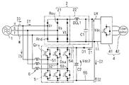
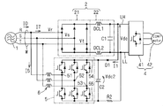
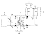
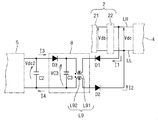
- FIG. 1 is a circuit diagram showing a motor drive system employing the active filter according to the first embodiment.
- the rectifier circuit 2 rectifies the three-phase AC voltages Vr, Vs, and Vt, and outputs the DC voltage Vdc to the pair of DC buses LH and LL.
- a load 4 is connected between the pair of DC buses LH and LL.
- the voltages Vr, Vs, and Vt are supplied from the AC power source 1 through a set of AC input lines W.
- the active filter is a so-called parallel active filter that is connected in parallel to the rectifier circuit 2 between the pair of AC input lines W and the pair of DC buses LH and LL.
- the active filter includes an inverter 5, a capacitor C2, and a pair of current limiting elements.
- One of the pair of current limiting elements is a diode, and in the first embodiment, the pair of current limiting elements is a pair of diodes.
- the pair of diodes are diodes D1 and D2, respectively. Both of these connect the pair of ends of the capacitor C2 to the pair of DC buses LH and LL, respectively. Both diodes D1 and D2 are arranged in a direction that is forward with respect to DC voltage Vdc.
- the potential of the DC bus LH is higher than the potential of the DC bus LL.
- the anode of the diode D1 is connected to the DC bus LH, and the cathode of the diode D2 is connected to the DC bus LL.
- the cathode of the diode D1 is connected to the high potential end of the capacitor C2, and the anode of the diode D2 is connected to the low potential end of the capacitor C2.
- the inverter 5 includes a set of AC side terminals 51, 52, 53 connected to a set of AC input lines W via the interconnection reactor 6, and a pair of DC side terminals 54, 55 connected to both ends of the capacitor C2. And have. Further, the inverter 5 includes a plurality of switching elements that connect each of the AC side terminals 51, 52, 53 and each of the DC side terminals 54, 55. In FIG. 1, these switching elements are shown as IGBTs (insulated gate bipolar transistors). The inverter 5 further includes a plurality of diodes connected in antiparallel to each of these switching elements.
- the rectifier circuit 2 includes a diode bridge 21 and a low-pass filter 22.
- the low-pass filter 22 is provided between the diode bridge 21 and the pair of DC buses LH and LL.
- the diode bridge 21 is provided between the pair of AC input lines W and the low-pass filter 22.
- the low-pass filter 22 is desirably provided from the viewpoint of suppressing harmonic components due to switching of the inverter 5. However, it is not essential in the function that the active filter compensates the harmonic current caused by the load 4.
- the low-pass filter 22 includes a reactor DCL1 provided between the DC bus LH and the diode bridge 21, and a capacitor C1 provided between the pair of DC buses LH and LL.
- Reactor DCL1 may be provided between DC bus LL and diode bridge 21.
- the load 4 is a DC load, but a harmonic current flows.
- the load 4 includes an inverter 41 and a motor 42.
- the inverter 41 converts the DC voltage Vdc into an AC voltage and supplies it to the motor 42.
- the motor 42 is, for example, an AC motor that drives a compressor that compresses the refrigerant.
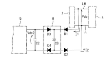
- FIG. 2 is a circuit diagram showing a motor drive system employing an active filter as a comparative example with respect to the first embodiment.
- the active filter shown in FIG. 2 corresponds to a structure in which the diode D2 of the active filter shown in FIG.
- the low potential side ends of the capacitors C1 and C2 are commonly connected to the DC bus LL.
- the S-phase voltage Vs is higher than the R-phase voltage Vr.
- the component of current I5 that flows from the S phase to the R phase is the upper arm side diode Dsu corresponding to the S phase of inverter 5 and the upper arm side that is conducting corresponding to the R phase. It flows through the switching element Qru.
- the component of the current I7 that flows from the S phase to the R phase flows through the upper arm side diode Rsu corresponding to the S phase of the diode bridge 21, the reactor DCL1, and the diode D1. A part thereof flows to the capacitor C2, and the other part passes through the upper arm side switching element Qru.
- the description of these currents is the same for both the configuration according to the first embodiment and the configuration according to the comparative example.
- the current I2 can be negative as described above, the current I2 can flow from the DC bus LL to the upper arm side switching element Qru via the capacitor C2.
- the voltage Vdc2 held by the capacitor C2 becomes substantially equal to the DC voltage Vdc held by the capacitor C2. This is because the current for charging the capacitor C2 is substantially the sum of the currents I1 and I2, and the smaller the value of the current I2 (the larger the absolute value if it is negative), the more difficult the capacitor C2 is charged.
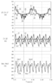
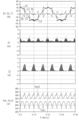
- FIG. 3 is a graph showing the current and voltage of each part in the configuration as a comparative example.
- the waveform of the current I2 shown in the second graph has a long period during which the current I2 is negative.
- the voltage Vdc2 remains slightly above the DC voltage Vdc.
- the current I2 is greatly disturbed by the flow of the current I2, and the compensation of the harmonic current by the current I5 is not sufficient.
- the current I0 has a waveform greatly deviating from the sine wave. Will be presented.
- the waveform of electric current I0, I5, I7 the waveform about one phase, for example, R phase, was shown. The same applies to other figures.
- Measures for increasing the voltage Vdc2 to be greater than the DC voltage Vdc include increasing the capacitance of the capacitor C1 to suppress pulsation of the DC voltage Vdc.
- FIG. 4 is a graph showing the current and voltage of each part in the configuration as a comparative example.
- the capacitance of the capacitor C1 is selected to be larger in the case shown in FIG. 4 (several thousand ⁇ F) than in the case shown in FIG. 3 (several tens ⁇ F).
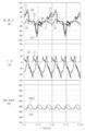
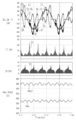
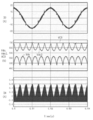
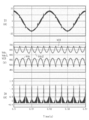
- FIG. 5 is a graph showing the current and voltage of each part in the configuration according to the first embodiment. However, the capacitance of the capacitor C1 was made uniform with the case shown in FIG.
- the current I2 is positive, so that the current charging the capacitor C2 is more in the configuration according to the first embodiment than in the comparative example. Becomes larger. Therefore, the voltage Vdc2 is also significantly higher than the DC voltage Vdc, and the harmonic component of the current I7 by the current I5 can be sufficiently compensated. As a result, the waveform of the current I0 is almost sinusoidal.
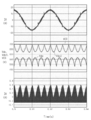
- FIG. 6 is a graph showing the current and voltage of each part in the configuration according to the first embodiment. However, the capacitance of the capacitor C1 is made equal to that shown in FIG.
- the voltage Vdc2 is further increased by suppressing the pulsation of the DC voltage Vdc (both in FIG. 5 and FIG. (The peak value of the voltage Vdc is about 280V. In FIG. 5, the voltage Vdc2 is about 320V, whereas in FIG. 6, the voltage Vdc2 is about 340V).
- the current I7 is more likely to be disturbed when the capacitance of the capacitor C1 is larger (FIG. 6), but the current I5 is well compensated for this disturbance, and the waveform of the current I0 is almost sinusoidal.
- the effect of the first embodiment is exhibited regardless of the capacitance of the capacitor C1. That is, for example, an electrolytic capacitor large enough to smooth the pulsation of the DC voltage Vdc can be connected to the capacitor C1 in parallel.
- the capacitor C2 that is normally included in the active filter is connected to the pair of DC buses LH and LL via the pair of diodes D1 and D2, and thus the direct current voltage is reduced.
- a voltage Vdc2 higher than Vdc can be obtained to suppress harmonic current. This is advantageous in that it does not require a step-up chopper as shown in Patent Document 1 or a transformer as shown in Patent Document 2.
- FIG. 7 is a circuit diagram showing a motor drive system employing the active filter according to the second embodiment.
- the active filter according to the second embodiment is obtained by replacing the diode D2 with the resistor R2 with respect to the active filter according to the first embodiment (see FIG. 1).
- the active filter according to the second embodiment is common to the active filter according to the first embodiment in that the active filter according to the second embodiment includes the pair of current limiting elements described above, but one of the pair of current limiting elements. Is a diode D1, and the other is a resistor R2.
- Resistor R2 limits current I2 and reduces the absolute value of current I2. In other words, the current I2 causes a voltage drop in the resistor R2. Therefore, the voltage Vdc2 can be kept larger than the DC voltage Vdc.
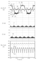
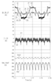
- FIG. 8 is a graph showing the current and voltage of each part in the configuration according to the second embodiment. However, the capacitance of the capacitor C1 was made uniform with the case shown in FIG.
- the current I2 in the second embodiment is different from the current I2 in the first embodiment, and has a negative period similar to the current I2 in the comparative example.
- the maximum absolute value of the current I2 in the second embodiment is less than or equal to half the maximum absolute value of the current I2 in the comparative example.
- the voltage Vdc2 of about 310 V is obtained also in the second embodiment.
- FIG. 9 is a graph showing the current and voltage of each part in the configuration according to the second embodiment. However, the capacitance of the capacitor C1 is made equal to that shown in FIG.
- the voltage Vdc2 is further increased by suppressing the pulsation of the DC voltage Vdc (both in FIG. 5 and FIG. 6, the DC voltage Vdc2 is increased).
- the peak value of the voltage Vdc is about 280V, but in FIG. 5, the voltage Vdc2 is about 310V, whereas in FIG. 6, the voltage Vdc2 is about 310 to 320V).
- the current I7 is more likely to be disturbed when the capacitance of the capacitor C1 is larger (FIG. 9), but the current I5 is well compensated for this disturbance, and the waveform of the current I0 is almost sinusoidal.
- the capacitor C2 that is normally provided in the active filter is simply connected to the pair of DC buses LH and LL via at least one diode D1 and the resistor R2 that is a current limiting element.
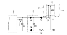
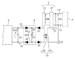
- FIG. 10 is a circuit diagram showing a motor drive system employing the active filter according to the third embodiment.
- the active filter according to the third embodiment is obtained by adding a reactor DCL2 in the low-pass filter 22 to the active filter according to the first embodiment (see FIG. 1).
- the low-pass filter 22 is not essential in the first embodiment, but the low-pass filter 22 is essential in the third embodiment.
- the low-pass filter 22 includes a reactor DCL1 provided between the DC bus LH and the diode bridge 21, a reactor DCL2 provided between the DC bus LL and the diode bridge 21, and a DC bus LH. , LL, the capacitor C1 is provided.
- the reactors DCL1 and DCL2 are connected in series between the pair of terminals on the output side of the diode bridge 21 with the capacitor C1 interposed therebetween.
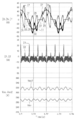
- FIG. 11 is a graph showing the current and voltage of each part in the configuration according to the first embodiment, and shows the same contents as FIG. However, it is a graph which expands and shows the vertical axis
- the waveforms of the currents I1 and I2 are greatly different. This is due to non-equilibrium in the path through which the currents I1 and I2 flow. Due to the non-equilibrium, the waveforms of all of the currents I0, I5, and I7 are shown thick in the section where the current I7 is negative. The fact that this waveform appears thick shows that the carrier signal used for controlling the switching of the inverter 5 is superimposed, even though the low-pass filter 22 is used.
- the first path is a path that passes through the upper arm side diode Dsu corresponding to the S phase of the inverter 5 and the conducting upper arm side switching element Qru corresponding to the R phase in this order.
- the second path is a path that flows as the current I1, and that passes through the upper arm side diode Rsu, the reactor DCL1, the DC bus LH, the diode D1, and the upper arm side switching element Qru corresponding to the S phase of the diode bridge 21 in this order. It is. Even in the configuration according to the first embodiment shown in FIG. 1, the reactor DCL1 exists in the second path.
- the component from the R phase to the S phase in the current I5 has two paths.
- the first path is a path that passes through the lower arm side switching element Qrd in conduction corresponding to the R phase and the lower arm side diode Dsd corresponding to the S phase of the inverter 5 in this order.
- the second path is a path that flows as the current I2 and that passes through the lower arm side switching element Qrd, the diode D2, the DC bus LL, and the lower arm side diode Rsd corresponding to the S phase of the diode bridge 21.
- the reactor DCL2 in the second path Exists.
- the reactors DCL1 and DLC2 exist in the paths through which the currents I1 and I2 flow, respectively. Thereby, the unbalance of the currents I1 and I2 is alleviated.
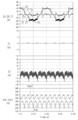
- FIG. 12 is a graph showing the current and voltage of each part in the configuration according to the third embodiment, and shows the contents corresponding to FIG. Compared to the case shown in FIG. 10, in the case shown in FIG. 11, the waveforms of the currents I1 and I2 are similar, and the superposition of the carrier signals in the waveforms of the currents I0, I5 and I7 is reduced. You can see that.
- a pair of reactors DCL 1 and DCL 2 are connected in series on the output side of the diode bridge 21 while sandwiching the capacitor C 1.
- the unbalance of the currents I1 and I2 is alleviated, so that the carrier component used for controlling the inverter 5 is reduced in the current I0.
- FIG. 13 is a circuit diagram showing a motor drive system in which an active filter according to a first modification is employed.
- the diode D1 is replaced with a resistor R1.
- Such a configuration is similar to the configuration shown in the second embodiment (see FIG. 7), and the resistor R1 functions as a current limiting element, and a similar effect can be obtained.
- FIG. 14 is a circuit diagram showing a motor drive system in which an active filter according to a second modification is employed.
- the diode D2 is replaced with a resistor R2.
- the same effects as those in the third embodiment can be obtained.
- the current I1 flows through the diode D1 and the current I2 flows through the resistor R2, the effect of mitigating the unbalance of the currents I1 and I2 is expected in the third embodiment.
- the first embodiment, the second embodiment, the third embodiment, or the modifications can be sent in combination with each other as long as the respective effects are not destroyed.
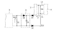
- FIG. 15 is a circuit diagram partially showing a configuration of an active filter according to the fourth embodiment.
- the active filter according to the fourth embodiment is obtained by adding a clamp circuit 8 to the active filter according to the first embodiment (see FIG. 1).
- Such a clamp circuit 8 is particularly suitable for reducing the capacitance of the capacitors C1 and C2.
- a so-called electrolytic capacitorless inverter see, for example, Patent Document 4 and Patent Document 5
- the capacitance of the capacitor C2 can also be reduced.
- the capacitances of the capacitors C1 and C2 are low, the surge current output from the rectifier circuit 2 and the inverter 5 has a great influence on the DC voltage Vdc and the voltage Vdc2 (see the first embodiment). Therefore, by providing the clamp circuit 8, such influence is reduced.
- the clamp circuit 8 includes a clamp diode D3 and a clamp capacitor C3.
- the clamping diode D3 is provided between the capacitor C2 and the diode D1, which is a current limiting element, and has a reverse direction with respect to the DC voltage Vdc. More specifically, the clamping diode D3 has an anode connected to the capacitor C2 and a cathode connected to the cathode of the diode D1.
- a pair of current limiting elements, diodes D1 and D2, are connected in series with a clamping capacitor C3 between DC buses LH and LL.
- the diode D1 is connected to one end of the capacitor C1 through a clamping diode D3. Therefore, specifically, the clamping capacitor C3 is connected between the cathode of the diode D1 and the anode of the diode D2. In other words, the clamping capacitor C3 is connected in parallel with the capacitor C2 via the clamping diode D3 on the capacitor C2 side of the diode D1.
- FIG. 16 is a graph showing the current and voltage of each part in a motor drive system employing an active filter as a comparative example with respect to the fourth embodiment.
- the comparative example has a configuration in which the diode D2 shown in FIG. That is, the relationship of the comparative example with respect to the fourth embodiment is the same as the relationship of the comparative example (in the first embodiment) with respect to the first embodiment.
- FIG. 17 is a graph showing the current and voltage of each part in the motor drive system employing the active filter according to the fourth embodiment.
- the currents I0, I5, and I7 have been described in the first embodiment and are illustrated in FIG.
- the capacitor C2 is connected to the pair of DC buses LH and LL via the pair of diodes D1 and D2.
- the voltage Vdc2 higher than the DC voltage Vdc can be obtained, and the harmonic current can be suppressed.
- FIG. 18 is a graph showing the current and voltage of each part in the motor drive system in which the active filter of the third modified example, which is a modification of the fourth embodiment, is employed.
- the third modification is different from the fourth embodiment in that the low-pass filter 22 has a configuration adopted in the third embodiment, that is, between the pair of terminals on the output side of the diode bridge 21 and the reactors DCL1, DCL2.
- the relationship of the third modified example with respect to the fourth embodiment is the same as the relationship of the third embodiment with respect to the first embodiment.
- the waveforms of the currents I0, I5, and I7 shown in FIG. 17 are shown thick in the section where the current I7 is negative. This waveform looks thick because, as described in the third embodiment, the switching of the inverter 5 is controlled even though the low-pass filter 22 is employed in the first embodiment. It is apparent that the carrier signal employed in is superimposed. This is due to non-equilibrium in the path through which the currents I1 and I2 flow.
- the unbalance of the currents I1 and I2 is alleviated, and the carrier component used for controlling the inverter 5 is reduced at the current I0.
- FIG. 19 is a circuit diagram partially showing a configuration of an active filter according to a fourth modification, which is a modification of the fourth embodiment.
- the fourth modification employs a resistor R2 in place of the diode D2 as a current limiting element with respect to the fourth embodiment. That is, the relationship of the fourth modified example with respect to the fourth embodiment is the same as the relationship of the second embodiment with respect to the first embodiment.
- FIG. 20 is a graph showing the current and voltage of each part in the motor drive system in which the active filter according to the fourth modification is adopted.
- the current I2 has many negative periods, but the voltage Vdc2 is clearly higher than the DC voltage Vdc.
- the same effect as that of the second embodiment can be obtained in the fourth modified example.
- FIG. 21 is a circuit diagram partially showing the configuration of the active filter according to the fifth embodiment.
- the clamp circuit 8 has a configuration in which a clamp diode D4 is added to the clamp circuit 8 shown in the fourth embodiment.
- the clamping diode D4 is connected in series with the clamping diode D3 and the clamping capacitor C3 between a pair of ends of the capacitor C2.
- the clamping diode D4 has a reverse direction with respect to the DC voltage Vdc. More specifically, the clamp diode D4 has an anode connected to the anode of the diode D2 and a cathode connected to the capacitor C2.
- the clamping diode D4 and the diode D2 are connected in series, and their forward directions are opposite to each other. Therefore, the current flowing through the diodes D1 and D2 and the clamping diodes D3 and D4 always charges the clamping capacitor C3. Therefore, the current capacity required for the clamping diode D3 can be reduced by providing the clamping diode D4. Moreover, the current capacity required for the clamping diode D4 is sufficient to be about the same as the current capacity required for the clamping diode D3. Therefore, the current capacity required for the diodes D1 and D2 can also be reduced.
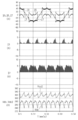
- FIG. 22 is a graph showing the current and voltage of each part in the motor drive system employing the active filter according to the fifth embodiment.
- the currents I1 and I2 in the fifth embodiment are smaller than the currents I1 and I2 (see FIG. 17) in the fourth embodiment. This is based on the reduction of the current capacity required for the diodes D1 and D2 and the clamping diodes D3 and D4.
- the carrier components in the currents I0, I5 and I7 are reduced as compared with the fourth embodiment.
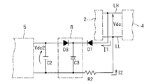
- FIG. 23 is a circuit diagram partially showing a configuration of an active filter according to a fifth modification.
- the fifth modification employs a resistor R2 in place of the diode D2 as a current limiting element, as compared with the fifth embodiment.
- the relationship of the fifth modification example to the fifth embodiment is the same as the relationship of the second embodiment to the first embodiment.
- FIG. 24 is a graph showing the current and voltage of each part in the motor drive system in which the active filter according to the fifth modification is adopted.
- the current I2 has many negative periods, but the voltage Vdc2 is clearly higher than the DC voltage Vdc. In this way, the same effect as in the second embodiment can be obtained in the fifth modification.
- the carrier component cannot be blocked as much as the reverse current of the diode D2. Therefore, the improvement degree of the waveform in the current I0 is about the same as the case where the clamping diode D4 is not provided (fourth modification: see FIG. 20). In other words, when the resistor R2 is employed instead of the diode D2 as the current limiting element, it can be said that the presence or absence of the clamping diode D4 has little effect on the effect.
- FIG. 25 is a graph showing the current and voltage of each part in a motor drive system employing an active filter as a comparative example with respect to the fifth embodiment.
- the comparative example has a configuration in which the diode D2 shown in FIG. That is, the relationship of the comparative example with respect to the fifth embodiment is the same as the relationship of the comparative example (in the first embodiment) with respect to the first embodiment.
- FIG. 26 is a circuit diagram partially showing the configuration of the active filter according to the fifth embodiment.
- I4 and the voltage VC3 applied to the clamping capacitor are further introduced.
- the voltage Vdb is based on the DC bus LL
- the current I8 is a positive direction from the diode D1 and the clamping diode D3 to the diode D2 and the clamping diode D4
- the voltage VC3 is the diode D2 and the clamping diode D4. It was based on the connection point.
- FIG. 27 is a circuit diagram showing an equivalent circuit in a motor drive system in which the active filter according to the fifth embodiment is employed. In this equivalent circuit, however, the common mode voltage is noted.
- the diode bridge 21 generates a common mode voltage Vdbc having a voltage Vdb
- the inverter 5 generates a common mode voltage Vfc having a voltage Vdc2.
- the voltages Vr, Vs, Vt obtained from the AC power supply 1 form a three-phase AC, so the common mode voltage Vdbc can be obtained by the equation (1).
- Vdbc (Vr + Vs + Vt) / 3 (1)
- Vfc (Vu + Vv + Vw) / 3 (2)
- FIG. 28 is a graph illustrating the common mode voltage Vfc.
- the switching operation of the inverter 5 is determined by comparing the carrier CW with the signal waves Vu *, Vv *, Vw *.
- the signal waves Vu *, Vv *, Vw * correspond to the command values of the voltages Vu, Vv, Vw.
- the voltage Vu matches the voltage Vdc2 when the carrier CW takes a value equal to or higher than the signal wave Vu *, and otherwise the voltage Vu becomes zero.
- the common mode voltage Vfc is a step-like waveform that takes four values of 0, 1/3, 2/3, and 1 times the voltage Vdc2. Presents.
- the fundamental frequency of the waveform matches the frequency of the carrier CW.
- the signal waves Vu *, Vv *, and Vw * are expressed by Expression (3).
- the phase ⁇ for the period of the modulation factor K and the signal waves Vu *, Vv *, Vw * was introduced.
- Vu K ⁇ sin ( ⁇ )
- Vv K ⁇ sin ( ⁇ -2 ⁇ / 3)
- Vw K ⁇ sin ( ⁇ + 2 ⁇ / 3)
- the half-value a of the time when the voltage Vu takes the voltage Vdc2 the half-value b of the time when the voltage Vv takes the voltage Vdc2
- the half-value c of the time when the voltage Vw takes the voltage Vdc2 are expressed by Expression (4)
- the period Tsw of the carrier CW was introduced.
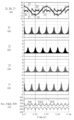
- FIG. 29 is a graph for explaining common mode noise in the fifth embodiment.
- the DC voltage Vdc has a waveform smoothed by the action of the low-pass filter 22.
- the common mode voltage Vdbc exhibits fine fluctuations around 200V.
- the diode bridge 21 either one of the upper arm side diode and the lower arm side diode connected in series conducts, so the common mode voltage Vdbc is about 1/3 of the DC voltage Vdc.
- the voltage Vdc2 exhibits an envelope connecting the upper limit of the common mode voltage Vfc.
- the common mode voltage Vcom is the sum of the common mode voltages Vdbc and Vfc, and corresponds to the common mode voltage of the voltage VC3 as understood from FIG. Therefore, similarly to the behavior of the voltage Vdc2 with respect to the common mode voltage Vfc, the voltage VC3 also presents an envelope that almost connects the upper limit of the common mode voltage Vcom. However, the voltage VC3 is higher by about Vdc / 3 than the voltage Vdc2.
- the voltage VC3 is higher than the voltage Vdc2, and the current I8 is also large. This requires a large power capacity for the clamp capacitor C3, and prevents the clamp circuit 8 and thus the entire active filter from being made small and inexpensive.
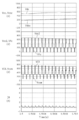
- FIG. 30 various quantities viewed on a more macroscopic time axis are shown in FIG.
- currents I3, I4 and voltage VC3 are shown in addition to the currents I0, I1, I2, I5 and I7 and the DC voltage Vdc and voltage Vdc2 already described in the fifth embodiment.
- the graph in FIG. 30 is slightly different from the graph in FIG. 22 because the DC voltage Vdc is set differently.
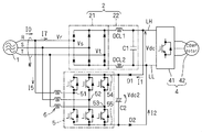
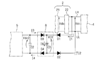
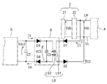
- FIG. 31 is a circuit diagram partially showing the configuration of the active filter according to the sixth embodiment.
- the configuration shown in FIG. 31 is different from the configuration shown in FIG. 26 (according to the fifth embodiment) in that a common mode choke 9 is added.
- the common mode choke L9 has reactors L91 and L92 that are inductively coupled with the same polarity.
- Reactor L91 is connected in series with diode D1 between DC bus LH and one end (high potential end) of capacitor C2.
- Reactor L92 is connected in series with diode D2 between DC bus LL and the other end (low potential end) of capacitor C2. Further, both reactors L91 and L92 are on the side of capacitor C2 with respect to clamping capacitor C3 or on the side opposite to capacitor C2.
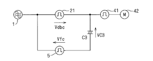
- FIG. 32 is a circuit diagram showing an equivalent circuit in a motor drive system employing the active filter according to the sixth embodiment.
- FIG. 32 shows an equivalent circuit focusing on the common mode voltage, as in FIG.
- the common mode choke L9 is arranged between the inverter 5 and the clamping capacitor C3, and the voltage V9 is generated in the same direction as the voltage VC3.
- the common mode voltage Vcom is canceled.
- the common mode current flowing in the currents I5 and I7 is also canceled, and the current I8 is also reduced.
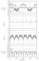
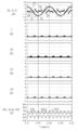
- FIG. 33 is a graph for explaining common mode noise in the sixth embodiment, and shows the same quantities as in FIG. It can be seen that the current I8 becomes small and the voltage VC3 becomes about the voltage Vdc2. Therefore, the power capacity required for the clamping capacitor C3 is reduced.
- FIG. 34 shows various quantities viewed on a more macroscopic time axis, and shows the same quantities as FIG. It can be seen that the voltage VC3 is not only about the voltage Vdc2, but the currents I1, I2, I3, and I4 are also reduced. This is advantageous from the viewpoint of reducing the power capacity required for the diodes D1 and D2 and the clamping diodes D3 and D4.
- the magnetic flux ⁇ cmc flowing in the common mode choke L9 is expressed by Expression (5).
- the symbol ⁇ and the symbol dt indicate the time integration of the amount sandwiched between these two.
- the peak value ⁇ peak is examined.
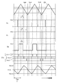
- the case of c ⁇ a ⁇ b ( ⁇ Tsw / 2) will be described as shown in FIG. This corresponds to the case of ⁇ / 6 ⁇ ⁇ / 6.
- the peak value ⁇ peak is obtained by Expression (6).
- the magnetic flux ⁇ cmc is a periodic function having a period of ⁇ / 6 with respect to the phase ⁇ .
- the magnetic flux ⁇ cmc is also shown.
- the peak value ⁇ peak is maximized when the modulation factor K is 0, when all the upper arm side switching elements of the inverter 5 are turned on and all the lower arm side switching elements are turned off, or This is a case where all the arm side switching elements are turned off and all the lower arm side switching elements are turned on.
- the peak value ⁇ peak is expressed by Expression (7).
- the saturation magnetic flux of the core is selected to be larger than the peak value ⁇ peak expressed by the equation (7). That is, the higher the voltage Vdc2 is, the higher the frequency of the carrier CW (this leads to the higher switching frequency of the inverter 5), and the higher the saturation magnetic flux required for the core of the common mode choke L9.
- FIG. 35 is a circuit diagram partially showing a configuration of an active filter according to a sixth modification.
- the sixth modification differs from the sixth embodiment in the position of the common mode choke L9 with respect to the clamp circuit 8.
- the common mode choke L9 in the sixth modification also has reactors L91 and L92 that are inductively coupled with the same polarity.
- Reactor L91 is connected in series with diode D1 between DC bus LH and the high potential end of capacitor C2, and reactor L92 is connected in series with diode D2 between DC bus LL and the low potential end of capacitor C2.
- the reactor L91 is provided between the clamping diode D3 and the diode D1 on the side farther from the capacitor C2 than the clamping capacitor C3.
- the reactor L92 is provided between the clamping diode D4 and the diode D2 on the side farther from the capacitor C2 than the clamping capacitor C3. Therefore, both reactors L91 and L92 are on the side opposite to capacitor C2 with respect to clamping capacitor C3.
- the equivalent circuit of the sixth modification is that the position of the clamp capacitor C3 and the position of the common mode choke L9 are replaced in the equivalent circuit shown in FIG. 32; the clamp capacitor C3 and the common mode The choke L9 is connected in series with each other; even if the two elements connected in series are replaced, the effect of the series connected configuration on the outside of the series connection is not different. .
- FIG. 36, FIG. 37, and FIG. 38 are circuit diagrams partially showing the configurations of active filters according to the seventh modification, the eighth modification, and the ninth modification, respectively.
- the seventh to ninth modifications differ from the sixth embodiment in the position of the common mode choke L9 with respect to the clamp circuit 8.
- the common mode choke L9 in the seventh to ninth modifications also has reactors L91 and L92 that are inductively coupled with the same polarity.
- Reactor L91 is connected in series with diode D1 between DC bus LH and the high potential end of capacitor C2
- reactor L92 is connected in series with diode D2 between DC bus LL and the low potential end of capacitor C2.
- the reactor L91 is provided between the clamping diode D3 and the diode D1 on the side closer to the capacitor C2 than to the clamping capacitor C3.
- the reactor L92 is provided between the clamping diode D4 and the diode D2 on the side closer to the capacitor C2 than the clamping capacitor C3. Therefore, both reactors L91 and L92 are on the capacitor C2 side with respect to clamping capacitor C3.
- the reactor L91 is provided between the DC bus LH and the diode D1.
- Reactor L92 is provided between DC bus LL and diode D2. Therefore, both reactors L91 and L92 are on the side opposite to capacitor C2 with respect to clamping capacitor C3.
- the reactor L91 is provided between the clamping diode D3 and the diode D1 on the side farther from the capacitor C2 than the clamping capacitor C3.
- Reactor L92 is provided between DC bus LL and diode D2. Therefore, both reactors L91 and L92 are on the side opposite to capacitor C2 with respect to clamping capacitor C3.
- the reactor L91 may be provided between the DC bus LH and the diode D1
- the reactor L92 may be provided between the clamping diode D4 and the diode D2 on the side farther from the capacitor C2 than the clamping capacitor C3.
- 39, 40, and 41 are graphs showing currents and voltages of respective parts in a motor drive system in which the active filters according to the seventh modification, the eighth modification, and the ninth modification are employed, respectively. Specifically, currents I0 and I8 and voltages Vdc, Vdc2, and VC3 are shown. Also in these modified examples, the voltage VC3 is suppressed to about the voltage Vdc2 as in the sixth embodiment (see FIG. 34).
- a configuration in which a common mode choke L9 is added to the fifth embodiment is shown.
- the common mode choke L9 may be added to the fourth embodiment.
- the clamping diode D4 may be omitted from the sixth embodiment and the sixth to ninth modifications.
- FIG. 42 is a circuit diagram partially showing the configuration of the tenth modified example obtained by short-circuiting the clamping diode D4 in the sixth modified example.
- FIG. 43 is a graph showing the current and voltage of each part in the motor drive system employing the active filter according to the tenth modification, specifically the currents I0 and I8 and the voltages Vdc, Vdc2 and VC3.
- a three-phase common mode choke may be provided in a three-phase path through which the current I5 flows or a three-phase path through which the current I7 flows.
- the sixth embodiment or the sixth modification is sufficient with a single-phase common mode choke L9 having a small current capacity. This is advantageous from the viewpoint that the entire active filter, and hence the motor drive system that employs the active filter, can be made small and inexpensive.
- a resistor R2 is used instead of the fifth modified example in the same manner as the modified example of the fifth embodiment. It may be adopted.
- a resistor is connected in series with the clamping capacitor C3 so that the current I8 does not fluctuate sharply. May be.
- the configuration including the active filter and the rectifier circuit 2 described above can be grasped as an AC / DC converter.
Abstract
Description
図1は第1の実施の形態にかかるアクティブフィルタが採用されたモータ駆動系を示す回路図である。
図7は第2の実施の形態にかかるアクティブフィルタが採用されたモータ駆動系を示す回路図である。第2の実施の形態にかかるアクティブフィルタは、第1の実施の形態にかかるアクティブフィルタ(図1参照)に対し、ダイオードD2を抵抗R2に置換して得られる。
図10は第3の実施の形態にかかるアクティブフィルタが採用されたモータ駆動系を示す回路図である。第3の実施の形態にかかるアクティブフィルタは、第1の実施の形態にかかるアクティブフィルタ(図1参照)に対し、ローパスフィルタ22においてリアクトルDCL2を追加して得られる。第1の実施の形態ではローパスフィルタ22は必須では無かったが、第3の実施の形態ではローパスフィルタ22は必須となる。
図13は、第1変形例たるアクティブフィルタが採用されたモータ駆動系を示す回路図である。第1の実施の形態で示された構成(図1参照)において、ダイオードD1を抵抗R1に置換した構成を有している。かかる構成は第2の実施の形態で示された構成(図7参照)と同様にして、抵抗R1が電流制限素子として機能し、同様の効果を得ることができる。
図14は、第2変形例たるアクティブフィルタが採用されたモータ駆動系を示す回路図である。第3の実施の形態で示された構成(図10参照)において、ダイオードD2を抵抗R2に置換した構成を有している。かかる構成によれば、第2の実施の形態で説明された内容に鑑みて、第3の実施の形態と同様の効果を得ることができる。但し、電流I1がダイオードD1を流れ、電流I2が抵抗R2を流れるので、電流I1,I2の非平衡が緩和される効果は、第3の実施の形態の方が期待される。
図15は、第4の実施の形態にかかるアクティブフィルタの構成を部分的に示す回路図である。第4の実施の形態にかかるアクティブフィルタは、第1の実施の形態にかかるアクティブフィルタ(図1参照)に対し、クランプ回路8を追加して得られる。
図21は第5の実施の形態にかかるアクティブフィルタの構成を部分的に示す回路図である。第5の実施の形態ではクランプ回路8が、第4の実施の形態で示されたクランプ回路8に対してクランプ用ダイオードD4が追加された構成を有している。
図26は第5の実施の形態にかかるアクティブフィルタの構成を部分的に示す回路図である。但し、第6の実施の形態の説明に用いるため、ダイオードブリッジ21が出力する電圧Vdb、クランプ用コンデンサC3に流れる電流I8、クランプ用ダイオードD3,D4にそれぞれ(順方向電流として)流れる電流I3,I4、及びクランプ用コンデンサに掛る電圧VC3を更に導入している。ここで電圧Vdbは直流母線LLを基準とし、電流I8はダイオードD1及びクランプ用ダイオードD3からダイオードD2及びクランプ用ダイオードD4へと向かう方向を正の方向とし、電圧VC3はダイオードD2とクランプ用ダイオードD4との接続点を基準とした。
Claims (8)
- 一組の交流入力線(W)から入力する交流電圧(Vr,Vs,Vt)を整流し、負荷(4)が両者間に接続される一対の直流母線(LH,LL)へと直流電圧(Vdc)を出力する整流回路(2)に対して、前記一組の交流入力線と前記一対の直流母線との間に並列に接続されるアクティブフィルタであって、
第1コンデンサ(C2)と、
前記第1コンデンサの一対の端のそれぞれを前記一対の直流母線のそれぞれと接続し、少なくともその一方が前記直流電圧に対して順方向となる向きで配置されるダイオード(D1)である、一対の電流制限素子(D1,D2,R2)と、
前記一組の交流入力線に接続された一組の交流側端子(51,52,53)と、前記第1コンデンサの両端に接続された一対の直流側端子(54,55)と、前記交流側端子の各々と前記直流側端子の各々とを接続するスイッチング素子の複数と、前記スイッチング素子の各々に逆並列に接続されたダイオードの複数とを有するインバータ(5)と
を備える、アクティブフィルタ。 - 前記一対の電流制限素子のいずれもが、前記直流電圧に対して順方向となる向きで配置されるダイオード(D1,D2)である、請求項1記載のアクティブフィルタ。
- 前記一対の電流制限素子の他方は抵抗(R2)である、請求項1記載のアクティブフィルタ。
- 前記整流回路(2)は、ダイオードブリッジ(21)と、ローパスフィルタ(22)とを有し、
前記ローパスフィルタ(22)は前記ダイオードブリッジ(21)と前記一対の直流母線(LH,LL)との間に設けられ、
前記ダイオードブリッジ(21)は前記一組の交流入力線(W)と前記ローパスフィルタ(22)との間に設けられ、
前記ローパスフィルタは、一の前記一対の直流母線(LH)と前記ダイオードブリッジ(21)との間に設けられる第1リアクトル(DCL1)と、他の前記一対の直流母線(LL)と前記ダイオードブリッジ(21)との間に設けられる第2リアクトル(DCL2)と、前記一対の直流母線(LH,LL)の間に設けられる第2コンデンサ(C1)とを有する、請求項1乃至請求項3のいずれか一つに記載のアクティブフィルタ。 - 前記第1コンデンサ(C2)と前記一対の電流制限素子(D1,D2,R2)との間に設けられ、前記直流電圧(Vdc)に対して逆方向となるクランプ用ダイオードの少なくとも一つ(D3)と、前記一対の電流制限素子の前記一方よりも前記第1コンデンサ側で前記クランプ用ダイオードを介して前記第1コンデンサと並列に接続されるクランプ用コンデンサ(C3)とを有するクランプ回路(8)
を更に備え、
前記一対の電流制限素子は前記一対の直流母線の間で前記クランプ用コンデンサと直列に接続され、
前記一対の電流制限素子の前記一方(D1)は前記クランプ用ダイオードを介して前記第1コンデンサの一対の端の一方に接続される、請求項1乃至請求項4のいずれか一つに記載のアクティブフィルタ。 - 前記クランプ回路(8)は、前記第1コンデンサ(C2)の前記一対の端の間で前記クランプ用ダイオード(D3)及び前記クランプ用コンデンサ(C3)と直列に接続されて前記直流電圧(Vdc)に対して逆方向となる他のクランプ用ダイオード(D4)を更に有する、請求項5記載のアクティブフィルタ。
- 同極性で誘導結合する第3リアクトル(L91)及び第4リアクトル(L92)を更に備え、
前記第3リアクトルは、
前記第1コンデンサ(C2)の前記一対の端の前記一方と前記直流母線の一方(LH)との間で前記一対の電流制限素子の前記一方(D1)との間で直列に接続され、
前記第4リアクトルは、前記第1コンデンサ(C2)の前記一対の端の他方と前記直流母線の他方(LL)との間で前記一対の電流制限素子の他方(D2,R2)と直列に接続され、
前記第3リアクトルと前記第4リアクトルのいずれもが、前記クランプ用コンデンサ(C3)に対して前記第1コンデンサ(C2)側にあるか、前記第1コンデンサと反対側にある、請求項5又は請求項6記載のアクティブフィルタ。 - 請求項1乃至請求項7のいずれか一つに記載のアクティブフィルタと前記整流回路(2)とを含む、交直変換装置。
Priority Applications (5)
| Application Number | Priority Date | Filing Date | Title |
|---|---|---|---|
| US15/519,315 US10110113B2 (en) | 2014-10-15 | 2015-09-29 | Active filter and AC-DC conversion device |
| EP15850597.4A EP3208926B1 (en) | 2014-10-15 | 2015-09-29 | Active filter and alternating current-direct current conversion device |
| AU2015331531A AU2015331531B2 (en) | 2014-10-15 | 2015-09-29 | Active filter and alternating current-direct current conversion device |
| ES15850597T ES2781116T3 (es) | 2014-10-15 | 2015-09-29 | Filtro activo y dispositivo de conversión de corriente alterna en corriente continua |
| CN201580054940.1A CN107112914B (zh) | 2014-10-15 | 2015-09-29 | 有源滤波器和交流直流转换装置 |
Applications Claiming Priority (4)
| Application Number | Priority Date | Filing Date | Title |
|---|---|---|---|
| JP2014-210821 | 2014-10-15 | ||
| JP2014210821 | 2014-10-15 | ||
| JP2015078968 | 2015-04-08 | ||
| JP2015-078968 | 2015-04-08 |
Publications (1)
| Publication Number | Publication Date |
|---|---|
| WO2016059969A1 true WO2016059969A1 (ja) | 2016-04-21 |
Family
ID=55746517
Family Applications (1)
| Application Number | Title | Priority Date | Filing Date |
|---|---|---|---|
| PCT/JP2015/077556 WO2016059969A1 (ja) | 2014-10-15 | 2015-09-29 | アクティブフィルタ、交直変換装置 |
Country Status (7)
| Country | Link |
|---|---|
| US (1) | US10110113B2 (ja) |
| EP (1) | EP3208926B1 (ja) |
| JP (2) | JP6183434B2 (ja) |
| CN (1) | CN107112914B (ja) |
| AU (1) | AU2015331531B2 (ja) |
| ES (1) | ES2781116T3 (ja) |
| WO (1) | WO2016059969A1 (ja) |
Families Citing this family (9)
| Publication number | Priority date | Publication date | Assignee | Title |
|---|---|---|---|---|
| EP3024133A1 (en) * | 2014-11-24 | 2016-05-25 | Broadband Power Solutions | DC-to-AC power converter |
| JP5920520B1 (ja) * | 2014-12-17 | 2016-05-18 | ダイキン工業株式会社 | 充放電回路、充放電回路の制御方法、充放電回路の制御装置、及び直接形電力変換器 |
| JP6260578B2 (ja) * | 2015-04-17 | 2018-01-17 | トヨタ自動車株式会社 | 送電装置及び受電装置 |
| US11404954B2 (en) * | 2017-09-28 | 2022-08-02 | Carrier Corporation | Pulse width modulation interleaving |
| JP6690662B2 (ja) * | 2018-03-29 | 2020-04-28 | ダイキン工業株式会社 | 電源品質管理システムならびに空気調和装置 |
| CN108879765B (zh) * | 2018-07-02 | 2021-04-02 | 太原理工大学 | 防止微电网交流母线电流畸变的双向功率变换器控制方法 |
| CN111256281B (zh) * | 2018-11-30 | 2021-10-22 | 广东美的制冷设备有限公司 | 运行控制方法及系统、压缩机和空调器 |
| DE102019102550B4 (de) * | 2019-02-01 | 2022-06-30 | Infineon Technologies Austria Ag | Leistungswandler und leistungswandlungsverfahren |
| CN113328639B (zh) * | 2021-07-09 | 2021-11-19 | 四川大学 | 一种大功率的电解制氢整流电源及控制方法 |
Citations (4)
| Publication number | Priority date | Publication date | Assignee | Title |
|---|---|---|---|---|
| JPS60234474A (ja) * | 1984-05-07 | 1985-11-21 | Hitachi Ltd | インバータ装置 |
| JPH08251947A (ja) * | 1995-03-15 | 1996-09-27 | Hitachi Ltd | 電力変換装置の回生制御装置 |
| JP2001145357A (ja) * | 1999-11-11 | 2001-05-25 | Sanken Electric Co Ltd | Ac−dcコンバータ |
| JP2013027990A (ja) * | 2011-07-26 | 2013-02-07 | Sumitomo Heavy Ind Ltd | 射出成形機 |
Family Cites Families (17)
| Publication number | Priority date | Publication date | Assignee | Title |
|---|---|---|---|---|
| US4928052A (en) * | 1987-04-30 | 1990-05-22 | Fanuc Ltd. | Power supply regenerating circuit |
| KR100214686B1 (ko) * | 1997-04-10 | 1999-08-02 | 이종수 | 엘리베이터의 구출운전 겸용 역률 개선장치 |
| JP2002051589A (ja) | 2000-07-31 | 2002-02-15 | Isao Takahashi | モータ駆動用インバータの制御装置 |
| JP2003309977A (ja) * | 2002-04-15 | 2003-10-31 | Toshiba Corp | 電力変換装置 |
| JP4284053B2 (ja) | 2002-11-21 | 2009-06-24 | 株式会社東芝 | 電力変換装置 |
| CN1264269C (zh) | 2002-12-13 | 2006-07-12 | 永大机电工业股份有限公司 | 升降设备的电力控制装置 |
| JP4411845B2 (ja) | 2003-02-13 | 2010-02-10 | 株式会社明電舎 | 並列型ac−dc変換器 |
| TW591870B (en) * | 2003-02-18 | 2004-06-11 | Delta Electronics Inc | Integrated converter with three-phase power factor correction |
| JP2006109558A (ja) * | 2004-10-01 | 2006-04-20 | Matsushita Electric Ind Co Ltd | 空気調和装置 |
| GB2427512A (en) * | 2005-06-23 | 2006-12-27 | Alstom | Electrical power converters |
| EP2095496B1 (de) * | 2006-11-28 | 2012-08-29 | Baumüller Nürnberg GmbH | Aktiv-bremseinheit |
| FI120665B (fi) * | 2007-06-20 | 2010-01-15 | Kone Corp | Kuljetusjärjestelmän tehonohjaus |
| CN201051718Y (zh) * | 2007-06-22 | 2008-04-23 | 北京利德华福电气技术有限公司 | 带有能量回馈装置的功率单元模块 |
| CN101237185A (zh) * | 2007-12-07 | 2008-08-06 | 华中科技大学 | 适用于整流装置的能量回馈与谐波无功补偿系统 |
| US8274803B2 (en) * | 2009-01-09 | 2012-09-25 | Yaskawa America, Inc. | Low stress soft charge circuit for diode front end variable frequency drive |
| CN102044974B (zh) * | 2010-08-11 | 2014-03-19 | 江苏斯达工业科技有限公司 | 一种能量回馈器主电路拓扑结构 |
| JP5850117B2 (ja) | 2013-09-30 | 2016-02-03 | ダイキン工業株式会社 | 電力変換装置 |
-
2015
- 2015-09-29 EP EP15850597.4A patent/EP3208926B1/en active Active
- 2015-09-29 WO PCT/JP2015/077556 patent/WO2016059969A1/ja active Application Filing
- 2015-09-29 AU AU2015331531A patent/AU2015331531B2/en active Active
- 2015-09-29 US US15/519,315 patent/US10110113B2/en active Active
- 2015-09-29 CN CN201580054940.1A patent/CN107112914B/zh active Active
- 2015-09-29 ES ES15850597T patent/ES2781116T3/es active Active
- 2015-09-29 JP JP2015191013A patent/JP6183434B2/ja active Active
-
2017
- 2017-05-22 JP JP2017101035A patent/JP6785719B2/ja active Active
Patent Citations (4)
| Publication number | Priority date | Publication date | Assignee | Title |
|---|---|---|---|---|
| JPS60234474A (ja) * | 1984-05-07 | 1985-11-21 | Hitachi Ltd | インバータ装置 |
| JPH08251947A (ja) * | 1995-03-15 | 1996-09-27 | Hitachi Ltd | 電力変換装置の回生制御装置 |
| JP2001145357A (ja) * | 1999-11-11 | 2001-05-25 | Sanken Electric Co Ltd | Ac−dcコンバータ |
| JP2013027990A (ja) * | 2011-07-26 | 2013-02-07 | Sumitomo Heavy Ind Ltd | 射出成形機 |
Also Published As
| Publication number | Publication date |
|---|---|
| AU2015331531A1 (en) | 2017-05-04 |
| AU2015331531B2 (en) | 2018-04-05 |
| EP3208926B1 (en) | 2020-01-01 |
| US20170237334A1 (en) | 2017-08-17 |
| CN107112914B (zh) | 2019-07-02 |
| JP2016185058A (ja) | 2016-10-20 |
| JP6183434B2 (ja) | 2017-08-23 |
| EP3208926A1 (en) | 2017-08-23 |
| ES2781116T3 (es) | 2020-08-28 |
| US10110113B2 (en) | 2018-10-23 |
| CN107112914A (zh) | 2017-08-29 |
| EP3208926A4 (en) | 2018-05-16 |
| JP2017139965A (ja) | 2017-08-10 |
| JP6785719B2 (ja) | 2020-11-18 |
Similar Documents
| Publication | Publication Date | Title |
|---|---|---|
| JP6785719B2 (ja) | アクティブフィルタ、交直変換装置 | |
| JP5772915B2 (ja) | 直接形電力変換装置および直接形電力変換装置の制御方法 | |
| US9374016B2 (en) | AC-DC converter | |
| KR101189428B1 (ko) | 전력 변환 장치 | |
| US9948200B2 (en) | Charge and discharge circuit, control method for charge and discharge circuit, control device for charge and discharge circuit, and direct power converter | |
| JP5146011B2 (ja) | 直接形交流電力変換装置 | |
| JP5930108B2 (ja) | 電力変換装置 | |
| US20110170322A1 (en) | Power conversion device | |
| US9742272B2 (en) | AC-DC converter | |
| WO2014030181A1 (ja) | 電力変換装置 | |
| JP2015050934A (ja) | 力率補償回路 | |
| JP2002272113A (ja) | 直流リアクトル装置及び高周波抑制制御装置 | |
| JP2009095202A (ja) | インバータ | |
| WO2018179234A1 (ja) | H型ブリッジ変換器およびパワーコンディショナ | |
| JP6480290B2 (ja) | 電力変換装置 | |
| JP2008043096A (ja) | 電力変換装置 | |
| JP6098629B2 (ja) | 電力変換装置 | |
| JP2016092929A (ja) | インバータ回路 | |
| WO2014196370A1 (ja) | 車両用電力変換装置 | |
| JP6772577B2 (ja) | 充放電回路、充放電回路の制御方法、及び直接形電力変換器 | |
| JP2016116387A (ja) | 電源回路 | |
| Marouchos et al. | Investigation on line current compensation techniques for rectifier circuits | |
| JP2013258869A (ja) | 単相/三相変換装置及びその制御方法 |
Legal Events
| Date | Code | Title | Description |
|---|---|---|---|
| 121 | Ep: the epo has been informed by wipo that ep was designated in this application |
Ref document number: 15850597 Country of ref document: EP Kind code of ref document: A1 |
|
| REEP | Request for entry into the european phase |
Ref document number: 2015850597 Country of ref document: EP |
|
| WWE | Wipo information: entry into national phase |
Ref document number: 2015850597 Country of ref document: EP |
|
| WWE | Wipo information: entry into national phase |
Ref document number: 15519315 Country of ref document: US |
|
| NENP | Non-entry into the national phase |
Ref country code: DE |
|
| ENP | Entry into the national phase |
Ref document number: 2015331531 Country of ref document: AU Date of ref document: 20150929 Kind code of ref document: A |