WO2016013448A1 - パンツ型使い捨ておむつ - Google Patents
パンツ型使い捨ておむつ Download PDFInfo
- Publication number
- WO2016013448A1 WO2016013448A1 PCT/JP2015/070124 JP2015070124W WO2016013448A1 WO 2016013448 A1 WO2016013448 A1 WO 2016013448A1 JP 2015070124 W JP2015070124 W JP 2015070124W WO 2016013448 A1 WO2016013448 A1 WO 2016013448A1
- Authority
- WO
- WIPO (PCT)
- Prior art keywords
- sheet
- absorbent
- pants
- type disposable
- convex
- Prior art date
- Legal status (The legal status is an assumption and is not a legal conclusion. Google has not performed a legal analysis and makes no representation as to the accuracy of the status listed.)
- Ceased
Links
Images













Classifications
-
- A—HUMAN NECESSITIES
- A61—MEDICAL OR VETERINARY SCIENCE; HYGIENE
- A61F—FILTERS IMPLANTABLE INTO BLOOD VESSELS; PROSTHESES; DEVICES PROVIDING PATENCY TO, OR PREVENTING COLLAPSING OF, TUBULAR STRUCTURES OF THE BODY, e.g. STENTS; ORTHOPAEDIC, NURSING OR CONTRACEPTIVE DEVICES; FOMENTATION; TREATMENT OR PROTECTION OF EYES OR EARS; BANDAGES, DRESSINGS OR ABSORBENT PADS; FIRST-AID KITS
- A61F13/00—Bandages or dressings; Absorbent pads
- A61F13/15—Absorbent pads, e.g. sanitary towels, swabs or tampons for external or internal application to the body; Supporting or fastening means therefor; Tampon applicators
- A61F13/45—Absorbent pads, e.g. sanitary towels, swabs or tampons for external or internal application to the body; Supporting or fastening means therefor; Tampon applicators characterised by the shape
- A61F13/49—Absorbent pads, e.g. sanitary towels, swabs or tampons for external or internal application to the body; Supporting or fastening means therefor; Tampon applicators characterised by the shape specially adapted to be worn around the waist, e.g. diapers, nappies
- A61F13/496—Absorbent pads, e.g. sanitary towels, swabs or tampons for external or internal application to the body; Supporting or fastening means therefor; Tampon applicators characterised by the shape specially adapted to be worn around the waist, e.g. diapers, nappies in the form of pants or briefs
-
- A—HUMAN NECESSITIES
- A61—MEDICAL OR VETERINARY SCIENCE; HYGIENE
- A61F—FILTERS IMPLANTABLE INTO BLOOD VESSELS; PROSTHESES; DEVICES PROVIDING PATENCY TO, OR PREVENTING COLLAPSING OF, TUBULAR STRUCTURES OF THE BODY, e.g. STENTS; ORTHOPAEDIC, NURSING OR CONTRACEPTIVE DEVICES; FOMENTATION; TREATMENT OR PROTECTION OF EYES OR EARS; BANDAGES, DRESSINGS OR ABSORBENT PADS; FIRST-AID KITS
- A61F13/00—Bandages or dressings; Absorbent pads
- A61F13/15—Absorbent pads, e.g. sanitary towels, swabs or tampons for external or internal application to the body; Supporting or fastening means therefor; Tampon applicators
-
- A—HUMAN NECESSITIES
- A61—MEDICAL OR VETERINARY SCIENCE; HYGIENE
- A61F—FILTERS IMPLANTABLE INTO BLOOD VESSELS; PROSTHESES; DEVICES PROVIDING PATENCY TO, OR PREVENTING COLLAPSING OF, TUBULAR STRUCTURES OF THE BODY, e.g. STENTS; ORTHOPAEDIC, NURSING OR CONTRACEPTIVE DEVICES; FOMENTATION; TREATMENT OR PROTECTION OF EYES OR EARS; BANDAGES, DRESSINGS OR ABSORBENT PADS; FIRST-AID KITS
- A61F13/00—Bandages or dressings; Absorbent pads
- A61F13/15—Absorbent pads, e.g. sanitary towels, swabs or tampons for external or internal application to the body; Supporting or fastening means therefor; Tampon applicators
- A61F13/45—Absorbent pads, e.g. sanitary towels, swabs or tampons for external or internal application to the body; Supporting or fastening means therefor; Tampon applicators characterised by the shape
- A61F13/49—Absorbent pads, e.g. sanitary towels, swabs or tampons for external or internal application to the body; Supporting or fastening means therefor; Tampon applicators characterised by the shape specially adapted to be worn around the waist, e.g. diapers, nappies
- A61F13/494—Absorbent pads, e.g. sanitary towels, swabs or tampons for external or internal application to the body; Supporting or fastening means therefor; Tampon applicators characterised by the shape specially adapted to be worn around the waist, e.g. diapers, nappies characterised by edge leakage prevention means
-
- A—HUMAN NECESSITIES
- A61—MEDICAL OR VETERINARY SCIENCE; HYGIENE
- A61F—FILTERS IMPLANTABLE INTO BLOOD VESSELS; PROSTHESES; DEVICES PROVIDING PATENCY TO, OR PREVENTING COLLAPSING OF, TUBULAR STRUCTURES OF THE BODY, e.g. STENTS; ORTHOPAEDIC, NURSING OR CONTRACEPTIVE DEVICES; FOMENTATION; TREATMENT OR PROTECTION OF EYES OR EARS; BANDAGES, DRESSINGS OR ABSORBENT PADS; FIRST-AID KITS
- A61F13/00—Bandages or dressings; Absorbent pads
- A61F13/15—Absorbent pads, e.g. sanitary towels, swabs or tampons for external or internal application to the body; Supporting or fastening means therefor; Tampon applicators
- A61F13/53—Absorbent pads, e.g. sanitary towels, swabs or tampons for external or internal application to the body; Supporting or fastening means therefor; Tampon applicators characterised by the absorbing medium
- A61F13/531—Absorbent pads, e.g. sanitary towels, swabs or tampons for external or internal application to the body; Supporting or fastening means therefor; Tampon applicators characterised by the absorbing medium having a homogeneous composition through the thickness of the pad
- A61F13/532—Absorbent pads, e.g. sanitary towels, swabs or tampons for external or internal application to the body; Supporting or fastening means therefor; Tampon applicators characterised by the absorbing medium having a homogeneous composition through the thickness of the pad inhomogeneous in the plane of the pad
Definitions
- the present invention relates to a pants-type disposable diaper.
- an absorbent main body including a liquid-permeable surface sheet and a liquid-retaining absorbent, and the absorbent main body is fixed on the non-skin contact surface side of the absorbent main body
- a pant comprising an exterior body, wherein both sides of the exterior body in the front body and both sides of the exterior body in the back body are joined to form a pair of side seal parts, a waist opening, and a pair of leg openings
- Type disposable diapers are known.
- a leak-proof cuff that is raised by an elastic member is provided on both sides in the longitudinal direction of the absorbent main body at the crotch, and the non-skin contact of the side part of the absorbent body It is also known to form a gap capable of storing urine and the like between a sheet covering the contact surface side and a leak-proof cuff (see Patent Document 1).
- a sheet having a concavo-convex shape as a surface sheet of a disposable diaper or a sanitary napkin in order to suppress wetback and improve the wearing feeling (see Patent Documents 2 and 3).
- the surface sheet of the unfolded disposable diaper is a concavo-convex sheet having a configuration in which a sheet shaped into a concavo-convex shape and a lower layer sheet not shaped into a concavo-convex shape are joined to each other in a recess of the upper layer sheet It is described to be used as.
- the leak-proof cuff is joined to the skin contact surface side of the absorbent main body so as to be able to stand up at the crotch, while the abdomen and back. It is common to join to the skin contact surface side of an absorptive main body in the longitudinal direction both ends located in a side part.
- an absorbent main body including a liquid-permeable surface sheet and a liquid-retaining absorbent, and the absorbent main body is fixed on the non-skin contact surface side of the absorbent main body.
- a pair of side surfaces having a ventral side portion, a dorsal side portion, and a crotch portion, wherein both sides of the exterior body on the abdominal side portion and both side portions of the exterior body on the back side portion are joined together.
- the present invention (first invention) comprises an absorbent main body comprising a liquid-permeable topsheet and a liquid-retaining absorbent body, comprising an abdominal part, a back part and a crotch part, a waist opening part and a pair of
- the present invention relates to a pants-type disposable diaper in which a leg opening is formed.
- the top sheet is arranged so as to cover the skin contact surface side of the absorbent body, both side edges in the longitudinal direction of the absorbent body, and the non-skin contact surface side of both longitudinal sides of the absorbent body.
- a pair of leak-proof cuffs are provided on both sides in the longitudinal direction of the absorbent main body, and the leak-proof cuffs are respectively provided on the ventral side portion and the back side portion from the non-skin contact surface side of the absorbent main body. It arrange
- the said absorptive main body has the fixing
- the surface sheet has a concavo-convex region in which convex portions are formed in a dotted shape in a portion covering the skin contact surface side of the absorber, and the non-skin contact surface side on both sides in the longitudinal direction of the absorber
- the part which covers is a non-relief region having no unevenness.
- This invention fixes an absorptive main body located in the non-skin-contacting surface side of this absorptive main body provided with a liquid-permeable surface sheet and a liquid holding
- the present invention relates to a pants-type disposable diaper having an abdominal part, a dorsal part and a crotch part, and having a waist opening and a pair of leg openings.
- a pair of leak-proof cuffs are provided on both sides in the longitudinal direction of the absorbent main body, and the leak-proof cuffs are respectively joined to the skin contact surface side of the absorbent main body at the abdomen and back sides.
- the crotch part in the worn state is erected.
- the top sheet has a concavo-convex region in which convex portions are formed in the shape of dots in the central portion in the width direction of the absorbent main body, and is flat without concavo-convex at both ends in the width direction of the absorbent main body. It has a non-recessed area.
- the leak-proof cuff has an inner joint part and an outer joint part joined to the skin contact surface side of the absorbent main body on one or both of the ventral side part and the back side part, and the inner joint part Is fixed on the uneven region at a portion near the center in the width direction of the absorbent main body, and the outer joint portion is fixed on the non-concave region at a portion near the end in the width direction of the absorbent main body. ing.
- the inner joint portion and the outer joint portion are arranged in the width direction of the absorbent main body across a non-joined region that is not joined on the topsheet, and the exterior body includes a ventral side portion and a back side.
- the waistline gather which has elasticity in the diaper width direction is provided in the part, and the waistline gather in either one or both of the abdominal side part and the back side part has an inner stretchable part overlapping the absorber.
- the outer joint portion and the non-join region in the leak-proof cuff overlap the inner stretchable portion in the diaper thickness direction.
- the pants-type disposable diaper of the first invention comprises all or part of the constituent requirements of the pants-type disposable diaper of the second invention, or all or part of the constituent requirements of the pants-type disposable diaper of the embodiment described later. Preferably it is.
- the present invention (third invention) includes an absorbent main body having a liquid-permeable surface sheet and a liquid-retaining absorbent, and fixing the absorbent main body on the non-skin contact surface side of the absorbent main body
- the present invention relates to a pants-type disposable diaper having an abdominal part, a dorsal part and a crotch part, and having a waist opening and a pair of leg openings.
- the said absorber has a thin part in the edge part of the longitudinal direction located in a stomach side part or a back side part.
- a plurality of waist elastic members are spaced apart in the diaper longitudinal direction in the crotch region from the longitudinal edge of the absorbent body in the abdominal side portion and the back side portion, respectively in the diaper width direction.
- the pant-type disposable diaper of the first invention comprises all or part of the constituent requirements of the pant-type disposable diaper of the third invention, or all or part of the constituent requirements of the pant-type disposable diaper of the embodiment described later. Preferably it is.
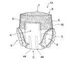
- FIG. 1 is a perspective view of a pants-type disposable diaper that is an embodiment of the present invention (first invention).
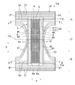
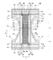
- FIG. 2 is a developed plan view showing a state in which the developed and extended state of the diaper shown in FIG. 1 is viewed from the skin contact surface side.
- the expanded and extended state is a state in which the side seal portion separates and expands, and the elastic member of each portion is extended and expanded in a planar shape.
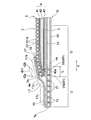
- FIG. 3 is a cross-sectional view schematically showing a cross section taken along the center line CL in the width direction of the diaper shown in FIG. 1 in a worn state.
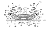
- 4 is a cross-sectional view schematically showing a cross section taken along line II of FIG. FIG.
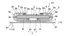
- FIG. 5 is a sectional view schematically showing a section taken along line II-II in FIG.
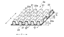
- FIG. 6 is a perspective view showing an uneven area of the top sheet of the diaper shown in FIG.
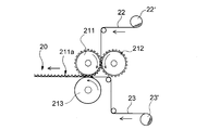
- FIG. 7 is an explanatory diagram of a method for manufacturing the top sheet of the diaper shown in FIG.
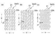
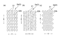
- FIG. 8A to FIG. 8C are schematic enlarged plan views showing other examples of the concavo-convex region in which the convex portions are formed in the form of dots on the surface sheet.
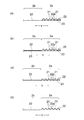
- 9 (a) to 9 (d) are explanatory views of a surface sheet that can be used in the present invention (first invention).
- FIG. 9 (a) is a surface sheet used in the diaper shown in FIG. FIGS.
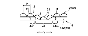
- FIG. 10 is a principal part expanded sectional view in the width direction of the crotch part which shows the principal part of the underpants type disposable diaper which is other embodiment of this invention (1st invention).
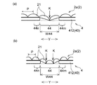
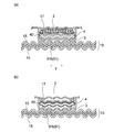
- 11 (a) and 11 (b) are explanatory views (main part enlarged sectional views along the width direction of the crotch part) for explaining a more preferable configuration of the pants-type disposable diaper shown in FIG.
- FIG. 12 is a perspective view of a pants-type disposable diaper that is an embodiment of the present invention (second invention).
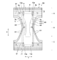
- FIG. 13 is a developed plan view showing a state where the developed and expanded state of the diaper shown in FIG. 12 is viewed from the skin contact surface side.
- the expanded and extended state is a state in which the side seal portion separates and expands, and the elastic member of each portion is extended and expanded in a planar shape.
- FIG. 14 is a cross-sectional view schematically showing a cross section taken along the center line CL in the width direction of the diaper shown in FIG. 12 in a worn state.
- FIG. 15 is a cross-sectional view schematically showing a cross section taken along line II of FIG.
- FIG. 16 is a cross-sectional view schematically showing a cross section taken along line II-II in FIG.
- FIG. 17 is a perspective view showing an uneven region of the top sheet of the diaper shown in FIG. 18 is a diagram illustrating an arrangement example of the inner joint portion and the outer joint portion arranged in the width direction of the absorbent main body
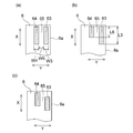
- FIG. 18 (a) is an arrangement in the diaper illustrated in FIG. 12, and
- FIG. 18 (b) and FIG. 18 (c) is a diagram showing an example of another arrangement that can be adopted.
- FIG. 19 is a developed plan view showing a state where the developed and extended state of the diaper shown in FIG. 12 is viewed from the non-skin contact surface side.
- FIG. 20 (a) to 20 (c) are schematic enlarged plan views showing other examples of the concavo-convex region in which the convex portions are formed in the shape of dots on the surface sheet.
- 21 (a) to 21 (d) are explanatory views of a surface sheet that can be used in the present invention (second invention).
- FIG. 21 (a) is a surface sheet used for the diaper shown in FIG. 21 (b) to 21 (d) are cross-sectional views showing other examples of the surface sheet that can be used as the surface sheet.
- FIG. 22 is a perspective view of a pants-type disposable diaper that is an embodiment of the present invention (third invention).
- FIG. 23 is a developed plan view showing a developed and extended state of the diaper shown in FIG. 22 as viewed from the skin contact surface side.
- the expanded and extended state is a state in which the side seal portion separates and expands, and the elastic member of each portion is extended and expanded in a planar shape.
- 24 is a cross-sectional view schematically showing a cross section taken along line III-III in FIG. 25 is a cross-sectional view schematically showing a cross section taken along line IV-IV in FIG.
- FIG. 26A is a view corresponding to FIG. 25 showing the contracted state
- FIG. 26B is a view corresponding to FIG.
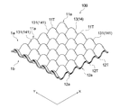
- FIG. 27 is a perspective view of a three-dimensional sheet used as the top sheet of the diaper shown in FIG.
- FIG. 28 is an explanatory diagram of a method for manufacturing the three-dimensional sheet shown in FIG.
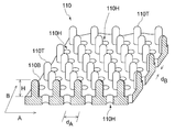
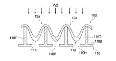
- FIG. 29 is a schematic perspective view of an uneven nonwoven fabric that can be preferably employed as a surface sheet in the present invention (third invention).
- FIG. 30 is a schematic diagram illustrating a cross section along the thickness direction of the uneven nonwoven fabric illustrated in FIG. 29.
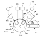
- FIG. 31 is a schematic diagram showing an apparatus suitably used for manufacturing the uneven nonwoven fabric shown in FIG.
- FIG. 32 is an enlarged view showing a main part of the support in the manufacturing apparatus shown in FIG. FIG.
- FIG. 33 is a schematic diagram showing a state in which the web is shaped by the manufacturing apparatus shown in FIG.
- FIG. 34 is a schematic view showing a state in which the fibers of the web are heat-sealed by the apparatus shown in FIG.
- FIG. 35 is a plan view showing still another example of the uneven nonwoven fabric that can be preferably employed as the surface sheet in the present invention (third invention).
- FIG. 36 is an explanatory diagram of a method for measuring bulk softness.
- the pants-type disposable diaper of Patent Document 1 has a structure that hardly absorbs liquid from the non-skin contact surface side of the side of the absorbent body, and there is room for improvement in terms of improvement in wearing feeling and absorption performance. .
- the present inventors use a sheet having an uneven shape as the top sheet, and when the leak-proof cuff is joined onto the top sheet, the joined leak-proof cuff is compressed and filled into a packaging bag at the time of manufacture. It has been found that it is easy to peel off during wearing or during wearing.
- the absorbent body when the absorbent main body is joined to the exterior body in which the waistline gathers are formed, the absorbent body may be excessively shrunk in the diaper width direction at the portion overlapping the waistline gathers, which may cause inconveniences such as a sense of incongruity and lack of an absorbent surface. . Therefore, the elastic member for forming the waistline gathers is also cut at a portion overlapping the absorber. However, when all the elastic members for forming the waistline gathers are cut at the portion overlapping the absorber, the fit property in the vicinity of the end of the absorber of the pants-type disposable diaper is likely to be lowered, and the leakage prevention property is lowered.
- Patent Document 6 describes that a part of the plurality of waistline elastic members is arranged so as to overlap the end of the absorber.
- Patent Document 6 what has a special absorptive core is used as an absorber, and when using a normal absorber, wrinkles and twist arise in the edge part of an absorber, and a wearer There is a concern that makes you feel uncomfortable.
- it has been difficult to achieve both the fit in the vicinity of the end of the absorbent body and the sense of incongruity.
- the present invention relates to a pants-type disposable diaper that can solve the problems of the prior art.
- a pants-type disposable diaper 1A (hereinafter also referred to as “diaper 1A”) which is an embodiment of the first invention of the present invention and a pants-type disposable diaper 1B (hereinafter also referred to as “diaper 1B”) which is an embodiment of the second invention of the present invention.
- the absorbent main body 5 is positioned on the non-skin contact surface side of the absorbent main body 5 to fix the absorbent main body 5.
- the exterior body 10 is provided.
- the diaper 1A, 1B has the longitudinal direction X equivalent to a wearer's front-back direction and the width direction Y orthogonal to this, as shown in FIG. 2 or FIG.
- side edge part A1, A1 of the exterior body 10 in the ventral part A and side edge part B1, B1 of the exterior body 10 in the back side part B are mutually connected by well-known joining means, such as a heat seal and an ultrasonic seal.
- a pair of side seal portions S, S, a waist opening 7 and a pair of leg openings 8, 8 are formed by joining.
- the exterior body 10 of the diapers 1A and 1B forms the outer surface of the diapers 1A and 1B.
- the ventral part A, the dorsal part B, and the crotch part C are divided into three regions so that the diapers 1A, 1B in the expanded and extended state (see FIG. 2 or FIG. 13) are equally divided into three in the longitudinal direction X. It is each area when doing.
- the side seal part is peeled off, the diaper is set in the expanded state, the expanded state diaper is extended by the elastic member of each part, and the design dimensions (the state in which the influence of the elastic member is completely eliminated) It is the same as when it is spread in a flat shape.
- the center line CL in the width direction of the diapers 1A and 1B is a virtual straight line extending in the width direction Y by dividing the entire length of the diapers 1A and 1B in the longitudinal direction.
- the skin contact surface is a surface directed to the wearer's skin side when worn in a pants-type disposable diaper or a constituent member thereof (for example, an absorbent main body), and the non-skin contact surface is In the pants-type disposable diaper or its constituent members, it is a surface directed to the side opposite to the wearer's skin side (clothing side) when worn.
- the absorbent main body 5 has a vertically long shape in the longitudinal direction X of the diapers 1A and 1B, as shown in FIG. 3 to FIG. 5 or FIG.
- a liquid-permeable top sheet 2 and a liquid-retaining absorbent 4 are provided.
- the absorbent main body 5 is joined to the central portion of the outer package 10 by a known joining means (adhesive or the like) such that the longitudinal direction thereof coincides with the longitudinal direction X of the diapers 1A and 1B in the expanded and extended state.
- the absorbent body 4 has a shape that is long in the longitudinal direction X of the diapers 1 ⁇ / b> A and 1 ⁇ / b> B, similarly to the absorbent main body 5.
- the absorbent body 4 in the diapers 1 ⁇ / b> A and 1 ⁇ / b> B includes an absorbent core 40, a skin contact surface side and a non-skin contact surface of the absorbent core 40.
- the absorbent core 40 includes a rectangular lower absorbent core 412 and an upper absorbent core 411 laminated on a part of the lower absorbent core 412.
- the absorptive core 40 has a central region 42 that is relatively thick due to the upper absorbent core 411 being laminated on the lower absorbent core 412 at the center in the width direction of the crotch C,
- the upper absorbent core 411 is not laminated on the lower absorbent core 412 on both sides of the central region 42 and has a pair of side regions 43 and 43 that are thinner than the central region 42.
- diaper 1A it has the level
- the upper absorbent core 411 and the lower absorbent core 412 are both made of a fiber assembly or a structure in which a water absorbent polymer is held.
- the core wrap sheet 41 is made of tissue paper or a water-permeable nonwoven fabric, and covers the entire absorbent core 40.
- the lower absorbent core 412 has separation portions 44 and 44 penetrating the lower absorbent core 412 on both sides of the crotch portion C where the upper absorbent core 411 is overlapped. Moreover, in those separation parts 44 and 44, as shown in FIG. 3 or FIG.
- covers the skin contact surface side of the absorptive core 40, and the non-skin contact of the absorptive core 40
- the core wrap sheet 41 covering the surface side is joined to each other by a known joining means such as an adhesive 46.
- the surface sheet 2 in the diapers 1A and 1B has protrusions 21 in the form of dots in the central portion of the absorbent main body 5 in the width direction.
- the topsheet 2 has a rectangular shape and has a length over the entire length of the absorbent main body 5 in the longitudinal direction.
- the uneven region 2a is formed at the center in the width direction of the topsheet 2, and non-recessed regions 2b and 2b are formed on both sides thereof.
- the uneven region 2a and the pair of non-recessed regions 2b, 2b both have a rectangular shape and are formed so as to cover the entire length of the topsheet 2.
- the fact that the convex portions are formed in a dotted pattern means that a plurality of convex portions are provided in each of an arbitrary direction and a crossing direction (preferably an orthogonal direction) in a plan view of the topsheet. It means that it is arrange
- the arbitrary direction is preferably the same as the longitudinal direction X of the diaper. As shown in FIG. 6 or FIG.
- the topsheet 2 in the present embodiment has a plurality of convex portions 21 in one direction corresponding to the longitudinal direction X of the diapers 1 ⁇ / b> A and 1 ⁇ / b> B, with the concave portions 22 a between the convex portions. And a plurality of convex portions 21 are also arranged in a state having concave portions 22a between the convex portions in the crossing direction corresponding to the width direction Y of the diapers 1A and 1B.
- FIG. 8A to FIG. 8C or FIG. 20A to FIG. 20C show other examples of the uneven region 2a in which the convex portions are formed in the shape of dots. .
- the concave portion between the convex portions 21 and 21 is not limited to the one surrounded by the convex portion over the entire circumference, and FIG. 8 (a) to FIG. 8 (c) or FIG. 20 (a) to FIG. Like the recessed part 22b shown to 20 (c), the recessed part between the convex parts 21 and 21 may be continuously formed between all the convex parts.
- the uneven region 2 a in the top sheet 2 includes an upper layer sheet 22 shaped into a concavo-convex shape and a lower layer sheet 23 not shaped into a concavo-convex shape, as a concave portion 22 a of the upper layer sheet 22. And have a structure joined to each other.
- the meaning that it is not shaped into a concavo-convex shape means that the lower layer sheet itself has not been processed to give irregularities, and as a result of being bonded to the concavo-convex shaped upper layer sheet 22, A case where some undulations are generated in the lower layer sheet 23 also corresponds to “not shaped in an uneven shape”.
- the convex portion 21 is formed in a staggered pattern on the upper layer sheet 22 in the present embodiment. More specifically, the convex portions 21 and the concave portions 22a are arranged alternately and in a row in the diaper longitudinal direction X, and such rows are formed in multiple rows in the diaper width direction Y. . In adjacent rows in the diaper width direction Y, the positions of the convex portions 21 are shifted by a half pitch in the diaper longitudinal direction X. Therefore, when attention is paid to any one concave portion 22a in one row, the single concave portion 22a is a closed concave portion formed by being surrounded by the convex portions 21 in the front and rear and the left and right. In the topsheet 2 of the present embodiment, the concave portions 22a are also arranged in a staggered manner, like the convex portions 21.
- the upper layer sheet 22 is joined to the lower layer sheet 23 in the whole or part of the recess 22a.
- the upper layer sheet 22 is at one or a plurality of locations (for example, two, three, or four or more locations) in the recess 22a.
- seat 23 is mentioned.
- the upper layer sheet 22 may be joined to the lower layer sheet 23 at the four corners of the concave portion 22a having a rectangular shape in plan view. Further, the convex portion 21 is hollow inside.
- region 2a has the following structures from a viewpoint etc. which improve touch and improve cushioning properties, or a viewpoint which suppresses that the liquid which transferred to the absorber 4 returns (wet back) to the surface which touches skin. It is preferable to have.
- the convex portion 21 has a height T1 (see FIG. 6 or FIG. 17) of preferably 0.1 mm or more, more preferably 0.2 mm or more, and preferably 5 mm or less, more preferably 3 mm or less. Specifically, it is preferably 0.1 mm or more and 5 mm or less, more preferably 0.2 mm or more and 3 mm or less. Further, the thickness T2 (see FIG. 6 or FIG.
- the number of the convex portions 21 per 10 cm 2 of the concavo-convex area 2a is 20 to 200, particularly 50 to 150.
- the bottom dimension E (see FIG. 6 or 17) of the convex portion 21 in the longitudinal direction X of the diaper is preferably 1.0 to 10 mm, particularly preferably 2.0 to 7.0 mm.
- the bottom dimension F (see FIG. 6 or 17) of the convex portion 21 in the diaper width direction Y is preferably 0.5 to 5.0 mm, particularly preferably 1.0 to 4.0 mm.
- the recess 22a preferably has a dimension G in the diaper longitudinal direction X (see FIG. 6 or 17) of 0.2 to 5.0 mm, particularly 0.5 to 3.0 mm, and a dimension H in the diaper width direction Y ( 6 or 17) is preferably 0.1 to 2 mm, particularly preferably 0.2 to 1.0 mm.
- various known sheet materials can be used as a material for forming a surface sheet of an absorbent article such as a disposable diaper or a sanitary napkin. It is preferable that it is a nonwoven fabric from a viewpoint of improvement and the touch.
- the nonwoven fabric an air-through nonwoven fabric in which fibers are fused with each other by the air-through method on a fiber web obtained by the card method or the airlaid method, and a heat-fusion point between the fibers by a heat roll method on the fiber web obtained by the card method.
- Heat roll nonwoven fabric heat embossed nonwoven fabric, spunbond nonwoven fabric (S), meltblown nonwoven fabric (M), spunbond-meltblown composite nonwoven fabric (SM, SMS, SMMS, etc.), spunlace nonwoven fabric, needle punched nonwoven fabric, airlaid nonwoven fabric, Various nonwoven fabrics such as a resin bonded nonwoven fabric can be used.
- a heat-fusible fiber particularly a fiber made of a thermoplastic polymer material is preferably used.
- the thermoplastic polymer material include polyolefins such as polyethylene and polypropylene, polyesters such as polyethylene terephthalate, and polyamides.
- a core-sheath type composite fiber or a side-by-side type composite fiber made of a combination of these thermoplastic polymer materials can also be suitably used.
- the non-woven fabric may contain, as constituent fibers, fibers other than the heat-fusible fibers (for example, cotton fibers) that do not have heat-fusibility.
- the nonwoven fabric constituting the upper layer sheet 22 (sheet material for forming the convex portion) has a fineness of the constituent fibers of preferably 0.1 to 5.0 dtex, more preferably from the viewpoint of forming the convex portion 21 that is soft and cushioning. Has a fineness of 0.1 to 3.3 dtex. From the same viewpoint, it is preferable that the nonwoven fabric (sheet material forming the convex portion) constituting the upper layer sheet 22 includes crimped fibers.
- the non-concave area 2b in the topsheet 2 is composed only of the lower layer sheet 23 extending from the uneven area 2a.
- the basis weight of the lower layer sheet 23 is preferably from the viewpoint of ensuring the flexibility of the non-concave region 2b to the non-skin contact surface side of the absorbent body 4 and the side of the absorbent main body 5. Is 5 to 50 g / m 2 , more preferably 10 to 30 g / m 2 . From the same point of view, the fineness of the constituent fibers when the lower layer sheet 23 is composed of a nonwoven fabric is preferably 1 to 20 dtex, more preferably 1.5 to 6 dtex.
- the basis weight of the topsheet 2 in the uneven region 2a is preferably 10 to 100 g / m 2 , more preferably 10 to 30 g / m 2 .
- the surface sheet 2 used for the diapers 1A and 1B is wider than the upper layer sheet 22 as the belt-like lower layer sheet 23 so that a sheet having non-recessed areas 2b and 2b on both sides in the longitudinal direction can be obtained. Except for the above, it can be produced in the same manner as the method for producing a surface sheet for absorbent articles described in JP-A No. 2004-174234 and the method for producing a composite sheet described in JP-A No. 2008-106420. it can. That is, first, as shown in FIG. 7, the belt-like upper layer sheet 22 is fed out from the roll-like roll 22 ′ of the upper-layer sheet 22, and the belt-like roll-like roll 23 ′ of the lower layer sheet 23, which is different from this. The lower layer sheet 23 is fed out.
- the rolled upper layer sheet 22 includes a first roll 211 having a concavo-convex shape on the peripheral surface, and a second roll having a concavo-convex shape meshing with the concavo-convex shape of the first roll 211 on the peripheral surface.
- the upper sheet 22 is unevenly shaped by being engaged with the roll 212 and the engagement portion. Then, the upper layer sheet 22 that has been formed with irregularities is held in a state where the irregularities are formed on the peripheral surface of the first roll 211 by suction, while the lower layer sheet 23 that is wider than the upper layer sheet 22 is held on the upper layer sheet 22.
- the lower layer sheet 23 is joined to the upper layer sheet 22 located on the convex portion of the first roll 211 only within the width of the upper layer sheet 22.
- the belt-like topsheet 2 having the uneven region 2a at the center in the width direction and the non-recessed regions 2b, 2b consisting only of the lower layer sheet 23 extending from the uneven region 2a on both sides thereof is obtained.
- the belt-like topsheet 2 is introduced into the production line of the diapers 1A and 1B after being wound up, or is introduced into the production line of the diapers 1A and 1B without being wound up.
- both the upper layer sheet 22 and the lower layer sheet 23 are substantially non-stretchable.
- the non-stretchable sheet material when forming the uneven shape of a desired size, the upper layer sheet 22 can be formed with the unevenness substantially conforming to the uneven shape of the first and second rolls described above.
- irregularities having a desired shape can be stably and reproducibly formed in the irregular region 2a of the top sheet 2.
- the substantially non-stretchable sheet-like material means, for example, an elongation limit of 105% or less, and material elongation or permanent deformation occurs when the elongation limit is exceeded.
- the upper layer sheet 22 and the lower layer sheet 23 are partially heated and pressurized between the convex portion of the first roll 211 and the heat roll 213, so that the concave portion 22 a of the upper layer sheet 22 is formed. Bonded to the lower sheet 23.
- the manufacturing direction of the top sheet 2 is not particularly described in the same manner as the top sheet manufacturing method described in Japanese Patent Application Laid-Open No. 2004-174234 and the composite sheet manufacturing method described in Japanese Patent Application Laid-Open No. 2008-106420. It can be.
- the top sheet 2 in the diaper 1 ⁇ / b> A includes the entire area on the skin contact surface side of the absorbent body 4, both side edges 4 e and 4 e in the longitudinal direction of the absorbent body 4, and the longitudinal direction of the absorbent body 4. It arrange
- the portions 4r and 4r covering the non-skin contact surface side in the longitudinal side portions 4s and 4s of the absorbent body 4 are flat non-relief regions 2b having no unevenness.
- region 2a of the surface sheet 2 is formed at least on the center part of the width direction of the absorber 4, Preferably, preferably the leak-proof cuffs 6 and 6 in the ventral part A or the dorsal part B
- the width between the upper edge portions 6a and 6a is preferably 50% or more, more preferably 100% or more.
- the pair of non-concave regions 2b of the top sheet 2 are respectively wound down to the non-skin contact surface side of the absorbent body 4, and form non-skin contact surfaces on both sides in the longitudinal direction of the absorbent main body 5. is doing.
- the part located on the non-skin contact surface side of the absorbent body 4 is separated from the longitudinal side edges 4 e of the absorbent body 4 inward in the width direction of the absorbent body 4 (in the width direction central portion direction).
- the fixing part 67 formed at the above-mentioned part is fixed to the leak-proof cuff 6.
- a part of the leak-proof cuff 6 is located on the non-skin contact surface side of the absorbent main body 5 in any of the abdominal side A, the back side B, and the crotch C, and the absorbent main body 5 is the end of the portion of the topsheet 2 that is wound down to the non-skin contact surface side of the absorbent body 4 on the leak-proof cuff 6 (member on the non-skin contact surface side) located on the non-skin contact surface side.
- the part vicinity 2e is joined, and this joined part serves as a fixing part 67 for the non-skin contact surface side member (leak-proof cuff 6) of the absorbent main body 5 in the present embodiment. That is, as shown in FIG.
- the fixing portion 67 is formed at a portion that is separated from the longitudinal side edges 4 e of the absorber 4 inward in the width direction of the absorber 4 (in the width direction central portion direction).
- a known joining method such as heat sealing, ultrasonic sealing, or a hot-melt adhesive can be used.
- the distance from the side edge 4e of the absorbent body 4 to the fixing portion 67 is preferably 1 cm or more, more preferably 2 cm or more.
- the leak-proof cuff 6 is formed on both sides in the longitudinal direction of the absorbent main body 5 so as to extend in the longitudinal direction X of the diaper, as shown in FIGS.
- the leak-proof cuff 6 includes a leak-proof cuff forming sheet 60, an elastic member 61 for erecting the leak-proof cuff fixed in the vicinity of the upper edge 6 a of the leak-proof cuff 6, and the leak-proof cuff 6.
- An intermediate elastic member 62 fixed to the intermediate portion between the upper edge 6a and the upright base end 6b in an extended state is provided.
- the upper edge 6a forms a free end of the leak-proof cuff 6 that rises toward the wearer's skin.
- the leak-proof cuff 6 has a skin contact of the absorbent main body 5 from the non-skin contact surface side of the absorbent main body 5 in the abdominal side A and the back side B.
- the part located on the non-skin contact surface side of the absorbent main body 5 is fixed to the absorbent main body 5 at the fixing portion 67 described above, and the skin contact of the absorbent main body 5 is arranged over the surface side.
- the portion located on the surface side is fixed to the surface sheet 2 forming the skin contact surface side of the absorbent main body 5 by known joining means such as adhesives 68 and 69.
- the crotch part C in the worn state as shown in FIG.
- the leak-proof cuff 6 rises toward the wearer's skin side as the elastic member 61 contracts. Also in the crotch portion C, the leak-proof cuff 6 extends from the non-skin contact surface side of the absorbent main body 5 to the skin contact surface side of the absorbent main body 5 in the expanded and extended state as shown in FIG. The portion located on the non-skin contact surface side of the absorbent main body 5 is fixed to the absorbent main body 5 by the fixing portion 67 described above.
- the leak-proof cuff 6 is fixed in a state extending from the non-skin contact surface side to the skin contact surface side of the absorbent main body 5 in the abdominal side portion A and back side portion B, thereby preventing the crotch portion C from being protected.
- the leakage cuff 6 can easily stand in a state where the upper portion in the height direction is inclined inward, and the leakage prevention effect by the leakage prevention cuff 6 is improved.
- the presence of the intermediate elastic member 62 makes it easier for the liquid P such as urine to flow into the gap between the non-skin contact surface side on both sides of the absorbent main body 5 and the leak-proof cuff 6.
- a sheet-like water-repellent sheet having a predetermined width is folded as a leak-proof cuff forming sheet 60 in two along a fold line along its longitudinal direction, and the opposing layers are hot-melt bonded.
- the elastic members 61 for the leak-barrier cuffs upright is fixed in a stretched state between the layers of the sheet of the two-layer structure ing.
- liquid-impervious leak-proof sheet 3 and a leak-proof cuff forming sheet made of a resin film are formed by an adhesive such as a hot-melt adhesive. 60 and the absorptive main body 5 are joined sequentially.
- the liquid impermeability is a concept including liquid impermeability.
- the outer package 10 in the diaper 1 ⁇ / b> A of the present embodiment includes two outer package forming sheets 11 and 12, and each portion fixed in an extended state between the two sheets. It consists of an elastic member. That is, between the two exterior body forming sheets 11, 12, a waist elastic member 71 that forms a waist gather at the periphery of the waist opening 7, and a leg that forms a leg gather at the periphery of the leg opening 8 Waist elastic that forms a waistline gather in a state where it is divided into left and right parts into a waist elastic part 81 and a waistline part D (region from a position spaced 20 mm downward from the peripheral edge of the waist opening 7 to the upper end of the leg opening 8)
- the members 91 are bonded and fixed by an arbitrary bonding means such as a hot-melt adhesive in an extended state.
- the exterior body forming sheets 11, 12 are folded at one or both of the two sheets at the peripheral edge of the waist opening 7, and the folded portions are at the front and rear ends of
- the top sheet 2 has the concavo-convex region 2 a in which the convex portions are formed in the form of scattered dots in the portion covering the skin contact surface side of the absorbent body 4.
- the liquid absorbing surface to be touched is good, and the liquid transferred from the top sheet 2 to the absorbent body 4 does not easily return to the surface in contact with the skin, and is excellent in liquid return prevention.
- the urine is provided between the non-skin contact surface side and the leak-proof cuff 6 on both sides of the absorbent main body 5 while having the leak-proof cuff 6 rising at the crotch C.
- a gap S through which the liquid P such as the same flows is formed.
- the leak-proof sheet 3 is not arranged on the non-skin contact surface side of the absorbent body 4 on both sides of the absorbent main body 5, the absorbent body 4 is from the non-skin contact surface side on both sides in the longitudinal direction. Can also absorb liquid.
- the surface sheet 2 has a flat non-recessed region 2b that does not have unevenness on the skin contact surface side on both sides in the longitudinal direction of the absorbent body 4, the same part is the uneven region 2a.
- the drawability of the liquid into the absorbent body 4 via the top sheet 2 is also good, and the liquid flowing into the gap S is also smoothly absorbed.
- 1 A of diapers of this embodiment are excellent also in the absorption performance and leakproof property in the crotch part C in addition to the touch of the liquid absorption surface which contacts skin, and liquid return prevention property.
- the thickness of the topsheet 2 in the non-recessed region 2b is preferably 60% or less, more preferably 25% or less of the thickness T2 in the uneven region 2a.
- the thickness is an apparent thickness and is measured by the following method.
- Measurement method of apparent thickness A non-contact type laser displacement meter (Laser head LK-G30, displacement meter LK-GD500 (trade name)) manufactured by Keyence Corporation was used. A measurement site was cut out and used as a measurement sample. A plate adjusted to apply a load of 0.05 kPa (0.5 g / cm 2 ) was placed on the measurement sample, and the measurement was performed with the laser displacement meter. Three samples were measured, and the average value was set as the apparent thickness.
- the absorption performance between the absorbent core 40 and the core wrap sheet 41 and between the absorbent body 4 and the non-concave region 2b of the top sheet 2 on both sides of the absorbent main body 5 is the absorption performance.
- the material is not bonded or is partially bonded by a pattern-coated adhesive.
- the pattern coating pattern include a dotted pattern, a spiral pattern, an omega-shaped pattern, and a narrow stripe pattern.
- the side part elastic member 45 for raising the side part 4S of the absorber 4 is raised in the vicinity of the both side edges 4e in the longitudinal direction of the absorber 4. It is arranged.
- the side elastic member 45 is arranged between the absorbent body 4 and the top sheet 2 in a state of extending in the diaper longitudinal direction X, and one or both of the absorbent body 4 and the top sheet 2 are made of an adhesive or the like. It is fixed by a known fixing method.
- the portion having a predetermined width from the side edge 4e on the skin contact surface side of the absorber 4 is also the above-described non-concave region 2b.
- the range from the part covering the non-skin contact surface side of the absorber 4 to the part of the part covering the skin contact surface side of the absorber 4 including the part where the partial elastic member 45 is fixed or close is non- It becomes the uneven
- the non-concave area 2b on the skin contact surface side of the absorbent body 4 has a width from the side edge 4e of the absorbent body 4 to the uneven area 2a of preferably 5 mm or more, more preferably 10 mm or more. 1/3 or less of the full width of the body 4 is preferable.
- the absorber 4 has the level
- the uneven region 2 a covers the step d portion of the absorber 4.
- the uneven region 2a is not easily deformed flexibly by having the convex portions 21 in the form of dots, and large wrinkles extending continuously in one direction are not easily generated, and the adhesion to the absorber 4 is easily maintained. Therefore, it is difficult to form a gap between the absorber 4 and the top sheet 21 at the step d.
- the uneven area of the surface sheet in the present invention may be composed of only one sheet shaped into an uneven shape, but is shaped into an uneven shape as in this embodiment.
- the upper layer sheet and the lower layer sheet that is not shaped into a concavo-convex shape have a configuration in which the upper layer sheet is bonded to each other in the concave portion of the upper layer sheet to improve cushioning and morphological stability of the concavo-convex shape, and feel and liquid return It is preferable because the prevention property is easily maintained. From the same viewpoint, it is more preferable that the convex portions in the uneven region are arranged in a staggered manner in a plan view.
- FIG.10 and FIG.11 The principal part of the disposable diaper which is other embodiment of this invention (1st invention) is shown by FIG.10 and FIG.11 (a).
- the absorbent body 4 includes an absorbent core 40 and a core wrap sheet (not shown) that covers the absorbent core 40, and the absorbent core 40 includes the absorbent core.
- a separation portion 44 penetrating 40 is provided.
- the topsheet 2 is arranged so that the concavo-convex area 2a overlaps with the separation part 44 and its adjacent parts 44n, 44m, and the concavo-convex area 2a of the topsheet 2 has a pitch P between the convex parts 21,21.
- the separating portion 44 also includes the upper absorbent core 411 in the absorbent core 40 including the lower absorbent core 412 and the upper absorbent core 411 stacked on the skin contact surface side of the lower absorbent core 412.
- the lower absorbent core 412 is preferably formed in a portion formed by either one of them, and a cut portion 44 that penetrates the lower absorbent core 412 is formed on each side of the crotch portion C where the upper absorbent core 411 is overlapped. More preferably, it is formed.
- the point which is not demonstrated especially about the underpants type disposable diaper which shows the principal part in FIG. 10 can be made the same as that of the diaper 1A mentioned above.
- the pitch P between the convex portions 21 and 21 is preferably a ratio (P / t4) to the thickness t4 of the absorber 4 in one or both of the portions 44n and 44m adjacent to the separation portion 44.
- the pitch P between the convex portions 21 and 21 is preferably 2 mm or more and 20 mm or less, more preferably 3 mm or more and 10 mm or less, and the thickness t4 of the absorber 4 is preferably 1 mm or more and 10 mm or less, more preferably It is 2 mm or more and 7 mm or less.
- the pitch P between the convex parts 21 and 21 is the distance between the same site
- the convex portions located closest to each other do not include the convex portions adjacent to each other in the longitudinal direction X of the diaper.
- the pitch P between the convex portions 21 and 21 is measured in a state where the tension is not applied to the top sheet (natural state).
- the thickness of the absorbent body 4 is measured by observing a cut surface along the width direction of the diaper in a state where no load is applied, and preferably a part having a distance from the side edge of the separation portion 44 of 2 mm or more and 10 mm or less. Measure the thickness.
- the absorbent body in which the absorbent core is covered with the core wrap sheet is measured including the core wrap sheet portion.
- FIG. 11B is a diagram illustrating a case where the pitch P between the convex portions 21 and 21 is less than 1 ⁇ 2 of the width W44 of the separating portion 44.
- the pitch P is equal to or greater than 1 ⁇ 2 of the width W44, the number of the folding lines K of the surface sheet 2 generated in the portion overlapping the separating portion 44 can be reduced. Therefore, the absorbent core 40 and the absorbent core 40 are included. Excessive bending of the absorber 4 can be prevented.
- the pitch P between the convex portions 21 and 21 is such that the ratio (P / W44) to the width W44 of the separation portion 44 is preferably 0.5 or more, more preferably 0.8 or more. , Preferably 1.5 or less, more preferably 1.2 or less. Further, the pitch P between the convex portions 21 and 21 is preferably 2 mm or more and 15 mm or less, more preferably 5 mm or more and 10 mm or less, and the width W44 of the separation portion 44 is preferably 2 mm or more and 20 mm or less, more preferably. Is 8 mm or more and 15 mm or less. When the width W44 of the separation part 44 is not uniform in the longitudinal direction of the diaper, the width of the widest part in the separation part 44 is set as the width W44 of the separation part 44.
- the surface sheet 2 in the diaper 1B has the above-described uneven region 2a at the center in the width direction of the absorbent main body 5, and has the above-described non- uneven regions 2b and 2b at both ends in the width direction of the absorbent main body 5. is doing. More specifically, as shown in FIGS. 14 to 16, the topsheet 2 includes the entire area on the skin contact surface side of the absorbent body 4, both side edges 4 e and 4 e in the longitudinal direction of the absorbent body 4, and the absorbent body 4. It is arranged so as to cover the non-skin contact surface side in the longitudinal both sides 4s, 4s, and the portion covering the skin contact surface side of the absorbent body 4 in the central portion in the width direction of the absorbent main body 5 is described above.
- the uneven region 2a of the topsheet 2 preferably has a width of more than 100% with respect to the width between the upper edge portions 6a and 6a of the leak-proof cuffs 6 and 6 in each of the ventral side portion A and the back side portion B.
- the surface sheet 2 has the uneven
- the pair of non-concave regions 2b of the top sheet 2 are respectively wound down to the non-skin contact surface side of the absorbent body 4, and the non-skin contact surfaces on both sides in the longitudinal direction of the absorbent main body 5 Is forming. That is, the surface sheet 2 in the present embodiment is a portion covering the side edge 4e in the longitudinal direction of the absorbent body 4 and a portion 4r covering the non-skin contact surface side in the longitudinal side sides 4s and 4s of the absorbent body 4. 4r is also a flat non-recessed region 2b having no unevenness.
- the diaper 1 ⁇ / b> B is provided with a pair of leak-proof cuffs 6 and 6 on both sides in the longitudinal direction of the absorbent main body 5.
- the leak-proof cuff 6 is formed on both sides of the absorbent body 5 in the longitudinal direction so as to extend in the longitudinal direction X of the diaper.
- the leak-proof cuff 6 includes a leak-proof cuff forming sheet 60, an elastic member 61 for erecting the leak-proof cuff fixed in the vicinity of the upper edge 6 a of the leak-proof cuff 6, and the leak-proof cuff 6.
- An intermediate elastic member 62 fixed to the intermediate portion between the upper edge 6a and the upright base end 6b in an extended state is provided.
- the upper edge 6a forms a free end of the leak-proof cuff 6 that rises toward the wearer's skin.
- the leak-proof cuff 6 has a skin contact of the absorbent main body 5 from the non-skin contact surface side of the absorbent main body 5 in the abdominal side A and the back side B.
- the portion located on the non-skin contact surface side of the absorbent main body 5 is fixed to the absorbent main body 5 at the fixing portion 67, and the skin contact surface side of the absorbent main body 5
- the part located in is fixed to the surface sheet 2 forming the skin contact surface side of the absorbent main body 5 by a known joining means such as an adhesive 68.
- the leak-proof cuff 6 is formed in the portion located on the skin contact surface side of the absorbent main body 5 in each of the abdominal side A and the back side B.
- An inner joint 63 and an outer joint 64 joined to the skin contact surface side of the main body 5 are provided.
- the leak-proof cuff 6 has an inner joint portion 63 and an outer joint portion 64 in the vicinity of both ends in the longitudinal direction.
- the distance from the end in the longitudinal direction of the leak-proof cuff 6 to each of the inner joint 63 and the outer joint 64 located in the vicinity thereof is, for example, in the range of 0 to 20 mm.
- the leak-proof cuff 6 stands up toward the wearer's skin side as the elastic member 61 contracts.
- the inner joint portion 63 of the leak-proof cuff 6 is fixed on the uneven region 2 a at a portion near the center in the width direction of the absorbent main body 5, more specifically, It is fixed on the uneven area 2 a located on the absorber 4.
- the distance between the inner joint portion 63 and the upper edge portion 6a of the leak-proof cuff 6 serving as a free end in the crotch portion C is preferably 8 mm or less, more preferably 5 mm or less.
- the outer joint 64 of the leak-proof cuff 6 is fixed on the non-concave region 2b at a portion near the end in the width direction of the absorbent main body 5, and more specifically, on the absorber 4.
- the inner joint portion 63 and the outer joint portion 64 sandwich the non-joint region 65 that is not joined on the topsheet 2, and the width of the absorbent main body 5. It is lined up in the direction Y.
- the inner joint portion 63 and the outer joint portion 64 in the present embodiment have the same length in the longitudinal direction X of the diaper.
- the outer joint part 64 is lined up, in an aspect in which the inner joint part 63 and the outer joint part 64 are lined up in the width direction of the absorbent main body 5, FIG. 18B or FIG.
- positioned by the aspect shown is also included.
- the inner bonding portion 63 has a longer length in the diaper longitudinal direction X than the outer bonding portion 64, and the inner bonding portion 63. It is preferable that the length L6 in which the outer joint portion 64 and the outer joint portion 64 are parallel is not less than half the length L3 of the inner joint portion 63 in the diaper longitudinal direction X.
- the exterior body 10 in the diaper 1B of the present embodiment is composed of two exterior body forming sheets 11 and 12, and elasticity of each part fixed in an extended state between the two sheets. It consists of members. That is, between the two exterior body forming sheets 11, 12, a waist elastic member 71 that forms a waist gather at the periphery of the waist opening 7, and a leg that forms a leg gather at the periphery of the leg opening 8
- the waistline gathers 13 and 13 in a state of being divided into left and right are formed into a part elastic member 81 and a waistline part D (a region from a position 20 mm downward from the peripheral edge of the waist opening 7 to an upper end of the leg opening 8).
- the waistline elastic members 91 to be stretched are joined and fixed by an arbitrary joining means such as a hot-melt adhesive in an extended state.
- the exterior body forming sheets 11, 12 are folded at one or both of the two sheets at the peripheral edge of the waist opening 7, and the folded portions are at the front and rear ends of the absorbent main body 5. It is fixed to the skin contact surface side of the absorbent main body 5.
- the waistline gathers 13, 13 are formed on the abdominal side A and the back side B, respectively, in a state of being divided into left and right sides. Between the left and right waistline gathers 13 and 13 in each of the abdominal side A and the back side B, the elastic member 91 exists as a fragment 91n released from the extended state, as shown in FIGS. In addition, a space between the waistline gathers 13 and 13 is a non-stretchable region n in which the exterior body 10 does not exhibit stretchability.
- the left and right waistline gathers 13, 13 in the diaper 1 ⁇ / b> B of the present embodiment have elasticity in the width direction Y of the diaper 1 ⁇ / b> B by the waistline elastic member 91, and as shown in FIGS. 15, 16, and 19, On the center side in the width direction, the inner stretchable portion 13e that overlaps with the absorber 4 is provided. And the outer side joining part 64 and the non-joining area
- the inner stretchable portion 13e of the gather 13 only has to overlap the absorber 4 when the diaper 1B in the unfolded and expanded state is viewed in plan as shown in FIG.
- the outer joint portion 64 and the non-joint region 65 only need to overlap the inner stretchable portion 13e when the diaper 1B in the expanded and elongated state is viewed in plan. Moreover, the outer side joining part 64 and the non-joining area
- region 65 should just overlap with the inner side expansion-contraction part 13e in the position where the inner side joining part 63 and the outer side joining part 64 are located in a line with the horizontal direction of the absorptive main body 5.
- the top sheet 2 is a concavo-convex portion in which convex portions are formed in the shape of dots on the skin contact surface side of the absorbent body 4 in the central portion in the width direction of the absorbent main body 5. Since it has the region 2a, the touch of the liquid absorbing surface that comes into contact with the skin is good, and the liquid that has migrated from the top sheet 2 to the absorbent body 4 is unlikely to return to the surface in contact with the skin, thereby preventing liquid return. Is also excellent.
- the leak-proof cuff 6 rises at the crotch part C, and the leak-proof cuff 6 has a non-joining region 65 between the ventral part A and the back part B.
- the provided inner joint portion 63 and outer joint portion 64 are fixed on the uneven region 2a and the non-recessed region 2b.
- the width of the uneven region 2a is not too narrow with respect to the width between the leak-proof cuffs 6 and 6, and even if the absorbent main body 5 expands and contracts due to the expansion and contraction of the inner stretchable part 13e, the leak-proof cuff 6 easily expands and contracts, the fixed state of the leak-proof cuff 6 to the absorbent main body 5 at the inner joint portion 63 and the outer joint portion 64 is stably maintained. Therefore, the leak-proof cuff 6 is peeled off from the skin contact surface side of the absorbent main body 5 at the time of manufacturing, compressing and filling a packaging bag, or wearing, and the function of the leak-proof cuff 6 is impaired. Inconveniences such as being difficult to occur.
- the diaper 1B of the present embodiment has an uneven surface in a wide range, is excellent in the touch of the liquid-absorbing surface that comes into contact with the skin and prevents liquid return, and prevents the leak-proof cuff from peeling off. A decrease in leakage is also prevented.
- the pants-type disposable diaper of the present invention (the second invention) has an inner joint portion 63 formed by the absorbent body 4 as in the diaper 1B of the present embodiment. It is preferable that the outer joint portion 64 is fixed on the uneven region 2 a on the upper side, and the outer joint portion 64 is fixed on the non-convex region 2 b on the absorber 4.
- the gathers 13 are formed in a state of being divided in the width direction Y of the diaper, so that the top sheet 2 and the absorbent body 4 are less likely to cause large wrinkles and twists that give the wearer a feeling of strangeness. It is preferable from the viewpoint. Moreover, it is preferable that the gather 13 has the inner side expansion-contraction part 13e from a viewpoint of pulling the both sides of an absorber to the width direction outer side, and suppressing the twist of an absorber. In addition, providing the inner stretchable part is also preferable from the viewpoint of stably cutting the elastic material 91.
- any of known methods such as heat sealing, high-frequency sealing, and ultrasonic sealing in addition to bonding with an adhesive.
- the bonding method may be the same or different between the inner bonding portion 63 and the outer bonding portion 64.
- the thickness in 2b is preferably 60% or less, more preferably 25% or less, of the thickness T2 in the uneven region 2a.
- the thickness here is an apparent thickness and is measured by the following method. [Measurement method of apparent thickness] A non-contact type laser displacement meter (Laser head LK-G30, displacement meter LK-GD500 (trade name)) manufactured by Keyence Corporation was used. A measurement site was cut out and used as a measurement sample. A plate adjusted to apply a load of 0.05 kPa (0.5 g / cm 2 ) was placed on the measurement sample, and the measurement was performed with the laser displacement meter. Three samples were measured, and the average value was set as the apparent thickness.
- the basis weight of the adhesive that fixes the inner joint portion 63 is higher than the basis weight of the adhesive that fixes the outer joint portion 64. That is, from the viewpoint that still less peeling leak-barrier cuffs 6, in which case, the basis weight of the adhesive for fixing the inner joint portion 63 is, for example, a 3 ⁇ 25g / m 2, fixing the outer joint portion 64
- the basis weight of the adhesive is 1 to 20 g / m 2 .
- the basis weight difference between the two is, for example, preferably 1 g / m 2 or more, more preferably 2 g / m 2 or more and 5 g / m 2 or less.
- the width W3 of the adhesive for fixing the inner joint 63 [length along the width direction of the absorbent main body, FIG. 18 (a)]. Is larger than the same width W4 of the adhesive for fixing the outer joint 64 (the length along the width direction of the absorbent main body, see FIG. 18A), and the leak-proof cuff 6 is further peeled off. It is preferable from the viewpoint of making it difficult.
- the ratio (W3 / W4) of the width W3 of the adhesive for fixing the inner joint 63 and the width W4 of the adhesive for fixing the outer joint 64 is preferably 1.5 or more, more preferably 2 or more. Moreover, it is preferably 1.5 or more and 10 or less, more preferably 2 or more and 8 or less.
- the width W5 of the non-joining region 65 between the inner joint portion 63 and the outer joint portion 64 (the length along the width direction of the absorbent main body, see FIG. 18A) further peels off the leak-proof cuff 6. From the viewpoint of making it difficult, it is preferably 5 mm or more, more preferably 10 mm or more, preferably 5 mm or more and 30 mm or less, more preferably 10 mm or more and 25 mm or less.
- the leak-proof cuff 6 in the diaper 1B is the skin contact surface side from the non-skin contact surface side of the absorptive main body 5 in the stomach side part A and the back side part B. It is fixed in the state that spans. Therefore, the leak-proof cuff 6 in the crotch part C can easily stand in a state where the upper portion in the height direction is inclined inward, and the leak-proof effect of the leak-proof cuff 6 is improved. Further, the presence of the intermediate elastic member 62 makes it easier for the liquid P such as urine to flow into the gap between the non-skin contact surface side on both sides of the absorbent main body 5 and the leak-proof cuff 6.
- a sheet-shaped water-repellent sheet having a predetermined width is folded as a leakage-proof cuff forming sheet 60 in two along a fold line along its longitudinal direction, and the opposing layers are hot-melt bonded.
- a two-layer structure sheet joined by an agent or a partial heat seal or ultrasonic seal is used, and the elastic member 61 for erecting the leak-proof cuff is fixed in an extended state between the layers of the two-layer structure sheet. ing.
- a liquid-impervious leak-proof sheet 3 and a leak-proof cuff forming sheet made of a resin film are made of an adhesive such as a hot-melt adhesive. 60 and the absorptive main body 5 are joined sequentially.
- the liquid impermeability is a concept including liquid impermeability.
- the diaper 1 ⁇ / b> B of the present embodiment has a leak-proof cuff 6 that rises at the crotch C, and between the non-skin contact surface side and the leak-proof cuff 6 on both sides of the absorbent main body 5.
- a gap S through which the liquid P flows is formed.
- the leak-proof sheet 3 is not arranged on the non-skin contact surface side of the absorbent body 4 on both sides of the absorbent main body 5, the absorbent body 4 is from the non-skin contact surface side on both sides in the longitudinal direction. Can also absorb liquid.
- the surface sheet 2 has a flat non-recessed region 2b that does not have unevenness on the skin contact surface side on both sides in the longitudinal direction of the absorbent body 4, the same part is the uneven region 2a.
- the drawability of the liquid into the absorbent body 4 via the top sheet 2 is also good, and the liquid flowing into the gap S is also smoothly absorbed. Therefore, the diaper 1B of this embodiment is further excellent in the absorption performance and leakproof property in the crotch part C.
- the region 2b is preferably not joined or partially joined with a pattern-coated adhesive so as not to impair the absorption performance.
- the pattern coating pattern include a dotted pattern, a spiral pattern, an omega-shaped pattern, and a narrow stripe pattern.
- the side elastic member 45 for raising the side part 4s of the absorber 4 is provided in the vicinity of both side edges 4e in the longitudinal direction of the absorber 4. It is arranged.
- the side elastic member 45 is arranged between the absorbent body 4 and the top sheet 2 in a state of extending in the diaper longitudinal direction X, and one or both of the absorbent body 4 and the top sheet 2 are made of an adhesive or the like. It is fixed by a known fixing method.
- the topsheet 2 in the diaper 1 ⁇ / b> B of the present embodiment is also the above-described non-relief region 2 b from the side edge 4 e on the skin contact surface side of the absorbent body 4, as described above.
- the range from the part covering the non-skin contact surface side of the absorber 4 to the part of the part covering the skin contact surface side of the absorber 4 including the part where the partial elastic member 45 is fixed or close is non- It becomes the uneven
- the uneven area of the surface sheet in the present invention may be composed of only one sheet shaped into an uneven shape, but is formed into an uneven shape as in this embodiment.
- the upper layer sheet and the lower layer sheet that is not shaped into a concavo-convex shape have a configuration in which the upper layer sheet is bonded to each other in the concave portion of the upper layer sheet to improve cushioning and morphological stability of the concavo-convex shape, and feel and liquid return From the same viewpoint, it is more preferable that the convex portions in the concavo-convex region are arranged in a staggered manner in a plan view.
- each part of the diapers 1A and 1B of the present embodiment those normally used in the technical field can be used without particular limitation.
- a liquid-impermeable material or a water-repellent material can be used as the leak-proof sheet 3.
- a resin film, a laminate material of a resin film and a nonwoven fabric, or the like can be used as the leak-proof sheet 3.
- a water-repellent material a water-repellent nonwoven fabric or the like can be used.
- a fiber aggregate or a fiber aggregate and a water absorbent polymer mixed product of a water absorbent polymer and a fiber material
- water-absorbing polymers include sodium polyacrylate, (acrylic acid-vinyl alcohol) copolymer, cross-linked sodium polyacrylate, (starch-acrylic acid) graft copolymer, and (isobutylene-maleic anhydride) copolymer.
- examples thereof include a polymer and a saponified product thereof, and polyaspartic acid.
- fibers constituting the absorbent core include hydrophilic fibers such as pulp fibers, rayon fibers, cotton fibers, and cellulose acetate, polyolefin fibers such as polyethylene and polypropylene, and condensation fibers such as polyester and polyamide. It can.
- the water-absorbing polymer and the fiber can be used alone or in combination of two or more.
- a sheet material used for the sheet for forming a leak-proof cuff a single layer or multilayer water-repellent nonwoven fabric, a laminate material of a resin film and a nonwoven fabric, or the like can be used.
- multilayer nonwoven fabrics composed of spunbond and meltblown such as SM (spunbond-meltblown) nonwoven fabric and SMS (spunbond-meltblown-spunbond) nonwoven fabric are preferred, and the basis weight is preferably About 12 g / m 2 is preferable.
- These sheet materials may be used as a two-layer stack as in the diapers 1A and 1B, or only a part of the portion where the elastic member 61 is disposed may be used as a two-layer structure.
- the elastic members 61, 62, 71, 81, 91 various known elastic materials used for absorbent articles such as disposable diapers and sanitary napkins can be used without particular limitation.
- the elastic material include synthetic rubber such as styrene-butadiene, butadiene, isoprene, and neoprene, natural rubber, EVA, stretchable polyolefin, and polyurethane.
- As the form of the elastic member it is preferable to use a thread-like (thread rubber etc.) or string-like (flat rubber etc.) cross-section having a rectangular, square, round, polygonal cross section, or a multifilament type thread-like one. it can.
- a nonwoven fabric is preferable. It is preferably a single-layer nonwoven fabric or a laminated nonwoven fabric of two or more layers composed of an air-through nonwoven fabric, a heat roll nonwoven fabric, a spunlace nonwoven fabric, a spunbond nonwoven fabric, a meltblown nonwoven fabric, or the like. Moreover, the sheet
- a pants-type disposable diaper 1C (hereinafter also referred to as “diaper 1C”) as an embodiment of the present invention (third invention) includes an absorbent main body 5 and the absorbent main body 5 as shown in FIGS. 22 and 23. And an exterior body 10 that is positioned on the non-skin contact surface side and that fixes the absorbent main body 5. Moreover, the diaper 1C has the longitudinal direction X equivalent to a wearer's front-back direction, and the width direction Y orthogonal to this as shown in FIG. 23, and is distribute
- Abdominal side A, a back side B arranged on the back side of the wearer, and a crotch C located between the abdominal side A and the back side B and arranged in the crotch part of the wearer have.
- side edge part A1, A1 of the exterior body 10 in the abdominal side part A and side edge part B1, B1 of the exterior body 10 in the back side part B are well-known joining, such as a heat seal, a high frequency seal, and an ultrasonic seal.
- a pair of side seal portions S and S, a waist opening 7 and a pair of leg openings 8 and 8 are formed by being joined together by means.
- the outer package 10 of the diaper 1C forms the outer surface of the diaper 1C.
- the skin contact surface is a surface directed to the skin side of the wearer when worn in a pants-type disposable diaper or a constituent member thereof (for example, a surface sheet, an absorbent main body, an absorbent body), and is non-skin
- the contact surface is a surface of the pants-type disposable diaper or its constituent members that is directed to the side opposite to the wearer's skin side (clothing side) when worn.
- the longitudinal direction of the diaper is a direction (X direction in the drawing) from the abdominal side A to the back side B through the crotch C in the expanded and extended diaper.
- the longitudinal direction of the absorbent main body and the absorbent body are the same direction.
- the side seal part is peeled off, the diaper is set in the expanded state, the expanded state diaper is extended by the elastic member of each part, and the design dimensions (the state in which the influence of the elastic member is completely eliminated) It is the same as when it is spread in a flat shape.
- the center line CL in the width direction of the diaper 1C is a virtual straight line extending in the width direction Y by dividing the entire length of the diaper 1C in the longitudinal direction into two equal parts.
- the absorbent main body 5 includes a liquid-permeable surface sheet 2, a liquid-impermeable leak-proof sheet 3, and a liquid-retaining absorbent body 4.
- liquid poor permeability is a concept including liquid impermeability.
- the absorbent main body 5 has an elongated shape that is long in the longitudinal direction X of the diaper 1C, and the outer body is aligned with the longitudinal direction X of the diaper 1C. It is joined to a central portion of 10 by a known joining means (adhesive or the like).
- the absorbent body 4 has a long shape in the longitudinal direction X of the diaper 1 ⁇ / b> C, similarly to the absorbent main body 5.
- the absorbent body 4 in the diaper 1C includes an absorbent core 40 and a core wrap sheet 41 that covers the absorbent core 40.
- the absorbent core 40 in the diaper 1C is made of fiber. It consists of aggregates or those holding a water-absorbing polymer.
- the core wrap sheet 41 is made of tissue paper or a water-permeable nonwoven fabric, and covers the entire absorbent core 40.
- the absorptive core 40 has the separation parts 44 and 44 which penetrate this absorptive core 40 in the thickness direction in the crotch part C (refer FIG. 22).
- the core wrap sheet 41 which covers the skin contact surface side of the absorbent core 40 and the core wrap sheet 41 which covers the non-skin contact surface side of the absorbent core 40 are joined together by a known joining means such as an adhesive.
- the absorbent body 4 in the diaper 1C has a thin-walled portion 421 at the longitudinal end 4a located on the ventral side A, and the longitudinal direction located on the back side B.
- the end portion 4b also has a thin portion 43.
- the thin-walled portion 421 on the abdominal side A and the thin-walled portion 43 on the back side B have the same configuration and the stacked state of other members for each. Therefore, in the following, the thin portion 421 on the ventral portion A side will be mainly described, but the description is similarly applied to the thin portion 43 on the back side portion B side.
- the thin-walled portion 421 on the ventral side A side of the absorbent body 4 in the diaper 1C extends from the ventral end edge 40a of the absorbent core 40 of the upper and lower core wrap sheets 41 and 41 as shown in FIGS.
- the forming material (pulp fiber etc.) of the absorptive core 40 exists between the 1st part 42a comprised from the taken-out part and the upper and lower core wrap sheets 41 and 41, the 2nd part with those trace amounts existing 42b.
- the thin portion 421 in the present invention may be a portion consisting only of a core wrap sheet extending from the absorbent core, like the first portion 42a, or like the second portion 42b,
- the core wrap sheet may be composed of only a portion where the material for forming the absorbent core 40 is present in a minute amount.
- Thinned portion 421, the total basis weight of the material for forming the absorbent core exists between the core wrap sheet is preferably 30 g / m 2 or less, more preferably 10 g / m 2 or less, more preferably is 5 g / m 2 or less .
- the total basis weight of the absorbent core forming material is, for example, when the absorbent core 40 is composed of an aggregate of fiber materials such as pulp fibers and a water-absorbing polymer, and the basis weight and water absorption of the fiber material. It is a total value with the basic weight of a conductive polymer.
- the basis weight of the absorbent core forming material (fiber material, water-absorbing polymer) is such that the absorbent body 4 on the abdominal side A or the back side B is inseam from the position of the edge 4e in the longitudinal direction of the absorbent body 4.
- the horizontal parallel lines arranged at intervals of 5 mm in the partial direction and the vertical parallel lines orthogonal to the horizontal parallel lines arranged at intervals of 20 mm in the width direction of the diaper are divided into minute areas, and the individual minute areas Find the basis weight.
- the basis weight of each micro area is the weight of the absorbent core forming material existing in each micro area divided by the area of each micro area of 100 mm 2 , and the obtained value is converted to a value per 1 m 2. To do.
- the thin portion 421 has a length L (FIG. 24) in the diaper longitudinal direction X of preferably 5 mm or more, more preferably 10 mm or more, and the absorbent core 40 is a length that sufficiently covers the urine drainage part of the wearer. From the viewpoint of fitting the directional length and the absorbent core 40 to the body when worn, it is preferably 50 mm or less, more preferably 35 mm or less.
- the thin portion 421 in the diaper 1 ⁇ / b> C is formed to extend in the width direction of the absorber 4. Moreover, it is preferable that the thin portion 421 extends over the entire width of the absorber 4 at the end 4 a of the absorber 4.
- the outer package 10 in the diaper 1C of the present embodiment includes two outer package forming sheets 15 and 16, and each portion fixed in an extended state between the two sheets.
- the elastic members 71, 81, 91 are included. That is, between the two exterior body forming sheets 15, 16, the waist region U forming the periphery of the waist opening 7, the waist elastic member 71 forming the waist gathers, and the periphery of the leg opening 8
- the leg elastic member 81 for forming the leg gathers and the waist elastic member 91 for forming the waist gathers 9 and 9 are joined to the waist region D by an arbitrary joining means such as a hot melt adhesive. It is fixed.
- the waist region U is positioned at the peripheral edge 7e of the waist opening 7 rather than the position of the longitudinal edge 4e of the absorbent body 4 in each of the ventral portion A and the back portion B.
- the waistline region D is a region located on the crotch part side of the longitudinal edge 4e of the absorbent body 4 in each of the abdominal part A and the back part B.
- a plurality of waist elastic members 71 are arranged in the waist region U at intervals in the diaper longitudinal direction, and these waist elastic members 71 are respectively in the diaper width direction Y. Along with it is stretched and fixed. Further, in the waistline region D, a plurality of waistline elastic members 91 are arranged at intervals in the diaper longitudinal direction X, and these waistline elastic members 91 are stretched along the diaper width direction Y, respectively. It is arranged with. Further, as shown in FIGS. 24 and 25, the waistline elastic member 91 includes two waistline elastic members 91a and 91b near the waist region U, which are arranged across the absorbent body 4 in the diaper width direction Y, and are thin-walled. A portion overlapping with the portion 421 is included.
- Each of the two waistline elastic members 91a and 91b is arranged over the entire length between the side seal portions 4 and 4 of the abdominal part A or the back side part Bb, and one waistline elastic member 91a is thin-walled.
- the second waistline elastic member 91b overlaps the first portion 42a of the portion 421, and the second portion 42b of the thin portion 421 overlaps.
- the other waistline elastic member 91c is formed in the state divided
- the waistline elastic member 91c exists as a fragment from which the stretched state is released.
- the exterior body forming sheets 15 and 16 are folded at one or both of the two sheets at the peripheral edge of the waist opening 7, and the folded portions 17 are arranged before and after the absorbent main body 5. It is fixed to the skin contact surface side of the absorbent main body 5 at the end.
- the folded-back portions 17 of the exterior body forming sheets 15 and 16 are end cover nonwoven fabrics 17.
- the end cover nonwoven fabric 17 covers the skin contact surface side of the longitudinal edge 2e of the topsheet 2, so that the end of the absorbent main body 5 and the topsheet 2 turn over when wearing the diaper 1C. Is prevented.
- the waistline elastic members 91 a and 91 b described above overlap the thin portion 421 of the absorbent body 4, so that the diaper width is formed in the thin portion 421 of the absorbent body 4 as shown in FIG. A force for contracting in the direction Y acts. For this reason, when the topsheet 2 is made of a flat nonwoven fabric as shown in FIG. 26 (b), the thin portion 421 of the absorbent body 4 is wrinkled or wrinkled.
- the thin-walled portion 421 is located at the end of the absorbent body 4 in the longitudinal direction, when a twist or wrinkle occurs on the thin-walled portion 421, the portion raised toward the wearer's skin strongly hits the wearer's skin, and the wearer Can cause a sense of incongruity.
- the edge 2a of the topsheet 2 and the position of the edge 4e of the absorber 4 are matched, the remaining liquid of the urinated urine on the topsheet can be reduced also at the end of the absorber 4.
- both end edges 2a and 4e become uncomfortable and easily perceived.
- the edge 3a in the longitudinal direction of the leak-proof sheet 3 there is an advantage that it is possible to prevent the urinary urine from oozing out. And the edge 2a, 4e, 3a of the leak-proof sheet 3 becomes uncomfortable and is easily perceived.
- this diaper 1C it has an uneven
- the waistline elastic members 91a and 91b are arranged so as to overlap with the end region of the absorbent body 4, the vicinity of the longitudinal end of the absorbent body 4 in the diaper 1C fits well to the wearer and leaks. Also excellent in prevention.
- the diaper 1 ⁇ / b> C of the present embodiment it is possible to achieve both the fit property in the vicinity of the end portion of the absorber 4 and the sense of incongruity by such an action.
- the surface sheet used in the present invention has a concavo-convex shape, exhibits resistance to compression in the diaper width direction, and has good thickness recoverability to compression in the thickness direction. It is preferable to use a material that exhibits a good fit and no discomfort in the vicinity of the end of the absorbent body in the diaper.
- the surface sheet preferably has a bulk softness value in the diaper width direction Y of 0.22 N or more and 0.60 N or less, more preferably 0.25 N or more and 0.00. 40N or less.
- the bulk softness value is measured as follows. As shown in FIG. 36, a test piece P having a horizontally long rectangular shape with a dimension in the diaper width direction Y of 30 mm and a dimension in the diaper longitudinal direction Y of 150 mm is cut out from the top sheet, and the test piece P is used to cut the diameter of 45 mm. A cylindrical measurement sample S is created. The overlapping width at both ends in the longitudinal direction of the test piece P is 8 mm, and the upper end and the lower end of the overlapping portion are bonded with an ultrasonic sealer. And the maximum load value shown when the obtained measurement sample S is compressed at a compression speed of 10 mm / min in the axial direction of the cylinder using a compression tester is read.
- the surface sheet has a thickness recovery rate after pressing for 1 minute under a load of 20 cN / cm 2 , preferably 80% or more and 100% or less, more preferably 90% or more and 100. % Or less.
- the thickness recovery rate after pressing for 1 minute under a load of 20 cN / cm 2 is measured as follows. Measurement was performed using a non-contact type laser displacement meter (Laser head LK-G30, displacement meter LK-GD500 (trade name)) manufactured by Keyence Corporation. The plate adjusted to have a load of 0.5 cN / cm 2 was placed on a 5 cm ⁇ 5 cm rectangular sample cut out from the top sheet and measured with the laser displacement meter. This value was defined as the initial thickness T1. Subsequently, a weight was placed on the plate, the sample was pressurized at 20 cN / cm 2 for 1 minute, and then released from the pressure.
- Laser head LK-G30, displacement meter LK-GD500 (trade name)
- Thickness recovery rate (%) (T1 / T2) ⁇ 100
- the surface sheet used by this invention has the deformation
- the thickness is preferably 0.7 mm or more, more preferably 0.9 mm or more, preferably 7.0 mm or less, more preferably 5.0 mm or less, and more specifically preferably 0.0 mm or less. It is 7 mm or more and 7.0 mm or less, More preferably, it is 0.9 mm or more and 5.0 mm or less.
- the initial thickness T1 in the measurement method described above was used as the thickness of the topsheet.
- FIG. 27 is a perspective view showing a three-dimensional sheet 20 used as the top sheet 2 in the diaper 1C of the present embodiment.
- the surface sheet 20 has a configuration in which an upper layer sheet 22 shaped into a concavo-convex shape and a lower layer sheet 23 not shaped into a concavo-convex shape are joined together in a concave portion 221a of the upper layer sheet 22.
- the meaning that it is not shaped into a concavo-convex shape means that the lower layer sheet itself has not been processed to give irregularities, and as a result of being bonded to the concavo-convex shaped upper layer sheet 22, A case where some undulations are generated in the lower layer sheet 23 also corresponds to “not shaped in an uneven shape”.
- the convex portions 211a are formed in a staggered pattern. More specifically, the convex portions 211a and the concave portions 221a are arranged alternately and in a row in the diaper longitudinal direction X, and such rows are formed in multiple rows in the diaper width direction Y. .
- the positions of the convex portions 211a are shifted by a half pitch in the diaper longitudinal direction X. Therefore, when attention is paid to any one concave portion 221a in one row, the single concave portion 221a is a closed concave portion formed by being surrounded by the convex portion 211a at the front and rear and the left and right.
- the concave portions 221a are also arranged in a staggered manner similarly to the convex portions 211a.
- the upper layer sheet 22 is joined to the lower layer sheet 23 in the whole or part of the recess 221a.
- the upper layer sheet 22 is at one or a plurality of locations (for example, two, three, or four or more locations) in the recess 221a.
- seat 23 is mentioned.
- the upper layer sheet 22 may be joined to the lower layer sheet 23 at the four corners of the concave portion 221a having a rectangular shape in plan view. Further, the convex portion 211a is hollow inside.
- the convex portion 211a has a height T1 (see FIG. 27) of preferably 0.1 mm or more, more preferably 0.2 mm or more, still more preferably 0.7 mm or more, and preferably 7 mm or less, more preferably 5 mm.
- T1 a height of preferably 0.1 mm or more, more preferably 0.2 mm or more, still more preferably 0.7 mm or more, and preferably 7 mm or less, more preferably 5 mm.
- it is more preferably 3 mm or less, more specifically, preferably 0.1 mm or more and 7 mm or less, more preferably 0.2 mm or more and 5 mm or less, and further preferably 0.7 mm or more and 3 mm or less.
- the thickness T2 see FIG.
- the surface sheet 20 at the portion having the convex portion 211a is preferably 0.7 mm or more, more preferably 0.9 mm or more, and preferably 7 mm or less, more preferably 5 mm or less. More specifically, it is preferably 0.7 mm or more and 7 mm or less, more preferably 0.9 mm or more and 5 mm or less. Further, it is preferable that the number of the convex portions 211a per 10 cm 2 of the area of the concavo-convex region is 20 to 200, particularly 50 to 150.
- the bottom dimension E (see FIG. 27) of the convex portion 211a in the longitudinal direction X of the diaper is preferably 0.5 to 5.0 mm, particularly preferably 1.0 to 4.0 mm.
- the bottom dimension F (see FIG. 27) of the convex portion 211a in the diaper width direction Y is preferably 0.5 to 10 mm, more preferably 1.0 to 7.0 mm.
- the recess 221a preferably has a dimension G in the diaper longitudinal direction X (see FIG. 27) of 0.1 to 5.0 mm, particularly 0.2 to 3.0 mm, and a dimension H in the diaper width direction Y (see FIG. 27). ) Is preferably 0.1 to 5.0 mm, particularly preferably 0.2 to 3.0 mm.
- various known sheet materials can be used as a material for forming a surface sheet of an absorbent article such as a disposable diaper or a sanitary napkin. It is preferable that it is a nonwoven fabric from a viewpoint of improvement and the touch.
- the nonwoven fabric an air-through nonwoven fabric in which fibers are fused with each other by the air-through method on a fiber web obtained by the card method or the airlaid method, and a heat-fusion point between the fibers by a heat roll method on the fiber web obtained by the card method.
- Heat roll nonwoven fabric heat embossed nonwoven fabric, spunbond nonwoven fabric (S), meltblown nonwoven fabric (M), spunbond-meltblown composite nonwoven fabric (SM, SMS, SMMS, etc.), spunlace nonwoven fabric, needle punched nonwoven fabric, airlaid nonwoven fabric, Various nonwoven fabrics such as a resin bonded nonwoven fabric can be used.
- a heat-fusible fiber particularly a fiber made of a thermoplastic polymer material is preferably used.
- the thermoplastic polymer material include polyolefins such as polyethylene and polypropylene, polyesters such as polyethylene terephthalate, and polyamides.
- a core-sheath type composite fiber or a side-by-side type composite fiber made of a combination of these thermoplastic polymer materials can also be suitably used.
- the non-woven fabric may contain, as constituent fibers, fibers other than the heat-fusible fibers (for example, cotton fibers) that do not have heat-fusibility.
- the nonwoven fabric constituting the upper layer sheet 22 (sheet material forming the convex portion) has a fineness of the constituent fibers preferably from 0.1 to 5.0 dtex, more preferably from the viewpoint of forming the convex portion 211a having a soft and cushioning property. Has a fineness of 0.1 to 3.3 dtex. From the same viewpoint, it is preferable that the nonwoven fabric (sheet material forming the convex portion) constituting the upper layer sheet 22 includes crimped fibers.
- the belt-like upper layer sheet 22 is fed out from the roll-shaped roll 22 'of the upper layer sheet 22, and another method is used.
- the belt-like lower layer sheet 23 is fed out from the roll-shaped roll 23 ′ of the lower layer sheet 23.
- the rolled upper layer sheet 22 includes a first roll 211 having a concavo-convex shape on the peripheral surface, and a second roll having a concavo-convex shape meshing with the concavo-convex shape of the first roll 211 on the peripheral surface.
- the upper sheet 22 is unevenly shaped by being engaged with the roll 212 and the engagement portion.
- the lower layer sheet 23 is superimposed on the upper layer sheet 22, and the lower layer sheet 23 is The upper layer sheet 22 located on the convex portion of the first roll 211 is joined. Thereby, the strip
- the belt-like topsheet 20 is introduced into the diaper 1C production line after being wound up, or is introduced into the diaper 1C production line without being wound up.
- both the upper layer sheet 22 and the lower layer sheet 23 are substantially non-stretchable.
- the non-stretchable sheet material when forming the uneven shape of a desired size, the upper layer sheet 22 can be formed with the unevenness substantially conforming to the uneven shape of the first and second rolls described above. it can.
- the substantially non-stretchable sheet-like material means, for example, an elongation limit of 105% or less, and material elongation or permanent deformation occurs when the elongation limit is exceeded.
- the upper layer sheet 22 and the lower layer sheet 23 are partially heated and pressed between the convex portion of the first roll 211 and the heat roll 213, so that the concave portion 221 a of the upper layer sheet 22 is formed. Bonded to the lower sheet 23.
- the following configuration is preferable.
- the joints between the recesses 221a of the upper layer sheet 22 and the lower layer sheet 23 are regularly arranged in the plane direction, and the first straight line is constant when the first straight line extending in the vertical direction of the diaper is moved in the lateral direction of the diaper.
- the first maximum value which is the maximum value of the total length of the joints per length (joint part on the first straight line) and the second straight line extending in the diaper lateral direction are moved in the diaper longitudinal direction.
- the second maximum value which is the maximum value of the total length of the joint portion (joint portion on the second straight line) per fixed length of the second straight line.
- the larger maximum value is preferable.
- the total length of the joints formed on the line extending in the diaper lateral direction is the largest than the total length of the joints that can be counted in all virtual straight lines (diagonal direction, all) other than the horizontal direction.
- the method for manufacturing the surface sheet 20 is not particularly described in the same manner as the method for manufacturing the surface sheet described in Japanese Patent Application Laid-Open No. 2004-174234 and the method for manufacturing a composite sheet described in Japanese Patent Application Laid-Open No. 2008-106420. It can be.
- the end cover nonwoven fabric 17 has an adhesive 18 on the top of the concavo-convex convex portion 211a of the surface sheet 2 made of the three-dimensional sheet 20 shown in FIG. And has a portion that is not joined to the topsheet 2 between the tops of the convex portions 211a.
- the end cover nonwoven fabric 17 is joined in such a manner, and the convex portion 211a of the topsheet 2 is sandwiched between the lower layer sheet 23 and the end cover nonwoven fabric 17 so as to partially join the convex portion 211a.
- the pressure applied to the convex portion is relaxed and the pressure is dispersed to a plurality of convex portions to improve the compression recovery of the convex portion, and the waist elastic members 91a and 91b can be contracted in the diaper width direction. Alleviates the effect of shrinkage due to force on the skin contact surface side of wrinkles and wrinkles. Moreover, the uncomfortable feeling to skin can be reduced by relieving the remaining twist and wrinkles.
- the end cover nonwoven fabric 17 includes a crotch-side fixing portion 17a joined to the topsheet 2 by an adhesive, and the absorbent body 4 in the longitudinal direction. It has the waist opening part side fixing
- the length L1 (see FIG. 24) of the non-joining portion 17b in the diaper longitudinal direction X is preferably 0.5 mm or more, more preferably 2 mm or more, and preferably 7 mm or less, more preferably 5 mm or less. More specifically, it is preferably 0.5 mm or more and 7 mm or less, more preferably 2 mm or more and 5 mm or less.
- the adhesive 18 that joins the end cover nonwoven fabric 17 and the top sheet 2 may be continuously coated with a predetermined width, but one of the end cover nonwoven fabric 17 and the top sheet 2 or In particular, it is preferable to apply the pattern coating to the end cover nonwoven fabric 17 from the viewpoint of improving the compression recovery property of the convex portions 211a of the topsheet 2 and reducing the sense of discomfort.
- the surface sheet 2 and the absorbent body 4 are also joined via a pattern-coated adhesive, and the absorbent body 4 and the leak-proof sheet 3 are also patterned. It is joined via a coated adhesive.
- seat 15 for exterior body formation also applied the pattern coating to the edge part cover nonwoven fabric 17 and one or both of the surface sheet 2, especially the edge part cover nonwoven fabric 17.
- an adhesive for example, adhesives 18, 19 and the like
- various kinds of adhesives used for manufacturing this type of article can be used without any particular limitation. It is preferable to use an agent.
- pattern coating patterns include spiral patterns, stripe patterns, grid patterns, continuous ⁇ -shaped patterns with many ⁇ characters next to the characters, and dots with adhesive coatings arranged in a dotted pattern. A pattern etc. are mentioned.
- the waistline elastic members 91 a and 91 b each having a portion that is arranged across the absorber 4 in the diaper width direction and overlaps the thin portion 421 overlaps the absorber 4. In the part, it is joined to one or both of the two exterior body forming sheets 15 and 16 sandwiching each waistline elastic member 91.
- the diaper 1 ⁇ / b> C of the present embodiment can effectively reduce the occurrence of creases and wrinkles in the skin contact portion made of the end cover nonwoven fabric 17 while having such a configuration.
- the waistline elastic members 91a and 91b are attached to one or both of the exterior body forming sheets 15 and 16 on both sides of the abdominal side A or the back side B that does not overlap the absorber 4. It is joined.
- nonwoven fabric 10B of the second embodiment shows an uneven nonwoven fabric that can be preferably employed as a surface sheet in the present invention (third invention).
- the nonwoven fabric 10B of 2nd Embodiment is comprised including the thermoplastic fiber, and as shown in FIG.29 and FIG.30, it has the 1st surface 1a and the 2nd surface 1b located in the other side. Yes.
- the nonwoven fabric 10B is used for a top sheet of a disposable diaper, the first surface 1a side is used facing the wearer's skin side, and the second surface 1b side is disposed on the absorbent side inside the absorbent article. Is preferred.
- the embodiment which uses the 1st surface 1a side of the nonwoven fabric 10B shown to drawing toward a wearer's skin side it is not limitedly interpreted by this.
- the nonwoven fabric 10B uses an air-through nonwoven fabric as the nonwoven fabric 10B when the nonwoven fabric 10B is manufactured by a preferable method described later.
- the nonwoven fabric 10B has a single-layer structure or a multilayer structure in which a plurality of layers are laminated.
- the air-through nonwoven fabric refers to a nonwoven fabric produced through a process (preferably a process of allowing penetration) of fluids such as gas or water vapor at 50 ° C. or higher to the web or nonwoven fabric, and includes not only the nonwoven fabric produced only in this process.
- it also means a nonwoven fabric produced by adding this process to a nonwoven fabric produced by another method, or a nonwoven fabric produced by performing some process before or after this process.
- the nonwoven fabric 10B has a plurality of first convex portions 11a protruding to the first surface 1a side in a plan view of the sheet-like nonwoven fabric.
- the 1st convex part 11a has the internal space 11K with which the 2nd surface 1b side was open
- the nonwoven fabric 10B has a plurality of second convex portions 12a protruding to the second surface 1b side opposite to the first surface 1a side.
- the second convex portion 12a has an internal space 12K that is open on the first surface 1a side.
- These 1st and 2nd convex parts 11a and 12a are distribute
- the two different directions are, as a specific example, an X direction that is one direction of a different direction and a Y direction that is another direction different from the X direction.
- the convex part seen from the 1st surface 1a side is the 1st convex part 11a, and a recessed part becomes the 2nd convex part 12a.
- the convex part seen from the 2nd surface 1b side is the 2nd convex part 12a, and a recessed part becomes the 1st convex part 11a. Therefore, a part is shared by the 1st convex part 11a and the 2nd convex part 12a.
- the first and second convex portions 11a and 12a have top portions 11T and 12T, respectively.
- the first and second convex portions 11a and 12a have wall portions 131 and 141 having an annular structure between the top portions 11T and 12T and the openings 11H and 12H in the internal space, respectively.
- the top portions 11T and 12T are formed in a circular truncated cone shape or a hemispherical shape.
- the projection shape of the 1st convex part 11a will be rather hemispherical, on the other hand, the projection shape of the 2nd convex part 12a is round at the top. It has a certain cone or truncated cone shape.
- the 1st and 2nd convex parts 11a and 12a are not limited to the said shape, What kind of protrusion form may be sufficient.
- the cone shape means a wide range including a cone, a truncated cone, a pyramid, a truncated pyramid, an oblique cone, and the like).
- the wall 131 located between the top of the first protrusion 11a (hereinafter also referred to as the first protrusion top) 11T and the opening 11H has an annular structure in the first protrusion 11a.
- the wall 141 located between the top of the second protrusion 12a (hereinafter also referred to as the second protrusion top) 12T and the opening 12H has an annular structure in the second protrusion 12a.
- the wall 141 shares a part with the part of the wall 131.
- the “annular” is not particularly limited as long as it has an endless series of shapes in a plan view of the nonwoven fabric 10B, and may be any shape such as a circle, an ellipse, a rectangle, or a polygon in the plan view of the nonwoven fabric 10B. May be. From the viewpoint of suitably maintaining the continuous state of the nonwoven fabric 10B, a circular shape or an oval shape is preferable.
- annular as a three-dimensional shape, a cylindrical shape, an oblique cylindrical shape, an elliptical columnar shape, a truncated cone shape, a truncated oblique cone shape, a truncated elliptical cone shape, a truncated rectangular pyramid shape, and a truncated oblique pyramid shape
- a cylindrical shape, an elliptical column shape, a truncated cone shape, and a truncated elliptical cone shape are preferable.
- the non-woven fabric 10B having the first and second convex portions 11a and 12a provided as described above does not have a bent portion, and is composed of a continuous curved surface as a whole. Thus, it is preferable that the nonwoven fabric 10B has a continuous structure in the surface direction. “Continuous” means that there are no intermittent portions or small holes. However, micropores such as gaps between fibers are not included in the small holes.
- the small hole can be defined as, for example, a hole having a diameter equivalent to a circle of 1 mm or more.
- the fiber density of the constituent fibers is different in the thickness direction. Specifically, the fiber density increases from the first convex portion top portion 11T toward the second convex portion top portion 12T.
- the fiber density is the mass of fibers per unit volume of the nonwoven fabric 10B.
- High fiber density means that the amount of fibers present per unit volume of the nonwoven fabric 10B is large and the distance between fibers is small.
- Low fiber density means that the amount of fibers present per unit volume of the nonwoven fabric 10B is small and the distance between fibers is large. Therefore, the part with high fiber density has high capillary force, and the part with low fiber density has low capillary force.
- the fiber density of the first convex portion top portion 11T is the lowest and the fiber density of the second convex portion top portion 12T is the highest.
- the fiber density of the wall parts 131 and 141 located between the first convex part top part 11T and the second convex part top part 12T is the fiber density of the first convex part top part 11T and the fiber density of the second convex part top part 12T. It is an intermediate value.
- the fiber density is higher in the order of the first convex portion top portion 11T ⁇ wall portion 131, 141 ⁇ second convex portion top portion 12T.
- the capillary force is higher in the order of the first convex portion top portion 11T ⁇ wall portion 131, 141 ⁇ second convex portion top portion 12T.
- the fiber density and the capillary force may be gradually increased in the order of the first convex portion top portion 11T ⁇ wall portion 131, 141 ⁇ second convex portion top portion 12T, or stepwise in a stepwise manner. It may be increased.
- the nonwoven fabric 10B may be manufactured according to the manufacturing method described later.
- the specific value of the fiber density of the nonwoven fabric 10B is preferably 30 pieces / mm 2 or more, particularly 50 pieces / mm 2 or more, and more preferably 130 pieces / mm 2 or less, particularly 120 pieces, with respect to the first convex portion 11a. / Mm 2 or less is preferable.
- the fiber density of the first protrusion 11a is preferably 30 present / mm 2 or more 130 present / mm 2 or less, further preferably 50 present / mm 2 or more, 120 / mm 2 or less.
- the 2nd convex part 12a it is 250 / mm ⁇ 2 > or more, It is preferable that it is 270 / mm ⁇ 2 > or more especially, 500 / mm ⁇ 2 > or less, It is especially preferable that it is 480 / mm ⁇ 2 > or less.
- the fiber density of the second protrusion 12a is preferably at 250 lines / mm 2 or more 500 / mm 2 or less, and more preferably 270 present / mm 2 or more 480 / mm 2 or less.
- the fiber density of the first convex portion 11a is measured at a position near the center of the layer thickness T L1 in the first convex portion 11a.
- Fiber density of the second protrusion 12a is measured at the position near the center of the layer thickness T L2 the second protrusion 12a.
- the method for measuring the fiber density is as follows.
- the thickness of the nonwoven fabric 10B is may be appropriately adjusted depending on the application, when using a nonwoven fabric 10B as a surface sheet of a disposable diaper, preferably 1mm or 7mm or less, more preferably 5mm or 1.5 mm.
- sheet thickness T S in this range, fast fluid absorption rate of use, suppress the liquid return from the absorbent, furthermore, it is possible to realize a moderate cushioning property.
- the layer thickness T L may be different at each site in the nonwoven fabric 10B, and may be adjusted as appropriate depending on the application.
- the layer thickness T L1 of the first protrusion top portion 11T is preferably 0.1 mm or more and 3 mm or less, and 0.4 mm or more and 2 mm or less. More preferred.
- the preferable ranges of the layer thickness T L2 of the second convex portion top portion 12T and the layer thickness T L3 of the wall portions 131 and 141 are the same as the layer thickness of the first convex portion top portion 11T.
- the relationship between the layer thicknesses T L1 , T L2 , and T L3 is preferably T L1 > T L3 > T L2 .
- the sheet thickness T S and the layer thickness T L are measured by the following methods.
- Method of measuring the thickness of the sheet T S is in a state of applying a load of 0.05kPa nonwoven to be measured, was measured using a thickness gauge.
- a laser displacement meter manufactured by OMRON Corporation was used as the thickness measuring instrument.
- the thickness was measured at 10 points, and the average value was calculated as the thickness.
- Measurement of layer thickness T L is to enlarge the cross section of the sheet at about 20 times by Keyence digital microscope VHX-900, you can measure the thickness of each layer.
- the distance between the first convex portion 11a and the second convex portion 12a that are closest to each other when the nonwoven fabric 10B is viewed in plan may be appropriately adjusted depending on the application.
- 1 mm It is preferably 15 mm or less and more preferably 3 mm or more and 10 mm or less.
- the basis weight of the nonwoven fabric 10B depends on the specific use of the nonwoven fabric 10B, but the average value of the entire nonwoven fabric 10B is preferably 15 g / m 2 or more and 50 g / m 2 or less, and 20 g / m 2 or more and 40 g / m 2 or less. Is more preferable.
- FIG. 31 shows a manufacturing apparatus 100 suitably used for manufacturing the nonwoven fabric 10B.
- the manufacturing apparatus 100 is suitably used for manufacturing an air-through nonwoven fabric.
- the manufacturing apparatus 100 has a support 110 that conveys a web 105 containing heat-fusible fibers, as shown in FIG.
- the web 105 is supplied to the surface of the support 110 by a feeding conveyor as the feeding unit 121.
- the web 105 is shaped by the support body 110, and the shaped web 105 is separated from the support body 110 and is sent out in a predetermined direction by a guide roller as a guide portion 122.
- the support 110 has a drum shape. Further, the support 110 is rotatable around the rotation shaft 110C.
- a driving device (not shown) is connected to the rotating shaft 110C. Details of the support 110 will be described later.
- a first nozzle 111 that blows the first hot air W1 and a second nozzle 112 that blows the second hot air W2 are provided on the outer surface side of the support 110 in order along the supply direction of the web 105.
- the first nozzle 111 includes a heater 113.
- the first hot air W ⁇ b> 1 heated by the heater 113 is blown, for example, substantially perpendicularly to the surface of the support 110 through the aeration conveyor 123 having air permeability.
- the first nozzle 111 is provided with a spray hole (not shown) at the tip thereof.
- the length of the spray hole is preferably 1 mm or more and 20 mm or less in the machine direction (MD) of the web 105, and the length in the width direction (CD) of the web 105 is equal to or greater than the width of the web 105 or a width for shaping. It is.
- the spray holes have a shape in which one or more rows of slit holes are formed, and round holes, long holes, and square holes are arranged in a staggered manner or in parallel in one or more rows. Preferably, it has a slit shape in a row of 2 mm or more and 20 mm or less.
- the first hot air W1 is sprayed at a uniform wind speed in the width direction of the surface of the web 105.
- air nitrogen or water vapor heated to a predetermined temperature by the heater 113 can be used.
- air is used for cost reduction.
- the first hot air W1 blown from the first nozzle 111 is controlled by the heater 113 to a temperature at which the fibers of the web 105 are temporarily fused so that the concavo-convex shape is maintained.
- the first hot air W1 is used as the low melting point component of the fiber of the web 105. It is controlled to be hot air at a temperature of 60 ° C. lower than its melting point and 15 ° C. higher than its melting point.
- the temperature is controlled to be not less than 50 ° C.
- a preferable temperature range is from 82 ° C. to 142 ° C., more preferably from 132 ° C. to 142 ° C.
- the wind speed of the first hot air W1 is adjusted appropriately.
- the wind speed is controlled to be 10 m / sec or more and 120 m / sec or less. If the wind speed of the first hot air W1 blown from the first nozzle 111 is too slow, the fibers are not sufficiently along the support 110, and the fusion of the fibers is weakened, so that shaping is difficult. On the other hand, it is difficult to form the web 105 even if the wind speed is too high. Therefore, the wind speed of the first hot air W1 is preferably in the above range. More preferably, it is 20 m / sec or more and 80 m / sec or less, and particularly preferably 40 m / sec or more and 60 m / sec or less.
- the aeration conveyor 123 supplies the web 105 to the feeding side along the surface of the support 110 while sandwiching the web 105 with the support 110.
- a belt 124 having air permeability, a plurality of rollers 125 that support the belt 124, and a drive device (not shown) that drives the belt 124 via the rollers 125 are provided.
- At least two rollers 125 ⁇ / b> A and 125 ⁇ / b> B among the plurality of rollers 125 are arranged on the surface of the support 110 so that the belt 124 extends along the web 105.
- the ventilation conveyor 123 can prevent the web 105 from being disturbed and scattered by the first hot air W1 from the first nozzle 111.
- the second nozzle 112 includes a heater 114.
- the second hot air W2 heated by the heater 114 is blown on the surface of the support 110, for example, substantially perpendicularly.
- the second nozzle 112 is provided with a spray hole (not shown) at its tip.
- As the spray hole it is desirable to use a punching metal that is regularly opened in the width direction and the flow direction.
- the open area ratio is preferably 10% or more and 40% or less, and more preferably 20% or more and 30% or less.
- the blowing hole of the second nozzle 112 is formed, the second hot air W2 is blown at a uniform wind speed in the width direction of the surface of the web 105.
- the second hot air W2 air, nitrogen, or water vapor heated by the heater 114 can be used.
- air that does not cost is used.
- the second hot air W2 is controlled by the heater 114 to a temperature at which the fibers 105 of the web 105 are fused to fix the uneven shape while holding the uneven shape of the web 105 formed by the first hot air W1. ing.
- the constituent fiber of the web 105 is a core-sheath type composite fiber having a low melting point component and a high melting point component having a higher melting point than the low melting point component
- the second hot air W2 is a low melting point component of the web 105 fiber. It is controlled to a temperature not lower than the melting point and lower than the melting point of the high melting point component of the fibers of the web 105, preferably 40 ° C. or higher than the melting point of the low melting point component.
- a temperature not lower than the melting point of the low melting point component and not higher than 20 ° C. above this melting point particularly preferably not lower than the melting point of the low melting point component and not higher than 15 ° C. above this melting point.
- a more preferable temperature range is from 132 ° C. to 152 ° C., particularly preferably from 132 ° C. to 147 ° C.
- the wind speed of the second hot air W2 blown from the second nozzle 112 is appropriately determined in consideration of the purpose.
- the wind speed is controlled to 1 m / sec or more and 10 m / sec or less. If the wind speed of the second hot air W2 blown from the second nozzle 112 is too slow, heat transfer to the fiber may not be sufficient, and the fiber may be difficult to fuse and the uneven shape may be insufficiently fixed. On the other hand, if the wind speed is too high, the fiber will be too hot and the texture will tend to be poor. Therefore, the wind speed of the second hot air W2 is preferably in the above range. More preferably, it is 1 m / sec or more and 8 m / sec or less, and particularly preferably 2 m / sec or more and 4 m / sec or less.
- a suction section 115 for sucking the first hot air W1 that has passed through the aeration conveyor 123, the web 105, and the support 110 is disposed.
- An exhaust device 117 that exhausts the sucked first hot air W ⁇ b> 1 is connected to the suction unit 115.
- a suction part 116 for sucking the second hot air W2 that has passed through the web 105 and the support 110 is disposed.
- the suction unit 116 is connected to an exhaust device 118 that exhausts the sucked second hot air W2.
- Any of the suction portions can have a structure in which the length in the CD direction can be appropriately adjusted.
- the web is prevented from being disturbed due to the rebound of the air to be blown, etc., and can be stably shaped into a desired shape. Further, the temperature around the drum is prevented from becoming too high, and the web 105 in contact with the drum is prevented from being excessively fused and hardened. Furthermore, it becomes easy to hold the web 105 on the support 110, and the conveyance becomes easy. In consideration of the stabilization of hot air temperature and the running cost of utilities, it is desirable to use hot air in a circulating manner.
- FIG. 32 is an enlarged view of a main part of the support 110 in the manufacturing apparatus 100 shown in FIG. 32 corresponds to a state in which the support body 110 having the shape of the peripheral surface of the drum in FIG. 31 is formed into a flat plate shape.
- the support 110 has a base 110B made of a plate-like body. A large number of through holes are formed in the base portion 110B, and the through holes serve as ventilation portions 110H that are concave portions.
- the support body 110 has a plurality of protruding portions 110T that stand up from one surface of the base portion 110B. The protrusion 110T is located between the adjacent ventilation portions 110H.
- the protruding portions 110T and the ventilation portions 110H are alternately arranged along the A direction which is one direction in the plane of the support 110. Further, the protruding portions 110T and the ventilation portions 110H are alternately arranged along the B direction which is another direction in the plane of the support 110.
- the A direction and the B direction are orthogonal to each other. When viewed along the A direction, the distance d A between the adjacent protruding portion 110T and the ventilation portion 110H, and when viewed along the B direction, the adjacent protruding portion 110T and the ventilation portion 110H the distance d B between may also good, or the same as or different.
- the A direction coincides with the rotation direction of the support 110
- the B direction coincides with the width direction of the support 110.
- the support body 110 has an uneven structure on one surface of the base portion 110B.
- the protruding portion 110T has a shape that tapers toward the tip, and the tip is rounded.
- the protruding portion 110T has, for example, a plate shape or a spindle shape.
- the height of the protruding portion 110T can be appropriately set according to the use, standard, etc. of the nonwoven fabric 10B.
- the height H of the protrusion 110T (see FIG. 32), that is, the height based on the upper surface of the base 110B is preferably 3 mm to 30 mm, more preferably 3 mm to 10 mm.
- the pitch of the protrusions 110T is preferably 6 mm to 15 mm, more preferably 6 mm to 10 mm in the A direction, and preferably 4 mm to 8 mm, and more preferably 4 mm to 6 mm in the B direction.
- the ventilation portion 110H of the support 110 is composed of a plurality of openings formed in the support 110, and the opening ratio is preferably 20% or more and 45% or less, more preferably 25% or more with respect to the surface area of the support 110. It is set to 40% or less, more preferably 30% to 35%. By setting the aperture ratio within this range, a sufficient uneven shape can be formed on the web 105, and the deterioration of the shaped shape and the formation of fluff are effectively prevented.
- the shape of the ventilation portion 110H can be, for example, a circle in plan view. However, the shape of the ventilation part 110H is not limited to this, and other shapes such as an ellipse, a polygon, or a combination thereof may be employed.
- FIG. 33 schematically shows a state in which the web 105 is shaped using the support 110.
- illustration of the ventilation conveyor 123 is abbreviate
- the first hot air W1 is blown from the outer surface of the web 105.
- the blown first hot air W1 passes through the web 105, further passes through the ventilation portion 110H of the support 110, and is sucked by the suction portion 115 (see FIG. 29).
- the 1st hot air W1 is sprayed with respect to the web 105 by an air through system.
- a portion of the web 105 that is bridged by two or more adjacent projecting portions 110T is deformed downward by receiving pressure from the blowing of the first hot air W1.
- the protrusion 11A is formed by this deformation.
- the protruding portion 11A is a portion corresponding to the first convex portion 11a in the target nonwoven fabric 10B.
- the closer to the bottom the greater the degree of deformation due to the pressure due to the blowing of the first hot air W ⁇ b> 1, and as a result, the inter-fiber distance becomes larger than the second protrusion 12. . In other words, the fiber density is reduced.
- the portion supported by the protruding portion 110T receives pressure due to the blowing of the first hot air W1
- the downward deformation is suppressed by the restriction by the protruding portion 110T.
- the portion supported by the protruding portion 110T has a convex shape with a skirt extending downward.
- This convex-shaped part is a part corresponding to the second convex part 12a in the target nonwoven fabric 10B.
- the inter-fiber distance is small. In other words, the fiber density is increased.
- the inter-fiber distance is larger than that of the first convex portion 11a. In other words, the fiber density is reduced. However, it does not become as small as the fiber density of the protrusion 11A (see FIG. 33) described above.
- FIG. 34 shows a state in which the target nonwoven fabric 10B is obtained by blowing the second hot air W2 to the shaped web 105 and fusing the intersections of the constituent fibers.
- the second hot air W2 is blown by an air-through method.
- a pair of leak-proof cuffs 6 and 6 are provided on both sides of the absorbent main body 5 in the longitudinal direction. As shown in FIG. 23, the leak-proof cuff 6 is formed on both sides in the longitudinal direction of the absorbent main body 5 so as to extend in the longitudinal direction X of the diaper.
- Each of the leak-proof cuffs 6 includes a leak-proof cuff forming sheet 60 and an elastic member 61 for standing up the leak-proof cuff fixed in the vicinity of the upper edge of the leak-proof cuff 6. In the crotch part C, the upper edge 6a forms a free end of the leak-proof cuff 6 that rises toward the wearer's skin.
- the leak-proof cuff 6 is arranged so as to extend from the non-skin contact surface side of the absorbent main body 5 to the skin contact surface side of the absorbent main body 5 in the abdominal side A and the back side B.
- the part located on the skin contact surface side of the adhesive main body 5 is joined to the end cover nonwoven fabric 17.
- the material constituting each part of the diaper 1C those normally used in the technical field can be used without particular limitation.
- the sheet material used for the leak-proof sheet 3, the absorbent core 40, and the sheet for forming the leak-proof cuff and the material for forming the elastic members 61, 62, 71, 81, 91 are the same as those of the diapers 1A and 1B described above. Can be used.
- a nonwoven fabric is preferable. It is preferably a single-layer nonwoven fabric or a laminated nonwoven fabric of two or more layers composed of an air-through nonwoven fabric, a heat roll nonwoven fabric, a spunlace nonwoven fabric, a spunbond nonwoven fabric, a meltblown nonwoven fabric, or the like. Moreover, the sheet
- the end cover nonwoven fabric 17 various known nonwoven fabrics can be used.
- a single-layer nonwoven fabric or a laminate of two or more layers composed of an air-through nonwoven fabric, a heat roll nonwoven fabric, a spunlace nonwoven fabric, a spunbond nonwoven fabric, a meltblown nonwoven fabric, or the like.
- Nonwoven fabric etc. are mentioned.
- an absorptive core may consist only of the lower layer absorptive core in the diapers 1A and 1B described above, and the separation part 44 may be eliminated from the lower layer absorptive core.
- the small upper layer absorptive core like the upper absorptive core 411 in diapers 1A and 1B is laminated
- a thick central region is formed by forming a deep portion and a shallow portion in the concave portion for stacking of the known stacking device, and depositing a core forming material such as pulp fiber in the concave portion for stacking fiber.
- the core wrap sheet 41 may be a continuous sheet that covers the skin contact surface side and the non-skin contact surface side of the absorbent core 40, or the skin contact surface of the absorbent core.
- the side and the non-skin contact surface side of the absorbent core may be covered with a combination of two core wrap sheets.
- the top sheet 2 may be a region in which the entire region above it is the uneven region 2a and the entire region below it is the non-protruded region 2b with the arrangement portion of the side elastic member 45 as a boundary. .
- the non-concave area 2b in the topsheet 2 may be composed only of the lower layer sheet 23 extending from the uneven area 2a.
- it may be composed of upper and lower sheets 22 and 23 extending from the concavo-convex region 2a, as shown in FIG. 9 (c) or FIG. 21 (c).
- it may consist only of the upper layer sheet 22 extending from the uneven area 2a.
- a concave and convex region is formed by forming a part formed with a three-dimensional shape and a part not formed with a three-dimensional shape on one sheet 22. You may form 2a and the non-relief area
- the leak-proof cuff 6 may not have a portion located on the skin contact surface side of the absorbent main body 5. Moreover, the leak-proof cuff 6 may have the inner side joining part 63, the outer side joining part 64, and the non-joining area
- the leak-proof cuff 6 only a part of the entire width of the non-joint region 65 (the length in the width direction of the absorbent main body 5) near the outer joint 64 may overlap the inner stretchable part 13 e. And the full width of the non-joining area
- region 65 may overlap with the inner side expansion-contraction part 13e. Further, in addition to the outer joint portion 64 and the non-joint region 65, the inner joint portion 63 may overlap the inner stretchable portion 13e.
- the absorber 4 may have a thin part only in either one of the ventral
- the uneven nonwoven fabric 10C (henceforth the nonwoven fabric 10C of 3rd Embodiment) shown in FIG. 35 can also be used as a surface sheet.
- the heat fusion part 32 is formed in a predetermined pattern by heat embossing on a single layer or multilayer nonwoven fabric by embossing, and thereby a plurality of heat fusion parts A large number of convex portions 31 surrounded by 32 are formed in a raised state toward the skin side of the wearer.
- the convex portions 31 are formed in a zigzag shape in the plan view of the concave and convex nonwoven fabric 10 ⁇ / b> C, and are surrounded by the concave portions 33.
- the heat fusion part 32 exists in the bottom part of the recessed part 33.
- FIG. 10C As the nonwoven fabric constituting the concavo-convex nonwoven fabric 10C, various known nonwoven fabrics can be used. For example, a single-layer nonwoven fabric composed of air-through nonwoven fabric, heat roll nonwoven fabric, spunlace nonwoven fabric, spunbond nonwoven fabric, melt blown nonwoven fabric, etc. And laminated nonwoven fabrics.
- the bulk softness value in the diaper width direction may be 0.22 N or more and 0.60 N or less, and the thickness recovery rate after pressing for 1 minute at a load of 20 cN / cm 2 may be 75% or more.
- the same effect as the diaper 1C mentioned above is acquired by it.
- the absorbent core may have a two-layer structure and may not have the separation portion 44.
- the core wrap sheet 41 may be a continuous sheet that covers the skin contact surface side and the non-skin contact surface side of the absorbent core 40, or the skin contact surface of the absorbent core.
- the side and the non-skin contact surface side of the absorbent core may be covered with a combination of two core wrap sheets.
- the surface sheet includes a thermoplastic fiber, has a first surface and a second surface located on the opposite side, and at least the first surface protrudes toward the first surface side.
- a concave and convex nonwoven fabric having concaves and convexes located between the convex parts, and the convex parts have fiber fusion points where thermoplastic fibers are thermally fused at their intersections.
- the uneven nonwoven fabric is preferably used so that the first surface side forms a skin contact surface directed toward the wearer's skin side.
- Pants comprising an absorbent main body comprising a liquid-permeable topsheet and a liquid-retaining absorbent body, comprising an abdominal part, a dorsal part and a crotch part, and having a waist opening and a pair of leg openings
- the top sheet is arranged so as to cover the skin contact surface side of the absorbent body, both side edges in the longitudinal direction of the absorbent body, and the non-skin contact surface side of both sides in the longitudinal direction of the absorbent body,
- a pair of leak-proof cuffs are provided on both sides in the longitudinal direction of the absorbent main body, and the leak-proof cuffs are respectively provided on the ventral side portion and the back side portion from the non-skin contact surface side of the absorbent main body.
- the absorbent main body has a fixing portion with respect to a member on the non-skin contact surface side at a portion spaced inward in the width direction of the absorber from both longitudinal edges of the absorber.
- the surface sheet has a concavo-convex region in which convex portions are formed in a dotted shape in a portion covering the skin contact surface side of the absorber, and the non-skin contact surface side on both sides in the longitudinal direction of the absorber
- a pants-type disposable diaper in which the part covering the cover is a non-convex region having no irregularities.
- ⁇ 2> The pants-type disposable diaper according to ⁇ 1>, wherein a side elastic member for raising the side of the absorber is disposed in the vicinity of both side edges in the longitudinal direction of the absorber.
- a side elastic member for raising the side part of the absorbent body is disposed, and the top sheet has a non-skin contact surface side of the absorbent body.
- the absorbent body has a central region and side regions located on both sides thereof and thinner than the central region, and on the skin contact surface side of the absorbent body at a boundary portion between the central region and the lateral region.
- the pants-type disposable diaper according to any one of ⁇ 1> to ⁇ 5>, wherein the pants-type disposable diaper has a step, and the uneven region covers a step portion of the absorber.
- the uneven region has a configuration in which an upper sheet formed into an uneven shape and a lower layer sheet not formed into an uneven shape are joined to each other in a recess of the upper sheet. > The pants-type disposable diaper according to any one of the above.
- the surface sheet has any one of the above items ⁇ 1> to ⁇ 7>, wherein the thickness in the non-concave area is preferably 60% or less, more preferably 25% or less of the thickness T2 in the uneven area.
- Pants-type disposable diapers ⁇ 9> The pants-type disposable diaper according to any one of ⁇ 1> to ⁇ 8>, wherein the protrusions in the uneven region are arranged in a staggered manner in a plan view.
- the concavo-convex region is formed at least on the widthwise central portion of the absorber, and preferably 50% with respect to the width between the upper edge portions of the leak-proof cuff on the ventral side or the back side.
- the pants-type disposable diaper according to any one of the above items ⁇ 1> to ⁇ 10>, having the above width, more preferably having a width of 100% or more.
- the fineness of the constituent fibers is preferably 0.1 to 5.0 dtex, more preferably 0.1 to 3.3 dtex.
- the concavo-convex region has an upper layer sheet and a lower layer sheet, and the fineness of the constituent fibers when the lower layer sheet is composed of a nonwoven fabric is preferably 1 to 20 dtex, more preferably 1.5 to 6 dtex.
- the pants-type disposable diaper according to any one of 1> to ⁇ 12>. ⁇ 14> ⁇ 1> to ⁇ 13>, wherein the leak-proof cuff is fixed in a state extending from the non-skin contact surface side to the skin contact surface side of the absorbent main body at the abdominal side portion and the back side portion.
- the underpants type disposable diaper of any one.
- the absorbent body includes an absorbent core, and the absorbent core has a cleaved portion penetrating the absorbent core at a crotch portion.
- Pants-type disposable diapers as described.
- the absorbent body has an absorbent core comprising a lower absorbent core and an upper absorbent core superimposed on the skin contact surface side of the lower absorbent core, and the lower absorbent core includes the upper absorbent core in the crotch part.
- the pants-type disposable diaper according to any one of the above items ⁇ 1> to ⁇ 14>, having a separating portion penetrating the lower absorbent core on both sides of the overlapped portion.
- ⁇ 17> The underpants-type disposable diaper according to ⁇ 15> or ⁇ 16>, wherein a pitch between the convex portions is larger than a thickness of the absorber in a portion adjacent to the cut-off portion.
- ⁇ 18> The pants-type disposable diaper according to any one of ⁇ 15> to ⁇ 17>, wherein a pitch between the convex portions is 2 mm or more and 20 mm or less.
- ⁇ 19> The pants-type disposable diaper according to any one of ⁇ 15> to ⁇ 18>, wherein the absorber has a thickness of 1 mm to 10 mm.
- ⁇ 20> The pants-type disposable diaper according to any one of ⁇ 15> to ⁇ 19>, wherein the width of the separation part is 2 to 20 mm.
- ⁇ 21> The pants-type disposable diaper according to any one of ⁇ 15> to ⁇ 20>, wherein a pitch between the convex portions is 1/2 or more of a width of the separation portion.
- ⁇ 22> In the concavo-convex region, convex portions and concave portions are arranged alternately and in a row in the diaper longitudinal direction, and the rows are formed in multiple rows in the diaper width direction, ⁇ 1>
- the uneven region has an upper layer sheet and a lower layer sheet, The pants-type disposable diaper according to any one of ⁇ 1> to ⁇ 22>, wherein the upper layer sheet is joined to the lower layer sheet in the whole or part of the recess.
- the convex portion has a height T1 of preferably 0.1 mm or more, more preferably 0.2 mm or more, preferably 5 mm or less, more preferably 3 mm or less, and more specifically preferably 0.
- the pants-type disposable diaper according to any one of ⁇ 1> to ⁇ 24> which is 1 mm to 5 mm, more preferably 0.2 mm to 3 mm.
- the thickness of the surface sheet of the portion having the convex portion is preferably 0.2 mm or more, more preferably 0.5 mm or more, and preferably 6 mm or less, more preferably 4 mm or less, more specifically,
- An absorbent main body comprising a liquid-permeable surface sheet and a liquid-retaining absorbent body, and an exterior body positioned on the non-skin contact surface side of the absorbent main body and fixing the absorbent main body,
- a pants-type disposable diaper having a ventral side portion, a back side portion and a crotch portion, wherein a waist opening and a pair of leg openings are formed,
- a pair of leak-proof cuffs are provided on both sides in the longitudinal direction of the absorbent main body, and the leak-proof cuffs are respectively joined to the skin contact surface side of the absorbent main body at the abdomen and back sides.
- the top sheet has a concavo-convex region in which convex portions are formed in the shape of dots in the central portion in the width direction of the absorbent main body, and is flat without concavo-convex at both ends in the width direction of the absorbent main body.
- the leak-proof cuff has an inner joint part and an outer joint part joined to the skin contact surface side of the absorbent main body on one or both of the ventral side part and the back side part, and the inner joint part Is fixed on the uneven region at a portion near the center in the width direction of the absorbent main body, and the outer joint portion is fixed on the non-concave region at a portion near the end in the width direction of the absorbent main body.
- the inner joint portion and the outer joint portion are arranged in the width direction of the absorbent main body across a non-joined region that is not joined on the topsheet,
- the exterior body has a waistline gather having elasticity in the diaper width direction on the abdominal side and the back side, and the waistline gather in either or both of the abdominal side and the back side is the absorber. It has an inner elastic part that overlaps with A pants-type disposable diaper in which the outer joint portion and the non-joint region in the leak-proof cuff overlap the inner stretchable portion in the diaper thickness direction.
- the topsheet has a concavo-convex region in which convex portions are formed in the shape of dots in the central portion in the width direction of the absorbent main body, and non-concave portions that have no concavo-convex at both ends in the width direction of the absorbent main body.
- the leak-proof cuff has an inner joint part and an outer joint part joined to the skin contact surface side of the absorbent main body on one or both of the ventral side part and the back side part, and the inner joint part Is fixed on the uneven region at a portion near the center in the width direction of the absorbent main body, and the outer joint portion is fixed on the non-concave region at a portion near the end in the width direction of the absorbent main body.
- the inner joint portion and the outer joint portion are arranged in the width direction of the absorbent main body across a non-joined region that is not joined on the topsheet,
- the exterior body has a waistline gather having elasticity in the diaper width direction on the abdominal side and the back side, and the waistline gather in either or both of the abdominal side and the back side is the absorber. It has an inner elastic part that overlaps with The pants-type disposable diaper according to ⁇ 1>, wherein the outer joint portion and the non-joint region in the leak-proof cuff overlap with the inner stretchable portion in a diaper thickness direction.
- Pants-type disposable diapers as described. ⁇ 31> The pants-type disposable diaper according to any one of ⁇ 28> to ⁇ 30>, wherein the waistline gather having the inner stretchable part is formed in a state of being divided in a width direction of the diaper. ⁇ 32> ⁇ 28> to ⁇ 31>, wherein the inner joint portion is fixed on the uneven region via an adhesive, and the outer joint portion is fixed on the non-recessed region via an adhesive.
- the basis weight difference between the basis weight of the adhesive for fixing the inner joint portion and the basis weight of the adhesive for fixing the outer joint portion is 1 g / m 2 or more, preferably 2 g / m 2 or more and 5 g / m 2.
- the pants-type disposable diaper according to ⁇ 33> which is the following.
- the inner joint portion is fixed to the top sheet via an adhesive
- the outer joint portion is fixed to the surface sheet via an adhesive
- the pants-type disposable diaper according to any one of ⁇ 28> to ⁇ 35>, wherein the basis weight of the adhesive that fixes the outer joint portion is 1 to 20 g / m 2 .
- the inner joint portion has a distance from the upper edge portion of the leak-proof cuff which is a free end in the crotch portion, preferably 8 mm or less, more preferably 5 mm or less.
- the pants-type disposable diaper according to 1.
- the inner joint portion and the outer joint portion have the same length in the longitudinal direction of the diaper, and the inner joint portion and the outer joint portion are arranged along the entire length thereof.
- the inner joint portion and the outer joint portion are longer in the diaper longitudinal direction X than the outer joint portion, and the inner joint portion and the outer joint portion are parallel to each other.
- the inner joint part and the outer joint part are both fixed to the top sheet via an adhesive, Any one of the above items ⁇ 28> to ⁇ 39>, wherein the adhesive for fixing the inner joint portion has a longer length along the width direction of the absorbent main body than the adhesive for fixing the outer joint portion.
- the ratio (W3 / W4) is preferably 1.5 or more, more preferably 2 or more, preferably 1.5 or more and 10 or less, more preferably 2 or more and 8 or less, ⁇ 28>
- the length W5 of the non-bonded region along the width direction of the absorbent main body is preferably 10 mm or more, preferably 5 mm or more and 30 mm or less, more preferably 10 mm or more and 25 mm or less, ⁇ 28
- the uneven region has a configuration in which an upper layer sheet shaped into a concavo-convex shape and a lower layer sheet not shaped into a concavo-convex shape are joined to each other in a concave portion of the upper layer sheet.
- the underpants-type disposable diaper according to any one of ⁇ 28> to ⁇ 43>.
- the uneven region has an upper layer sheet and a lower layer sheet
- ⁇ 46> The pants-type disposable diaper according to any one of ⁇ 28> to ⁇ 45>, wherein the convex portion is hollow inside.
- ⁇ 47> ⁇ 28> to ⁇ 46>, wherein the convex portion has a height T1 of preferably 0.1 mm or more, more preferably 0.2 mm or more, and preferably 5 mm or less, more preferably 3 mm or less.
- the underpants type disposable diaper of any one.
- the thickness of the surface sheet of the portion having the convex portion is preferably 0.2 mm or more, more preferably 0.5 mm or more, and preferably 6 mm or less, more preferably 4 mm or less, ⁇ 28> to ⁇ 47>
- the fineness of the constituent fibers is preferably 0.1 to 5.0 dtex, more preferably 0.1 to 3.3 dtex.
- the concavo-convex region has an upper layer sheet and a lower layer sheet, and the fineness of the constituent fibers when the lower layer sheet is composed of a nonwoven fabric is preferably 1 to 20 dtex, more preferably 1.5 to 6 dtex.
- ⁇ 51> In the concavo-convex region, convex portions and concave portions are arranged alternately and in a row in the diaper longitudinal direction, and the rows are formed in multiple rows in the diaper width direction, ⁇ 29>
- ⁇ 52> The pants-type disposable according to any one of ⁇ 28> to ⁇ 51>, wherein the number of the convex portions per 10 cm 2 of the uneven area is 20 to 200, preferably 50 to 150. Diapers.
- An absorbent main body comprising a liquid-permeable surface sheet and a liquid-retaining absorbent body, and an exterior body positioned on the non-skin contact surface side of the absorbent main body and fixing the absorbent main body,
- a pants-type disposable diaper having a ventral side portion, a back side portion and a crotch portion, wherein a waist opening and a pair of leg openings are formed,
- the absorbent body has a thin portion at the longitudinal end located on the ventral or dorsal side
- the outer body has a plurality of waistline elastic members spaced in the longitudinal direction of the diaper in the region of the crotch side from the longitudinal edge of the absorbent body in the abdominal side portion and the back side portion, respectively in the diaper width direction.
- the surface sheet has an uneven shape, The position of the longitudinal edge of the topsheet coincides with the position of the longitudinal edge of the absorbent body at the ventral side or the backside where the thin portion exists, and the edge of the topsheet A pants-type disposable diaper in which the skin contact surface side is covered with an end cover nonwoven fabric.
- an exterior body that is positioned on the non-skin contact surface side of the absorbent main body and fixes the absorbent main body is provided,
- the absorbent body has a thin portion at the longitudinal end located on the ventral or dorsal side,
- the outer body has a plurality of waistline elastic members spaced in the longitudinal direction of the diaper in the region of the crotch side from the longitudinal edge of the absorbent body in the abdominal side portion and the back side portion, respectively in the diaper width direction.
- the surface sheet has an uneven shape, The position of the longitudinal edge of the topsheet coincides with the position of the longitudinal edge of the absorbent body at the ventral side or the backside where the thin portion exists, and the edge of the topsheet
- the surface sheet has a bulk softness value in the diaper width direction of 0.22 N or more and 0.60 N or less, and a thickness recovery rate after pressing for 1 minute under a load of 20 cN / cm 2 is 80% or more,
- the pants-type disposable diaper according to any one of 53> or ⁇ 54>.
- ⁇ 56> The pants-type disposable diaper according to the above ⁇ 53> to ⁇ 55>, wherein the top sheet has a bulk softness value in the diaper width direction of 0.25 N or more and 0.40 N or less.
- ⁇ 57> The pants-type disposable diaper according to any one of ⁇ 53> to ⁇ 56>, wherein the thickness recovery rate after pressing for 1 minute under the load of 20 cN / cm 2 is 90% to 100%.
- the thin-walled portion has a length L in the diaper longitudinal direction X of preferably 5 mm or more, more preferably 10 mm or more, and preferably 50 mm or less, more preferably 35 mm or less, ⁇ 53> to ⁇ 57 > The pants-type disposable diaper according to any one of the above.
- the absorbent body includes an absorbent core and a core wrap sheet that wraps the absorbent core, and the thin-walled portion is a portion formed only of the core wrap sheet extending from the absorbent core, ⁇ 53>.
- ⁇ 61> The pants-type disposable diaper according to any one of ⁇ 54> to ⁇ 60>, wherein the topsheet has a thickness of 0.7 mm or greater and 7.0 mm or less.
- the surface sheet has a thickness of preferably 0.7 mm or more, more preferably 0.9 mm or more, and preferably 7.0 mm or less, more preferably 5.0 mm or less, ⁇ 53> to ⁇ 61>
- the pants-type disposable diaper according to any one of the above.
- the top sheet is composed of a three-dimensional sheet having a configuration in which an upper layer sheet shaped in a concavo-convex shape and a lower layer sheet not shaped in a concavo-convex shape are joined to each other in a concave portion of the upper layer sheet, Any of the above ⁇ 53> to ⁇ 62>, wherein the upper layer sheet is formed from a nonwoven fabric containing thermoplastic fibers, and the upper layer sheet side forms a skin contact surface directed toward the skin side of the wearer A pants-type disposable diaper according to claim 1.
- the three-dimensional sheet is the pants-type disposable diaper according to ⁇ 63>, wherein the convex portions are formed in a staggered pattern.
- the joints of the concave portion of the upper layer sheet and the joint portion of the lower layer sheet are regularly arranged, and when the joint portion is viewed from a straight line in the diaper longitudinal direction and the diaper width direction,
- the top sheet is composed of a concavo-convex nonwoven fabric having a plurality of first protrusions protruding toward the first surface and having an internal space, and a plurality of second protrusions protruding toward the second surface and having an internal space.
- the non-woven fabric forms a skin contact surface whose first surface side is directed to the skin side of the wearer
- the first convex part has a wall part of an annular structure between the top part and the opening part of the internal space
- the first and second convex portions are arranged alternately and continuously along two different directions intersecting each other when the nonwoven fabric is viewed in plan view, and any one of the above ⁇ 53> to ⁇ 62> Pants-type disposable diapers as described.
- ⁇ 67> The underpants-type disposable diaper according to the above ⁇ 66>, wherein the fiber density increases from the top of the first protrusion toward the top of the second protrusion.
- ⁇ 68> The underpants type according to ⁇ 66> or ⁇ 67>, wherein in the thickness direction of the uneven nonwoven fabric, the fiber density at the top of the first protrusion is the lowest and the fiber density at the top of the second protrusion is the highest.
- Disposable diapers ⁇ 69>
- the fiber density of the wall part located between the top part of the first convex part and the top part of the second convex part is intermediate between the fiber density of the top part of the first convex part and the fiber density of the top part of the second convex part.
- the end cover nonwoven fabric is bonded to the tops of the concavo-convex convex portions of the topsheet, and has a portion that is not joined to the topsheet between the tops of the convex portions,
- the pants-type disposable diaper according to any one of 53> to ⁇ 69>.
- the end cover nonwoven fabric includes a crotch lower side fixing portion bonded to the top sheet, and a waist opening side fixing portion bonded to a member extending from an end edge in a longitudinal direction of the absorber. Any one of the above ⁇ 53> to ⁇ 70>, wherein a non-joining portion that is not joined to another member is provided between the crotch lower side fixing portion and the waist opening side fixing portion.
- the pants-type disposable diaper described in 1. ⁇ 72>
- the non-joint portion has a length L1 in the diaper longitudinal direction X of preferably 0.5 mm or more, more preferably 2 mm or more, and preferably 7 mm or less, more preferably 5 mm or less, ⁇ 71>
- the absorbent main body is provided with a liquid-permeable leak-proof sheet, In the ventral side or the back side where the thin-walled portion exists, the position of the edge in the longitudinal direction of the topsheet, the position of the edge in the longitudinal direction of the absorbent body, and the edge in the longitudinal direction of the leakproof sheet.
- the convexity of the irregularities has a height T1 of preferably 0.1 mm or more, more preferably 0.2 mm or more, further preferably 0.7 mm or more, and preferably 7 mm or less, more preferably 5 mm or less,
- the thickness T2 of the surface sheet of the portion having the convex portion is preferably 0.7 mm or more, more preferably 0.9 mm or more, and preferably 7 mm or less, more preferably 5 mm or less.
- ⁇ 76> The pants-type disposable diaper according to any one of the above ⁇ 53> to ⁇ 75>, wherein the number of the convex portions per 10 cm 2 of the uneven area is 20 to 200, preferably 50 to 150 .
- ⁇ 77> Any one of the above ⁇ 53> to ⁇ 76>, wherein a bottom dimension E (see FIG. 27) of the convex portion in the longitudinal direction X of the diaper is 0.5 to 5.0 mm, preferably 1.0 to 4.0 mm.
- the bottom dimension F (see FIG.
- the recess has a dimension G in the diaper longitudinal direction X (see FIG. 27) of preferably 0.1 to 5.0 mm, more preferably 0.2 to 3.0 mm, and a dimension H in the diaper width direction Y (see FIG. 27) is a pants-type disposable diaper according to any one of the above ⁇ 53> to ⁇ 78>, which is 0.1 to 5.0 mm, particularly 0.2 to 3.0 mm.
- ⁇ 80> The pants-type disposable diaper according to any one of the above ⁇ 53> to ⁇ 79>, wherein the topsheet and the absorbent body are bonded together via a pattern-coated adhesive.
- the absorbent main body is provided with a liquid-permeable leak-proof sheet, The pants-type disposable diaper according to any one of the above ⁇ 53> to ⁇ 79>, wherein the absorbent body and the leak-proof sheet are bonded to each other via a pattern-coated adhesive.
- the waistline elastic member having a portion that is arranged across the absorbent body in the diaper width direction and that overlaps the thin-walled portion has two exterior body forming sheets that sandwich the waistline elastic member in a portion that overlaps the absorber.
- Example 1 As the surface sheet, a three-dimensional sheet having a configuration in which an upper layer sheet shaped in a concavo-convex shape and a lower layer sheet not shaped in a concavo-convex shape were joined to each other in a concave portion of the upper layer sheet was used.
- the three-dimensional sheet is an air-through nonwoven fabric composed of a core-sheath type composite fiber [3 dtex ⁇ 51 mm] in which the core part is made of PET (polyethylene terephthalate) and the sheath part is made of PE (polyethylene).
- PET polyethylene terephthalate
- PE polyethylene
- Table 1 shows the bulk softness value of the three-dimensional sheet in the diaper width direction and the thickness recovery rate after pressing for 1 minute under a load of 20 cN / cm 2 .
- a pants-type disposable diaper having the configuration shown in FIGS. 22 to 25 was manufactured.
- As the absorbent body a whole absorbent core made of a mixed fiber of pulp fibers and a water-absorbing polymer was wrapped with a core wrap sheet made of tissue paper.
- the thin part which consists of a core wrap sheet in the both ends of the longitudinal direction of the absorber.
- an air-through nonwoven fabric having a basis weight of 20 g / m 2 is used for the sheet 16 (“outer layer material” in Table 1) arranged on the outer surface side of the diaper.
- the sheet 15 arranged on the inner surface side of the diaper (“inner layer material” in Table 1) uses a spunbond nonwoven fabric having a basis weight of 16 g / m 2 , and the skin contact surface of the sheet 16 disposed on the outer surface side of the diaper.
- An end cover nonwoven fabric 17 was used as the folded portion toward the side.
- the waistline elastic member 91 a thread-like elastic body having a thickness of 780 dtex made of polyurethane including the waistline elastic members 91a and 91b overlapping the thin-walled portion is disposed.
- Example 2 A pants-type disposable diaper was manufactured in the same manner as in Example 1 except that the uneven nonwoven fabric having the form shown in FIGS. 29 and 30 was used as the topsheet.
- the uneven nonwoven fabric is an air-through nonwoven fabric composed of core-sheath type composite fiber [2.5 dtex ⁇ 51 mm] in which the core portion is made of PET (polyethylene terephthalate) and the sheath portion is made of PE (polyethylene).
- Table 1 shows the bulk softness value in the diaper width direction and the thickness recovery rate after pressing for 1 minute under a load of 20 cN / cm 2 .
- a flat air-through nonwoven fabric composed of a core-sheath type composite fiber [3.0 dtex ⁇ 51 mm] whose core part is made of PET (polyethylene terephthalate) and whose sheath part is made of PE (polyethylene) is flattened.
- PET polyethylene terephthalate
- PE polyethylene
- the pants-type disposable diaper of the example is superior to the pants-type disposable diaper of the comparative example in that the end of the absorber is not uncomfortable while maintaining fit.
- the pants-type disposable diaper of the present invention (first invention) is excellent in the touch of the liquid-absorbing surface that comes into contact with the skin and in preventing liquid return, and also in the absorption performance and leak-proof performance in the crotch.
- the surface sheet has irregularities in a wide range, is excellent in the touch of the liquid absorbing surface that comes into contact with the skin and the anti-return property, and the leak-proof cuff is peeled off The deterioration of the leak-proof property due to is also prevented.
- underpants-type disposable diaper of the present invention (third invention) it is possible to achieve both fit properties in the vicinity of the end of the absorbent body and a sense of incongruity.
Landscapes
- Health & Medical Sciences (AREA)
- Epidemiology (AREA)
- Engineering & Computer Science (AREA)
- Biomedical Technology (AREA)
- Heart & Thoracic Surgery (AREA)
- Vascular Medicine (AREA)
- Life Sciences & Earth Sciences (AREA)
- Animal Behavior & Ethology (AREA)
- General Health & Medical Sciences (AREA)
- Public Health (AREA)
- Veterinary Medicine (AREA)
- Absorbent Articles And Supports Therefor (AREA)
- Orthopedics, Nursing, And Contraception (AREA)
Abstract
Description
また、そのような使い捨ておむつの防漏性能を高めるために、股下部における、吸収性本体の長手方向の両側に、弾性部材により起立する防漏カフを設け、吸収体の側部の非肌当接面側を覆うシートと防漏カフとの間に尿などを貯留し得る隙間を形成することも知られている(特許文献1参照)。
また、パンツ型使い捨ておむつの着用者に対するフィット性を高めるために、腹側部及び背側部における外装体に、おむつの幅方向に伸縮する胴回りギャザーを形成することが知られている(特許文献4,5参照)。
特許文献6には、複数本の胴回り弾性部材のうちの一部を、吸収体の端部と重なるように配することが記載されている。しかし、特許文献6においては、吸収体として特殊な吸収性コアを有するものを用いられており、通常の吸収体を用いた場合には、吸収体の端部にシワやヨレが生じて着用者に違和感を与える懸念がある。
このように、従来のパンツ型使い捨ておむつにおいては、吸収体の端部近傍におけるフィット性と違和感のなさとを両立させることが困難であった。
本発明の第1発明の一実施形態であるパンツ型使い捨ておむつ1A(以下「おむつ1A」ともいう)及び第2発明の一実施形態であるパンツ型使い捨ておむつ1B(以下「おむつ1B」ともいう)は、図1~図3、又は図12~図14に示すように、吸収性本体5と、該吸収性本体5の非肌当接面側に位置して該吸収性本体5を固定している外装体10とを備えている。また、おむつ1A、1Bは、図2又は図13に示すように、着用者の前後方向に相当する長手方向Xとこれに直交する幅方向Yとを有しており、着用時に着用者の腹側に配される腹側部Aと、着用者の背側に配される背側部Bと、腹側部Aと背側部Bとの間に位置して着用者の股間部に配される股下部Cとを有している。そして、腹側部Aにおける外装体10の側縁部A1,A1と背側部Bにおける外装体10の側縁部B1,B1とが、ヒートシール、超音波シール等の公知の接合手段により互い接合されて、一対のサイドシール部S,S、ウエスト開口部7及び一対のレッグ開口部8,8が形成されている。おむつ1A、1Bの外装体10は、おむつ1A、1Bの外面を形成している。
また、本明細書において、肌当接面は、パンツ型使い捨ておむつ又はその構成部材(例えば吸収性本体)における、着用時に着用者の肌側に向けられる面であり、非肌当接面は、パンツ型使い捨ておむつ又はその構成部材における、着用時に着用者の肌側とは反対側(着衣側)に向けられる面である。
また、下部吸収コア412は、股下部Cにおける上部吸収コア411を重ねた部位の両側に、下部吸収コア412を貫通する切離部44,44を有している。また、それらの切離部44,44においては、図3又は図14に示すように、吸収性コア40の肌当接面側を被覆するコアラップシート41と吸収性コア40の非肌当接面側を被覆するコアラップシート41とが、接着剤46等の公知の接合手段により互いに接合されている。
ここで、凹凸領域に関し、凸部が散点状に形成されているとは、表面シートの平面視における任意の一方向及びその交差方向(好ましくは直交方向)のそれぞれに、複数の凸部が、凸部間に凹部を有する状態に配置されていることを意味する。任意の一方向は、おむつの長手方向Xと同方向であることが好ましい。本実施形態における表面シート2は、図6又は図17に示すように、おむつ1A、1Bの長手方向Xに相当する一方向に、複数の凸部21が、凸部間に凹部22aを有する状態に配置されているとともに、おむつ1A、1Bの幅方向Yに相当する交差方向にも、複数の凸部21が、凸部間に凹部22aを有する状態に配置されている。図8(a)~図8(c)、又は図20(a)~図20(c)には、凸部が散点状に形成されている凹凸領域2aの他の例が示されている。凸部21,21間の凹部は、その周囲を全周に亘って凸部に囲まれたものに制限されず、図8(a)~図8(c)、又は図20(a)~図20(c)に示す凹部22bのように、凸部21,21間の凹部は、全ての凸部間に連続して形成されていても良い。
本実施形態における上層シート22には、凸部21が、千鳥状に形成されている。より詳細には、凸部21と凹部22aとが、おむつ長手方向Xに交互に且つ一列をなすように配列されており、そのような列が、おむつ幅方向Yに多列に形成されている。おむつ幅方向Yにおいて隣接する列同士は、凸部21の位置がおむつ長手方向Xに半ピッチ分ずれている。従って、一の列における任意の一つの凹部22aに着目したときに、該一つの凹部22aはその前後及び左右が凸部21によって取り囲まれて形成された、閉じた凹部となっている。本実施形態の表面シート2においては、凹部22aも、凸部21と同様に千鳥状に配置されている。
凸部21は、高さT1(図6又は図17参照)が、好ましくは0.1mm以上、より好ましくは0.2mm以上であり、また好ましくは5mm以下、より好ましくは3mm以下であり、より具体的には、好ましくは0.1mm以上5mm以下、より好ましくは0.2mm以上3mm以下である。
また、凸部21を有する部分の表面シート2の厚みT2(図6又は図17参照)は、好ましくは0.2mm以上、より好ましくは0.5mm以上であり、また好ましくは6mm以下、より好ましくは4mm以下であり、より具体的には、好ましくは0.2mm以上6mm以下、より好ましくは0.5mm以上4mm以下である。
また、凹凸領域2aの面積10cm2当たりの凸部21の個数は20~200個、特に50~150個であることが好ましい。
即ち、先ず、図7に示すように、上層シート22のロール状巻回物22’から帯状の上層シート22を繰り出し、これとは別の下層シート23のロール状巻回物23’から帯状の下層シート23を繰り出す。繰り出された上層シート22を、周面が凹凸形状となっている第1のロール211と、該第1のロール211の凹凸形状と噛み合い形状となっている凹凸形状を周面に有する第2のロール212と噛み合わせ部に噛み込ませて上層シート22を凹凸賦形する。そして、凹凸賦形した上層シート22を、吸引によって第1のロール211における周面に凹凸賦形された状態のまま保持しつつ、該上層シート22に、上層シート22よりも幅広の下層シート23を重ね合わせ、上層シート22の幅内においてのみ、下層シート23を、第1のロール211の凸部上に位置する該上層シート22と接合する。これにより、幅方向の中央部に凹凸領域2aを有し、その両側に、凹凸領域2aから延出した下層シート23のみからなる非凹凸領域2b,2bを有する帯状の表面シート2が得られる。帯状の表面シート2は、巻き取った後に、おむつ1A、1Bの製造ラインに導入されるか、巻き取ることなく、おむつ1A、1Bの製造ラインに導入される。
他方、着用状態における股下部Cにおいては、図3に示すように、弾性部材61が収縮することによって、防漏カフ6が、着用者の肌側に向かって立ち上がるようになされている。股下部Cにおいても、図2に示すような展開且つ伸長状態においては、防漏カフ6は、吸収性本体5の非肌当接面側から吸収性本体5の肌当接面側に亘るように配されており、吸収性本体5の非肌当接面側に位置する部分は、前述した固定部67において吸収性本体5に固定されている。
なお、おむつ1Aにおいては、防漏カフ形成用シート60として、所定幅の帯状の撥水性シート1枚を、その長手方向に沿う折り曲げ線で二つ折りして、相対向する層間をホットメルト型接着剤又は部分的な熱シール若しくは超音波シール等で接合した2層構造のシートを用いており、防漏カフ起立用の弾性部材61は、この2層構造のシートの層間に伸長状態で固定されている。
また、本実施形態のおむつ1Aによれば、股下部Cにおいて立ち上がる防漏カフ6を有すると共に、吸収性本体5の両側部における非肌当接面側と防漏カフ6との間に、尿等の液Pが流れ込む隙間Sが形成されている。また、吸収性本体5の両側部における、吸収体4の非肌当接面側に防漏シート3が配されていないため、吸収体4は、長手方向両側部における非肌当接面側からも吸液可能である。
しかも、表面シート2は、吸収体4の長手方向両側部における肌当接面側を覆う部分が、凹凸を有しない平坦な非凹凸領域2bとなっているため、同部分が凹凸領域2aである場合に比べて、表面シート2を介した吸収体4への液の引き込み性も良好であり、隙間S内に流れ込んだ液もスムーズに吸収される。
このように、本実施形態のおむつ1Aは、肌と接触する液吸収面の肌触りや液戻り防止性に加えて、股下部Cにおける吸収性能や防漏性にも優れている。
〔見掛け厚みの測定方法〕
株式会社キーエンス製の非接触式レーザー変位計(レーザーヘッドLK-G30、変位計LK-GD500(商品名))を用いた。測定部位を切り出し、測定サンプルとした。測定サンプルに0.05kPa(0.5g/cm2)の荷重がかかるように調整したプレートをのせ、前記レーザー変位計にて測定した。3か所のサンプルを測定し、その平均値を見掛け厚みとした。
本実施形態のおむつ1Aにおける表面シート2は、図3に示すように、吸収体4の肌当接面側における側縁4eから所定幅の部分も前述した非凹凸領域2bとなっており、側部弾性部材45が固定又は近接している部分を含めて、吸収体4の非肌当接面側を覆う部分から吸収体4の肌当接面側を覆う部分の一部分に亘る範囲が、非凹凸領域2bとなっている。
そのため、側部弾性部材45が固定又は近接している部分が、凹凸領域2aである場合に比べて、側部弾性部材45の収縮が妨げられにくく、吸収体4の側部4Sの立ち上がり性に優れている。そのため、吸収性本体5の両側部の非肌当接面側と防漏カフ6との間の隙間Sの液の吸収体への捕捉性に一層優れ、液漏れ防止性に一層優れたものとなる。
なお、吸収体4の肌当接面側の非凹凸領域2bは、吸収体4の側縁4eからの凹凸領域2aまでの幅が、好ましくは5mm以上、より好ましくは10mm以上であり、また吸収体4の全幅の1/3以下が好ましい。
凹凸領域2aは、散点状に凸部21を有することによって柔軟に変形し易いく、一方向に連続して延びる大きなシワが生じにくく、また吸収体4との密着性も維持されやすい。そのため、段差dにおいて、吸収体4と表面シート21との間に隙間が出来にくい。
図10に要部を示すパンツ型使い捨ておむつにおいては、吸収体4が、吸収性コア40及びそれを被覆するコアラップシート(図示せず)からなり、その吸収性コア40が、該吸収性コア40を貫通する切離部44を備えている。また、表面シート2は、凹凸領域2aが、切離部44及びその隣接部位44n,44mと重なるように配されており、表面シート2の凹凸領域2aは、凸部21,21間のピッチPが、切離部44に隣接する部位44n,44mにおける吸収体4の厚みt4よりも大きい。
切離部44の隣接部位44n,44mは、おむつ幅方向Yにおける隣接部位であり、例えば、切離部44を挟む両側それぞれにおいて、切離部44の側縁からの距離が5mm以内の範囲である。この切離部44も、おむつ1Aと同様に、下部吸収コア412及び該下部吸収コア412の肌当接面側に重ねた上部吸収コア411とを備えた吸収性コア40における、上部吸収コア411及び下部吸収コア412の何れか一方からなる部分に形成されていることが好ましく、股下部Cにおける上部吸収コア411を重ねた部位の両側それぞれに、下部吸収コア412を貫通する切離部44として形成されていることが更に好ましい。図10に要部を示すパンツ型使い捨ておむつについて、特に説明しない点は、上述したおむつ1Aと同様とすることができる。
なお、凸部21,21間のピッチPは、最も近くに位置する凸部の同一部位(頂部の中心位置)どうし間の距離である(図8,図10参照)。最も近くに位置する凸部には、おむつの長手方向Xにおいて互いに隣り合う凸部どうしは含めない。
凸部21,21間のピッチPは、表面シートに張力を加えない状態(自然状態)で測定する。また、吸収体4の厚みは、おむつの幅方向に沿う切断面を、荷重を加えない状態において観察して測定し、好ましくは切離部44の側縁からの距離が2mm以上10mm以下の部位の厚みを測定する。吸収性コアがコアラップシートで被覆された構成の吸収体は、コアラップシート部分も含めて測定する。
前記ピッチPが前記幅W44の1/2以上であると、切離部44と重なる部分に生じる表面シート2の折曲線Kの本数を少なくできるため、吸収性コア40や吸収性コア40を含む吸収体4の過度な折れ曲がりを防止することができる。
斯かる観点から、凸部21,21間のピッチPは、切離部44の幅W44に対する比(P/W44)が、好ましくは0.5以上、より好ましくは0.8以上であり、また、好ましくは1.5以下、より好ましくは1.2以下である。また、凸部21,21間のピッチPは、好ましくは2mm以上15mm以下、より好ましくは5mm以上10mm以下であり、また、切離部44の幅W44は、好ましくは2mm以上20mm以下、より好ましくは8mm以上15mm以下である。切離部44の幅W44が、おむつの長手方向において均一でない場合、切離部44において最も幅広な部位の幅を、切離部44の幅W44とする。
より詳細には、表面シート2は、図14~図16に示すように、吸収体4の肌当接面側の全域、吸収体4の長手方向の両側縁4e,4e、及び吸収体4の長手方向両側部4s,4sにおける非肌当接面側を覆うように配されており、吸収性本体5の幅方向中央部における、吸収体4の肌当接面側を覆う部分に、前述した凹凸領域2aを有している。表面シート2の凹凸領域2aは、好ましくは、腹側部A及び背側部Bのそれぞれにおいて、防漏カフ6,6の上側縁部6a,6a間の幅に対して100%超の幅を有している。
また、表面シート2は、吸収性本体5の幅方向の両端部における、吸収体4の肌当接面側を覆う部分2s,2sに、前述した凹凸領域2aを有している。本実施形態における表面シート2の一対の非凹凸領域2bは、それぞれ、吸収体4の非肌当接面側に巻き下げられており、吸収性本体5の長手方向両側部における非肌当接面を形成している。即ち、本実施形態における表面シート2は、吸収体4の長手方向の側縁4eを被覆する部分、及び吸収体4の長手方向両側部4s,4sにおける非肌当接面側を覆う部分4r、4rも、凹凸を有しない平坦な非凹凸領域2bとなっている。
防漏カフ6は、図13~図16に示すように、吸収性本体5の長手方向の両側に、それぞれ、おむつの長手方向Xに延びるように形成されている。防漏カフ6は、それぞれ、防漏カフ形成用シート60と、防漏カフ6の上側縁部6a近傍に伸長状態で固定された防漏カフ起立用の弾性部材61と、防漏カフ6の上側縁部6aと起立基端6bとの中間部に伸長状態で固定された中間部弾性部材62とを備えている。上側縁部6aは、股下部Cにおいては、着用者の肌側に向かって立ち上がった防漏カフ6の自由端を形成する。
他方、着用状態における股下部Cにおいては、図14に示すように、弾性部材61が収縮することによって、防漏カフ6が、着用者の肌側に向かって立ち上がるようになされている。
他方、防漏カフ6の前記外側接合部64は、吸収性本体5の幅方向の端部寄りの部位において非凹凸領域2b上に固定されており、より具体的には、吸収体4上に位置する非凹凸領域2b上に固定されている。
また、腹側部A及び背側部Bの何れにおいても、内側接合部63及び外側接合部64は、表面シート2上に接合されていない非接合領域65を挟んで、吸収性本体5の幅方向Yに並んでいる。
但し、接合強度の観点からは、図18(b)に示すように、外側接合部64と比べて内側接合部63の方が、おむつ長手方向Xの長さが長く、また、内側接合部63と外側接合部64とが並行する長さL6が、内側接合部63のおむつ長手方向Xの長さL3の半分以上であることが好ましい。
本実施形態のおむつ1Bにおける左右の胴回りギャザー13,13は、胴回り弾性部材91によっておむつ1Bの幅方向Yに伸縮性を有するとともに、図15、図16及び図19に示すように、おむつ1Bの幅方向中央側に、吸収体4と重なって存在する内側伸縮部13eを有している。そして、前述した防漏カフ6における外側接合部64及び非接合領域65が、その内側伸縮部13eとおむつ厚み方向において重なっている。本発明(第2発明)において、ギャザー13の内側伸縮部13eは、図13に示すように、展開且つ伸長させた状態のおむつ1Bを平面視したときに、吸収体4と重なっていれば良く、外側接合部64及び非接合領域65も、展開且つ伸長させた状態のおむつ1Bを平面視したときに内側伸縮部13eと重なっていれば良い。また、外側接合部64及び非接合領域65は、内側接合部63と外側接合部64とが、吸収性本体5の横方向に並んでいる位置において、内側伸縮部13eと重なっていれば良い。内側伸縮部13eに配された複数本の弾性部材91と重なっていることが好ましい。
また、本実施形態のおむつ1Bによれば、股下部Cにおいて立ち上がる防漏カフ6を有するとともに、腹側部A及び背側部Bにおいて、防漏カフ6が、両者間に非接合領域65を設けた内側接合部63と外側接合部64とにおいて、凹凸領域2a上及び非凹凸領域2bに固定されている。
そのため、防漏カフ6,6間の幅に対して凹凸領域2aの幅が狭くなりすぎることがなく、また、内側伸縮部13eの伸縮に伴い吸収性本体5が伸縮しても、防漏カフ6の前記非接合領域65が容易に拡縮することによって、防漏カフ6における、内側接合部63及び外側接合部64における吸収性本体5への固定状態が安定に維持される。そのため、製造時や、包装用の袋に圧縮充填する際、あるいは着用中などに、防漏カフ6が、吸収性本体5の肌当接面側から剥がれて、防漏カフ6の機能が損なわれるといった不都合も生じにくい。
このように、本実施形態のおむつ1Bは、表面シートが広い範囲に凹凸を有し、肌と接触する液吸収面の肌触りや液戻り防止性に優れる上に、防漏カフが剥がれることによる防漏性の低下等も防止される。
また、ギャザー13が内側伸縮部13eを有することは、吸収体の両側を幅方向外側に引っ張り、吸収体のよれを抑制する観点から好ましい。また、内側伸縮部を設けることは弾性材料91を安定して切断を行うという観点においても好ましい。
〔見掛け厚みの測定方法〕
株式会社キーエンス製の非接触式レーザー変位計(レーザーヘッドLK-G30、変位計LK-GD500(商品名))を用いた。測定部位を切り出し、測定サンプルとした。測定サンプルに0.05kPa(0.5g/cm2)の荷重がかかるように調整したプレートをのせ、前記レーザー変位計にて測定した。3か所のサンプルを測定し、その平均値を見掛け厚みとした。
なお、おむつ1Bにおいては、防漏カフ形成用シート60として、所定幅の帯状の撥水性シート1枚を、その長手方向に沿う折り曲げ線で二つ折りして、相対向する層間をホットメルト型接着剤又は部分的な熱シール若しくは超音波シール等で接合した2層構造のシートを用いており、防漏カフ起立用の弾性部材61は、この2層構造のシートの層間に伸長状態で固定されている。
しかも、表面シート2は、吸収体4の長手方向両側部における肌当接面側を覆う部分が、凹凸を有しない平坦な非凹凸領域2bとなっているため、同部分が凹凸領域2aである場合に比べて、表面シート2を介した吸収体4への液の引き込み性も良好であり、隙間S内に流れ込んだ液もスムーズに吸収される。
そのため、本実施形態のおむつ1Bは、股下部Cにおける吸収性能や防漏性に一層優れている。
本実施形態のおむつ1Bにおける表面シート2は、図14に示すように、吸収体4の肌当接面側における側縁4eから所定幅の部分も前述した非凹凸領域2bとなっており、側部弾性部材45が固定又は近接している部分を含めて、吸収体4の非肌当接面側を覆う部分から吸収体4の肌当接面側を覆う部分の一部分に亘る範囲が、非凹凸領域2bとなっている。
そのため、側部弾性部材45が固定又は近接している部分が、凹凸領域2aである場合に比べて、側部弾性部材45の収縮が妨げられにくく、吸収体4の側部4sの立ち上がり性に優れている。そのため、吸収性本体5の両側部の非肌当接面側と防漏カフ6との間の隙間Sの液の吸収体への捕捉性に一層優れ、液漏れ防止性に一層優れたものとなる。
本発明(第3発明)の一実施形態であるパンツ型使い捨ておむつ1C(以下「おむつ1C」ともいう)は、図22及び図23に示すように、吸収性本体5と、該吸収性本体5の非肌当接面側に位置して該吸収性本体5を固定している外装体10とを備えている。また、おむつ1Cは、図23に示すように、着用者の前後方向に相当する長手方向Xとこれに直交する幅方向Yとを有しており、着用時に着用者の腹側に配される腹側部Aと、着用者の背側に配される背側部Bと、腹側部Aと背側部Bとの間に位置して着用者の股間部に配される股下部Cとを有している。そして、腹側部Aにおける外装体10の側縁部A1,A1と背側部Bにおける外装体10の側縁部B1,B1とが、ヒートシール、高周波シール、超音波シール等の公知の接合手段により互い接合されて、一対のサイドシール部S,S、ウエスト開口部7及び一対のレッグ開口部8,8が形成されている。おむつ1Cの外装体10は、おむつ1Cの外面を形成している。
本実施形態のおむつ1Cにおいては、腹側部A側の薄肉部分421と背側部B側の薄肉部分43とで、それぞれの構成及びそれぞれに対する他の部材の積層状態が同じである。従って、以下においては、腹側部A側の薄肉部分421について主に説明するが、その説明は、背側部B側の薄肉部分43にも同様に適用される。
薄肉部分421は、コアラップシート間に存在する吸収性コアの形成材料の合計坪量が、好ましくは30g/m2以下、より好ましく10g/m2以下、更に好ましくは5g/m2以下である。吸収性コアの形成材料の合計坪量とは、例えば、吸収性コア40が、パルプ繊維等の繊維材料の集合体及び吸水性ポリマーから構成されている場合には、繊維材料の坪量と吸水性ポリマーの坪量との合計値である。
なお、吸収性コアの形成材料(繊維材料、吸水性ポリマー)の坪量は、腹側部A又は背側部Bにおける吸収体4を、吸収体4の長手方向の端縁4eの位置から股下部方向に5mm間隔で配置した横方向平行直線と、おむつの幅方向に20mm間隔で配置した、横方向平行直線と直交する縦方向平行直線とで微小領域に区分し、その個々の微小領域について坪量を求める。個々の微小領域の坪量は、個々の微小領域内に存する、吸収性コアの形成材料の重量を個々の微量領域の面積100mm2で除し、得られた値を1m2当りの値に換算する。
端部カバー不織布17が、表面シート2の長手方向端縁2eの肌当接面側を覆うことにより、吸収性本体5の端部や表面シート2が、おむつ1Cを履く際にめくれたりすることが防止される。
また、おむつ1Cにおいては、図24に示すように、腹側部A側及び背側部B側の何れにおいても、表面シート2の長手方向の端縁2aの位置と吸収体4の長手方向の端縁4eの位置とを一致させてある。表面シート2の端縁2aと吸収体4の端縁4eの位置とを一致させると、排尿された尿の表面シートへの液残りを吸収体4の端部においても低減させることができる等の利点があるが、他方において、着用時に、両者の端縁2a,4eが、違和感となって知覚されやすくなる。
また、防漏シート3の長手方向の端縁3aの位置も一致させることにより、排尿された尿の浸みだしを防止することができる利点もあるが、同様に着用時に表面シート2、吸収体4及び防漏シート3の端縁2a,4e,3aが、より違和感となって知覚されやすくなる。
また、吸収体4の端部領域に、胴回り部弾性部材91a、91bを重ねて配置してあるため、おむつ1Cにおける、吸収体4の長手方向端部近傍が着用者に良好にフィットし、漏れ防止性にも優れている。
本実施形態のおむつ1Cによれば、このような作用により、吸収体4の端部近傍におけるフィット性と違和感のなさとを両立させることができる。
おむつ幅方向の圧縮に対して抵抗性に関し、表面シートは、おむつ幅方向Yのバルクソフトネス値が、好ましくは、0.22N以上0.60N以下であり、より好ましくは0.25N以上0.40N以下である。
図36に示すように、表面シートから、おむつ幅方向Yの寸法が30mm、おむつ長手方向Yの寸法が150mmの横長長方形状の試験片Pを切り出し、その試験片Pを用いて、直径45mmの円筒状の測定サンプルSを作成する。試験片Pの長手方向両端部の重なり幅は8mmとし、重なり部分は、上端と下端を超音波シーラーで接着する。そして、得られた測定サンプルSを、圧縮試験機を用い、円筒の軸方向に圧縮速度10mm/minで圧縮したときに示す最大荷重値を読み取る。
株式会社キーエンス製の非接触式レーザー変位計(レーザーヘッドLK-G30、変位計LK-GD500(商品名))を用いて測定した。0.5cN/cm2荷重となるように調整したプレートを、表面シートから切り出した5cm×5cmの矩形状のサンプル上に載せ、上記レーザー変位計にて測定した。この値を初期厚みT1とした。続いて、プレート上に重りを載せ、サンプルを20cN/cm2で1分間加圧した後、圧力から解放した。解放して5秒後に、再度上記と同様にレーザー変位計にて0.5cN/cm2荷重下で厚みを測定した。この値を、回復時厚みT2とした。下記式から厚み回復率を求めた。
厚み回復率(%)=(T1/T2) ×100
表面シートの厚みは、前述の測定方法における初期厚みT1をその表面シートの厚みとした。
表面シート20は、図27に示すように、凹凸形状に賦形された上層シート22と、凹凸形状に賦形されていない下層シート23が、上層シート22の凹部221aにおいて互いに接合された構成を有している。下層シート23に関し、凹凸形状に賦形されていないという意味は、下層シート自体に凹凸を付与する加工が施されていないことを意味し、凹凸賦形した上層シート22に接合されている結果、下層シート23に多少の起伏が生じている場合も「凹凸形状に賦形されていない」に該当する。
本実施形態における上層シート22には、凸部211aが、千鳥状に形成されている。より詳細には、凸部211aと凹部221aとが、おむつ長手方向Xに交互に且つ一列をなすように配列されており、そのような列が、おむつ幅方向Yに多列に形成されている。おむつ幅方向Yにおいて隣接する列同士は、凸部211aの位置がおむつ長手方向Xに半ピッチ分ずれている。従って、一の列における任意の一つの凹部221aに着目したときに、該一つの凹部221aはその前後及び左右が凸部211aによって取り囲まれて形成された、閉じた凹部となっている。本実施形態の表面シート20においては、凹部221aも、凸部211aと同様に千鳥状に配置されている。
凸部211aは、高さT1(図27参照)が、好ましくは0.1mm以上、より好ましくは0.2mm以上、さらに好ましくは0.7mm以上であり、また好ましくは7mm以下、より好ましくは5mm以下、さらに好ましくは3mm以下であり、より具体的には、好ましくは0.1mm以上7mm以下、より好ましくは0.2mm以上5mm以下、さらに好ましくは0.7mm以上3mm以下である。
また、凸部211aを有する部分の表面シート20の厚みT2(図27参照)は、好ましくは0.7mm以上、より好ましくは0.9mm以上であり、また好ましくは7mm以下、より好ましくは5mm以下であり、より具体的には、好ましくは0.7mm以上7mm以下、より好ましくは0.9mm以上5mm以下である。
また、凹凸領域の面積10cm2当たりの凸部211aの個数は20~200個、特に50~150個であることが好ましい。
表面シート2に、おむつ幅方向の圧縮に対する抵抗性、及び厚み方向の圧縮に対する優れた厚み回復性を付与するためには、以下のような構成であることが好ましい。
上層シート22の凹部221aと下層シート23との接合部が平面方向に規則的に配列されており、おむつ縦方向に延びる第1直線をおむつ横方向に移動させたときの、第1直線の一定長さ当りの接合部(当該第1直線上にある接合部)の合計長さの最大値である第1最大値と、おむつ横方向に延びる第2直線をおむつ縦方向に移動させたときの、第2直線の一定長さ当りの接合部(当該第2直線上にある接合部)の合計長さの最大値である第2最大値とを比較したときに、第2最大値が第1最大値おり大きい方が好ましい。
また、横方向以外にできる全ての仮想直線状(斜め方向、全て)にカウントできる接合部の合計長さよりもおむつ横方向に延びる線上にできる接合部の合計長さが最も大きい方がさらに好ましい。
尚、表面シート20の製造方法の特に説明しない点は、特開2004-174234号公報に記載の表面シートの製造方法や、特開2008-106420号公報に記載の、複合シートの製造方法と同様とすることができる。
おむつ長手方向Xにおける非接合部17bの長さL1(図24参照)は、好ましくは0.5mm以上、より好ましくは2mm以上であり、また、好ましくは7mm以下、より好ましくは5mm以下であり、より具体的には、好ましくは0.5mm以上7mm以下、より好ましくは2mm以上5mm以下である。
本実施形態のおむつ1Cにおいては、表面シート2と吸収体4との間も、パターン塗工された接着剤を介して接合されており、吸収体4と防漏シート3との間も、パターン塗工された接着剤を介して接合されている。また、端部カバー不織布17と外装体形成用シート15とを接合している接着剤19も、端部カバー不織布17及び表面シート2の一方又は両方、特に端部カバー不織布17にパターン塗工したものであることが好ましい。
おむつ1Cの構成部材間の接合に用いる接着剤(例えば接着剤18,19等)としては、この種の物品の製造に用いられる各種の接着剤を特に制限なく用いることができ、ホットメルト型接着剤を用いることが好ましい。
パターン塗工の塗工パターンとしては、例えば、スパイラルパターン、ストライプパターン、格子状パターン、Ω字が文字の横に多数連続した連続Ω字パターン、接着剤の塗布部を散点状に配するドットパターン等が挙げられる。
また、本実施形態のおむつ1Cにおいては、吸収体4をおむつ幅方向に横断して配され薄肉部分421と重なる部分を有する前記の胴回り弾性部材91a,91bは、何れも、吸収体4と重なる部分において、各胴回り弾性部材91を挟む2枚の外装体形成用シート15,16の一方又は双方に接合されている。
本実施形態のおむつ1Cは、このような構成を有していながら、端部カバー不織布17からなる肌当接部分にヨレやシワが生じることを効果的に軽減することができる。なお、本実施形態においては、胴回り弾性部材91a,91bは、吸収体4と重ならない腹側部A又は背側部Bの両側部においても、外装体形成用シート15,16の一方又は双方に接合されている。
不織布部分の切断面を、走査電子顕微鏡を用いて拡大観察(繊維断面が30~60本程度計測できる倍率に調整;150~500倍)し、一定面積当たり(0.5mm2程度)の前記切断面によって切断されている繊維の断面数を数えた。次に1mm2当たりの繊維の断面数に換算し、これを繊維密度とした。測定は3箇所行い、平均してそのサンプルの繊維密度とした。走査電子顕微鏡としては、例えば、日本電子(株)社製のJCM-5100(商品名)を用いることができる。
シート厚みTSの測定方法は、測定対象の不織布に0.05kPaの荷重を加えた状態で、厚み測定器を用いて測定した。厚み測定器にはオムロン社製のレーザー変位計を用いた。厚み測定は、10点測定し、それらの平均値を算出して厚みとした。
層厚みTLの測定法はシートの断面をキーエンス製デジタルマイクロスコープVHX-900により約20倍程度で拡大することで、各層の厚みを測定できる。
防漏カフ6は、図23に示すように、吸収性本体5の長手方向の両側に、それぞれ、おむつの長手方向Xに延びるように形成されている。防漏カフ6は、それぞれ、防漏カフ形成用シート60と、防漏カフ6の上側縁部近傍に伸長状態で固定された防漏カフ起立用の弾性部材61とを備えている。上側縁部6aは、股下部Cにおいては、着用者の肌側に向かって立ち上がった防漏カフ6の自由端を形成する。防漏カフ6は、腹側部A及び背側部Bにおいては、吸収性本体5の非肌当接面側から吸収性本体5の肌当接面側に亘るように配されており、吸収性本体5の肌当接面側に位置する部分は、端部カバー不織布17と接合されている。
例えば、吸収性コアは、上述したおむつ1A、1Bにおける下層吸収性コアのみからなるものであっても良く、更に、その下層吸収性コアから切離部44を無くしても良い。また、切離部44を無くした下層吸収性コア上に、おむつ1A、1Bにおける上部吸収コア411のような小型の上層吸収性コアを積層して、肌当接面側に段差を有する吸収体を構成しても良い。また、公知の積繊装置の積繊用凹部内に深さの深い部位と浅い部位とを形成し、該積繊用凹部にパルプ繊維等のコア形成材料を堆積させて、厚みの厚い中央領域とそれより厚みの薄い側部領域とを有する吸収性コアを形成しても良い。
また、コアラップシート41は、連続する一枚のシートで、吸収性コア40の肌当接面側と非肌当接面側とを被覆しても良いし、吸収性コアの肌当接面側と吸収性コアの非肌当接面側とを2枚のコアラップシートを組み合わせて被覆しても良い。
また、表面シート2は、側部弾性部材45の配置部を境として、それより上側の全域が凹凸領域2a、それより下側の全域が非凹凸領域2bとなっているものであっても良い。
また、端部カバー不織布17は、胴回り弾性部材91を挟む2枚の外装体形成用シート15,16のうち、吸収性本体5側に位置するシート15を折り返して形成した部分であっても良く、また、外装体形成用シート15,16とは別シートであっても良い。
凹凸不織布10Cを構成する不織布としては、各種公知の不織布を用いることができ、例えば、エアスルー不織布、ヒートロール不織布、スパンレース不織布、スパンボンド不織布、メルトブローン不織布等からなる単層の不織布又は2層以上の積層不織布等が挙げられる。第3実施形態の不織布10Cも、おむつ幅方向のバルクソフトネス値を0.22N以上0.60N以下、荷重20cN/cm2で1分間加圧後の厚み回復率を75%以上とすることが好ましく、それによって、上述したおむつ1Cと同様の効果が得られる。
また、表面シートとして、熱可塑性繊維を含んで構成され、第1面及びそれとは反対側に位置する第2面を有し、少なくとも第1面が、第1面側に突出する複数の凸部と該凸部間に位置する凹部とからなる凹凸を有する凹凸不織布から構成され、前記凸部は、熱可塑性繊維どうしが、それらの交点において熱融着した繊維融着点を有しているものを用いることもできる。その凹凸不織布は、第1面側が、着用者の肌側に向けられる肌当接面を形成するように用いることが好ましい。
<1>
液透過性の表面シート及び液保持性の吸収体を備える吸収性本体を具備し、腹側部、背側部及び股下部を備え、ウエスト開口部及び一対のレッグ開口部が形成されているパンツ型使い捨ておむつであって、
前記表面シートは、前記吸収体の肌当接面側、該吸収体の長手方向の両側縁及び該吸収体の長手方向両側部の非肌当接面側を覆うように配されており、
前記吸収性本体の長手方向の両側に一対の防漏カフが設けられ、前記防漏カフは、それぞれ、腹側部及び背側部においては、前記吸収性本体の非肌当接面側から該吸収性本体の肌当接面側に亘るように配され、着用状態における股下部においては、起立するようになされており、
前記吸収性本体は、前記吸収体の長手方向両側縁から該吸収体の幅方向内方に離間した部位に、非肌当接面側の部材に対する固定部を有しており、
前記表面シートは、前記吸収体の肌当接面側を覆う部分に、凸部が散点状に形成された凹凸領域を有し、前記吸収体の長手方向両側部の非肌当接面側を覆う部分が、凹凸を有しない非凹凸領域となっている、パンツ型使い捨ておむつ。
前記吸収体の長手方向の両側縁の近傍に、該吸収体の側部を立ち上げるための側部弾性部材が配されている、前記<1>に記載のパンツ型使い捨ておむつ。
<3>
前記吸収体の長手方向の両側縁の近傍に、該吸収体の側部を立ち上げるための側部弾性部材が配されており、前記表面シートは、前記吸収体の非肌当接面側を覆う部分から、該吸収体の肌当接面側を覆う部分の一部分に亘る範囲が、前記非凹凸領域となっている、前記<1>に記載のパンツ型使い捨ておむつ。
<4>
前記股下部において立ち上がる防漏カフを有すると共に、前記吸収性本体の両側部における非肌当接面側と前記防漏カフとの間に、液が流れ込む隙間が形成されている、前記<1>~<3>の何れか1に記載のパンツ型使い捨ておむつ。
<5>
前記吸収性本体の両側部における、前記吸収体の非肌当接面側には、防漏シートが配されていない、前記<1>~<4>の何れか1に記載のパンツ型使い捨ておむつ。
<6>
前記吸収体は、中央領域とその両側に位置し該中央領域より厚みが薄い側部領域を有し、該中央領域と前記側部領域との境界部における該吸収体の肌当接面側に段差を有しており、前記凹凸領域が、該吸収体の段差部分を覆っている、前記<1>~<5>の何れか1に記載のパンツ型使い捨ておむつ。
<7>
前記凹凸領域は、凹凸形状に賦形された上層シートと、凹凸形状に賦形されていない下層シートとが、前記上層シートの凹部において互いに接合された構成を有する、前記<1>~<6>の何れか1に記載のパンツ型使い捨ておむつ。
<8>
前記表面シートは、前記非凹凸領域における厚みが、前記凹凸領域における厚みT2の、好ましくは60%以下、より好ましくは25%以下である、前記<1>~<7>の何れか1に記載のパンツ型使い捨ておむつ。
<9>
前記凹凸領域における凸部は、平面視において千鳥状に配置されている、前記<1>~<8>の何れか1に記載のパンツ型使い捨ておむつ。
<10>
前記吸収体は、長手方向両側部における非肌当接面側からも吸液可能になされている、前記<1>~<9>の何れか1に記載のパンツ型使い捨ておむつ。
前記凹凸領域は、前記吸収体の幅方向中央部上に少なくとも形成されており、好ましくは、腹側部又は背側部における防漏カフの上側縁部間の幅に対して、好ましくは50%以上の幅を有し、より好ましくは100%以上の幅を有している、前記<1>~<10>の何れか1に記載のパンツ型使い捨ておむつ。
<12>
前記上層シートを構成する不織布又は前記凸部を形成するシート材料は、構成繊維の繊度が、好ましくは0.1~5.0dtex、より好ましくは繊度0.1~3.3dtexである、前記<1>~<11>の何れか1に記載のパンツ型使い捨ておむつ。
<13>
前記凹凸領域は、上層シートと下層シートとを有し、該下層シートを不織布で構成する場合の構成繊維の繊度は、好ましくは1~20dtex、より好ましくは1.5~6dtexである、前記<1>~<12>の何れか1に記載のパンツ型使い捨ておむつ。
<14>
前記防漏カフが、腹側部及び背側部において、前記吸収性本体の非肌当接面側から肌当接面側に亘る状態に固定されている、前記<1>~<13>の何れか1に記載のパンツ型使い捨ておむつ。
<15>
前記吸収体は、吸収性コアを備え、該吸収性コアは、股下部に、該吸収性コアを貫通する切離部を有している、前記<1>~<14>の何れか1に記載のパンツ型使い捨ておむつ。
<16>
前記吸収体は、下部吸収コア及び該下部吸収コアの肌当接面側に重ねた上部吸収コアとを備えた吸収性コアを有し、前記下部吸収コアは、股下部における前記上部吸収コアを重ねた部位の両側に、前記下部吸収コアを貫通する切離部を有している、前記<1>~<14>の何れか1に記載のパンツ型使い捨ておむつ。
<17>
前記凸部間のピッチが、前記切離部に隣接する部位における吸収体の厚みよりも大きい、前記<15>又は<16>に記載のパンツ型使い捨ておむつ。
<18>
前記凸部間のピッチが、2mm以上20mm以下である、前記<15>~<17>の何れか1に記載のパンツ型使い捨ておむつ。
<19>
前記吸収体の厚みが1mm以上10mm以下である、前記<15>~<18>の何れか1に記載のパンツ型使い捨ておむつ。
<20>
前記切離部の幅が2~20mmである、前記<15>~<19>の何れか1に記載のパンツ型使い捨ておむつ。
前記凸部間のピッチが、前記切離部の幅の1/2以上である、前記<15>~<20>の何れか1に記載のパンツ型使い捨ておむつ。
<22>
前記凹凸領域には、凸部と凹部とが、おむつ長手方向に交互に且つ一列をなすように配列されており、その列が、おむつ幅方向に多列に形成されている、前記<1>~<20>の何れか1に記載のパンツ型使い捨ておむつ。
<23>
前記凹凸領域は、上層シートと下層シートとを有し、
前記上層シートは、凹部の全域又は一部において下層シートと接合されている、前記<1>~<22>の何れか1に記載のパンツ型使い捨ておむつ。
<24>
前記凸部は、内部が空洞である、前記<1>~<23>の何れか1に記載のパンツ型使い捨ておむつ。
<25>
前記凸部は、高さT1が、好ましくは0.1mm以上、より好ましくは0.2mm以上であり、また好ましくは5mm以下、より好ましくは3mm以下であり、より具体的には、好ましくは0.1mm以上5mm以下、より好ましくは0.2mm以上3mm以下である、前記<1>~<24>の何れか1に記載のパンツ型使い捨ておむつ。
<26>
前記凸部を有する部分の表面シートの厚みは、好ましくは0.2mm以上、より好ましくは0.5mm以上であり、また好ましくは6mm以下、より好ましくは4mm以下であり、より具体的には、好ましくは0.2mm以上6mm以下、より好ましくは0.5mm以上4mm以下である、前記<1>~<25>の何れか1に記載のパンツ型使い捨ておむつ。
<27>
前記凹凸領域の面積10cm2当たりの前記凸部の個数は、20~200個であり、好ましくは50~150個である、前記<1>~<26>の何れか1に記載のパンツ型使い捨ておむつ。
液透過性の表面シート及び液保持性の吸収体を備える吸収性本体と、該吸収性本体の非肌当接面側に位置して該吸収性本体を固定している外装体とを備え、腹側部、背側部及び股下部を有し、ウエスト開口部及び一対のレッグ開口部が形成されているパンツ型使い捨ておむつであって、
前記吸収性本体の長手方向の両側に一対の防漏カフが設けられ、前記防漏カフは、それぞれ、腹側部及び背側部において、前記吸収性本体の肌当接面側に接合されている一方、着用状態における股下部においては、起立するようになされており、
前記表面シートは、前記吸収性本体の幅方向中央部に、凸部が散点状に形成された凹凸領域を有し、該吸収性本体の幅方向の両端部に、凹凸を有しない平坦な非凹凸領域を有しており、
前記防漏カフは、腹側部及び背側部の何れか一方又は双方に、前記吸収性本体の肌当接面側に接合された内側接合部及び外側接合部を有し、前記内側接合部は、前記吸収性本体の幅方向中央寄りの部位において前記凹凸領域上に固定され、前記外側接合部は、前記吸収性本体の幅方向の端部寄りの部位において前記非凹凸領域上に固定されており、
前記内側接合部及び前記外側接合部は、前記表面シート上に接合されていない非接合領域を挟んで、前記吸収性本体の幅方向に並んでおり、
前記外装体は、腹側部及び背側部に、おむつ幅方向に伸縮性を有する胴回りギャザーを有し、腹側部及び背側部の何れか一方又は双方における前記胴回りギャザーは、前記吸収体と重なる内側伸縮部を有しており、
前記防漏カフにおける前記外側接合部及び前記非接合領域が、前記内側伸縮部とおむつ厚み方向において重なっている、パンツ型使い捨ておむつ。
更に前記吸収性本体の非肌当接面側に位置して該吸収性本体を固定している外装体とを備え、
前記表面シートは、前記吸収性本体の幅方向中央部に、凸部が散点状に形成された凹凸領域を有し、該吸収性本体の幅方向の両端部に、凹凸を有しない非凹凸領域を有しており、
前記防漏カフは、腹側部及び背側部の何れか一方又は双方に、前記吸収性本体の肌当接面側に接合された内側接合部及び外側接合部を有し、前記内側接合部は、前記吸収性本体の幅方向中央寄りの部位において前記凹凸領域上に固定され、前記外側接合部は、前記吸収性本体の幅方向の端部寄りの部位において前記非凹凸領域上に固定されており、
前記内側接合部及び前記外側接合部は、前記表面シート上に接合されていない非接合領域を挟んで、前記吸収性本体の幅方向に並んでおり、
前記外装体は、腹側部及び背側部に、おむつ幅方向に伸縮性を有する胴回りギャザーを有し、腹側部及び背側部の何れか一方又は双方における前記胴回りギャザーは、前記吸収体と重なる内側伸縮部を有しており、
前記防漏カフにおける前記外側接合部及び前記非接合領域が、前記内側伸縮部とおむつ厚み方向において重なっている、前記<1>にパンツ型使い捨ておむつ。
<30>
前記内側接合部は、前記吸収体上において前記凹凸領域上に固定され、前記外側接合部は、前記吸収体上において前記非凹凸領域上に固定されている、前記<28>又は<29>に記載のパンツ型使い捨ておむつ。
<31>
前記内側伸縮部を有する前記胴回りギャザーは、おむつの幅方向に分割された状態に形成されている、前記<28>~<30>の何れか1に記載のパンツ型使い捨ておむつ。
<32>
前記内側接合部は、接着剤を介して前記凹凸領域上に固定され、前記外側接合部は、接着剤を介して前記非凹凸領域上に固定されている、前記<28>~<31>の何れか1に記載のパンツ型使い捨ておむつ。
<33>
前記内側接合部及び前記外側接合部が、何れも接着剤を介して前記表面シートに固定されており、
前記内側接合部を固定する前記接着剤は、前記外側接合部を固定する前記接着剤よりも坪量が高い、前記<32>に記載のパンツ型使い捨ておむつ。
前記内側接合部を固定する接着剤の坪量と、前記外側接合部を固定する接着剤の坪量との坪量差が、1g/m2以上、好ましくは2g/m2以上5g/m2以下である、前記<33>に記載のパンツ型使い捨ておむつ。
<35>
前記内側接合部は、接着剤を介して前記表面シートに固定されており、
前記内側接合部を固定する接着剤の坪量は、3~25g/m2である、前記<28>~<34>の何れか1に記載のパンツ型使い捨ておむつ。
<36>
前記外側接合部は、接着剤を介して前記表面シートに固定されており、
前記外側接合部を固定する接着剤の坪量は、1~20g/m2である、前記<28>~<35>の何れか1に記載のパンツ型使い捨ておむつ。
<37>
前記内側接合部は、股下部において自由端となる前記防漏カフの上側縁部からの距離が、好ましくは8mm以下、より好ましくは5mm以下である、前記<28>~<36>の何れか1に記載のパンツ型使い捨ておむつ。
前記内側接合部及び前記外側接合部は、おむつの長手方向における長さが同じであり、それぞれの全長に亘って、該内側接合部と該外側接合部とが並んでいる、前記<28>~<37>の何れか1に記載のパンツ型使い捨ておむつ。
<39>
前記内側接合部及び前記外側接合部は、前記外側接合部と比べて前記内側接合部の方が、おむつ長手方向Xの長さが長く、且つ該内側接合部と該外側接合部とが並行する長さL6が、該内側接合部のおむつ長手方向Xの長さL3の半分以上である、前記<28>~<38>の何れか1に記載のパンツ型使い捨ておむつ。
前記内側接合部及び前記外側接合部が、何れも接着剤を介して前記表面シートに固定されており、
前記内側接合部を固定する前記接着剤は、前記吸収性本体の幅方向に沿う長さが、前記外側接合部を固定する前記接着剤よりも広い、前記<28>~<39>の何れか1に記載のパンツ型使い捨ておむつ。
<41>
前記内側接合部を固定する前記接着剤の、前記吸収性本体の幅方向に沿う長さW3と、前記外側接合部を固定する前記接着剤の、前記吸収性本体の幅方向に沿う長さW4の比(W3/W4)は、好ましくは1.5以上、より好ましく2以上であり、また、好ましくは1.5以上10以下であり、より好ましくは2以上8以下である、前記<28>~<40>の何れか1に記載のパンツ型使い捨ておむつ。
<42>
前記非接合領域の、吸収性本体の幅方向に沿う長さW5は、好ましくは10mm以上であり、また、好ましくは5mm以上30mm以下であり、より好ましくは10mm以上25mm以下である、前記<28>~<41>の何れか1に記載のパンツ型使い捨ておむつ。
前記凹凸領域は、凹凸形状に賦形された上層シートと、凹凸形状に賦形されていない下層シートとが、前記上層シートの凹部において互いに接合された構成を有する、前記<28>~<42>の何れか1に記載のパンツ型使い捨ておむつ。
<44>
前記表面シートは、前記吸収体の長手方向の側縁を被覆する部分、及び該吸収体の長手方向両側部における非肌当接面側を覆う部分も、凹凸を有しない非凹凸領域となっている、前記<28>~<43>の何れか1に記載のパンツ型使い捨ておむつ。
<45>
前記凹凸領域は、上層シートと下層シートとを有し、
前記上層シートには、前記凸部が千鳥状に形成されている、前記<28>~<44>の何れか1に記載のパンツ型使い捨ておむつ。
<46>
前記凸部は、内部が空洞である、前記<28>~<45>の何れか1に記載のパンツ型使い捨ておむつ。
<47>
前記凸部は、高さT1が、好ましくは0.1mm以上、より好ましくは0.2mm以上であり、また好ましくは5mm以下、より好ましくは3mm以下である、前記<28>~<46>の何れか1に記載のパンツ型使い捨ておむつ。
前記凸部を有する部分の表面シートの厚みは、好ましくは0.2mm以上、より好ましくは0.5mm以上であり、また好ましくは6mm以下、より好ましくは4mm以下である、前記<28>~<47>の何れか1に記載のパンツ型使い捨ておむつ。
<49>
前記上層シートを構成する不織布又は前記凸部を形成するシート材料は、構成繊維の繊度が、好ましくは0.1~5.0dtex、より好ましくは繊度0.1~3.3dtexである、前記<28>~<48>の何れか1に記載のパンツ型使い捨ておむつ。
<50>
前記凹凸領域は、上層シートと下層シートとを有し、該下層シートを不織布で構成する場合の構成繊維の繊度は、好ましくは1~20dtex、より好ましくは1.5~6dtexである、前記<28>~<49>の何れか1に記載のパンツ型使い捨ておむつ。
<51>
前記凹凸領域には、凸部と凹部とが、おむつ長手方向に交互に且つ一列をなすように配列されており、その列が、おむつ幅方向に多列に形成されている、前記<29>~<50>の何れか1に記載のパンツ型使い捨ておむつ。
<52>
前記凹凸領域の面積10cm2当たりの前記凸部の個数は、20~200個であり、好ましくは50~150個である、前記<28>~<51>の何れか1に記載のパンツ型使い捨ておむつ。
液透過性の表面シート及び液保持性の吸収体を備える吸収性本体と、該吸収性本体の非肌当接面側に位置して該吸収性本体を固定している外装体とを備え、腹側部、背側部及び股下部を有し、ウエスト開口部及び一対のレッグ開口部が形成されているパンツ型使い捨ておむつであって、
前記吸収体は、腹側部又は背側部に位置する長手方向の端部に薄肉部分を有し、
前記外装体は、腹側部及び背側部における前記吸収体の長手方向の端縁より股下側の領域に、複数本の胴回り弾性部材が、おむつ長手方向に間隔を開け、それぞれおむつ幅方向に沿って伸長状態で配されており、腹側部又は背側部における前記複数本の胴回り弾性部材の少なくとも1本は、吸収体をおむつ幅方向に横断して配され、前記薄肉部分と重なる部分を有しており、
前記表面シートは、凹凸形状を有しており、
前記薄肉部分が存在する腹側部又は背側部において、前記表面シートの長手方向の端縁の位置と前記吸収体の長手方向の端縁の位置とが一致し、該表面シートの該端縁の肌当接面側が、端部カバー不織布によって覆われている、パンツ型使い捨ておむつ。
更に前記吸収性本体の非肌当接面側に位置して該吸収性本体を固定している外装体を備え、
前記吸収体は、腹側部又は背側部に位置する長手方向の端部に薄肉部分を有し、
前記外装体は、腹側部及び背側部における前記吸収体の長手方向の端縁より股下側の領域に、複数本の胴回り弾性部材が、おむつ長手方向に間隔を開け、それぞれおむつ幅方向に沿って伸長状態で配されており、腹側部又は背側部における前記複数本の胴回り弾性部材の少なくとも1本は、吸収体をおむつ幅方向に横断して配され、前記薄肉部分と重なる部分を有しており、
前記表面シートは、凹凸形状を有しており、
前記薄肉部分が存在する腹側部又は背側部において、前記表面シートの長手方向の端縁の位置と前記吸収体の長手方向の端縁の位置とが一致し、該表面シートの該端縁の肌当接面側が、端部カバー不織布によって覆われている、前記<1>に記載の使い捨ておむつ。
<55>
前記表面シートは、おむつ幅方向のバルクソフトネス値が0.22N以上0.60N以下であり、荷重20cN/cm2下で1分間加圧後の厚み回復率が80%以上である、前記<53>又は<54>>の何れか1に記載のパンツ型使い捨ておむつ。
<56>
前記表面シートは、おむつ幅方向のバルクソフトネス値が0.25N以上0.40N以下である、前記<53>~<55>に記載のパンツ型使い捨ておむつ。
<57>
前記荷重20cN/cm2下で1分間加圧後の厚み回復率が90%以上100%以下である、前記<53>~<56>の何れか1に記載のパンツ型使い捨ておむつ。
<58>
前記薄肉部分は、おむつ長手方向Xの長さLが、好ましくは5mm以上、より好ましくは10mm以上であり、また、好ましくは50mm以下、より好ましくは35mm以下である、前記<53>~<57>の何れか1に記載のパンツ型使い捨ておむつ。
<59>
前記薄肉部分は、前記吸収体の端部において、該吸収体の全幅に亘っている、前記<53>~<58>の何れか1に記載のパンツ型使い捨ておむつ。
<60>
前記吸収体は、吸収性コア及び該吸収性コアを包むコアラップシートを有し、前記薄肉部分は、前記吸収性コアから延出した前記コアラップシートのみからなる部分である、前記<53>~<59>の何れか1に記載のパンツ型使い捨ておむつ。
<61>
前記表面シートは、厚みが0.7mm以上7.0mm以下である、前記<54>~<60>の何れか1に記載のパンツ型使い捨ておむつ。
<62>
前記表面シートは、厚みが、好ましくは0.7mm以上、より好ましくは0.9mm以上であり、また、好ましくは7.0mm以下、より好ましくは5.0mm以下である、前記<53>~<61>の何れか1に記載のパンツ型使い捨ておむつ。
前記表面シートは、凹凸形状に賦形された上層シートと、凹凸形状に賦形されていない下層シートとが、前記上層シートの凹部において互いに接合された構成の立体シートから構成され、該立体シートは、前記上層シートが、熱可塑性繊維を含む不織布から形成され、該上層シート側が、着用者の肌側に向けられる肌当接面を形成している、前記<53>~<62>の何れか1に記載のパンツ型使い捨ておむつ。
<64>
前記立体シートは、凸部が千鳥状に形成されている、前記<63>に記載のパンツ型使い捨ておむつ。
<65>
前記上層シートの凹部と下層シートの接合部が各々規則的に配列されており、おむつ縦方向・おむつ幅方向の一直線上から接合部を見た場合に、一直線状の一定長さあたりの各々の接合部の合計長さを一方向の合計長さとし、その一方向の合計長さが最も長い接合部がおむつ幅方向にある、前記<63>又は<64>に記載のパンツ型使い捨ておむつ。
前記表面シートは、第1面側に突出し内部空間を有する複数の第1凸部と、第2面側に突出し内部空間を有する複数の第2凸部とを有する凹凸不織布から構成され、該凹凸不織布は、第1面側が、着用者の肌側に向けられる肌当接面を形成しており、
第1凸部は、その頂部とその内部空間の開口部との間に環状構造の壁部を有しており、
第1及び第2凸部は、前記不織布を平面視したときに、互いに交差する異なる2方向に沿って交互に連続して配されている、前記<53>~<62>の何れか1に記載のパンツ型使い捨ておむつ。
<67>
第1凸部の頂部から、第2凸部の頂部に向けて繊維密度が高くなっている、前記<66>に記載のパンツ型使い捨ておむつ。
<68>
前記凹凸不織布の厚み方向において、第1凸部の頂部の繊維密度が最も低く、第2凸部の頂部の繊維密度が最も高くなっている、前記<66>又は<67>に記載のパンツ型使い捨ておむつ。
<69>
第1凸部の頂部と第2凸部の頂部との間に位置する壁部の繊維密度は、第1凸部の頂部の繊維密度と、第2凸部の頂部の繊維密度との中間の値になっている、前記<66>~<68>の何れか1に記載のパンツ型使い捨ておむつ。
前記端部カバー不織布は、前記表面シートの前記凹凸形状の凸部の頂部に接合されており、凸部の頂部どうし間に、該表面シートに接合されていない部分を有している、前記<53>~<69>の何れか1に記載のパンツ型使い捨ておむつ。
<71>
前記端部カバー不織布は、前記表面シートに接合された股下部側固定部と、前記吸収体の長手方向の端縁より延出した部材に接合されたウエスト開口部側固定部とを有しており、前記股下部側固定部と前記ウエスト開口部側固定部との間に、他の部材に接合されていない非接合部を有している、前記<53>~<70>の何れか1に記載のパンツ型使い捨ておむつ。
<72>
前記非接合部は、おむつ長手方向Xにおける長さL1が、好ましくは0.5mm以上、より好ましくは2mm以上であり、また、好ましくは7mm以下、より好ましくは5mm以下である、前記<71>に記載のパンツ型使い捨ておむつ。
<73>
前記吸収性本体は、液難透過性の防漏シートを備え、
前記薄肉部分が存在する腹側部又は背側部において、前記表面シートの長手方向の端縁の位置と前記吸収体の長手方向の端縁の位置と前記防漏シートの長手方向の端縁の位置とが一致している、前記<53>~<70>の何れか1に記載のパンツ型使い捨ておむつ。
前記凹凸の凸部は、高さT1が、好ましくは0.1mm以上、より好ましくは0.2mm以上、さらに好ましくは0.7mm以上であり、また好ましくは7mm以下、より好ましくは5mm以下、さらに好ましくは3mm以下である、前記<53>~<73>の何れか1に記載のパンツ型使い捨ておむつ。
<75>
前記凸部を有する部分の表面シートの厚みT2は、好ましくは0.7mm以上、より好ましくは0.9mm以上であり、また好ましくは7mm以下、より好ましくは5mm以下である、前記<53>~<74>の何れか1に記載のパンツ型使い捨ておむつ。
<76>
前記凹凸領域の面積10cm2当たりの前記凸部の個数は20~200個であり、好ましくは50~150個である、前記<53>~<75>の何れか1に記載のパンツ型使い捨ておむつ。
<77>
前記凸部のおむつ長手方向Xの底部寸法E(図27参照)は0.5~5.0mm、好ましくは1.0~4.0mmである、前記<53>~<76>の何れか1に記載のパンツ型使い捨ておむつ。
<78>
前記凸部のおむつ幅方向Yの底部寸法F(図27参照)は0.5~10mm、好ましくは1.0~7.0mmである、前記<53>~<77>の何れか1に記載のパンツ型使い捨ておむつ。
<79>
前記凹部は、おむつ長手方向Xの寸法G(図27参照)が、好ましくは0.1~5.0mm、より好ましくは0.2~3.0mmであり、おむつ幅方向Yの寸法H(図27参照)が0.1~5.0mm、特に0.2~3.0mmである、前記<53>~<78>の何れか1に記載のパンツ型使い捨ておむつ。
前記表面シートと前記吸収体との間が、パターン塗工された接着剤を介して接合されている、前記<53>~<79>の何れか1に記載のパンツ型使い捨ておむつ。
<81>
前記表面シートと前記端部カバー不織布との間が、パターン塗工された接着剤を介して接合されている、前記<53>~<79>の何れか1に記載のパンツ型使い捨ておむつ。
<82>
前記吸収性本体は、液難透過性の防漏シートを備えており、
前記吸収体と前記防漏シートとの間が、パターン塗工された接着剤を介して接合されている、前記<53>~<79>の何れか1に記載のパンツ型使い捨ておむつ。
<83>
前記吸収性本体と前記外装体との間が、パターン塗工された接着剤を介して接合されている、前記<53>~<29>の何れか1に記載のパンツ型使い捨ておむつ。
<84>
前記吸収体をおむつ幅方向に横断して配され前記薄肉部分と重なる部分を有する前記胴回り弾性部材は、該吸収体と重なる部分において、該胴回り弾性部材を挟む2枚の外装体形成用シートの一方又は両方に接合されている、前記<53>~<83>の何れか1に記載のパンツ型使い捨ておむつ。
表面シートとして、凹凸形状に賦形された上層シートと、凹凸形状に賦形されていない下層シートとが、上層シートの凹部において互いに接合された構成の立体シートを用いた。
立体シートは、上層シートには、芯部がPET(ポリエチレンテレフタレート)からなり、鞘部がPE(ポリエチレン)からなる、芯鞘型複合繊維〔3dtex×51mm〕から構成されたエアスルー不織布、下層シートには、芯部がPET(ポリエチレンテレフタレート)からなり、鞘部がPE(ポリエチレン)からなる、芯鞘型複合繊維〔3dtex×51mm〕から構成されたエアスルー不織布を用い、図28で示す装置で製造した。その立体シートの、おむつ幅方向のバルクソフトネス値、及び荷重20cN/cm2下で1分間加圧後の厚み回復率を表1に示す。
この表面シートを用いて、図22~図25に示す構成のパンツ型使い捨ておむつを製造した。 吸収体には、パルプ繊維及び吸水性ポリマーの混合積繊体からなる吸収性コアの全体を、ティッシュペーパーからなるコアラップシートで包まれたものを用いた。また、その吸収体の長手方向の両端部にコアラップシートからなる薄肉部分を有していた。外装体としては、外装体形成用シート15,16のうち、おむつの外面側に配されるシート16(表1中「外層材」)には、坪量20g/m2のエアスルー不織布を用い、おむつの内面側に配されるシート15(表1中「内層材」)には、坪量16g/m2のスパンボンド不織布を用い、おむつの外面側に配されるシート16の肌当接面側への折り返し部分を端部カバー不織布17とした。
胴回り弾性部材91としては、薄肉部分と重なる胴回り弾性部材91a,91bを含めて、ポリウレタンからなる太さ780dtexの糸状弾性体を配した。
表面シートとして、図29及び図30に示す形態の凹凸不織布を用いる以外は、実施例1と同様にしてパンツ型使い捨ておむつを製造した。凹凸不織布は、芯部がPET(ポリエチレンテレフタレート)からなり、鞘部がPE(ポリエチレン)からなる芯鞘型複合繊維〔2.5dtex×51mm〕から構成されたエアスルー不織布であり、その凹凸不織布の、おむつ幅方向のバルクソフトネス値、及び荷重20cN/cm2下で1分間加圧後の厚み回復率を表1に示す。
表面シートとして、芯部がPET(ポリエチレンテレフタレート)からなり、鞘部がPE(ポリエチレン)からなる芯鞘型複合繊維〔3.0dtex×51mm〕から構成されたから構成された平坦なエアスルー不織布を、平坦なまま用いる以外は、実施例1と同様にしてパンツ型使い捨ておむつを製造した。

吸収体4の端部近傍におけるフィット性や違和感のなさを評価するために、0.8才~2才の子供をもつ母親モニター5名に、おむつの吸収体端部の違和感とフィット感のそれぞれについて以下の評価基準で評価させ、それらの評価の平均点を各おむつの評価点とした。その結果を表1に示した。
〔おむつの吸収体端部の違和感の評価基準〕
5:違和感がない
4:違和感がややない
3:どちらともいえない
2:違和感がややある
1:違和感がある
〔フィット感の評価基準〕
5:フィット感がよい
4:フィット感がややよい
3:どちらともいえない
2:フィット感がやや悪い
1:フィット感が悪い
Claims (21)
- 液透過性の表面シート及び液保持性の吸収体を備える吸収性本体を具備し、腹側部、背側部及び股下部を備え、ウエスト開口部及び一対のレッグ開口部が形成されているパンツ型使い捨ておむつであって、
前記表面シートは、前記吸収体の肌当接面側、該吸収体の長手方向の両側縁及び該吸収体の長手方向両側部の非肌当接面側を覆うように配されており、
前記吸収性本体の長手方向の両側に一対の防漏カフが設けられ、前記防漏カフは、それぞれ、腹側部及び背側部においては、前記吸収性本体の非肌当接面側から該吸収性本体の肌当接面側に亘るように配され、着用状態における股下部においては、起立するようになされており、
前記吸収性本体は、前記吸収体の長手方向両側縁から該吸収体の幅方向内方に離間した部位に、非肌当接面側の部材に対する固定部を有しており、
前記表面シートは、前記吸収体の肌当接面側を覆う部分に、凸部が散点状に形成された凹凸領域を有し、前記吸収体の長手方向両側部の非肌当接面側を覆う部分が、凹凸を有しない非凹凸領域となっている、パンツ型使い捨ておむつ。 - 前記吸収体の長手方向の両側縁の近傍に、該吸収体の側部を立ち上げるための側部弾性部材が配されており、前記表面シートは、前記吸収体の非肌当接面側を覆う部分から、該吸収体の肌当接面側を覆う部分の一部分に亘る範囲が、前記非凹凸領域となっている、請求項1に記載のパンツ型使い捨ておむつ。
- 前記吸収体は、中央領域とその両側に位置し該中央領域より厚みが薄い側部領域を有し、該中央領域と前記側部領域との境界部における該吸収体の肌当接面側に段差を有しており、前記凹凸領域が、該吸収体の段差部分を覆っている、請求項1又は2に記載のパンツ型使い捨ておむつ。
- 前記凹凸領域は、凹凸形状に賦形された上層シートと、凹凸形状に賦形されていない下層シートとが、前記上層シートの凹部において互いに接合された構成を有する、請求項1~3の何れか1項に記載のパンツ型使い捨ておむつ。
- 前記凹凸領域における凸部は、平面視において千鳥状に配置されている、請求項1~4の何れか1項に記載のパンツ型使い捨ておむつ。
- 前記吸収体は、長手方向両側部における非肌当接面側からも吸液可能になされている、請求項1~5の何れか1項に記載のパンツ型使い捨ておむつ。
- 更に前記吸収性本体の非肌当接面側に位置して該吸収性本体を固定している外装体を備え、
前記表面シートは、前記吸収性本体の幅方向中央部に、凸部が散点状に形成された凹凸領域を有し、該吸収性本体の幅方向の両端部に、凹凸を有しない非凹凸領域を有しており、
前記防漏カフは、腹側部及び背側部の何れか一方又は双方に、前記吸収性本体の肌当接面側に接合された内側接合部及び外側接合部を有し、前記内側接合部は、前記吸収性本体の幅方向中央寄りの部位において前記凹凸領域上に固定され、前記外側接合部は、前記吸収性本体の幅方向の端部寄りの部位において前記非凹凸領域上に固定されており、
前記内側接合部及び前記外側接合部は、前記表面シート上に接合されていない非接合領域を挟んで、前記吸収性本体の幅方向に並んでおり、
前記外装体は、腹側部及び背側部に、おむつ幅方向に伸縮性を有する胴回りギャザーを有し、腹側部及び背側部の何れか一方又は双方における前記胴回りギャザーは、前記吸収体と重なる内側伸縮部を有しており、
前記防漏カフにおける前記外側接合部及び前記非接合領域が、前記内側伸縮部とおむつ厚み方向において重なっている、請求項1に記載のパンツ型使い捨ておむつ。 - 前記内側接合部は、前記吸収体上において前記凹凸領域上に固定され、前記外側接合部は、前記吸収体上において前記非凹凸領域上に固定されている、請求項7に記載のパンツ型使い捨ておむつ。
- 前記内側伸縮部を有する前記胴回りギャザーは、おむつの幅方向に分割された状態に形成されている、請求項7又は8に記載のパンツ型使い捨ておむつ。
- 前記内側接合部は、接着剤を介して前記凹凸領域上に固定され、前記外側接合部は、接着剤を介して前記非凹凸領域上に固定されている、請求項7~9の何れか1項に記載のパンツ型使い捨ておむつ。
- 前記内側接合部を固定する前記接着剤は、前記外側接合部を固定する前記接着剤よりも坪量が高い、請求項10に記載のパンツ型使い捨ておむつ。
- 前記内側接合部を固定する前記接着剤は、前記吸収性本体の幅方向に沿う長さが、前記外側接合部を固定する前記接着剤よりも長い、請求項10又は11に記載のパンツ型使い捨ておむつ。
- 前記凹凸領域は、凹凸形状に賦形された上層シートと、凹凸形状に賦形されていない下層シートとが、前記上層シートの凹部において互いに接合された構成を有する、請求項7~12の何れか1項に記載のパンツ型使い捨ておむつ。
- 更に前記吸収性本体の非肌当接面側に位置して該吸収性本体を固定している外装体を備え、
前記吸収体は、腹側部又は背側部に位置する長手方向の端部に薄肉部分を有し、
前記外装体は、腹側部及び背側部における前記吸収体の長手方向の端縁より股下側の領域に、複数本の胴回り弾性部材が、おむつ長手方向に間隔を開け、それぞれおむつ幅方向に沿って伸長状態で配されており、腹側部又は背側部における前記複数本の胴回り弾性部材の少なくとも1本は、吸収体をおむつ幅方向に横断して配され、前記薄肉部分と重なる部分を有しており、
前記表面シートは、凹凸形状を有しており、
前記薄肉部分が存在する腹側部又は背側部において、前記表面シートの長手方向の端縁の位置と前記吸収体の長手方向の端縁の位置とが一致し、該表面シートの該端縁の肌当接面側が、端部カバー不織布によって覆われている、請求項1に記載の使い捨ておむつ。 - 前記表面シートは、おむつ幅方向のバルクソフトネス値が0.22N以上0.60N以下であり、荷重20cN/cm2下で1分間加圧後の厚み回復率が80%以上である、請求項14に記載のパンツ型使い捨ておむつ。
- 前記表面シートは、厚みが0.7mm以上7.0mm以下である、請求項14又は15に記載のパンツ型使い捨ておむつ。
- 前記表面シートは、凹凸形状に賦形された上層シートと、凹凸形状に賦形されていない下層シートとが、前記上層シートの凹部において互いに接合された構成の立体シートから構成され、該立体シートは、前記上層シートが、熱可塑性繊維を含む不織布から形成され、該上層シート側が、着用者の肌側に向けられる肌当接面を形成している、請求項14~16の何れか1項に記載のパンツ型使い捨ておむつ。
- 前記立体シートは、凸部が千鳥状に形成されている、請求項17に記載のパンツ型使い捨ておむつ。
- 前記表面シートは、第1面側に突出し内部空間を有する複数の第1凸部と、第2面側に突出し内部空間を有する複数の第2凸部とを有する凹凸不織布から構成され、該凹凸不織布は、第1面側が、着用者の肌側に向けられる肌当接面を形成しており、
第1凸部は、その頂部とその内部空間の開口部との間に環状構造の壁部を有しており、
第1及び第2凸部は、前記不織布を平面視したときに、互いに交差する異なる2方向に沿って交互に連続して配されている、請求項14~16の何れか1項に記載のパンツ型使い捨ておむつ。 - 前記端部カバー不織布は、前記表面シートの前記凹凸形状の凸部の頂部に接合されており、凸部の頂部どうし間に、該表面シートに接合されていない部分を有している、請求項14~19の何れか1項に記載のパンツ型使い捨ておむつ。
- 前記端部カバー不織布は、前記表面シートに接合された股下部側固定部と、前記吸収体の長手方向の端縁より延出した部材に接合されたウエスト開口部側固定部とを有しており、前記股下部側固定部と前記ウエスト開口部側固定部との間に、他の部材に接合されていない非接合部を有している、請求項14~20の何れか1項に記載のパンツ型使い捨ておむつ。
Priority Applications (4)
| Application Number | Priority Date | Filing Date | Title |
|---|---|---|---|
| RU2017105137A RU2632379C1 (ru) | 2014-07-22 | 2015-07-14 | Одноразовый подгузник типа трусов |
| BR112017000890-4A BR112017000890B1 (pt) | 2014-07-22 | 2015-07-14 | Fralda descartável tipo calça |
| CN201580033493.1A CN107205852B (zh) | 2014-07-22 | 2015-07-14 | 短裤型一次性尿布 |
| KR1020167035984A KR101766623B1 (ko) | 2014-07-22 | 2015-07-14 | 팬츠형 일회용 기저귀 |
Applications Claiming Priority (6)
| Application Number | Priority Date | Filing Date | Title |
|---|---|---|---|
| JP2014148782A JP6371152B2 (ja) | 2014-07-22 | 2014-07-22 | パンツ型使い捨ておむつ |
| JP2014-148782 | 2014-07-22 | ||
| JP2014-150259 | 2014-07-23 | ||
| JP2014150259A JP5932910B2 (ja) | 2014-07-23 | 2014-07-23 | パンツ型使い捨ておむつ |
| JP2014157928A JP6442181B2 (ja) | 2014-08-01 | 2014-08-01 | パンツ型使い捨ておむつ |
| JP2014-157928 | 2014-08-01 |
Publications (1)
| Publication Number | Publication Date |
|---|---|
| WO2016013448A1 true WO2016013448A1 (ja) | 2016-01-28 |
Family
ID=55162975
Family Applications (1)
| Application Number | Title | Priority Date | Filing Date |
|---|---|---|---|
| PCT/JP2015/070124 Ceased WO2016013448A1 (ja) | 2014-07-22 | 2015-07-14 | パンツ型使い捨ておむつ |
Country Status (5)
| Country | Link |
|---|---|
| KR (1) | KR101766623B1 (ja) |
| CN (1) | CN107205852B (ja) |
| BR (1) | BR112017000890B1 (ja) |
| RU (1) | RU2632379C1 (ja) |
| WO (1) | WO2016013448A1 (ja) |
Cited By (8)
| Publication number | Priority date | Publication date | Assignee | Title |
|---|---|---|---|---|
| CN106551758A (zh) * | 2016-11-07 | 2017-04-05 | 邓攀 | 一种纸尿裤的悬浮芯体连接结构 |
| WO2017086081A1 (ja) * | 2015-11-20 | 2017-05-26 | 花王株式会社 | パンツ型使い捨ておむつ |
| JP2017099854A (ja) * | 2015-11-20 | 2017-06-08 | 花王株式会社 | パンツ型使い捨ておむつ |
| CN108697563A (zh) * | 2016-02-29 | 2018-10-23 | 大王制纸株式会社 | 一次性尿布 |
| CN114617712A (zh) * | 2022-01-28 | 2022-06-14 | 广东康怡卫生用品有限公司 | 一种快速吸收的夜用卫生巾 |
| EP3875067A4 (en) * | 2018-10-29 | 2022-06-29 | Kao Corporation | Absorbent article |
| WO2022265087A1 (ja) * | 2021-06-18 | 2022-12-22 | 花王株式会社 | 吸収性シート及び吸収性物品 |
| WO2022265088A1 (ja) * | 2021-06-18 | 2022-12-22 | 花王株式会社 | 吸収性物品 |
Families Citing this family (4)
| Publication number | Priority date | Publication date | Assignee | Title |
|---|---|---|---|---|
| JP6692954B2 (ja) * | 2018-06-01 | 2020-05-13 | 花王株式会社 | 吸収性物品 |
| JP7560493B2 (ja) * | 2020-01-23 | 2024-10-02 | 花王株式会社 | 吸収性物品 |
| JP7405628B2 (ja) * | 2020-01-23 | 2023-12-26 | 花王株式会社 | 吸収性物品 |
| WO2022145327A1 (ja) * | 2020-12-28 | 2022-07-07 | 花王株式会社 | 使い捨ておむつ、及び使い捨ておむつの変化検出方法 |
Citations (6)
| Publication number | Priority date | Publication date | Assignee | Title |
|---|---|---|---|---|
| JP2003116909A (ja) * | 2001-10-12 | 2003-04-22 | Kao Corp | 吸収性物品 |
| JP2006247363A (ja) * | 2005-02-10 | 2006-09-21 | Kao Corp | 使い捨ておむつ及びその製造方法 |
| WO2010055699A1 (ja) * | 2008-11-17 | 2010-05-20 | ユニ・チャーム株式会社 | 使い捨ての体液吸収性着用物品 |
| JP2013192848A (ja) * | 2012-03-22 | 2013-09-30 | Daio Paper Corp | 使い捨て紙おむつ |
| JP2014004490A (ja) * | 2007-12-28 | 2014-01-16 | Kao Corp | 賦形シート及びこれを用いた吸収性物品 |
| JP2014018647A (ja) * | 2012-07-18 | 2014-02-03 | Kang Na Hsing Enterprise Co Ltd | 吸収性物品に用いられる表面シート、その製造方法及び製造装置 |
Family Cites Families (13)
| Publication number | Priority date | Publication date | Assignee | Title |
|---|---|---|---|---|
| JP3343189B2 (ja) | 1995-07-14 | 2002-11-11 | ユニ・チャーム株式会社 | 使い捨てのパンツ型体液吸収性着用物品 |
| AR020625A1 (es) * | 1998-08-06 | 2002-05-22 | Kimberly Clark Co | Articulo absorbente con elasticos mas ajustables |
| JP4076744B2 (ja) | 2001-07-31 | 2008-04-16 | ユニ・チャーム株式会社 | パンツ型の使い捨て着用物品 |
| JP4245508B2 (ja) * | 2004-04-27 | 2009-03-25 | 花王株式会社 | 使い捨ておむつ |
| JP3857292B1 (ja) | 2005-07-28 | 2006-12-13 | 花王株式会社 | パンツ型使い捨ておむつ |
| US7918839B2 (en) * | 2005-10-14 | 2011-04-05 | The Procter & Gamble Company | Absorbent article including barrier leg cuff structure and an elastically stretchable side panel |
| JP4871095B2 (ja) * | 2006-04-06 | 2012-02-08 | ユニ・チャーム株式会社 | 使い捨てのパンツ型おむつ |
| EP2189562B1 (en) * | 2007-08-28 | 2014-11-12 | Kao Corporation | Shaped sheet and absorbent article using the same |
| JP5086036B2 (ja) | 2007-11-12 | 2012-11-28 | 花王株式会社 | 吸収性物品 |
| JP5127428B2 (ja) | 2007-12-21 | 2013-01-23 | 花王株式会社 | 使い捨ておむつ |
| SG187679A1 (en) * | 2010-08-03 | 2013-03-28 | Kao Corp | Absorbent pants |
| JP5726120B2 (ja) * | 2012-03-30 | 2015-05-27 | ユニ・チャーム株式会社 | 吸収性物品 |
| JP6137589B2 (ja) | 2012-06-11 | 2017-05-31 | 花王株式会社 | 吸収性物品 |
-
2015
- 2015-07-14 KR KR1020167035984A patent/KR101766623B1/ko not_active Expired - Fee Related
- 2015-07-14 RU RU2017105137A patent/RU2632379C1/ru active
- 2015-07-14 WO PCT/JP2015/070124 patent/WO2016013448A1/ja not_active Ceased
- 2015-07-14 CN CN201580033493.1A patent/CN107205852B/zh active Active
- 2015-07-14 BR BR112017000890-4A patent/BR112017000890B1/pt not_active IP Right Cessation
Patent Citations (6)
| Publication number | Priority date | Publication date | Assignee | Title |
|---|---|---|---|---|
| JP2003116909A (ja) * | 2001-10-12 | 2003-04-22 | Kao Corp | 吸収性物品 |
| JP2006247363A (ja) * | 2005-02-10 | 2006-09-21 | Kao Corp | 使い捨ておむつ及びその製造方法 |
| JP2014004490A (ja) * | 2007-12-28 | 2014-01-16 | Kao Corp | 賦形シート及びこれを用いた吸収性物品 |
| WO2010055699A1 (ja) * | 2008-11-17 | 2010-05-20 | ユニ・チャーム株式会社 | 使い捨ての体液吸収性着用物品 |
| JP2013192848A (ja) * | 2012-03-22 | 2013-09-30 | Daio Paper Corp | 使い捨て紙おむつ |
| JP2014018647A (ja) * | 2012-07-18 | 2014-02-03 | Kang Na Hsing Enterprise Co Ltd | 吸収性物品に用いられる表面シート、その製造方法及び製造装置 |
Cited By (17)
| Publication number | Priority date | Publication date | Assignee | Title |
|---|---|---|---|---|
| GB2559714A (en) * | 2015-11-20 | 2018-08-15 | Kao Corp | Underpants-type disposable diaper |
| WO2017086081A1 (ja) * | 2015-11-20 | 2017-05-26 | 花王株式会社 | パンツ型使い捨ておむつ |
| JP2017099854A (ja) * | 2015-11-20 | 2017-06-08 | 花王株式会社 | パンツ型使い捨ておむつ |
| GB2559714B (en) * | 2015-11-20 | 2019-02-06 | Kao Corp | Disposable diaper with moisture-vapour transfer channels |
| TWI711435B (zh) * | 2016-02-29 | 2020-12-01 | 日商大王製紙股份有限公司 | 拋棄式尿布 |
| CN108697563A (zh) * | 2016-02-29 | 2018-10-23 | 大王制纸株式会社 | 一次性尿布 |
| EP3424476A4 (en) * | 2016-02-29 | 2019-03-20 | Daio Paper Corporation | DISPOSABLE DIAPERS |
| US11013643B2 (en) | 2016-02-29 | 2021-05-25 | Daio Paper Corporation | Disposable diaper |
| CN108697563B (zh) * | 2016-02-29 | 2021-11-09 | 大王制纸株式会社 | 一次性尿布 |
| WO2018082448A1 (zh) * | 2016-11-07 | 2018-05-11 | 邓攀 | 一种纸尿裤的悬浮芯体连接结构 |
| CN106551758A (zh) * | 2016-11-07 | 2017-04-05 | 邓攀 | 一种纸尿裤的悬浮芯体连接结构 |
| EP3875067A4 (en) * | 2018-10-29 | 2022-06-29 | Kao Corporation | Absorbent article |
| WO2022265087A1 (ja) * | 2021-06-18 | 2022-12-22 | 花王株式会社 | 吸収性シート及び吸収性物品 |
| WO2022265088A1 (ja) * | 2021-06-18 | 2022-12-22 | 花王株式会社 | 吸収性物品 |
| JP2023000879A (ja) * | 2021-06-18 | 2023-01-04 | 花王株式会社 | 吸収性シート及び吸収性物品 |
| JP7642452B2 (ja) | 2021-06-18 | 2025-03-10 | 花王株式会社 | 吸収性物品 |
| CN114617712A (zh) * | 2022-01-28 | 2022-06-14 | 广东康怡卫生用品有限公司 | 一种快速吸收的夜用卫生巾 |
Also Published As
| Publication number | Publication date |
|---|---|
| RU2632379C1 (ru) | 2017-10-04 |
| KR101766623B1 (ko) | 2017-08-08 |
| BR112017000890A2 (pt) | 2017-11-21 |
| BR112017000890B1 (pt) | 2022-05-03 |
| KR20170004012A (ko) | 2017-01-10 |
| CN107205852B (zh) | 2018-10-09 |
| CN107205852A (zh) | 2017-09-26 |
Similar Documents
| Publication | Publication Date | Title |
|---|---|---|
| JP6442181B2 (ja) | パンツ型使い捨ておむつ | |
| KR101766623B1 (ko) | 팬츠형 일회용 기저귀 | |
| CN101484308B (zh) | 片状部件、含有高密度区域的片材的制造方法以及使用片状部件的一次性尿布 | |
| JP5309022B2 (ja) | シート状部材の積層体 | |
| JP6029026B2 (ja) | パンツタイプ使い捨ておむつ | |
| TWI705804B (zh) | 內褲型拋棄式尿布 | |
| JP6901313B2 (ja) | 吸収性物品 | |
| CN108348374B (zh) | 吸收性物品 | |
| US20180064585A1 (en) | Absorbent article with flat-back protection feature | |
| JP5932910B2 (ja) | パンツ型使い捨ておむつ | |
| JP2010119454A (ja) | 吸収性物品 | |
| JP6442263B2 (ja) | 使い捨ておむつ | |
| JP6268475B2 (ja) | パンツタイプ使い捨ておむつ | |
| WO2018110070A1 (ja) | パンツ型使い捨ておむつ | |
| US10376424B2 (en) | Absorbent article with flat-back protection feature | |
| JP6371152B2 (ja) | パンツ型使い捨ておむつ | |
| WO2017208775A1 (ja) | 吸収性物品 | |
| JP4757182B2 (ja) | 吸収性物品 | |
| JP2014064631A (ja) | 吸収性物品 | |
| JP6120323B2 (ja) | 吸収性物品 | |
| WO2022265087A1 (ja) | 吸収性シート及び吸収性物品 | |
| CN115484910B (zh) | 吸收性物品 | |
| JP7744847B2 (ja) | 吸収性複合材及び吸収性物品 | |
| CN114945349B (zh) | 吸收性物品 | |
| JP2021132730A (ja) | パンツ型吸収性物品 |
Legal Events
| Date | Code | Title | Description |
|---|---|---|---|
| 121 | Ep: the epo has been informed by wipo that ep was designated in this application |
Ref document number: 15824280 Country of ref document: EP Kind code of ref document: A1 |
|
| DPE2 | Request for preliminary examination filed before expiration of 19th month from priority date (pct application filed from 20040101) | ||
| ENP | Entry into the national phase |
Ref document number: 20167035984 Country of ref document: KR Kind code of ref document: A |
|
| WWE | Wipo information: entry into national phase |
Ref document number: 2017/00711 Country of ref document: TR |
|
| NENP | Non-entry into the national phase |
Ref country code: DE |
|
| REG | Reference to national code |
Ref country code: BR Ref legal event code: B01A Ref document number: 112017000890 Country of ref document: BR |
|
| ENP | Entry into the national phase |
Ref document number: 2017105137 Country of ref document: RU Kind code of ref document: A |
|
| 122 | Ep: pct application non-entry in european phase |
Ref document number: 15824280 Country of ref document: EP Kind code of ref document: A1 |
|
| ENP | Entry into the national phase |
Ref document number: 112017000890 Country of ref document: BR Kind code of ref document: A2 Effective date: 20170116 |